EP3371446B1 - Fragmenting nozzle system - Google Patents
Fragmenting nozzle system Download PDFInfo
- Publication number
- EP3371446B1 EP3371446B1 EP16790812.8A EP16790812A EP3371446B1 EP 3371446 B1 EP3371446 B1 EP 3371446B1 EP 16790812 A EP16790812 A EP 16790812A EP 3371446 B1 EP3371446 B1 EP 3371446B1
- Authority
- EP
- European Patent Office
- Prior art keywords
- nozzle
- leg
- lip
- rocket motor
- case
- Prior art date
- Legal status (The legal status is an assumption and is not a legal conclusion. Google has not performed a legal analysis and makes no representation as to the accuracy of the status listed.)
- Active
Links
Images


Classifications
-
- F—MECHANICAL ENGINEERING; LIGHTING; HEATING; WEAPONS; BLASTING
- F02—COMBUSTION ENGINES; HOT-GAS OR COMBUSTION-PRODUCT ENGINE PLANTS
- F02K—JET-PROPULSION PLANTS
- F02K9/00—Rocket-engine plants, i.e. plants carrying both fuel and oxidant therefor; Control thereof
- F02K9/97—Rocket nozzles
- F02K9/978—Closures for nozzles; Nozzles comprising ejectable or discardable elements
-
- F—MECHANICAL ENGINEERING; LIGHTING; HEATING; WEAPONS; BLASTING
- F02—COMBUSTION ENGINES; HOT-GAS OR COMBUSTION-PRODUCT ENGINE PLANTS
- F02K—JET-PROPULSION PLANTS
- F02K7/00—Plants in which the working fluid is used in a jet only, i.e. the plants not having a turbine or other engine driving a compressor or a ducted fan; Control thereof
- F02K7/10—Plants in which the working fluid is used in a jet only, i.e. the plants not having a turbine or other engine driving a compressor or a ducted fan; Control thereof characterised by having ram-action compression, i.e. aero-thermo-dynamic-ducts or ram-jet engines
- F02K7/18—Composite ram-jet/rocket engines
-
- F—MECHANICAL ENGINEERING; LIGHTING; HEATING; WEAPONS; BLASTING
- F02—COMBUSTION ENGINES; HOT-GAS OR COMBUSTION-PRODUCT ENGINE PLANTS
- F02K—JET-PROPULSION PLANTS
- F02K9/00—Rocket-engine plants, i.e. plants carrying both fuel and oxidant therefor; Control thereof
- F02K9/08—Rocket-engine plants, i.e. plants carrying both fuel and oxidant therefor; Control thereof using solid propellants
- F02K9/32—Constructional parts; Details not otherwise provided for
-
- F—MECHANICAL ENGINEERING; LIGHTING; HEATING; WEAPONS; BLASTING
- F02—COMBUSTION ENGINES; HOT-GAS OR COMBUSTION-PRODUCT ENGINE PLANTS
- F02K—JET-PROPULSION PLANTS
- F02K9/00—Rocket-engine plants, i.e. plants carrying both fuel and oxidant therefor; Control thereof
- F02K9/97—Rocket nozzles
-
- F—MECHANICAL ENGINEERING; LIGHTING; HEATING; WEAPONS; BLASTING
- F02—COMBUSTION ENGINES; HOT-GAS OR COMBUSTION-PRODUCT ENGINE PLANTS
- F02K—JET-PROPULSION PLANTS
- F02K9/00—Rocket-engine plants, i.e. plants carrying both fuel and oxidant therefor; Control thereof
- F02K9/97—Rocket nozzles
- F02K9/974—Nozzle- linings; Ablative coatings
-
- F—MECHANICAL ENGINEERING; LIGHTING; HEATING; WEAPONS; BLASTING
- F02—COMBUSTION ENGINES; HOT-GAS OR COMBUSTION-PRODUCT ENGINE PLANTS
- F02K—JET-PROPULSION PLANTS
- F02K9/00—Rocket-engine plants, i.e. plants carrying both fuel and oxidant therefor; Control thereof
- F02K9/97—Rocket nozzles
- F02K9/976—Deployable nozzles
-
- F—MECHANICAL ENGINEERING; LIGHTING; HEATING; WEAPONS; BLASTING
- F05—INDEXING SCHEMES RELATING TO ENGINES OR PUMPS IN VARIOUS SUBCLASSES OF CLASSES F01-F04
- F05D—INDEXING SCHEME FOR ASPECTS RELATING TO NON-POSITIVE-DISPLACEMENT MACHINES OR ENGINES, GAS-TURBINES OR JET-PROPULSION PLANTS
- F05D2220/00—Application
- F05D2220/10—Application in ram-jet engines or ram-jet driven vehicles
-
- F—MECHANICAL ENGINEERING; LIGHTING; HEATING; WEAPONS; BLASTING
- F05—INDEXING SCHEMES RELATING TO ENGINES OR PUMPS IN VARIOUS SUBCLASSES OF CLASSES F01-F04
- F05D—INDEXING SCHEME FOR ASPECTS RELATING TO NON-POSITIVE-DISPLACEMENT MACHINES OR ENGINES, GAS-TURBINES OR JET-PROPULSION PLANTS
- F05D2250/00—Geometry
- F05D2250/90—Variable geometry
Definitions
- Nozzles are used in propulsion systems, such as rocket motors, to provide a flow path for a propellant or propellants.
- the propellant expands through the nozzle to provide reaction forces, pressure, or thrust.
- a prior art rocket motor having the features of the preamble to claim 1 is disclosed in US 4,022,129 .
- Another prior art releasable rocket nozzle is disclosed in US 3,040,517 .
- the present invention provides a rocket motor according to claim 1.
- the forward gap is radially larger than the rear gap.
- the intermediate leg has an intermediate lip that is axially closer to the rear lip than to the forward lip.
- the first nozzle is formed of a material selected from the group consisting of ceramic materials, graphite materials, and combinations thereof.
- the fragmentation system includes an energetic material disposed between the first and second nozzles.
- the energetic material abuts the intermediate leg.
- the energetic material is disposed between the forward leg and the intermediate leg.
- Figure 1 schematically illustrates a longitudinal cross-section through an example rocket motor 20 that has a fragmentable or fragmenting nozzle system 22.
- the rocket motor 20 may be a rocket booster that includes a solid fuel gas generator, such as a solid propellant grain 23 contained within the ramjet combustor that produces exhaust gases through the fragmenting nozzle system 22 to provide thrust.
- the examples herein are not limited to rocket motors and may be implemented in other types of vehicles.
- the fragmenting nozzle system 22 enables dual mode operation using different nozzle throat geometries, as well as the ability to rapidly change from one mode to the other.
- the modes of operation are different pressure modes for flow through the fragmenting nozzle system 22.
- Figure 2 illustrates an isolated view of a cross-section through a portion of the rocket motor 20 and the fragmenting nozzle system 22.
- the fragmenting nozzle system 22 is within a case 24 of the rocket motor 20.
- the fragmenting nozzle system 22 includes a first (or inner) nozzle 26 and a second (or outer) nozzle 28.
- Each of the nozzles 26/28 are convergent-divergent nozzles (with regard to left-to-right flow in Figure 2 ).
- the first nozzle 26 is located at least partially within the second nozzle 28.
- the first nozzle 26 lines the interior of the second nozzle 28, although the axial lengths of the nozzles 26/28 may differ.
- the first nozzle 26, the second nozzle 28, or both may be fabricated from two or more arc segments.
- the nozzles 26/28 include, respectively, convergent sections 26a/28a that narrow to respective throat sections 26b/28b that expand to respective divergent sections 26c/28c. As shown, the throat sections 26b/28b have different geometries with regard to at least minimum diametric size.
- the nozzles 26/28 may alternatively or additionally differ in other flow path geometries, such as the geometries of the throat angles with regard to the slope angles of the convergent sections 26a/28a and divergent sections 26c/28c to a plane that is perpendicular to the central axis A of the nozzles 26/28.
- an ignitor or fragmentation system 34 is situated between the first and second nozzles 26/28 in this example.
- the fragmentation system 34 is operable to fragment the first nozzle 26.
- the fragmentation system 34 includes an energetic material 34a, such as but not limited to an ignition cord, that is situated between the first and second nozzles 26/28.
- the ignition cord can be a flexible tube filled with an explosive, such as pentaerythritol tetranitrate (PETN).
- PETN pentaerythritol tetranitrate
- One non-limiting example cord is ITLX®.
- Other portions of the fragmentation system 34, such as electronics, if used, may be located elsewhere.
- the first nozzle 26 is formed of a brittle, fragmentable or fragmenting material.
- the second nozzle 28 may be formed of a fragment- or pressure-resistant material.
- a fragmentable or fragmenting material substantially breaks apart into many small pieces or disintegrates to powder upon activation of the fragmentation system 34 to produce a pressure wave.
- a fragment-resistant material does not break apart from the pressure wave.
- the second nozzle 28 substantially maintains its geometric profile after the pressure wave.
- the first nozzle 26 Upon selective triggering of the fragmentation system 34, the first nozzle 26 rapidly fragments and is shed or expelled from the rocket motor 20. For instance, the first nozzle 26 breaks apart into very small pieces that are no larger than approximately 3.5 inches and some of which are powder-sized; and within a period of less than 5 milliseconds the first nozzle 26 fragments and completely or substantially completely expels from the rocket motor 20. In further examples, the first nozzle 26 breaks apart into pieces that have a maximum dimension that is smaller than the minimum diametric size of the throat section 26b, to ensure that the pieces can be rapidly expelled.
- the shedding of the first nozzle 26 rapidly exposes the different nozzle geometry of the second nozzle 28.
- the fragmenting nozzle system 22 can initially be used in a first operation mode, such as for a first operation pressure.
- the first nozzle 26 can then be removed or shed using the fragmentation system 34 such that the fragmenting nozzle system 22 can then be used in a second operation mode, such as for a second operation pressure.
- a first operation mode such as for a first operation pressure
- the first nozzle 26 can then be removed or shed using the fragmentation system 34 such that the fragmenting nozzle system 22 can then be used in a second operation mode, such as for a second operation pressure.
- a second operation mode such as for a second operation pressure
- the first mode is a rocket boost mode to accelerate the rocket or vehicle
- the second mode is a sustain mode to maintain thrust or speed.
- the boost mode may utilize the solid propellant grain 23, while the sustain mode may utilize ramjet combustion.
- a pyrotechnic ignitor lights the solid propellant grain 23.
- the grain 23 burns and sends hot gases through the first nozzle 26 to accelerate the rocket to cruise speed.
- the pressure of the hot gases flowing through the first nozzle 26 decreases. The decrease triggers the fragmentation system 34 and fragments the first nozzle 26 into small pieces, which are rapidly expelled from the back of the fragmenting nozzle system 22 to expose the geometry of the second nozzle 28 and transition into the sustain mode.
- the second nozzle 28 serves as a combustion chamber where hot gases produced by a gas generator propellant mix with air from a port cover to generate hot combustion gases through the second nozzle 28.
- the divergent section 28c of the second nozzle 28 serves as a ramjet nozzle.
- FIG. 3 illustrates a portion of another example rocket motor 120 and fragmenting nozzle system 122.
- like reference numerals designate like elements where appropriate and reference numerals with the addition of one-hundred or multiples thereof designate modified elements that are understood to incorporate the same functions, features, and benefits of the corresponding elements.
- the first nozzle 126 is at least partially disposed in the second nozzle 128.
- the first nozzle 126 includes a forward leg 140, a rear leg 142, and an intermediate leg 144 between the forward leg 140 and the rear leg 142.
- the forward leg 140 generally has the shape of a frustum and forms the convergent section 26a.
- the rear leg 142 also has the shape of a frustum and forms the divergent section 26c.
- the forward leg 140 and the rear leg 142 thus at least partially define the flow passage through the first nozzle 126.
- an ignitor or fragmentation system 134 is disposed between the first and second nozzles 126/128.
- the fragmentation system 134 is in the volume between the forward leg 140 and the intermediate leg 144 but may alternatively or additionally be between the intermediate leg 144 and the rear leg 142.
- the first nozzle 126 is mounted via the intermediate leg 144.
- the first nozzle 126 is exclusively secured by the intermediate leg 144 to at least one of the case 24 or the second nozzle 128.
- the intermediate leg 144 fits into a mechanical joint 146 to secure the first nozzle 126 in the proper position.
- the mechanical joint 146 can be on the second nozzle 128, on the case 24, or on the second nozzle 128 and the case 24.
- the intermediate leg 144 is the sole support for the first nozzle 126.
- the intermediate leg 144 is also configured to bear and transmit reaction forces of the first nozzle 126.
- the intermediate leg 144 has a "domed" or convex conical geometry 148 that slopes rearwards. The geometry serves to place the intermediate leg 144 in compression when transmitting reaction forces during use. The reaction forces are transmitted through the intermediate leg 144 to the case 24.
- the forward leg 140 and the rear leg 142 are cantilevered from the intermediate leg 144 and thus do not seal or mount to the case 24.
- the forward leg 140 has a forward lip 140a that is spaced from the case 24 such that there is a forward gap G1 between the forward lip 140a and the case 24.
- the rear leg 142 has a rear lip 142a that is spaced from the case 24 such that there is a rear gap G2 between the rear lip 142a and the case 24.
- the intermediate leg 144 has an intermediate lip 144a that is axially closer to the rear lip 142a than to the forward lip 140a because of the slope of the intermediate leg 144.
- the intermediate lip 144a may be configured to fit with the mechanical joint 146.
- the gaps G1/G2 permit flow into, respectively, the volume between the forward and intermediate legs 140/144 and the volume between the intermediate and rear legs 144/142.
- the flow into these volumes serves to balance pressure across the walls of the first nozzle 126.
- the pressure balance facilitates the reduction in stress on the forward and rear legs 140/142.
- the reduction in stress enables the first nozzle 126 to be mounted solely by the intermediate leg 144, and also permits the first nozzle 126 to be formed of relatively brittle material that can be readily fragmented by the fragmentation system 134.
- the gap G1 is larger than the gap G2.
- the difference in size corresponds to the difference in pressure in the regions near the gaps G1/G2. For instance, there is higher pressure near the forward lip 140a than at the rear lip 142a.
- the gap G1 is larger and thus less constrictive for the higher pressure flow.
- the first nozzle 126 is formed of a brittle material selected from ceramic material and graphite.
- the first nozzle 126 is formed predominantly or only of ceramic or graphite.
- a ceramic is an inorganic, nonmetallic solid material that includes metal, nonmetal, or semi-metal atoms primarily in ionic and covalent bonds.
- Example ceramics for the first nozzle 126 are oxide ceramics, such as but not limited to zirconium oxide (ZrO 2 ).
- Figure 4 illustrates a modified example of the rocket motor 120 and fragmenting nozzle system 122.
- the fragmentation system 234 includes an energetic material 234a disposed between the first and second nozzles 126/128, and the energetic material 234a abuts at least the intermediate leg 144.
- the energetic material 234a is the ignition cord described above.
- the energetic material 234a is disposed between the forward and intermediate legs 140/144 and also abuts a portion of the forward leg 140. Additionally or alternatively, the energetic material can be arranged between the intermediate and rear legs 144/142.
- the close proximity of the energetic material 234a to the intermediate leg 144 ensures that the fragmentation system 234, once triggered, fragments the intermediate leg 144. Therefore, the first nozzle 126 is freed from attachment for discharge from the rocket motor 120 to expose the second nozzle 128. At least the intermediate leg 144 fragments, but the remainder of the first nozzle 126 or portions thereof may also fragment.
Landscapes
- Engineering & Computer Science (AREA)
- Chemical & Material Sciences (AREA)
- Combustion & Propulsion (AREA)
- Mechanical Engineering (AREA)
- General Engineering & Computer Science (AREA)
- Toys (AREA)
- Aiming, Guidance, Guns With A Light Source, Armor, Camouflage, And Targets (AREA)
Description
- This disclosure relates to propulsion systems and, more particularly, to a nozzle. Nozzles are used in propulsion systems, such as rocket motors, to provide a flow path for a propellant or propellants. Generally, the propellant expands through the nozzle to provide reaction forces, pressure, or thrust.
- A prior art rocket motor having the features of the preamble to claim 1 is disclosed in
US 4,022,129 . Another prior art releasable rocket nozzle is disclosed inUS 3,040,517 . - The present invention provides a rocket motor according to claim 1.
- In an embodiment of the foregoing, the forward gap is radially larger than the rear gap.
- In a further embodiment of any of the foregoing embodiments, the intermediate leg has an intermediate lip that is axially closer to the rear lip than to the forward lip.
- In a further embodiment of any of the foregoing embodiments, the first nozzle is formed of a material selected from the group consisting of ceramic materials, graphite materials, and combinations thereof.
- In a further embodiment of any of the foregoing embodiments, the fragmentation system includes an energetic material disposed between the first and second nozzles.
- In a further embodiment of any of the foregoing embodiments, the energetic material abuts the intermediate leg.
- In a further embodiment of any of the foregoing embodiments, the energetic material is disposed between the forward leg and the intermediate leg.
- The various features and advantages of the present disclosure will become apparent to those skilled in the art from the following detailed description. The drawings that accompany the detailed description can be briefly described as follows.
-
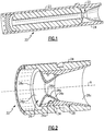
Figure 1 illustrates an example rocket motor that has a fragmenting nozzle system. -
Figure 2 illustrates a cross-section through a portion of the rocket motor and fragmenting nozzle system ofFigure 1 , not falling within the scope of the claimed invention. -
Figure 3 illustrates another example of a rocket motor and fragmenting nozzle system according to the present invention. -
Figure 4 illustrates a fragmenting nozzle system with an energetic material, according to the present invention. -
Figure 1 schematically illustrates a longitudinal cross-section through anexample rocket motor 20 that has a fragmentable or fragmentingnozzle system 22. Although not limited, therocket motor 20 may be a rocket booster that includes a solid fuel gas generator, such as asolid propellant grain 23 contained within the ramjet combustor that produces exhaust gases through the fragmentingnozzle system 22 to provide thrust. The examples herein are not limited to rocket motors and may be implemented in other types of vehicles. As will be described, the fragmentingnozzle system 22 enables dual mode operation using different nozzle throat geometries, as well as the ability to rapidly change from one mode to the other. For example, the modes of operation are different pressure modes for flow through the fragmentingnozzle system 22. -
Figure 2 illustrates an isolated view of a cross-section through a portion of therocket motor 20 and the fragmentingnozzle system 22. In this example, the fragmentingnozzle system 22 is within acase 24 of therocket motor 20. The fragmentingnozzle system 22 includes a first (or inner)nozzle 26 and a second (or outer)nozzle 28. Each of thenozzles 26/28 are convergent-divergent nozzles (with regard to left-to-right flow inFigure 2 ). Thefirst nozzle 26 is located at least partially within thesecond nozzle 28. In this regard, thefirst nozzle 26 lines the interior of thesecond nozzle 28, although the axial lengths of thenozzles 26/28 may differ. Thefirst nozzle 26, thesecond nozzle 28, or both may be fabricated from two or more arc segments. - The
nozzles 26/28 include, respectively,convergent sections 26a/28a that narrow torespective throat sections 26b/28b that expand to respectivedivergent sections 26c/28c. As shown, thethroat sections 26b/28b have different geometries with regard to at least minimum diametric size. Thenozzles 26/28 may alternatively or additionally differ in other flow path geometries, such as the geometries of the throat angles with regard to the slope angles of theconvergent sections 26a/28a anddivergent sections 26c/28c to a plane that is perpendicular to the central axis A of thenozzles 26/28. - At least a portion of an ignitor or fragmentation system 34 is situated between the first and
second nozzles 26/28 in this example. The fragmentation system 34 is operable to fragment thefirst nozzle 26. For instance, the fragmentation system 34 includes anenergetic material 34a, such as but not limited to an ignition cord, that is situated between the first andsecond nozzles 26/28. As an example, the ignition cord can be a flexible tube filled with an explosive, such as pentaerythritol tetranitrate (PETN). One non-limiting example cord is ITLX®. Other portions of the fragmentation system 34, such as electronics, if used, may be located elsewhere. - The
first nozzle 26 is formed of a brittle, fragmentable or fragmenting material. Thesecond nozzle 28 may be formed of a fragment- or pressure-resistant material. A fragmentable or fragmenting material substantially breaks apart into many small pieces or disintegrates to powder upon activation of the fragmentation system 34 to produce a pressure wave. A fragment-resistant material does not break apart from the pressure wave. For example, thesecond nozzle 28 substantially maintains its geometric profile after the pressure wave. - Upon selective triggering of the fragmentation system 34, the
first nozzle 26 rapidly fragments and is shed or expelled from therocket motor 20. For instance, thefirst nozzle 26 breaks apart into very small pieces that are no larger than approximately 3.5 inches and some of which are powder-sized; and within a period of less than 5 milliseconds thefirst nozzle 26 fragments and completely or substantially completely expels from therocket motor 20. In further examples, thefirst nozzle 26 breaks apart into pieces that have a maximum dimension that is smaller than the minimum diametric size of thethroat section 26b, to ensure that the pieces can be rapidly expelled. - The shedding of the
first nozzle 26 rapidly exposes the different nozzle geometry of thesecond nozzle 28. Thus, the fragmentingnozzle system 22 can initially be used in a first operation mode, such as for a first operation pressure. Thefirst nozzle 26 can then be removed or shed using the fragmentation system 34 such that the fragmentingnozzle system 22 can then be used in a second operation mode, such as for a second operation pressure. Moreover, since the fragmenting and expelling of the first nozzle is rapid, an operator can near-instantaneously change from the first mode of operation to the second. - In further examples, the first mode is a rocket boost mode to accelerate the rocket or vehicle, and the second mode is a sustain mode to maintain thrust or speed. The boost mode may utilize the
solid propellant grain 23, while the sustain mode may utilize ramjet combustion. For instance, a pyrotechnic ignitor lights thesolid propellant grain 23. Thegrain 23 burns and sends hot gases through thefirst nozzle 26 to accelerate the rocket to cruise speed. As the grain burns out, the pressure of the hot gases flowing through thefirst nozzle 26 decreases. The decrease triggers the fragmentation system 34 and fragments thefirst nozzle 26 into small pieces, which are rapidly expelled from the back of the fragmentingnozzle system 22 to expose the geometry of thesecond nozzle 28 and transition into the sustain mode. In the sustain mode thesecond nozzle 28 serves as a combustion chamber where hot gases produced by a gas generator propellant mix with air from a port cover to generate hot combustion gases through thesecond nozzle 28. In this regard, thedivergent section 28c of thesecond nozzle 28 serves as a ramjet nozzle. -
Figure 3 illustrates a portion of anotherexample rocket motor 120 and fragmentingnozzle system 122. In this disclosure, like reference numerals designate like elements where appropriate and reference numerals with the addition of one-hundred or multiples thereof designate modified elements that are understood to incorporate the same functions, features, and benefits of the corresponding elements. Thefirst nozzle 126 is at least partially disposed in thesecond nozzle 128. Thefirst nozzle 126 includes aforward leg 140, arear leg 142, and anintermediate leg 144 between theforward leg 140 and therear leg 142. Theforward leg 140 generally has the shape of a frustum and forms theconvergent section 26a. Therear leg 142 also has the shape of a frustum and forms thedivergent section 26c. Theforward leg 140 and therear leg 142 thus at least partially define the flow passage through thefirst nozzle 126. - At least a portion of an ignitor or fragmentation system 134 is disposed between the first and
second nozzles 126/128. In this example, the fragmentation system 134 is in the volume between theforward leg 140 and theintermediate leg 144 but may alternatively or additionally be between theintermediate leg 144 and therear leg 142. - The
first nozzle 126 is mounted via theintermediate leg 144. For example, thefirst nozzle 126 is exclusively secured by theintermediate leg 144 to at least one of thecase 24 or thesecond nozzle 128. For instance, theintermediate leg 144 fits into a mechanical joint 146 to secure thefirst nozzle 126 in the proper position. The mechanical joint 146 can be on thesecond nozzle 128, on thecase 24, or on thesecond nozzle 128 and thecase 24. - The
intermediate leg 144 is the sole support for thefirst nozzle 126. In this regard, theintermediate leg 144 is also configured to bear and transmit reaction forces of thefirst nozzle 126. For instance, theintermediate leg 144 has a "domed" or convexconical geometry 148 that slopes rearwards. The geometry serves to place theintermediate leg 144 in compression when transmitting reaction forces during use. The reaction forces are transmitted through theintermediate leg 144 to thecase 24. - The
forward leg 140 and therear leg 142 are cantilevered from theintermediate leg 144 and thus do not seal or mount to thecase 24. For instance, theforward leg 140 has aforward lip 140a that is spaced from thecase 24 such that there is a forward gap G1 between theforward lip 140a and thecase 24. Similarly, therear leg 142 has arear lip 142a that is spaced from thecase 24 such that there is a rear gap G2 between therear lip 142a and thecase 24. Theintermediate leg 144 has anintermediate lip 144a that is axially closer to therear lip 142a than to theforward lip 140a because of the slope of theintermediate leg 144. Theintermediate lip 144a may be configured to fit with themechanical joint 146. - The gaps G1/G2 permit flow into, respectively, the volume between the forward and
intermediate legs 140/144 and the volume between the intermediate andrear legs 144/142. The flow into these volumes serves to balance pressure across the walls of thefirst nozzle 126. In turn, the pressure balance facilitates the reduction in stress on the forward andrear legs 140/142. The reduction in stress enables thefirst nozzle 126 to be mounted solely by theintermediate leg 144, and also permits thefirst nozzle 126 to be formed of relatively brittle material that can be readily fragmented by the fragmentation system 134. In this example, the gap G1 is larger than the gap G2. The difference in size corresponds to the difference in pressure in the regions near the gaps G1/G2. For instance, there is higher pressure near theforward lip 140a than at therear lip 142a. The gap G1 is larger and thus less constrictive for the higher pressure flow. - As examples, the
first nozzle 126 is formed of a brittle material selected from ceramic material and graphite. For instance, thefirst nozzle 126 is formed predominantly or only of ceramic or graphite. A ceramic is an inorganic, nonmetallic solid material that includes metal, nonmetal, or semi-metal atoms primarily in ionic and covalent bonds. Example ceramics for thefirst nozzle 126 are oxide ceramics, such as but not limited to zirconium oxide (ZrO2). -
Figure 4 illustrates a modified example of therocket motor 120 and fragmentingnozzle system 122. In this example, thefragmentation system 234 includes an energetic material 234a disposed between the first andsecond nozzles 126/128, and the energetic material 234a abuts at least theintermediate leg 144. For example, the energetic material 234a is the ignition cord described above. In this example, the energetic material 234a is disposed between the forward andintermediate legs 140/144 and also abuts a portion of theforward leg 140. Additionally or alternatively, the energetic material can be arranged between the intermediate andrear legs 144/142. The close proximity of the energetic material 234a to theintermediate leg 144 ensures that thefragmentation system 234, once triggered, fragments theintermediate leg 144. Therefore, thefirst nozzle 126 is freed from attachment for discharge from therocket motor 120 to expose thesecond nozzle 128. At least theintermediate leg 144 fragments, but the remainder of thefirst nozzle 126 or portions thereof may also fragment. - Although a combination of features is shown in the illustrated examples, not all of them need to be combined to realize the benefits of various embodiments of this disclosure. In other words, a system designed according to an embodiment of this disclosure will not necessarily include all of the features shown in any one of the Figures or all of the portions schematically shown in the Figures. Moreover, selected features of one example embodiment may be combined with selected features of other example embodiments.
- The preceding description is exemplary rather than limiting in nature. Variations and modifications to the disclosed examples may become apparent to those skilled in the art that do not necessarily depart from this disclosure. The scope of legal protection given to this disclosure can only be determined by studying the following claims.
Claims (7)
- A rocket motor (120) comprising:a case (24);a nozzle system (122) including first and second nozzles (126,128) disposed in the case (24), the first nozzle (126) at least partially disposed in the second nozzle (128); anda fragmentation system (134; 234), at least a portion of which is disposed between the first (126) and second nozzles (128); wherein the first nozzle (126) includes:a convergent section (26a) that narrows to a throat section (26b) that expands to a divergent section (26c),a forward leg (140) forming the convergent section (26a), a rear leg (142) forming the divergent section (26c), and an intermediate leg (144) between the forward leg (140) and the rear leg (142),wherein the rear leg (142) has a rear lip (142a) that is spaced from the case (24) such that there is a rear gap (G2) between the rear lip (142a) and the case (24),the forward leg (140) and the rear leg (142) at least partially defining a flow passage through the first nozzle (126); characterised in that:the intermediate leg (144) has a convex conical geometry (148);the forward leg (140) has a forward lip (140a) that is spaced from the case (24) such that there is a forward gap (G1) between the forward lip (140a) and the case (24), andthe first nozzle (126) is exclusively secured by the intermediate leg (144) to at least one of the case (24) or the second nozzle (128).
- The rocket motor (120) as recited in claim 1, wherein the forward gap (G1) is radially larger than the rear gap (G2).
- The rocket motor (120) as recited in claim 1 or 2, wherein the intermediate leg (144) has an intermediate lip (144a) that is axially closer to the rear lip (142a) than to the forward lip (140a).
- The rocket motor (120) as recited in claim 1, 2 or 3, wherein the first nozzle (26; 126) is formed of a material selected from the group consisting of ceramic materials, graphite materials, and combinations thereof.
- The rocket motor (120) as recited in any preceding claim, wherein the fragmentation system (134; 234) includes an energetic material (234a) disposed between the first (126) and second nozzles (128).
- The rocket motor (120) as recited in claim 5, wherein the energetic material (234a) abuts the intermediate leg (144).
- The rocket motor (120) as recited in claim 5 or 6, wherein the energetic material (234a) is disposed between the forward leg (140) and the intermediate leg (144).
Priority Applications (1)
| Application Number | Priority Date | Filing Date | Title |
|---|---|---|---|
| PL16790812T PL3371446T3 (en) | 2015-11-06 | 2016-10-19 | Fragmenting nozzle system |
Applications Claiming Priority (2)
| Application Number | Priority Date | Filing Date | Title |
|---|---|---|---|
| US201562252269P | 2015-11-06 | 2015-11-06 | |
| PCT/US2016/057603 WO2017078931A1 (en) | 2015-11-06 | 2016-10-19 | Fragmenting nozzle system |
Publications (2)
| Publication Number | Publication Date |
|---|---|
| EP3371446A1 EP3371446A1 (en) | 2018-09-12 |
| EP3371446B1 true EP3371446B1 (en) | 2019-08-07 |
Family
ID=57227122
Family Applications (1)
| Application Number | Title | Priority Date | Filing Date |
|---|---|---|---|
| EP16790812.8A Active EP3371446B1 (en) | 2015-11-06 | 2016-10-19 | Fragmenting nozzle system |
Country Status (4)
| Country | Link |
|---|---|
| US (1) | US10690091B2 (en) |
| EP (1) | EP3371446B1 (en) |
| PL (1) | PL3371446T3 (en) |
| WO (1) | WO2017078931A1 (en) |
Cited By (1)
| Publication number | Priority date | Publication date | Assignee | Title |
|---|---|---|---|---|
| EP4180407A1 (en) | 2021-11-15 | 2023-05-17 | Deutsches Zentrum für Luft- und Raumfahrt e.V. | Fiber ceramic nozzle, use of a fiber ceramic nozzle, method for producing a fiber ceramic nozzle, and pusher chamber |
Families Citing this family (1)
| Publication number | Priority date | Publication date | Assignee | Title |
|---|---|---|---|---|
| CN109139296B (en) * | 2018-09-11 | 2020-01-24 | 中国人民解放军国防科技大学 | Rocket-based combined cycle engine |
Family Cites Families (8)
| Publication number | Priority date | Publication date | Assignee | Title |
|---|---|---|---|---|
| US3040517A (en) * | 1960-06-27 | 1962-06-26 | Carl V Ryden | Releasable rocket nozzle |
| US3372548A (en) * | 1965-06-17 | 1968-03-12 | Thiokol Chemical Corp | Rocket nozzle |
| US3648461A (en) * | 1970-05-13 | 1972-03-14 | Nasa | Solid propellent rocket motor nozzle |
| US3946557A (en) * | 1974-07-19 | 1976-03-30 | Thiokol Corporation | Rocket motor construction |
| US4022129A (en) * | 1976-01-16 | 1977-05-10 | The United States Of America As Represented By The Secretary Of The Air Force | Nozzle ejection system |
| GB2106988B (en) * | 1981-09-30 | 1984-10-03 | Baj Vickers Ltd | Rocket motors |
| US5779151A (en) | 1996-05-28 | 1998-07-14 | Regents Of The University Of California | Stepped nozzle |
| US6651438B2 (en) * | 2000-08-30 | 2003-11-25 | Alliant Techsystems Inc. | Rocket nozzle assembly having rotatable variable thrust control cylinders, and rocket assembly comprising the same |
-
2016
- 2016-10-19 EP EP16790812.8A patent/EP3371446B1/en active Active
- 2016-10-19 US US15/762,735 patent/US10690091B2/en active Active
- 2016-10-19 PL PL16790812T patent/PL3371446T3/en unknown
- 2016-10-19 WO PCT/US2016/057603 patent/WO2017078931A1/en not_active Ceased
Non-Patent Citations (1)
| Title |
|---|
| None * |
Cited By (2)
| Publication number | Priority date | Publication date | Assignee | Title |
|---|---|---|---|---|
| EP4180407A1 (en) | 2021-11-15 | 2023-05-17 | Deutsches Zentrum für Luft- und Raumfahrt e.V. | Fiber ceramic nozzle, use of a fiber ceramic nozzle, method for producing a fiber ceramic nozzle, and pusher chamber |
| DE102021129747A1 (en) | 2021-11-15 | 2023-05-17 | Arceon B.V. | Fiber ceramic nozzle, use of a fiber ceramic nozzle and method of manufacturing a fiber ceramic nozzle |
Also Published As
| Publication number | Publication date |
|---|---|
| EP3371446A1 (en) | 2018-09-12 |
| US10690091B2 (en) | 2020-06-23 |
| PL3371446T3 (en) | 2019-12-31 |
| WO2017078931A1 (en) | 2017-05-11 |
| US20180298847A1 (en) | 2018-10-18 |
Similar Documents
| Publication | Publication Date | Title |
|---|---|---|
| JP5216804B2 (en) | Portable guided bullet injection and separation device | |
| CN101529195B (en) | Gas generator with primary and secondary chambers | |
| US4213393A (en) | Gun projectile arranged with a base drag reducing system | |
| US5491973A (en) | Self-actuating control for rocket motor nozzle | |
| EP0298586B1 (en) | Multistage solid propellant rocket | |
| US3392673A (en) | Consumable pyrogen igniter | |
| JP6454285B2 (en) | Nozzle with a variable neck for a spacecraft thruster provided with a movable needle | |
| US3855789A (en) | Explosive coupling assembly | |
| US10690091B2 (en) | Fragmenting nozzle system | |
| US5671599A (en) | Solid-propellant rocket engine with inner and outer burner surfaces | |
| US4154141A (en) | Ultrafast, linearly-deflagration ignition system | |
| EP4295027B1 (en) | Ring-shaped booster rocket | |
| US6481198B1 (en) | Multi-stage rocket motor assembly including jettisonable launch motor integrated with flight igniter | |
| KR20210019189A (en) | Projectile containing ramjet engine | |
| US10598129B2 (en) | Fragmenting nozzle system | |
| US11067036B2 (en) | Combustor and jet engine having the same | |
| JP4619813B2 (en) | Two-stage thrust rocket motor | |
| US8408139B2 (en) | Projectile | |
| US9169806B2 (en) | Propulsion system for flying machine, particularly for a missile | |
| RU2312999C1 (en) | Solid-propellant rocket engine | |
| US3430445A (en) | Combined rocket-ramjet aircraft | |
| EP4251871B1 (en) | Multi-pulse solid propellant rocket motor and ignition method | |
| JP4619814B2 (en) | Two-stage thrust rocket motor | |
| EP4232700B1 (en) | Integrated propulsion and warhead system for an artillery round | |
| EP4211344B1 (en) | Variable burn-rate solid rocket motor ignition method |
Legal Events
| Date | Code | Title | Description |
|---|---|---|---|
| STAA | Information on the status of an ep patent application or granted ep patent |
Free format text: STATUS: UNKNOWN |
|
| STAA | Information on the status of an ep patent application or granted ep patent |
Free format text: STATUS: THE INTERNATIONAL PUBLICATION HAS BEEN MADE |
|
| PUAI | Public reference made under article 153(3) epc to a published international application that has entered the european phase |
Free format text: ORIGINAL CODE: 0009012 |
|
| STAA | Information on the status of an ep patent application or granted ep patent |
Free format text: STATUS: REQUEST FOR EXAMINATION WAS MADE |
|
| 17P | Request for examination filed |
Effective date: 20180503 |
|
| AK | Designated contracting states |
Kind code of ref document: A1 Designated state(s): AL AT BE BG CH CY CZ DE DK EE ES FI FR GB GR HR HU IE IS IT LI LT LU LV MC MK MT NL NO PL PT RO RS SE SI SK SM TR |
|
| AX | Request for extension of the european patent |
Extension state: BA ME |
|
| DAV | Request for validation of the european patent (deleted) | ||
| DAX | Request for extension of the european patent (deleted) | ||
| GRAP | Despatch of communication of intention to grant a patent |
Free format text: ORIGINAL CODE: EPIDOSNIGR1 |
|
| STAA | Information on the status of an ep patent application or granted ep patent |
Free format text: STATUS: GRANT OF PATENT IS INTENDED |
|
| INTG | Intention to grant announced |
Effective date: 20190219 |
|
| GRAS | Grant fee paid |
Free format text: ORIGINAL CODE: EPIDOSNIGR3 |
|
| GRAA | (expected) grant |
Free format text: ORIGINAL CODE: 0009210 |
|
| STAA | Information on the status of an ep patent application or granted ep patent |
Free format text: STATUS: THE PATENT HAS BEEN GRANTED |
|
| AK | Designated contracting states |
Kind code of ref document: B1 Designated state(s): AL AT BE BG CH CY CZ DE DK EE ES FI FR GB GR HR HU IE IS IT LI LT LU LV MC MK MT NL NO PL PT RO RS SE SI SK SM TR |
|
| REG | Reference to a national code |
Ref country code: GB Ref legal event code: FG4D |
|
| REG | Reference to a national code |
Ref country code: CH Ref legal event code: EP Ref country code: AT Ref legal event code: REF Ref document number: 1164262 Country of ref document: AT Kind code of ref document: T Effective date: 20190815 |
|
| REG | Reference to a national code |
Ref country code: DE Ref legal event code: R096 Ref document number: 602016018323 Country of ref document: DE |
|
| REG | Reference to a national code |
Ref country code: IE Ref legal event code: FG4D |
|
| REG | Reference to a national code |
Ref country code: NL Ref legal event code: MP Effective date: 20190807 |
|
| REG | Reference to a national code |
Ref country code: LT Ref legal event code: MG4D |
|
| PG25 | Lapsed in a contracting state [announced via postgrant information from national office to epo] |
Ref country code: BG Free format text: LAPSE BECAUSE OF FAILURE TO SUBMIT A TRANSLATION OF THE DESCRIPTION OR TO PAY THE FEE WITHIN THE PRESCRIBED TIME-LIMIT Effective date: 20191107 Ref country code: SE Free format text: LAPSE BECAUSE OF FAILURE TO SUBMIT A TRANSLATION OF THE DESCRIPTION OR TO PAY THE FEE WITHIN THE PRESCRIBED TIME-LIMIT Effective date: 20190807 Ref country code: NO Free format text: LAPSE BECAUSE OF FAILURE TO SUBMIT A TRANSLATION OF THE DESCRIPTION OR TO PAY THE FEE WITHIN THE PRESCRIBED TIME-LIMIT Effective date: 20191107 Ref country code: HR Free format text: LAPSE BECAUSE OF FAILURE TO SUBMIT A TRANSLATION OF THE DESCRIPTION OR TO PAY THE FEE WITHIN THE PRESCRIBED TIME-LIMIT Effective date: 20190807 Ref country code: PT Free format text: LAPSE BECAUSE OF FAILURE TO SUBMIT A TRANSLATION OF THE DESCRIPTION OR TO PAY THE FEE WITHIN THE PRESCRIBED TIME-LIMIT Effective date: 20191209 Ref country code: FI Free format text: LAPSE BECAUSE OF FAILURE TO SUBMIT A TRANSLATION OF THE DESCRIPTION OR TO PAY THE FEE WITHIN THE PRESCRIBED TIME-LIMIT Effective date: 20190807 Ref country code: LT Free format text: LAPSE BECAUSE OF FAILURE TO SUBMIT A TRANSLATION OF THE DESCRIPTION OR TO PAY THE FEE WITHIN THE PRESCRIBED TIME-LIMIT Effective date: 20190807 Ref country code: NL Free format text: LAPSE BECAUSE OF FAILURE TO SUBMIT A TRANSLATION OF THE DESCRIPTION OR TO PAY THE FEE WITHIN THE PRESCRIBED TIME-LIMIT Effective date: 20190807 |
|
| REG | Reference to a national code |
Ref country code: AT Ref legal event code: MK05 Ref document number: 1164262 Country of ref document: AT Kind code of ref document: T Effective date: 20190807 |
|
| PG25 | Lapsed in a contracting state [announced via postgrant information from national office to epo] |
Ref country code: GR Free format text: LAPSE BECAUSE OF FAILURE TO SUBMIT A TRANSLATION OF THE DESCRIPTION OR TO PAY THE FEE WITHIN THE PRESCRIBED TIME-LIMIT Effective date: 20191108 Ref country code: LV Free format text: LAPSE BECAUSE OF FAILURE TO SUBMIT A TRANSLATION OF THE DESCRIPTION OR TO PAY THE FEE WITHIN THE PRESCRIBED TIME-LIMIT Effective date: 20190807 Ref country code: AL Free format text: LAPSE BECAUSE OF FAILURE TO SUBMIT A TRANSLATION OF THE DESCRIPTION OR TO PAY THE FEE WITHIN THE PRESCRIBED TIME-LIMIT Effective date: 20190807 Ref country code: RS Free format text: LAPSE BECAUSE OF FAILURE TO SUBMIT A TRANSLATION OF THE DESCRIPTION OR TO PAY THE FEE WITHIN THE PRESCRIBED TIME-LIMIT Effective date: 20190807 Ref country code: ES Free format text: LAPSE BECAUSE OF FAILURE TO SUBMIT A TRANSLATION OF THE DESCRIPTION OR TO PAY THE FEE WITHIN THE PRESCRIBED TIME-LIMIT Effective date: 20190807 Ref country code: IS Free format text: LAPSE BECAUSE OF FAILURE TO SUBMIT A TRANSLATION OF THE DESCRIPTION OR TO PAY THE FEE WITHIN THE PRESCRIBED TIME-LIMIT Effective date: 20191207 |
|
| PG25 | Lapsed in a contracting state [announced via postgrant information from national office to epo] |
Ref country code: TR Free format text: LAPSE BECAUSE OF FAILURE TO SUBMIT A TRANSLATION OF THE DESCRIPTION OR TO PAY THE FEE WITHIN THE PRESCRIBED TIME-LIMIT Effective date: 20190807 |
|
| PG25 | Lapsed in a contracting state [announced via postgrant information from national office to epo] |
Ref country code: RO Free format text: LAPSE BECAUSE OF FAILURE TO SUBMIT A TRANSLATION OF THE DESCRIPTION OR TO PAY THE FEE WITHIN THE PRESCRIBED TIME-LIMIT Effective date: 20190807 Ref country code: DK Free format text: LAPSE BECAUSE OF FAILURE TO SUBMIT A TRANSLATION OF THE DESCRIPTION OR TO PAY THE FEE WITHIN THE PRESCRIBED TIME-LIMIT Effective date: 20190807 Ref country code: AT Free format text: LAPSE BECAUSE OF FAILURE TO SUBMIT A TRANSLATION OF THE DESCRIPTION OR TO PAY THE FEE WITHIN THE PRESCRIBED TIME-LIMIT Effective date: 20190807 Ref country code: EE Free format text: LAPSE BECAUSE OF FAILURE TO SUBMIT A TRANSLATION OF THE DESCRIPTION OR TO PAY THE FEE WITHIN THE PRESCRIBED TIME-LIMIT Effective date: 20190807 Ref country code: IT Free format text: LAPSE BECAUSE OF FAILURE TO SUBMIT A TRANSLATION OF THE DESCRIPTION OR TO PAY THE FEE WITHIN THE PRESCRIBED TIME-LIMIT Effective date: 20190807 |
|
| PG25 | Lapsed in a contracting state [announced via postgrant information from national office to epo] |
Ref country code: IS Free format text: LAPSE BECAUSE OF FAILURE TO SUBMIT A TRANSLATION OF THE DESCRIPTION OR TO PAY THE FEE WITHIN THE PRESCRIBED TIME-LIMIT Effective date: 20200224 Ref country code: SM Free format text: LAPSE BECAUSE OF FAILURE TO SUBMIT A TRANSLATION OF THE DESCRIPTION OR TO PAY THE FEE WITHIN THE PRESCRIBED TIME-LIMIT Effective date: 20190807 Ref country code: SK Free format text: LAPSE BECAUSE OF FAILURE TO SUBMIT A TRANSLATION OF THE DESCRIPTION OR TO PAY THE FEE WITHIN THE PRESCRIBED TIME-LIMIT Effective date: 20190807 Ref country code: CZ Free format text: LAPSE BECAUSE OF FAILURE TO SUBMIT A TRANSLATION OF THE DESCRIPTION OR TO PAY THE FEE WITHIN THE PRESCRIBED TIME-LIMIT Effective date: 20190807 Ref country code: MC Free format text: LAPSE BECAUSE OF FAILURE TO SUBMIT A TRANSLATION OF THE DESCRIPTION OR TO PAY THE FEE WITHIN THE PRESCRIBED TIME-LIMIT Effective date: 20190807 |
|
| REG | Reference to a national code |
Ref country code: CH Ref legal event code: PL |
|
| REG | Reference to a national code |
Ref country code: DE Ref legal event code: R097 Ref document number: 602016018323 Country of ref document: DE |
|
| PLBE | No opposition filed within time limit |
Free format text: ORIGINAL CODE: 0009261 |
|
| STAA | Information on the status of an ep patent application or granted ep patent |
Free format text: STATUS: NO OPPOSITION FILED WITHIN TIME LIMIT |
|
| PG2D | Information on lapse in contracting state deleted |
Ref country code: IS |
|
| PG25 | Lapsed in a contracting state [announced via postgrant information from national office to epo] |
Ref country code: CH Free format text: LAPSE BECAUSE OF NON-PAYMENT OF DUE FEES Effective date: 20191031 Ref country code: LU Free format text: LAPSE BECAUSE OF NON-PAYMENT OF DUE FEES Effective date: 20191019 Ref country code: LI Free format text: LAPSE BECAUSE OF NON-PAYMENT OF DUE FEES Effective date: 20191031 |
|
| 26N | No opposition filed |
Effective date: 20200603 |
|
| REG | Reference to a national code |
Ref country code: BE Ref legal event code: MM Effective date: 20191031 |
|
| PG25 | Lapsed in a contracting state [announced via postgrant information from national office to epo] |
Ref country code: BE Free format text: LAPSE BECAUSE OF NON-PAYMENT OF DUE FEES Effective date: 20191031 Ref country code: SI Free format text: LAPSE BECAUSE OF FAILURE TO SUBMIT A TRANSLATION OF THE DESCRIPTION OR TO PAY THE FEE WITHIN THE PRESCRIBED TIME-LIMIT Effective date: 20190807 |
|
| PG25 | Lapsed in a contracting state [announced via postgrant information from national office to epo] |
Ref country code: IE Free format text: LAPSE BECAUSE OF NON-PAYMENT OF DUE FEES Effective date: 20191019 |
|
| PG25 | Lapsed in a contracting state [announced via postgrant information from national office to epo] |
Ref country code: CY Free format text: LAPSE BECAUSE OF FAILURE TO SUBMIT A TRANSLATION OF THE DESCRIPTION OR TO PAY THE FEE WITHIN THE PRESCRIBED TIME-LIMIT Effective date: 20190807 |
|
| PG25 | Lapsed in a contracting state [announced via postgrant information from national office to epo] |
Ref country code: MT Free format text: LAPSE BECAUSE OF FAILURE TO SUBMIT A TRANSLATION OF THE DESCRIPTION OR TO PAY THE FEE WITHIN THE PRESCRIBED TIME-LIMIT Effective date: 20190807 Ref country code: HU Free format text: LAPSE BECAUSE OF FAILURE TO SUBMIT A TRANSLATION OF THE DESCRIPTION OR TO PAY THE FEE WITHIN THE PRESCRIBED TIME-LIMIT; INVALID AB INITIO Effective date: 20161019 |
|
| PG25 | Lapsed in a contracting state [announced via postgrant information from national office to epo] |
Ref country code: MK Free format text: LAPSE BECAUSE OF FAILURE TO SUBMIT A TRANSLATION OF THE DESCRIPTION OR TO PAY THE FEE WITHIN THE PRESCRIBED TIME-LIMIT Effective date: 20190807 |
|
| P01 | Opt-out of the competence of the unified patent court (upc) registered |
Free format text: CASE NUMBER: APP_47166/2024 Effective date: 20240814 |
|
| PGFP | Annual fee paid to national office [announced via postgrant information from national office to epo] |
Ref country code: DE Payment date: 20251029 Year of fee payment: 10 |
|
| PGFP | Annual fee paid to national office [announced via postgrant information from national office to epo] |
Ref country code: GB Payment date: 20251027 Year of fee payment: 10 |
|
| PGFP | Annual fee paid to national office [announced via postgrant information from national office to epo] |
Ref country code: FR Payment date: 20251027 Year of fee payment: 10 |
|
| PGFP | Annual fee paid to national office [announced via postgrant information from national office to epo] |
Ref country code: PL Payment date: 20251001 Year of fee payment: 10 |