EP3371355B1 - Crimping machine for the treatment of synthetic fibres - Google Patents
Crimping machine for the treatment of synthetic fibres Download PDFInfo
- Publication number
- EP3371355B1 EP3371355B1 EP16801575.8A EP16801575A EP3371355B1 EP 3371355 B1 EP3371355 B1 EP 3371355B1 EP 16801575 A EP16801575 A EP 16801575A EP 3371355 B1 EP3371355 B1 EP 3371355B1
- Authority
- EP
- European Patent Office
- Prior art keywords
- belt
- crimping machine
- machine according
- drive member
- drum
- Prior art date
- Legal status (The legal status is an assumption and is not a legal conclusion. Google has not performed a legal analysis and makes no representation as to the accuracy of the status listed.)
- Active
Links
Images

Classifications
-
- D—TEXTILES; PAPER
- D02—YARNS; MECHANICAL FINISHING OF YARNS OR ROPES; WARPING OR BEAMING
- D02G—CRIMPING OR CURLING FIBRES, FILAMENTS, THREADS, OR YARNS; YARNS OR THREADS
- D02G1/00—Producing crimped or curled fibres, filaments, yarns, or threads, giving them latent characteristics
- D02G1/12—Producing crimped or curled fibres, filaments, yarns, or threads, giving them latent characteristics using stuffer boxes
Definitions
- the present invention relates to a crimping machine, namely an apparatus for processing chemical fibers intended to confer to these fibers, being smooth outbound the forming units, a continuous corrugated configuration, called "crimp", which is essential to allow the subsequent spinning.
- the present invention finds particular application in the processing of chemical fibers (e.g. textiles), both synthetic and man-made, such as cellulosic, polyolefin, aramid, polyamide, polyester, polyvinyl, polyacrylic fibers, etc.
- chemical fibers e.g. textiles
- synthetic and man-made such as cellulosic, polyolefin, aramid, polyamide, polyester, polyvinyl, polyacrylic fibers, etc.
- polyester fibers without however losing generality, because the object of the present invention can also be applied and used in the treatment and processing of other kinds of chemical fibers, including but not limited to those listed above.
- the crimping machines are devices placed along the spinning lines of the chemical fibers, in particular operatively placed downstream of the spinning stations (in cui the spinning rovings are produced at very high speed), in the second processing stage of fibers.
- the fibers are generally treated both mechanically and chemically (oiling and ironing) before being sent in the form of a continuous "cable" of material to the crimping machine.
- This solution provides the abutment of a pair of counterrotating drums, both motorized, to define a drive section of the fibers.
- Such fibers are driven inside a crimping room, so defined because it constitutes the housing in which the fibers are subjected to the mechanical stress that leads them to a collapse by peak load.
- the two drums drive the fibers inside the crimping chamber at a predetermined speed, such that the pressure generated at the contact with the boundaries of the room, or with the previously crimped fibers, involves a permanent "curling" of the fibers.
- this type of crimping introduces several problems related both to reliability and productivity when the working speeds exceed certain values (from 500 to 1200 m/min according to the design of the apparatus).
- One prior art crimping machine of this type is known from document US 3 766 726 .
- the "movable" drum tends to oscillate and hop on the fixed one determining a hammering effect highly wearing and sometimes dangerous.
- the high inertia of the rollers (due to the need to generate a sufficient friction to drive the fiber which involves a heavy dimensioning) imposes significant constraints to the advancement speed, or peripheral speed, of the same, which is hardly more than 400 m/min.
- Such a speed is typical of a "2-step spinning process” like that of the spun polyester, where the crimping must be conducted at this limit speed (second step) corresponding to not more than a fraction of the optimum advancement speed of the fiber in the previous spinning step (first step, typically variable between 1200 and 2000 m/min and above).
- the crimping machine is the "bottleneck" of the production process.
- the metal belts are maintained substantially adherent, in order to generate a sufficient friction, by means of pressurization action by suitable blowing means.
- the object of the present invention is to provide a crimping machine allowing to overcome the above-mentioned drawbacks of the known art.
- Another object of the present invention is to provide a crimping machine which is compact and easy to manufacture.
- a crimping machine having the features of one or more of the following claims from 1 to 17 and in particular by a crimping machine comprising a conduit extending along an advancement direction between an inlet opening, associable to means for feeding a bundle of fibre material, and an outlet opening, a drive unit arranged along said conduit in order to split it into a first and a second portion, comprising a first and a second drive member abutted to each other in correspondence of at least a maximum proximity area, in cui they exert a driving action on said bundle of fibre material, and a crimping chamber arranged immediately downstream of the drive unit, and configured to receive said bundle of fibre material contributing to the mechanical deformation of the same by peak load.
- the crimping chamber is preferably abutted to and facing a discharge outlet of the drive unit.
- the crimping machine according to the present invention is a compact machine, wherein all the components are identifiable between them in a single device.
- the first and the second drive member are shaped so as to define a deviation along said conduit such that said first portion of the conduit has a different orientation with respect to said second portion.
- the first member at least in correspondence of said maximum proximity area, is flexible in order to move towards or away from the second member according to the thickness of said bundle.
- the presence of a deviation in the conduit allows to increase the frictional force on the fiber, pushed by its own inertia against the deviation (i.e. against the conduit walls), with no need to increase the contact pressure between the two drive members, thus allowing to obtain maximum performance in terms of production speed.
- the first drive member comprises at least one belt in part lying on said second member so that the second member contacts the belt at the maximum proximity area and keeps it in tension.
- the first drive member comprises at least one pair of rollers and a belt wound around said rollers movable along said advancement direction, in cui the belt, at least at said maximum proximity area, has a concave conformation defining at least in part the above-mentioned deviation of the conduit.
- the second drive member comprises at least one drum around which, in correspondence of said maximum proximity area, the belt of the first member is partially wrapped.
- the maximum proximity area is defined between the belt of the first member and the drum of the second member, ensuring on one hand the maximum reduction of inertia (the drum has no other movement than rotation on its own axis, the belt instead follows the variation of the bundle thickness but has very low inertia) and on the other the maximum drive effect (concave portion and drum).
- the first member of the drive unit includes blowing means placed inside the belt (i.e. inside the ring path defined by the belt) and configured to keep it adherent to the drum and in tension during operation.
- the crimping machine is very compact and easy to transport and install.
- number 1 indicates a crimping machine according to the present invention.
- the expression crimping machine 1 defines a device for the treatment of fiber material, mainly synthetic fibers, configured to perform a continuous sequence of corrugations or pleats of linear filaments coming from previous processing stations.
- the treated fibers are typically chemical, such as cellulosic, polyolefin, aramid, polyamide, polyester, polyvinyl, polyacrylic fibers, etc.
- the crimping machine 1 is therefore to be used in a spinning system of such fibers, both intended for the textile industry and for another industry.
- the crimping machine 1 therefore includes a conduit 2 extending along an advancement direction "A" between an inlet opening 2a, associable to means for feeding (not shown) a bundle "F" of fibre material, and an outlet opening 2b.
- the drive unit 3 splits the conduit into a first (inlet) portion T1 and a second (output) portion T2.
- the drive unit 3 comprising a first drive member 4 and a second drive member 5, reciprocally abutting at least at a maximum proximity area "Z", in cui they exert a driving action on said bundle "F" of fibre material.
- the maximum proximity area "Z" is a contact area between the two drive members 4, 5, wherein the reduced or preferably absent passage section along with the movement of the members in the advance direction "A" generates a drive effect on the fibers.
- first 4 and the second member 5 are substantially in contact, with the possibility to move (elastically) away and towards each other based on the thickness of the bundle "F" of fiber material.
- the first member 4, at least in correspondence of the maximum proximity area "Z" is flexible in order to move towards or away from the second member 5 according to the thickness of said bundle "F".
- first 4 and the second drive member 5 are (rigidly) movable towards and away from each other between a withdrawn position, rest, and an approached position, operational.
- the first 4 and the second drive member 5 are shaped so as to define a deviation "D" along said conduit 2, such that the inlet opening of the conduit 2 (thus the first portion T1) has a different orientation with respect to the outlet opening (thus to the second portion T2).
- the conduit 2 has a first T1 and a second portion T2 having respectively a first and a second orientation, out of phase between them by an angle defined by said deviation "D".
- the first 4 and the second drive member 5 therefore delimit in part the conduit 2 and determine a curve or a deviation "D" of it in correspondence of which there is an increase of the frictional force, namely the drive effect, in the bundle "F" of material.
- the first drive member 4 comprises at least one belt 7 in part lying on said second member 5 so that said second member 5 contacts the belt 7 at the maximum proximity area "Z" and keeps it in tension.
- the first drive member 4 comprises at least a pair of rollers 6 and a belt 7 wrapped around them.
- the rollers 6 (at least one of them) are motorized to impart to the belt 7 a movement along the advance direction "A".
- the belt 7 has an operative portion 7a and a return portion 7b between the two rollers 6.
- the operative portion 7a is proximal to the second drive member 5, while return portion 7b is distal from it.
- the belt 7, at least in correspondence of said maximum proximity area "Z", has a concave shape defining at least partially the deviation "D" of the conduit 2.
- the operating portion 7a has a concave shape defining the deviation "D".
- the return portion 7b has a convex shape.
- the belt 7 is made of flexible material; preferably the belt is made of metal, more preferably of stainless steel, but also of synthetic composite material with textile core made of carbon fiber or glass fiber.
- the first portion 7a in the approached position the first portion 7a has a convex shape, while in the withdrawn position the first portion 7a has a substantially linear shape.
- this belt 7 has a thickness lower than 1 mm, preferably lower than 0.5 mm, more preferably of about 0.2 mm.
- the second drive member 5 comprises at least one drum 8 around which, in correspondence of said maximum proximity area "Z", the belt 7 of the first member 4 is partially wrapped.
- the conduit 2 is then at least partially delimited between the belt 7 and the drum 8; more precisely, the maximum proximity area "Z" is defined between said belt 7 and said drum 8.
- the drum 8 is therefore in part interposed between the rollers 6 of the first member 4 of entrainment; thereby the operating portion 7a of the belt 7 is wound on the drum 8.
- a line "L" connecting the rotation centres of the rollers 6 of the first drive member 4 is placed at a distance from a rotation centre of the drum 8, which is less than the sum of the diameters of said drum 8 and one of said rollers 6.
- distance refers to a measurement assessed orthogonally to the connecting line "L".
- the drum 8 defines the concavity of the operating portion 7a of the belt 7.
- the maximum proximity area "Z" extends curved between an inlet area Z in and an outlet area Z out , each defined between the periphery of the drum 8 and the periphery of a respective roller 6 of the first drive member 4.
- the inlet opening and the inlet area Z in are substantially coincident.
- the boundaries of the drum 8 is placed at a distance lower than 1 mm from the respective roller 6, more preferably lower than 0.5 mm, even more preferably of about 0.2 mm, increased by the expected thickness of the belt of fiber to be crimped, typically less than 0.5 mm
- drum 8 and the belt 7 works substantially at the same speed along the advance direction, as well as to the same speed of the bundle "F" of material coming from a plant for the production of the fiber.
- the speed of realization of the crimping is kept high, comparable to that of a production/spinning plant, considerably increasing the productivity of the line.
- the first drive member 4 comprises blowing means 9 placed inside said belt 7 and configured to keep it adherent to the drum 8 and in tension during the operation.
- the blowing means 9 are operatively active on the return portion 7a of the belt 7, in order to tension said portion away from the drum 8, generating the required tension to drive the fiber while ensuring the possibility to adapt the position of the operating portion 7a (thus the amplitude of the maximum proximity area "Z") to the thickness of the bundle "F".
- the blowing means 9 generate substantially a "balloon effect" in correspondence of the return portion of the belt 7.
- the tension of the belt 7 is determined by a synergistic effect of the blowing means 9 and of the position of the drum 8.
- the blowing means 9 are preferably defined by at least one distributing member 9a configured to dispense a pressurized fluid (for example air or water vapor) on an inner face of the strip 7 in order to advance it toward the second drive member 5.
- a pressurized fluid for example air or water vapor
- the belt 7 abuts on the bundle "F" of fibers as a flexible membrane under the effect of the fluid pressure, remaining adherent to the fiber.
- the drum 8 remains rigid and defines an abutment for the fibers, increasing the friction and therefore the drive effect.
- the first drive member 4 includes an abutment member 15 distal from the second member 5 with respect to the belt 7 and placed at a predetermined distance from said belt 7.
- the abutment member 15 is defined by a skid 15a made of anti-friction material.
- Anti-friction material in this text defines materials having very low friction coefficient and, preferably, a high resistance to wear and crushing.
- the dynamic friction coefficient of the skid 15a with the steel of the belt 7 is less than 0.2, more preferably less than 0.1.
- the abutment member 15 i.e. the skid 15a
- the skid 15a is made of graphite or the like.
- said abutment member has a concave surface contacting with the belt 7, preferably substantially matching the curvature of the operating portion 7a of the belt 7.
- the abutment member 15 is placed at a distance from the belt 7 (in the operating condition) from 0.5 and 2 mm (preferably equal to about 1 mm) exceeding the expected thickness of the bundle "F".
- the machine 1 Immediately downstream of the drive unit 3, the machine 1 includes a crimping chamber 10 configured to receive the bundle "F" of fibre material contributing to the mechanical deformation of the same by peak load.
- the crimping chamber 10 has an orientation corresponding to said second portion T2 of the conduit.
- the crimping chamber 10 is part of said second portion T2 defines an extension of it.
- the crimping is made partly inside the drive unit 3 before entering the crimping chamber 10, in which it will complete.
- the crimping preferably begins as a result of the combined action of the drum 8 and the belt 7 in the maximum proximity area "Z".
- the crimping chamber 10 is a chamber with a confined volume, in which, when used, is driven the bundle "F" of high-speed material by means of the drive unit 3.
- the crimping chamber 10 faces directly to the outlet area Z out of the drive unit; in other words, the output area of the drive unit substantially corresponds to an inlet portion of the crimping chamber 10.
- the sudden stop of the advancement due to the confinement in the chamber involves a mechanical deformation of the fibers, which assume a characteristic corrugated shape on the plane (two-dimensional crimping).
- the crimping chamber 10 thus includes an inlet portion 10a, placed in correspondence of the outlet area Z out of the drive unit 3, and an operating portion 10b shaped to determine said load peak deformation of the fibers.
- the inlet portion 10a is preferably shaped as a blade engaged in proximity of the drum 8 and of a roller 6 of the first member 4.
- the inlet portion 10a therefore defines a wedge which engages in the proximity of the outlet area Z out , fully limiting the gap between the drive unit 3 and the crimping chamber 10.
- At least one blowing nozzle 12 for guiding the bundle "F" of fiber material within the inlet portion 10a.
- the blown fluid depending on the treated fiber type, may be gaseous such as steam or air, but also liquid such as water.
- this nozzle 12 is associated with means for generation of steam 13 and is configured to dispense pressurized steam from the nozzle 12 itself in order to constrain the movement of the guiding fibers towards the crimping chamber 10.
- the means for steam generation are replaced with an air compressor configured to dispense, through a heater, hot air (up to 350°) or, with a dispensing circuit, pressurized heated water.
- the operating portion 10b of the crimping chamber 10 comprises at least two pairs 14 of walls longitudinal to each other, facing two by two to delimit it laterally.
- At least the walls of a pair 14 are movable towards and away from each other between an active position, in which they are proximal, and an inactive position, in which they are distal.
- these walls 14 are pivoted to a frame in the proximal area to the drive unit 3 and are configured to reciprocally rotate away and towards each other.
- the movement is preferably obtained by means of hydraulic/pneumatic actuators, but it may also include other types of activations.
- the invention achieves the intended objects and achieves important advantages.
- the presence of a deviation in the drive conduit allows to maintain a high friction with the fibers, i.e. the drive effect, even without the need to increase the operating pressure of the active members in the drive.
Landscapes
- Engineering & Computer Science (AREA)
- Mechanical Engineering (AREA)
- Textile Engineering (AREA)
- Yarns And Mechanical Finishing Of Yarns Or Ropes (AREA)
- Treatment Of Fiber Materials (AREA)
Description
- The present invention relates to a crimping machine, namely an apparatus for processing chemical fibers intended to confer to these fibers, being smooth outbound the forming units, a continuous corrugated configuration, called "crimp", which is essential to allow the subsequent spinning.
- The present invention finds particular application in the processing of chemical fibers (e.g. textiles), both synthetic and man-made, such as cellulosic, polyolefin, aramid, polyamide, polyester, polyvinyl, polyacrylic fibers, etc.
- Note that in the currently known technical description it will be made explicit reference to the polyester fibers, without however losing generality, because the object of the present invention can also be applied and used in the treatment and processing of other kinds of chemical fibers, including but not limited to those listed above.
- As above mentioned, the crimping machines are devices placed along the spinning lines of the chemical fibers, in particular operatively placed downstream of the spinning stations (in cui the spinning rovings are produced at very high speed), in the second processing stage of fibers.
- In this second stage, the fibers are generally treated both mechanically and chemically (oiling and ironing) before being sent in the form of a continuous "cable" of material to the crimping machine.
- Nowadays it is mainly known a single solution, with more or less variations, to obtain an efficient crimping.
- This solution provides the abutment of a pair of counterrotating drums, both motorized, to define a drive section of the fibers.
- Such fibers are driven inside a crimping room, so defined because it constitutes the housing in which the fibers are subjected to the mechanical stress that leads them to a collapse by peak load.
- In fact, the two drums drive the fibers inside the crimping chamber at a predetermined speed, such that the pressure generated at the contact with the boundaries of the room, or with the previously crimped fibers, involves a permanent "curling" of the fibers.
- Disadvantageously, this type of crimping introduces several problems related both to reliability and productivity when the working speeds exceed certain values (from 500 to 1200 m/min according to the design of the apparatus). One prior art crimping machine of this type is known from document
US 3 766 726 . - With regard to reliability, the presence of a pair of metal rollers abutted and movable away and towards each other to vary the passage section based on the thickness of the fiber entails a considerable wear on the boundaries of said rollers.
- In fact, at high-speed, given the low thickness of the fibers (tenths of a millimeter) and their high speed of advance, the "movable" drum tends to oscillate and hop on the fixed one determining a hammering effect highly wearing and sometimes dangerous.
- With regard to productivity, the high inertia of the rollers (due to the need to generate a sufficient friction to drive the fiber which involves a heavy dimensioning) imposes significant constraints to the advancement speed, or peripheral speed, of the same, which is hardly more than 400 m/min.
- Such a speed is typical of a "2-step spinning process" like that of the spun polyester, where the crimping must be conducted at this limit speed (second step) corresponding to not more than a fraction of the optimum advancement speed of the fiber in the previous spinning step (first step, typically variable between 1200 and 2000 m/min and above).
- In other words, in the known art the crimping machine is the "bottleneck" of the production process.
- To resolve this problem, several years ago the same Applicant realized a high-speed crimping machine, published in
patent document US 5564174 , which replaced the two drums with a pair of metal belts having respective operating portions placed opposed to each other. - In that solution, the metal belts are maintained substantially adherent, in order to generate a sufficient friction, by means of pressurization action by suitable blowing means.
- Despite this actually allows to fix the problems of inertia and wear of the traditional crimping machines, the poor grip of the belts on the fibers makes it difficult the application at industrial level, where the effect of push/drive on the fiber presented to the crimping chamber may be insufficient to ensure absolute reliability of the process.
- The object of the present invention is to provide a crimping machine allowing to overcome the above-mentioned drawbacks of the known art.
- In particular, it is an object of the present invention to provide a crimping machine with high performance both in terms of production speed and reliability.
- Yet, another object of the present invention is to provide a crimping machine which is compact and easy to manufacture.
- Said objects are achieved by a crimping machine having the features of one or more of the following claims from 1 to 17 and in particular by a crimping machine comprising a conduit extending along an advancement direction between an inlet opening, associable to means for feeding a bundle of fibre material, and an outlet opening, a drive unit arranged along said conduit in order to split it into a first and a second portion, comprising a first and a second drive member abutted to each other in correspondence of at least a maximum proximity area, in cui they exert a driving action on said bundle of fibre material, and a crimping chamber arranged immediately downstream of the drive unit, and configured to receive said bundle of fibre material contributing to the mechanical deformation of the same by peak load.
- Note that "immediately downstream" indicates that the crimping chamber is preferably abutted to and facing a discharge outlet of the drive unit.
- Therefore, the crimping machine according to the present invention is a compact machine, wherein all the components are identifiable between them in a single device.
- According to one aspect of the present invention, the first and the second drive member are shaped so as to define a deviation along said conduit such that said first portion of the conduit has a different orientation with respect to said second portion.
- Furthermore, preferably the first member, at least in correspondence of said maximum proximity area, is flexible in order to move towards or away from the second member according to the thickness of said bundle.
- Advantageously, the presence of a deviation in the conduit allows to increase the frictional force on the fiber, pushed by its own inertia against the deviation (i.e. against the conduit walls), with no need to increase the contact pressure between the two drive members, thus allowing to obtain maximum performance in terms of production speed.
- Preferably, the first drive member comprises at least one belt in part lying on said second member so that the second member contacts the belt at the maximum proximity area and keeps it in tension.
- More preferably, the first drive member comprises at least one pair of rollers and a belt wound around said rollers movable along said advancement direction, in cui the belt, at least at said maximum proximity area, has a concave conformation defining at least in part the above-mentioned deviation of the conduit.
- More preferably, the second drive member comprises at least one drum around which, in correspondence of said maximum proximity area, the belt of the first member is partially wrapped.
- Advantageously, therefore, the maximum proximity area (or contact area) is defined between the belt of the first member and the drum of the second member, ensuring on one hand the maximum reduction of inertia (the drum has no other movement than rotation on its own axis, the belt instead follows the variation of the bundle thickness but has very low inertia) and on the other the maximum drive effect (concave portion and drum).
- To maximize the yield of the machine, also, the first member of the drive unit includes blowing means placed inside the belt (i.e. inside the ring path defined by the belt) and configured to keep it adherent to the drum and in tension during operation.
- So, thanks to the coupling between the curved belt and the drum, interposed between the two rollers driving the belt, the crimping machine is very compact and easy to transport and install.
- These and other features and advantages will become more apparent from the following exemplary, therefore non-limiting, description of a preferred, therefore not exclusive, embodiment of a crimping machine according to what is shown in the appended drawing tables, in which:
-
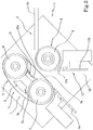
Figure 1 shows a schematic side view of a crimping machine according to the present invention, in an operative condition; -
Figure 2 shows a schematic side view of the crimping machine ofFigure 1 in a rest condition; -
Figure 3 shows a detail ofFigure 1 . - With reference to the appended figures,
number 1 indicates a crimping machine according to the present invention. - The
expression crimping machine 1 defines a device for the treatment of fiber material, mainly synthetic fibers, configured to perform a continuous sequence of corrugations or pleats of linear filaments coming from previous processing stations. - The treated fibers are typically chemical, such as cellulosic, polyolefin, aramid, polyamide, polyester, polyvinyl, polyacrylic fibers, etc.
- The
crimping machine 1 is therefore to be used in a spinning system of such fibers, both intended for the textile industry and for another industry. - The
crimping machine 1 therefore includes a conduit 2 extending along an advancement direction "A" between aninlet opening 2a, associable to means for feeding (not shown) a bundle "F" of fibre material, and an outlet opening 2b. - It is also provided a
drive unit 3 arranged along the conduit 2. - The
drive unit 3 splits the conduit into a first (inlet) portion T1 and a second (output) portion T2. - The
drive unit 3 comprising a first drive member 4 and asecond drive member 5, reciprocally abutting at least at a maximum proximity area "Z", in cui they exert a driving action on said bundle "F" of fibre material. - Preferably, the maximum proximity area "Z" is a contact area between the two
drive members 4, 5, wherein the reduced or preferably absent passage section along with the movement of the members in the advance direction "A" generates a drive effect on the fibers. - In the preferred embodiment, the first 4 and the
second member 5 are substantially in contact, with the possibility to move (elastically) away and towards each other based on the thickness of the bundle "F" of fiber material. - Therefore, the first member 4, at least in correspondence of the maximum proximity area "Z", is flexible in order to move towards or away from the
second member 5 according to the thickness of said bundle "F". - Furthermore, note that the first 4 and the
second drive member 5 are (rigidly) movable towards and away from each other between a withdrawn position, rest, and an approached position, operational. - All the considerations related to the distances and gaps that are created along the conduit 2 are made in this text with reference to the approached position of the two members, being the main purpose of the withdrawn position that of cleaning and maintenance, but not operational.
- The first 4 and the
second drive member 5 are shaped so as to define a deviation "D" along said conduit 2, such that the inlet opening of the conduit 2 (thus the first portion T1) has a different orientation with respect to the outlet opening (thus to the second portion T2). - Therefore, the conduit 2 has a first T1 and a second portion T2 having respectively a first and a second orientation, out of phase between them by an angle defined by said deviation "D".
- The first 4 and the
second drive member 5 therefore delimit in part the conduit 2 and determine a curve or a deviation "D" of it in correspondence of which there is an increase of the frictional force, namely the drive effect, in the bundle "F" of material. - Preferably, the first drive member 4 comprises at least one belt 7 in part lying on said
second member 5 so that saidsecond member 5 contacts the belt 7 at the maximum proximity area "Z" and keeps it in tension. - Preferably, the first drive member 4 comprises at least a pair of
rollers 6 and a belt 7 wrapped around them. - The rollers 6 (at least one of them) are motorized to impart to the
belt 7 a movement along the advance direction "A". - Therefore, the belt 7 has an
operative portion 7a and areturn portion 7b between the tworollers 6. - The
operative portion 7a is proximal to thesecond drive member 5, whilereturn portion 7b is distal from it. - The belt 7, at least in correspondence of said maximum proximity area "Z", has a concave shape defining at least partially the deviation "D" of the conduit 2.
- Therefore, the
operating portion 7a has a concave shape defining the deviation "D". - Preferably, however, the
return portion 7b has a convex shape. - In particular, in the belt 7 is made of flexible material; preferably the belt is made of metal, more preferably of stainless steel, but also of synthetic composite material with textile core made of carbon fiber or glass fiber.
- In the preferred embodiment, in the approached position the
first portion 7a has a convex shape, while in the withdrawn position thefirst portion 7a has a substantially linear shape. - Dimensionally, this belt 7 has a thickness lower than 1 mm, preferably lower than 0.5 mm, more preferably of about 0.2 mm.
- The
second drive member 5 comprises at least onedrum 8 around which, in correspondence of said maximum proximity area "Z", the belt 7 of the first member 4 is partially wrapped. - The conduit 2 is then at least partially delimited between the belt 7 and the
drum 8; more precisely, the maximum proximity area "Z" is defined between said belt 7 and saiddrum 8. - The
drum 8 is therefore in part interposed between therollers 6 of the first member 4 of entrainment; thereby the operatingportion 7a of the belt 7 is wound on thedrum 8. - In other words, a line "L" connecting the rotation centres of the
rollers 6 of the first drive member 4 is placed at a distance from a rotation centre of thedrum 8, which is less than the sum of the diameters of saiddrum 8 and one of saidrollers 6. - Note that the term "distance" in this text refers to a measurement assessed orthogonally to the connecting line "L".
- Therefore, the
drum 8 defines the concavity of the operatingportion 7a of the belt 7. - In this way, since the boundaries of the
drum 8 interposed between the two points of attachment in the belt 7 on therollers 6, the belt 7 itself, i.e. itsoperating portion 7a, is constrained to wrap thedrum 8 by determining the deviation "D". - So, at least in an operating configuration, the maximum proximity area "Z" extends curved between an inlet area Zin and an outlet area Zout, each defined between the periphery of the
drum 8 and the periphery of arespective roller 6 of the first drive member 4. - In certain compact embodiments, the inlet opening and the inlet area Zin are substantially coincident.
- Alternatively, it is expected the presence of the first portion T1 of feeding of material to the
drive unit 3, and therefore to the inlet area Zin. - Preferably, in the inlet areas Zin and output areas Zout the boundaries of the
drum 8 is placed at a distance lower than 1 mm from therespective roller 6, more preferably lower than 0.5 mm, even more preferably of about 0.2 mm, increased by the expected thickness of the belt of fiber to be crimped, typically less than 0.5 mm - Note that the
drum 8 and the belt 7 works substantially at the same speed along the advance direction, as well as to the same speed of the bundle "F" of material coming from a plant for the production of the fiber. - Advantageously, in this way the speed of realization of the crimping is kept high, comparable to that of a production/spinning plant, considerably increasing the productivity of the line.
- In order to maintain the maximum adhesion between the belt 7 and the drum 8 (i.e. the maximum pressure on the bundle "F"), the first drive member 4 comprises blowing means 9 placed inside said belt 7 and configured to keep it adherent to the
drum 8 and in tension during the operation. - Preferably, the blowing means 9 are operatively active on the
return portion 7a of the belt 7, in order to tension said portion away from thedrum 8, generating the required tension to drive the fiber while ensuring the possibility to adapt the position of the operatingportion 7a (thus the amplitude of the maximum proximity area "Z") to the thickness of the bundle "F". - Therefore, the blowing means 9 generate substantially a "balloon effect" in correspondence of the return portion of the belt 7.
- Therefore, the tension of the belt 7 is determined by a synergistic effect of the blowing means 9 and of the position of the
drum 8. - The blowing means 9 are preferably defined by at least one distributing
member 9a configured to dispense a pressurized fluid (for example air or water vapor) on an inner face of the strip 7 in order to advance it toward thesecond drive member 5. - In this way, the belt 7 abuts on the bundle "F" of fibers as a flexible membrane under the effect of the fluid pressure, remaining adherent to the fiber.
- On the contrary, the
drum 8 remains rigid and defines an abutment for the fibers, increasing the friction and therefore the drive effect. - Furthermore, in order to limit the elastic movement away from the
second member 5, the first drive member 4 includes anabutment member 15 distal from thesecond member 5 with respect to the belt 7 and placed at a predetermined distance from said belt 7. - Advantageously, it is possible in this way to provide the belt 7 with a mechanical abutment that cooperates with the tension to prevent the accumulation of fiber between the belt 7 itself and the
drum 8. - Preferably, the
abutment member 15 is defined by askid 15a made of anti-friction material. - "Anti-friction" material in this text defines materials having very low friction coefficient and, preferably, a high resistance to wear and crushing.
- Preferably, the dynamic friction coefficient of the
skid 15a with the steel of the belt 7 is less than 0.2, more preferably less than 0.1. - In the preferred embodiment, the abutment member 15 (i.e. the
skid 15a) is made of graphite or the like. - Preferably, said abutment member has a concave surface contacting with the belt 7, preferably substantially matching the curvature of the operating
portion 7a of the belt 7. - In the preferred embodiment, the
abutment member 15 is placed at a distance from the belt 7 (in the operating condition) from 0.5 and 2 mm (preferably equal to about 1 mm) exceeding the expected thickness of the bundle "F". - Immediately downstream of the
drive unit 3, themachine 1 includes a crimpingchamber 10 configured to receive the bundle "F" of fibre material contributing to the mechanical deformation of the same by peak load. - Note that the crimping
chamber 10 has an orientation corresponding to said second portion T2 of the conduit. - In other words, the crimping
chamber 10 is part of said second portion T2 defines an extension of it. - Note that, preferably, the crimping is made partly inside the
drive unit 3 before entering the crimpingchamber 10, in which it will complete. - Therefore, the crimping preferably begins as a result of the combined action of the
drum 8 and the belt 7 in the maximum proximity area "Z". - The crimping
chamber 10 is a chamber with a confined volume, in which, when used, is driven the bundle "F" of high-speed material by means of thedrive unit 3. - Preferably the crimping
chamber 10 faces directly to the outlet area Zout of the drive unit; in other words, the output area of the drive unit substantially corresponds to an inlet portion of the crimpingchamber 10. - Therefore, there are no other operating means between the
drive unit 3 and the crimpingchamber 10. - The sudden stop of the advancement due to the confinement in the chamber involves a mechanical deformation of the fibers, which assume a characteristic corrugated shape on the plane (two-dimensional crimping).
- The crimping
chamber 10 thus includes aninlet portion 10a, placed in correspondence of the outlet area Zout of thedrive unit 3, and an operatingportion 10b shaped to determine said load peak deformation of the fibers. - The
inlet portion 10a is preferably shaped as a blade engaged in proximity of thedrum 8 and of aroller 6 of the first member 4. - The
inlet portion 10a therefore defines a wedge which engages in the proximity of the outlet area Zout, fully limiting the gap between thedrive unit 3 and the crimpingchamber 10. - However, not being able to adhere the inlet portion to the rotatable members, between the output area Zout and the
inlet portion 10 it is provided adetachment zone 11. - In this
detachment zone 11 it is provided at least one blowingnozzle 12 for guiding the bundle "F" of fiber material within theinlet portion 10a. The blown fluid, depending on the treated fiber type, may be gaseous such as steam or air, but also liquid such as water. - In the most common case of use of steam, this
nozzle 12 is associated with means for generation ofsteam 13 and is configured to dispense pressurized steam from thenozzle 12 itself in order to constrain the movement of the guiding fibers towards the crimpingchamber 10. - Alternatively, the means for steam generation are replaced with an air compressor configured to dispense, through a heater, hot air (up to 350°) or, with a dispensing circuit, pressurized heated water.
- The operating
portion 10b of the crimpingchamber 10 comprises at least twopairs 14 of walls longitudinal to each other, facing two by two to delimit it laterally. - More precisely, at least the walls of a
pair 14 are movable towards and away from each other between an active position, in which they are proximal, and an inactive position, in which they are distal. - In the active position, therefore, the
side walls 14 are approached until the contact to determine the deformation of the fiber. - Preferably, these
walls 14 are pivoted to a frame in the proximal area to thedrive unit 3 and are configured to reciprocally rotate away and towards each other. - The movement is preferably obtained by means of hydraulic/pneumatic actuators, but it may also include other types of activations.
- The invention achieves the intended objects and achieves important advantages.
- In fact, the presence of a deviation in the drive conduit allows to maintain a high friction with the fibers, i.e. the drive effect, even without the need to increase the operating pressure of the active members in the drive.
- Furthermore, by coupling a drum with a belt it has been possible matching the lightness of the latter with the robustness of the abutment provided by the drum, allowing to increase considerably the operating stability.
Claims (17)
- Crimping machine for the treatment of synthetic fibres, comprising:- a conduit (2) extending along an advancement direction (A) between an inlet opening (2a), associable to means for feeding a bundle (F) of fibre material, and an outlet opening (2b);- a drive unit (3) arranged along said conduit (2) and comprising a first drive member (4) and a second drive member (5), reciprocally abutting at least at a maximum proximity area (Z) in which they exert a driving action on said bundle (F) of fibre material;- a crimping chamber (10) arranged immediately downstream of the drive unit (3), and configured to receive said bundle (F) of fibre material contributing to the mechanical deformation of the same by peak load;characterized in that the first drive member (4) and the second drive member (5) are configured so as to define a deviation (D) along said conduit (2) such that said inlet opening (2a) of the conduit (2) has different orientation with respect to said outlet opening (2b), wherein the first member (4), at least at said maximum proximity area (Z), is flexible to move closer or further away from the second member (5) as a function of the thickness of said bundle (F),
wherein the conduit (2) has a first (T1) and a second portion (T2) having respectively a first and a second orientation, out of phase between them by an angle defined by said deviation (D); said crimping chamber (10) being a part of said second portion (T2) defining an extension of it. - Crimping machine according to claim 1, characterized in that said first drive member (4) comprises at least one belt (7) in part lying on said second member (5) so that said second member (5) contacts the belt (7) at said maximum proximity area (Z) and keeps it in tension.
- Crimping machine according to claim 1 or 2, characterized in that said first drive member (4) comprises at least one pair of rollers (6) and a belt (7) wound around said rollers (6) movable along said advancement direction (A); said belt (7), at least at said maximum proximity area (Z), having a concave conformation defining at least in part said deviation (D) of the conduit (2).
- Crimping machine according to claim 2 or 3, characterized in that said second drive member (5) comprises at least one drum (8) around which, in correspondence of said maximum proximity area (Z), said belt (7) is partially wound.
- Crimping machine according to claim 4, characterized in that said belt (7) has an operating portion (7a) and a return portion (7b), wherein the operating portion (7a) has a concave conformation to define said deviation (D) and the return portion (7b) has a convex conformation.
- Crimping machine according to claim 4 or 5, characterized in that said drum (8) is partly interposed between said rollers (6) of the first drive member (4) so that an operating portion (7a) of the belt (7) appears wrapped around and stretched upon said drum (8).
- Crimping machine according to any one of claims 4 to 6, characterized in that a line (L) connecting the rotation centres of the rollers (6) of the first drive member (4) is placed at a distance from a rotation centre of the drum (8), which is less than the sum of the diameters of said drum (8) and one of said rollers (6).
- Crimping machine according to any one of claims 4 to 7, characterized in that, in an operating configuration, said maximum proximity area (Z) extends curved between an inlet area (Zin) and an outlet area (Zout), each defined between the periphery of the drum (8) and the periphery of a respective roller (6) of the first drive member (4).
- Crimping machine according to claim 8, characterized in that in said inlet area (Zin) and said outlet area (Zout), the periphery of the drum (8) is placed at a distance of less than 1 mm from the respective roller (6), preferably less than 0.5 mm.
- Crimping machine according to any of claims from 2 to 9, characterized in that the first drive member (4) comprises blowing means (9) placed inside said belt (7) and configured to keep it adherent to the drum (8) and in tension during the operation.
- Crimping machine according to any of claims from 2 to 10, characterized in that the first drive member (4) comprises an abutment body (15) distal from the second drive member (5) with respect to the belt (7) and placed at a predetermined distance from said belt (7) to limit its movement away from the second member (5).
- Crimping machine according to claim 11, characterized in that said abutment body (15) is defined by a shoe (15a) made of anti-friction material.
- Crimping machine according to any of claims from 2 to 12, characterized in that said belt (7) is made of metal, preferably stainless steel, with a thickness less than 1 mm, preferably less than 0.5 mm.
- Crimping machine according to any one of the preceding claims, characterized in that said first (4) and/or said second drive member (5) are movable closer or further away from each other between a spaced rest position and an approached operating position.
- Crimping machine according to any one of the preceding claims, characterized in that said crimping chamber (10) comprises an entry portion (10a) located in correspondence of an output area of the drive unit (3) and an operating portion configured to determine said peak load deformation of the fibres; said machine also comprising at least one blowing nozzle (12) interposed between said outlet area (Zout) and said entry portion (10a), and configured to guide the bundle (F) of fibre material within said entry portion (10a).
- Crimping machine according to claim 15, characterized in that said nozzle (12) is associated with means for generation of steam (13) and configured to supply steam under pressure, or to a compressor for delivering heated air or to a dispensing circuit of pressurized hot water.
- Crimping machine according to any one of the preceding claims, characterized in that said crimping chamber (10) comprises an entry portion (10a) placed in correspondence of an output area of the drive unit (3) and an operating portion (10b) configured to determine said peak load deformation of the fibres; said operating portion (10b) comprising at least a pair of walls (14) facing each other and movable closer or further away from each other between an active position, in which they are proximal, and an inactive position, in which they are distal.
Applications Claiming Priority (2)
| Application Number | Priority Date | Filing Date | Title |
|---|---|---|---|
| ITUB2015A005106A ITUB20155106A1 (en) | 2015-11-02 | 2015-11-02 | CRACKING MACHINE FOR CHEMICAL FIBER TREATMENT |
| PCT/IB2016/056210 WO2017077411A1 (en) | 2015-11-02 | 2016-10-17 | Crimping machine for the treatment of synthetic fibres |
Publications (2)
| Publication Number | Publication Date |
|---|---|
| EP3371355A1 EP3371355A1 (en) | 2018-09-12 |
| EP3371355B1 true EP3371355B1 (en) | 2019-12-04 |
Family
ID=55410038
Family Applications (1)
| Application Number | Title | Priority Date | Filing Date |
|---|---|---|---|
| EP16801575.8A Active EP3371355B1 (en) | 2015-11-02 | 2016-10-17 | Crimping machine for the treatment of synthetic fibres |
Country Status (4)
| Country | Link |
|---|---|
| EP (1) | EP3371355B1 (en) |
| CN (1) | CN108138387B (en) |
| IT (1) | ITUB20155106A1 (en) |
| WO (1) | WO2017077411A1 (en) |
Family Cites Families (8)
| Publication number | Priority date | Publication date | Assignee | Title |
|---|---|---|---|---|
| NL286600A (en) * | 1962-01-04 | |||
| GB1265301A (en) * | 1967-12-28 | 1972-03-01 | G H Heath & Co | Handling linear materials |
| US3739967A (en) * | 1970-10-28 | 1973-06-19 | Heath G & Co Ltd | Handling elongate materials |
| US3766726A (en) * | 1971-11-24 | 1973-10-23 | R Carroll | Yarn guide |
| DE2551128C2 (en) * | 1974-11-26 | 1986-10-23 | Allied Corp., Morris Township, N.J. | Process for crimping a continuous thread and apparatus for carrying out the process |
| IT1265537B1 (en) * | 1993-09-07 | 1996-11-22 | M A E S R L | MECHANICAL CRETTING AND CRETTING PROCESS. |
| EP2098622B1 (en) * | 2008-03-03 | 2011-03-23 | M.A.E. S.p.A. | Apparatus for crimping chemical-fibres filaments and control methods thereof |
| WO2014122741A1 (en) * | 2013-02-06 | 2014-08-14 | 富山フィルタートウ株式会社 | Fiber tow crimping device and method for manufacturing crimped fiber tow |
-
2015
- 2015-11-02 IT ITUB2015A005106A patent/ITUB20155106A1/en unknown
-
2016
- 2016-10-17 EP EP16801575.8A patent/EP3371355B1/en active Active
- 2016-10-17 WO PCT/IB2016/056210 patent/WO2017077411A1/en not_active Ceased
- 2016-10-17 CN CN201680060863.5A patent/CN108138387B/en active Active
Also Published As
| Publication number | Publication date |
|---|---|
| WO2017077411A1 (en) | 2017-05-11 |
| CN108138387B (en) | 2021-08-06 |
| ITUB20155106A1 (en) | 2017-05-02 |
| EP3371355A1 (en) | 2018-09-12 |
| CN108138387A (en) | 2018-06-08 |
Similar Documents
| Publication | Publication Date | Title |
|---|---|---|
| US4488397A (en) | Device for stretching, condensing and transporting a rove of fibers during a spinning operation | |
| EP2573226B1 (en) | Draft device and spinning machine | |
| CN101311394A (en) | Draft mechanism for drafting fibre strand | |
| CN104603339B (en) | Compact spinning equipment and spinning machine for spinning machine | |
| US7748092B2 (en) | Apparatus for crimping chemical-fibre filaments and control methods thereof | |
| CN106232885B (en) | Drawing device for spinning machine | |
| EP3371355A1 (en) | Crimping machine for the treatment of synthetic fibres | |
| CN1856601B (en) | Draft mechanism for textile machine and compressor for the draft mechanism | |
| CN103764907B (en) | Equipment for conveying and stabilizing fibrous webs | |
| FI106953B (en) | Device for dispensing fiber bundles with spread fiber direction | |
| JP2013076193A (en) | Device and method of opening fiber bundle | |
| EP3754063A1 (en) | Fine spinning machine | |
| US6223398B1 (en) | Web heating device for a fiber processing machine | |
| US4852341A (en) | Belt type false twister | |
| CN105358749A (en) | Drafting unit having a fiber guiding element | |
| EP3572565B1 (en) | Drawing method for a sliver | |
| EP2405039B1 (en) | Drafting device for spinning machinery | |
| KR20040025574A (en) | Fiber bundle collecting device of a spinning machine and a ring spinning frame equipped with thereof | |
| CN110997993A (en) | Multi-nozzle connection for a textile machine, textile machine and method for operating a textile machine | |
| CN102345191B (en) | Drafting system for staple fibre complex and the spinning machine for this drafting system | |
| CN100523330C (en) | Feeding roller for covering yarn core | |
| EP0295731B1 (en) | Twisting device for giving a false twisting to a textile fibre sliver | |
| CN207376149U (en) | A kind of carding machine | |
| JP6602848B2 (en) | Textile machine for producing roving yarn and method for starting roving production in a corresponding textile machine | |
| US116328A (en) | Improvement in flax-brakes |
Legal Events
| Date | Code | Title | Description |
|---|---|---|---|
| STAA | Information on the status of an ep patent application or granted ep patent |
Free format text: STATUS: UNKNOWN |
|
| STAA | Information on the status of an ep patent application or granted ep patent |
Free format text: STATUS: THE INTERNATIONAL PUBLICATION HAS BEEN MADE |
|
| PUAI | Public reference made under article 153(3) epc to a published international application that has entered the european phase |
Free format text: ORIGINAL CODE: 0009012 |
|
| STAA | Information on the status of an ep patent application or granted ep patent |
Free format text: STATUS: REQUEST FOR EXAMINATION WAS MADE |
|
| 17P | Request for examination filed |
Effective date: 20180312 |
|
| AK | Designated contracting states |
Kind code of ref document: A1 Designated state(s): AL AT BE BG CH CY CZ DE DK EE ES FI FR GB GR HR HU IE IS IT LI LT LU LV MC MK MT NL NO PL PT RO RS SE SI SK SM TR |
|
| AX | Request for extension of the european patent |
Extension state: BA ME |
|
| DAV | Request for validation of the european patent (deleted) | ||
| DAX | Request for extension of the european patent (deleted) | ||
| GRAP | Despatch of communication of intention to grant a patent |
Free format text: ORIGINAL CODE: EPIDOSNIGR1 |
|
| STAA | Information on the status of an ep patent application or granted ep patent |
Free format text: STATUS: GRANT OF PATENT IS INTENDED |
|
| INTG | Intention to grant announced |
Effective date: 20190703 |
|
| GRAS | Grant fee paid |
Free format text: ORIGINAL CODE: EPIDOSNIGR3 |
|
| GRAA | (expected) grant |
Free format text: ORIGINAL CODE: 0009210 |
|
| STAA | Information on the status of an ep patent application or granted ep patent |
Free format text: STATUS: THE PATENT HAS BEEN GRANTED |
|
| AK | Designated contracting states |
Kind code of ref document: B1 Designated state(s): AL AT BE BG CH CY CZ DE DK EE ES FI FR GB GR HR HU IE IS IT LI LT LU LV MC MK MT NL NO PL PT RO RS SE SI SK SM TR |
|
| REG | Reference to a national code |
Ref country code: GB Ref legal event code: FG4D |
|
| REG | Reference to a national code |
Ref country code: CH Ref legal event code: EP |
|
| REG | Reference to a national code |
Ref country code: AT Ref legal event code: REF Ref document number: 1209514 Country of ref document: AT Kind code of ref document: T Effective date: 20191215 |
|
| REG | Reference to a national code |
Ref country code: DE Ref legal event code: R096 Ref document number: 602016025741 Country of ref document: DE |
|
| REG | Reference to a national code |
Ref country code: IE Ref legal event code: FG4D |
|
| REG | Reference to a national code |
Ref country code: NL Ref legal event code: MP Effective date: 20191204 |
|
| REG | Reference to a national code |
Ref country code: LT Ref legal event code: MG4D |
|
| PG25 | Lapsed in a contracting state [announced via postgrant information from national office to epo] |
Ref country code: BG Free format text: LAPSE BECAUSE OF FAILURE TO SUBMIT A TRANSLATION OF THE DESCRIPTION OR TO PAY THE FEE WITHIN THE PRESCRIBED TIME-LIMIT Effective date: 20200304 Ref country code: FI Free format text: LAPSE BECAUSE OF FAILURE TO SUBMIT A TRANSLATION OF THE DESCRIPTION OR TO PAY THE FEE WITHIN THE PRESCRIBED TIME-LIMIT Effective date: 20191204 Ref country code: LV Free format text: LAPSE BECAUSE OF FAILURE TO SUBMIT A TRANSLATION OF THE DESCRIPTION OR TO PAY THE FEE WITHIN THE PRESCRIBED TIME-LIMIT Effective date: 20191204 Ref country code: SE Free format text: LAPSE BECAUSE OF FAILURE TO SUBMIT A TRANSLATION OF THE DESCRIPTION OR TO PAY THE FEE WITHIN THE PRESCRIBED TIME-LIMIT Effective date: 20191204 Ref country code: NO Free format text: LAPSE BECAUSE OF FAILURE TO SUBMIT A TRANSLATION OF THE DESCRIPTION OR TO PAY THE FEE WITHIN THE PRESCRIBED TIME-LIMIT Effective date: 20200304 Ref country code: GR Free format text: LAPSE BECAUSE OF FAILURE TO SUBMIT A TRANSLATION OF THE DESCRIPTION OR TO PAY THE FEE WITHIN THE PRESCRIBED TIME-LIMIT Effective date: 20200305 Ref country code: LT Free format text: LAPSE BECAUSE OF FAILURE TO SUBMIT A TRANSLATION OF THE DESCRIPTION OR TO PAY THE FEE WITHIN THE PRESCRIBED TIME-LIMIT Effective date: 20191204 |
|
| PG25 | Lapsed in a contracting state [announced via postgrant information from national office to epo] |
Ref country code: HR Free format text: LAPSE BECAUSE OF FAILURE TO SUBMIT A TRANSLATION OF THE DESCRIPTION OR TO PAY THE FEE WITHIN THE PRESCRIBED TIME-LIMIT Effective date: 20191204 Ref country code: RS Free format text: LAPSE BECAUSE OF FAILURE TO SUBMIT A TRANSLATION OF THE DESCRIPTION OR TO PAY THE FEE WITHIN THE PRESCRIBED TIME-LIMIT Effective date: 20191204 |
|
| PG25 | Lapsed in a contracting state [announced via postgrant information from national office to epo] |
Ref country code: AL Free format text: LAPSE BECAUSE OF FAILURE TO SUBMIT A TRANSLATION OF THE DESCRIPTION OR TO PAY THE FEE WITHIN THE PRESCRIBED TIME-LIMIT Effective date: 20191204 |
|
| PG25 | Lapsed in a contracting state [announced via postgrant information from national office to epo] |
Ref country code: EE Free format text: LAPSE BECAUSE OF FAILURE TO SUBMIT A TRANSLATION OF THE DESCRIPTION OR TO PAY THE FEE WITHIN THE PRESCRIBED TIME-LIMIT Effective date: 20191204 Ref country code: ES Free format text: LAPSE BECAUSE OF FAILURE TO SUBMIT A TRANSLATION OF THE DESCRIPTION OR TO PAY THE FEE WITHIN THE PRESCRIBED TIME-LIMIT Effective date: 20191204 Ref country code: NL Free format text: LAPSE BECAUSE OF FAILURE TO SUBMIT A TRANSLATION OF THE DESCRIPTION OR TO PAY THE FEE WITHIN THE PRESCRIBED TIME-LIMIT Effective date: 20191204 Ref country code: RO Free format text: LAPSE BECAUSE OF FAILURE TO SUBMIT A TRANSLATION OF THE DESCRIPTION OR TO PAY THE FEE WITHIN THE PRESCRIBED TIME-LIMIT Effective date: 20191204 Ref country code: CZ Free format text: LAPSE BECAUSE OF FAILURE TO SUBMIT A TRANSLATION OF THE DESCRIPTION OR TO PAY THE FEE WITHIN THE PRESCRIBED TIME-LIMIT Effective date: 20191204 Ref country code: PT Free format text: LAPSE BECAUSE OF FAILURE TO SUBMIT A TRANSLATION OF THE DESCRIPTION OR TO PAY THE FEE WITHIN THE PRESCRIBED TIME-LIMIT Effective date: 20200429 |
|
| PG25 | Lapsed in a contracting state [announced via postgrant information from national office to epo] |
Ref country code: SM Free format text: LAPSE BECAUSE OF FAILURE TO SUBMIT A TRANSLATION OF THE DESCRIPTION OR TO PAY THE FEE WITHIN THE PRESCRIBED TIME-LIMIT Effective date: 20191204 Ref country code: IS Free format text: LAPSE BECAUSE OF FAILURE TO SUBMIT A TRANSLATION OF THE DESCRIPTION OR TO PAY THE FEE WITHIN THE PRESCRIBED TIME-LIMIT Effective date: 20200404 Ref country code: SK Free format text: LAPSE BECAUSE OF FAILURE TO SUBMIT A TRANSLATION OF THE DESCRIPTION OR TO PAY THE FEE WITHIN THE PRESCRIBED TIME-LIMIT Effective date: 20191204 |
|
| REG | Reference to a national code |
Ref country code: DE Ref legal event code: R097 Ref document number: 602016025741 Country of ref document: DE |
|
| REG | Reference to a national code |
Ref country code: AT Ref legal event code: MK05 Ref document number: 1209514 Country of ref document: AT Kind code of ref document: T Effective date: 20191204 |
|
| PLBE | No opposition filed within time limit |
Free format text: ORIGINAL CODE: 0009261 |
|
| STAA | Information on the status of an ep patent application or granted ep patent |
Free format text: STATUS: NO OPPOSITION FILED WITHIN TIME LIMIT |
|
| PG25 | Lapsed in a contracting state [announced via postgrant information from national office to epo] |
Ref country code: DK Free format text: LAPSE BECAUSE OF FAILURE TO SUBMIT A TRANSLATION OF THE DESCRIPTION OR TO PAY THE FEE WITHIN THE PRESCRIBED TIME-LIMIT Effective date: 20191204 |
|
| 26N | No opposition filed |
Effective date: 20200907 |
|
| PG25 | Lapsed in a contracting state [announced via postgrant information from national office to epo] |
Ref country code: SI Free format text: LAPSE BECAUSE OF FAILURE TO SUBMIT A TRANSLATION OF THE DESCRIPTION OR TO PAY THE FEE WITHIN THE PRESCRIBED TIME-LIMIT Effective date: 20191204 Ref country code: AT Free format text: LAPSE BECAUSE OF FAILURE TO SUBMIT A TRANSLATION OF THE DESCRIPTION OR TO PAY THE FEE WITHIN THE PRESCRIBED TIME-LIMIT Effective date: 20191204 Ref country code: PL Free format text: LAPSE BECAUSE OF FAILURE TO SUBMIT A TRANSLATION OF THE DESCRIPTION OR TO PAY THE FEE WITHIN THE PRESCRIBED TIME-LIMIT Effective date: 20191204 |
|
| PG25 | Lapsed in a contracting state [announced via postgrant information from national office to epo] |
Ref country code: IT Free format text: LAPSE BECAUSE OF FAILURE TO SUBMIT A TRANSLATION OF THE DESCRIPTION OR TO PAY THE FEE WITHIN THE PRESCRIBED TIME-LIMIT Effective date: 20191204 |
|
| REG | Reference to a national code |
Ref country code: CH Ref legal event code: PL |
|
| GBPC | Gb: european patent ceased through non-payment of renewal fee |
Effective date: 20201017 |
|
| PG25 | Lapsed in a contracting state [announced via postgrant information from national office to epo] |
Ref country code: LU Free format text: LAPSE BECAUSE OF NON-PAYMENT OF DUE FEES Effective date: 20201017 Ref country code: MC Free format text: LAPSE BECAUSE OF FAILURE TO SUBMIT A TRANSLATION OF THE DESCRIPTION OR TO PAY THE FEE WITHIN THE PRESCRIBED TIME-LIMIT Effective date: 20191204 |
|
| REG | Reference to a national code |
Ref country code: BE Ref legal event code: MM Effective date: 20201031 |
|
| PG25 | Lapsed in a contracting state [announced via postgrant information from national office to epo] |
Ref country code: FR Free format text: LAPSE BECAUSE OF NON-PAYMENT OF DUE FEES Effective date: 20201031 |
|
| PG25 | Lapsed in a contracting state [announced via postgrant information from national office to epo] |
Ref country code: CH Free format text: LAPSE BECAUSE OF NON-PAYMENT OF DUE FEES Effective date: 20201031 Ref country code: BE Free format text: LAPSE BECAUSE OF NON-PAYMENT OF DUE FEES Effective date: 20201031 Ref country code: LI Free format text: LAPSE BECAUSE OF NON-PAYMENT OF DUE FEES Effective date: 20201031 Ref country code: GB Free format text: LAPSE BECAUSE OF NON-PAYMENT OF DUE FEES Effective date: 20201017 |
|
| PG25 | Lapsed in a contracting state [announced via postgrant information from national office to epo] |
Ref country code: IE Free format text: LAPSE BECAUSE OF NON-PAYMENT OF DUE FEES Effective date: 20201017 |
|
| PG25 | Lapsed in a contracting state [announced via postgrant information from national office to epo] |
Ref country code: TR Free format text: LAPSE BECAUSE OF FAILURE TO SUBMIT A TRANSLATION OF THE DESCRIPTION OR TO PAY THE FEE WITHIN THE PRESCRIBED TIME-LIMIT Effective date: 20191204 Ref country code: MT Free format text: LAPSE BECAUSE OF FAILURE TO SUBMIT A TRANSLATION OF THE DESCRIPTION OR TO PAY THE FEE WITHIN THE PRESCRIBED TIME-LIMIT Effective date: 20191204 Ref country code: CY Free format text: LAPSE BECAUSE OF FAILURE TO SUBMIT A TRANSLATION OF THE DESCRIPTION OR TO PAY THE FEE WITHIN THE PRESCRIBED TIME-LIMIT Effective date: 20191204 |
|
| PG25 | Lapsed in a contracting state [announced via postgrant information from national office to epo] |
Ref country code: MK Free format text: LAPSE BECAUSE OF FAILURE TO SUBMIT A TRANSLATION OF THE DESCRIPTION OR TO PAY THE FEE WITHIN THE PRESCRIBED TIME-LIMIT Effective date: 20191204 |
|
| P01 | Opt-out of the competence of the unified patent court (upc) registered |
Effective date: 20230520 |
|
| PGFP | Annual fee paid to national office [announced via postgrant information from national office to epo] |
Ref country code: DE Payment date: 20251028 Year of fee payment: 10 |