EP3370926B1 - Underactuated robotic hand - Google Patents
Underactuated robotic hand Download PDFInfo
- Publication number
- EP3370926B1 EP3370926B1 EP16809523.0A EP16809523A EP3370926B1 EP 3370926 B1 EP3370926 B1 EP 3370926B1 EP 16809523 A EP16809523 A EP 16809523A EP 3370926 B1 EP3370926 B1 EP 3370926B1
- Authority
- EP
- European Patent Office
- Prior art keywords
- pulleys
- cable
- different
- robotic hand
- phalanges
- Prior art date
- Legal status (The legal status is an assumption and is not a legal conclusion. Google has not performed a legal analysis and makes no representation as to the accuracy of the status listed.)
- Active
Links
Images


Classifications
-
- B—PERFORMING OPERATIONS; TRANSPORTING
- B25—HAND TOOLS; PORTABLE POWER-DRIVEN TOOLS; MANIPULATORS
- B25J—MANIPULATORS; CHAMBERS PROVIDED WITH MANIPULATION DEVICES
- B25J15/00—Gripping heads and other end effectors
- B25J15/0009—Gripping heads and other end effectors comprising multi-articulated fingers, e.g. resembling a human hand
-
- A—HUMAN NECESSITIES
- A61—MEDICAL OR VETERINARY SCIENCE; HYGIENE
- A61F—FILTERS IMPLANTABLE INTO BLOOD VESSELS; PROSTHESES; DEVICES PROVIDING PATENCY TO, OR PREVENTING COLLAPSING OF, TUBULAR STRUCTURES OF THE BODY, e.g. STENTS; ORTHOPAEDIC, NURSING OR CONTRACEPTIVE DEVICES; FOMENTATION; TREATMENT OR PROTECTION OF EYES OR EARS; BANDAGES, DRESSINGS OR ABSORBENT PADS; FIRST-AID KITS
- A61F2/00—Filters implantable into blood vessels; Prostheses, i.e. artificial substitutes or replacements for parts of the body; Appliances for connecting them with the body; Devices providing patency to, or preventing collapsing of, tubular structures of the body, e.g. stents
- A61F2/50—Prostheses not implantable in the body
- A61F2/54—Artificial arms or hands or parts thereof
- A61F2/58—Elbows; Wrists ; Other joints; Hands
- A61F2/583—Hands; Wrist joints
-
- A—HUMAN NECESSITIES
- A61—MEDICAL OR VETERINARY SCIENCE; HYGIENE
- A61F—FILTERS IMPLANTABLE INTO BLOOD VESSELS; PROSTHESES; DEVICES PROVIDING PATENCY TO, OR PREVENTING COLLAPSING OF, TUBULAR STRUCTURES OF THE BODY, e.g. STENTS; ORTHOPAEDIC, NURSING OR CONTRACEPTIVE DEVICES; FOMENTATION; TREATMENT OR PROTECTION OF EYES OR EARS; BANDAGES, DRESSINGS OR ABSORBENT PADS; FIRST-AID KITS
- A61F2/00—Filters implantable into blood vessels; Prostheses, i.e. artificial substitutes or replacements for parts of the body; Appliances for connecting them with the body; Devices providing patency to, or preventing collapsing of, tubular structures of the body, e.g. stents
- A61F2/50—Prostheses not implantable in the body
- A61F2/54—Artificial arms or hands or parts thereof
- A61F2/58—Elbows; Wrists ; Other joints; Hands
- A61F2/583—Hands; Wrist joints
- A61F2/586—Fingers
-
- A—HUMAN NECESSITIES
- A61—MEDICAL OR VETERINARY SCIENCE; HYGIENE
- A61F—FILTERS IMPLANTABLE INTO BLOOD VESSELS; PROSTHESES; DEVICES PROVIDING PATENCY TO, OR PREVENTING COLLAPSING OF, TUBULAR STRUCTURES OF THE BODY, e.g. STENTS; ORTHOPAEDIC, NURSING OR CONTRACEPTIVE DEVICES; FOMENTATION; TREATMENT OR PROTECTION OF EYES OR EARS; BANDAGES, DRESSINGS OR ABSORBENT PADS; FIRST-AID KITS
- A61F2/00—Filters implantable into blood vessels; Prostheses, i.e. artificial substitutes or replacements for parts of the body; Appliances for connecting them with the body; Devices providing patency to, or preventing collapsing of, tubular structures of the body, e.g. stents
- A61F2/50—Prostheses not implantable in the body
- A61F2/68—Operating or control means
- A61F2/70—Operating or control means electrical
-
- B—PERFORMING OPERATIONS; TRANSPORTING
- B25—HAND TOOLS; PORTABLE POWER-DRIVEN TOOLS; MANIPULATORS
- B25J—MANIPULATORS; CHAMBERS PROVIDED WITH MANIPULATION DEVICES
- B25J15/00—Gripping heads and other end effectors
- B25J15/02—Gripping heads and other end effectors servo-actuated
- B25J15/0206—Gripping heads and other end effectors servo-actuated comprising articulated grippers
- B25J15/0233—Gripping heads and other end effectors servo-actuated comprising articulated grippers actuated by chains, cables or ribbons
-
- B—PERFORMING OPERATIONS; TRANSPORTING
- B25—HAND TOOLS; PORTABLE POWER-DRIVEN TOOLS; MANIPULATORS
- B25J—MANIPULATORS; CHAMBERS PROVIDED WITH MANIPULATION DEVICES
- B25J15/00—Gripping heads and other end effectors
- B25J15/08—Gripping heads and other end effectors having finger members
- B25J15/086—Gripping heads and other end effectors having finger members with means for synchronizing the movements of the fingers
-
- A—HUMAN NECESSITIES
- A61—MEDICAL OR VETERINARY SCIENCE; HYGIENE
- A61F—FILTERS IMPLANTABLE INTO BLOOD VESSELS; PROSTHESES; DEVICES PROVIDING PATENCY TO, OR PREVENTING COLLAPSING OF, TUBULAR STRUCTURES OF THE BODY, e.g. STENTS; ORTHOPAEDIC, NURSING OR CONTRACEPTIVE DEVICES; FOMENTATION; TREATMENT OR PROTECTION OF EYES OR EARS; BANDAGES, DRESSINGS OR ABSORBENT PADS; FIRST-AID KITS
- A61F2/00—Filters implantable into blood vessels; Prostheses, i.e. artificial substitutes or replacements for parts of the body; Appliances for connecting them with the body; Devices providing patency to, or preventing collapsing of, tubular structures of the body, e.g. stents
- A61F2/50—Prostheses not implantable in the body
- A61F2/68—Operating or control means
- A61F2/70—Operating or control means electrical
- A61F2002/704—Operating or control means electrical computer-controlled, e.g. robotic control
Definitions
- the object of the present invention is a robotic hand of the type specified in the preamble of the first claim.
- Each hinge 4 lastly comprises a stopper 43 adapted to limit the angle of divergence between the first and the second element.
- the pulleys 51 and 52 may be made of a material selected from steel, PVC, polymeric materials, aluminium and ceramic.
- Said output angle is defined by the inclination of the cable 53 with respect to the lying plane 5a of adjacent pulleys 51 and 52 at the last contact point (i.e. the separation point) of the cable 53 on the same pulley 51.
- One or more curved surfaces 41 are formed on the support 31.
Landscapes
- Health & Medical Sciences (AREA)
- Engineering & Computer Science (AREA)
- Transplantation (AREA)
- Orthopedic Medicine & Surgery (AREA)
- Mechanical Engineering (AREA)
- Robotics (AREA)
- Life Sciences & Earth Sciences (AREA)
- Vascular Medicine (AREA)
- Heart & Thoracic Surgery (AREA)
- Animal Behavior & Ethology (AREA)
- General Health & Medical Sciences (AREA)
- Public Health (AREA)
- Veterinary Medicine (AREA)
- Biomedical Technology (AREA)
- Oral & Maxillofacial Surgery (AREA)
- Cardiology (AREA)
- Manipulator (AREA)
Description
- The object of the present invention is a robotic hand of the type specified in the preamble of the first claim.
- In particular, the object of the present invention is a robotic hand capable of reproducing the movements of a human hand and, precisely, the grasping movements of a human hand.
- The human hand is able to perform a wide range of movements and, in particular, to grasp objects of various sizes by adapting the arrangement of the fingers to the object to be grasped.
- To emulate these movements, the anthropomorphic robotic hands currently in use have, at each joint, a motor mutually moving two elements, for example two phalanges, and a motor control sensor.
- In order to allow the robotic hand to be controlled from the outside, each motor and each sensor are connected, via cables, to a control board and to a power supply system.
- Robotic hands are disclosed in
WO2013185231 ,US4834761A ,US4955918A ,US6668678B1 ,CN103565562A ,US2014097631A1 andFR588700A - The above mentioned prior art has a few major drawbacks.
- A first drawback is that, in order to emulate the large number of degrees of freedom of the human hand, the currently known robotic hands require the same number of motors and control sensors and, therefore, are complex to build.
- This aspect is further emphasised by the need to use a large number of cables to connect each motor and each sensor to the control board and to the power supply system.
- Such a large number of sensors, motors and cables makes it almost impossible to obtain a robotic hand having dimensions comparable to those of a human hand.
- Thus, a further drawback is due to the complexity of management and control of a known robotic hand, caused by the need to control a large number of components simultaneously.
- In this context, the technical task underlying the present invention is to devise a robotic hand which is capable of substantially obviating the above-mentioned drawbacks.
- Within the scope of said technical task, a major object of the invention is to provide a robotic hand which is simple to make and capable of achieving any grasping pose. Another major object of the invention is to provide a robotic hand that is simple to manage and control.
- A further object of the invention is to develop a robotic hand with small dimensions. The technical task and the specified objects are achieved by means of a robotic hand as claimed in the appended
claim 1. - Preferred embodiments are set forth in the dependent claims.
- The features and advantages of the invention will be apparent from the detailed description of a preferred embodiment of the invention, with reference to the accompanying drawings, in which:
-
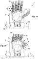
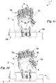
Figs. 1a-1d show an operation sequence of the robotic hand according to the invention; -
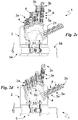
Figs. 2a-2d illustrate a further operation sequence of the robotic hand; -
Fig. 3 shows a detail of the robotic hand according to the invention; and -
Fig. 4 shows a second view of the detail inFig. 3 . - In the present document, the measures, values, shapes and geometric references (such as perpendicularity and parallelism), when associated with terms such as "about" or with other similar terms such as "almost" or "substantially", are to be understood as contemplating the possibility of measurement errors or inaccuracies due to production and/or manufacturing defects and, especially, contemplating the possibility of a slight difference in the value, measure, shape or geometric reference with which it is associated. For example, these terms, if associated with a value, preferably indicate a difference of not more than 10% of the value itself.
- Furthermore, when used, terms such as "first", "second", "higher", "lower", "main" and "secondary" do not necessarily identify an order, a priority relationship or a relative position, but can simply be used to distinguish more clearly the different components from each other.
- With reference to the aforementioned figures, the robotic hand according to the invention, as a whole, is indicated by the
numeral 1. - It is preferably capable of reproducing an anthropomorphic hand and, more preferably, a human hand.
- The
robotic hand 1 is suitable to be used in both robotic and prosthetic applications. Therobotic hand 1 comprises apalm 2 of therobotic hand 1 and a plurality of phalanges designed to reproduce the fingers, each defining its own preferred development trajectory. - In particular, the
robotic hand 1 comprises a number of phalanges so as to allow saidrobotic hand 1 to have five fingers. More in particular, therobotic hand 1 comprises, for each finger, at least onephalanx 3a proximal to thepalm 2; aphalanx 3b distal to thepalm 2 and defining the fingertip. Still more in particular, each finger of therobotic hand 1 is composed of three phalanges, i.e. twoproximal phalanges 3a, suitably positioned one after the other along the finger's preferred development trajectory, and adistal phalanx 3b. - In order to allow the
robotic hand 1 to replicate the movements of a human hand, therobotic hand 1 comprises a plurality ofhinges 4, each of which hinging a first element, coinciding with one of thephalanges palm 2 and one of thephalanges - Precisely, a
hinge 4 may be interposed between aproximal phalanx 3a and thepalm 2; between aproximal phalanx 3a and adistal phalanx 3b; and/or between twoproximal phalanges 3a. - More precisely, the
robotic hand 1 comprises fifteenhinges 4 arranged as follows: five interposed between aproximal phalanx 3a and thepalm 2, five between adjacentproximal phalanges 3a, and five between theproximal phalanx 3a and the adjacentdistal phalanx 3a. - Each
hinge 4 is adapted to define a mutual rotation axis between said first element and said second element preferably substantially perpendicular to the preferred development trajectory. - Each
hinge 4 comprises two, suitably toothed,curved surfaces 41, one of which being integral with the first element and another with the second element and adapted to reciprocally engage and slide, allowing for rotation between the first and the second element; and suitably,elastic means 42 adapted to tighten said elements relative to one another, ensuring contact between thecurved surfaces 41. - The
elastic means 42 are adapted to exert an attraction force between the first and the second element. - It is noted that the elastic means 42, as described in greater detail below, work in opposition to a closure of the hand, i.e. to an angular approach of the
phalanges phalanges - They comprise at least one, preferably two, suitably closed wire(s) connecting the first element to the second element so as to oppose to their moving away from each other. Thus, said elastic means 42 connect two
adjacent phalanges 3a and/or 3b and/or aproximal phalanx 3a to thepalm 2. - Said closed elastic loop or said elastic segment is made of elastic material and, in detail, of elastomer material.
- Each
hinge 4 lastly comprises a stopper 43 adapted to limit the angle of divergence between the first and the second element. - The stopper 43 comprises a
first tooth 431 protruding from the first element and asecond tooth 432 protruding from the second element and suitable to abut with thefirst tooth 431, limiting the rotation between the first and the second element. - In order to control the movement and, precisely, the rotation of the
phalanges hinges 4, therobotic hand 1 comprises at least oneactuating mechanism 5. - In particular, the
hand 1 may comprise asingle actuating mechanism 5 as shown in Figs. XXX. Alternatively, it comprises twoactuating mechanisms 5 capable of working and, in detail, of being controlled independently of each other. In a further alternative, therobotic hand 1 may comprise more than twoactuating mechanisms 5. - The
actuating mechanism 5 comprises, at eachhinge 4, at least afirst pulley 51 bound to the first element and at least asecond pulley 52 bound to said second element; asingle cable 53 running in all of thepulleys motor 54 adapted to act on thecable 53 by controlling the rotation of thephalanges 3a and/or 3b. - Conveniently, the
actuating mechanism 5 can additionally comprise a control unit in data exchange connection with the at least onemotor 54, allowing the operator (identifiable with a human operator or a robot\computer) to control the at least onemotor 54 and, consequently, therobotic hand 1, and a power supply of said at least one motor. - The
first pulley 51 of a hinge faces thesecond pulley 52 of the same hinge. Therefore, between thepulleys cable 53, so that the portion of thecable 53 subtended between saidpulleys - Preferably, at each
hinge 4, theactuating mechanism 5 comprises twofirst pulleys 51 bound to the first element and twosecond pulleys 52, each of which is bound to the second element and suitably facing afirst pulley 51. - Advantageously, at least one of the first 51 and
second pulleys 52 has a different friction, causing tension drops in thesingle cable 53, which are different from one another, so that thesingle cable 53 comprises subtended sectors between thepulleys hinge 4, theactuating mechanism 5 comprisespulleys - The expression having different frictions means that the
pulleys 51 and/or 52 can have different coefficients of, suitably rotational, friction on thecable 53 and/or on the element with which they are engaged. Advantageously, thepulleys 51 and/or 52 have different friction coefficients with respect to the element with which they are engaged so that at least part of thepulleys other pulleys 51 and/or 52 to the corresponding element, causing different mutual rotation speeds between the elements. - Advantageously, it is noted that the presence of
pulleys 51 and/or 52 with different frictions allows for the occurrence of a tension drop on thecable 53 and, hence, for the tension on thecable 53 to be lower at the last contact point (i.e. the separation point) on the pulley compared to that possessed by thecable 53 at the first contact point of thecable 53 on the same pulley. - In particular, this different friction is such that the
pulleys cable 53. Therefore, thecable 53 comprises sectors subtended between thepulleys phalanges
and thus transmit a distinct torque to the element, giving mutually different forces transmitted to said elements and, therefore, different mutual rotation speeds between said elements. - The different friction is such that the cable comprises sectors subtended between the pulleys, at least momentarily with a non-homogeneous tension, giving different actuation forces to said elements and different mutual rotation speeds between said elements.
- Therefore, the
pulleys 51 and/or 52 with different frictions are subjected by thecable 53 to mutually different torques and, therefore, transmit a different torque to the corresponding element. - Three of some of the possible examples wherein the
pulleys 51 and/or 52 have different friction coefficients with respect to the element with which they are engaged are described below only by way of non-limiting example. Said three examples are mutually implementable. - In a first example, the
pulleys - In a second example, the
pulleys pulleys - In a third example, the
pulleys robotic hand 1 may have different frictions since they are at least partially made of different materials so as to define a different rotational friction coefficient with respect to the element with which they are bound. - Alternatively or additionally, as anticipated above, the
pulleys cable 53 as described in the fourth example. In a fourth example, thepulleys cable 53 and, thus, the rotational friction coefficients. - It is noted that the four examples shown above may be combined with each other. Therefore, the
robotic hand 1 can havepulleys 51 and/or 52 integral with the corresponding element; pulleys 51 and/or 52 labily bound to the corresponding element with different bearing shells/bearings; pulleys 51 and/or 52 made of different materials; and/orpulleys 51 and/or 52 with different radii. - The
pulleys - The
pulleys same hinge 4 define axes substantially parallel and, particularly, substantially coincident with each other. In particular, thepulleys - The
single cable 53 advantageously connects all thepulleys phalanges palm 2. In detail, saidsingle cable 53 is in contact with all thepulleys phalanges palm 2. More in detail, saidsingle cable 53 is arranged to run in all thepulleys phalanges palm 2. - The
cable 53 is able to run individually inside all thepulleys pulley robotic hand 1. - It is made of a material having an elastic coefficient at least equal to 50 Gpa and, specifically, to 100 Gpa. It is made of a material selected from steel, PVC and a synthetic fibre such as, preferably, Dyneema (Gel Spun Polyethylene).
- The
cable 53 is open and has both the two ends engaged with the at least onemotor 54. - The
actuating mechanism 5 comprises at least twomotors 54, suitably exactly two motors, each of which is engaged at one end of thecable 53 so as to be able to selectively act, appropriately on the basis of a command of the control unit which can be given by the operator, on thecable 53, exerting thereon either two mutually equal torques/forces and, therefore, two mutually identical tensions at the two ends of thecable 53; or two distinct torques/forces and, thus, two different (in modulus and/or direction) tensions at the two ends of thecable 53. In some cases, the ability of having different tensions at the two ends of thecable 53 can be equally obtained with asingle motor 54 engaged, via distinct kinematic mechanisms, at the two ends of thecable 53, so as to be able to apply to the two ends of thecable 53 tensions that can be equal to each other or different from each other. - The control unit is able to control the two motors by varying the tension that each engine applies to the
cable 53, so as to change the mutual rotation speeds between the elements (in particular thephalanges robotic hand 1. It can therefore command themotors 54 to apply to thecable 53 tensions equal in modulus and direction and/or tensions different in at least one of the modulus and the direction. - Said tensions, according to the command given to the
motors 54, can then be either substantially equal to each other, i.e. equally orientated and with the same modulus, so as to vary the tension of thecable 53 without saidcable 53 running in thepulleys cable 53 can run in thepulleys - The
motors 54 are preferably electrical. In particular, they are servomotors i.e. motors equipped with a control board through which the motors themselves can be controlled. - The
motors 54 are integral with thepalm 2. - In order to adjust and monitor the tension applied to the
cable 53, thus the torque/output force exiting themotor 54, themechanism 5 may further comprise, for eachmotor 54, a preferably magnetic, position sensor 55, adapted to measure the position and therefore, the angular velocity of the output shaft of amotor 54. - In order to ensure contact of the
cable 53 with thefirst pulley 51, thecable 53 is adapted to define an output angle from thefirst pulley 51, preferably at least equal to 30° and, in particular, at least equal to 45°. - Said output angle is defined by the inclination of the
cable 53 with respect to the lyingplane 5a ofadjacent pulleys cable 53 on thesame pulley 51. - This
plane 5a is for the lying of the axis of afirst pulley 51 and of the axis of asecond pulley 52 located atadjacent hinges 4 and, precisely, associated with the same, suitably proximal,phalanx 3a. It should be noted that eachproximal phalanx 3a can define, for the axes of thepulleys own lying plane 5a distinct from that of the adjacent phalanx. - Similarly, in order to ensure contact of the
cable 53 with thesecond pulley 52, thecable 53 is adapted to define an input angle in the second pulley, preferably at least equal to 30° and, in particular, at least equal to 45°. - Said input angle is defined by the inclination of the
cable 53 with respect to the lyingplane 5a of the axes of thepulleys cable 53 on thesame pulley 51. - It is noted that the contact between the
cable 53 and eachpulley cable 53 so that it contacts thefirst pulley 51 of ahinge 4 on the opposite side of thesecond pulley 52 of theadjacent hinge 4 with respect to the lyingplane 5a. - Preferably, the contact between the
cable 53 and eachpulley actuating mechanism 5 comprising at least onedrive 56 for thecable 53 adapted to tilt thecable 53 with respect to the lyingplane 5a and, therefore, to define said inlet angle and/or said output angle. - In particular, the
actuating mechanism 5 comprises a plurality ofdrives 56, each of which is interposed between twoadjacent pulleys first pulley 51 of ahinge 4 and asecond pulley 52 located at theadjacent hinge 4 and, even more particularly, between thefirst pulley 51 and thesecond pulley 52 of aproximal phalanx 3a. - Each drive 56 is identifiable by a pin, a sheave or other similar element interposed between
adjacent pulleys cable 53 opposite, with respect to thesame drive 56, to that between thesame cable 53 and thepulleys cable 53, passing from afirst pulley 51 to asecond pulley 52 through thedrive 53 defines a substantially U-shaped path as shown inFig. 3 . - For example, in the case of the axis of the
drive 56 being equidistant from the axes of thepulleys drive 56 and of thepulleys drive 56 and the lyingplane 5a is at least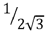
pulleys - Similar to the
pulleys robotic hand 1, there may be drives having different radii, made of a different material and/or having a different binding with respect to thephalanges 3a. Each of thephalanges pulleys 51 and/or 52 and, in particular, for at least twopulleys 51 and/or 52. The support 31 defines a housing seat suitable to at least partially accommodate thepulleys 51 and/or 52. In particular, it has a U-profile whose edges are internally engaged by thepulleys 51 and/or 52. - The support 31 can be made of a material selected from steel, PVC, aluminium.
- One or more
curved surfaces 41 are formed on the support 31. - At least one of the
first tooth 431 and thesecond tooth 432 protrudes therefrom, suitably from opposite sides along the trajectory of a finger. - In summary, for clarity, each
proximal phalanx 3a comprises a support 31 and, engaged with it, at least afirst pulley 51, at least asecond pulley 52, at least two curved surfaces of thehinge 4 and, conveniently, at least onedrive 56. Preferably, eachproximal phalanx 3a comprises twofirst pulleys 51, twosecond pulleys 52, fourcurved surfaces 41 and, conveniently, two drives 56. - Additionally, each
proximal phalanx 3a may comprise at least afirst tooth 431 and at least asecond tooth 432 protruding from the support 31, suitably from opposite sides along the trajectory of a finger. - Each
distal phalanx 3b comprises a support 31 and, engaged with it, at least afirst pulley 51, at least a curved surface of thehinge 4 and, conveniently, at least asecond tooth 432. Preferably, adistal phalanx 3b comprises twofirst pulleys 51, two curved surfaces of thehinge 4, twosecond teeth 432. - Advantageously, each
distal phalanx 3b comprises return means adapted to allow theoutput cable 53 exiting afirst pulley 51 to enter the otherfirst pulley 51. - The return means are identifiable by a sheave having an axis substantially perpendicular to the axis of the
pulleys - Similar to the
pulleys drive 56, the return means can have different frictions. Therefore, in arobotic hand 1, there may be drives having different radii, made of a different material and/or having a different binding with respect to thephalanges 3a. - The
palm 2 comprises abase body 21 with which at least five and, in particular, tensecond pulleys 52, the at least onemotor 54, preferably two motors, and tensioning means identifiable by supplementary pulleys or other similar means suitable to ensure correct tensioning of thecable 53, are engaged. - Preferably, the
palm 2 may comprise at least five and, in particular, tenfirst teeth 431 protruding from thebase body 21. - The operation of a robotic hand, described above as regards structure, is as follows. Initially, the fingers of the
robotic hand 1 are outstretched, i.e. thephalanges teeth - When grasping an object with all the fingers, the operator places the object on the
palm 2, and, via the control unit, commands themotors 54 to exert an equal torque, and therefore, an equal force on thecable 53 by changing the tension on the cable itself. - This force varies, and specifically, increases evenly the tension acting on the
cable 53 by imposing on eachpulley 51 and/or 52 a torque which depends on the friction, and conveniently, by the radii of all thepulleys hand 1. Consequently, eachpulley 51 and/or 52 transmits a different torque to thecorresponding phalanx 3a and/or 3b, causing a different rotation speed around eachhinge 4. Therefore, therobotic hand 1 closes with different speeds in thephalanges - Consequently, the
curved surfaces 41 slide mutually causing rotation of thephalanges - The grasp is completed when the torque on the
pulleys phalanges - It is noted that the elastic means 43 work in opposition to the closure of the
hand 1, and therefore to the angular approach betweenadjacent phalanges cable 53, for example, due to deactivation of themotors 54 or to a reduction in the output torque, allows the elastic means 42 to make thehand 1 go back to the initial position or at least partially go back to said initial position. - Suppose now you want to grasp an object with only some of the five fingers or making some fingers get to the object before others.
- In this case, the operator, after placing the object on the
palm 2, commands themotors 54, via the control unit, to exert different torques, and therefore different forces on the cable 53 (a condition obtainable by commanding themotors 54 to move in the opposite direction, by imposing the same direction but a different modulus, or by leaving onemotor 54 inactive). - Because of this different force exerted at its ends, the
cable 53 causes rotation of thepulleys pulleys 51 and/or 52. This difference in torque/tension is such that thepulleys phalanges Figs. 2a-2d . - The invention comprises a new design process for a
robotic hand 1 structurally and functionally described above. - This design process is characterized by a selection of frictions of the
first pulleys 51 and of thesecond pulleys 52. This selection is made in such a way that the frictions are determined so that thepulleys 51 and/or 52 cause tension drops in thesingle cable 53, which are different from one another, and so that thesingle cable 53 comprises subtended sectors between thepulleys 51 and/or 52 (suitably betweenadjacent pulleys 51 and 52), which have a non-homogeneous tension. Therefore, thecable 53, when subject to tension by the motor 53 (particularly by the at least two motors, preferably two, and appropriately with tensions at the ends which are identical and/or different) and, in particular, subject to different tensions applied by the twomotors 53, shows sectors having different tensions which give, by means of thepulleys 51 and/or 52, different actuation forces to the elements, and consequently different mutual rotation speeds between said elements. - The invention allows for significant advantages.
- A first major advantage is the ease of construction of the
robotic hand 1. - In fact, with only one
cable 53 controlled by the at least onemotor 54, therobotic hand 1 is capable of controlling the movement of eachsingle phalanx - This possibility is maximized in the case of a
robotic hand 1 with twomotors 54. In fact, in this case it is possible to move differently thevarious phalanges - This aspect has been innovatively obtained via
pulleys suitable pulleys pulleys cable 53, and hence different torques transmitted by thesame pulleys - Another advantage is therefore due to the fact that, the
robotic hand 1, by simply changing the speeds/output torques exiting themotors 54, is able to change the speeds of theindividual phalanges - This advantage is further increased by the fact that by adjusting, and in particular, by making the radii of the
pulleys phalanges phalanges robotic hand 1. - This advantage is particularly evident in the case of two motors where, due to possible operation of the
motors 54 with different speeds/output torques, this difference in radii, thanks also to the variation of the tension on thecable 53, results in a variation, suitably directly proportional to the variation of the radius, of the torque transmitted by thecable 53 to theindividual pulley cable 53 in contact with thepulley 51 and/or 52, which results in a higher static friction between said cable and said pulley, and therefore a greater torque transmitted. - It is noted that another advantage is due to the fact that the introduction of a determined friction coefficient, localized in the
pulleys cable 53, by crossing thepulleys motors 54, any effective tension may be applied to thecable 53, and hence, it is possible to differentiate from one another the actual torques on thephalanges - In summary, the effects resulting from the presence of two motors, which can be controlled by the control unit independently of each other, on the distribution of the tension on the
cable 53 entail an actual multiplicity of closure morphologies, and this gives therobotic hand 1 innovative and increased handling capabilities. - To better illustrate this advantage, a few possible basic configurations for using the
robotic hand 1 are set forth for illustrative purposes. - In a first example, both
motors 54 are actuated in a concordant way. Consequently, in therobotic hand 1, the movement of the fingers is not sequential, but simultaneous (Figs. 1a-1c ), defining a final configuration with a closure as that shown inFig. 1c . - In a second example, only a
single motor 54 is supposed to be activated, while the other is maintained fully blocked (so that it can counteract the tension of the cable without moving), thereby causing a tension distribution along the entire path of thecable 53 which will entail an initial movement of thephalanges 3a and/or 3b close to theactive motor 54 and only later a subsequent movement of the remainingphalanges Figs. 2a-2d , while the final pose obtained is illustrated inFig. 2d . - By applying a different force/torque at the two ends of the
cable 53, initially, a transitional phase of tension distribution along thecable 53, and then a sequential activation of thepulleys entire cable 53 and all thepulleys phalanges - In the transitional phase, the tension of the
cable 53 causes a sequential activation of thepulleys 51 and/or 52 according to the order of thepulleys 51 and/or 52 along the kinematic chain and with accelerations/speeds proportional to the friction of thepulleys 51 and/or 52. In detail, eachpulley 51 and/or 52 starts moving driven by a torque generated by the residual tension of thecable 53, i.e. by the tension applied by the motor to thecable 54 deprived of the tension drops caused by the different torques absorbed by the precedingpulleys pulley 51 and/or 52 that is about to be moved. - Therefore, in the second example described above and assuming we have a
cable 53 that is initially completely unloaded, the transitional phase provides that theactive motor 54 stretches the portion ofcable 53 adjacent to thesame motor 53, only causing the movement of thepulley 51/52 closest to it (according to the order of the kinematic chain). Therefore, thispulley 51/52 starts to rotate, only at this point subjecting to tension the subsequent portion ofcable 53 subtended between saidpulley 51/52 and theadjacent pulley 51/52 that only now will start to move. Consequently, thepulleys 51/52 close to theinactive engine 54 will be the last to be activated, causing the proportional and sequential closure as seen inFigs. 2a-2d . - It is obvious that by differentially activating the
motors 54, i.e. by varying the tensions at the ends of thecable 53, during the transitional phase, it is possible to diversify from one another the torques acting on theindividual pulleys robotic hand 1 and give therobotic hand 1 particular handling capabilities. In fact, the control unit, appropriately subsequent to a command given by the operator, can command a first activation of the motors 53 (for example in the same way), wherein thehand 1 grasps an object, and a second activation of the motors 53 (for example with torques having a different modulus and/or direction), wherein therobotic hand 1 handles and, for example, rotates the object. - This ability to differentiate the action of the
motors 53 also allows, at least in the transitional phase, for opposite movements between thephalanges robotic hand 1 are only partially bent, by activating the motors in mutually opposite directions, in the transitional phase, thepulleys phalanges motor 54, have speeds opposite to thepulleys phalanges other motor 54; whereas, in the steady-state phase, thepulleys phalanges - To further clarify this concept, we can consider the case of a rope rested on the ground and pulled from one end only. Initially (transitional phase), only the portion proximal to the end that is pulled will move, while the remaining portions of the rope will begin to move sequentially until (steady-state phase) the whole rope starts moving. On the other hand, in the case where the rope is pulled from both ends with opposite forces, initially (transitional phase), only the ends will move (each of which moves in accordance with the force applied thereto), whereas, in the steady-state phase, the whole rope will move in accordance with the greater of the two forces applied to the ends.
- A further advantage is the aforesaid ease of construction due to the simplicity of the
actuating mechanism 5. - It is further increased by the fact that, while the previously known robotic hands required a large number of control sensors, the
robotic hand 1 requires a maximum of two sensors 55 for controlling the twomotors 54. - Another advantage is that, since the
robotic hand 1 can be controlled thanks to the twomotors 54, an extremely simple control unit and also a low number of wires for connecting the control unit to the hand and, precisely, to themotors 54 and any sensors 55, will suffice. - Therefore, a further advantage is the smaller size of the
robotic hand 1. - A major advantage is given by the
special hinges 4 that, thanks to the presence of the elastic means 42, are able to maintain thephalanges - A no less important advantage is given by the stopper 43, which in addition to limit the angle of divergence between the first and the second element, allows said elements to be put in relation with one another. In fact, if for example two
phalanges 3a and/or 3b are mutually driven apart, the elastic means will draw said phalanges close, while theteeth - Please note that in the document a "simple" rotation of the
phalanges phalanges hinges 4 and pulleys 51 and 52, perform a double rotation, one with an axis defined by thehinges 4 and another by thepulley 51 and/or 52 thereto associated. - The invention is susceptible of variations falling within the scope of the appended claims.
Claims (11)
- A robotic hand (1) comprising- a palm (2);- a plurality of phalanges (3a, 3b) adapted to reproduce a plurality of fingers;- hinges (4) each of which hinging a first element identifying one of said phalanges (3a, 3b) to a second element identifying one among said palm (2) and one of said phalanges (3a, 3b) distinct from said first element;characterized in that it comprises at least one actuating mechanism (5) comprising- first pulleys (51), each one located at each of said hinges (4) and bound to said first element;- second pulleys (52), each one located at each of said hinges (4) and bound to said second element;- a single cable (53) running in all of said pulleys (51, 52);- at least two motors (54) adapted to apply different tensions to said cable (53);and in that- at least one of said first pulleys (51) and said second pulleys (52) has a different friction so that said pulleys (51, 52) cause tension drops in said single cable (53), which are different from one another, and hence said single cable (53) comprises subtended sectors between said pulleys (51, 52), which have a non-homogeneous tension, giving different actuation forces to said elements and consequently different mutual rotation speeds between said elements.
- A robotic hand (1) according to claim 1, wherein said cable (53) is open, defining two ends; and wherein each of said at least two motors (54) is engaged at one of said ends of said cable (53).
- A robotic hand (1) according to one or more of the preceding claims, wherein said one actuating mechanism (5) comprises two of said at least two motors (54)
- A robotic hand (1) according to one or more of the preceding claims, wherein said cable (53) is open, defining two ends; and wherein each of said two motors (54) is engaged at one of said ends of said cable (53).
- A robotic hand (1) according to one or more of the preceding claims, wherein said one actuating mechanism (5) comprises a control unit adapted to control said at least two motors (54) by varying between them the tension that each motor (54) applies to said cable (53) and therefore the mutual rotation speeds between said elements.
- A robotic hand (1) according to one or more of the preceding claims, wherein, said actuating mechanism (5) comprises said different friction pulleys (51, 52) at each one of said hinges (4).
- A robotic hand (1) according to one or more of the preceding claims, wherein said different friction pulleys (51, 52) are at least partially made of different materials.
- A robotic hand (1) according to one or more of the preceding claims, wherein said different friction pulleys (51, 52) have different radii.
- A robotic hand (1) according to one or more of the preceding claims, wherein each one of said hinges (4) comprises two curved surfaces (41), one of which being integral with said first element and another with said second element and adapted to engage with each other, allowing for rotation between said first element and said second element; and suitably, elastic means (42) adapted to tighten said elements relative to one another ensuring contact between said curved surfaces (41).
- A robotic hand (1) according to the preceding claim, wherein said elastic means (42) can be identified as a closed loop made of elastic material.
- A robotic hand (1) according to one or more of the preceding claims, comprising, for each one of said fingers, two phalanges (3a) proximal to said palm (2) and positioned one after the other; and a phalanx (3b) distal to said palm (2).
Applications Claiming Priority (2)
| Application Number | Priority Date | Filing Date | Title |
|---|---|---|---|
| ITUB2015A005328A ITUB20155328A1 (en) | 2015-11-02 | 2015-11-02 | ROBOTIC HAND |
| PCT/IB2016/056468 WO2017077429A1 (en) | 2015-11-02 | 2016-10-27 | Underactuated robotic hand |
Publications (2)
| Publication Number | Publication Date |
|---|---|
| EP3370926A1 EP3370926A1 (en) | 2018-09-12 |
| EP3370926B1 true EP3370926B1 (en) | 2019-10-16 |
Family
ID=55359655
Family Applications (1)
| Application Number | Title | Priority Date | Filing Date |
|---|---|---|---|
| EP16809523.0A Active EP3370926B1 (en) | 2015-11-02 | 2016-10-27 | Underactuated robotic hand |
Country Status (4)
| Country | Link |
|---|---|
| US (1) | US10695913B2 (en) |
| EP (1) | EP3370926B1 (en) |
| IT (1) | ITUB20155328A1 (en) |
| WO (1) | WO2017077429A1 (en) |
Cited By (1)
| Publication number | Priority date | Publication date | Assignee | Title |
|---|---|---|---|---|
| CN108818585A (en) * | 2018-07-06 | 2018-11-16 | 宣城南巡智能科技有限公司 | A kind of emulated robot palm structure |
Families Citing this family (26)
| Publication number | Priority date | Publication date | Assignee | Title |
|---|---|---|---|---|
| EP3102157B1 (en) | 2014-02-04 | 2019-04-17 | Rehabilitation Institute of Chicago | Modular and lightweight prosthesis components |
| JP1573749S (en) * | 2016-01-29 | 2017-04-10 | ||
| USD846615S1 (en) * | 2017-07-18 | 2019-04-23 | Mitsubishi Electric Corporation | Manipulator for robot |
| JP1605292S (en) * | 2017-07-18 | 2019-11-25 | ||
| USD852859S1 (en) | 2017-07-18 | 2019-07-02 | Mitsubishi Electric Corporation | Manipulator for robot |
| USD847243S1 (en) * | 2017-07-18 | 2019-04-30 | Mitsubishi Electric Corporation | Manipulator for robot |
| JP1605294S (en) * | 2017-07-18 | 2019-11-25 | ||
| JP1605291S (en) * | 2017-07-18 | 2019-11-25 | ||
| US10869773B2 (en) * | 2017-10-10 | 2020-12-22 | College Park Industries, Inc. | Prosthetic fingertip end effectors |
| JP1613980S (en) * | 2018-03-29 | 2020-03-09 | ||
| JP1613032S (en) * | 2018-03-29 | 2020-03-02 | ||
| IT201800005214A1 (en) | 2018-05-09 | 2019-11-09 | PROSTHETIC FINGER | |
| IT201800005213A1 (en) | 2018-05-09 | 2019-11-09 | UNDERACTED PROSTHETIC HAND | |
| WO2020222135A1 (en) | 2019-04-30 | 2020-11-05 | Universita' Di Pisa | A logistic device |
| US20220288771A1 (en) * | 2019-07-23 | 2022-09-15 | Auckland Uniservices Limited | An underactuated soft robotic grasping device |
| US11564815B2 (en) | 2019-09-17 | 2023-01-31 | Victoria Hand Project | Upper arm prosthetic apparatus and systems |
| USD899531S1 (en) * | 2019-09-30 | 2020-10-20 | Wen Hsien Lee | Hydraulic toy hand |
| USD1030906S1 (en) * | 2019-10-22 | 2024-06-11 | Smartivity Labs Pvt. Ltd. | Hand toy |
| US11957606B2 (en) | 2020-10-29 | 2024-04-16 | Victoria Hand Project | Low-cost prosthetic apparatus, methods, kits, and systems with improved force transfer elements |
| IT202100003821A1 (en) | 2021-02-19 | 2022-08-19 | Univ Pisa | PROCESS OF INTERACTION WITH OBJECTS |
| IT202100005099A1 (en) | 2021-03-04 | 2022-09-04 | Univ Pisa | PROSTHETIC FEEDBACK DEVICE |
| KR20230020290A (en) | 2021-08-03 | 2023-02-10 | 현대자동차주식회사 | Robot hand module |
| KR20230020292A (en) | 2021-08-03 | 2023-02-10 | 현대자동차주식회사 | Robot hand module |
| KR20230020289A (en) * | 2021-08-03 | 2023-02-10 | 현대자동차주식회사 | Robot hand module |
| WO2025068828A1 (en) | 2023-09-25 | 2025-04-03 | Università Di Pisa | Improved prosthetic feedback device |
| WO2025248439A1 (en) | 2024-05-29 | 2025-12-04 | Fondazione Istituto Italiano Di Tecnologia | Robotic joint |
Family Cites Families (11)
| Publication number | Priority date | Publication date | Assignee | Title |
|---|---|---|---|---|
| FR588700A (en) * | 1924-10-16 | 1925-05-13 | Artificial hand for amputees with or without cinematized stump | |
| US4834761A (en) * | 1985-05-09 | 1989-05-30 | Walters David A | Robotic multiple-jointed digit control system |
| US4955918A (en) * | 1989-05-30 | 1990-09-11 | University Of Southern California | Artificial dexterous hand |
| JP3086452B1 (en) * | 1999-05-19 | 2000-09-11 | 原田電子工業株式会社 | Movable finger for artificial limb, artificial hand using the movable finger, and control device for the movable finger |
| JP3486639B2 (en) * | 1999-10-26 | 2004-01-13 | 株式会社テムザック | manipulator |
| US9016744B2 (en) * | 2010-05-20 | 2015-04-28 | Ohio University | Mechanical capstan amplifier |
| WO2013185231A1 (en) * | 2012-06-13 | 2013-12-19 | Universite Laval | Underactuated anthropomorphic gripping mechanism |
| US8833827B2 (en) * | 2012-10-09 | 2014-09-16 | Willow Garage, Inc. | Kinetic and dimensional optimization for a tendon-driven gripper |
| DE102013007539A1 (en) * | 2013-05-03 | 2014-11-06 | Otto Bock Healthcare Products Gmbh | Artificial finger |
| CN103565562B (en) * | 2013-08-02 | 2014-06-04 | 华中科技大学 | Under-actuated artificial limb hand |
| US10219919B2 (en) * | 2015-08-18 | 2019-03-05 | Yale University | Multi-grasp prosthetic hand |
-
2015
- 2015-11-02 IT ITUB2015A005328A patent/ITUB20155328A1/en unknown
-
2016
- 2016-10-27 US US15/772,368 patent/US10695913B2/en active Active
- 2016-10-27 WO PCT/IB2016/056468 patent/WO2017077429A1/en not_active Ceased
- 2016-10-27 EP EP16809523.0A patent/EP3370926B1/en active Active
Non-Patent Citations (1)
| Title |
|---|
| None * |
Cited By (1)
| Publication number | Priority date | Publication date | Assignee | Title |
|---|---|---|---|---|
| CN108818585A (en) * | 2018-07-06 | 2018-11-16 | 宣城南巡智能科技有限公司 | A kind of emulated robot palm structure |
Also Published As
| Publication number | Publication date |
|---|---|
| EP3370926A1 (en) | 2018-09-12 |
| WO2017077429A1 (en) | 2017-05-11 |
| US10695913B2 (en) | 2020-06-30 |
| US20180311827A1 (en) | 2018-11-01 |
| ITUB20155328A1 (en) | 2017-05-02 |
Similar Documents
| Publication | Publication Date | Title |
|---|---|---|
| US10695913B2 (en) | Underactuated robotic hand | |
| EP2688720B1 (en) | Mobile robotic manipulator system | |
| Tincani et al. | Velvet fingers: A dexterous gripper with active surfaces | |
| US9227328B2 (en) | Variable pliability actuator | |
| Gezgin et al. | Synthesis of a Watt II six-bar linkage in the design of a hand rehabilitation robot | |
| Wang et al. | A highly-underactuated robotic hand with force and joint angle sensors | |
| KR102067869B1 (en) | Actuation of a hand intended for being provided on a humanoid robot | |
| WO2011118646A1 (en) | Robot hand and robot device | |
| IL180683A0 (en) | Drive belt actuator with drive pulleys of different circumferential speed | |
| JPH10249777A (en) | Robot arm driver and robot hand | |
| US11660150B2 (en) | Dexterous 4-DOF surgical tool for compact articulation | |
| Heidari et al. | Design and fabrication of robotic gripper for grasping in minimizing contact force | |
| EP3790513B1 (en) | An underactuated prosthetic hand | |
| Azlan et al. | Anthropomorphic finger with optimized geometric parameters for pinching and grasping tasks | |
| CN113799162A (en) | Robotic grasping gripper facing alien objects | |
| Saliba et al. | Quasi-dynamic analysis, design optimization, and evaluation of a two-finger underactuated hand | |
| An et al. | A universal robot gripper based on concentric arrays of rotating pins | |
| CN115003465B (en) | Finger assembly and manipulator comprising same | |
| JP2006198748A (en) | Joint device and mechanical universal hand using joint device | |
| Kang et al. | Design of a reconfigurable three-finger gripper for versatile grasping tasks | |
| Cho et al. | Underactuated hand with passive adaptation | |
| KR20220008432A (en) | Finger module and Griper using thereof | |
| KR100873354B1 (en) | Finger Joint Robot Hand with Switchable Joint | |
| CN117897262A (en) | Robotic Hand | |
| Obata et al. | Development of compliance actuation mechanism for wire-driven robotic hand using pressure force |
Legal Events
| Date | Code | Title | Description |
|---|---|---|---|
| STAA | Information on the status of an ep patent application or granted ep patent |
Free format text: STATUS: UNKNOWN |
|
| STAA | Information on the status of an ep patent application or granted ep patent |
Free format text: STATUS: THE INTERNATIONAL PUBLICATION HAS BEEN MADE |
|
| PUAI | Public reference made under article 153(3) epc to a published international application that has entered the european phase |
Free format text: ORIGINAL CODE: 0009012 |
|
| STAA | Information on the status of an ep patent application or granted ep patent |
Free format text: STATUS: REQUEST FOR EXAMINATION WAS MADE |
|
| 17P | Request for examination filed |
Effective date: 20180427 |
|
| AK | Designated contracting states |
Kind code of ref document: A1 Designated state(s): AL AT BE BG CH CY CZ DE DK EE ES FI FR GB GR HR HU IE IS IT LI LT LU LV MC MK MT NL NO PL PT RO RS SE SI SK SM TR |
|
| AX | Request for extension of the european patent |
Extension state: BA ME |
|
| RIN1 | Information on inventor provided before grant (corrected) |
Inventor name: CATALANO, MANUEL GIUSEPPE Inventor name: GRIOLI, GIORGIO Inventor name: DELLA SANTINA, COSIMO Inventor name: BICCHI, ANTONIO Inventor name: PIAZZA, CRISTINA Inventor name: BRANDO, ALBERTO |
|
| RIN1 | Information on inventor provided before grant (corrected) |
Inventor name: DELLA SANTINA, COSIMO Inventor name: PIAZZA, CRISTINA Inventor name: BRANDO, ALBERTO Inventor name: BICCHI, ANTONIO Inventor name: GRIOLI, GIORGIO Inventor name: CATALANO, MANUEL GIUSEPPE |
|
| DAV | Request for validation of the european patent (deleted) | ||
| DAX | Request for extension of the european patent (deleted) | ||
| REG | Reference to a national code |
Ref country code: DE Ref legal event code: R079 Ref document number: 602016022670 Country of ref document: DE Free format text: PREVIOUS MAIN CLASS: B25J0015000000 Ipc: A61F0002680000 |
|
| GRAP | Despatch of communication of intention to grant a patent |
Free format text: ORIGINAL CODE: EPIDOSNIGR1 |
|
| STAA | Information on the status of an ep patent application or granted ep patent |
Free format text: STATUS: GRANT OF PATENT IS INTENDED |
|
| RIC1 | Information provided on ipc code assigned before grant |
Ipc: B25J 15/00 20060101ALI20190524BHEP Ipc: B25J 15/02 20060101ALI20190524BHEP Ipc: A61F 2/68 20060101AFI20190524BHEP Ipc: B25J 15/08 20060101ALI20190524BHEP Ipc: A61F 2/58 20060101ALI20190524BHEP Ipc: A61F 2/70 20060101ALI20190524BHEP |
|
| INTG | Intention to grant announced |
Effective date: 20190619 |
|
| RIN1 | Information on inventor provided before grant (corrected) |
Inventor name: BICCHI, ANTONIO Inventor name: GRIOLI, GIORGIO Inventor name: PIAZZA, CRISTINA Inventor name: CATALANO, MANUEL GIUSEPPE Inventor name: BRANDO, ALBERTO Inventor name: DELLA SANTINA, COSIMO |
|
| GRAS | Grant fee paid |
Free format text: ORIGINAL CODE: EPIDOSNIGR3 |
|
| GRAA | (expected) grant |
Free format text: ORIGINAL CODE: 0009210 |
|
| STAA | Information on the status of an ep patent application or granted ep patent |
Free format text: STATUS: THE PATENT HAS BEEN GRANTED |
|
| AK | Designated contracting states |
Kind code of ref document: B1 Designated state(s): AL AT BE BG CH CY CZ DE DK EE ES FI FR GB GR HR HU IE IS IT LI LT LU LV MC MK MT NL NO PL PT RO RS SE SI SK SM TR |
|
| REG | Reference to a national code |
Ref country code: GB Ref legal event code: FG4D |
|
| REG | Reference to a national code |
Ref country code: CH Ref legal event code: EP |
|
| REG | Reference to a national code |
Ref country code: DE Ref legal event code: R096 Ref document number: 602016022670 Country of ref document: DE |
|
| REG | Reference to a national code |
Ref country code: IE Ref legal event code: FG4D |
|
| REG | Reference to a national code |
Ref country code: AT Ref legal event code: REF Ref document number: 1190566 Country of ref document: AT Kind code of ref document: T Effective date: 20191115 |
|
| REG | Reference to a national code |
Ref country code: NL Ref legal event code: MP Effective date: 20191016 |
|
| REG | Reference to a national code |
Ref country code: LT Ref legal event code: MG4D |
|
| REG | Reference to a national code |
Ref country code: AT Ref legal event code: MK05 Ref document number: 1190566 Country of ref document: AT Kind code of ref document: T Effective date: 20191016 |
|
| PG25 | Lapsed in a contracting state [announced via postgrant information from national office to epo] |
Ref country code: NL Free format text: LAPSE BECAUSE OF FAILURE TO SUBMIT A TRANSLATION OF THE DESCRIPTION OR TO PAY THE FEE WITHIN THE PRESCRIBED TIME-LIMIT Effective date: 20191016 Ref country code: SE Free format text: LAPSE BECAUSE OF FAILURE TO SUBMIT A TRANSLATION OF THE DESCRIPTION OR TO PAY THE FEE WITHIN THE PRESCRIBED TIME-LIMIT Effective date: 20191016 Ref country code: AT Free format text: LAPSE BECAUSE OF FAILURE TO SUBMIT A TRANSLATION OF THE DESCRIPTION OR TO PAY THE FEE WITHIN THE PRESCRIBED TIME-LIMIT Effective date: 20191016 Ref country code: LV Free format text: LAPSE BECAUSE OF FAILURE TO SUBMIT A TRANSLATION OF THE DESCRIPTION OR TO PAY THE FEE WITHIN THE PRESCRIBED TIME-LIMIT Effective date: 20191016 Ref country code: LT Free format text: LAPSE BECAUSE OF FAILURE TO SUBMIT A TRANSLATION OF THE DESCRIPTION OR TO PAY THE FEE WITHIN THE PRESCRIBED TIME-LIMIT Effective date: 20191016 Ref country code: BG Free format text: LAPSE BECAUSE OF FAILURE TO SUBMIT A TRANSLATION OF THE DESCRIPTION OR TO PAY THE FEE WITHIN THE PRESCRIBED TIME-LIMIT Effective date: 20200116 Ref country code: NO Free format text: LAPSE BECAUSE OF FAILURE TO SUBMIT A TRANSLATION OF THE DESCRIPTION OR TO PAY THE FEE WITHIN THE PRESCRIBED TIME-LIMIT Effective date: 20200116 Ref country code: GR Free format text: LAPSE BECAUSE OF FAILURE TO SUBMIT A TRANSLATION OF THE DESCRIPTION OR TO PAY THE FEE WITHIN THE PRESCRIBED TIME-LIMIT Effective date: 20200117 Ref country code: PL Free format text: LAPSE BECAUSE OF FAILURE TO SUBMIT A TRANSLATION OF THE DESCRIPTION OR TO PAY THE FEE WITHIN THE PRESCRIBED TIME-LIMIT Effective date: 20191016 Ref country code: FI Free format text: LAPSE BECAUSE OF FAILURE TO SUBMIT A TRANSLATION OF THE DESCRIPTION OR TO PAY THE FEE WITHIN THE PRESCRIBED TIME-LIMIT Effective date: 20191016 Ref country code: PT Free format text: LAPSE BECAUSE OF FAILURE TO SUBMIT A TRANSLATION OF THE DESCRIPTION OR TO PAY THE FEE WITHIN THE PRESCRIBED TIME-LIMIT Effective date: 20200217 |
|
| PG25 | Lapsed in a contracting state [announced via postgrant information from national office to epo] |
Ref country code: RS Free format text: LAPSE BECAUSE OF FAILURE TO SUBMIT A TRANSLATION OF THE DESCRIPTION OR TO PAY THE FEE WITHIN THE PRESCRIBED TIME-LIMIT Effective date: 20191016 Ref country code: HR Free format text: LAPSE BECAUSE OF FAILURE TO SUBMIT A TRANSLATION OF THE DESCRIPTION OR TO PAY THE FEE WITHIN THE PRESCRIBED TIME-LIMIT Effective date: 20191016 Ref country code: IS Free format text: LAPSE BECAUSE OF FAILURE TO SUBMIT A TRANSLATION OF THE DESCRIPTION OR TO PAY THE FEE WITHIN THE PRESCRIBED TIME-LIMIT Effective date: 20200224 |
|
| REG | Reference to a national code |
Ref country code: CH Ref legal event code: PL |
|
| PG25 | Lapsed in a contracting state [announced via postgrant information from national office to epo] |
Ref country code: AL Free format text: LAPSE BECAUSE OF FAILURE TO SUBMIT A TRANSLATION OF THE DESCRIPTION OR TO PAY THE FEE WITHIN THE PRESCRIBED TIME-LIMIT Effective date: 20191016 |
|
| REG | Reference to a national code |
Ref country code: DE Ref legal event code: R097 Ref document number: 602016022670 Country of ref document: DE |
|
| PG2D | Information on lapse in contracting state deleted |
Ref country code: IS |
|
| PG25 | Lapsed in a contracting state [announced via postgrant information from national office to epo] |
Ref country code: RO Free format text: LAPSE BECAUSE OF FAILURE TO SUBMIT A TRANSLATION OF THE DESCRIPTION OR TO PAY THE FEE WITHIN THE PRESCRIBED TIME-LIMIT Effective date: 20191016 Ref country code: CZ Free format text: LAPSE BECAUSE OF FAILURE TO SUBMIT A TRANSLATION OF THE DESCRIPTION OR TO PAY THE FEE WITHIN THE PRESCRIBED TIME-LIMIT Effective date: 20191016 Ref country code: EE Free format text: LAPSE BECAUSE OF FAILURE TO SUBMIT A TRANSLATION OF THE DESCRIPTION OR TO PAY THE FEE WITHIN THE PRESCRIBED TIME-LIMIT Effective date: 20191016 Ref country code: LU Free format text: LAPSE BECAUSE OF NON-PAYMENT OF DUE FEES Effective date: 20191027 Ref country code: DK Free format text: LAPSE BECAUSE OF FAILURE TO SUBMIT A TRANSLATION OF THE DESCRIPTION OR TO PAY THE FEE WITHIN THE PRESCRIBED TIME-LIMIT Effective date: 20191016 Ref country code: CH Free format text: LAPSE BECAUSE OF NON-PAYMENT OF DUE FEES Effective date: 20191031 Ref country code: ES Free format text: LAPSE BECAUSE OF FAILURE TO SUBMIT A TRANSLATION OF THE DESCRIPTION OR TO PAY THE FEE WITHIN THE PRESCRIBED TIME-LIMIT Effective date: 20191016 Ref country code: LI Free format text: LAPSE BECAUSE OF NON-PAYMENT OF DUE FEES Effective date: 20191031 Ref country code: MC Free format text: LAPSE BECAUSE OF FAILURE TO SUBMIT A TRANSLATION OF THE DESCRIPTION OR TO PAY THE FEE WITHIN THE PRESCRIBED TIME-LIMIT Effective date: 20191016 Ref country code: IS Free format text: LAPSE BECAUSE OF FAILURE TO SUBMIT A TRANSLATION OF THE DESCRIPTION OR TO PAY THE FEE WITHIN THE PRESCRIBED TIME-LIMIT Effective date: 20200216 |
|
| REG | Reference to a national code |
Ref country code: BE Ref legal event code: MM Effective date: 20191031 |
|
| PLBE | No opposition filed within time limit |
Free format text: ORIGINAL CODE: 0009261 |
|
| STAA | Information on the status of an ep patent application or granted ep patent |
Free format text: STATUS: NO OPPOSITION FILED WITHIN TIME LIMIT |
|
| PG25 | Lapsed in a contracting state [announced via postgrant information from national office to epo] |
Ref country code: BE Free format text: LAPSE BECAUSE OF NON-PAYMENT OF DUE FEES Effective date: 20191031 Ref country code: SK Free format text: LAPSE BECAUSE OF FAILURE TO SUBMIT A TRANSLATION OF THE DESCRIPTION OR TO PAY THE FEE WITHIN THE PRESCRIBED TIME-LIMIT Effective date: 20191016 Ref country code: SM Free format text: LAPSE BECAUSE OF FAILURE TO SUBMIT A TRANSLATION OF THE DESCRIPTION OR TO PAY THE FEE WITHIN THE PRESCRIBED TIME-LIMIT Effective date: 20191016 |
|
| 26N | No opposition filed |
Effective date: 20200717 |
|
| PG25 | Lapsed in a contracting state [announced via postgrant information from national office to epo] |
Ref country code: IE Free format text: LAPSE BECAUSE OF NON-PAYMENT OF DUE FEES Effective date: 20191027 |
|
| PG25 | Lapsed in a contracting state [announced via postgrant information from national office to epo] |
Ref country code: SI Free format text: LAPSE BECAUSE OF FAILURE TO SUBMIT A TRANSLATION OF THE DESCRIPTION OR TO PAY THE FEE WITHIN THE PRESCRIBED TIME-LIMIT Effective date: 20191016 |
|
| PG25 | Lapsed in a contracting state [announced via postgrant information from national office to epo] |
Ref country code: CY Free format text: LAPSE BECAUSE OF FAILURE TO SUBMIT A TRANSLATION OF THE DESCRIPTION OR TO PAY THE FEE WITHIN THE PRESCRIBED TIME-LIMIT Effective date: 20191016 |
|
| PG25 | Lapsed in a contracting state [announced via postgrant information from national office to epo] |
Ref country code: HU Free format text: LAPSE BECAUSE OF FAILURE TO SUBMIT A TRANSLATION OF THE DESCRIPTION OR TO PAY THE FEE WITHIN THE PRESCRIBED TIME-LIMIT; INVALID AB INITIO Effective date: 20161027 Ref country code: MT Free format text: LAPSE BECAUSE OF FAILURE TO SUBMIT A TRANSLATION OF THE DESCRIPTION OR TO PAY THE FEE WITHIN THE PRESCRIBED TIME-LIMIT Effective date: 20191016 |
|
| PG25 | Lapsed in a contracting state [announced via postgrant information from national office to epo] |
Ref country code: TR Free format text: LAPSE BECAUSE OF FAILURE TO SUBMIT A TRANSLATION OF THE DESCRIPTION OR TO PAY THE FEE WITHIN THE PRESCRIBED TIME-LIMIT Effective date: 20191016 |
|
| PG25 | Lapsed in a contracting state [announced via postgrant information from national office to epo] |
Ref country code: MK Free format text: LAPSE BECAUSE OF FAILURE TO SUBMIT A TRANSLATION OF THE DESCRIPTION OR TO PAY THE FEE WITHIN THE PRESCRIBED TIME-LIMIT Effective date: 20191016 |
|
| P01 | Opt-out of the competence of the unified patent court (upc) registered |
Effective date: 20230607 |
|
| PGFP | Annual fee paid to national office [announced via postgrant information from national office to epo] |
Ref country code: FR Payment date: 20241025 Year of fee payment: 9 |
|
| PGFP | Annual fee paid to national office [announced via postgrant information from national office to epo] |
Ref country code: IT Payment date: 20250717 Year of fee payment: 10 |
|
| PGFP | Annual fee paid to national office [announced via postgrant information from national office to epo] |
Ref country code: DE Payment date: 20251020 Year of fee payment: 10 |
|
| PGFP | Annual fee paid to national office [announced via postgrant information from national office to epo] |
Ref country code: GB Payment date: 20251024 Year of fee payment: 10 |