EP3370228A1 - Laminated plyboard for musical instrument, method for manufacturing the same, and musical instrument - Google Patents
Laminated plyboard for musical instrument, method for manufacturing the same, and musical instrument Download PDFInfo
- Publication number
- EP3370228A1 EP3370228A1 EP17210513.2A EP17210513A EP3370228A1 EP 3370228 A1 EP3370228 A1 EP 3370228A1 EP 17210513 A EP17210513 A EP 17210513A EP 3370228 A1 EP3370228 A1 EP 3370228A1
- Authority
- EP
- European Patent Office
- Prior art keywords
- laminated
- layer
- plyboard
- layer portion
- musical instrument
- Prior art date
- Legal status (The legal status is an assumption and is not a legal conclusion. Google has not performed a legal analysis and makes no representation as to the accuracy of the status listed.)
- Granted
Links
Images


Classifications
-
- G—PHYSICS
- G10—MUSICAL INSTRUMENTS; ACOUSTICS
- G10D—STRINGED MUSICAL INSTRUMENTS; WIND MUSICAL INSTRUMENTS; ACCORDIONS OR CONCERTINAS; PERCUSSION MUSICAL INSTRUMENTS; AEOLIAN HARPS; SINGING-FLAME MUSICAL INSTRUMENTS; MUSICAL INSTRUMENTS NOT OTHERWISE PROVIDED FOR
- G10D13/00—Percussion musical instruments; Details or accessories therefor
- G10D13/01—General design of percussion musical instruments
- G10D13/02—Drums; Tambourines with drumheads
-
- G—PHYSICS
- G10—MUSICAL INSTRUMENTS; ACOUSTICS
- G10D—STRINGED MUSICAL INSTRUMENTS; WIND MUSICAL INSTRUMENTS; ACCORDIONS OR CONCERTINAS; PERCUSSION MUSICAL INSTRUMENTS; AEOLIAN HARPS; SINGING-FLAME MUSICAL INSTRUMENTS; MUSICAL INSTRUMENTS NOT OTHERWISE PROVIDED FOR
- G10D13/00—Percussion musical instruments; Details or accessories therefor
- G10D13/10—Details of, or accessories for, percussion musical instruments
- G10D13/22—Shells
-
- B—PERFORMING OPERATIONS; TRANSPORTING
- B32—LAYERED PRODUCTS
- B32B—LAYERED PRODUCTS, i.e. PRODUCTS BUILT-UP OF STRATA OF FLAT OR NON-FLAT, e.g. CELLULAR OR HONEYCOMB, FORM
- B32B1/00—Layered products having a non-planar shape
- B32B1/08—Tubular products
-
- B—PERFORMING OPERATIONS; TRANSPORTING
- B32—LAYERED PRODUCTS
- B32B—LAYERED PRODUCTS, i.e. PRODUCTS BUILT-UP OF STRATA OF FLAT OR NON-FLAT, e.g. CELLULAR OR HONEYCOMB, FORM
- B32B21/00—Layered products comprising a layer of wood, e.g. wood board, veneer, wood particle board
- B32B21/04—Layered products comprising a layer of wood, e.g. wood board, veneer, wood particle board comprising wood as the main or only constituent of a layer, which is next to another layer of the same or of a different material
- B32B21/042—Layered products comprising a layer of wood, e.g. wood board, veneer, wood particle board comprising wood as the main or only constituent of a layer, which is next to another layer of the same or of a different material of wood
-
- B—PERFORMING OPERATIONS; TRANSPORTING
- B32—LAYERED PRODUCTS
- B32B—LAYERED PRODUCTS, i.e. PRODUCTS BUILT-UP OF STRATA OF FLAT OR NON-FLAT, e.g. CELLULAR OR HONEYCOMB, FORM
- B32B21/00—Layered products comprising a layer of wood, e.g. wood board, veneer, wood particle board
- B32B21/13—Layered products comprising a layer of wood, e.g. wood board, veneer, wood particle board all layers being exclusively wood
-
- B—PERFORMING OPERATIONS; TRANSPORTING
- B32—LAYERED PRODUCTS
- B32B—LAYERED PRODUCTS, i.e. PRODUCTS BUILT-UP OF STRATA OF FLAT OR NON-FLAT, e.g. CELLULAR OR HONEYCOMB, FORM
- B32B21/00—Layered products comprising a layer of wood, e.g. wood board, veneer, wood particle board
- B32B21/14—Layered products comprising a layer of wood, e.g. wood board, veneer, wood particle board comprising wood board or veneer
-
- B—PERFORMING OPERATIONS; TRANSPORTING
- B32—LAYERED PRODUCTS
- B32B—LAYERED PRODUCTS, i.e. PRODUCTS BUILT-UP OF STRATA OF FLAT OR NON-FLAT, e.g. CELLULAR OR HONEYCOMB, FORM
- B32B7/00—Layered products characterised by the relation between layers; Layered products characterised by the relative orientation of features between layers, or by the relative values of a measurable parameter between layers, i.e. products comprising layers having different physical, chemical or physicochemical properties; Layered products characterised by the interconnection of layers
- B32B7/04—Interconnection of layers
- B32B7/12—Interconnection of layers using interposed adhesives or interposed materials with bonding properties
-
- G—PHYSICS
- G10—MUSICAL INSTRUMENTS; ACOUSTICS
- G10D—STRINGED MUSICAL INSTRUMENTS; WIND MUSICAL INSTRUMENTS; ACCORDIONS OR CONCERTINAS; PERCUSSION MUSICAL INSTRUMENTS; AEOLIAN HARPS; SINGING-FLAME MUSICAL INSTRUMENTS; MUSICAL INSTRUMENTS NOT OTHERWISE PROVIDED FOR
- G10D13/00—Percussion musical instruments; Details or accessories therefor
-
- G—PHYSICS
- G10—MUSICAL INSTRUMENTS; ACOUSTICS
- G10D—STRINGED MUSICAL INSTRUMENTS; WIND MUSICAL INSTRUMENTS; ACCORDIONS OR CONCERTINAS; PERCUSSION MUSICAL INSTRUMENTS; AEOLIAN HARPS; SINGING-FLAME MUSICAL INSTRUMENTS; MUSICAL INSTRUMENTS NOT OTHERWISE PROVIDED FOR
- G10D13/00—Percussion musical instruments; Details or accessories therefor
- G10D13/10—Details of, or accessories for, percussion musical instruments
- G10D13/24—Material for manufacturing percussion musical instruments; Treatment of the material
-
- B—PERFORMING OPERATIONS; TRANSPORTING
- B32—LAYERED PRODUCTS
- B32B—LAYERED PRODUCTS, i.e. PRODUCTS BUILT-UP OF STRATA OF FLAT OR NON-FLAT, e.g. CELLULAR OR HONEYCOMB, FORM
- B32B2250/00—Layers arrangement
- B32B2250/40—Symmetrical or sandwich layers, e.g. ABA, ABCBA, ABCCBA
-
- B—PERFORMING OPERATIONS; TRANSPORTING
- B32—LAYERED PRODUCTS
- B32B—LAYERED PRODUCTS, i.e. PRODUCTS BUILT-UP OF STRATA OF FLAT OR NON-FLAT, e.g. CELLULAR OR HONEYCOMB, FORM
- B32B2255/00—Coating on the layer surface
- B32B2255/08—Coating on the layer surface on wood layer
-
- B—PERFORMING OPERATIONS; TRANSPORTING
- B32—LAYERED PRODUCTS
- B32B—LAYERED PRODUCTS, i.e. PRODUCTS BUILT-UP OF STRATA OF FLAT OR NON-FLAT, e.g. CELLULAR OR HONEYCOMB, FORM
- B32B2307/00—Properties of the layers or laminate
- B32B2307/50—Properties of the layers or laminate having particular mechanical properties
Definitions
- the present invention relates to a laminated plyboard for a musical instrument used for a shell of a drum and the like, a method for manufacturing the laminated plyboard for the musical instrument, and a musical instrument such as a drum.
- the laminated plyboard is used for the musical instrument such as drums, for example.
- the laminated plyboard is employed for a shell (drum body) over which a drum head is stretched.
- the laminated plyboard used for a shell many layers of the laminated plyboard are made of wood because a warm sound can be obtained in terms of sound quality.
- a polygonal body is formed using a wood-based material or a non-wood-based material as the material for the body.
- the internal veneer is held by the plyboard having high specific gravity from an outside thereof and thus an energy loss is large due to internal friction of vibration energy. Therefore, there is a problem that attenuation is too fast when applied to a drum and the sound volume tends to become relatively small.
- a drum body is made of a plyboard having an internal veneer having high specific gravity (high rigidity) arranged in its central portion , the internal veneer held by outer veneers having lower specific gravity (lower rigidity) toward outside.
- Japanese Laid-open Patent Publication(Kokai) No. 11-45087 A the shell has a polygonal structure and thus the stretched structure of the drum head has a special structure, and a typical head frame cannot be used.
- Japanese Laid-open Patent Publication(Kokai) No. 2009-163112 A all veneers of the plyboard of the drum body are made of wood, and thus the cost becomes high.
- the internal veneer has high specific gravity, and the wood with high specific gravity is difficult to obtain and expensive, or in some cases, transaction is restricted. Therefore, there is a problem that decreasing the loss of vibration energy due to internal friction while suppressing an increase in the cost and securing high rigidity is not easy.
- the present invention provides a laminated plyboard for a musical instrument, a method for manufacturing the same, and a musical instrument that reduce a loss of vibration energy due to internal friction while securing high rigidity with inexpensive cost.
- a first aspect of the present invention provides a laminated plyboard for a musical instrument, the laminated plyboard including a first layer portion having at least one layer, a second layer portion having at least one layer, and an impregnated layer impregnated with phenol and sandwiched between the first layer portion and the second layer portion, wherein a rigidity coefficient of the impregnated layer is higher than rigidity coefficients of the layers that configure the first layer portion and the second layer portion.
- a second aspect of the present invention provides a musical instrument including the above-described laminated plyboard for a musical instrument.
- the loss of vibration energy due to internal friction can be reduced while high rigidity is secured with inexpensive cost.
- a sound without distortion can be realized.
- manufacturing by gluing is easy.
- the loss of vibration energy due to internal friction can be reduced while high rigidity is secured, and favorable sound characteristics can be obtained, with inexpensive cost.
- FIG. 1A is an external perspective view of a drum to which a laminated plyboard for a musical instrument according to an embodiment of the present invention is applied.
- a drum 10 in FIG. 1A is, for example, a snare drum.
- the drum 10 includes a shell 12 that is a drum body formed into a cylindrical shape with both ends open, and two drum heads 13 (only a back-side drum head is shown) stretched to cover both the openings of the shell 12.
- the drum heads 13 on the front and back sides are supported by a head support tension portion 14.
- a drum sound line 15 is stretched over the drum head 13 on the back side.
- the drum sound line 15 is selectively in contact with and separated from the drum head 13 on the back side by a backend mechanism 16 or the like.
- FIG. 1B is a perspective view of the shell 12.
- FIG. 2A is a partial longitudinal sectional view of the shell 12.
- a laminated plyboard 20 is used for a principal part of the shell 12.
- the laminated plyboard 20 is annularly deformed according to the shape of the shell 12 and used.
- a decorative plyboard 22 is glued on an outer peripheral surface side of the laminated plyboard 20, and a decorative plyboard 23 is glued on an inner peripheral surface side of the laminated plyboard 20.
- An outer peripheral surface of the decorative plyboard 22 serves as an outer peripheral surface 12a of the shell 12 and an inner peripheral surface of the decorative plyboard 23 serves as an inner peripheral surface 12b of the shell 12.
- the laminated plyboard 20 has a three-layer structure in which an impregnated layer 21 impregnated with phenol is sandwiched and laminated between a first layer portion S1 and a second layer portion S2. Therefore, both the first layer portion S1 and the second layer portion S2 are veneers, and the second layer portion S2 is laminated on an opposite side of the first layer portion S1 across the impregnated layer 21.
- the impregnated layer 21 is formed by impregnating a phenol resin into a base material such as a paper.
- the specific gravity of the impregnated layer 21 is 1.0 to 2.0 and is about 1.2, for example, and the thickness thereof is about 0.8 mm, for example.
- the specific gravity of the impregnated layer 21 is larger than that of Jatoba (specific gravity: 0.9) of wood.
- the material of the first layer portion S1 and the second layer portion S2 is common natural wood.
- wood having smaller specific gravity than the impregnated layer 21, and wood having specific gravity of 0.7 to 0.4 is selected, for example.
- Specific examples thereof include maple (specific gravity: 0.7), poplar (specific gravity: 0.45), birch (specific gravity: 0.71), mahogany (specific gravity: 0.65), and meranti (specific gravity: 0.55).
- the elastic coefficient (Pa) and the rigidity coefficient (Pa) of the impregnated layer 21 are higher than those of the layer portions S1 and S2.
- each of the layer portions S1 and S2 has a single-layer structure, and thus the elastic coefficient and the rigidity coefficient of the material of the layer portions S1 and S2 are reflected to directly the layer portions S1 and S2.
- the first layer portion S1 and the second layer portion S2 are common in the thickness, and the thickness is 0.9 mm, for example.
- an axis passing through the center of the impregnated layer 21 in the thickness direction and perpendicular to the thickness direction is defined as a central axis C.
- the laminated plyboard 20 has symmetrical structure about the central axis C in a plate status before being deformed for the shell 12.
- the central axis C is parallel to an axial direction of the shell 12.
- a distance L1 from the central axis C to an end surface of the first layer portion S1 and a distance L2 from the central axis C to an end surface of the second layer portion S2 are approximately equal in the thickness direction of the impregnated layer 21.
- the bending rigidity (EI: E is a Young' s coefficient and I is a geometrical moment of area) (Pa ⁇ m 4 ) of the first layer portion S1 with respect to the central axis C and the bending rigidity of the second layer portion S2 with respect to the central axis C are approximately equal.
- the bending rigidity referred here is bending rigidity with respect to the central axis C of when each of the first layer portion S1 and the second layer portion S2 is regarded as a beam.
- the central axis C corresponds to a neutral axis of the beam.
- each of the decorative plyboard 22 and 23 has a two-layer structure of wood, for example.
- the specific gravity (or density) of the impregnated layer 21 sandwiched between the layer portions S1 and S2 is larger than that of the layer portions S1 and S2, and the elastic coefficient and the rigidity coefficient of the impregnated layer 21 are higher than those of the layer portions S1 and S2.
- the laminated plyboard 20 includes the highly rigid impregnated layer 21 in its center, the total rigidity of the laminated plyboard 20 is also high.
- the surface of the phenol resin is smoother and more homogeneous than a surface of wood, and is thus generally used as an outermost surface of a laminated material as a material to which a decorative paper (plate) etc. is glued and paint is applied.
- the impregnated layer 21 is sandwiched and laminated between wood having lower rigidity coefficient (smaller specific gravity) than the impregnated layer 21, thereby to realize high rigidity and decrease in the energy loss.
- first layer portion S1 and the second layer portion S2 are approximately equal to each other in the bending rigidity with respect to the central axis C. Therefore, vibration is similarly transmitted to both sides in the thickness direction of the impregnated layer 21. As a result, natural vibration characteristics and acoustic characteristics can be obtained, instead of generating a sound with distortion including a specific frequency component having a level difference. Also, while wood with high specific gravity is difficult to obtain and expensive, the impregnated layer 21 impregnated with phenol is inexpensive and easy to manufacture.
- the rigidity coefficient of the impregnated layer 21 is higher than those of the layer portions S1 and S2. Therefore, the loss of vibration energy due to internal friction can be reduced while high rigidity is secured with inexpensive cost.
- the laminated plyboard 20 to the shell 12, good acoustic characteristics can be obtained.
- first layer portion S1 and the second layer portion S2 are common in the thickness and the material, are symmetrical in the arrangement about the central axis C, and are approximately common in the bending rigidity with respect to the central axis C. With the configuration, a sound without distortion can be realized. In addition, since each of the layer portions S1 and S2 is formed of a single layer, the structure is simple and manufacturing is easy.
- the number of the laminated plyboard 20 is not limited to one, and two of the laminated plyboard 20 may be stacked and used, as shown in FIG. 2B . It should be noted that the number of the laminated plyboard 20 to be stacked is not limited.
- the layer portions S1 and S2 that sandwich the impregnated layer 21 are approximately the same in the thickness and the material and are formed of single layer in the laminated plyboard 20.
- each of the layer portions S1 and S2 may be formed of at least one layer, and different materials or layers having different thicknesses may be employed between the layer portions S1 and S2. Variations will be described with reference to FIGS. 3A to 3C .
- FIGS. 3A to 3C are partial longitudinal sectional views of a shell 12 using laminated plyboard 20 according to one of first to third variations.
- a first layer portion S1 has a two-layer structure in which layers 24 and 25 are laminated
- a second layer portion S2 has a two-layer structure in which layers 26 and 27 are laminated. All the layers 24, 25, 26, and 27 are wood.
- the thickness of the first layer portion S1 and the thickness of the second layer portion S2 are common.
- the specific gravity of an impregnated layer 21 is larger than the specific gravity of any of the layers 24 and 25 that configure the first layer portion S1 and the layers 26 and 27 that configure the second layer portion S2. Further, the rigidity coefficient and elastic coefficient of the impregnated layer 21 are higher than those of the layers 24 to 27. Further, the bending rigidity of the first layer portion S1 with respect to a central axis C is approximately equal to the bending rigidity of the second layer portion S2 with respect to the central axis C.
- the thickness and arrangement of the layers that configure the first layer portion S1 and the thickness and arrangement of the layer that configure the second layer portion S2 are symmetrical about the central axis C.
- the layers 25 and 26, and the layers 24 and 27, which are layers arranged at symmetrical positions about the central axis C, are the same in the thickness and material. With the configuration, a similar effect to the example of FIG. 2A is exhibited in terms of realization of a sound without distortion.
- the bending rigidity of the first layer portion S1 with respect to the central axis C and the bending rigidity of the second layer portion S2 with respect to the central axis C are made approximately equal, whereby the effect to reduce the loss of vibration energy due to internal friction to obtain favorably acoustic characteristics can be obtained. Therefore, it is not indispensable that the structure of the laminated plyboard 20 is symmetrical about the central axis C.
- the first layer portion S1 may have a two-layer structure in which the layers 24 and 25 are laminated, and the second layer portion S2 may have a single-layer structure.
- the bending rigidity of the first layer portion S1 about the central axis C has been adjusted to be approximately equal to the bending rigidity of the second layer portion S2.
- the bending rigidity of the first layer portion S1 depends on the material and thickness of the wood to be applied to the layers 24, 25, and means the bending rigidity of the first layer portion S1 as a whole. It should be noted that, strictly speaking, an adhesive that glues the layers 24 and 25 also affects the bending rigidity.
- the first layer portion S1 may have a three-layer structure in which layers 28, 29, and 30 are laminated, and the second layer portion S2 may have a single-layer structure.
- the first layer portion S1 and the second layer portion S2 are different not only in the number of layers to configure but also in the thickness.
- the distance L1 from the central axis C to the end surface of the first layer portion S1 and the distance L2 from the central axis C to the end surface of the second layer portion S2 do not accord.
- the thickness and material of each of the layers 28, 29, and 30 and the second layer portion S2 are selected.
- any of the laminated plyboard 20 in FIGS. 3A to 3C can be applied to the configuration in which the plural laminated plyboards 20 as shown in FIG. 2B are stacked.
- the impregnated layer 21 is not limited to a veneer configuration, and may have a configuration in which a plurality of layers impregnated with phenol is stacked.
- the impregnated layer 21 in the present invention may include a thin layer or an adhesive layer other than the layer impregnated with phenol. For example, one obtained by stretching and bonding a decorative paper over a phenol resin laminate may be treated as the impregnated layer 21.
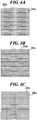
- the layer 24 and the layer 25 may be laminated such that wood grain 24a of the layer 24 and wood grain 25a of the layer 25 are shifted from each other when the laminated plyboard 20 is viewed along the arrow in FIG. 3A ( FIG. 4A ).
- the wood grain 24a of the layer 24 is shown by the solid line and the wood grain 25a of the layer 25 is shown by the broken line.
- wood has the highest bending rigidity along the wood grain.
- the overall rigidity of the laminated plyboard 20 can be increased as the angle between the wood grain 24a of the layer 24 and the wood grain 25a of the layer 25 is increased.
- the wood grain 24a and the wood grain 25a are shifted from each other by 90° ( FIG. 4C )
- the overall rigidity of the laminated plyboard 20 can be maximized.
- the layer 24 is arranged such that the wood grain 24a of the layer 24, which is positioned outside the layer 25 and attracts people's attention, goes along a peripheral direction of the shell 12, a favorable sense of beauty for a viewer can be provided.
- the laminated plyboard 20 is applicable not only to the snare drum but also to various types of percussion instrument such as a bass drum and a tom-tom. Further, the present invention is not limited to the drums and may be applied to parts related to sound in musical instruments. For example, the present invention may be applied to a body (a front plate, a back plate and/or a side plate) of a guitar, a side plate of a piano, or the like. Further, although the laminated plyboard 20 is configured as laminated plyboard for musical instruments, the laminated plyboard 20 can also be applied to various other uses other than the musical instrument.
Landscapes
- Engineering & Computer Science (AREA)
- Physics & Mathematics (AREA)
- Acoustics & Sound (AREA)
- Multimedia (AREA)
- Life Sciences & Earth Sciences (AREA)
- Wood Science & Technology (AREA)
- Mechanical Engineering (AREA)
- Stringed Musical Instruments (AREA)
- Laminated Bodies (AREA)
Abstract
Description
- The present invention relates to a laminated plyboard for a musical instrument used for a shell of a drum and the like, a method for manufacturing the laminated plyboard for the musical instrument, and a musical instrument such as a drum.
- Conventionally, various types of a laminated plyboard for a musical instrument are known, and the laminated plyboard is used for the musical instrument such as drums, for example. In the drum, for example, the laminated plyboard is employed for a shell (drum body) over which a drum head is stretched. As the laminated plyboard used for a shell, many layers of the laminated plyboard are made of wood because a warm sound can be obtained in terms of sound quality.
- In a drum described in Japanese Laid-open Patent Publication (Kokai) No.
11-45087 A 2009-163112 A - However, in Japanese Laid-open Patent Publication(Kokai) No.
11-45087 A 2009-163112 A - The present invention provides a laminated plyboard for a musical instrument, a method for manufacturing the same, and a musical instrument that reduce a loss of vibration energy due to internal friction while securing high rigidity with inexpensive cost.
- Accordingly, a first aspect of the present invention provides a laminated plyboard for a musical instrument, the laminated plyboard including a first layer portion having at least one layer, a second layer portion having at least one layer, and an impregnated layer impregnated with phenol and sandwiched between the first layer portion and the second layer portion, wherein a rigidity coefficient of the impregnated layer is higher than rigidity coefficients of the layers that configure the first layer portion and the second layer portion.
- Accordingly, a second aspect of the present invention provides a musical instrument including the above-described laminated plyboard for a musical instrument.
- According to the first aspect of the present invention, the loss of vibration energy due to internal friction can be reduced while high rigidity is secured with inexpensive cost.
- According to the first aspect of the present invention, a sound without distortion can be realized. In addition, according to the first aspect of the present invention, manufacturing by gluing is easy.
- According to the second aspect of the present invention, the loss of vibration energy due to internal friction can be reduced while high rigidity is secured, and favorable sound characteristics can be obtained, with inexpensive cost.
- Further features of the present invention will become apparent from the following description of exemplary embodiments (with reference to the attached drawings).
-
-
FIG. 1A is an external perspective view of a drum to which a laminated plyboard for a musical instrument according to an embodiment of the present invention is applied; -
FIG. 1B is a perspective view of a shell provided in the drum ofFIG. 1A ; -
FIG. 2A is a partial longitudinal sectional view of the shell; -
FIG. 2B is a partial longitudinal sectional view of the shell in which two layers of a laminated plyboard are stacked; -
FIG. 3A is a partial longitudinal sectional view of a shell using a laminated plyboard according to a first variation; -
FIG. 3B is a partial longitudinal sectional view of a shell using a laminated plyboard according to a second variation; -
FIG. 3C is a partial longitudinal sectional view of a shell using a laminated plyboard according to a third variation; -
FIG. 4A is a view indicating a first variation of a method for laminating two layers in the laminated plyboard; -
FIG. 4B is a view indicating a second variation of a method for laminating two layers in the laminated plyboard; and -
FIG. 4C is a view indicating a third variation of a method for laminating two layers in the laminated plyboard. - Hereinafter, embodiments of the present invention will be described with reference to the drawings.
-
FIG. 1A is an external perspective view of a drum to which a laminated plyboard for a musical instrument according to an embodiment of the present invention is applied. Adrum 10 inFIG. 1A is, for example, a snare drum. Thedrum 10 includes ashell 12 that is a drum body formed into a cylindrical shape with both ends open, and two drum heads 13 (only a back-side drum head is shown) stretched to cover both the openings of theshell 12. Thedrum heads 13 on the front and back sides are supported by a headsupport tension portion 14. Adrum sound line 15 is stretched over thedrum head 13 on the back side. Thedrum sound line 15 is selectively in contact with and separated from thedrum head 13 on the back side by abackend mechanism 16 or the like. -
FIG. 1B is a perspective view of theshell 12.FIG. 2A is a partial longitudinal sectional view of theshell 12. A laminatedplyboard 20 is used for a principal part of theshell 12. The laminatedplyboard 20 is annularly deformed according to the shape of theshell 12 and used. As shown inFIG. 2A , adecorative plyboard 22 is glued on an outer peripheral surface side of the laminatedplyboard 20, and adecorative plyboard 23 is glued on an inner peripheral surface side of the laminatedplyboard 20. An outer peripheral surface of thedecorative plyboard 22 serves as an outerperipheral surface 12a of theshell 12 and an inner peripheral surface of thedecorative plyboard 23 serves as an innerperipheral surface 12b of theshell 12. - In the present embodiment, the laminated
plyboard 20 has a three-layer structure in which animpregnated layer 21 impregnated with phenol is sandwiched and laminated between a first layer portion S1 and a second layer portion S2. Therefore, both the first layer portion S1 and the second layer portion S2 are veneers, and the second layer portion S2 is laminated on an opposite side of the first layer portion S1 across the impregnatedlayer 21. The impregnatedlayer 21 is formed by impregnating a phenol resin into a base material such as a paper. The specific gravity of the impregnatedlayer 21 is 1.0 to 2.0 and is about 1.2, for example, and the thickness thereof is about 0.8 mm, for example. The specific gravity of the impregnatedlayer 21 is larger than that of Jatoba (specific gravity: 0.9) of wood. - The material of the first layer portion S1 and the second layer portion S2 is common natural wood. As the wood applicable to the layer portions S1 and S2, wood having smaller specific gravity than the impregnated
layer 21, and wood having specific gravity of 0.7 to 0.4 is selected, for example. Specific examples thereof include maple (specific gravity: 0.7), poplar (specific gravity: 0.45), birch (specific gravity: 0.71), mahogany (specific gravity: 0.65), and meranti (specific gravity: 0.55). - From the viewpoint of the elastic coefficient and the rigidity coefficient, the elastic coefficient (Pa) and the rigidity coefficient (Pa) of the impregnated
layer 21 are higher than those of the layer portions S1 and S2. In the example ofFIG. 2A , each of the layer portions S1 and S2 has a single-layer structure, and thus the elastic coefficient and the rigidity coefficient of the material of the layer portions S1 and S2 are reflected to directly the layer portions S1 and S2. - The first layer portion S1 and the second layer portion S2 are common in the thickness, and the thickness is 0.9 mm, for example. Here, an axis passing through the center of the impregnated
layer 21 in the thickness direction and perpendicular to the thickness direction is defined as a central axis C. Thelaminated plyboard 20 has symmetrical structure about the central axis C in a plate status before being deformed for theshell 12. In the example ofFIG. 2A , the central axis C is parallel to an axial direction of theshell 12. A distance L1 from the central axis C to an end surface of the first layer portion S1 and a distance L2 from the central axis C to an end surface of the second layer portion S2 are approximately equal in the thickness direction of the impregnatedlayer 21. - Since the layer portions S1 and S2 are common in both the thickness and the material, the bending rigidity (EI: E is a Young' s coefficient and I is a geometrical moment of area) (Pa·m4) of the first layer portion S1 with respect to the central axis C and the bending rigidity of the second layer portion S2 with respect to the central axis C are approximately equal. The bending rigidity referred here is bending rigidity with respect to the central axis C of when each of the first layer portion S1 and the second layer portion S2 is regarded as a beam. The central axis C corresponds to a neutral axis of the beam. It should be noted that, in the plate status before the
laminated plyboard 20 is deformed for theshell 12, the bending rigidities of the layer portions S1 and S2 are assumed to be approximately equal even when any of axes passing through the center of the impregnatedlayer 21 in the thickness direction and perpendicular to the thickness direction is employed as the neutral axis (central axis C). - A gluing method similar to that of wood can be used for the impregnated
layer 21 impregnated with phenol, and thus a conventional facility and processing steps can be used. It should be noted that each of thedecorative plyboard - The specific gravity (or density) of the impregnated
layer 21 sandwiched between the layer portions S1 and S2 is larger than that of the layer portions S1 and S2, and the elastic coefficient and the rigidity coefficient of the impregnatedlayer 21 are higher than those of the layer portions S1 and S2. From these facts, when thelaminated plyboard 20 is used in an environment in which thelaminated plyboard 20 vibrates, an energy loss due to internal friction of vibration energy becomes relatively small. Therefore, by use of thelaminated plyboard 20 for theshell 12 of thedrum 10, attenuation of a sound generated by striking is delayed, the sound can be heard with a relatively large volume, and a powerful sound and a good sound (a reverberation sound) are realized. Since thelaminated plyboard 20 includes the highly rigid impregnatedlayer 21 in its center, the total rigidity of thelaminated plyboard 20 is also high. It should be noted that the surface of the phenol resin is smoother and more homogeneous than a surface of wood, and is thus generally used as an outermost surface of a laminated material as a material to which a decorative paper (plate) etc. is glued and paint is applied. However, in the present embodiment, paying attention to the material characteristic of the phenol resin, the impregnatedlayer 21 is sandwiched and laminated between wood having lower rigidity coefficient (smaller specific gravity) than the impregnatedlayer 21, thereby to realize high rigidity and decrease in the energy loss. - Further, the first layer portion S1 and the second layer portion S2 are approximately equal to each other in the bending rigidity with respect to the central axis C. Therefore, vibration is similarly transmitted to both sides in the thickness direction of the impregnated
layer 21. As a result, natural vibration characteristics and acoustic characteristics can be obtained, instead of generating a sound with distortion including a specific frequency component having a level difference. Also, while wood with high specific gravity is difficult to obtain and expensive, the impregnatedlayer 21 impregnated with phenol is inexpensive and easy to manufacture. - According to the present embodiment, in the
laminated plyboard 20, the rigidity coefficient of the impregnatedlayer 21 is higher than those of the layer portions S1 and S2. Therefore, the loss of vibration energy due to internal friction can be reduced while high rigidity is secured with inexpensive cost. By application of thelaminated plyboard 20 to theshell 12, good acoustic characteristics can be obtained. - Further, the first layer portion S1 and the second layer portion S2 are common in the thickness and the material, are symmetrical in the arrangement about the central axis C, and are approximately common in the bending rigidity with respect to the central axis C. With the configuration, a sound without distortion can be realized. In addition, since each of the layer portions S1 and S2 is formed of a single layer, the structure is simple and manufacturing is easy.
- It should be noted that, in a case of applying the
laminated plyboard 20 to theshell 12, the number of thelaminated plyboard 20 is not limited to one, and two of thelaminated plyboard 20 may be stacked and used, as shown inFIG. 2B . It should be noted that the number of thelaminated plyboard 20 to be stacked is not limited. - It should be noted that, in the present embodiment, the layer portions S1 and S2 that sandwich the impregnated
layer 21 are approximately the same in the thickness and the material and are formed of single layer in thelaminated plyboard 20. However, each of the layer portions S1 and S2 may be formed of at least one layer, and different materials or layers having different thicknesses may be employed between the layer portions S1 and S2. Variations will be described with reference toFIGS. 3A to 3C . -
FIGS. 3A to 3C are partial longitudinal sectional views of ashell 12 usinglaminated plyboard 20 according to one of first to third variations. In these drawings, illustration ofdecorative plyboard FIG. 3A , a first layer portion S1 has a two-layer structure in which layers 24 and 25 are laminated, and a second layer portion S2 has a two-layer structure in which layers 26 and 27 are laminated. All thelayers layer 21 is larger than the specific gravity of any of thelayers layers layer 21 are higher than those of thelayers 24 to 27. Further, the bending rigidity of the first layer portion S1 with respect to a central axis C is approximately equal to the bending rigidity of the second layer portion S2 with respect to the central axis C. - The thickness and arrangement of the layers that configure the first layer portion S1 and the thickness and arrangement of the layer that configure the second layer portion S2 are symmetrical about the central axis C. The layers 25 and 26, and the
layers FIG. 2A is exhibited in terms of realization of a sound without distortion. However, even if the thickness and arrangement of the layers that configure the first layer portion S1 and the thickness and arrangement of the layers that configure the second layer portion S2 are not symmetrical about the central axis C, the bending rigidity of the first layer portion S1 with respect to the central axis C and the bending rigidity of the second layer portion S2 with respect to the central axis C are made approximately equal, whereby the effect to reduce the loss of vibration energy due to internal friction to obtain favorably acoustic characteristics can be obtained. Therefore, it is not indispensable that the structure of thelaminated plyboard 20 is symmetrical about the central axis C. - For example, as in the example of
FIG. 3B , the first layer portion S1 may have a two-layer structure in which thelayers layers layers - Further, as in the example of
FIG. 3C , the first layer portion S1 may have a three-layer structure in which layers 28, 29, and 30 are laminated, and the second layer portion S2 may have a single-layer structure. In this example, the first layer portion S1 and the second layer portion S2 are different not only in the number of layers to configure but also in the thickness. Moreover, the distance L1 from the central axis C to the end surface of the first layer portion S1 and the distance L2 from the central axis C to the end surface of the second layer portion S2 do not accord. In this example, to make the bending rigidity of the first layer portion S1 with respect to the central axis C approximately equal to the bending rigidity of the second layer portion S2, the thickness and material of each of thelayers - It should be noted that any of the
laminated plyboard 20 inFIGS. 3A to 3C can be applied to the configuration in which the plurallaminated plyboards 20 as shown inFIG. 2B are stacked. Further, it should be noted that the impregnatedlayer 21 is not limited to a veneer configuration, and may have a configuration in which a plurality of layers impregnated with phenol is stacked. In addition, the impregnatedlayer 21 in the present invention may include a thin layer or an adhesive layer other than the layer impregnated with phenol. For example, one obtained by stretching and bonding a decorative paper over a phenol resin laminate may be treated as the impregnatedlayer 21. - Further, the
layer 24 and thelayer 25 may be laminated such thatwood grain 24a of thelayer 24 andwood grain 25a of thelayer 25 are shifted from each other when thelaminated plyboard 20 is viewed along the arrow inFIG. 3A (FIG. 4A ). It should be noted that, inFIG. 4A , thewood grain 24a of thelayer 24 is shown by the solid line and thewood grain 25a of thelayer 25 is shown by the broken line. Typically, wood has the highest bending rigidity along the wood grain. By shifting thewood grain 24a of thelayer 24 and thewood grain 25a of thelayer 25 from each other, thelaminated plyboard 20 can have high bending rigidity in two directions. Therefore, the overall rigidity of thelaminated plyboard 20 can be enhanced. In particular, the overall rigidity of thelaminated plyboard 20 can be increased as the angle between thewood grain 24a of thelayer 24 and thewood grain 25a of thelayer 25 is increased. For example, it is favorable that thewood grain 24a and thewood grain 25a are shifted from each other by 45° or more (FIG. 4B ) . When thewood grain 24a and thewood grain 25a are shifted from each other by 90° (FIG. 4C ), the overall rigidity of thelaminated plyboard 20 can be maximized. Further, if thelayer 24 is arranged such that thewood grain 24a of thelayer 24, which is positioned outside thelayer 25 and attracts people's attention, goes along a peripheral direction of theshell 12, a favorable sense of beauty for a viewer can be provided. - It should be noted that the
laminated plyboard 20 is applicable not only to the snare drum but also to various types of percussion instrument such as a bass drum and a tom-tom. Further, the present invention is not limited to the drums and may be applied to parts related to sound in musical instruments. For example, the present invention may be applied to a body (a front plate, a back plate and/or a side plate) of a guitar, a side plate of a piano, or the like. Further, although thelaminated plyboard 20 is configured as laminated plyboard for musical instruments, thelaminated plyboard 20 can also be applied to various other uses other than the musical instrument. - While the present invention has been described with reference to exemplary embodiments, it is to be understood that the invention is not limited to the disclosed exemplary embodiments. The scope of the following claims is to be accorded the broadest interpretation so as to encompass all such modifications and equivalent structures and functions.
- This application claims the benefit of Japanese Patent Application No.
2017-039293 filed on March 2, 2017
Claims (16)
- Laminated plyboard for a musical instrument, the laminated plyboard comprising:a first layer portion including at least one layer;a second layer portion including at least one layer; andan impregnated layer impregnated with phenol and sandwiched between the first layer portion and the second layer portion, whereina rigidity coefficient of the impregnated layer is higher than rigidity coefficients of the layers that configure the first layer portion and the second layer portion.
- The laminated plyboard for a musical instrument according to claim 1, wherein the impregnated layer is made of a paper impregnated with phenol.
- The laminated plyboard for a musical instrument according to claim 1, wherein specific gravity of the impregnated layer is 1.0 to 2.0, and specific gravity of the first layer portion and the second layer portion is 0.4 to 0.7.
- The laminated plyboard for a musical instrument according to claim 1, wherein both the layers that configure the first layer portion and the second layer portion are made of wood.
- The laminated plyboard for a musical instrument according to claim 4, wherein the first layer portion has a two-layer structure in which two layers are laminated in a thickness direction of the laminated plyboard for the musical instrument.
- The laminated plyboard for a musical instrument according to claim 5, wherein the second layer portion has a two-layer structure in which two layers are laminated in the thickness direction of the laminated plyboard for the musical instrument.
- The laminated plyboard for a musical instrument according to claim 6, wherein decorative plyboard is attached to a surface of the first layer portion, the surface being on an opposite side of the impregnated layer.
- The laminated plyboard for a musical instrument according to claim 5, wherein the two layers are laminated such that wood grain of the laminated two layers is shifted from each other.
- The laminated plyboard for a musical instrument according to claim 8, wherein the wood grain of the laminated two layers is shifted from each other by 45° or more.
- The laminated plyboard for a musical instrument according to claim 9, wherein the wood grain of the laminated two layers is shifted from each other by 90°.
- The laminated plyboard for a musical instrument according to claim 1, wherein bending rigidity of the first layer portion with respect to a central axis passing through a center of the impregnated layer in a thickness direction and perpendicular to the thickness direction, and bending rigidity of the second layer portion with respect to the central axis are equal.
- The laminated plyboard for a musical instrument according to claim 1, wherein thickness and arrangement of layers that configure the first layer portion and thickness and arrangement of layers that configure the second layer portion are symmetrical about a center of the impregnated layer in a thickness direction, and material of the layers arranged at symmetrical positions is common.
- The laminated plyboard for a musical instrument according to claim 1, wherein the first layer portion and the second layer portion have an approximately same thickness and are made of a single layer, and
rigidity coefficients of the respective single layers are-equal. - Musical instrument comprising:the laminated plyboard for a musical instrument according to claim 1.
- The musical instrument according to claim 14, wherein
the musical instrument is a drum, and
the laminated plyboard for a musical instrument is used for a shell of the drum. - A method for manufacturing laminated plyboard for a musical instrument, the method comprising:sandwiching an impregnated layer impregnated with phenol by a first layer portion including at least one layer and a second layer portion including at least one layer, wherein a rigidity coefficient of the impregnated layer is higher than rigidity coefficients of the layers that configure the firstlayer portion and the second layer portion.
Applications Claiming Priority (1)
| Application Number | Priority Date | Filing Date | Title |
|---|---|---|---|
| JP2017039293A JP6607216B2 (en) | 2017-03-02 | 2017-03-02 | Laminated plywood for musical instruments and musical instruments |
Publications (2)
| Publication Number | Publication Date |
|---|---|
| EP3370228A1 true EP3370228A1 (en) | 2018-09-05 |
| EP3370228B1 EP3370228B1 (en) | 2023-09-06 |
Family
ID=60811954
Family Applications (1)
| Application Number | Title | Priority Date | Filing Date |
|---|---|---|---|
| EP17210513.2A Active EP3370228B1 (en) | 2017-03-02 | 2017-12-22 | Musical instrument drum and method for manufacturing the same |
Country Status (4)
| Country | Link |
|---|---|
| US (1) | US10418006B2 (en) |
| EP (1) | EP3370228B1 (en) |
| JP (1) | JP6607216B2 (en) |
| CN (1) | CN108538274B (en) |
Families Citing this family (3)
| Publication number | Priority date | Publication date | Assignee | Title |
|---|---|---|---|---|
| US10497345B2 (en) | 2017-11-17 | 2019-12-03 | Daniel Pawlovich | Integral drum body system for percussion instrument |
| JP7272085B2 (en) * | 2019-04-23 | 2023-05-12 | ヤマハ株式会社 | Effect imparting tool for musical instruments |
| CN114311900A (en) * | 2022-01-12 | 2022-04-12 | 滁州学院 | An environmentally friendly multi-layer drum head for percussion |
Citations (7)
| Publication number | Priority date | Publication date | Assignee | Title |
|---|---|---|---|---|
| JPH1145087A (en) | 1997-07-23 | 1999-02-16 | Nobuaki Kakizaki | Drum |
| US20030192422A1 (en) * | 2002-04-15 | 2003-10-16 | Remo, Inc. | Drumshell laminate |
| US20040108017A1 (en) * | 2002-07-26 | 2004-06-10 | Hiroyasu Abe | Method for manufacturing wood elements for musical instruments, wood elements for musical instruments obtained thereby, and musical instrument therewith |
| US20080173158A1 (en) * | 2007-01-18 | 2008-07-24 | Lee Larry C | Drum shell with incorporated lugs |
| JP2009163112A (en) | 2008-01-09 | 2009-07-23 | Yamaha Corp | Shell for drum, and drum using the same |
| US20100005946A1 (en) * | 2008-07-09 | 2010-01-14 | Yamaha Corporation | Drum shell |
| US7718876B1 (en) * | 2007-04-09 | 2010-05-18 | Drum Workshop, Inc. | Angled grain drum shell ply configuration |
Family Cites Families (10)
| Publication number | Priority date | Publication date | Assignee | Title |
|---|---|---|---|---|
| JPS5928456Y2 (en) * | 1979-06-16 | 1984-08-16 | 株式会社河合楽器製作所 | Drum drumstick |
| US6887569B1 (en) * | 1999-10-20 | 2005-05-03 | The Board Of Trustees Of The University | High temperature tolerant ceramic composites having porous interphases |
| JP3562517B2 (en) * | 2001-08-30 | 2004-09-08 | ヤマハ株式会社 | Musical instrument and its manufacturing method |
| DE20216745U1 (en) * | 2002-10-31 | 2003-03-13 | Birkholz, Christian, 13347 Berlin | Flutes incorporate tone holes which, especially for the left hand, have new positions and, for the thumb and the middle finger, are also increased in size |
| US8481834B2 (en) * | 2011-09-15 | 2013-07-09 | Remo, Inc. | Cajon with textured applications |
| DE102012022713B3 (en) * | 2012-11-21 | 2014-02-13 | Diehl Aircabin Gmbh | Panel and method of making a panel |
| US9171528B2 (en) * | 2012-11-27 | 2015-10-27 | Mcp Ip, Llc | Carbon fiber guitar |
| CN203022304U (en) * | 2012-12-03 | 2013-06-26 | 上海筑邦木业有限公司 | Two-layer square solid wood floor |
| CN103072159B (en) * | 2013-01-28 | 2014-12-24 | 南京工业大学 | Prestressed laminated wood with creep deformation resistance and preparation method and application thereof |
| CN104441094A (en) * | 2014-10-27 | 2015-03-25 | 成都川雅木业有限公司 | Solid-wood piano pin block |
-
2017
- 2017-03-02 JP JP2017039293A patent/JP6607216B2/en active Active
- 2017-12-22 EP EP17210513.2A patent/EP3370228B1/en active Active
- 2017-12-27 US US15/855,397 patent/US10418006B2/en active Active
- 2017-12-29 CN CN201711474498.5A patent/CN108538274B/en active Active
Patent Citations (7)
| Publication number | Priority date | Publication date | Assignee | Title |
|---|---|---|---|---|
| JPH1145087A (en) | 1997-07-23 | 1999-02-16 | Nobuaki Kakizaki | Drum |
| US20030192422A1 (en) * | 2002-04-15 | 2003-10-16 | Remo, Inc. | Drumshell laminate |
| US20040108017A1 (en) * | 2002-07-26 | 2004-06-10 | Hiroyasu Abe | Method for manufacturing wood elements for musical instruments, wood elements for musical instruments obtained thereby, and musical instrument therewith |
| US20080173158A1 (en) * | 2007-01-18 | 2008-07-24 | Lee Larry C | Drum shell with incorporated lugs |
| US7718876B1 (en) * | 2007-04-09 | 2010-05-18 | Drum Workshop, Inc. | Angled grain drum shell ply configuration |
| JP2009163112A (en) | 2008-01-09 | 2009-07-23 | Yamaha Corp | Shell for drum, and drum using the same |
| US20100005946A1 (en) * | 2008-07-09 | 2010-01-14 | Yamaha Corporation | Drum shell |
Also Published As
| Publication number | Publication date |
|---|---|
| JP6607216B2 (en) | 2019-11-20 |
| CN108538274B (en) | 2022-05-27 |
| US20180254028A1 (en) | 2018-09-06 |
| EP3370228B1 (en) | 2023-09-06 |
| US10418006B2 (en) | 2019-09-17 |
| JP2018146665A (en) | 2018-09-20 |
| CN108538274A (en) | 2018-09-14 |
Similar Documents
| Publication | Publication Date | Title |
|---|---|---|
| US10418006B2 (en) | Laminated plyboard for musical instrument, method for manufacturing the same, and musical instrument | |
| KR19990037724A (en) | Greeting Cards and Similar Cards | |
| JP5467530B2 (en) | Electroacoustic transducer | |
| US8022281B2 (en) | Shell for drum and drum using the same | |
| JP5327268B2 (en) | Electroacoustic transducer and diaphragm | |
| US6051764A (en) | Stringed musical instrument formed from bamboo plates | |
| US3724312A (en) | Soundboards for string instruments having plastic foam body with harder outer layers | |
| JPH10133654A (en) | Stringed musical instrument | |
| CN104575451B (en) | Plank for stringed musical instrument, the method and stringed instrument for manufacturing the plank | |
| US20240038204A1 (en) | Sound bar and percussion instrument | |
| JP7626202B2 (en) | Sound boards and percussion instruments | |
| JP6730147B2 (en) | Vibration/sound detector | |
| JP7340910B2 (en) | Speakers and speaker manufacturing methods | |
| JP2011211623A (en) | Diaphragm | |
| JP6663443B2 (en) | Speaker device | |
| JP2025036824A (en) | Musical instrument soundboards and stringed instruments | |
| JPS62224196A (en) | Loudspeaker | |
| JPS58182996A (en) | Diaphragm for speaker | |
| JPH0792663B2 (en) | Drum body | |
| JP2023131291A (en) | sound equipment | |
| JP2001331170A (en) | Loading grand piano | |
| JPH0375120B2 (en) | ||
| JPH09269767A (en) | Piano shelf |
Legal Events
| Date | Code | Title | Description |
|---|---|---|---|
| PUAI | Public reference made under article 153(3) epc to a published international application that has entered the european phase |
Free format text: ORIGINAL CODE: 0009012 |
|
| STAA | Information on the status of an ep patent application or granted ep patent |
Free format text: STATUS: THE APPLICATION HAS BEEN PUBLISHED |
|
| AK | Designated contracting states |
Kind code of ref document: A1 Designated state(s): AL AT BE BG CH CY CZ DE DK EE ES FI FR GB GR HR HU IE IS IT LI LT LU LV MC MK MT NL NO PL PT RO RS SE SI SK SM TR |
|
| AX | Request for extension of the european patent |
Extension state: BA ME |
|
| STAA | Information on the status of an ep patent application or granted ep patent |
Free format text: STATUS: REQUEST FOR EXAMINATION WAS MADE |
|
| 17P | Request for examination filed |
Effective date: 20190305 |
|
| RBV | Designated contracting states (corrected) |
Designated state(s): AL AT BE BG CH CY CZ DE DK EE ES FI FR GB GR HR HU IE IS IT LI LT LU LV MC MK MT NL NO PL PT RO RS SE SI SK SM TR |
|
| STAA | Information on the status of an ep patent application or granted ep patent |
Free format text: STATUS: EXAMINATION IS IN PROGRESS |
|
| 17Q | First examination report despatched |
Effective date: 20210817 |
|
| GRAP | Despatch of communication of intention to grant a patent |
Free format text: ORIGINAL CODE: EPIDOSNIGR1 |
|
| STAA | Information on the status of an ep patent application or granted ep patent |
Free format text: STATUS: GRANT OF PATENT IS INTENDED |
|
| RIC1 | Information provided on ipc code assigned before grant |
Ipc: G10D 13/22 20200101ALI20230308BHEP Ipc: G10D 13/24 20200101ALI20230308BHEP Ipc: G10D 13/02 20060101AFI20230308BHEP |
|
| INTG | Intention to grant announced |
Effective date: 20230327 |
|
| GRAS | Grant fee paid |
Free format text: ORIGINAL CODE: EPIDOSNIGR3 |
|
| GRAA | (expected) grant |
Free format text: ORIGINAL CODE: 0009210 |
|
| STAA | Information on the status of an ep patent application or granted ep patent |
Free format text: STATUS: THE PATENT HAS BEEN GRANTED |
|
| AK | Designated contracting states |
Kind code of ref document: B1 Designated state(s): AL AT BE BG CH CY CZ DE DK EE ES FI FR GB GR HR HU IE IS IT LI LT LU LV MC MK MT NL NO PL PT RO RS SE SI SK SM TR |
|
| RAP3 | Party data changed (applicant data changed or rights of an application transferred) |
Owner name: YAMAHA CORPORATION |
|
| REG | Reference to a national code |
Ref country code: GB Ref legal event code: FG4D |
|
| REG | Reference to a national code |
Ref country code: CH Ref legal event code: EP |
|
| REG | Reference to a national code |
Ref country code: DE Ref legal event code: R096 Ref document number: 602017073721 Country of ref document: DE |
|
| REG | Reference to a national code |
Ref country code: IE Ref legal event code: FG4D |
|
| REG | Reference to a national code |
Ref country code: LT Ref legal event code: MG9D |
|
| REG | Reference to a national code |
Ref country code: NL Ref legal event code: MP Effective date: 20230906 |
|
| PG25 | Lapsed in a contracting state [announced via postgrant information from national office to epo] |
Ref country code: GR Free format text: LAPSE BECAUSE OF FAILURE TO SUBMIT A TRANSLATION OF THE DESCRIPTION OR TO PAY THE FEE WITHIN THE PRESCRIBED TIME-LIMIT Effective date: 20231207 |
|
| PG25 | Lapsed in a contracting state [announced via postgrant information from national office to epo] |
Ref country code: SE Free format text: LAPSE BECAUSE OF FAILURE TO SUBMIT A TRANSLATION OF THE DESCRIPTION OR TO PAY THE FEE WITHIN THE PRESCRIBED TIME-LIMIT Effective date: 20230906 Ref country code: RS Free format text: LAPSE BECAUSE OF FAILURE TO SUBMIT A TRANSLATION OF THE DESCRIPTION OR TO PAY THE FEE WITHIN THE PRESCRIBED TIME-LIMIT Effective date: 20230906 Ref country code: NO Free format text: LAPSE BECAUSE OF FAILURE TO SUBMIT A TRANSLATION OF THE DESCRIPTION OR TO PAY THE FEE WITHIN THE PRESCRIBED TIME-LIMIT Effective date: 20231206 Ref country code: LV Free format text: LAPSE BECAUSE OF FAILURE TO SUBMIT A TRANSLATION OF THE DESCRIPTION OR TO PAY THE FEE WITHIN THE PRESCRIBED TIME-LIMIT Effective date: 20230906 Ref country code: LT Free format text: LAPSE BECAUSE OF FAILURE TO SUBMIT A TRANSLATION OF THE DESCRIPTION OR TO PAY THE FEE WITHIN THE PRESCRIBED TIME-LIMIT Effective date: 20230906 Ref country code: HR Free format text: LAPSE BECAUSE OF FAILURE TO SUBMIT A TRANSLATION OF THE DESCRIPTION OR TO PAY THE FEE WITHIN THE PRESCRIBED TIME-LIMIT Effective date: 20230906 Ref country code: GR Free format text: LAPSE BECAUSE OF FAILURE TO SUBMIT A TRANSLATION OF THE DESCRIPTION OR TO PAY THE FEE WITHIN THE PRESCRIBED TIME-LIMIT Effective date: 20231207 Ref country code: FI Free format text: LAPSE BECAUSE OF FAILURE TO SUBMIT A TRANSLATION OF THE DESCRIPTION OR TO PAY THE FEE WITHIN THE PRESCRIBED TIME-LIMIT Effective date: 20230906 |
|
| REG | Reference to a national code |
Ref country code: AT Ref legal event code: MK05 Ref document number: 1609619 Country of ref document: AT Kind code of ref document: T Effective date: 20230906 |
|
| PG25 | Lapsed in a contracting state [announced via postgrant information from national office to epo] |
Ref country code: NL Free format text: LAPSE BECAUSE OF FAILURE TO SUBMIT A TRANSLATION OF THE DESCRIPTION OR TO PAY THE FEE WITHIN THE PRESCRIBED TIME-LIMIT Effective date: 20230906 |
|
| PG25 | Lapsed in a contracting state [announced via postgrant information from national office to epo] |
Ref country code: IS Free format text: LAPSE BECAUSE OF FAILURE TO SUBMIT A TRANSLATION OF THE DESCRIPTION OR TO PAY THE FEE WITHIN THE PRESCRIBED TIME-LIMIT Effective date: 20240106 |
|
| PG25 | Lapsed in a contracting state [announced via postgrant information from national office to epo] |
Ref country code: AT Free format text: LAPSE BECAUSE OF FAILURE TO SUBMIT A TRANSLATION OF THE DESCRIPTION OR TO PAY THE FEE WITHIN THE PRESCRIBED TIME-LIMIT Effective date: 20230906 |
|
| PG25 | Lapsed in a contracting state [announced via postgrant information from national office to epo] |
Ref country code: ES Free format text: LAPSE BECAUSE OF FAILURE TO SUBMIT A TRANSLATION OF THE DESCRIPTION OR TO PAY THE FEE WITHIN THE PRESCRIBED TIME-LIMIT Effective date: 20230906 |
|
| PG25 | Lapsed in a contracting state [announced via postgrant information from national office to epo] |
Ref country code: SM Free format text: LAPSE BECAUSE OF FAILURE TO SUBMIT A TRANSLATION OF THE DESCRIPTION OR TO PAY THE FEE WITHIN THE PRESCRIBED TIME-LIMIT Effective date: 20230906 Ref country code: RO Free format text: LAPSE BECAUSE OF FAILURE TO SUBMIT A TRANSLATION OF THE DESCRIPTION OR TO PAY THE FEE WITHIN THE PRESCRIBED TIME-LIMIT Effective date: 20230906 Ref country code: IS Free format text: LAPSE BECAUSE OF FAILURE TO SUBMIT A TRANSLATION OF THE DESCRIPTION OR TO PAY THE FEE WITHIN THE PRESCRIBED TIME-LIMIT Effective date: 20240106 Ref country code: ES Free format text: LAPSE BECAUSE OF FAILURE TO SUBMIT A TRANSLATION OF THE DESCRIPTION OR TO PAY THE FEE WITHIN THE PRESCRIBED TIME-LIMIT Effective date: 20230906 Ref country code: EE Free format text: LAPSE BECAUSE OF FAILURE TO SUBMIT A TRANSLATION OF THE DESCRIPTION OR TO PAY THE FEE WITHIN THE PRESCRIBED TIME-LIMIT Effective date: 20230906 Ref country code: CZ Free format text: LAPSE BECAUSE OF FAILURE TO SUBMIT A TRANSLATION OF THE DESCRIPTION OR TO PAY THE FEE WITHIN THE PRESCRIBED TIME-LIMIT Effective date: 20230906 Ref country code: AT Free format text: LAPSE BECAUSE OF FAILURE TO SUBMIT A TRANSLATION OF THE DESCRIPTION OR TO PAY THE FEE WITHIN THE PRESCRIBED TIME-LIMIT Effective date: 20230906 Ref country code: PT Free format text: LAPSE BECAUSE OF FAILURE TO SUBMIT A TRANSLATION OF THE DESCRIPTION OR TO PAY THE FEE WITHIN THE PRESCRIBED TIME-LIMIT Effective date: 20240108 Ref country code: SK Free format text: LAPSE BECAUSE OF FAILURE TO SUBMIT A TRANSLATION OF THE DESCRIPTION OR TO PAY THE FEE WITHIN THE PRESCRIBED TIME-LIMIT Effective date: 20230906 |
|
| PG25 | Lapsed in a contracting state [announced via postgrant information from national office to epo] |
Ref country code: PL Free format text: LAPSE BECAUSE OF FAILURE TO SUBMIT A TRANSLATION OF THE DESCRIPTION OR TO PAY THE FEE WITHIN THE PRESCRIBED TIME-LIMIT Effective date: 20230906 Ref country code: IT Free format text: LAPSE BECAUSE OF FAILURE TO SUBMIT A TRANSLATION OF THE DESCRIPTION OR TO PAY THE FEE WITHIN THE PRESCRIBED TIME-LIMIT Effective date: 20230906 |
|
| REG | Reference to a national code |
Ref country code: DE Ref legal event code: R097 Ref document number: 602017073721 Country of ref document: DE |
|
| PG25 | Lapsed in a contracting state [announced via postgrant information from national office to epo] |
Ref country code: DK Free format text: LAPSE BECAUSE OF FAILURE TO SUBMIT A TRANSLATION OF THE DESCRIPTION OR TO PAY THE FEE WITHIN THE PRESCRIBED TIME-LIMIT Effective date: 20230906 |
|
| PLBE | No opposition filed within time limit |
Free format text: ORIGINAL CODE: 0009261 |
|
| STAA | Information on the status of an ep patent application or granted ep patent |
Free format text: STATUS: NO OPPOSITION FILED WITHIN TIME LIMIT |
|
| PG25 | Lapsed in a contracting state [announced via postgrant information from national office to epo] |
Ref country code: DK Free format text: LAPSE BECAUSE OF FAILURE TO SUBMIT A TRANSLATION OF THE DESCRIPTION OR TO PAY THE FEE WITHIN THE PRESCRIBED TIME-LIMIT Effective date: 20230906 Ref country code: SI Free format text: LAPSE BECAUSE OF FAILURE TO SUBMIT A TRANSLATION OF THE DESCRIPTION OR TO PAY THE FEE WITHIN THE PRESCRIBED TIME-LIMIT Effective date: 20230906 |
|
| REG | Reference to a national code |
Ref country code: CH Ref legal event code: PL |
|
| 26N | No opposition filed |
Effective date: 20240607 |
|
| PG25 | Lapsed in a contracting state [announced via postgrant information from national office to epo] |
Ref country code: LU Free format text: LAPSE BECAUSE OF NON-PAYMENT OF DUE FEES Effective date: 20231222 |
|
| PG25 | Lapsed in a contracting state [announced via postgrant information from national office to epo] |
Ref country code: MC Free format text: LAPSE BECAUSE OF FAILURE TO SUBMIT A TRANSLATION OF THE DESCRIPTION OR TO PAY THE FEE WITHIN THE PRESCRIBED TIME-LIMIT Effective date: 20230906 |
|
| REG | Reference to a national code |
Ref country code: BE Ref legal event code: MM Effective date: 20231231 |
|
| PG25 | Lapsed in a contracting state [announced via postgrant information from national office to epo] |
Ref country code: MC Free format text: LAPSE BECAUSE OF FAILURE TO SUBMIT A TRANSLATION OF THE DESCRIPTION OR TO PAY THE FEE WITHIN THE PRESCRIBED TIME-LIMIT Effective date: 20230906 Ref country code: LU Free format text: LAPSE BECAUSE OF NON-PAYMENT OF DUE FEES Effective date: 20231222 |
|
| REG | Reference to a national code |
Ref country code: IE Ref legal event code: MM4A |
|
| PG25 | Lapsed in a contracting state [announced via postgrant information from national office to epo] |
Ref country code: IE Free format text: LAPSE BECAUSE OF NON-PAYMENT OF DUE FEES Effective date: 20231222 |
|
| PG25 | Lapsed in a contracting state [announced via postgrant information from national office to epo] |
Ref country code: BE Free format text: LAPSE BECAUSE OF NON-PAYMENT OF DUE FEES Effective date: 20231231 |
|
| PG25 | Lapsed in a contracting state [announced via postgrant information from national office to epo] |
Ref country code: FR Free format text: LAPSE BECAUSE OF NON-PAYMENT OF DUE FEES Effective date: 20231231 |
|
| PG25 | Lapsed in a contracting state [announced via postgrant information from national office to epo] |
Ref country code: CH Free format text: LAPSE BECAUSE OF NON-PAYMENT OF DUE FEES Effective date: 20231231 |
|
| PG25 | Lapsed in a contracting state [announced via postgrant information from national office to epo] |
Ref country code: IE Free format text: LAPSE BECAUSE OF NON-PAYMENT OF DUE FEES Effective date: 20231222 Ref country code: FR Free format text: LAPSE BECAUSE OF NON-PAYMENT OF DUE FEES Effective date: 20231231 Ref country code: CH Free format text: LAPSE BECAUSE OF NON-PAYMENT OF DUE FEES Effective date: 20231231 Ref country code: BE Free format text: LAPSE BECAUSE OF NON-PAYMENT OF DUE FEES Effective date: 20231231 |
|
| PG25 | Lapsed in a contracting state [announced via postgrant information from national office to epo] |
Ref country code: BG Free format text: LAPSE BECAUSE OF FAILURE TO SUBMIT A TRANSLATION OF THE DESCRIPTION OR TO PAY THE FEE WITHIN THE PRESCRIBED TIME-LIMIT Effective date: 20230906 |
|
| PG25 | Lapsed in a contracting state [announced via postgrant information from national office to epo] |
Ref country code: BG Free format text: LAPSE BECAUSE OF FAILURE TO SUBMIT A TRANSLATION OF THE DESCRIPTION OR TO PAY THE FEE WITHIN THE PRESCRIBED TIME-LIMIT Effective date: 20230906 |
|
| PG25 | Lapsed in a contracting state [announced via postgrant information from national office to epo] |
Ref country code: CY Free format text: LAPSE BECAUSE OF FAILURE TO SUBMIT A TRANSLATION OF THE DESCRIPTION OR TO PAY THE FEE WITHIN THE PRESCRIBED TIME-LIMIT; INVALID AB INITIO Effective date: 20171222 |
|
| PG25 | Lapsed in a contracting state [announced via postgrant information from national office to epo] |
Ref country code: HU Free format text: LAPSE BECAUSE OF FAILURE TO SUBMIT A TRANSLATION OF THE DESCRIPTION OR TO PAY THE FEE WITHIN THE PRESCRIBED TIME-LIMIT; INVALID AB INITIO Effective date: 20171222 |
|
| PG25 | Lapsed in a contracting state [announced via postgrant information from national office to epo] |
Ref country code: TR Free format text: LAPSE BECAUSE OF FAILURE TO SUBMIT A TRANSLATION OF THE DESCRIPTION OR TO PAY THE FEE WITHIN THE PRESCRIBED TIME-LIMIT Effective date: 20230906 |
|
| PGFP | Annual fee paid to national office [announced via postgrant information from national office to epo] |
Ref country code: DE Payment date: 20251211 Year of fee payment: 9 |
|
| PGFP | Annual fee paid to national office [announced via postgrant information from national office to epo] |
Ref country code: GB Payment date: 20251219 Year of fee payment: 9 |