EP3370203A1 - Method and system for marking content on the surface of an object using laser - Google Patents
Method and system for marking content on the surface of an object using laser Download PDFInfo
- Publication number
- EP3370203A1 EP3370203A1 EP17186067.9A EP17186067A EP3370203A1 EP 3370203 A1 EP3370203 A1 EP 3370203A1 EP 17186067 A EP17186067 A EP 17186067A EP 3370203 A1 EP3370203 A1 EP 3370203A1
- Authority
- EP
- European Patent Office
- Prior art keywords
- template
- transformation
- data
- identification system
- content
- Prior art date
- Legal status (The legal status is an assumption and is not a legal conclusion. Google has not performed a legal analysis and makes no representation as to the accuracy of the status listed.)
- Withdrawn
Links
Images




Classifications
-
- G—PHYSICS
- G06—COMPUTING OR CALCULATING; COUNTING
- G06T—IMAGE DATA PROCESSING OR GENERATION, IN GENERAL
- G06T3/00—Geometric image transformations in the plane of the image
- G06T3/02—Affine transformations
-
- G—PHYSICS
- G06—COMPUTING OR CALCULATING; COUNTING
- G06T—IMAGE DATA PROCESSING OR GENERATION, IN GENERAL
- G06T7/00—Image analysis
- G06T7/0002—Inspection of images, e.g. flaw detection
- G06T7/0004—Industrial image inspection
- G06T7/001—Industrial image inspection using an image reference approach
-
- B—PERFORMING OPERATIONS; TRANSPORTING
- B41—PRINTING; LINING MACHINES; TYPEWRITERS; STAMPS
- B41M—PRINTING, DUPLICATING, MARKING, OR COPYING PROCESSES; COLOUR PRINTING
- B41M5/00—Duplicating or marking methods; Sheet materials for use therein
- B41M5/26—Thermography ; Marking by high energetic means, e.g. laser otherwise than by burning, and characterised by the material used
- B41M5/262—Thermography ; Marking by high energetic means, e.g. laser otherwise than by burning, and characterised by the material used recording or marking of inorganic surfaces or materials, e.g. glass, metal, or ceramics
-
- B—PERFORMING OPERATIONS; TRANSPORTING
- B41—PRINTING; LINING MACHINES; TYPEWRITERS; STAMPS
- B41M—PRINTING, DUPLICATING, MARKING, OR COPYING PROCESSES; COLOUR PRINTING
- B41M5/00—Duplicating or marking methods; Sheet materials for use therein
- B41M5/26—Thermography ; Marking by high energetic means, e.g. laser otherwise than by burning, and characterised by the material used
- B41M5/267—Marking of plastic artifacts, e.g. with laser
-
- G—PHYSICS
- G06—COMPUTING OR CALCULATING; COUNTING
- G06T—IMAGE DATA PROCESSING OR GENERATION, IN GENERAL
- G06T3/00—Geometric image transformations in the plane of the image
- G06T3/60—Rotation of whole images or parts thereof
- G06T3/608—Rotation of whole images or parts thereof by skew deformation, e.g. two-pass or three-pass rotation
-
- G—PHYSICS
- G06—COMPUTING OR CALCULATING; COUNTING
- G06T—IMAGE DATA PROCESSING OR GENERATION, IN GENERAL
- G06T7/00—Image analysis
- G06T7/10—Segmentation; Edge detection
- G06T7/11—Region-based segmentation
-
- G—PHYSICS
- G06—COMPUTING OR CALCULATING; COUNTING
- G06T—IMAGE DATA PROCESSING OR GENERATION, IN GENERAL
- G06T7/00—Image analysis
- G06T7/10—Segmentation; Edge detection
- G06T7/13—Edge detection
-
- G—PHYSICS
- G06—COMPUTING OR CALCULATING; COUNTING
- G06T—IMAGE DATA PROCESSING OR GENERATION, IN GENERAL
- G06T7/00—Image analysis
- G06T7/70—Determining position or orientation of objects or cameras
- G06T7/73—Determining position or orientation of objects or cameras using feature-based methods
- G06T7/74—Determining position or orientation of objects or cameras using feature-based methods involving reference images or patches
-
- G—PHYSICS
- G06—COMPUTING OR CALCULATING; COUNTING
- G06T—IMAGE DATA PROCESSING OR GENERATION, IN GENERAL
- G06T2207/00—Indexing scheme for image analysis or image enhancement
- G06T2207/20—Special algorithmic details
- G06T2207/20081—Training; Learning
-
- G—PHYSICS
- G06—COMPUTING OR CALCULATING; COUNTING
- G06T—IMAGE DATA PROCESSING OR GENERATION, IN GENERAL
- G06T2207/00—Indexing scheme for image analysis or image enhancement
- G06T2207/30—Subject of image; Context of image processing
- G06T2207/30108—Industrial image inspection
Definitions
- the present subject matter relates generally to image processing, and more particularly, but not exclusively to a method and system for marking content on the surface of an object using laser.
- Laser marking is a production of human and/or machine-readable identification or information on an object such as metal plate, plastic, glass, and the like.
- Laser marking is generally performed by laser marking machines that are provided with content to be marked and the measurements related to the content.
- the process of marking content using laser is automated, one or more errors occur due to inaccurate placement of the object.
- the inaccurate placement of the object may result in transformation such as translation, rotation, skew and the like.
- the laser marking device may mark the content at an incorrect location instead of a desired location.
- the one or more errors occurring in marking of the content on the object may be minute but are evident in sselling that original content and the desired location is not achieved. This leads to waste of resources and valuable time.
- Existing techniques disclose detection of flaws in a position of the object, on which the content is to be marked, prior to marking the content on the object, based on image processing. Upon detecting the flaws, a relative displacement in the position of the object is computed. However, the existing techniques compute only displacement associated with the position of the object. The position of the object however may undergo transformation such as rotation and skew along with displacement, which are not considered. Therefore, results of the existing techniques are not accurate, thereby not solving the problem of marking the content at the desired location even if the object is not positioned accurately.
- the method comprises receiving, by a transformation identification system, an input image of the object from one or more image sources.
- the transformation identification system extracts data corresponding to a region of interest in the input image.
- the transformation identification system compares the extracted data with extracted template data corresponding to regions of interest present in one or more template images of a template object of one or more template objects.
- the template data is extracted based on machine learning performed on the one or more template images.
- the transformation identification system determines transformation in position of the object with respect to a position of the template object, based on the comparison.
- the transformation identification system applies an inverse of the transformation to content data that is to be marked at a desired location within the region of interest of the object. The inverse of the transformation is applied prior to marking the content data.
- the present disclosure includes a transformation identification system for marking content on a surface of an object using laser.
- the transformation identification system comprises a processor and a memory communicatively coupled to the processor.
- the memory stores the processor-executable instructions, which, on execution, causes the processor to receive an input image of the object from one or more image sources.
- the processor extracts data corresponding to a region of interest in the input image.
- the processor compares the extracted data with extracted template data corresponding to regions of interest present in one or more template images of a template object of one or more template objects.
- the template data is extracted based on machine learning performed on the one or more template images.
- the processor determines transformation in position of the object with respect to a position of the template object, based on the comparison.
- the processor applies an inverse of the transformation to content data that is to be marked at a desired location within the region of interest of the object. The inverse of the transformation is applied prior to marking the content data.
- a non-transitory computer readable medium including instructions stored thereon that when processed by at least one processor cause an transformation identification system to perform operations comprising receiving an input image of the object from one or more image sources. Further, the instructions cause the processor to extract data corresponding to a region of interest in the input image. Furthermore, the instructions cause the processor to compare the extracted data with extracted template data corresponding to regions of interest present in one or more template images of a template object of one or more template objects. The template data is extracted based on machine learning performed on the one or more template images. Further, the instructions cause the processor to determine transformation in a position of the object with respect to a position of the template object, based on the comparison. Finally, the instructions cause the processor to apply an inverse of the transformation to content data that is to be marked at a desired location within the region of interest of the object, wherein the inverse of the transformation is applied prior to marking the content data.
- the transformation identification system receives an input image of the object from one or more image sources. Upon receiving the input image, the transformation identification system extracts data corresponding to a region of interest in the input image based on machine learning approach. Further, the transformation identification system compares the extracted data with extracted template data corresponding to regions of interest present in one or more template images of one of one or more template objects. The template data is extracted based on machine learning performed on the one or more template images. The extracted data and the template data comprise information related to at least one of edges and/or contours of the object and the one or more template objects, respectively.
- the present disclosure stores only the data corresponding to the region of interest in the form of vectors and measurements in a mark file of a predefined format instead of storing the entire image. Furthermore, the transformation identification system determines transformation in a position of the object with respect to the position of one of the one or more template objects, based on the comparison. As an example, the transformation may include, but not limited to, a translation, a rotation and/or a skew. Finally, the transformation identification system, applies an inverse of the transformation (e.g., if the transformation includes a rotation, a reverse rotation is applied) to content data that is to be marked at a desired location within the region of interest of the object. The inverse of the transformation is applied prior to marking the content data.
- an inverse of the transformation e.g., if the transformation includes a rotation, a reverse rotation is applied
- the present disclosure is capable of performing an intelligent machine learning approach to select the regions of interest in input image and template images for analysis. This allows the transformation indication system to be extremely flexible and focus only on the regions of interest. Further, the transformation indication system enables content marking on a desired location even if the object is moved/rotated.
- FIG. 1 shows an exemplary architecture for marking content on a surface of an object using laser in accordance with some embodiments of the present disclosure.
- the architecture 100 includes one or more image sources, image source 1 103 1 to image source n 103 n (collectively referred to as one or more image sources 103 ) and a transformation identification system 107.
- the one or more image sources 103 may include, but are not limited to, an image repository and an image capturing device such as a camera, a mobile, a tablet and the like.
- the image capturing device may be at least one of a monochrome image capturing device and a color image capturing device.
- the transformation identification system 107 interacts with the one or more image sources 103 via a communication network (not shown in the FIG.1 ).
- the communication network may be at least one of a wired communication network and a wireless communication network.
- the transformation identification system 107 includes a processor 109 , an input/output (I/O) interface 111 and a memory 113.
- the I/O interface 111 receives an input image of an object from the one or more image sources 103.
- the object may include, but not limited to, a metallic object, such as an aluminum plate, iron plate and the like and/or a non-metallic object, such as a plastic plate, a wooden plate, a glass and the like.
- the processor 109 extracts data corresponding to a region of interest in the input image.
- the region of interest may be edges of the input image, contours of the input image, central region of the input image and the like.
- the processor 109 compares the extracted data with extracted template data at a sub-pixel level.
- the extracted template data corresponds to regions of interest present in one or more template images of one of one or more template objects, such as a template object corresponding to the object to be marked, for example in shape, form, size, and/or other properties.
- the extracted data and the template data may include, but not limited to, information related to at least one of edges and/or contours of the object and the one or more template objects respectively.
- the one or more template objects are objects placed at accurate positions for marking content data prior to actual marking of the content data.
- the content data comprises vectors and content attributes corresponding to a content to be marked on a surface of the one or more template objects.
- the processor 109 may extract the template data required for comparison based on machine learning performed on the one or more template images of one of the one or more template objects using one or more image processing algorithms.
- the one or more image processing algorithms may be based on, but not limited to, a Matrox Imaging Library (MIL) blob analysis, an image calibration operation, an image edge finder algorithm, a geometric model finder algorithm measurement, metrology, and/or one or more pattern matching operations.
- the processor 109 may determine transformation in position of the object with respect to position of the one of the one or more template objects.
- the transformation may include, but not limited to, a translation, a rotation and/or a skew.
- the processor 109 may apply an inverse of the transformation to the content data prior to marking the content data.
- the inverse of the transformation may allow marking the content data at a desired location within the region of interest of the object, although the transformation in the position of the object is present. Therefore, to mark the content data at the desired location, the processor 109 realigns a laser head of a laser marking device associated with the transformation identification system 107 based on the inverse of the transformation applied to the content data by the processor 109.
- FIG. 2A shows a detailed block diagram of the transformation identification system for marking content on a surface of an object using laser in accordance with some embodiments of the present disclosure.
- the transformation identification system 107 includes data 203 and modules 205.
- the data 203 is stored in the memory 113 configured in the transformation identification system 107 as shown in the FIG. 2A .
- the data 203 includes an input image data 207 , an extracted data 209 , a mark file data 211 , a transformation data 213 , an inverse transformation data 215 and other data 219.
- modules 205 are described herein in detail.
- the data 203 may be stored in the memory 113 in form of various data structures. Additionally, the data 203 can be organized using data models, such as relational or hierarchical data models.
- the other data 219 may store data, including temporary data and temporary files, generated by the modules 205 for performing the various functions of the transformation identification system 107.
- the data stored in the memory 113 is processed by the modules 205 of the transformation identification system 107.
- the modules 205 may be stored within the memory 113.
- the modules 205 communicatively coupled to a processor 109 configured in the transformation identification system 107 may also be present outside the memory 113 as shown in FIG. 2A and implemented as hardware.
- the term modules refers to an application specific integrated circuit (ASIC), an electronic circuit, a processor (shared, dedicated, or group) and memory that execute one or more software or firmware programs, a combinational logic circuit, and/or other suitable components that provide the described functionality.
- ASIC application specific integrated circuit
- processor shared, dedicated, or group
- memory that execute one or more software or firmware programs, a combinational logic circuit, and/or other suitable components that provide the described functionality.
- the modules 205 may include, for example, a mark file creating module 220 , a receiving module 221 , a data extracting module 223 , a comparison module 225 , an inverse applying module 227 and other modules 233.
- the other modules 233 may be used to perform various miscellaneous functionalities of the transformation identification system 107. It will be appreciated that such aforementioned modules 205 may be represented as a single module or a combination of different modules.
- the mark file creating module 220 may create a mark file for each of the one or more template objects.
- Each mark file includes the template data corresponding to one of the one or more template objects and a content data to be marked on the surface of one of the one or more template objects.
- the template data comprises information related to at least one of edges and/or contours of the one or more template objects corresponding to regions of interest in one or more template images corresponding to the one or more template objects.
- the region of interest may be edges, contours, central region and the like.
- the content data comprises vectors and content attributes corresponding to a content to be marked on the surface of the one or more template objects.
- the content attributes may include pixel intensity, color and the like.
- the mark file is created to train the transformation identification system 107 with extreme accuracy for performing machine learning.
- the mark file having a predefined format for each of the one or more template objects may be stored as the mark file data 211.
- the predefined format may be an XML format and the like.
- the mark file creating module 220 may create the mark file by initially receiving the one or more template images of the one or more template objects.
- the one or more template images are received from one or more image sources 103.
- the one or more template images are of the one or more template objects placed with extreme accuracy with respect to measurements.
- the placement of the one or more template objects ensures that correct edges of the one or more template objects are captured in the one or more template images.
- the mark file creating module 220 receives the content data for each of the one or more template objects.
- the content data may be at least one of pre-stored in the memory 113 or dynamically created.
- the content data received by the mark file creating module 220 is pre-inspected.
- the mark file creating module 220 may select the regions of interest in the one or more template images. Further, the data extracting module 223 may extract the template data corresponding to the regions of interest based on analysis of contours of each of the one or more template objects present in each of the one or more template images. In some embodiments, the analysis of contours of each of the one or more template objects may be performed using one or more image processing algorithms. As an example, the one or more image processing algorithms may be based on, but not limited to, Matrox Imaging Library (MIL) blob analysis, an image calibration operation, an image edge finder algorithm, a geometric model finder algorithm measurement, metrology, and/or one or more pattern matching operations.
- MIL Matrox Imaging Library
- the extracted template data may be stored in the form of vectors.
- the mark file creating module 220 creates the mark file having the predefined format by storing the template data along with the content data in the mark file.
- the mark file thus created may be transmitted to a laser marking device associated with the transformation identification system 107 for marking the content data on a surface of an object using laser.
- the content data may be marked on the object using a technology other than laser. Therefore, the analysis may be performed with respect to one laser marking machine to create the mark file and the same mark file could be used across similar laser marking machines for marking the content data on a desired location on the surface of the object.
- the receiving module 221 receives an input image of the object from the one or more image sources 103.
- the input image received may be stored in the input image data 207.
- the object may include, but not limited to, a metallic object such as an aluminum plate, iron plate and the like and/or a non-metallic object such as a plastic plate, a wooden plate, a glass and the like.
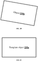
- An exemplary input image of an object 235b is as shown in FIG. 2B .
- the FIG. 2B shows a rectangular metal plate as the object 235b.
- the data extracting module 223 may extract the data from the input image.
- the data extracting module 223 selects the region of interest in the input image.
- the data extracting module 223 analyses contours corresponding to the region of interest using the one or more image processing algorithms at sub-pixel level to extract the data and stores as the extracted data 209.
- the extracted data 209 may include information related to at least one of edges and/or contours of the object corresponding to the region of interest in the input image.
- the comparison module 225 may compare the extracted data with the extracted template data.
- the comparison module 225 obtains the template data required for the comparison based on machine learning approach. By performing the machine learning approach, the mark file of one of the one or more template objects is created.
- the one of the one or more template objects selected for the comparison may be identical or similar to the object in the input image in terms of dimensions, shape, the content data to be marked and/or the like.
- the template data present in the selected mark file is extracted for the comparison.
- the comparison module 225 compares the extracted data of the object with the template data of the selected template object.
- the comparison module 225 determines transformation in position of the object with respect to the position of the selected template object.
- the transformation of the object determined by the comparison module 225 is stored as the transformation data 213.
- the transformation may include, but not limited to, a translation, a rotation and/or a skew.
- a translation e.g., a translation of (tx,ty)
- the transformation of the object with respect to translation x + tx, y + ty).
- the inverse applying module 227 may apply inverse of the transformation to the content data. Upon determining the transformation, the inverse applying module 227 determines the inverse of the transformation. The inverse of the transformation is applied to the content data and stored as the inverse transformation data 215. Based on the inverse of the transformation applied to the content data, a laser head of the laser marking device realigns, thereby marking the content data at the desired location on the surface of the object which is transformed.
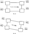
- the regions of interest selected in the one or more template images are corners (corner 235a-1 , 235a-2 , 235a-3 and 235a-4 ) of the template object 235a as shown in the FIG. 2D .
- template data corresponding to the regions of interest is extracted.
- the content data comprising vectors and content attributes corresponding to a content to be marked on the surface of the template object 235a is received by the transformation identification system 107.
- the content data and the template data are stored together to form a mark file.
- the mark file comprises a predefined format such as an XML format.
- the transformation identification system 107 is trained using the mark file to perform machine learning in real-time.
- the transformation identification system 107 receives the mark file for marking the content data on an exemplary object 235b as shown in the FIG. 2B .
- the transformation identification system 107 receives an input image of the object 235b to check if the object 235b is placed accurately.
- the regions of interest selected in the object 235b images are corners (corner 235b-1 , 235b-2 , 235b-3 and 235b-4 ) of the object 235b as shown in the FIG. 2E .
- Data corresponding to the regions of interest is extracted using the one or more image processing algorithms.
- the transformation identification system 107 obtains the template data apt for comparison with the extracted data by the machine learning approach.
- the extracted data of the object 235b is compared with the template data to determine transformation in the position of the object 235b with respect to the position of the template object 235a.
- the transformation determined provides measurement of translation, rotation and/or skew of the object 235b that occurred due to wrong placement of the object 235b.
- An inverse of the transformation determined is applied to vectors of the content data and the laser head of the laser marking device is realigned to the new vectors obtained by applying the inverse of the transformation.
- the content data comprising the new vectors is marked accordingly on the object 235b to mark the content data on the desired location using the laser as shown in the FIG. 2F .
- FIG. 3 shows a flowchart illustrating a method for marking content on a surface of an object using laser in accordance with some embodiments of the present disclosure.
- the method 300 includes one or more blocks illustrating a method for marking content on a surface of an object using laser.
- the method 300 may be described in the general context of computer executable instructions.
- computer executable instructions can include routines, programs, objects, components, data structures, procedures, modules, and functions, which perform functions or implement abstract data types.
- the order in which the method 300 is described is not intended to be construed as a limitation, and any number of the described method blocks can be combined in any order to implement the method. Additionally, individual blocks may be deleted from the methods without departing from the scope of the subject matter described herein. Furthermore, the method can be implemented in any suitable hardware, software, firmware, or combination thereof.
- the method 300 includes receiving, by a processor 109 of the transformation identification system 107 , an input image of an object from one or more image sources.
- the one or more image sources 103 may include, but not limited to, an image repository and an image capturing device such as a camera, a mobile, a tablet and the like.
- the method 300 includes extracting, by the processor 109 , data from the input image.
- the processor 109 analyses contours corresponding to a region of interest in the input image using one or more image processing algorithms to extract the data.
- the region of interest may be edges, contours, central region and the like.
- the method 300 includes, comparing, by the processor 109, the extracted data with extracted template data corresponding to regions of interest present in one or more template images of one of one or more template objects, such as a template object corresponding to the object to be marked.
- the template data is extracted based on machine learning performed on the one or more template images.
- the method 300 includes, determining, by the processor 109 , transformation in a position of the object with respect to position of the one of the one or more template objects, based on the comparison.
- the transformation may include, but not limited to, a translation, a rotation and/or a skew.
- the method 300 includes, applying, by the processor 109 , an inverse of the transformation to content data that may be marked on surface of the object at a desired location within the region of interest of the object.
- the inverse of the transformation is applied to the content data prior to marking the content data on the object.
- FIG. 4 is a block diagram of an exemplary computer system for implementing embodiments consistent with the present disclosure.
- FIG. 4 illustrates a block diagram of an exemplary computer system 400 for implementing embodiments consistent with the present invention.
- the computer system 400 can be transformation identification system 107 that is used for marking content on a surface of an object using laser.
- the computer system 400 may include a central processing unit (“CPU” or "processor") 402.
- the processor 402 may include at least one data processor for executing program components for executing user- or system-generated business processes.
- a user may include a person, a person using a device such as such as those included in this invention, or such a device itself.
- the processor 402 may include specialized processing units such as integrated system (bus) controllers, memory management control units, floating point units, graphics processing units, digital signal processing units, etc.
- the processor 402 may be disposed in communication with one or more input/output (I/O) devices ( 411 and 412 ) via I/O interface 401.
- the I/O interface 401 may employ communication protocols/methods such as, without limitation, audio, analog, digital, stereo, IEEE-1394, serial bus, Universal Serial Bus (USB), infrared, PS/2, BNC, coaxial, component, composite, Digital Visual Interface (DVI), high-definition multimedia interface (HDMI), Radio Frequency (RF) antennas, S-Video, Video Graphics Array (VGA), IEEE 802.n /b/g/n/x, Bluetooth, cellular (e.g., Code-Division Multiple Access (CDMA), High-Speed Packet Access (HSPA+), Global System For Mobile Communications (GSM), Long-Term Evolution (LTE), WiMax, or the like), etc.
- CDMA Code-Division Multiple Access
- HSPA+ High-Speed Packet Access
- GSM Global System For Mobile Communications
- LTE Long-
- computer system 400 may communicate with one or more I/O devices ( 411 and 412 ).
- the processor 402 may be disposed in communication with a communication network 409 via a network interface 403.
- the network interface 403 may communicate with the communication network 409.
- the network interface 403 may employ connection protocols including, without limitation, direct connect, Ethernet (e.g., twisted pair 10/100/1000 Base T), Transmission Control Protocol/Internet Protocol (TCP/IP), token ring, IEEE 802.11a/b/g/n/x, etc.
- the computer system 400 may communicate with one or more image sources 410 ( a,..,n ).
- the communication network 409 can be implemented as one of the different types of networks, such as intranet or Local Area Network (LAN) and such within the organization.
- LAN Local Area Network
- the communication network 409 may either be a dedicated network or a shared network, which represents an association of the different types of networks that use a variety of protocols, for example, Hypertext Transfer Protocol (HTTP), Transmission Control Protocol/Internet Protocol (TCP/IP), Wireless Application Protocol (WAP), etc., to communicate with each other. Further, the communication network 409 may include a variety of network devices, including routers, bridges, servers, computing devices, storage devices, etc.
- the one or more image sources 410 ( a,...,n ) may include, but not limited to, a an image repository and an image capturing device such as a camera, a mobile, a tablet etc.
- the processor 402 may be disposed in communication with a memory 405 (e.g., RAM, ROM, etc. not shown in Fig.4 ) via a storage interface 404.
- the storage interface 404 may connect to memory 405 including, without limitation, memory drives, removable disc drives, etc., employing connection protocols such as Serial Advanced Technology Attachment (SATA), Integrated Drive Electronics (IDE), IEEE-1394, Universal Serial Bus (USB), fibre channel, Small Computer Systems Interface (SCSI), etc.
- the memory drives may further include a drum, magnetic disc drive, magneto-optical drive, optical drive, Redundant Array of Independent Discs (RAID), solid-state memory devices, solid-state drives, etc.
- the memory 405 may store a collection of program or database components, including, without limitation, a user interface 406 , an operating system 407 , a web browser 408 , etc.
- the computer system 400 may store user/application data, such as the data, variables, records, etc. as described in this invention.
- databases may be implemented as fault-tolerant, relational, scalable, secure databases such as Oracle or Sybase.
- the operating system 407 may facilitate resource management and operation of the computer system 400.
- Examples of operating systems include, without limitation, Apple Macintosh OS X, UNIX, Unix-like system distributions (e.g., Berkeley Software Distribution (BSD), FreeBSD, NetBSD, OpenBSD, etc.), Linux distributions (e.g., Red Hat, Ubuntu, Kubuntu, etc.), International Business Machines (IBM) OS/2, Microsoft Windows (XP, Vista/7/8, etc.), Apple iOS, Google Android, Blackberry Operating System (OS), or the like.
- the User interface 406 may facilitate display, execution, interaction, manipulation, or operation of program components through textual or graphical facilities.
- GUIs may provide computer interaction interface elements on a display system operatively connected to the computer system 400 , such as cursors, icons, check boxes, menus, scrollers, windows, widgets, etc.
- Graphical User Interfaces may be employed, including, without limitation, Apple Macintosh operating systems' Aqua, IBM OS/2, Microsoft Windows (e.g., Aero, Metro, etc.), Unix X-Windows, web interface libraries (e.g., ActiveX, Java, Javascript, AJAX, HTML, Adobe Flash, etc.), or the like.
- the computer system 400 may implement the web browser 408 stored program components.
- the web browser 408 may be a hypertext viewing application, such as Microsoft Internet Explorer, Google Chrome, Mozilla Firefox, Apple Safari, etc. Secure web browsing may be provided using Secure Hypertext Transport Protocol (HTTPS) secure sockets layer (SSL), Transport Layer Security (TLS), etc. Web browsers may utilize facilities such as AJAX, DHTML, Adobe Flash, JavaScript, Java, Application Programming Interfaces (APIs), etc.
- the computer system 400 may implement a mail server stored program component.
- the mail server may be an Internet mail server such as Microsoft Exchange, or the like.
- the mail server may utilize facilities such as Active Server Pages (ASP), ActiveX, American National Standards Institute (ANSI) C++/C#, Microsoft .NET, CGI scripts, Java, JavaScript, PERL, PHP, Python, WebObjects, etc.
- the mail server may utilize communication protocols such as Internet Message Access Protocol (IMAP), Messaging Application Programming Interface (MAPI), Microsoft Exchange, Post Office Protocol (POP), Simple Mail Transfer Protocol (SMTP), or the like.
- the computer system 400 may implement a mail client stored program component.
- the mail client may be a mail viewing application, such as Apple Mail, Microsoft Entourage, Microsoft Outlook, Mozilla Thunderbird, etc.
- a computer-readable storage medium refers to any type of physical memory on which information or data readable by a processor may be stored.
- a computer-readable storage medium may store instructions for execution by one or more processors, including instructions for causing the processor(s) to perform steps or stages consistent with the embodiments described herein.
- the term "computer-readable medium” should be understood to include tangible items and exclude carrier waves and transient signals, i.e., non-transitory. Examples include Random Access Memory (RAM), Read-Only Memory (ROM), volatile memory, non-volatile memory, hard drives, Compact Disc (CD) ROMs, Digital Video Disc (DVDs), flash drives, disks, and any other known physical storage media.
- the present disclosure provides a method and a system for marking content on a surface of an object using laser.
- the present disclosure includes a machine learning approach for selecting regions of interest in input image and template images for analysis. This makes transformation indication system, described in the present disclosure, to be extremely flexible and enables it to focus only on the regions of interest.
- the present disclosure includes a method which stores only the data corresponding to the region of interest in the form of vectors and measurements in a file of a predefined format instead of storing the entire image. Further, this data file is stored along with content data to obtain a mark file of the predefined format. Therefore, the analysis may be performed in one laser marking machine to create the mark file and the same mark file could be used across various laser marking machines for marking the content data on a desired location on the surface of the object.
- the present disclosure provides a feature wherein the analysis is performed at a sub-pixel level accuracy. Therefore, transformation comprising translation, rotation and/or skew identified in the position of the object is accurate.
- the present disclosure provides a feature wherein the transformation identification system is capable of automatically determining the inverse of the transformation and applying to the content data for accurate marking of the content data.
Landscapes
- Engineering & Computer Science (AREA)
- Physics & Mathematics (AREA)
- General Physics & Mathematics (AREA)
- Theoretical Computer Science (AREA)
- Computer Vision & Pattern Recognition (AREA)
- Optics & Photonics (AREA)
- Ceramic Engineering (AREA)
- Quality & Reliability (AREA)
- Laser Beam Processing (AREA)
- Length Measuring Devices By Optical Means (AREA)
Abstract
Description
- The present subject matter relates generally to image processing, and more particularly, but not exclusively to a method and system for marking content on the surface of an object using laser.
- Laser marking is a production of human and/or machine-readable identification or information on an object such as metal plate, plastic, glass, and the like. Laser marking is generally performed by laser marking machines that are provided with content to be marked and the measurements related to the content. Though, the process of marking content using laser is automated, one or more errors occur due to inaccurate placement of the object. The inaccurate placement of the object may result in transformation such as translation, rotation, skew and the like. Due to the transformation of the object, on which the content is to be marked, the laser marking device may mark the content at an incorrect location instead of a desired location. The one or more errors occurring in marking of the content on the object may be minute but are evident in showcasing that original content and the desired location is not achieved. This leads to waste of resources and valuable time.
- Existing techniques disclose detection of flaws in a position of the object, on which the content is to be marked, prior to marking the content on the object, based on image processing. Upon detecting the flaws, a relative displacement in the position of the object is computed. However, the existing techniques compute only displacement associated with the position of the object. The position of the object however may undergo transformation such as rotation and skew along with displacement, which are not considered. Therefore, results of the existing techniques are not accurate, thereby not solving the problem of marking the content at the desired location even if the object is not positioned accurately.
- One or more shortcomings of the prior art may be overcome and additional advantages may be provided through the present disclosure. Additional features and advantages may be realized through the techniques of the present disclosure. Other embodiments and aspects of the disclosure are described in detail herein and are considered a part of the claimed disclosure.
- Disclosed herein is a method for marking content on a surface of an object using laser. The method comprises receiving, by a transformation identification system, an input image of the object from one or more image sources. Upon receiving the input image, the transformation identification system extracts data corresponding to a region of interest in the input image. Further, the transformation identification system compares the extracted data with extracted template data corresponding to regions of interest present in one or more template images of a template object of one or more template objects. The template data is extracted based on machine learning performed on the one or more template images. Furthermore, the transformation identification system determines transformation in position of the object with respect to a position of the template object, based on the comparison. Finally, the transformation identification system, applies an inverse of the transformation to content data that is to be marked at a desired location within the region of interest of the object. The inverse of the transformation is applied prior to marking the content data.
- Further, the present disclosure includes a transformation identification system for marking content on a surface of an object using laser. The transformation identification system comprises a processor and a memory communicatively coupled to the processor. The memory stores the processor-executable instructions, which, on execution, causes the processor to receive an input image of the object from one or more image sources. Upon receiving the input image, the processor extracts data corresponding to a region of interest in the input image. Further, the processor compares the extracted data with extracted template data corresponding to regions of interest present in one or more template images of a template object of one or more template objects. The template data is extracted based on machine learning performed on the one or more template images. Furthermore, the processor determines transformation in position of the object with respect to a position of the template object, based on the comparison. Finally, the processor applies an inverse of the transformation to content data that is to be marked at a desired location within the region of interest of the object. The inverse of the transformation is applied prior to marking the content data.
- A non-transitory computer readable medium including instructions stored thereon that when processed by at least one processor cause an transformation identification system to perform operations comprising receiving an input image of the object from one or more image sources. Further, the instructions cause the processor to extract data corresponding to a region of interest in the input image. Furthermore, the instructions cause the processor to compare the extracted data with extracted template data corresponding to regions of interest present in one or more template images of a template object of one or more template objects. The template data is extracted based on machine learning performed on the one or more template images. Further, the instructions cause the processor to determine transformation in a position of the object with respect to a position of the template object, based on the comparison. Finally, the instructions cause the processor to apply an inverse of the transformation to content data that is to be marked at a desired location within the region of interest of the object, wherein the inverse of the transformation is applied prior to marking the content data.
- The foregoing summary is illustrative only and is not intended to be in any way limiting. In addition to the illustrative aspects, embodiments, and features described above, further aspects, embodiments, and features will become apparent by reference to the drawings and the following detailed description.
- The accompanying drawings, which are incorporated in and constitute a part of this disclosure, illustrate exemplary embodiments and, together with the description, serve to explain the disclosed principles. In the figures, the left-most digit(s) of a reference number identifies the figure in which the reference number first appears. The same numbers are used throughout the figures to reference like features and components. Some embodiments of system and/or methods in accordance with embodiments of the present subject matter are now described, by way of example only, and with reference to the accompanying figures, in which:
-
FIG. 1 shows an exemplary architecture illustrating process for marking content on a surface of an object using laser in accordance with some embodiments of the present disclosure; -
FIG. 2A shows a detailed block diagram of a transformation identification system for marking content on a surface of an object using laser in accordance with some embodiments of the present disclosure; -
FIGs. 2B, 2C ,2D , and2F show exemplary images illustrating an exemplary scenario for marking content on a surface of an object using laser with some embodiments of the present disclosure; -
FIG. 3 shows a flowchart illustrating a method for marking content on a surface of an object using laser in accordance with some embodiments of the present disclosure; and -
FIG. 4 is a block diagram of an exemplary computer system for implementing embodiments consistent with the present disclosure. - It should be appreciated by those skilled in the art that any block diagrams herein represent conceptual views of illustrative systems embodying the principles of the present subject matter. Similarly, it will be appreciated that any flow charts, flow diagrams, state transition diagrams, pseudo code, and the like represent various processes which may be substantially represented in computer readable medium and executed by a computer or processor, whether or not such computer or processor is explicitly shown.
- In the present document, the word "exemplary" is used herein to mean "serving as an example, instance, or illustration." Any embodiment or implementation of the present subject matter described herein as "exemplary" is not necessarily to be construed as preferred or advantageous over other embodiments.
- While the disclosure is susceptible to various modifications and alternative forms, specific embodiment thereof has been shown by way of example in the drawings and will be described in detail below. It should be understood, however that it is not intended to limit the disclosure to the forms disclosed, but on the contrary, the disclosure is to cover all modifications, equivalents, and alternative falling within the scope of the disclosure.
- The terms "comprises", "comprising", "includes" or any other variations thereof, are intended to cover a non-exclusive inclusion, such that a setup, device or method, that includes a list of components or steps, and does not include only those components or steps but may include other components or steps not expressly listed or inherent to such setup or device or method. In other words, one or more elements in a system or apparatus proceeded by "comprises... a" does not, without more constraints, preclude the existence of other elements or additional elements in the system or method.
- Disclosed herein is a method and system for marking content on the surface of an object using laser. The transformation identification system receives an input image of the object from one or more image sources. Upon receiving the input image, the transformation identification system extracts data corresponding to a region of interest in the input image based on machine learning approach. Further, the transformation identification system compares the extracted data with extracted template data corresponding to regions of interest present in one or more template images of one of one or more template objects. The template data is extracted based on machine learning performed on the one or more template images. The extracted data and the template data comprise information related to at least one of edges and/or contours of the object and the one or more template objects, respectively. The present disclosure stores only the data corresponding to the region of interest in the form of vectors and measurements in a mark file of a predefined format instead of storing the entire image. Furthermore, the transformation identification system determines transformation in a position of the object with respect to the position of one of the one or more template objects, based on the comparison. As an example, the transformation may include, but not limited to, a translation, a rotation and/or a skew. Finally, the transformation identification system, applies an inverse of the transformation (e.g., if the transformation includes a rotation, a reverse rotation is applied) to content data that is to be marked at a desired location within the region of interest of the object. The inverse of the transformation is applied prior to marking the content data. The present disclosure is capable of performing an intelligent machine learning approach to select the regions of interest in input image and template images for analysis. This allows the transformation indication system to be extremely flexible and focus only on the regions of interest. Further, the transformation indication system enables content marking on a desired location even if the object is moved/rotated.
- In the following detailed description of the embodiments of the disclosure, reference is made to the accompanying drawings that form a part hereof, and in which are shown by way of illustration specific embodiments in which the disclosure may be practiced. These embodiments are described in sufficient detail to enable those skilled in the art to practice the disclosure, and it is to be understood that other embodiments may be utilized and that changes may be made without departing from the scope of the present disclosure. The following description is, therefore, not to be taken in a limiting sense.
-
FIG. 1 shows an exemplary architecture for marking content on a surface of an object using laser in accordance with some embodiments of the present disclosure. - The
architecture 100 includes one or more image sources,image source 1 1031 to image source n 103n (collectively referred to as one or more image sources 103) and atransformation identification system 107. As an example, the one ormore image sources 103 may include, but are not limited to, an image repository and an image capturing device such as a camera, a mobile, a tablet and the like. As an example, the image capturing device may be at least one of a monochrome image capturing device and a color image capturing device. Thetransformation identification system 107 interacts with the one ormore image sources 103 via a communication network (not shown in theFIG.1 ). The communication network may be at least one of a wired communication network and a wireless communication network. - The
transformation identification system 107 includes aprocessor 109, an input/output (I/O)interface 111 and amemory 113. The I/O interface 111 receives an input image of an object from the one or more image sources 103. As an example, the object may include, but not limited to, a metallic object, such as an aluminum plate, iron plate and the like and/or a non-metallic object, such as a plastic plate, a wooden plate, a glass and the like. Theprocessor 109 extracts data corresponding to a region of interest in the input image. As an example, the region of interest may be edges of the input image, contours of the input image, central region of the input image and the like. Upon extracting the data, theprocessor 109 compares the extracted data with extracted template data at a sub-pixel level. The extracted template data corresponds to regions of interest present in one or more template images of one of one or more template objects, such as a template object corresponding to the object to be marked, for example in shape, form, size, and/or other properties. As an example, the extracted data and the template data may include, but not limited to, information related to at least one of edges and/or contours of the object and the one or more template objects respectively. In an embodiment, the one or more template objects are objects placed at accurate positions for marking content data prior to actual marking of the content data. In an embodiment, the content data comprises vectors and content attributes corresponding to a content to be marked on a surface of the one or more template objects. Further, theprocessor 109 may extract the template data required for comparison based on machine learning performed on the one or more template images of one of the one or more template objects using one or more image processing algorithms. As an example, the one or more image processing algorithms may be based on, but not limited to, a Matrox Imaging Library (MIL) blob analysis, an image calibration operation, an image edge finder algorithm, a geometric model finder algorithm measurement, metrology, and/or one or more pattern matching operations. Further to the comparison, theprocessor 109 may determine transformation in position of the object with respect to position of the one of the one or more template objects. As an example, the transformation may include, but not limited to, a translation, a rotation and/or a skew. Upon determining the transformation, theprocessor 109 may apply an inverse of the transformation to the content data prior to marking the content data. The inverse of the transformation may allow marking the content data at a desired location within the region of interest of the object, although the transformation in the position of the object is present. Therefore, to mark the content data at the desired location, theprocessor 109 realigns a laser head of a laser marking device associated with thetransformation identification system 107 based on the inverse of the transformation applied to the content data by theprocessor 109. -
FIG. 2A shows a detailed block diagram of the transformation identification system for marking content on a surface of an object using laser in accordance with some embodiments of the present disclosure. - In some implementations, the
transformation identification system 107 includesdata 203 andmodules 205. As an example, thedata 203 is stored in thememory 113 configured in thetransformation identification system 107 as shown in theFIG. 2A . In one embodiment, thedata 203 includes aninput image data 207, an extracteddata 209, a mark file data 211, atransformation data 213, aninverse transformation data 215 andother data 219. In the illustratedFIG. 2A ,modules 205 are described herein in detail. - In some embodiments, the
data 203 may be stored in thememory 113 in form of various data structures. Additionally, thedata 203 can be organized using data models, such as relational or hierarchical data models. Theother data 219 may store data, including temporary data and temporary files, generated by themodules 205 for performing the various functions of thetransformation identification system 107. - In some embodiments, the data stored in the
memory 113 is processed by themodules 205 of thetransformation identification system 107. Themodules 205 may be stored within thememory 113. In an example, themodules 205 communicatively coupled to aprocessor 109 configured in thetransformation identification system 107, may also be present outside thememory 113 as shown inFIG. 2A and implemented as hardware. As used herein, the term modules refers to an application specific integrated circuit (ASIC), an electronic circuit, a processor (shared, dedicated, or group) and memory that execute one or more software or firmware programs, a combinational logic circuit, and/or other suitable components that provide the described functionality. - In an embodiment, the
modules 205 may include, for example, a markfile creating module 220, a receivingmodule 221, adata extracting module 223, acomparison module 225, aninverse applying module 227 andother modules 233. Theother modules 233 may be used to perform various miscellaneous functionalities of thetransformation identification system 107. It will be appreciated that suchaforementioned modules 205 may be represented as a single module or a combination of different modules. - In some embodiments, the mark
file creating module 220 may create a mark file for each of the one or more template objects. Each mark file includes the template data corresponding to one of the one or more template objects and a content data to be marked on the surface of one of the one or more template objects. In an embodiment, the template data comprises information related to at least one of edges and/or contours of the one or more template objects corresponding to regions of interest in one or more template images corresponding to the one or more template objects. As an example, the region of interest may be edges, contours, central region and the like. Further, the content data comprises vectors and content attributes corresponding to a content to be marked on the surface of the one or more template objects. As an example, the content attributes may include pixel intensity, color and the like. In some embodiments, the mark file is created to train thetransformation identification system 107 with extreme accuracy for performing machine learning. The mark file having a predefined format for each of the one or more template objects may be stored as the mark file data 211. As an example, the predefined format may be an XML format and the like. - The mark
file creating module 220 may create the mark file by initially receiving the one or more template images of the one or more template objects. The one or more template images are received from one or more image sources 103. The one or more template images are of the one or more template objects placed with extreme accuracy with respect to measurements. The placement of the one or more template objects ensures that correct edges of the one or more template objects are captured in the one or more template images. Further, the markfile creating module 220 receives the content data for each of the one or more template objects. In an embodiment, the content data may be at least one of pre-stored in thememory 113 or dynamically created. The content data received by the markfile creating module 220 is pre-inspected. - Upon receiving the one or more template images and the content data, the mark
file creating module 220 may select the regions of interest in the one or more template images. Further, thedata extracting module 223 may extract the template data corresponding to the regions of interest based on analysis of contours of each of the one or more template objects present in each of the one or more template images. In some embodiments, the analysis of contours of each of the one or more template objects may be performed using one or more image processing algorithms. As an example, the one or more image processing algorithms may be based on, but not limited to, Matrox Imaging Library (MIL) blob analysis, an image calibration operation, an image edge finder algorithm, a geometric model finder algorithm measurement, metrology, and/or one or more pattern matching operations. The extracted template data may be stored in the form of vectors. Further, the markfile creating module 220 creates the mark file having the predefined format by storing the template data along with the content data in the mark file. The mark file thus created may be transmitted to a laser marking device associated with thetransformation identification system 107 for marking the content data on a surface of an object using laser. In a non-limiting embodiment, the content data may be marked on the object using a technology other than laser. Therefore, the analysis may be performed with respect to one laser marking machine to create the mark file and the same mark file could be used across similar laser marking machines for marking the content data on a desired location on the surface of the object. - In some embodiments, the receiving
module 221 receives an input image of the object from the one or more image sources 103. The input image received may be stored in theinput image data 207. As an example, the object may include, but not limited to, a metallic object such as an aluminum plate, iron plate and the like and/or a non-metallic object such as a plastic plate, a wooden plate, a glass and the like. An exemplary input image of anobject 235b is as shown inFIG. 2B . TheFIG. 2B shows a rectangular metal plate as theobject 235b. - In some embodiments, the
data extracting module 223 may extract the data from the input image. Thedata extracting module 223 selects the region of interest in the input image. Upon selecting the region of interest, thedata extracting module 223 analyses contours corresponding to the region of interest using the one or more image processing algorithms at sub-pixel level to extract the data and stores as the extracteddata 209. In an embodiment, the extracteddata 209 may include information related to at least one of edges and/or contours of the object corresponding to the region of interest in the input image. - In some embodiments, the
comparison module 225 may compare the extracted data with the extracted template data. Thecomparison module 225 obtains the template data required for the comparison based on machine learning approach. By performing the machine learning approach, the mark file of one of the one or more template objects is created. In an embodiment, the one of the one or more template objects selected for the comparison may be identical or similar to the object in the input image in terms of dimensions, shape, the content data to be marked and/or the like. Upon selecting the mark file associated with one of the one or more template objects, the template data present in the selected mark file is extracted for the comparison. Upon obtaining the template data, thecomparison module 225 compares the extracted data of the object with the template data of the selected template object. Based on the comparison, thecomparison module 225 determines transformation in position of the object with respect to the position of the selected template object. The transformation of the object determined by thecomparison module 225 is stored as thetransformation data 213. As an example, the transformation may include, but not limited to, a translation, a rotation and/or a skew. As an example, consider coordinates of a corner of the object is (x,y). If the object undergoes a translation of (tx,ty), then the transformation of the object with respect to translation is (x + tx, y + ty). - In some embodiments, the
inverse applying module 227 may apply inverse of the transformation to the content data. Upon determining the transformation, theinverse applying module 227 determines the inverse of the transformation. The inverse of the transformation is applied to the content data and stored as theinverse transformation data 215. Based on the inverse of the transformation applied to the content data, a laser head of the laser marking device realigns, thereby marking the content data at the desired location on the surface of the object which is transformed. - Henceforth, the process of marking the content data on the surface of the object using the laser is explained with the help of one or more examples for better understanding of the present disclosure. However, the one or more examples should not be considered as limitation of the present disclosure.
- Consider an
exemplary template object 235a placed with extreme accuracy as shown in theFIG. 2C . Further, consider one or more template images of thetemplate object 235a are received from an image capturing device such as a camera. In an embodiment, the regions of interest selected in the one or more template images are corners (corner 235a-1, 235a-2, 235a-3 and 235a-4) of thetemplate object 235a as shown in theFIG. 2D . Further, by using the one or more image processing algorithms, template data corresponding to the regions of interest is extracted. Furthermore, the content data comprising vectors and content attributes corresponding to a content to be marked on the surface of thetemplate object 235a is received by thetransformation identification system 107. The content data and the template data are stored together to form a mark file. The mark file comprises a predefined format such as an XML format. Thetransformation identification system 107 is trained using the mark file to perform machine learning in real-time. - Consider the laser marking device associated with the
transformation identification system 107 receives the mark file for marking the content data on anexemplary object 235b as shown in theFIG. 2B . According to the content data in the mark file, consider that the desired location where the content data should be marked is exactly at the center of theobject 235b. Therefore, prior to marking the content data, thetransformation identification system 107 receives an input image of theobject 235b to check if theobject 235b is placed accurately. The regions of interest selected in theobject 235b images are corners (corner 235b-1, 235b-2, 235b-3 and 235b-4) of theobject 235b as shown in theFIG. 2E . Data corresponding to the regions of interest is extracted using the one or more image processing algorithms. Thetransformation identification system 107 obtains the template data apt for comparison with the extracted data by the machine learning approach. The extracted data of theobject 235b is compared with the template data to determine transformation in the position of theobject 235b with respect to the position of thetemplate object 235a. The transformation determined provides measurement of translation, rotation and/or skew of theobject 235b that occurred due to wrong placement of theobject 235b. An inverse of the transformation determined is applied to vectors of the content data and the laser head of the laser marking device is realigned to the new vectors obtained by applying the inverse of the transformation. The content data comprising the new vectors is marked accordingly on theobject 235b to mark the content data on the desired location using the laser as shown in theFIG. 2F . -
FIG. 3 shows a flowchart illustrating a method for marking content on a surface of an object using laser in accordance with some embodiments of the present disclosure. - As illustrated in
FIG. 3 , themethod 300 includes one or more blocks illustrating a method for marking content on a surface of an object using laser. Themethod 300 may be described in the general context of computer executable instructions. Generally, computer executable instructions can include routines, programs, objects, components, data structures, procedures, modules, and functions, which perform functions or implement abstract data types. - The order in which the
method 300 is described is not intended to be construed as a limitation, and any number of the described method blocks can be combined in any order to implement the method. Additionally, individual blocks may be deleted from the methods without departing from the scope of the subject matter described herein. Furthermore, the method can be implemented in any suitable hardware, software, firmware, or combination thereof. - At
block 301, themethod 300 includes receiving, by aprocessor 109 of thetransformation identification system 107, an input image of an object from one or more image sources. As an example, the one ormore image sources 103 may include, but not limited to, an image repository and an image capturing device such as a camera, a mobile, a tablet and the like. - At
block 303, themethod 300 includes extracting, by theprocessor 109, data from the input image. Theprocessor 109 analyses contours corresponding to a region of interest in the input image using one or more image processing algorithms to extract the data. As an example, the region of interest may be edges, contours, central region and the like. - At
block 305, themethod 300 includes, comparing, by theprocessor 109, the extracted data with extracted template data corresponding to regions of interest present in one or more template images of one of one or more template objects, such as a template object corresponding to the object to be marked. In an embodiment, the template data is extracted based on machine learning performed on the one or more template images. - At
block 307, themethod 300 includes, determining, by theprocessor 109, transformation in a position of the object with respect to position of the one of the one or more template objects, based on the comparison. As an example, the transformation may include, but not limited to, a translation, a rotation and/or a skew. - At
block 309, themethod 300 includes, applying, by theprocessor 109, an inverse of the transformation to content data that may be marked on surface of the object at a desired location within the region of interest of the object. In an embodiment, the inverse of the transformation is applied to the content data prior to marking the content data on the object. -
FIG. 4 is a block diagram of an exemplary computer system for implementing embodiments consistent with the present disclosure. - In an embodiment,
FIG. 4 illustrates a block diagram of anexemplary computer system 400 for implementing embodiments consistent with the present invention. In an embodiment, thecomputer system 400 can betransformation identification system 107 that is used for marking content on a surface of an object using laser. Thecomputer system 400 may include a central processing unit ("CPU" or "processor") 402. Theprocessor 402 may include at least one data processor for executing program components for executing user- or system-generated business processes. A user may include a person, a person using a device such as such as those included in this invention, or such a device itself. Theprocessor 402 may include specialized processing units such as integrated system (bus) controllers, memory management control units, floating point units, graphics processing units, digital signal processing units, etc. - The
processor 402 may be disposed in communication with one or more input/output (I/O) devices (411 and 412) via I/O interface 401. The I/O interface 401 may employ communication protocols/methods such as, without limitation, audio, analog, digital, stereo, IEEE-1394, serial bus, Universal Serial Bus (USB), infrared, PS/2, BNC, coaxial, component, composite, Digital Visual Interface (DVI), high-definition multimedia interface (HDMI), Radio Frequency (RF) antennas, S-Video, Video Graphics Array (VGA), IEEE 802.n /b/g/n/x, Bluetooth, cellular (e.g., Code-Division Multiple Access (CDMA), High-Speed Packet Access (HSPA+), Global System For Mobile Communications (GSM), Long-Term Evolution (LTE), WiMax, or the like), etc. - Using the I/
O interface 401,computer system 400 may communicate with one or more I/O devices (411 and 412). - In some embodiments, the
processor 402 may be disposed in communication with acommunication network 409 via anetwork interface 403. Thenetwork interface 403 may communicate with thecommunication network 409. Thenetwork interface 403 may employ connection protocols including, without limitation, direct connect, Ethernet (e.g., twisted pair 10/100/1000 Base T), Transmission Control Protocol/Internet Protocol (TCP/IP), token ring, IEEE 802.11a/b/g/n/x, etc. Using thenetwork interface 403 and thecommunication network 409, thecomputer system 400 may communicate with one or more image sources 410 (a,..,n). Thecommunication network 409 can be implemented as one of the different types of networks, such as intranet or Local Area Network (LAN) and such within the organization. Thecommunication network 409 may either be a dedicated network or a shared network, which represents an association of the different types of networks that use a variety of protocols, for example, Hypertext Transfer Protocol (HTTP), Transmission Control Protocol/Internet Protocol (TCP/IP), Wireless Application Protocol (WAP), etc., to communicate with each other. Further, thecommunication network 409 may include a variety of network devices, including routers, bridges, servers, computing devices, storage devices, etc. The one or more image sources 410 (a,...,n) may include, but not limited to, a an image repository and an image capturing device such as a camera, a mobile, a tablet etc. In some embodiments, theprocessor 402 may be disposed in communication with a memory 405 (e.g., RAM, ROM, etc. not shown inFig.4 ) via astorage interface 404. Thestorage interface 404 may connect tomemory 405 including, without limitation, memory drives, removable disc drives, etc., employing connection protocols such as Serial Advanced Technology Attachment (SATA), Integrated Drive Electronics (IDE), IEEE-1394, Universal Serial Bus (USB), fibre channel, Small Computer Systems Interface (SCSI), etc. The memory drives may further include a drum, magnetic disc drive, magneto-optical drive, optical drive, Redundant Array of Independent Discs (RAID), solid-state memory devices, solid-state drives, etc. - The
memory 405 may store a collection of program or database components, including, without limitation, a user interface 406, anoperating system 407, aweb browser 408, etc. In some embodiments, thecomputer system 400 may store user/application data, such as the data, variables, records, etc. as described in this invention. Such databases may be implemented as fault-tolerant, relational, scalable, secure databases such as Oracle or Sybase. - The
operating system 407 may facilitate resource management and operation of thecomputer system 400. Examples of operating systems include, without limitation, Apple Macintosh OS X, UNIX, Unix-like system distributions (e.g., Berkeley Software Distribution (BSD), FreeBSD, NetBSD, OpenBSD, etc.), Linux distributions (e.g., Red Hat, Ubuntu, Kubuntu, etc.), International Business Machines (IBM) OS/2, Microsoft Windows (XP, Vista/7/8, etc.), Apple iOS, Google Android, Blackberry Operating System (OS), or the like. The User interface 406 may facilitate display, execution, interaction, manipulation, or operation of program components through textual or graphical facilities. For example, user interfaces may provide computer interaction interface elements on a display system operatively connected to thecomputer system 400, such as cursors, icons, check boxes, menus, scrollers, windows, widgets, etc. Graphical User Interfaces (GUIs) may be employed, including, without limitation, Apple Macintosh operating systems' Aqua, IBM OS/2, Microsoft Windows (e.g., Aero, Metro, etc.), Unix X-Windows, web interface libraries (e.g., ActiveX, Java, Javascript, AJAX, HTML, Adobe Flash, etc.), or the like. - In some embodiments, the
computer system 400 may implement theweb browser 408 stored program components. Theweb browser 408 may be a hypertext viewing application, such as Microsoft Internet Explorer, Google Chrome, Mozilla Firefox, Apple Safari, etc. Secure web browsing may be provided using Secure Hypertext Transport Protocol (HTTPS) secure sockets layer (SSL), Transport Layer Security (TLS), etc. Web browsers may utilize facilities such as AJAX, DHTML, Adobe Flash, JavaScript, Java, Application Programming Interfaces (APIs), etc. In some embodiments, thecomputer system 400 may implement a mail server stored program component. The mail server may be an Internet mail server such as Microsoft Exchange, or the like. The mail server may utilize facilities such as Active Server Pages (ASP), ActiveX, American National Standards Institute (ANSI) C++/C#, Microsoft .NET, CGI scripts, Java, JavaScript, PERL, PHP, Python, WebObjects, etc. The mail server may utilize communication protocols such as Internet Message Access Protocol (IMAP), Messaging Application Programming Interface (MAPI), Microsoft Exchange, Post Office Protocol (POP), Simple Mail Transfer Protocol (SMTP), or the like. In some embodiments, thecomputer system 400 may implement a mail client stored program component. The mail client may be a mail viewing application, such as Apple Mail, Microsoft Entourage, Microsoft Outlook, Mozilla Thunderbird, etc. - Furthermore, one or more computer-readable storage media may be utilized in implementing embodiments consistent with the present invention. A computer-readable storage medium refers to any type of physical memory on which information or data readable by a processor may be stored. Thus, a computer-readable storage medium may store instructions for execution by one or more processors, including instructions for causing the processor(s) to perform steps or stages consistent with the embodiments described herein. The term "computer-readable medium" should be understood to include tangible items and exclude carrier waves and transient signals, i.e., non-transitory. Examples include Random Access Memory (RAM), Read-Only Memory (ROM), volatile memory, non-volatile memory, hard drives, Compact Disc (CD) ROMs, Digital Video Disc (DVDs), flash drives, disks, and any other known physical storage media.
- Advantages of the embodiment of the present disclosure are illustrated herein.
- In an embodiment, the present disclosure provides a method and a system for marking content on a surface of an object using laser.
- The present disclosure includes a machine learning approach for selecting regions of interest in input image and template images for analysis. This makes transformation indication system, described in the present disclosure, to be extremely flexible and enables it to focus only on the regions of interest.
- The present disclosure includes a method which stores only the data corresponding to the region of interest in the form of vectors and measurements in a file of a predefined format instead of storing the entire image. Further, this data file is stored along with content data to obtain a mark file of the predefined format. Therefore, the analysis may be performed in one laser marking machine to create the mark file and the same mark file could be used across various laser marking machines for marking the content data on a desired location on the surface of the object.
- The present disclosure provides a feature wherein the analysis is performed at a sub-pixel level accuracy. Therefore, transformation comprising translation, rotation and/or skew identified in the position of the object is accurate.
- The present disclosure provides a feature wherein the transformation identification system is capable of automatically determining the inverse of the transformation and applying to the content data for accurate marking of the content data.
- A description of an embodiment with several components in communication with each other does not imply that all such components are required. On the contrary a variety of optional components are described to illustrate the wide variety of possible embodiments of the invention.
- When a single device or article is described herein, it will be apparent that more than one device/article (whether or not they cooperate) may be used in place of a single device/article. Similarly, where more than one device or article is described herein (whether or not they cooperate), it will be apparent that a single device/article may be used in place of the more than one device or article or a different number of devices/articles may be used instead of the shown number of devices or programs. The functionality and/or the features of a device may be alternatively embodied by one or more other devices which are not explicitly described as having such functionality/features. Thus, other embodiments of the invention need not include the device itself.
- The specification has described a method and a system for marking content on a surface of an object using laser. The illustrated steps are set out to explain the exemplary embodiments shown, and it should be anticipated that on-going technological development will change the manner in which particular functions are performed. These examples are presented herein for purposes of illustration, and not limitation. Further, the boundaries of the functional building blocks have been arbitrarily defined herein for the convenience of the description. Alternative boundaries can be defined so long as the specified functions and relationships thereof are appropriately performed. Alternatives (including equivalents, extensions, variations, deviations, etc., of those described herein) will be apparent to persons skilled in the relevant art(s) based on the teachings contained herein. Such alternatives fall within the scope of the disclosed embodiments. Also, the words "comprising," "having," "containing," and "including," and other similar forms are intended to be equivalent in meaning and be open ended in that an item or items following any one of these words is not meant to be an exhaustive listing of such item or items, or meant to be limited to only the listed item or items. It must also be noted that as used herein and in the appended claims, the singular forms "a," "an," and "the" include plural references unless the context clearly dictates otherwise.
- Finally, the language used in the specification has been principally selected for readability and instructional purposes, and it may not have been selected to delineate or circumscribe the inventive subject matter. It is therefore intended that the scope of the invention be limited not by this detailed description, but rather by any claims that issue on an application based here on. Accordingly, the embodiments of the present invention are intended to be illustrative, but not limiting, of the scope of the invention, which is set forth in the following claims.
Claims (10)
- A method for marking content on a surface of an object using a laser, the method comprising:receiving, by a transformation identification system (107), an input image of the object from one or more image sources (103);extracting, by the transformation identification system (107), data corresponding to a region of interest in the input image;comparing, by the transformation identification system (107), the extracted data with extracted template data corresponding to regions of interest present in one or more template images of a template object of one or more template objects, wherein the template data is extracted based on machine learning performed on the one or more template images;determining, by the transformation identification system (107), a transformation in a position of the object with respect to a position of the template object, based on the comparison; andapplying, by the transformation identification system (107), an inverse of the transformation to content data that is to be marked at a desired location within the region of interest of the object, wherein the inverse of the transformation is applied prior to marking the content data.
- The method as claimed in claim 1, wherein the transformation comprises at least one of translation, rotation, and skew.
- The method as claimed in claim 1 or claim 2, further comprising realigning, by the transformation identification system (107), a laser head of a laser marking device associated with the transformation identification system (107) based on the inverse of the transformation for marking the content data at the desired location.
- The method as claimed in any of the preceding claims, wherein the template data is obtained by:receiving, by the transformation identification system (107), the one or more template images of the one or more template objects along with the content data, wherein the content data comprises vectors and content attributes corresponding to a content to be marked on a surface of the template object;extracting, by the transformation identification system (107), the template data corresponding to the regions of interest, based on analysis of contours of each of the one or more template objects present in each of the one or more template images using one or more image processing algorithms; andstoring, by the transformation identification system (107), the template data along with the content data in a mark file having a predefined format.
- The method as claimed in claim 4, wherein the mark file is transmitted to a laser marking device associated with the transformation identification system (107) for marking the content data on the object.
- The method as claimed in claim 4 or claim 5, wherein the image processing algorithms are based on at least one of a Matrox Imaging Library (MIL) blob analysis, an image calibration operation, an image edge finder algorithm, a geometric model finder algorithm measurement, metrology, and/or one or more pattern matching operations.
- The method as claimed in any of the preceding claims, wherein the data and the template data comprise information related to at least one of edges and/or contours of the object and the one or more template objects, respectively.
- The method as claimed in any of the preceding claims, wherein the comparison is performed by the transformation identification system (107) at a sub-pixel level.
- A transformation identification system (107) for marking content on a surface of an object using a laser, the transformation identification system (107) comprising:a processor (109); anda memory (113) communicatively coupled to the processor (109), wherein the memory (113) stores the processor-executable instructions, which, on execution, cause the processor (109) to perform the method as claimed in any of the preceding claims..
- A non-transitory computer readable medium including instructions stored thereon that when processed by at least one processor (109) causes a transformation identification system (107) to perform operations of the method as claimed in any of claims 1 to 8.
Applications Claiming Priority (1)
| Application Number | Priority Date | Filing Date | Title |
|---|---|---|---|
| IN201741007702 | 2017-03-04 |
Publications (1)
| Publication Number | Publication Date |
|---|---|
| EP3370203A1 true EP3370203A1 (en) | 2018-09-05 |
Family
ID=59772360
Family Applications (1)
| Application Number | Title | Priority Date | Filing Date |
|---|---|---|---|
| EP17186067.9A Withdrawn EP3370203A1 (en) | 2017-03-04 | 2017-08-11 | Method and system for marking content on the surface of an object using laser |
Country Status (2)
| Country | Link |
|---|---|
| US (1) | US10410340B2 (en) |
| EP (1) | EP3370203A1 (en) |
Cited By (2)
| Publication number | Priority date | Publication date | Assignee | Title |
|---|---|---|---|---|
| CN113134683A (en) * | 2021-05-13 | 2021-07-20 | 兰州理工大学 | Laser marking method and device based on machine learning |
| CN114136893A (en) * | 2021-11-29 | 2022-03-04 | 国能铁路装备有限责任公司 | Wheel set sign plate recognition device and method |
Families Citing this family (1)
| Publication number | Priority date | Publication date | Assignee | Title |
|---|---|---|---|---|
| KR101637716B1 (en) * | 2014-11-03 | 2016-07-07 | 현대자동차주식회사 | Apparatus and method for recognizing position of obstacle in vehicle |
Citations (3)
| Publication number | Priority date | Publication date | Assignee | Title |
|---|---|---|---|---|
| WO2009117700A2 (en) * | 2008-03-21 | 2009-09-24 | Foba Technology + Services Gmbh | Multi model registration (mmr) for a galvanometer and laser system |
| US20140375794A1 (en) * | 2013-06-25 | 2014-12-25 | The Boeing Company | Apparatuses and methods for accurate structure marking and marking-assisted structure locating |
| CN105424008A (en) * | 2015-12-01 | 2016-03-23 | 广东顺德华焯机械科技有限公司 | Laser marking galvanometer scanning system based on machine vision |
Family Cites Families (2)
| Publication number | Priority date | Publication date | Assignee | Title |
|---|---|---|---|---|
| US4918611A (en) * | 1988-07-21 | 1990-04-17 | Industrial Technology Research Institute | Method and apparatus for controlling laser cutting by image processing |
| US8103085B1 (en) | 2007-09-25 | 2012-01-24 | Cognex Corporation | System and method for detecting flaws in objects using machine vision |
-
2017
- 2017-03-20 US US15/463,880 patent/US10410340B2/en active Active
- 2017-08-11 EP EP17186067.9A patent/EP3370203A1/en not_active Withdrawn
Patent Citations (3)
| Publication number | Priority date | Publication date | Assignee | Title |
|---|---|---|---|---|
| WO2009117700A2 (en) * | 2008-03-21 | 2009-09-24 | Foba Technology + Services Gmbh | Multi model registration (mmr) for a galvanometer and laser system |
| US20140375794A1 (en) * | 2013-06-25 | 2014-12-25 | The Boeing Company | Apparatuses and methods for accurate structure marking and marking-assisted structure locating |
| CN105424008A (en) * | 2015-12-01 | 2016-03-23 | 广东顺德华焯机械科技有限公司 | Laser marking galvanometer scanning system based on machine vision |
Cited By (2)
| Publication number | Priority date | Publication date | Assignee | Title |
|---|---|---|---|---|
| CN113134683A (en) * | 2021-05-13 | 2021-07-20 | 兰州理工大学 | Laser marking method and device based on machine learning |
| CN114136893A (en) * | 2021-11-29 | 2022-03-04 | 国能铁路装备有限责任公司 | Wheel set sign plate recognition device and method |
Also Published As
| Publication number | Publication date |
|---|---|
| US10410340B2 (en) | 2019-09-10 |
| US20180253835A1 (en) | 2018-09-06 |
Similar Documents
| Publication | Publication Date | Title |
|---|---|---|
| US9792664B2 (en) | System and method for mapping object coordinates from a video to real world coordinates using perspective transformation | |
| US10678848B2 (en) | Method and a system for recognition of data in one or more images | |
| US10902638B2 (en) | Method and system for detecting pose of a subject in real-time | |
| US20180217722A1 (en) | Method and System for Establishing a Relationship Between a Plurality of User Interface Elements | |
| US20160259991A1 (en) | Method and image processing apparatus for performing optical character recognition (ocr) of an article | |
| US10241898B2 (en) | Method and system for enabling self-maintainable test automation | |
| US20170103558A1 (en) | Method and system for generating panoramic images with real-time annotations | |
| US10769472B2 (en) | Method and system counting plurality of objects placed in a region | |
| EP3051495B1 (en) | Systems and methods for mapping object coordinates from a video frame view to real world coordinates | |
| EP3200124B1 (en) | Method and system for processing an image extracted from a document | |
| US10410340B2 (en) | Method and system for marking content on the surface of an object using laser | |
| US20200264620A1 (en) | Method and system for determining drivable road regions for safe navigation of an autonomous vehicle | |
| US10297056B2 (en) | Method and system for remotely annotating an object in real-time | |
| WO2020079704A1 (en) | Method and system for performing semantic segmentation of plurality of entities in an image | |
| US10621453B2 (en) | Method and system for determining relationship among text segments in signboards for navigating autonomous vehicles | |
| US10178358B2 (en) | Method for surveillance of an area of interest and a surveillance device thereof | |
| EP3355240B1 (en) | A method and a system for generating a multi-level classifier for image processing | |
| US10929992B2 (en) | Method and system for rendering augmented reality (AR) content for textureless objects | |
| US20170031658A1 (en) | Method and system for enhancing quality of requirements for an application development | |
| EP3109798A1 (en) | Method and system for determining emotions of a user using a camera | |
| US12406479B2 (en) | Method and system for dynamically generating annotated content for AR-VR applications | |
| US20230316664A1 (en) | System and method for generating recommendations for capturing images of real-life objects with essential features | |
| US20190151989A1 (en) | Method and system for performing laser marking | |
| EP3054669A1 (en) | Method and device for assisting a user to capture images | |
| US20250078302A1 (en) | Method and system for automatically determining dimensions of a carton box |
Legal Events
| Date | Code | Title | Description |
|---|---|---|---|
| PUAI | Public reference made under article 153(3) epc to a published international application that has entered the european phase |
Free format text: ORIGINAL CODE: 0009012 |
|
| STAA | Information on the status of an ep patent application or granted ep patent |
Free format text: STATUS: THE APPLICATION HAS BEEN PUBLISHED |
|
| AK | Designated contracting states |
Kind code of ref document: A1 Designated state(s): AL AT BE BG CH CY CZ DE DK EE ES FI FR GB GR HR HU IE IS IT LI LT LU LV MC MK MT NL NO PL PT RO RS SE SI SK SM TR |
|
| AX | Request for extension of the european patent |
Extension state: BA ME |
|
| STAA | Information on the status of an ep patent application or granted ep patent |
Free format text: STATUS: REQUEST FOR EXAMINATION WAS MADE |
|
| 17P | Request for examination filed |
Effective date: 20190304 |
|
| RBV | Designated contracting states (corrected) |
Designated state(s): AL AT BE BG CH CY CZ DE DK EE ES FI FR GB GR HR HU IE IS IT LI LT LU LV MC MK MT NL NO PL PT RO RS SE SI SK SM TR |
|
| STAA | Information on the status of an ep patent application or granted ep patent |
Free format text: STATUS: EXAMINATION IS IN PROGRESS |
|
| 17Q | First examination report despatched |
Effective date: 20190509 |
|
| STAA | Information on the status of an ep patent application or granted ep patent |
Free format text: STATUS: THE APPLICATION IS DEEMED TO BE WITHDRAWN |
|
| 18D | Application deemed to be withdrawn |
Effective date: 20200603 |