EP3370131A1 - Method and device for identifying an action - Google Patents
Method and device for identifying an action Download PDFInfo
- Publication number
- EP3370131A1 EP3370131A1 EP18155600.2A EP18155600A EP3370131A1 EP 3370131 A1 EP3370131 A1 EP 3370131A1 EP 18155600 A EP18155600 A EP 18155600A EP 3370131 A1 EP3370131 A1 EP 3370131A1
- Authority
- EP
- European Patent Office
- Prior art keywords
- vibration
- amplitude
- trajectory information
- troughs
- peaks
- Prior art date
- Legal status (The legal status is an assumption and is not a legal conclusion. Google has not performed a legal analysis and makes no representation as to the accuracy of the status listed.)
- Granted
Links
Images




Classifications
-
- F—MECHANICAL ENGINEERING; LIGHTING; HEATING; WEAPONS; BLASTING
- F04—POSITIVE - DISPLACEMENT MACHINES FOR LIQUIDS; PUMPS FOR LIQUIDS OR ELASTIC FLUIDS
- F04D—NON-POSITIVE-DISPLACEMENT PUMPS
- F04D27/00—Control, e.g. regulation, of pumps, pumping installations or pumping systems specially adapted for elastic fluids
-
- G—PHYSICS
- G01—MEASURING; TESTING
- G01H—MEASUREMENT OF MECHANICAL VIBRATIONS OR ULTRASONIC, SONIC OR INFRASONIC WAVES
- G01H17/00—Measuring mechanical vibrations or ultrasonic, sonic or infrasonic waves, not provided for in the other groups of this subclass
-
- F—MECHANICAL ENGINEERING; LIGHTING; HEATING; WEAPONS; BLASTING
- F16—ENGINEERING ELEMENTS AND UNITS; GENERAL MEASURES FOR PRODUCING AND MAINTAINING EFFECTIVE FUNCTIONING OF MACHINES OR INSTALLATIONS; THERMAL INSULATION IN GENERAL
- F16F—SPRINGS; SHOCK-ABSORBERS; MEANS FOR DAMPING VIBRATION
- F16F15/00—Suppression of vibrations in systems; Means or arrangements for avoiding or reducing out-of-balance forces, e.g. due to motion
- F16F15/002—Suppression of vibrations in systems; Means or arrangements for avoiding or reducing out-of-balance forces, e.g. due to motion characterised by the control method or circuitry
-
- G—PHYSICS
- G01—MEASURING; TESTING
- G01H—MEASUREMENT OF MECHANICAL VIBRATIONS OR ULTRASONIC, SONIC OR INFRASONIC WAVES
- G01H1/00—Measuring characteristics of vibrations in solids by using direct conduction to the detector
- G01H1/003—Measuring characteristics of vibrations in solids by using direct conduction to the detector of rotating machines
- G01H1/006—Measuring characteristics of vibrations in solids by using direct conduction to the detector of rotating machines of the rotor of turbo machines
-
- G—PHYSICS
- G01—MEASURING; TESTING
- G01H—MEASUREMENT OF MECHANICAL VIBRATIONS OR ULTRASONIC, SONIC OR INFRASONIC WAVES
- G01H1/00—Measuring characteristics of vibrations in solids by using direct conduction to the detector
- G01H1/04—Measuring characteristics of vibrations in solids by using direct conduction to the detector of vibrations which are transverse to direction of propagation
-
- G—PHYSICS
- G05—CONTROLLING; REGULATING
- G05B—CONTROL OR REGULATING SYSTEMS IN GENERAL; FUNCTIONAL ELEMENTS OF SUCH SYSTEMS; MONITORING OR TESTING ARRANGEMENTS FOR SUCH SYSTEMS OR ELEMENTS
- G05B19/00—Program-control systems
- G05B19/02—Program-control systems electric
-
- G—PHYSICS
- G06—COMPUTING OR CALCULATING; COUNTING
- G06F—ELECTRIC DIGITAL DATA PROCESSING
- G06F1/00—Details not covered by groups G06F3/00 - G06F13/00 and G06F21/00
- G06F1/16—Constructional details or arrangements
- G06F1/1613—Constructional details or arrangements for portable computers
- G06F1/1633—Constructional details or arrangements of portable computers not specific to the type of enclosures covered by groups G06F1/1615 - G06F1/1626
- G06F1/1684—Constructional details or arrangements related to integrated I/O peripherals not covered by groups G06F1/1635 - G06F1/1675
- G06F1/1694—Constructional details or arrangements related to integrated I/O peripherals not covered by groups G06F1/1635 - G06F1/1675 the I/O peripheral being a single or a set of motion sensors for pointer control or gesture input obtained by sensing movements of the portable computer
-
- G—PHYSICS
- G06—COMPUTING OR CALCULATING; COUNTING
- G06F—ELECTRIC DIGITAL DATA PROCESSING
- G06F3/00—Input arrangements for transferring data to be processed into a form capable of being handled by the computer; Output arrangements for transferring data from processing unit to output unit, e.g. interface arrangements
- G06F3/01—Input arrangements or combined input and output arrangements for interaction between user and computer
- G06F3/017—Gesture based interaction, e.g. based on a set of recognized hand gestures
-
- G—PHYSICS
- G06—COMPUTING OR CALCULATING; COUNTING
- G06F—ELECTRIC DIGITAL DATA PROCESSING
- G06F3/00—Input arrangements for transferring data to be processed into a form capable of being handled by the computer; Output arrangements for transferring data from processing unit to output unit, e.g. interface arrangements
- G06F3/01—Input arrangements or combined input and output arrangements for interaction between user and computer
- G06F3/03—Arrangements for converting the position or the displacement of a member into a coded form
- G06F3/033—Pointing devices displaced or positioned by the user, e.g. mice, trackballs, pens or joysticks; Accessories therefor
- G06F3/0346—Pointing devices displaced or positioned by the user, e.g. mice, trackballs, pens or joysticks; Accessories therefor with detection of the device orientation or free movement in a three-dimensional [3D] space, e.g. 3D mice, 6-DOF [six degrees of freedom] pointers using gyroscopes, accelerometers or tilt-sensors
-
- H—ELECTRICITY
- H04—ELECTRIC COMMUNICATION TECHNIQUE
- H04L—TRANSMISSION OF DIGITAL INFORMATION, e.g. TELEGRAPHIC COMMUNICATION
- H04L12/00—Data switching networks
- H04L12/28—Data switching networks characterised by path configuration, e.g. LAN [Local Area Networks] or WAN [Wide Area Networks]
- H04L12/2803—Home automation networks
- H04L12/2816—Controlling appliance services of a home automation network by calling their functionalities
- H04L12/282—Controlling appliance services of a home automation network by calling their functionalities based on user interaction within the home
-
- G—PHYSICS
- G06—COMPUTING OR CALCULATING; COUNTING
- G06F—ELECTRIC DIGITAL DATA PROCESSING
- G06F2200/00—Indexing scheme relating to G06F1/04 - G06F1/32
- G06F2200/16—Indexing scheme relating to G06F1/16 - G06F1/18
- G06F2200/163—Indexing scheme relating to constructional details of the computer
- G06F2200/1636—Sensing arrangement for detection of a tap gesture on the housing
Definitions
- the present disclosure relates to the field of communication technology, and more particularly to methods and devices for identifying an action.
- Electrical fans are household appliances that utilize a motor to drive rotation of fan blades in order to speed up air flow, and in turn achieve air circulation and cooling. Every summer, electrical fans are used to provide bring air cooling for humans with lower energy consumption than air conditioners.
- a method for identifying an action which is used for interactive control of an intelligent device.
- the method includes: recording vibration trajectory information for vibration of an intelligent device from start to stabilization of the vibration; judging whether the vibration is a damping vibration based on the vibration trajectory information; and determining that the vibration is caused by a user's trigger action in the case that the vibration is a damping vibration.
- the technical solution provided by embodiments of the present disclosure can provide the following beneficial effects: a condition that the intelligent device generates a damping vibration merely is to receive an impact force, rather than vibration generated by movement of the intelligent device, so that the intelligent device can recognize that the vibration is caused by a user's trigger action, without requiring human-machine interaction by using keyboard or remote control, and thus user's experience can be improved.
- the judging whether the vibration is a damping vibration based on the vibration trajectory information includes: acquiring, based on the vibration trajectory information, position information of n first peaks and n first troughs of the vibrationn trajectory information in time order, wherein n is a positive integer; determining, according to the position information of the n first peaks and the n first troughs, n first amplitude distances between respective adjacent peaks and troughs in amplitude direction; and judging whether the n first amplitude distances successively decrease in time order; wherein it is determined that the vibration is a damping vibration in the case that the n first amplitude distances successively decrease, and it is determined that the vibration is not a damping vibration in the case that the n first amplitude distances do not successively decrease.
- the technical solution provided by embodiments of the present disclosure can provide the following beneficial effects: it is able to determine whether the vibration is a damping vibration by judging attenuation of amplitude distances, by which results can be obtained intuitively without complicated process and calculation efficiency can be improved.
- the judging whether the n first amplitude distances are successively decreased in time order includes: judging whether the first amplitude distance in the n first amplitude distances is greater than a preset distance; and judging whether the n first amplitude distances are successively decreased in the case that the first amplitude distance is greater than the preset distance.
- the technical solution provided by embodiments of the present disclosure can provide the following beneficial effects: it is able to exclude vibrations caused by misoperations or environmental influences, and thus accuracy of action identification can be improved.
- the acquiring, based on the vibration trajectory information, position information of n first peaks and n first troughs of the vibration trajectory information in time order includes: acquiring the total number of all peaks and troughs of the vibration trajectory information; and acquiring the position information of n first peaks and n first troughs of the vibration trajectory information in time order in the case that the total number of all peaks and troughs is greater than or equal to 2n.
- the technical solution provided by embodiments of the present disclosure can provide the following beneficial effects: it is able to ignore minute vibrations to further exclude vibrations caused by misoperations or environmental influences.
- the recording vibration trajectory information for vibration of an intelligent device from start to stabilization of the vibration includes: collecting vibration trajectory information for the vibration in a preset direction by using a gravity sensor.
- the technical solution provided by embodiments of the present disclosure can provide the following beneficial effects: it is able to improve accuracy of action identification by acquiring only vibrations in the preset direction because vibrations in the preset direction are the largest.
- a device for identifying an action which is used for interactive control of an intelligent device.
- the device includes: a recording module configured to record vibration trajectory information for vibration of an intelligent device from start to stabilization of the vibration; a judgment module configured to determine whether the vibration is a damping vibration based on the vibration trajectory information; and a determination module configured to determine that the vibration is caused by a user's trigger action in the case that the vibration is a damping vibration.
- the judgment module includes: an acquisition sub-module configured to acquire, based on the vibration trajectory information, position information of n first peaks and n first troughs of the vibrationn trajectory information in time order, wherein n is a positive integer; a determination sub-module configured to determine, according to the position information of the n first peaks and the n first troughs, n first amplitude distances between respective adjacent peaks and troughs in amplitude direction; and a judgment sub-module configured to judge whether the n first amplitude distances successive decrease in time order; wherein it is determined that the vibration is a damping vibration in the case that the n first amplitude distances successively decrease, and it is determined that the vibration is not a damping vibration in the case that the n first amplitude distances do not successively decrease.
- the judgment sub-module is configured to: judge whether the first amplitude distance in the n first amplitude distances is greater than a preset distance; and judge whether the n first amplitude distances successively decrease in the case that the first amplitude distance is greater than the preset distance.
- the acquisition sub-module is configured to: acquiring the total number of all peaks and troughs of the vibration trajectory information; and acquiring the position information of n first peaks and n first troughs of the vibration trajectory information in time order in the case that the total number of all peaks and troughs is greater than or equal to 2n.
- the recording module includes: a collection sub-module configured to collet vibration trajectory information for the vibration in a preset direction by using a gravity sensor.
- a device for identifying an action which is used for interactive control of an intelligent device.
- the device includes: a processor; a memory for storing instructions executable by the processor, wherein the processor is configured to: record vibration trajectory information for vibration of an intelligent device from start to stabilization of the vibration; judge whether the vibration is a damping vibration based on the vibration trajectory information; and determine that the vibration is caused by a user's trigger action in the case that the vibration is a damping vibration.
- an electrical fan is an essential object for many families, but human-machine interaction supported by current electric fans is limited to utilization of a keyboard or a remote control.
- the keyboard it takes up a large part of a panel of the electrical fan and requires press of a particular button thereon; for the remote control, it is often cannot be found by a user, and since it has smaller buttons, it is difficult for the user to operate.
- Figure 1 is a flow chart of a method for identifying an action according to some exemplary embodiment. As shown in Figure 1 , the method is applicable to a device for identifying an action, which can be used for interactive control of an intelligent device. The method include the following steps 101 to 103.
- step 101 vibration trajectory information for vibration of an intelligent device from start to stabilization of the vibration is recorded.
- Vibration intensity may vary depending on a position at which vibration trajectory information is recorded. Therefore, the position for recording vibration needs to be set in advance. In general, the position for recording vibration may be set at a position at which a trigger action is to be performed.
- the intelligent device When the intelligent device itself receives a force from outside, it vibrates.
- the device senses and records vibration trajectory information of an entire procedure of the vibration from start to stabilization thereof.
- the vibration trajectory information may be collected by a sensor provided in the device.
- the vibration trajectory information may include position information of vibration points and corresponding timing information.
- the vibration may be vibration of the whole intelligent device or vibration of one or more of components of the intelligent device.
- the procedure from start to stabilization of vibration may be a procedure from a time point at which the intelligent device starts to wobble to a time point at which the intelligent device stops wobbling, by which the vibration trajectory information is generated as information about vibration trajectory.
- the vibration trajectory is a movement trajectory described by an x-axis indicating corresponding to time and a y-axis corresponding to amplitude of vibration, where a maximum point in the trajectory is a peak and a minimum point is a trough.
- step 102 a judgment as to whether the vibration is a damping vibration is made based on the vibration trajectory information.
- Damping vibration is a vibration which is caused when a vibration system experiences friction force, dielectric resistance and/or other energy consumption and has its amplitude gradually reduced over time. Damping vibration is sometimes referred to as decrement vibration or attenuation vibration.
- t the vibration is a damping vibration based on the vibration trajectory information. For example, it is possible to determine amplitude from the vibration trajectory information and determine whether it is a damping vibration based on attenuation of the amplitude. Alternatively, it is possible to determine a distance between a peak and a trough in amplitude direction from the vibration trajectory information, and determine whether it is a damping vibration according to attenuation of the distance.
- the method of the present embodiment is not limited thereto.
- step 103 it is determined that the vibration is caused by a user's trigger action in the case that the vibration is a damping vibration.
- the user's trigger action may be performed on a preset area.
- the preset area is an area set on the device that is designated in advance, in which the user can perform a trigger action and the device can sense the action noticeably.
- the sensor for sensing vibration can be set in the preset area.
- the manufacturer can set a rule (which allows a trigger action to be performed on a front surface of the fan head).
- the preset area may be located any position on a surface of the fan head of the electrical fan accessible by the user, as shown in Figure 2 . If the preset area is located on the center of the surface facing the user, not only the user's hand will not be hurt when the user performs a trigger action at this position, but also the electrical fan can sense its maximum vibration.
- Figure 2 does not show fan blades, but this does not mean that there is no fan blades in the fan head.
- an operation corresponding to the trigger action can be performed, for example, turn on/off of the device, adjustment of gears of the device.
- the trigger action generally may be a knock operation, a tap operation.
- the present embodiment is not limited, as long as the operation can impart a force to the device and ensure vibration of the device.
- a damping vibration as long as a damping vibration is determined, it can prove at least that the vibration is not due to wobbling caused by the user carrying the device.
- a condition that the intelligent device generates a damping vibration merely is to receive an impact force, rather than vibration generated by movement of the intelligent device, so that the intelligent device can recognize that the vibration is caused by a user's trigger action, without requiring human-machine interaction by using keyboard or remote control, and thus user's experience can be improved.
- the step 102 may include: acquiring, based on the vibration trajectory information, position information of n first peaks and n first troughs of the vibration trajectory information in time order, wherein n is a positive integer; determining, according to the position information of the n first peaks and the n first troughs, first n amplitude distances between respective adjacent peaks and troughs in amplitude direction; and judging whether the n first amplitude distances successively decrease in time order; wherein it is determined that the vibration is a damping vibration in the case that the n first amplitude distances successively decrease, and it is determined that the vibration is not a damping vibration in the case that the n first amplitude distances do not successively decrease.
- the determining, according to the position information of the n first peaks and the n first troughs, n first amplitude distances between respective adjacent peaks and troughs in amplitude direction may include: determining, according to the position information of the i th peak and the i th trough, the i th amplitude distance, wherein i is an integer from 1 to n, and n may be 4.
- the judging whether the first n amplitude distances are successively decreased in time order may include: sorting the n first amplitude distances in time order; determine whether the j th amplitude distance is greater than the (j+1) th amplitude distance, wherein j is an integer from 1 to n-1; determining that the vibration is a damping vibration in the case that n-1 first amplitude distances are all greater than their respective subsequent amplitude distances. If there is at least one amplitude distance among the n-1 amplitude distances that is smaller than or equal to its subsequent amplitude distance, it is considered that the vibration is not a damping vibration.
- the first four amplitude distances are sorted in time forward order, and it is judged whether the first amplitude distance is greater than the second amplitude distance, whether the second amplitude distance is greater than the third amplitude distance, and whether the third amplitude distance is greater than the fourth amplitude distance. If yes for all of them, the vibration is a damping vibration; if no for at least one of them, the vibration is not a damping vibration.
- the judging whether the n first amplitude distances successively decrease in time order may include: judging whether the first amplitude distance in the n first amplitude distances is greater than a preset distance; and judging whether the n first amplitude distances successively decrease in the case that the first amplitude distance is greater than the preset distance.
- the acquiring, based on the vibration trajectory information, position information of n first peaks and n first troughs of the vibration trajectory information in time order may include: acquiring the total number of all peaks and troughs of the vibration trajectory information; and acquiring the position information of n first peaks and n first troughs of the vibration trajectory information in time order in the case that the total number of all peaks and troughs is greater than or equal to 2n.
- the step 101 may include: collecting vibration trajectory information for the vibration in a preset direction using a gravity sensor.
- the preset direction is a direction set by the manufacturer in advance, and may vary depending on different devices.
- a trigger action such as knock, tap and the like
- the device can acquire only information at a position having largest variation.
- variation in position information of a position in a vertical direction of front surface of the fan head is the largest and most useful.
- the vertical direction of front surface of the fan head is a horizontal direction.
- the preset direction may also be other preset directions such as the vertical direction. The present disclosure is not limited thereto.
- the step 103 may include: performing, in the case that the vibration is a damping vibration, a trigger instruction corresponding to the vibration.
- Figure 3 is a flow chart of a method for identifying an action according to some exemplary embodiments. As shown in Figure 3 , the method is applicable to a device for identifying an action, which can be used for intelligent interaction with an electrical fan. The method include the following steps 201 to 205.
- step 201 vibration trajectory information of vibration in a horizontal direction is collected by a gravity sensor.
- the preset direction is a horizontal direction.
- step 202 based on the vibration trajectory information, position information of n first peaks and n first troughs of the vibration trajectory information is acquired in time order.
- step 203 according to the position information of the n first peaks and the n first troughs, n first amplitude distances between respective adjacent peaks and troughs in amplitude direction are determined.
- step 204 a judgment as to whether the n first amplitude distances successively decrease in time order is made.
- step 205 in the case that the n first amplitude distances successively decrease, it is determined that the vibration is generated by a user's trigger action in a preset area.
- the vibration is a damping vibration by successive decrease in the amplitude distances, and thus determine that the vibration is triggered by the user, and thereby human-machine interaction is achieved and the user's experience can be improved.
- Figure 4 is a flow chart of a method for identifying an action according to some exemplary embodiments. As shown in Figure 4 , the method is applicable to a device for identifying an action, which can be used for intelligent interaction with an electrical fan. The method include the following steps 301 to 308.
- step 301 vibration trajectory information of vibration in a height direction with respect to the horizontal plane is collected by a gravity sensor.
- the preset direction is a longitudinal direction of the electrical fan.
- step 302 the total number of all peaks and troughs of the vibration trajectory information are acquired.
- step 303 a determination as to whether the total number of all peaks and troughs is greater than or equal to 2n is made. If yes, step 304 is performed; if not, the process is ended.
- step 304 position information of n first peaks and n first troughs of the vibrationn trajectory information is acquired in time order.
- step 305 according to the position information of the n first peaks and the n first troughs, n first n amplitude distances between respective adjacent peaks and troughs in amplitude direction are determined.
- step 306 a judgment as to whether the first one in the n first amplitude distances is greater than a preset distance. If yes, step 307 is performed; if not, the process is ended.
- step 307 a judgment as to whether the n first amplitude distances successively decrease in time order is made. If yes, step 308 is performed; if not, the process is ended.
- step 308 it is determined that the vibration is generated by a user's trigger action.
- the vibration by setting conditions for the vibration, such as a minimum value of the first amplitude distance and the number of peaks and troughs of the vibration, it is able to avoid false trigger occurred when the user are wobbling the fan or are moving with the fan, and thus ensure that the vibration is triggered by the user giving to the fan a force and thereby accuracy of action identification can be improved.
- Figure 5 is a block diagram of a device for identifying an action according to some exemplary embodiments.
- the device is applicable to interactive control of an intelligent device, and can be implemented as part or all of an electronic device by software, hardware, or a combination of both.
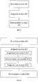
- the device for identifying an action includes: a recording module 401 configured to record vibration trajectory information for vibration of an intelligent device from start to stabilization of the vibration; a judgment module 402 configured to determine whether the vibration is a damping vibration based on the vibration trajectory information; and a determination module 403 configured to determine that the vibration is caused by a user's trigger action in the case that the vibration is a damping vibration.
- a condition that the intelligent device generates a damping vibration merely is to receive an impact force, rather than vibration generated by movement of the intelligent device, so that the intelligent device can recognize that the vibration is caused by a user's trigger action, without requiring human-machine interaction by using keyboard or remote control, and thus user's experience can be improved.
- the judgment module 402 may include: an acquisition sub-module 4021 configured to acquire, based on the vibration trajectory information, position information of n first peaks and n first troughs of the vibrationn trajectory information in time order, wherein n is a positive integer; a determination sub-module 4022 configured to determine, according to the position information of the n first peaks and the n first troughs, n first amplitude distances between respective adjacent peaks and troughs in amplitude direction; and a judgment sub-module 4023 configured to judge whether the n first amplitude distances successively decrease in time order; wherein it is determined that the vibration is a damping vibration in the case that the n first amplitude distances successively decrease, and it is determined that the vibration is not a damping vibration in the case that the n first amplitude distances do not successively decrease.
- the judgment sub-module 4023 may be configured to: judge whether the first amplitude distance in the n first amplitude distances is greater than a preset distance; and judge whether the n first amplitude distances successively decrease in the case that the first amplitude distance is greater than the preset distance.
- the acquisition sub-module 4021 may be configured to: acquire the total number of all peaks and troughs of the vibration trajectory information; and acquire the position information of n first peaks and n first troughs of the vibration trajectory information in time order in the case that the total number of all peaks and troughs is greater than or equal to 2n.
- the recording module 401 may include: a collection sub-module 4011 configured to collet vibration trajectory information for the vibration in a preset direction by using a gravity sensor.
- a device for identifying an action which is used for interactive control of an intelligent device.
- the device includes: a processor; a memory for storing instructions executable by the processor, wherein the processor is configured to: record vibration trajectory information for vibration of an intelligent device from start to stabilization of the vibration; judge whether the vibration is a damping vibration based on the vibration trajectory information; and determine that the vibration is caused by a user's trigger action in the case that the vibration is a damping vibration.
- the processor may be configured to: acquire, based on the vibration trajectory information, position information of n first peaks and n first troughs of the vibration trajectory information in time order, wherein n is a positive integer; determine, according to the position information of the n first peaks and the n first troughs, n first amplitude distances between respective adjacent peaks and troughs in amplitude direction; and judging whether the n first amplitude distances successively decrease in time order, wherein it is determined that the vibration is a damping vibration in the case that the n first amplitude distances successively decrease, and it is determined that the vibration is not a damping vibration in the case that the n first amplitude distances do not successively decrease.
- the judging whether the n first amplitude distances successively decrease in time order may include: judging whether the first amplitude distance in the n first amplitude distances is greater than a preset distance; and judging whether the n first n amplitude distances successively decrease in the case that the first amplitude distance is greater than the preset distance.
- the acquiring, based on the vibration trajectory information, position information of n first peaks and n first troughs of the vibration trajectory information in time order may include: acquiring the total number of all peaks and troughs of the vibration trajectory information; and acquiring the position information of n first peaks and n first troughs of the vibration trajectory information in time order in the case that the total number of all peaks and troughs is greater than or equal to 2n.
- the recording vibration trajectory information for vibration of an intelligent device from start to stabilization of the vibration may include: collecting vibration trajectory information for the vibration in a preset direction by using a gravity sensor.
- Figure 8 is a block diagram of a device for identifying an action according to some exemplary embodiments.
- the device is applicable to a terminal device.
- the device 1700 may be a mobile phone, a computer, a digital broadcast terminal, a messaging device, a gaming console, a tablet, a medical device, an exercise equipment, a personal digital assistant, and the like.
- the device 1700 may include one or more of the following components: a processing component 1702, a memory 1704, a power component 1706, a multimedia component 1708, an audio component 1710, an input/output (I/O) interface 1712, a sensor component 1714, and a communication component 1716.
- the processing component 1702 typically controls overall operations of the device 1700, such as the operations associated with display, telephone calls, data communications, camera operations, and recording operations.
- the processing component 1702 may include one or more processors 1720 to execute instructions to perform all or part of the steps in the above described methods.
- the processing component 1702 may include one or more modules which facilitate the interaction between the processing component 1702 and other components.
- the processing component 1702 may include a multimedia module to facilitate the interaction between the multimedia component 1708 and the processing component 1702.
- the memory 1704 is configured to store various types of data to support the operation of the device 1700. Examples of such data include instructions for any applications or methods operated on the device 1700, contact data, phonebook data, messages, pictures, video, etc.
- the memory 1704 may be implemented using any type of volatile or non-volatile memory devices, or a combination thereof, such as a static random access memory (SRAM), an electrically erasable programmable read-only memory (EEPROM), an erasable programmable read-only memory (EPROM), a programmable read-only memory (PROM), a read-only memory (ROM), a magnetic memory, a flash memory, a magnetic or optical disk.
- SRAM static random access memory
- EEPROM electrically erasable programmable read-only memory
- EPROM erasable programmable read-only memory
- PROM programmable read-only memory
- ROM read-only memory
- magnetic memory a magnetic memory
- flash memory a flash memory
- magnetic or optical disk a magnetic
- the power component 1706 provides power to various components of the device 1700.
- the power component 1706 may include a power management system, one or more power sources, and any other components associated with the generation, management, and distribution of power in the device 1700.
- the multimedia component 1708 includes a screen providing an output interface between the device 1700 and the user.
- the screen may include a liquid crystal display (LCD) and a touch panel (TP). If the screen includes the touch panel, the screen may be implemented as a touch screen to receive input signals from the user.
- the touch panel includes one or more touch sensors to sense touches, swipes, and gestures on the touch panel. The touch sensors may not only sense a boundary of a touch or swiping action, but also sense a period of time and a pressure associated with the touch or swiping action.
- the multimedia component 1708 includes a front camera and/or a rear camera. The front camera and the rear camera may receive an external multimedia datum while the device 1700 is in an operation mode, such as a photographing mode or a video mode. Each of the front camera and the rear camera may be a fixed optical lens system or have focus and optical zoom capability.
- the audio component 1710 is configured to output and/or input audio signals.
- the audio component 1710 includes a microphone ("MIC") configured to receive an external audio signal when the device 1700 is in an operation mode, such as a call mode, a recording mode, and a voice recognition mode.
- the received audio signal may be further stored in the memory 1704 or transmitted via the communication component 1716.
- the audio component 1710 further includes a speaker to output audio signals.
- the I/O interface 1712 provides an interface between the processing component 1702 and peripheral interface modules, such as a keyboard, a click wheel, buttons, etc.
- peripheral interface modules such as a keyboard, a click wheel, buttons, etc.
- the buttons may include, but are not limited to, a home button, a volume button, a starting button, and a locking button.
- the sensor component 1714 includes one or more sensors to provide status assessments of various aspects of the device 1700. For instance, the sensor component 1714 may detect an open/closed status of the device 1700, relative positioning of components, e.g., the display and the keypad, of the device 1700. The sensor component 1714 may further detect a change in position of the device 1700 or a component of the device 1700, a presence or absence of user contact with the device 1700, an orientation or an acceleration/deceleration of the device 1700, and a change in temperature of the device 1700. The sensor component 1714 may include a proximity sensor configured to detect the presence of nearby objects without any physical contact.
- the sensor component 1714 may also include a light sensor, such as a CMOS or CCD image sensor, for use in imaging applications.
- the sensor component 1714 may also include an accelerometer sensor, a gyroscope sensor, a magnetic sensor, a pressure sensor, or a temperature sensor.
- the communication component 1716 is configured to facilitate communication, wired or wirelessly, between the device 1700 and other devices.
- the device 1700 can access a wireless network based on a communication standard, such as WiFi, 2G, or 3G, or a combination thereof.
- the communication component 1716 receives a broadcast signal or broadcast associated information from an external broadcast management system via a broadcast channel.
- the communication component 1716 further includes a near field communication (NFC) module to facilitate short-range communications.
- the NFC module may be implemented based on a radio frequency identification (RFID) technology, an infrared data association (IrDA) technology, an ultra-wideband (UWB) technology, a Bluetooth (BT) technology, and other technologies.
- RFID radio frequency identification
- IrDA infrared data association
- UWB ultra-wideband
- BT Bluetooth
- the device 1700 may be implemented with one or more application specific integrated circuits (ASICs), digital signal processors (DSPs), digital signal processing devices (DSPDs), programmable logic devices (PLDs), field programmable gate arrays (FPGAs), controllers, micro-controllers, microprocessors, or other electronic components, for performing the above described methods.
- ASICs application specific integrated circuits
- DSPs digital signal processors
- DSPDs digital signal processing devices
- PLDs programmable logic devices
- FPGAs field programmable gate arrays
- controllers micro-controllers, microprocessors, or other electronic components, for performing the above described methods.
- non-transitory computer-readable storage medium including instructions, such as included in the memory 1704, executable by the processor 1720 in the device 1700, for performing the above-described methods.
- the non-transitory computer-readable storage medium may be a ROM, a RAM, a CD-ROM, a magnetic tape, a floppy disc, an optical data storage device, and the like.
- a non-temporary computer readable storage medium that enables the device 1700 to perform the method for identifying an action when the instructions in the storage medium are executed by the processor of the device 1700.
- the method includes: recording vibration trajectory information for vibration of an intelligent device from start to stabilization of the vibration; judging whether the vibration is a damping vibration based on the vibration trajectory information; and determining that the vibration is caused by a user's trigger action in the case that the vibration is a damping vibration.
- the judging whether the vibration is a damping vibration based on the vibration trajectory information may include: acquiring, based on the vibration trajectory information, position information of n first peaks and n first troughs of the vibration trajectory information in time order, wherein n is a positive integer; determining, according to the position information of the n first peaks and the n first troughs, n first amplitude distances between respective adjacent peaks and troughs in amplitude direction; and judging whether the n first amplitude distances are successively decreased in time order, wherein it is determined that the vibration is a damping vibration in the case that the n first amplitude distances successively decrease, and it is determined that the vibration is not a damping vibration in the case that the n first amplitude distances do not successively decrease.
- the judging whether the n first amplitude distances successively decrease in time order may include: judging whether the first amplitude distance in the n first amplitude distances is greater than a preset distance; and judging whether the n first amplitude distances successively decrease in the case that the first amplitude distance is greater than the preset distance.
- the acquiring, based on the vibration trajectory information, position information of first n peaks and first n troughs of the vibration trajectory information in time order may include: acquiring the total number of all peaks and troughs of the vibration trajectory information; and acquiring the position information of n first peaks and n first troughs of the vibration trajectory information in time order in the case that the total number of all peaks and troughs is greater than or equal to 2n.
- the recording vibration trajectory information for vibration of an intelligent device from start to stabilization of the vibration may include: collecting vibration trajectory information for the vibration in a preset direction by using a gravity sensor.
Landscapes
- Engineering & Computer Science (AREA)
- General Engineering & Computer Science (AREA)
- Theoretical Computer Science (AREA)
- Physics & Mathematics (AREA)
- General Physics & Mathematics (AREA)
- Human Computer Interaction (AREA)
- Computer Hardware Design (AREA)
- Mechanical Engineering (AREA)
- Automation & Control Theory (AREA)
- Computer Networks & Wireless Communication (AREA)
- Signal Processing (AREA)
- Acoustics & Sound (AREA)
- Aviation & Aerospace Engineering (AREA)
- User Interface Of Digital Computer (AREA)
Abstract
Description
- The present disclosure relates to the field of communication technology, and more particularly to methods and devices for identifying an action.
- Electrical fans are household appliances that utilize a motor to drive rotation of fan blades in order to speed up air flow, and in turn achieve air circulation and cooling. Every summer, electrical fans are used to provide bring air cooling for humans with lower energy consumption than air conditioners.
- In accordance with some embodiments of the disclosed subject matter, methods and devices for identifying an action are provided. Various technical solutions are described below.
- According to a first aspect of embodiments of the present disclosure, there is provided a method for identifying an action, which is used for interactive control of an intelligent device. The method includes: recording vibration trajectory information for vibration of an intelligent device from start to stabilization of the vibration; judging whether the vibration is a damping vibration based on the vibration trajectory information; and determining that the vibration is caused by a user's trigger action in the case that the vibration is a damping vibration.
- The technical solution provided by embodiments of the present disclosure can provide the following beneficial effects: a condition that the intelligent device generates a damping vibration merely is to receive an impact force, rather than vibration generated by movement of the intelligent device, so that the intelligent device can recognize that the vibration is caused by a user's trigger action, without requiring human-machine interaction by using keyboard or remote control, and thus user's experience can be improved.
- In some embodiments, the judging whether the vibration is a damping vibration based on the vibration trajectory information includes: acquiring, based on the vibration trajectory information, position information of n first peaks and n first troughs of the vibrationn trajectory information in time order, wherein n is a positive integer; determining, according to the position information of the n first peaks and the n first troughs, n first amplitude distances between respective adjacent peaks and troughs in amplitude direction; and judging whether the n first amplitude distances successively decrease in time order; wherein it is determined that the vibration is a damping vibration in the case that the n first amplitude distances successively decrease, and it is determined that the vibration is not a damping vibration in the case that the n first amplitude distances do not successively decrease.
- The technical solution provided by embodiments of the present disclosure can provide the following beneficial effects: it is able to determine whether the vibration is a damping vibration by judging attenuation of amplitude distances, by which results can be obtained intuitively without complicated process and calculation efficiency can be improved.
- In some embodiments, the judging whether the n first amplitude distances are successively decreased in time order includes: judging whether the first amplitude distance in the n first amplitude distances is greater than a preset distance; and judging whether the n first amplitude distances are successively decreased in the case that the first amplitude distance is greater than the preset distance.
- The technical solution provided by embodiments of the present disclosure can provide the following beneficial effects: it is able to exclude vibrations caused by misoperations or environmental influences, and thus accuracy of action identification can be improved.
- In some embodiments, the acquiring, based on the vibration trajectory information, position information of n first peaks and n first troughs of the vibration trajectory information in time order includes: acquiring the total number of all peaks and troughs of the vibration trajectory information; and acquiring the position information of n first peaks and n first troughs of the vibration trajectory information in time order in the case that the total number of all peaks and troughs is greater than or equal to 2n.
- The technical solution provided by embodiments of the present disclosure can provide the following beneficial effects: it is able to ignore minute vibrations to further exclude vibrations caused by misoperations or environmental influences.
- In some embodiments, the recording vibration trajectory information for vibration of an intelligent device from start to stabilization of the vibration includes: collecting vibration trajectory information for the vibration in a preset direction by using a gravity sensor.
- The technical solution provided by embodiments of the present disclosure can provide the following beneficial effects: it is able to improve accuracy of action identification by acquiring only vibrations in the preset direction because vibrations in the preset direction are the largest.
- According to a second aspect of embodiments of the present disclosure, there is provided a device for identifying an action, which is used for interactive control of an intelligent device. The device includes: a recording module configured to record vibration trajectory information for vibration of an intelligent device from start to stabilization of the vibration; a judgment module configured to determine whether the vibration is a damping vibration based on the vibration trajectory information; and a determination module configured to determine that the vibration is caused by a user's trigger action in the case that the vibration is a damping vibration.
- In some embodiments, the judgment module includes: an acquisition sub-module configured to acquire, based on the vibration trajectory information, position information of n first peaks and n first troughs of the vibrationn trajectory information in time order, wherein n is a positive integer; a determination sub-module configured to determine, according to the position information of the n first peaks and the n first troughs, n first amplitude distances between respective adjacent peaks and troughs in amplitude direction; and a judgment sub-module configured to judge whether the n first amplitude distances successive decrease in time order; wherein it is determined that the vibration is a damping vibration in the case that the n first amplitude distances successively decrease, and it is determined that the vibration is not a damping vibration in the case that the n first amplitude distances do not successively decrease.
- In some embodiments, the judgment sub-module is configured to: judge whether the first amplitude distance in the n first amplitude distances is greater than a preset distance; and judge whether the n first amplitude distances successively decrease in the case that the first amplitude distance is greater than the preset distance.
- In some embodiments, the acquisition sub-module is configured to: acquiring the total number of all peaks and troughs of the vibration trajectory information; and acquiring the position information of n first peaks and n first troughs of the vibration trajectory information in time order in the case that the total number of all peaks and troughs is greater than or equal to 2n.
- In some embodiments, the recording module includes: a collection sub-module configured to collet vibration trajectory information for the vibration in a preset direction by using a gravity sensor.
- According to a third aspect of embodiments of the present disclosure, there is provided a device for identifying an action, which is used for interactive control of an intelligent device. The device includes: a processor; a memory for storing instructions executable by the processor, wherein the processor is configured to: record vibration trajectory information for vibration of an intelligent device from start to stabilization of the vibration; judge whether the vibration is a damping vibration based on the vibration trajectory information; and determine that the vibration is caused by a user's trigger action in the case that the vibration is a damping vibration.
- It is to be understood that both the foregoing general descriptions and the following detailed descriptions are exemplary and explanatory only and do not limit the scope of the disclosure.
- The drawings herein are incorporated in and constitute a part of this specification, showing embodiments consistent with the present disclosure, and together with the descriptions, serve to explain the principles of the present disclosure.
-
Figure 1 is a flow chart of a method for identifying an action according to some exemplary embodiments. -
Figure 2 is a schematic view of a fan head of an electrical fan according to some exemplary embodiments. -
Figure 3 is a flow chart of a method for identifying an action according to some exemplary embodiments. -
Figure 4 is a flow chart of a method for identifying an action according to some exemplary embodiments. -
Figure 5 is a block diagram of a device for identifying an action according to some exemplary embodiments. -
Figure 6 is a block diagram of a device for identifying an action according to some exemplary embodiments. - Figure is a block diagram of a device for identifying an action according to some exemplary embodiments.
-
Figure 8 is a block diagram of a device for identifying an action according to some exemplary embodiments. - Hereinafter, exemplary embodiments will be described in detail, examples of which are shown in the drawings. In the following descriptions when referring to the drawings, the same numerals in the different drawings denote the same or similar elements unless otherwise indicated. The embodiments described in the following exemplary embodiments are not representative of all embodiments consistent with the present disclosure. Rather, they are merely examples of apparatuses and methods consistent with some aspects of the present disclosure as detailed in the appended claims.
- In related art, techniques for achieving interactive control of an intelligent device mainly concentrate on utilization of a keyboard or a remote control. For example, an electrical fan is an essential object for many families, but human-machine interaction supported by current electric fans is limited to utilization of a keyboard or a remote control. For the keyboard, it takes up a large part of a panel of the electrical fan and requires press of a particular button thereon; for the remote control, it is often cannot be found by a user, and since it has smaller buttons, it is difficult for the user to operate.
-
Figure 1 is a flow chart of a method for identifying an action according to some exemplary embodiment. As shown inFigure 1 , the method is applicable to a device for identifying an action, which can be used for interactive control of an intelligent device. The method include thefollowing steps 101 to 103. - In
step 101, vibration trajectory information for vibration of an intelligent device from start to stabilization of the vibration is recorded. - Vibration intensity may vary depending on a position at which vibration trajectory information is recorded. Therefore, the position for recording vibration needs to be set in advance. In general, the position for recording vibration may be set at a position at which a trigger action is to be performed.
- When the intelligent device itself receives a force from outside, it vibrates. The device senses and records vibration trajectory information of an entire procedure of the vibration from start to stabilization thereof. The vibration trajectory information may be collected by a sensor provided in the device. The vibration trajectory information may include position information of vibration points and corresponding timing information. The vibration may be vibration of the whole intelligent device or vibration of one or more of components of the intelligent device. Here, the procedure from start to stabilization of vibration may be a procedure from a time point at which the intelligent device starts to wobble to a time point at which the intelligent device stops wobbling, by which the vibration trajectory information is generated as information about vibration trajectory. The vibration trajectory is a movement trajectory described by an x-axis indicating corresponding to time and a y-axis corresponding to amplitude of vibration, where a maximum point in the trajectory is a peak and a minimum point is a trough.
- In
step 102, a judgment as to whether the vibration is a damping vibration is made based on the vibration trajectory information. - Damping vibration is a vibration which is caused when a vibration system experiences friction force, dielectric resistance and/or other energy consumption and has its amplitude gradually reduced over time. Damping vibration is sometimes referred to as decrement vibration or attenuation vibration.
- Therefore, it is possible to determine whether t the vibration is a damping vibration based on the vibration trajectory information. For example, it is possible to determine amplitude from the vibration trajectory information and determine whether it is a damping vibration based on attenuation of the amplitude. Alternatively, it is possible to determine a distance between a peak and a trough in amplitude direction from the vibration trajectory information, and determine whether it is a damping vibration according to attenuation of the distance. The method of the present embodiment is not limited thereto.
- In
step 103, it is determined that the vibration is caused by a user's trigger action in the case that the vibration is a damping vibration. - In some embodiments, the user's trigger action may be performed on a preset area. The preset area is an area set on the device that is designated in advance, in which the user can perform a trigger action and the device can sense the action noticeably. The sensor for sensing vibration can be set in the preset area.
- In an example of the electrical fan, the manufacturer can set a rule (which allows a trigger action to be performed on a front surface of the fan head). The preset area may be located any position on a surface of the fan head of the electrical fan accessible by the user, as shown in
Figure 2 . If the preset area is located on the center of the surface facing the user, not only the user's hand will not be hurt when the user performs a trigger action at this position, but also the electrical fan can sense its maximum vibration.Figure 2 does not show fan blades, but this does not mean that there is no fan blades in the fan head. - In some embodiments, upon determination that the vibration is generated by the user's trigger action acting in the preset area, an operation corresponding to the trigger action can be performed, for example, turn on/off of the device, adjustment of gears of the device. The trigger action generally may be a knock operation, a tap operation. The present embodiment is not limited, as long as the operation can impart a force to the device and ensure vibration of the device.
- In some embodiments, as long as a damping vibration is determined, it can prove at least that the vibration is not due to wobbling caused by the user carrying the device.
- In some embodiments, a condition that the intelligent device generates a damping vibration merely is to receive an impact force, rather than vibration generated by movement of the intelligent device, so that the intelligent device can recognize that the vibration is caused by a user's trigger action, without requiring human-machine interaction by using keyboard or remote control, and thus user's experience can be improved.
- In some embodiments, the
step 102 may include: acquiring, based on the vibration trajectory information, position information of n first peaks and n first troughs of the vibration trajectory information in time order, wherein n is a positive integer; determining, according to the position information of the n first peaks and the n first troughs, first n amplitude distances between respective adjacent peaks and troughs in amplitude direction; and judging whether the n first amplitude distances successively decrease in time order; wherein it is determined that the vibration is a damping vibration in the case that the n first amplitude distances successively decrease, and it is determined that the vibration is not a damping vibration in the case that the n first amplitude distances do not successively decrease. - In some embodiments, the determining, according to the position information of the n first peaks and the n first troughs, n first amplitude distances between respective adjacent peaks and troughs in amplitude direction may include: determining, according to the position information of the ith peak and the ith trough, the ith amplitude distance, wherein i is an integer from 1 to n, and n may be 4.
- In some embodiments, the judging whether the first n amplitude distances are successively decreased in time order may include: sorting the n first amplitude distances in time order; determine whether the jth amplitude distance is greater than the (j+1)th amplitude distance, wherein j is an integer from 1 to n-1; determining that the vibration is a damping vibration in the case that n-1 first amplitude distances are all greater than their respective subsequent amplitude distances. If there is at least one amplitude distance among the n-1 amplitude distances that is smaller than or equal to its subsequent amplitude distance, it is considered that the vibration is not a damping vibration.
- As an example, in the case where n=4, the first four amplitude distances are sorted in time forward order, and it is judged whether the first amplitude distance is greater than the second amplitude distance, whether the second amplitude distance is greater than the third amplitude distance, and whether the third amplitude distance is greater than the fourth amplitude distance. If yes for all of them, the vibration is a damping vibration; if no for at least one of them, the vibration is not a damping vibration.
- In some embodiments, the judging whether the n first amplitude distances successively decrease in time order may include: judging whether the first amplitude distance in the n first amplitude distances is greater than a preset distance; and judging whether the n first amplitude distances successively decrease in the case that the first amplitude distance is greater than the preset distance.
- In order to exclude a damping vibration caused by accidental touch by a user or caused by ambient wind, it is necessary to judge whether the first amplitude distance in time forward sequence is greater than the preset distance, and if it is not greater than that, the power of the vibration is relatively small, and thus it is not caused by the user's trigger action.
- It should be understood that when a user performs a trigger action on the fan, first wobbling of the fan is the largest, and then the fan swings on its own with its amplitude being slowly narrowed until balance. Thus, the judgment is to avoid false trigger caused when the user is wobbling the fan or moving with the fan.
- In some embodiments, the acquiring, based on the vibration trajectory information, position information of n first peaks and n first troughs of the vibration trajectory information in time order may include: acquiring the total number of all peaks and troughs of the vibration trajectory information; and acquiring the position information of n first peaks and n first troughs of the vibration trajectory information in time order in the case that the total number of all peaks and troughs is greater than or equal to 2n.
- In order to further exclude a damping vibration caused by accidental touch by a user or caused by ambient wind, it is necessary to ensure that there is enough number of fluctuations in vibration, so determination of the number of peaks and troughs is required.
- In some embodiments, the
step 101 may include: collecting vibration trajectory information for the vibration in a preset direction using a gravity sensor. - The preset direction is a direction set by the manufacturer in advance, and may vary depending on different devices. In an example of the electrical fan, it may be set that a trigger action (such as knock, tap and the like) is only allowed to be performed by a user on a surface (front surface) of fan head of the electrical fan facing the user side. Thus, in order to simplify acquisition of vibration trajectory information, the device can acquire only information at a position having largest variation. Clearly, variation in position information of a position in a vertical direction of front surface of the fan head is the largest and most useful. In general, the vertical direction of front surface of the fan head is a horizontal direction. The preset direction may also be other preset directions such as the vertical direction. The present disclosure is not limited thereto.
- In some embodiments, the
step 103 may include: performing, in the case that the vibration is a damping vibration, a trigger instruction corresponding to the vibration. -
Figure 3 is a flow chart of a method for identifying an action according to some exemplary embodiments. As shown inFigure 3 , the method is applicable to a device for identifying an action, which can be used for intelligent interaction with an electrical fan. The method include the followingsteps 201 to 205. - In
step 201, vibration trajectory information of vibration in a horizontal direction is collected by a gravity sensor. - For the electrical fan, the preset direction is a horizontal direction.
- In
step 202, based on the vibration trajectory information, position information of n first peaks and n first troughs of the vibration trajectory information is acquired in time order. - In
step 203, according to the position information of the n first peaks and the n first troughs, n first amplitude distances between respective adjacent peaks and troughs in amplitude direction are determined. - In
step 204, a judgment as to whether the n first amplitude distances successively decrease in time order is made. - In
step 205, in the case that the n first amplitude distances successively decrease, it is determined that the vibration is generated by a user's trigger action in a preset area. - In the present embodiment, it is able to determine that the vibration is a damping vibration by successive decrease in the amplitude distances, and thus determine that the vibration is triggered by the user, and thereby human-machine interaction is achieved and the user's experience can be improved.
-
Figure 4 is a flow chart of a method for identifying an action according to some exemplary embodiments. As shown inFigure 4 , the method is applicable to a device for identifying an action, which can be used for intelligent interaction with an electrical fan. The method include the followingsteps 301 to 308. - In
step 301, vibration trajectory information of vibration in a height direction with respect to the horizontal plane is collected by a gravity sensor. - For the electrical fan, the preset direction is a longitudinal direction of the electrical fan.
- In
step 302, the total number of all peaks and troughs of the vibration trajectory information are acquired. - In
step 303, a determination as to whether the total number of all peaks and troughs is greater than or equal to 2n is made. If yes, step 304 is performed; if not, the process is ended. - In
step 304, position information of n first peaks and n first troughs of the vibrationn trajectory information is acquired in time order. - In
step 305, according to the position information of the n first peaks and the n first troughs, n first n amplitude distances between respective adjacent peaks and troughs in amplitude direction are determined. - In
step 306, a judgment as to whether the first one in the n first amplitude distances is greater than a preset distance. If yes, step 307 is performed; if not, the process is ended. - In
step 307, a judgment as to whether the n first amplitude distances successively decrease in time order is made. If yes, step 308 is performed; if not, the process is ended. - In
step 308, it is determined that the vibration is generated by a user's trigger action. - In the present embodiment, by setting conditions for the vibration, such as a minimum value of the first amplitude distance and the number of peaks and troughs of the vibration, it is able to avoid false trigger occurred when the user are wobbling the fan or are moving with the fan, and thus ensure that the vibration is triggered by the user giving to the fan a force and thereby accuracy of action identification can be improved.
- The following is a device embodiment of the present disclosure, which is applicable to carry out the method embodiments of the present disclosure.
-
Figure 5 is a block diagram of a device for identifying an action according to some exemplary embodiments. The device is applicable to interactive control of an intelligent device, and can be implemented as part or all of an electronic device by software, hardware, or a combination of both. As shown inFigure 5 , the device for identifying an action includes: arecording module 401 configured to record vibration trajectory information for vibration of an intelligent device from start to stabilization of the vibration; ajudgment module 402 configured to determine whether the vibration is a damping vibration based on the vibration trajectory information; and adetermination module 403 configured to determine that the vibration is caused by a user's trigger action in the case that the vibration is a damping vibration. - In the present embodiment, a condition that the intelligent device generates a damping vibration merely is to receive an impact force, rather than vibration generated by movement of the intelligent device, so that the intelligent device can recognize that the vibration is caused by a user's trigger action, without requiring human-machine interaction by using keyboard or remote control, and thus user's experience can be improved.
- In some embodiments, as shown in
Figure 6 , thejudgment module 402 may include: an acquisition sub-module 4021 configured to acquire, based on the vibration trajectory information, position information of n first peaks and n first troughs of the vibrationn trajectory information in time order, wherein n is a positive integer; a determination sub-module 4022 configured to determine, according to the position information of the n first peaks and the n first troughs, n first amplitude distances between respective adjacent peaks and troughs in amplitude direction; and a judgment sub-module 4023 configured to judge whether the n first amplitude distances successively decrease in time order; wherein it is determined that the vibration is a damping vibration in the case that the n first amplitude distances successively decrease, and it is determined that the vibration is not a damping vibration in the case that the n first amplitude distances do not successively decrease. - In an embodiment, the
judgment sub-module 4023 may be configured to: judge whether the first amplitude distance in the n first amplitude distances is greater than a preset distance; and judge whether the n first amplitude distances successively decrease in the case that the first amplitude distance is greater than the preset distance. - In some embodiments, the acquisition sub-module 4021 may be configured to: acquire the total number of all peaks and troughs of the vibration trajectory information; and acquire the position information of n first peaks and n first troughs of the vibration trajectory information in time order in the case that the total number of all peaks and troughs is greater than or equal to 2n.
- In some embodiments, as shown in
Figure 7 , therecording module 401 may include: acollection sub-module 4011 configured to collet vibration trajectory information for the vibration in a preset direction by using a gravity sensor. - In some embodiments, there is provided a device for identifying an action, which is used for interactive control of an intelligent device. The device includes: a processor; a memory for storing instructions executable by the processor, wherein the processor is configured to: record vibration trajectory information for vibration of an intelligent device from start to stabilization of the vibration; judge whether the vibration is a damping vibration based on the vibration trajectory information; and determine that the vibration is caused by a user's trigger action in the case that the vibration is a damping vibration.
- The processor may be configured to: acquire, based on the vibration trajectory information, position information of n first peaks and n first troughs of the vibration trajectory information in time order, wherein n is a positive integer; determine, according to the position information of the n first peaks and the n first troughs, n first amplitude distances between respective adjacent peaks and troughs in amplitude direction; and judging whether the n first amplitude distances successively decrease in time order, wherein it is determined that the vibration is a damping vibration in the case that the n first amplitude distances successively decrease, and it is determined that the vibration is not a damping vibration in the case that the n first amplitude distances do not successively decrease.
- The judging whether the n first amplitude distances successively decrease in time order may include: judging whether the first amplitude distance in the n first amplitude distances is greater than a preset distance; and judging whether the n first n amplitude distances successively decrease in the case that the first amplitude distance is greater than the preset distance.
- The acquiring, based on the vibration trajectory information, position information of n first peaks and n first troughs of the vibration trajectory information in time order may include: acquiring the total number of all peaks and troughs of the vibration trajectory information; and acquiring the position information of n first peaks and n first troughs of the vibration trajectory information in time order in the case that the total number of all peaks and troughs is greater than or equal to 2n.
- The recording vibration trajectory information for vibration of an intelligent device from start to stabilization of the vibration may include: collecting vibration trajectory information for the vibration in a preset direction by using a gravity sensor.
- With respect to the devices of the above embodiments, the specific mode in which each module performs the operation has been described in detail in the embodiment relating to the method, and the description thereof will not be described in detail herein.
-
Figure 8 is a block diagram of a device for identifying an action according to some exemplary embodiments. The device is applicable to a terminal device. For example, thedevice 1700 may be a mobile phone, a computer, a digital broadcast terminal, a messaging device, a gaming console, a tablet, a medical device, an exercise equipment, a personal digital assistant, and the like. - The
device 1700 may include one or more of the following components: aprocessing component 1702, amemory 1704, apower component 1706, amultimedia component 1708, anaudio component 1710, an input/output (I/O)interface 1712, asensor component 1714, and acommunication component 1716. - The
processing component 1702 typically controls overall operations of thedevice 1700, such as the operations associated with display, telephone calls, data communications, camera operations, and recording operations. Theprocessing component 1702 may include one ormore processors 1720 to execute instructions to perform all or part of the steps in the above described methods. Moreover, theprocessing component 1702 may include one or more modules which facilitate the interaction between theprocessing component 1702 and other components. For instance, theprocessing component 1702 may include a multimedia module to facilitate the interaction between themultimedia component 1708 and theprocessing component 1702. - The
memory 1704 is configured to store various types of data to support the operation of thedevice 1700. Examples of such data include instructions for any applications or methods operated on thedevice 1700, contact data, phonebook data, messages, pictures, video, etc. Thememory 1704 may be implemented using any type of volatile or non-volatile memory devices, or a combination thereof, such as a static random access memory (SRAM), an electrically erasable programmable read-only memory (EEPROM), an erasable programmable read-only memory (EPROM), a programmable read-only memory (PROM), a read-only memory (ROM), a magnetic memory, a flash memory, a magnetic or optical disk. - The
power component 1706 provides power to various components of thedevice 1700. Thepower component 1706 may include a power management system, one or more power sources, and any other components associated with the generation, management, and distribution of power in thedevice 1700. - The
multimedia component 1708 includes a screen providing an output interface between thedevice 1700 and the user. In some embodiments, the screen may include a liquid crystal display (LCD) and a touch panel (TP). If the screen includes the touch panel, the screen may be implemented as a touch screen to receive input signals from the user. The touch panel includes one or more touch sensors to sense touches, swipes, and gestures on the touch panel. The touch sensors may not only sense a boundary of a touch or swiping action, but also sense a period of time and a pressure associated with the touch or swiping action. In some embodiments, themultimedia component 1708 includes a front camera and/or a rear camera. The front camera and the rear camera may receive an external multimedia datum while thedevice 1700 is in an operation mode, such as a photographing mode or a video mode. Each of the front camera and the rear camera may be a fixed optical lens system or have focus and optical zoom capability. - The
audio component 1710 is configured to output and/or input audio signals. For example, theaudio component 1710 includes a microphone ("MIC") configured to receive an external audio signal when thedevice 1700 is in an operation mode, such as a call mode, a recording mode, and a voice recognition mode. The received audio signal may be further stored in thememory 1704 or transmitted via thecommunication component 1716. In some embodiments, theaudio component 1710 further includes a speaker to output audio signals. - The I/
O interface 1712 provides an interface between theprocessing component 1702 and peripheral interface modules, such as a keyboard, a click wheel, buttons, etc. The buttons may include, but are not limited to, a home button, a volume button, a starting button, and a locking button. - The
sensor component 1714 includes one or more sensors to provide status assessments of various aspects of thedevice 1700. For instance, thesensor component 1714 may detect an open/closed status of thedevice 1700, relative positioning of components, e.g., the display and the keypad, of thedevice 1700. Thesensor component 1714 may further detect a change in position of thedevice 1700 or a component of thedevice 1700, a presence or absence of user contact with thedevice 1700, an orientation or an acceleration/deceleration of thedevice 1700, and a change in temperature of thedevice 1700. Thesensor component 1714 may include a proximity sensor configured to detect the presence of nearby objects without any physical contact. Thesensor component 1714 may also include a light sensor, such as a CMOS or CCD image sensor, for use in imaging applications. In some embodiments, thesensor component 1714 may also include an accelerometer sensor, a gyroscope sensor, a magnetic sensor, a pressure sensor, or a temperature sensor. - The
communication component 1716 is configured to facilitate communication, wired or wirelessly, between thedevice 1700 and other devices. Thedevice 1700 can access a wireless network based on a communication standard, such as WiFi, 2G, or 3G, or a combination thereof. In some exemplary embodiments, thecommunication component 1716 receives a broadcast signal or broadcast associated information from an external broadcast management system via a broadcast channel. In some exemplary embodiments, thecommunication component 1716 further includes a near field communication (NFC) module to facilitate short-range communications. For example, the NFC module may be implemented based on a radio frequency identification (RFID) technology, an infrared data association (IrDA) technology, an ultra-wideband (UWB) technology, a Bluetooth (BT) technology, and other technologies. - In exemplary embodiments, the
device 1700 may be implemented with one or more application specific integrated circuits (ASICs), digital signal processors (DSPs), digital signal processing devices (DSPDs), programmable logic devices (PLDs), field programmable gate arrays (FPGAs), controllers, micro-controllers, microprocessors, or other electronic components, for performing the above described methods. - In exemplary embodiments, there is also provided a non-transitory computer-readable storage medium including instructions, such as included in the
memory 1704, executable by theprocessor 1720 in thedevice 1700, for performing the above-described methods. For example, the non-transitory computer-readable storage medium may be a ROM, a RAM, a CD-ROM, a magnetic tape, a floppy disc, an optical data storage device, and the like. - A non-temporary computer readable storage medium that enables the
device 1700 to perform the method for identifying an action when the instructions in the storage medium are executed by the processor of thedevice 1700. The method includes: recording vibration trajectory information for vibration of an intelligent device from start to stabilization of the vibration; judging whether the vibration is a damping vibration based on the vibration trajectory information; and determining that the vibration is caused by a user's trigger action in the case that the vibration is a damping vibration. - The judging whether the vibration is a damping vibration based on the vibration trajectory information may include: acquiring, based on the vibration trajectory information, position information of n first peaks and n first troughs of the vibration trajectory information in time order, wherein n is a positive integer; determining, according to the position information of the n first peaks and the n first troughs, n first amplitude distances between respective adjacent peaks and troughs in amplitude direction; and judging whether the n first amplitude distances are successively decreased in time order, wherein it is determined that the vibration is a damping vibration in the case that the n first amplitude distances successively decrease, and it is determined that the vibration is not a damping vibration in the case that the n first amplitude distances do not successively decrease.
- The judging whether the n first amplitude distances successively decrease in time order may include: judging whether the first amplitude distance in the n first amplitude distances is greater than a preset distance; and judging whether the n first amplitude distances successively decrease in the case that the first amplitude distance is greater than the preset distance.
- The acquiring, based on the vibration trajectory information, position information of first n peaks and first n troughs of the vibration trajectory information in time order may include: acquiring the total number of all peaks and troughs of the vibration trajectory information; and acquiring the position information of n first peaks and n first troughs of the vibration trajectory information in time order in the case that the total number of all peaks and troughs is greater than or equal to 2n.
- The recording vibration trajectory information for vibration of an intelligent device from start to stabilization of the vibration may include: collecting vibration trajectory information for the vibration in a preset direction by using a gravity sensor.
- Other embodiments of the present disclosure will be readily apparent to those skilled in the art upon consideration of the specification and practice of the disclosure disclosed herein. The present application is intended to cover any variations, uses, or adaptations of the present disclosure that follow the general principles of the present disclosure and include the common general knowledge or conventional technical means in the art without departing from the present disclosure The specification and examples are to be regarded as illustrative only, and the true scope of the disclosure is indicated by the following claims.
- It is to be understood that this disclosure is not limited to the precise constructions described above and shown in the accompanying drawings, and that various modifications and changes may be made without departing from the scope thereof. The scope of the present disclosure is limited only by the appended claims.
Claims (11)
- A method for identifying an action, which is used for interactive control of an intelligent device, characterized by comprising:recording (101) vibration trajectory information for vibration of an intelligent device from a start to stabilization of the vibration wherein preferably the vibration trajectory is a movement trajectory described by an x-axis indicating corresponding to time and a y-axis corresponding to amplitude of vibration;judging (102) whether the vibration is a damping vibration based on the vibration trajectory information; anddetermining (103) that the vibration is caused by a user's trigger action in the case that the vibration is a damping vibration.
- The method according to claim 1, wherein the judging whether the vibration is a damping vibration based on the vibration trajectory information comprises:acquiring (202), based on the vibration trajectory information, position information of n first peaks and n first troughs of the vibrationn trajectory information in time order, wherein n is a positive integer;determining (203, 305), according to the position information of the n first peaks and the n first troughs, n first amplitude distances between respective adjacent peaks and troughs in amplitude direction; andjudging (204) whether the n first amplitude distances successively decrease in time order; andwherein it is determined that the vibration is a damping vibration in the case that the n first amplitude distances successively decrease (205), and it is determined that the vibration is not a damping vibration in the case that the n first amplitude distances do not successively decrease.
- The method according to claim 2, wherein the judging whether the n first amplitude distances successively decrease in time order comprises:judging (306) whether the first amplitude distance in the n first amplitude distances is greater than a preset distance; andjudging (307) whether the n first amplitude distances successively decrease in the case that the first amplitude distance is greater than the preset distance.
- The method according to claim 2, the acquiring, based on the vibration trajectory information, position information of n first peaks and n first troughs of the vibration trajectory information in time order comprises:acquiring (302) the total number of all peaks and troughs of the vibration trajectory information; andacquiring (304) the position information of n first peaks and n first n troughs of the vibration trajectory information in time order in the case that the total number of all peaks and troughs is greater than or equal to 2n.
- A method according to claim 1, wherein the recording vibration trajectory information for vibration of an intelligent device from start to stabilization of the vibration comprises:collecting (201, 301) vibration trajectory information for the vibration in a preset direction by using a gravity sensor.
- An device for identifying an action, which is used for interactive control of an intelligent device, characterized by comprising:a recording module (401) configured to record vibration trajectory information for vibration of an intelligent device from start to stabilization of the vibration wherein preferably the vibration trajectory is a movement trajectory described by an x-axis indicating corresponding to time and a y-axis corresponding to amplitude of vibration;a judgment module (402) configured to determine whether the vibration is a damping vibration based on the vibration trajectory information; anda determination module (403) configured to determine that the vibration is caused by a user's trigger action in the case that the vibration is a damping vibration.
- The device according to claim 6, wherein the judgment module comprises:an acquisition sub-module (4021) configured to acquire, based on the vibration trajectory information, position information of n first peaks and n first troughs of the vibration trajectory information in time order, wherein n is a positive integer;a determination sub-module (4022) configured to determine, according to the position information of the n first peaks and the n first troughs, n first amplitude distances between respective adjacent peaks and troughs in amplitude direction; anda judgment sub-module (4023) configured to judge whether the n first amplitude distances successively decrease in time order; andwherein it is determined that the vibration is a damping vibration in the case that the n first amplitude distances successively decrease, and it is determined that the vibration is not a damping vibration in the case that the n first amplitude distances do not successively decrease.
- A device according to claim 7, wherein the judgment sub-module (4023) is configured to:judge whether the first amplitude distance in the n first amplitude distances is greater than a preset distance; andjudge whether the n first amplitude distances successively decrease in the case that the first amplitude distance is greater than the preset distance.
- The device according to claim 7, wherein the acquisition sub-module (4021) is configured to:acquiring the total number of all peaks and troughs of the vibration trajectory information; andacquiring the position information of n first peaks and n first troughs of the vibration trajectory information in time order in the case that the total number of all peaks and troughs is greater than or equal to 2n.
- The device according to claim 6, wherein the recording module (401) comprises:a collection sub-module (4011) configured to collet vibration trajectory information for the vibration in a preset direction by using a gravity sensor.
- A device for identifying an action, which is used for interactive control of an intelligent device, characterized by comprisinga processor (1720);a memory (1704) for storing instructions executable by the processor;wherein the processor is configured to:record vibration trajectory information for vibration of an intelligent device from start to stabilization of the vibration wherein preferably the vibration trajectory is a movement trajectory described by an x-axis indicating corresponding to time and a y-axis corresponding to amplitude of vibration;judge whether the vibration is a damping vibration based on the vibration trajectory information; anddetermine that the vibration is caused by a user's trigger action in the case that the vibration is a damping vibration.
Applications Claiming Priority (1)
| Application Number | Priority Date | Filing Date | Title |
|---|---|---|---|
| CN201710118183.0A CN107014481B (en) | 2017-03-01 | 2017-03-01 | Action recognition method and device |
Publications (2)
| Publication Number | Publication Date |
|---|---|
| EP3370131A1 true EP3370131A1 (en) | 2018-09-05 |
| EP3370131B1 EP3370131B1 (en) | 2020-04-01 |
Family
ID=59440202
Family Applications (1)
| Application Number | Title | Priority Date | Filing Date |
|---|---|---|---|
| EP18155600.2A Active EP3370131B1 (en) | 2017-03-01 | 2018-02-07 | Method and device for identifying an action |
Country Status (3)
| Country | Link |
|---|---|
| US (1) | US10718398B2 (en) |
| EP (1) | EP3370131B1 (en) |
| CN (1) | CN107014481B (en) |
Cited By (1)
| Publication number | Priority date | Publication date | Assignee | Title |
|---|---|---|---|---|
| CN113223344A (en) * | 2021-05-25 | 2021-08-06 | 湖南汽车工程职业学院 | Big data-based professional teaching display system for art design |
Families Citing this family (3)
| Publication number | Priority date | Publication date | Assignee | Title |
|---|---|---|---|---|
| CN108443179A (en) * | 2018-04-11 | 2018-08-24 | 佛山市粤知中创科技有限公司 | A kind of fan assembly |
| CN112802229B (en) * | 2021-01-09 | 2022-07-19 | 深圳捷渡科技有限公司 | Automobile data recorder based on wireless communication and video recording function control method thereof |
| CN114822521B (en) * | 2022-04-15 | 2023-07-11 | 广州易而达科技股份有限公司 | Sound box awakening method, device, equipment and storage medium |
Citations (5)
| Publication number | Priority date | Publication date | Assignee | Title |
|---|---|---|---|---|
| US20100194682A1 (en) * | 2009-01-30 | 2010-08-05 | Research In Motion Limited | Method for tap detection and for interacting with a handheld electronic device, and a handheld electronic device configured therefor |
| KR20120007615A (en) * | 2010-07-15 | 2012-01-25 | 한국과학기술원 | Electric fan with infrared sensor and its control method |
| US20130147709A1 (en) * | 2011-12-12 | 2013-06-13 | Samsung Electro-Mechanics Co., Ltd. | Apparatus and method for detecting tap |
| US20160139169A1 (en) * | 2014-11-17 | 2016-05-19 | Lapis Semiconductor Co., Ltd. | Semiconductor device, portable terminal device, and operation detecting method |
| WO2016139798A1 (en) * | 2015-03-05 | 2016-09-09 | 富士通株式会社 | Input detection method, input detection program, and device |
Family Cites Families (12)
| Publication number | Priority date | Publication date | Assignee | Title |
|---|---|---|---|---|
| CN201336655Y (en) * | 2009-01-12 | 2009-10-28 | 叶静文 | Switch using gravity acceleration sensor |
| TW201101137A (en) * | 2009-06-29 | 2011-01-01 | J Touch Corp | Touch panel with matrix type tactile feedback |
| CN104421192B (en) * | 2013-08-19 | 2016-08-10 | 广东美的环境电器制造有限公司 | Electric fan and the control method of electric fan |
| CN103604439B (en) * | 2013-11-19 | 2017-01-04 | 江门市得实计算机外部设备有限公司 | A kind of by tapping, collide or the pedometer of vibration realizing function switching |
| CN103645845B (en) * | 2013-11-22 | 2016-10-05 | 华为终端有限公司 | A kind of percussion control method and terminal |
| CN105022568B (en) * | 2014-04-30 | 2018-08-24 | 青岛北电高科技有限公司 | Knocking type man-machine interaction method and system based on smart watch |
| CN105179286B (en) * | 2015-07-22 | 2017-03-08 | 小米科技有限责任公司 | Electric fan control method and device |
| CN105245717A (en) * | 2015-10-27 | 2016-01-13 | 努比亚技术有限公司 | Mobile terminal palm rejection device and method |
| CN105491297B (en) * | 2016-01-20 | 2019-02-12 | Oppo广东移动通信有限公司 | A method and device for adjusting camera parameters |
| CN105677192A (en) * | 2016-02-29 | 2016-06-15 | 珠海市魅族科技有限公司 | Control method and control device of mobile terminal |
| CN106126082B (en) * | 2016-06-24 | 2020-01-14 | 北京小米移动软件有限公司 | Terminal control method and device and terminal |
| CN106438439B (en) * | 2016-12-20 | 2018-02-02 | 北京小米移动软件有限公司 | Intelligent electric fan and intelligent electric fan control method |
-
2017
- 2017-03-01 CN CN201710118183.0A patent/CN107014481B/en active Active
-
2018
- 2018-02-07 EP EP18155600.2A patent/EP3370131B1/en active Active
- 2018-02-08 US US15/891,926 patent/US10718398B2/en active Active
Patent Citations (6)
| Publication number | Priority date | Publication date | Assignee | Title |
|---|---|---|---|---|
| US20100194682A1 (en) * | 2009-01-30 | 2010-08-05 | Research In Motion Limited | Method for tap detection and for interacting with a handheld electronic device, and a handheld electronic device configured therefor |
| KR20120007615A (en) * | 2010-07-15 | 2012-01-25 | 한국과학기술원 | Electric fan with infrared sensor and its control method |
| US20130147709A1 (en) * | 2011-12-12 | 2013-06-13 | Samsung Electro-Mechanics Co., Ltd. | Apparatus and method for detecting tap |
| US20160139169A1 (en) * | 2014-11-17 | 2016-05-19 | Lapis Semiconductor Co., Ltd. | Semiconductor device, portable terminal device, and operation detecting method |
| WO2016139798A1 (en) * | 2015-03-05 | 2016-09-09 | 富士通株式会社 | Input detection method, input detection program, and device |
| EP3267287A1 (en) * | 2015-03-05 | 2018-01-10 | Fujitsu Limited | Input detection method, input detection program, and device |
Non-Patent Citations (1)
| Title |
|---|
| EVERY REVIEW: "VH Ultra Quiet USB Powered Portable Desk Fan, Touch Switch with Smart Sensor", YOU TUBE, 7 August 2016 (2016-08-07), pages 1 - 2, XP054978406, Retrieved from the Internet <URL:https://www.youtube.com/watch?v=6jjvfLPEj8w> [retrieved on 20180608] * |
Cited By (1)
| Publication number | Priority date | Publication date | Assignee | Title |
|---|---|---|---|---|
| CN113223344A (en) * | 2021-05-25 | 2021-08-06 | 湖南汽车工程职业学院 | Big data-based professional teaching display system for art design |
Also Published As
| Publication number | Publication date |
|---|---|
| EP3370131B1 (en) | 2020-04-01 |
| US10718398B2 (en) | 2020-07-21 |
| CN107014481A (en) | 2017-08-04 |
| CN107014481B (en) | 2021-01-29 |
| US20180252291A1 (en) | 2018-09-06 |
Similar Documents
| Publication | Publication Date | Title |
|---|---|---|
| EP3163569B1 (en) | Method and device for controlling a smart device by voice, computer program and recording medium | |
| RU2637474C2 (en) | Method and device for controlling background application and terminal device | |
| US20170046866A1 (en) | Method and device for presenting operating states | |
| EP3032821B1 (en) | Method and device for shooting a picture | |
| EP3196736A1 (en) | Method and apparatus for recognizing gesture | |
| US20170091551A1 (en) | Method and apparatus for controlling electronic device | |
| EP3136793A1 (en) | Method and apparatus for awakening electronic device | |
| US11514711B2 (en) | Fingerprint identification method and apparatus | |
| EP3131235A1 (en) | Method and apparatus for controlling device | |
| EP3370131B1 (en) | Method and device for identifying an action | |
| EP3316232A1 (en) | Method, apparatus and storage medium for controlling target device | |
| CN106766022B (en) | Sensor control method and device | |
| EP3035489A1 (en) | Method and device for charge management | |
| CN111988493B (en) | Interaction processing method, device, equipment and storage medium | |
| EP3196751A1 (en) | Gesture identification method and device | |
| EP3099017A1 (en) | A method and a device for controlling a smart home power supply | |
| EP3575917B1 (en) | Collecting fingerprints | |
| CN106210516B (en) | Photographing processing method and terminal | |
| EP3322227A1 (en) | Methods and apparatuses for controlling wireless connection, computer program and recording medium | |
| CN107544686B (en) | Operation execution method and device | |
| EP3247137B1 (en) | Detecting method and apparatus | |
| EP3015949A1 (en) | Method and device for displaying information | |
| US20170034347A1 (en) | Method and device for state notification and computer-readable storage medium | |
| CN111610921A (en) | Gesture recognition method and device | |
| CN112489650A (en) | Wake-up control method and device, storage medium and terminal |
Legal Events
| Date | Code | Title | Description |
|---|---|---|---|
| PUAI | Public reference made under article 153(3) epc to a published international application that has entered the european phase |
Free format text: ORIGINAL CODE: 0009012 |
|
| STAA | Information on the status of an ep patent application or granted ep patent |
Free format text: STATUS: THE APPLICATION HAS BEEN PUBLISHED |
|
| AK | Designated contracting states |
Kind code of ref document: A1 Designated state(s): AL AT BE BG CH CY CZ DE DK EE ES FI FR GB GR HR HU IE IS IT LI LT LU LV MC MK MT NL NO PL PT RO RS SE SI SK SM TR |
|
| AX | Request for extension of the european patent |
Extension state: BA ME |
|
| STAA | Information on the status of an ep patent application or granted ep patent |
Free format text: STATUS: REQUEST FOR EXAMINATION WAS MADE |
|
| 17P | Request for examination filed |
Effective date: 20190102 |
|
| RBV | Designated contracting states (corrected) |
Designated state(s): AL AT BE BG CH CY CZ DE DK EE ES FI FR GB GR HR HU IE IS IT LI LT LU LV MC MK MT NL NO PL PT RO RS SE SI SK SM TR |
|
| STAA | Information on the status of an ep patent application or granted ep patent |
Free format text: STATUS: EXAMINATION IS IN PROGRESS |
|
| 17Q | First examination report despatched |
Effective date: 20190328 |
|
| GRAP | Despatch of communication of intention to grant a patent |
Free format text: ORIGINAL CODE: EPIDOSNIGR1 |
|
| STAA | Information on the status of an ep patent application or granted ep patent |
Free format text: STATUS: GRANT OF PATENT IS INTENDED |
|
| INTG | Intention to grant announced |
Effective date: 20191122 |
|
| RAP1 | Party data changed (applicant data changed or rights of an application transferred) |
Owner name: BEIJING XIAOMI MOBILE SOFTWARE CO., LTD. Owner name: BEIJING SMARTMI TECHNOLOGY CO., LTD. |
|
| GRAS | Grant fee paid |
Free format text: ORIGINAL CODE: EPIDOSNIGR3 |
|
| GRAA | (expected) grant |
Free format text: ORIGINAL CODE: 0009210 |
|
| STAA | Information on the status of an ep patent application or granted ep patent |
Free format text: STATUS: THE PATENT HAS BEEN GRANTED |
|
| AK | Designated contracting states |
Kind code of ref document: B1 Designated state(s): AL AT BE BG CH CY CZ DE DK EE ES FI FR GB GR HR HU IE IS IT LI LT LU LV MC MK MT NL NO PL PT RO RS SE SI SK SM TR |
|
| REG | Reference to a national code |
Ref country code: GB Ref legal event code: FG4D |
|
| REG | Reference to a national code |
Ref country code: AT Ref legal event code: REF Ref document number: 1252190 Country of ref document: AT Kind code of ref document: T Effective date: 20200415 Ref country code: CH Ref legal event code: EP |
|
| REG | Reference to a national code |
Ref country code: DE Ref legal event code: R096 Ref document number: 602018003326 Country of ref document: DE |
|
| REG | Reference to a national code |
Ref country code: IE Ref legal event code: FG4D |
|
| PG25 | Lapsed in a contracting state [announced via postgrant information from national office to epo] |
Ref country code: BG Free format text: LAPSE BECAUSE OF FAILURE TO SUBMIT A TRANSLATION OF THE DESCRIPTION OR TO PAY THE FEE WITHIN THE PRESCRIBED TIME-LIMIT Effective date: 20200701 |
|
| REG | Reference to a national code |
Ref country code: NL Ref legal event code: MP Effective date: 20200401 |
|
| REG | Reference to a national code |
Ref country code: LT Ref legal event code: MG4D |
|
| PG25 | Lapsed in a contracting state [announced via postgrant information from national office to epo] |
Ref country code: NO Free format text: LAPSE BECAUSE OF FAILURE TO SUBMIT A TRANSLATION OF THE DESCRIPTION OR TO PAY THE FEE WITHIN THE PRESCRIBED TIME-LIMIT Effective date: 20200701 Ref country code: IS Free format text: LAPSE BECAUSE OF FAILURE TO SUBMIT A TRANSLATION OF THE DESCRIPTION OR TO PAY THE FEE WITHIN THE PRESCRIBED TIME-LIMIT Effective date: 20200801 Ref country code: SE Free format text: LAPSE BECAUSE OF FAILURE TO SUBMIT A TRANSLATION OF THE DESCRIPTION OR TO PAY THE FEE WITHIN THE PRESCRIBED TIME-LIMIT Effective date: 20200401 Ref country code: GR Free format text: LAPSE BECAUSE OF FAILURE TO SUBMIT A TRANSLATION OF THE DESCRIPTION OR TO PAY THE FEE WITHIN THE PRESCRIBED TIME-LIMIT Effective date: 20200702 Ref country code: FI Free format text: LAPSE BECAUSE OF FAILURE TO SUBMIT A TRANSLATION OF THE DESCRIPTION OR TO PAY THE FEE WITHIN THE PRESCRIBED TIME-LIMIT Effective date: 20200401 Ref country code: CZ Free format text: LAPSE BECAUSE OF FAILURE TO SUBMIT A TRANSLATION OF THE DESCRIPTION OR TO PAY THE FEE WITHIN THE PRESCRIBED TIME-LIMIT Effective date: 20200401 Ref country code: PT Free format text: LAPSE BECAUSE OF FAILURE TO SUBMIT A TRANSLATION OF THE DESCRIPTION OR TO PAY THE FEE WITHIN THE PRESCRIBED TIME-LIMIT Effective date: 20200817 Ref country code: NL Free format text: LAPSE BECAUSE OF FAILURE TO SUBMIT A TRANSLATION OF THE DESCRIPTION OR TO PAY THE FEE WITHIN THE PRESCRIBED TIME-LIMIT Effective date: 20200401 Ref country code: LT Free format text: LAPSE BECAUSE OF FAILURE TO SUBMIT A TRANSLATION OF THE DESCRIPTION OR TO PAY THE FEE WITHIN THE PRESCRIBED TIME-LIMIT Effective date: 20200401 |
|
| REG | Reference to a national code |
Ref country code: AT Ref legal event code: MK05 Ref document number: 1252190 Country of ref document: AT Kind code of ref document: T Effective date: 20200401 |
|
| PG25 | Lapsed in a contracting state [announced via postgrant information from national office to epo] |
Ref country code: LV Free format text: LAPSE BECAUSE OF FAILURE TO SUBMIT A TRANSLATION OF THE DESCRIPTION OR TO PAY THE FEE WITHIN THE PRESCRIBED TIME-LIMIT Effective date: 20200401 Ref country code: RS Free format text: LAPSE BECAUSE OF FAILURE TO SUBMIT A TRANSLATION OF THE DESCRIPTION OR TO PAY THE FEE WITHIN THE PRESCRIBED TIME-LIMIT Effective date: 20200401 Ref country code: HR Free format text: LAPSE BECAUSE OF FAILURE TO SUBMIT A TRANSLATION OF THE DESCRIPTION OR TO PAY THE FEE WITHIN THE PRESCRIBED TIME-LIMIT Effective date: 20200401 |
|
| PG25 | Lapsed in a contracting state [announced via postgrant information from national office to epo] |
Ref country code: AL Free format text: LAPSE BECAUSE OF FAILURE TO SUBMIT A TRANSLATION OF THE DESCRIPTION OR TO PAY THE FEE WITHIN THE PRESCRIBED TIME-LIMIT Effective date: 20200401 |
|
| REG | Reference to a national code |
Ref country code: DE Ref legal event code: R097 Ref document number: 602018003326 Country of ref document: DE |
|
| PG25 | Lapsed in a contracting state [announced via postgrant information from national office to epo] |
Ref country code: DK Free format text: LAPSE BECAUSE OF FAILURE TO SUBMIT A TRANSLATION OF THE DESCRIPTION OR TO PAY THE FEE WITHIN THE PRESCRIBED TIME-LIMIT Effective date: 20200401 Ref country code: AT Free format text: LAPSE BECAUSE OF FAILURE TO SUBMIT A TRANSLATION OF THE DESCRIPTION OR TO PAY THE FEE WITHIN THE PRESCRIBED TIME-LIMIT Effective date: 20200401 Ref country code: SM Free format text: LAPSE BECAUSE OF FAILURE TO SUBMIT A TRANSLATION OF THE DESCRIPTION OR TO PAY THE FEE WITHIN THE PRESCRIBED TIME-LIMIT Effective date: 20200401 Ref country code: EE Free format text: LAPSE BECAUSE OF FAILURE TO SUBMIT A TRANSLATION OF THE DESCRIPTION OR TO PAY THE FEE WITHIN THE PRESCRIBED TIME-LIMIT Effective date: 20200401 Ref country code: RO Free format text: LAPSE BECAUSE OF FAILURE TO SUBMIT A TRANSLATION OF THE DESCRIPTION OR TO PAY THE FEE WITHIN THE PRESCRIBED TIME-LIMIT Effective date: 20200401 Ref country code: ES Free format text: LAPSE BECAUSE OF FAILURE TO SUBMIT A TRANSLATION OF THE DESCRIPTION OR TO PAY THE FEE WITHIN THE PRESCRIBED TIME-LIMIT Effective date: 20200401 Ref country code: IT Free format text: LAPSE BECAUSE OF FAILURE TO SUBMIT A TRANSLATION OF THE DESCRIPTION OR TO PAY THE FEE WITHIN THE PRESCRIBED TIME-LIMIT Effective date: 20200401 |
|
| PLBE | No opposition filed within time limit |
Free format text: ORIGINAL CODE: 0009261 |
|
| STAA | Information on the status of an ep patent application or granted ep patent |
Free format text: STATUS: NO OPPOSITION FILED WITHIN TIME LIMIT |
|
| PG25 | Lapsed in a contracting state [announced via postgrant information from national office to epo] |
Ref country code: PL Free format text: LAPSE BECAUSE OF FAILURE TO SUBMIT A TRANSLATION OF THE DESCRIPTION OR TO PAY THE FEE WITHIN THE PRESCRIBED TIME-LIMIT Effective date: 20200401 Ref country code: SK Free format text: LAPSE BECAUSE OF FAILURE TO SUBMIT A TRANSLATION OF THE DESCRIPTION OR TO PAY THE FEE WITHIN THE PRESCRIBED TIME-LIMIT Effective date: 20200401 |
|
| 26N | No opposition filed |
Effective date: 20210112 |
|
| PG25 | Lapsed in a contracting state [announced via postgrant information from national office to epo] |
Ref country code: SI Free format text: LAPSE BECAUSE OF FAILURE TO SUBMIT A TRANSLATION OF THE DESCRIPTION OR TO PAY THE FEE WITHIN THE PRESCRIBED TIME-LIMIT Effective date: 20200401 |
|
| PG25 | Lapsed in a contracting state [announced via postgrant information from national office to epo] |
Ref country code: MC Free format text: LAPSE BECAUSE OF FAILURE TO SUBMIT A TRANSLATION OF THE DESCRIPTION OR TO PAY THE FEE WITHIN THE PRESCRIBED TIME-LIMIT Effective date: 20200401 |
|
| REG | Reference to a national code |
Ref country code: BE Ref legal event code: MM Effective date: 20210228 |
|
| PG25 | Lapsed in a contracting state [announced via postgrant information from national office to epo] |
Ref country code: CH Free format text: LAPSE BECAUSE OF NON-PAYMENT OF DUE FEES Effective date: 20210228 Ref country code: LU Free format text: LAPSE BECAUSE OF NON-PAYMENT OF DUE FEES Effective date: 20210207 Ref country code: LI Free format text: LAPSE BECAUSE OF NON-PAYMENT OF DUE FEES Effective date: 20210228 |
|
| PG25 | Lapsed in a contracting state [announced via postgrant information from national office to epo] |
Ref country code: IE Free format text: LAPSE BECAUSE OF NON-PAYMENT OF DUE FEES Effective date: 20210207 |
|
| PG25 | Lapsed in a contracting state [announced via postgrant information from national office to epo] |
Ref country code: BE Free format text: LAPSE BECAUSE OF NON-PAYMENT OF DUE FEES Effective date: 20210228 |
|
| P01 | Opt-out of the competence of the unified patent court (upc) registered |
Effective date: 20230523 |
|
| PG25 | Lapsed in a contracting state [announced via postgrant information from national office to epo] |
Ref country code: CY Free format text: LAPSE BECAUSE OF FAILURE TO SUBMIT A TRANSLATION OF THE DESCRIPTION OR TO PAY THE FEE WITHIN THE PRESCRIBED TIME-LIMIT Effective date: 20200401 |
|
| P02 | Opt-out of the competence of the unified patent court (upc) changed |
Effective date: 20230526 |
|
| PG25 | Lapsed in a contracting state [announced via postgrant information from national office to epo] |
Ref country code: HU Free format text: LAPSE BECAUSE OF FAILURE TO SUBMIT A TRANSLATION OF THE DESCRIPTION OR TO PAY THE FEE WITHIN THE PRESCRIBED TIME-LIMIT; INVALID AB INITIO Effective date: 20180207 |
|
| PG25 | Lapsed in a contracting state [announced via postgrant information from national office to epo] |
Ref country code: MK Free format text: LAPSE BECAUSE OF FAILURE TO SUBMIT A TRANSLATION OF THE DESCRIPTION OR TO PAY THE FEE WITHIN THE PRESCRIBED TIME-LIMIT Effective date: 20200401 |
|
| PG25 | Lapsed in a contracting state [announced via postgrant information from national office to epo] |
Ref country code: TR Free format text: LAPSE BECAUSE OF FAILURE TO SUBMIT A TRANSLATION OF THE DESCRIPTION OR TO PAY THE FEE WITHIN THE PRESCRIBED TIME-LIMIT Effective date: 20200401 |
|
| PG25 | Lapsed in a contracting state [announced via postgrant information from national office to epo] |
Ref country code: MT Free format text: LAPSE BECAUSE OF FAILURE TO SUBMIT A TRANSLATION OF THE DESCRIPTION OR TO PAY THE FEE WITHIN THE PRESCRIBED TIME-LIMIT Effective date: 20200401 |
|
| PGFP | Annual fee paid to national office [announced via postgrant information from national office to epo] |
Ref country code: GB Payment date: 20260129 Year of fee payment: 9 |
|
| PGFP | Annual fee paid to national office [announced via postgrant information from national office to epo] |
Ref country code: DE Payment date: 20260129 Year of fee payment: 9 |
|
| PGFP | Annual fee paid to national office [announced via postgrant information from national office to epo] |
Ref country code: FR Payment date: 20260129 Year of fee payment: 9 |