EP3370023A1 - Filter device for a beverage and/or ice dispenser unit of a household cooling appliance - Google Patents
Filter device for a beverage and/or ice dispenser unit of a household cooling appliance Download PDFInfo
- Publication number
- EP3370023A1 EP3370023A1 EP18159403.7A EP18159403A EP3370023A1 EP 3370023 A1 EP3370023 A1 EP 3370023A1 EP 18159403 A EP18159403 A EP 18159403A EP 3370023 A1 EP3370023 A1 EP 3370023A1
- Authority
- EP
- European Patent Office
- Prior art keywords
- wall
- carrier part
- filter device
- cartridge head
- cartridge
- Prior art date
- Legal status (The legal status is an assumption and is not a legal conclusion. Google has not performed a legal analysis and makes no representation as to the accuracy of the status listed.)
- Granted
Links
Images


Classifications
-
- B—PERFORMING OPERATIONS; TRANSPORTING
- B01—PHYSICAL OR CHEMICAL PROCESSES OR APPARATUS IN GENERAL
- B01D—SEPARATION
- B01D35/00—Filtering devices having features not specifically covered by groups B01D24/00 - B01D33/00, or for applications not specifically covered by groups B01D24/00 - B01D33/00; Auxiliary devices for filtration; Filter housing constructions
- B01D35/30—Filter housing constructions
-
- B—PERFORMING OPERATIONS; TRANSPORTING
- B01—PHYSICAL OR CHEMICAL PROCESSES OR APPARATUS IN GENERAL
- B01D—SEPARATION
- B01D35/00—Filtering devices having features not specifically covered by groups B01D24/00 - B01D33/00, or for applications not specifically covered by groups B01D24/00 - B01D33/00; Auxiliary devices for filtration; Filter housing constructions
- B01D35/30—Filter housing constructions
- B01D35/306—Filter mounting adapter
-
- B—PERFORMING OPERATIONS; TRANSPORTING
- B67—OPENING, CLOSING OR CLEANING BOTTLES, JARS OR SIMILAR CONTAINERS; LIQUID HANDLING
- B67D—DISPENSING, DELIVERING OR TRANSFERRING LIQUIDS, NOT OTHERWISE PROVIDED FOR
- B67D1/00—Apparatus or devices for dispensing beverages on draught
- B67D1/0003—Apparatus or devices for dispensing beverages on draught the beverage being a single liquid
- B67D1/0014—Apparatus or devices for dispensing beverages on draught the beverage being a single liquid the beverage being supplied from water mains
-
- F—MECHANICAL ENGINEERING; LIGHTING; HEATING; WEAPONS; BLASTING
- F25—REFRIGERATION OR COOLING; COMBINED HEATING AND REFRIGERATION SYSTEMS; HEAT PUMP SYSTEMS; MANUFACTURE OR STORAGE OF ICE; LIQUEFACTION SOLIDIFICATION OF GASES
- F25C—PRODUCING, WORKING OR HANDLING ICE
- F25C5/00—Working or handling ice
- F25C5/20—Distributing ice
- F25C5/22—Distributing ice particularly adapted for household refrigerators
-
- F—MECHANICAL ENGINEERING; LIGHTING; HEATING; WEAPONS; BLASTING
- F25—REFRIGERATION OR COOLING; COMBINED HEATING AND REFRIGERATION SYSTEMS; HEAT PUMP SYSTEMS; MANUFACTURE OR STORAGE OF ICE; LIQUEFACTION SOLIDIFICATION OF GASES
- F25D—REFRIGERATORS; COLD ROOMS; ICE-BOXES; COOLING OR FREEZING APPARATUS NOT OTHERWISE PROVIDED FOR
- F25D23/00—General constructional features
- F25D23/02—Doors; Covers
- F25D23/028—Details
-
- F—MECHANICAL ENGINEERING; LIGHTING; HEATING; WEAPONS; BLASTING
- F25—REFRIGERATION OR COOLING; COMBINED HEATING AND REFRIGERATION SYSTEMS; HEAT PUMP SYSTEMS; MANUFACTURE OR STORAGE OF ICE; LIQUEFACTION SOLIDIFICATION OF GASES
- F25D—REFRIGERATORS; COLD ROOMS; ICE-BOXES; COOLING OR FREEZING APPARATUS NOT OTHERWISE PROVIDED FOR
- F25D23/00—General constructional features
- F25D23/12—Arrangements of compartments additional to cooling compartments; Combinations of refrigerators with other equipment, e.g. stove
-
- F—MECHANICAL ENGINEERING; LIGHTING; HEATING; WEAPONS; BLASTING
- F25—REFRIGERATION OR COOLING; COMBINED HEATING AND REFRIGERATION SYSTEMS; HEAT PUMP SYSTEMS; MANUFACTURE OR STORAGE OF ICE; LIQUEFACTION SOLIDIFICATION OF GASES
- F25D—REFRIGERATORS; COLD ROOMS; ICE-BOXES; COOLING OR FREEZING APPARATUS NOT OTHERWISE PROVIDED FOR
- F25D23/00—General constructional features
- F25D23/12—Arrangements of compartments additional to cooling compartments; Combinations of refrigerators with other equipment, e.g. stove
- F25D23/126—Water cooler
-
- B—PERFORMING OPERATIONS; TRANSPORTING
- B01—PHYSICAL OR CHEMICAL PROCESSES OR APPARATUS IN GENERAL
- B01D—SEPARATION
- B01D2201/00—Details relating to filtering apparatus
- B01D2201/30—Filter housing constructions
- B01D2201/301—Details of removable closures, lids, caps, filter heads
-
- B—PERFORMING OPERATIONS; TRANSPORTING
- B01—PHYSICAL OR CHEMICAL PROCESSES OR APPARATUS IN GENERAL
- B01D—SEPARATION
- B01D2201/00—Details relating to filtering apparatus
- B01D2201/36—Filtering elements containing a rotating housing construction
-
- B—PERFORMING OPERATIONS; TRANSPORTING
- B67—OPENING, CLOSING OR CLEANING BOTTLES, JARS OR SIMILAR CONTAINERS; LIQUID HANDLING
- B67D—DISPENSING, DELIVERING OR TRANSFERRING LIQUIDS, NOT OTHERWISE PROVIDED FOR
- B67D2210/00—Indexing scheme relating to aspects and details of apparatus or devices for dispensing beverages on draught or for controlling flow of liquids under gravity from storage containers for dispensing purposes
- B67D2210/00002—Purifying means
- B67D2210/00005—Filters
- B67D2210/0001—Filters for liquid
-
- F—MECHANICAL ENGINEERING; LIGHTING; HEATING; WEAPONS; BLASTING
- F25—REFRIGERATION OR COOLING; COMBINED HEATING AND REFRIGERATION SYSTEMS; HEAT PUMP SYSTEMS; MANUFACTURE OR STORAGE OF ICE; LIQUEFACTION SOLIDIFICATION OF GASES
- F25D—REFRIGERATORS; COLD ROOMS; ICE-BOXES; COOLING OR FREEZING APPARATUS NOT OTHERWISE PROVIDED FOR
- F25D2323/00—General constructional features not provided for in other groups of this subclass
- F25D2323/121—General constructional features not provided for in other groups of this subclass the refrigerator is characterised by a water filter for the water/ice dispenser
Definitions
- the invention relates to filter devices for a beverage and/or ice dispenser unit of a household cooling appliance.
- the invention also relates to a household cooling appliance with a filter device for a beverage and/or ice dispenser unit of this household cooling appliance.
- a household cooling appliance for storing food it is known that these commonly comprise a receiving space for food, which for instance can be a cooling compartment.
- a household cooling appliance can also comprise a so-called dispenser unit, which represents a beverage and/or ice dispenser unit.
- a beverage can be generated and/or ice form elements can be generated, which then can be dispensed via an outlet on the household cooling appliance.
- a household cooling appliance then is connected with an external water network, via which the water is supplied to the household cooling appliance. This water then is supplied via a line system to the household cooling appliance of the beverage and/or ice dispenser unit, wherein then this water is used for generating the ice form elements or is used as an extra to the beverage to be generated.
- a filter device is arranged, through which the externally supplied water flows and accordingly is then also filtered.
- a filter device thus is a component, which also requires corresponding space. It comprises a filter cartridge that needs to be exchanged from time to time.
- a household cooling appliance which comprises a corresponding filter device.
- the filter device is arranged on a ceiling of the household cooling appliance.
- This filter device is designed to be so complex and has an envelope, which is jaw-shaped and thus can be opened and shut as jaw.
- the filter cartridge is arranged. In the opened state the filter cartridge can then be taken out.
- the arrangement is such that for opening the envelope same, however, can only be pivoted about a horizontal axis.
- the filter device needs to be positioned within the household cooling appliance in such a way that accessibility of the filter cartridge is facilitated, which in the case of the only provided option for opening the envelope leads to it that the filter device needs to be positioned relatively freely accessible and spaced far from the lateral walls of the household cooling appliance.
- An aspect of the invention relates to a filter device for a beverage and/or ice dispenser unit of the household cooling appliance, wherein the filter device is configured for filtering liquid.
- the filter device has a carrier part for attaching the filter device to a component of the household cooling appliance.
- the carrier part comprises a first wall.
- the first wall is configured in particular to be in contact with a first wall of the component of the household cooling appliance.
- the carrier part comprises a second wall.
- the second wall is in particular configured to be in contact with a second wall of the component of the household cooling appliance.
- the first wall of the carrier part and the second wall of the carrier part are arranged to be inclined towards each other.
- the filter device comprises a cartridge head, which is configured to receive a filter cartridge.
- the filter device comprises a pivoting device, by which the cartridge head is arranged on the carrier part to be pivotable about a pivot axis.
- the pivot axis extends diagonally between the first wall and the second wall of the carrier part.
- a further aspect of the invention relates to a filter device for a beverage and/or ice dispenser unit of a household cooling appliance, wherein the filter device is configured for filtering liquid.
- the filtering device comprises a carrier part for attaching the filter device to a component of the household cooling appliance.
- the carrier part comprises a first wall.
- the first wall is configured in particular to be in contact with a first wall of the component of the household cooling appliance.
- the carrier part comprises a second wall.
- the second wall is configured in particular to be in contact with a second wall of the component of the household cooling appliance.
- the first wall of the carrier part and the second wall of the carrier part are arranged to be inclined towards each other.
- the filter device comprises a cartridge head, which is configured for receiving a filter cartridge.
- the filter device comprises a pivoting device, by which the cartridge head is arranged on the carrier part to be pivotable about a pivot axis.
- the pivot axis is orientated at a first angle smaller than 90° relative to the first wall of the carrier part and at a second angle smaller than 90° relative to the second wall.
- a further aspect of the invention relates to a filter device for a beverage and/or ice dispenser unit of a household cooling appliance, wherein the filter device is configured for filtering liquid.
- the filter device comprises a carrier part for attaching the filter device to a component of the household cooling appliance.
- the carrier part has a first wall.
- the first wall is in particular configured to be in contact with a first wall of the component of the household cooling appliance.
- the carrier part has a second wall.
- the second wall is configured in particular to be in contact with a second wall of the component of the household cooling appliance.
- the first wall of the carrier part and the second wall of the carrier part are arranged to be inclined towards each other.
- the filter device comprises a cartridge head, which is configured to receive a filter cartridge.
- the filter device comprises a pivoting device, by which the cartridge head is arranged to be pivotable about a pivot axis.
- the pivoting device is configured in such a way that the cartridge head is capable of being positioned in a first position relative to the carrier part and in a second position relative to the carrier part that is different therefrom.
- the cartridge head in this first position has a first distance from the first wall of the carrier part and has a first distance from the second wall of the carrier part.
- the cartridge head in this second position has a second distance from the first wall of the carrier part that is larger in comparison with the first distance from the first wall of the carrier part, and in this second position has a second distance from the second wall of the carrier part that is larger than the first distance from the second wall of the carrier part.
- a further aspect of the invention relates to a household cooling appliance, which comprises a housing, in which a receiving space for food is formed.
- the household cooling appliance has an inner container having walls, wherein by the walls of the inner container the receiving space is bounded. By two walls of the inner container that lead into each other a corner portion is formed.
- the household cooling appliance comprises a beverage and/or ice dispenser unit, which is configured for dispensing a beverage and/or ice form elements. Such a unit is also referred to as dispenser unit.
- the beverage and/or ice dispenser unit is also configured to generate the beverage and/or the ice form elements.
- the household cooling appliance has a filter device, which is configured for filtering a liquid.
- the filtered liquid is capable of being supplied to the beverage and/or ice dispenser unit for generating the beverage and/or ice form elements.
- the filter device comprises a cartridge head, which is configured for receiving a filter cartridge.
- the cartridge head is arranged to be pivotable about a pivot axis of the filter device.
- the filter device is arranged in this corner portion formed by the walls.
- the pivot axis is diagonally arranged between these walls forming this corner portion.
- a further aspect of the invention relates to a household cooling appliance, which comprises a housing, in which a receiving space for food is formed.
- the household cooling appliance has an inner container, which comprises walls, wherein by the walls of the inner container the receiving space is bounded. By two walls of the inner container that lead into each other a corner portion is formed.
- the household cooling appliance has a beverage and/or ice dispenser unit, which is configured for dispensing a beverage and/or ice form elements. Such a unit is also referred to as dispenser unit.
- the beverage and/or ice dispenser unit is also configured for generating the beverage and/or the ice form elements.
- the household cooling appliance comprises a filter device, which is configured for filtering a liquid.
- the filtered liquid is capable of being supplied to the beverage and/or ice dispenser unit for generating the beverage and/or the ice form elements.
- the filter device comprises a carrier part for attaching the filter device to a component of the household cooling appliance.
- the carrier part has a first wall.
- the first wall is in particular configured to be in contact with a first wall of the component of the household cooling appliance.
- the carrier part has a second wall.
- the second wall is configured in particular to be in contact with a second wall of the component of the household cooling appliance.
- the first wall of the carrier part and the second wall of the carrier part are arranged to be inclined towards each other.
- the filter device comprises a cartridge head, which is configured for receiving a filter cartridge.
- the filter device has a pivoting device, by which the cartridge head is arranged on the carrier part to be pivotable about a pivot axis. The pivot axis extends diagonally between the first wall and the second wall of the carrier part.
- a further aspect of the invention relates to a household cooling appliance, which comprises a housing, in which a receiving space for food is formed.
- the household cooling appliance comprises an inner container, which has walls, wherein by the walls of the inner container the receiving space is bounded. By two walls of the inner container that lead into each other a corner portion is formed.
- the household cooling appliance has a beverage and/or ice dispenser unit, which is configured for dispensing a beverage and/or ice form elements. Such unit is also referred to as dispenser unit.
- the beverage and/or ice dispenser unit is also configured for generating a beverage and/or the ice form elements.
- the household cooling appliance comprises a filter device, which is configured for filtering a liquid.
- the filtered liquid is capable of being supplied to the beverage and/or ice dispenser unit for generating the beverage and/or the ice form element.
- the filter device has a carrier part for attaching the filter device to a component of the household cooling appliance.
- the carrier part has a first wall.
- the first wall is in particular configured to be in contact with a first wall of the component of the household cooling appliance.
- the carrier part has a second wall.
- the second wall is configured in particular to be in contact with a second wall of the component of the household cooling appliance.
- the first wall of the carrier part and the second wall of the carrier part are arranged to be inclined towards each other.
- the filter device comprises a cartridge head, which is configured for receiving a filter cartridge.
- the filter cartridge comprises a pivoting device, by which the cartridge head is arranged on the carrier part to be pivotable about a pivot axis.
- the pivot axis is orientated at a first angle smaller than 90° relative to the first wall of the carrier part and at a second angle smaller than 90° relative to the second wall.
- a further aspect of the invention relates to a household cooling appliance, which comprises a housing, in which a receiving space for food is formed.
- the household cooling appliance comprises an inner container, which has walls, wherein by the walls of the inner container the receiving space is bounded. By two walls of the inner container leading into each other a corner portion is formed.
- the household cooling appliance has a beverage and/or ice dispenser unit, which is configured for dispensing a beverage and/or ice form elements. Such a unit is also referred to as dispenser unit.
- the beverage and/or ice dispenser unit is also configured for generating the beverage and/or the ice form elements.
- the household cooling appliance comprises a filter device, which is configured for filtering a liquid.
- the filtered liquid is capable of being supplied to the beverage and/or ice dispenser unit for generating the beverage and/or the ice form elements.
- the filter device comprises a carrier part for attaching the filter device to a component of the household cooling appliance.
- the carrier part has a first wall.
- the first wall is in particular configured to be in contact with a first wall of the component of the household cooling appliance.
- the carrier part has a second wall.
- the second wall is in particular configured to be in contact with a second wall of the component of the household cooling appliance.
- the first wall of the carrier part and the second wall of the carrier part are configured to be inclined towards each other.
- the filter device comprises a cartridge head, which is configured for receiving a filter cartridge.
- the filter device comprises a pivoting device, by which the cartridge head is arranged to be pivotable about a pivot axis on the carrier part.
- the pivoting device is configured in such a way that the cartridge head is capable of being positioned in a first position relative to the carrier part and in a second position relative to the carrier part that is different therefrom.
- the cartridge head in this first position has a first distance from the first wall of the carrier part and has a first distance from the second wall of the carrier part.
- the cartridge head in this second position has a second distance from the first wall of the carrier part that is larger in comparison with the first distance from the first wall of the carrier part, and in this second position has a second distance from the second wall of the carrier part that is than the first distance from the second wall of the carrier part.
- the arrangement of the filter device within the household cooling appliance is facilitated in a space-saving way and the exchange of a filter cartridge can be performed in a simple and user-friendly manner.
- a household cooling appliance 1 is shown, which is configured for storing and preserving food.
- the household cooling appliance 1 comprises a housing 2, in which at least one receiving space 3 for food is configured.
- This receiving space 3 is preferably a cooling compartment.
- the household cooling appliance 1 moreover can also have one further receiving space, which can for instance be a freezer compartment.
- the household cooling appliance 1 has an inner container 4, which by walls bounds the receiving space 3.
- a bottom wall 5, a rear wall 6, and a ceiling wall 7 is shown.
- a side wall 8 and a side wall 9 is to be allocated with the inner container 4.
- the inner container 4 is arranged within the housing 2.
- the household cooling appliance 1 moreover comprises a door 10, which is arranged for front side closure of the receiving space 3.
- the door 10 is in particular arranged on the housing 2, in particular arranged to be pivotable.
- a pivot axis A is orientated in the height direction and thus in the y direction of the household cooling appliance 1.
- the household cooling appliance 1 in an advantageous embodiment comprises a dispenser unit, which is a beverage and/or ice dispenser unit 11.
- This beverage and/or ice dispenser unit is configured for dispensing a beverage and/or ice form elements, such as ice cubes or crushed ice.
- the beverage and/or ice dispenser unit 11 is configured for generating the beverage and/or the ice form elements.
- the beverage and/or ice dispenser unit 11 comprises a dispenser unit 12, via which the beverage and/or the ice form elements can be dispensed.
- a niche 14 is configured, into which a receiving vessel can be inserted, into which then the dispensed beverage and/or the ice form elements can be inserted.
- This niche 14 is accessible on the front side and the beverage and/or the ice form elements can also be dispensed with the door 10 being closed.
- the household cooling appliance 1 is connected to an external water network 15.
- the household cooling appliance 1 has a water-conducting system 16, to which a multitude of functional units and lines belong and by means of which the water supplied by the water network 15 is conducted and processed within the household cooling appliance 1, in order to then be able to be made available to the beverage and/or ice dispenser unit 11.
- the line 17 coming in particular directly from the water network 15 leads to a filter device 18 of the household cooling appliance 1.
- the filter device 18 the water supplied from the water network 15 is filtered, in order to be able to then be provided after the filtering for the generation of the ice form elements and/or for instance also to be conducted into a container, in which then the filtered water is provided for the generation also of a beverage.
- the filter device 18 in the shown embodiment comprises in particular a carrier part 19.
- the filter device 18 in a further advantageous embodiment comprises a cartridge head 20.
- the cartridge head 20 is arranged on the carrier part 19 to be capable of being moved.
- a filter cartridge 21 is shown, which is inserted into the cartridge head.
- this attachment can be configured by a bayonet joint. In the state, in which the filter cartridge 21 is mounted on the cartridge head 20, the filter cartridge 21 is motion-coupled with this cartridge head 20.
- the filter cartridge 21 is arranged to be non-destructively releasable on the cartridge head 20 so that it also can be exchanged.
- the line 17 directly leads into the cartridge head 20.
- This line 17 is an inlet hose, which conducts the water from the water network 15 to the filter cartridge 21.
- a further line 22 is shown, which leads from the cartridge head 20 to a container 23 of the water-conducting system 16. The water filtered through the filter cartridge 21 is conducted from the filter device 18 via this line 22 to this container 23.
- the carrier part 19 is configured as attachment part. With this carrier part 19 the entire filter device 18 can be arranged on a component of the household cooling appliance 1.
- Such component of the household cooling appliance 1 can be at least one wall of the inner container 4.
- the carrier part 19 is configured such that the filter device 8 can be attached on at least two different walls of the inner container 4 or is arranged to be at least in contact with each of them.
- the carrier part 19, as this is shown in the schematic front view of the household cooling appliance 1 according to fig. 2 can comprise two walls, namely a first wall 26 and a second wall 27.
- these two walls 26 and 27 in a position, in which they are inclined towards each other, in particular at an angle of between 85° and 95°, preferably 90°.
- these walls 26 and 27 of the carrier part 19 lead into each other, as this is shown in fig. 2 in an exemplary embodiment.
- the walls 26 and 27 are in particular also configured as contact walls for contacting the walls of the component, in particular the inner container 4.
- the filter device 18 is arranged in a corner portion 28 in the receiving space 3.
- this positioning of the filter device 18 is arranged in a top corner portion 28.
- the corner portion 28 in the case of this front view of the household cooling appliance 1 the right top corner portion is shown, which is advantageous in particular, if the door 10 relative thereto is arranged on the housing 2 to be pivotable towards the left side.
- the filter device 18 further has a pivoting device 29.
- this pivoting device 29 By means of this pivoting device 29 the cartridge head 20 is pivotable relative to the carrier part 19, wherein the cartridge head 20 is arranged on this carrier part 19.
- a pivot axis B of this pivoting device 29 in an advantageous embodiment is arranged diagonally between the first wall 26 and the second wall 27. This pivot axis B thus extends diagonally between these walls 26 and 27 of the carrier part 19.
- this pivot axis B is orientated not to be in parallel to a space direction of the household cooling appliance 1 and thus not in parallel to the height direction and also not in parallel to the width direction (x direction).
- the cartridge head 20 with the filter cartridge 21 can be pivoted in a direction that is represented by the arrow P. This means that quasi a slanted pivoting of this cartridge head 20 from top diagonally towards the bottom in the receiving space 3 is performed.
- the filter device 18 can be positioned in a first position, in which the cartridge head 20 is arranged in an operation position, in a very space-saving position maximally approaching the two walls, which are inclined towards each other, in particular the walls 7 and 8 of the inner container 4, on the other hand then in the pivoted state, in which a second position of the cartridge head 20 and thus also the filter cartridge 21 has been assumed, a very user-friendly and comprehensive accessibility of the filter cartridge 21 can be achieved.
- the filter cartridge 21 in this second position can then be grasped by a hand of a user in order to be able to achieve a simple handling in this regard by a rotational movement, which in particular is required for releasing a bayonet locking.
- FIG. 3 an enlarged presentation of the partial portion of the household cooling appliance 1 is shown, in which the filtering device 18 is arranged.
- the first position is shown, which is also an operating position.
- the two walls 26 and 27 of the carrier part 19 are in large-area contact with the ceiling wall 7 and the side wall 8 of the inner container 4 as contact walls and support walls.
- the carrier part 19 comprises a further wall 30, which represents a rear wall.
- this rear wall 30 is in contact with the rear wall 6 of the inner container 4.
- This rear wall 30 of the carrier part 19 leads into the first wall 26 and the second wall 27.
- a bowl-shaped carrier body is formed as carrier part 19, in which the cartridge head 20 is received.
- the carrier part 19 by such a design with the named walls and their positioning relative to each other also mechanically is very stable and thus in particular also torsion-resistant. Thereby it can also receive the cartridge head 20 with the filter cartridge 21 in a stable way and also when moving the cartridge head 20 with the filter cartridge 21 no undesired deformations of the carrier part 19 occur.
- the carrier part 19 in an advantageous embodiment on an interior side 26a comprises a raised base 31.
- This base 31 represents a coupling dome for the cartridge head 20, which thus then is mounted rotatably spaced from the two walls 26 and 27 on this base 31.
- a raised base 32 is formed, which is designed to be functionally corresponding to the first base 31. Also this second raised base 32 is configured on an inner side 27a of the second wall 27 of the carrier part 19. In particular these bases 31 and 32 are configured to be a single piece with the walls 26 and 27.
- the carrier part 19 is configured to be integrally formed and in particular a plastic part.
- the pivot axis B is orientated in such a way that it is arranged at a first angle ⁇ 1 relative to the first wall 26, wherein this angle ⁇ 1 is smaller 90°, in particular between 35° and 55°, in particular between 40° and 50°, preferably 45°.
- the pivot axis B is arranged at a second angle ⁇ 2, which is in particular smaller than 90°, relative to the second wall 27.
- this second angle ⁇ 2 preferably amounts to between 35° and 55°, in particular between 40° and 50°, preferably 45°.
- Such orientation of the pivot axis B can also be configured independently of the first wall 26 and the second wall 27 with respect to the walls of the inner container 4, for instance relative to the ceiling wall 7 and to a vertical side wall 8. This can then be the case, if the carrier part 19 does not comprise the first wall 26 and/or the second wall 27.
- the carrier part 19 for instance only comprises a rear wall 19, on which then for instance the bases 31 and 32 are formed, which then are orientated in the depth direction (z-direction) towards the front and on which then the cartridge head 20 is arranged correspondingly to be mounted pivotably.
- the cartridge head 20 and thus then also a filter cartridge 21 arranged thereon in this position shown in fig. 3 is arranged at a first distance A1 from a first wall, in particular the ceiling wall 7, of the inner container 4.
- the cartridge head 20 and thus then also the filter cartridge 21 is arranged at a first distance A2 from a further different wall, in particular the vertical side wall 8 of the inner container 4.
- the pivoting device 29 is then preferably configured to have in the second position shown in fig. 4 , in which the cartridge head 20 with the filter cartridge 21 has been pivoted in the direction of the arrow P, a respectively larger distance.
- a second distance B2 from the second wall 27 is configured, which is larger than the first distance A2 from the vertical side wall 8 in the first position according to fig. 3 .
- the filter cartridge 21 at its jacket wall 33 can be easily gripped with a hand by a user and with a pivot movement be moved about a longitudinal axis C of the filter cartridge 21 locally relative to the cartridge head 20 and thus be released from the cartridge head 20.
- the filter device 18 comprises no carrier part 19.
- the cartridge head 20 is arranged to be directly pivotable on the inner container 4.
- corresponding bases 31 and 32 could be integrally formed on the inner container 4, for instance on the ceiling wall 7 and the vertical side wall 8 and the cartridge head 20 be pivotably mounted thereon as component that is separate therefrom.
- the pivot axis B then would be correspondingly orientated as it is envisaged in the representations according to fig. 2 to fig. 4 .
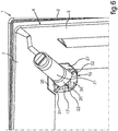
- fig. 5 in a perspective representation the filter device 18 is shown, wherein here according to the explanations as to fig. 4 the cartridge head 20 and thus also the filter cartridge 21 are arranged in a second position and thus in the pivoted position. This second position then also characterizes an exchange position of the filter cartridge 21.
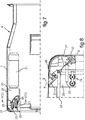
- fig. 7 a side view is shown, in which the filter cartridge 21 and the cartridge head 20 are arranged in the first position.
- fig. 8 a sectional view along the section line VIII-VIII in fig. 7 is shown.
- the lines 17 and 22 are bent just before leading into the rear side of the cartridge head 20 and viewed in the depth direction of the household cooling appliance 1 are oriented towards the front and lead into this cartridge head 20.
- undesired deformations and expansions of the lines 17 and 22, which in particular represent deformable hoses can be avoided when pivoting from the first position into the second position.
- these hoses then are advantageously deformed during this movement in the direction of the arrow P in their neutral fibers.
- Undesired bucklings or reductions in cross section can thereby be avoided.
- undesired predetermined buckling points which could become brittle, can be avoided.
- the filter device 18 comprises a first guiding element 34, which in fig. 7 is shown merely in a broken line and symbolically. With this guiding element the first line 17 can be guided at least in the region where it leads into the cartridge head 20. The above-named advantages for the line 17 are thereby favored once more.
- the filter device 18 has a second guiding element 35, which is shown in fig. 7 equally in a broken line and thus is indicated only symbolically. With this second guiding element 35 the second line 22 can be guided at least in the region where it leads into the cartridge head 20.
- the filter device 18 is for instance also installed on the door 10 and in this regard then is arranged to be correspondingly pivotable relative to the corner portion of the door. It may also be envisaged that in particular the filter cartridge 21 is at least partly covered by a further cover that is not shown.
- the filter device 18 can also be arranged in a further component of the household cooling appliance 1, such as for instance on a drawer or on a door rack.
- the first distances A1 and A2 explained in the advantageous embodiments can be identical or different. Equally also the two distances B1 and B2 can be different. However, they can also be identical.
- first wall 26 of the carrier part 19 and the second wall 27 of the carrier part lead into each other.
- the first wall 26 of the carrier part 19 and the second wall 27 of the carrier part 19 in a preferred embodiment are arranged relative to each at an angle ⁇ of between 85° and 95°.
- the pivot axis B in a preferred embodiment is orientated at a first angle ⁇ 1 smaller than 90° relative to the first wall 26 of the carrier part 19 and at a second angle ⁇ 2 smaller than 90° relative to the second wall 27.
- the pivoting device 29 in a preferred embodiment is configured in such a way that the cartridge head 20 is capable of being positioned in a first position and in a second position that is different therefrom relative to the carrier part 19, wherein the cartridge head 20 in this first position has a distance A1 from the first wall 26 of the carrier part 19 and a first distance A2 from the second wall 27 of the carrier part 19, and the cartridge head 20 in this second position has a second distance B1 from the first wall 26 of the carrier part 19 that is larger than the first distance A1 from the first wall 26 of the carrier part 19, and a second distance B2 from the second wall 27 of the carrier part 19 that is larger than the first distance A2 from the second wall 27 of the carrier part 19.
- the pivoting device 29 in a preferred embodiment is configured in such a way that the cartridge head 20 in a first position and in a second position that is different therefrom is capable of being positioned relative to the carrier part 19, wherein the pivoting device 29 has a holding unit, with which the cartridge head 20 is held fixed in a first position and in a second position.
- the filter device 18 in a preferred embodiment comprises the filter cartridge 21, and the filter cartridge 21 is arranged in a non-destructively releasable way on the cartridge head 20 and in the arranged state is motion-coupled with the cartridge head 20.
- a raised base 31 is formed, wherein the cartridge head 20 is arranged pivotably on this base 31.
- a raised base 31 is formed, wherein the cartridge head 20 is arranged to be pivotable on this base 31.
- the filter device 18 in a preferred embodiment comprises a first liquid line 17, which leads into the cartridge head 20, and preferably comprises a second liquid line that leads into the cartridge head 20.
- the filter device 18 in a preferred embodiment has a first guiding element 34, with which the first line 17 is guided at least in the portion where it leads into the cartridge head 20.
- the filter device 18 in a preferred embodiment comprises a second guiding element 35, with which the second line 22 is guided at least in the region where it leads into the cartridge head 20.
- List of References 1 household cooling appliance 21 filter cartridge 2 housing 22 line 3 receiving space 23 container 4 inner container 24 line 5 bottom wall 25 ice preparator 6 rear wall 26 first wall 7 ceiling wall 26a inner side 8 side wall 27 second wall 9 side wall 27a inner side 10 door 28 corner portion 11 beverage and/or ice dispenser unit 29 pivoting device 30 rear wall 12 dispenser unit 31 first base 13 front side 32 second base 14 niche 33 jacket wall 15 water network 34 first guiding element 16 system 35 second guiding element 17 line B pivot axis 18 filter device C longitudinal axis 19 carrier part P arrow 20 cartridge head ⁇ 1 first angle ⁇ 2 second angle A1 first distance A2 first distance B1 second distance B2 second distance
Landscapes
- Engineering & Computer Science (AREA)
- Chemical & Material Sciences (AREA)
- Physics & Mathematics (AREA)
- Mechanical Engineering (AREA)
- Thermal Sciences (AREA)
- General Engineering & Computer Science (AREA)
- Combustion & Propulsion (AREA)
- Chemical Kinetics & Catalysis (AREA)
- Devices That Are Associated With Refrigeration Equipment (AREA)
- Devices For Dispensing Beverages (AREA)
Abstract
Description
- The invention relates to filter devices for a beverage and/or ice dispenser unit of a household cooling appliance. The invention also relates to a household cooling appliance with a filter device for a beverage and/or ice dispenser unit of this household cooling appliance.
- In the case of a household cooling appliance for storing food it is known that these commonly comprise a receiving space for food, which for instance can be a cooling compartment. A household cooling appliance can also comprise a so-called dispenser unit, which represents a beverage and/or ice dispenser unit. By such a unit a beverage can be generated and/or ice form elements can be generated, which then can be dispensed via an outlet on the household cooling appliance. Commonly such a household cooling appliance then is connected with an external water network, via which the water is supplied to the household cooling appliance. This water then is supplied via a line system to the household cooling appliance of the beverage and/or ice dispenser unit, wherein then this water is used for generating the ice form elements or is used as an extra to the beverage to be generated.
- In this connection it is also known that in the household cooling appliance a filter device is arranged, through which the externally supplied water flows and accordingly is then also filtered. Such a filter device thus is a component, which also requires corresponding space. It comprises a filter cartridge that needs to be exchanged from time to time.
- From the
US 7 056 435 B2 a household cooling appliance is known, which comprises a corresponding filter device. The filter device is arranged on a ceiling of the household cooling appliance. This filter device is designed to be so complex and has an envelope, which is jaw-shaped and thus can be opened and shut as jaw. In this envelope the filter cartridge is arranged. In the opened state the filter cartridge can then be taken out. In this known filter device the arrangement is such that for opening the envelope same, however, can only be pivoted about a horizontal axis. Thereby accessibility is rendered more difficult and on the other hand the filter device needs to be positioned within the household cooling appliance in such a way that accessibility of the filter cartridge is facilitated, which in the case of the only provided option for opening the envelope leads to it that the filter device needs to be positioned relatively freely accessible and spaced far from the lateral walls of the household cooling appliance. - It is the task of the present invention to generate a filter device for a beverage and/or ice dispenser unit of a household cooling appliance, in which its arrangement within the household cooling appliance is facilitated to require little space whilst the exchange of a filter cartridge can still be performed in a simple and user-friendly way. Equally the task is to provide a household cooling appliance with a filter device.
- This task is solved by filter devices and household cooling appliances according to the independent claims.
- An aspect of the invention relates to a filter device for a beverage and/or ice dispenser unit of the household cooling appliance, wherein the filter device is configured for filtering liquid. The filter device has a carrier part for attaching the filter device to a component of the household cooling appliance. The carrier part comprises a first wall. The first wall is configured in particular to be in contact with a first wall of the component of the household cooling appliance. The carrier part comprises a second wall. The second wall is in particular configured to be in contact with a second wall of the component of the household cooling appliance. The first wall of the carrier part and the second wall of the carrier part are arranged to be inclined towards each other. The filter device comprises a cartridge head, which is configured to receive a filter cartridge. The filter device comprises a pivoting device, by which the cartridge head is arranged on the carrier part to be pivotable about a pivot axis.
- The pivot axis extends diagonally between the first wall and the second wall of the carrier part.
- A further aspect of the invention relates to a filter device for a beverage and/or ice dispenser unit of a household cooling appliance, wherein the filter device is configured for filtering liquid. The filtering device comprises a carrier part for attaching the filter device to a component of the household cooling appliance. The carrier part comprises a first wall. The first wall is configured in particular to be in contact with a first wall of the component of the household cooling appliance. The carrier part comprises a second wall. The second wall is configured in particular to be in contact with a second wall of the component of the household cooling appliance. The first wall of the carrier part and the second wall of the carrier part are arranged to be inclined towards each other. The filter device comprises a cartridge head, which is configured for receiving a filter cartridge. The filter device comprises a pivoting device, by which the cartridge head is arranged on the carrier part to be pivotable about a pivot axis. The pivot axis is orientated at a first angle smaller than 90° relative to the first wall of the carrier part and at a second angle smaller than 90° relative to the second wall.
- A further aspect of the invention relates to a filter device for a beverage and/or ice dispenser unit of a household cooling appliance, wherein the filter device is configured for filtering liquid. The filter device comprises a carrier part for attaching the filter device to a component of the household cooling appliance. The carrier part has a first wall. The first wall is in particular configured to be in contact with a first wall of the component of the household cooling appliance. The carrier part has a second wall. The second wall is configured in particular to be in contact with a second wall of the component of the household cooling appliance. The first wall of the carrier part and the second wall of the carrier part are arranged to be inclined towards each other. The filter device comprises a cartridge head, which is configured to receive a filter cartridge. The filter device comprises a pivoting device, by which the cartridge head is arranged to be pivotable about a pivot axis. The pivoting device is configured in such a way that the cartridge head is capable of being positioned in a first position relative to the carrier part and in a second position relative to the carrier part that is different therefrom. The cartridge head in this first position has a first distance from the first wall of the carrier part and has a first distance from the second wall of the carrier part. The cartridge head in this second position has a second distance from the first wall of the carrier part that is larger in comparison with the first distance from the first wall of the carrier part, and in this second position has a second distance from the second wall of the carrier part that is larger than the first distance from the second wall of the carrier part.
- A further aspect of the invention relates to a household cooling appliance, which comprises a housing, in which a receiving space for food is formed. The household cooling appliance has an inner container having walls, wherein by the walls of the inner container the receiving space is bounded. By two walls of the inner container that lead into each other a corner portion is formed. The household cooling appliance comprises a beverage and/or ice dispenser unit, which is configured for dispensing a beverage and/or ice form elements. Such a unit is also referred to as dispenser unit. The beverage and/or ice dispenser unit is also configured to generate the beverage and/or the ice form elements. The household cooling appliance has a filter device, which is configured for filtering a liquid. The filtered liquid is capable of being supplied to the beverage and/or ice dispenser unit for generating the beverage and/or ice form elements. The filter device comprises a cartridge head, which is configured for receiving a filter cartridge. The cartridge head is arranged to be pivotable about a pivot axis of the filter device. The filter device is arranged in this corner portion formed by the walls. The pivot axis is diagonally arranged between these walls forming this corner portion.
- A further aspect of the invention relates to a household cooling appliance, which comprises a housing, in which a receiving space for food is formed. The household cooling appliance has an inner container, which comprises walls, wherein by the walls of the inner container the receiving space is bounded. By two walls of the inner container that lead into each other a corner portion is formed. The household cooling appliance has a beverage and/or ice dispenser unit, which is configured for dispensing a beverage and/or ice form elements. Such a unit is also referred to as dispenser unit. The beverage and/or ice dispenser unit is also configured for generating the beverage and/or the ice form elements. The household cooling appliance comprises a filter device, which is configured for filtering a liquid. The filtered liquid is capable of being supplied to the beverage and/or ice dispenser unit for generating the beverage and/or the ice form elements. The filter device comprises a carrier part for attaching the filter device to a component of the household cooling appliance. The carrier part has a first wall. The first wall is in particular configured to be in contact with a first wall of the component of the household cooling appliance. The carrier part has a second wall. The second wall is configured in particular to be in contact with a second wall of the component of the household cooling appliance. The first wall of the carrier part and the second wall of the carrier part are arranged to be inclined towards each other. The filter device comprises a cartridge head, which is configured for receiving a filter cartridge. The filter device has a pivoting device, by which the cartridge head is arranged on the carrier part to be pivotable about a pivot axis. The pivot axis extends diagonally between the first wall and the second wall of the carrier part.
- A further aspect of the invention relates to a household cooling appliance, which comprises a housing, in which a receiving space for food is formed. The household cooling appliance comprises an inner container, which has walls, wherein by the walls of the inner container the receiving space is bounded. By two walls of the inner container that lead into each other a corner portion is formed. The household cooling appliance has a beverage and/or ice dispenser unit, which is configured for dispensing a beverage and/or ice form elements. Such unit is also referred to as dispenser unit. The beverage and/or ice dispenser unit is also configured for generating a beverage and/or the ice form elements. The household cooling appliance comprises a filter device, which is configured for filtering a liquid. The filtered liquid is capable of being supplied to the beverage and/or ice dispenser unit for generating the beverage and/or the ice form element. The filter device has a carrier part for attaching the filter device to a component of the household cooling appliance. The carrier part has a first wall. The first wall is in particular configured to be in contact with a first wall of the component of the household cooling appliance. The carrier part has a second wall. The second wall is configured in particular to be in contact with a second wall of the component of the household cooling appliance. The first wall of the carrier part and the second wall of the carrier part are arranged to be inclined towards each other. The filter device comprises a cartridge head, which is configured for receiving a filter cartridge. The filter cartridge comprises a pivoting device, by which the cartridge head is arranged on the carrier part to be pivotable about a pivot axis. The pivot axis is orientated at a first angle smaller than 90° relative to the first wall of the carrier part and at a second angle smaller than 90° relative to the second wall.
- A further aspect of the invention relates to a household cooling appliance, which comprises a housing, in which a receiving space for food is formed. The household cooling appliance comprises an inner container, which has walls, wherein by the walls of the inner container the receiving space is bounded. By two walls of the inner container leading into each other a corner portion is formed. The household cooling appliance has a beverage and/or ice dispenser unit, which is configured for dispensing a beverage and/or ice form elements. Such a unit is also referred to as dispenser unit. The beverage and/or ice dispenser unit is also configured for generating the beverage and/or the ice form elements. The household cooling appliance comprises a filter device, which is configured for filtering a liquid. The filtered liquid is capable of being supplied to the beverage and/or ice dispenser unit for generating the beverage and/or the ice form elements. The filter device comprises a carrier part for attaching the filter device to a component of the household cooling appliance. The carrier part has a first wall. The first wall is in particular configured to be in contact with a first wall of the component of the household cooling appliance. The carrier part has a second wall. The second wall is in particular configured to be in contact with a second wall of the component of the household cooling appliance. The first wall of the carrier part and the second wall of the carrier part are configured to be inclined towards each other. The filter device comprises a cartridge head, which is configured for receiving a filter cartridge. The filter device comprises a pivoting device, by which the cartridge head is arranged to be pivotable about a pivot axis on the carrier part. The pivoting device is configured in such a way that the cartridge head is capable of being positioned in a first position relative to the carrier part and in a second position relative to the carrier part that is different therefrom. The cartridge head in this first position has a first distance from the first wall of the carrier part and has a first distance from the second wall of the carrier part. The cartridge head in this second position has a second distance from the first wall of the carrier part that is larger in comparison with the first distance from the first wall of the carrier part, and in this second position has a second distance from the second wall of the carrier part that is than the first distance from the second wall of the carrier part.
- By these aspects of the invention the arrangement of the filter device within the household cooling appliance is facilitated in a space-saving way and the exchange of a filter cartridge can be performed in a simple and user-friendly manner.
- By the indications "top", "bottom", "front", "rear", "horizontal", "vertical", "depth direction", "width direction", "height direction" etc. the positions and orientations for an intended use and intended arrangement of the ice preparator bowl or the device are indicated.
- Further features of the invention derive from the claims, the figures, and the description of the figures. The features and feature combinations previously mentioned in the description as well as the features and feature combinations named in the following in the description of the figures and/or shown in the figures alone can be used not only in the respectively indicated combination, but also in any other combination, without leaving the scope of the invention. Thus also embodiments are to be considered as comprised or disclosed by the invention, which are not explicitly shown and explained in the figures, however, derive through separated feature combinations from the explained embodiments and are generable therefrom. Also embodiments and feature combinations are to be considered as being disclosed, which thus do not comprise all features of an originally formulated independent claim. Moreover, embodiments and feature combinations are to be considered as being disclosed, in particular by the above set out embodiments, which go beyond the feature combinations set out in the back-references of the claims or deviate from them.
- Embodiments of the invention are explained in more detail in the following by reference to the schematic drawings. These show in:
- fig. 1
- a schematic sectional view of an embodiment of a household cooling appliance;
- fig. 2
- a schematic front view of the household cooling appliance according to
fig. 1 ; - fig. 3
- an enlarged view of a partial portion in
fig. 2 , in which a cartridge head and a filter cartridge are shown in a first position; - fig. 4
- an enlarged representation of a partial portion in
fig. 2 , in which a cartridge head and a filter cartridge are shown in a second position; - fig. 5
- a perspective view of the components in
fig. 4 ; - fig. 6
- a perspective view of the components in
fig. 3 ; - fig. 7
- a lateral view of the components according to
fig. 3 andfig. 6 ; and - fig. 8
- a sectional view of the presentation in
fig. 7 in a front view. - In the figures identical or functionally identical elements are equipped with the same reference signs.
- In
fig. 1 in a simplified schematic sectional view ahousehold cooling appliance 1 is shown, which is configured for storing and preserving food. Thehousehold cooling appliance 1 comprises ahousing 2, in which at least one receivingspace 3 for food is configured. This receivingspace 3 is preferably a cooling compartment. Thehousehold cooling appliance 1 moreover can also have one further receiving space, which can for instance be a freezer compartment. - The
household cooling appliance 1 has aninner container 4, which by walls bounds the receivingspace 3. Infig. 1 abottom wall 5, arear wall 6, and aceiling wall 7 is shown. Moreover aside wall 8 and a side wall 9 (fig. 2 ) is to be allocated with theinner container 4. - The
inner container 4 is arranged within thehousing 2. - The
household cooling appliance 1 moreover comprises adoor 10, which is arranged for front side closure of the receivingspace 3. Thedoor 10 is in particular arranged on thehousing 2, in particular arranged to be pivotable. A pivot axis A is orientated in the height direction and thus in the y direction of thehousehold cooling appliance 1. - The
household cooling appliance 1 in an advantageous embodiment comprises a dispenser unit, which is a beverage and/orice dispenser unit 11. This beverage and/or ice dispenser unit is configured for dispensing a beverage and/or ice form elements, such as ice cubes or crushed ice. This also means that the beverage and/orice dispenser unit 11 is configured for generating the beverage and/or the ice form elements. The beverage and/orice dispenser unit 11 comprises adispenser unit 12, via which the beverage and/or the ice form elements can be dispensed. For this purpose on thefront side 13 of the door 10 aniche 14 is configured, into which a receiving vessel can be inserted, into which then the dispensed beverage and/or the ice form elements can be inserted. Thisniche 14 is accessible on the front side and the beverage and/or the ice form elements can also be dispensed with thedoor 10 being closed. - The
household cooling appliance 1 is connected to anexternal water network 15. Thehousehold cooling appliance 1 has a water-conductingsystem 16, to which a multitude of functional units and lines belong and by means of which the water supplied by thewater network 15 is conducted and processed within thehousehold cooling appliance 1, in order to then be able to be made available to the beverage and/orice dispenser unit 11. - The
line 17 coming in particular directly from thewater network 15 leads to afilter device 18 of thehousehold cooling appliance 1. With thefilter device 18 the water supplied from thewater network 15 is filtered, in order to be able to then be provided after the filtering for the generation of the ice form elements and/or for instance also to be conducted into a container, in which then the filtered water is provided for the generation also of a beverage. - The
filter device 18 in the shown embodiment comprises in particular acarrier part 19. Thefilter device 18 in a further advantageous embodiment comprises acartridge head 20. Thecartridge head 20 is arranged on thecarrier part 19 to be capable of being moved. - In the shown embodiment moreover a
filter cartridge 21 is shown, which is inserted into the cartridge head. For instance this attachment can be configured by a bayonet joint. In the state, in which thefilter cartridge 21 is mounted on thecartridge head 20, thefilter cartridge 21 is motion-coupled with thiscartridge head 20. - The
filter cartridge 21 is arranged to be non-destructively releasable on thecartridge head 20 so that it also can be exchanged. - The
line 17 directly leads into thecartridge head 20. Thisline 17 is an inlet hose, which conducts the water from thewater network 15 to thefilter cartridge 21. Moreover, afurther line 22 is shown, which leads from thecartridge head 20 to acontainer 23 of the water-conductingsystem 16. The water filtered through thefilter cartridge 21 is conducted from thefilter device 18 via thisline 22 to thiscontainer 23. - From there it can then be supplied via a
further line 24 to anice preparator 25, which in particular is integral part of the beverage and/orice dispenser unit 11, wherein in theice preparator 25 then the ice form elements are generated. - In an advantageous embodiment the
carrier part 19 is configured as attachment part. With thiscarrier part 19 theentire filter device 18 can be arranged on a component of thehousehold cooling appliance 1. Such component of thehousehold cooling appliance 1 can be at least one wall of theinner container 4. Preferably thecarrier part 19 is configured such that thefilter device 8 can be attached on at least two different walls of theinner container 4 or is arranged to be at least in contact with each of them. - The
carrier part 19, as this is shown in the schematic front view of thehousehold cooling appliance 1 according tofig. 2 , can comprise two walls, namely afirst wall 26 and asecond wall 27. In particular in an advantageous embodiment of these twowalls walls carrier part 19 lead into each other, as this is shown infig. 2 in an exemplary embodiment. Thewalls inner container 4. - In particularly advantageous way the
filter device 18 is arranged in acorner portion 28 in the receivingspace 3. In particular this positioning of thefilter device 18 is arranged in atop corner portion 28. In the shown advantageous embodiment thecorner portion 28 in the case of this front view of thehousehold cooling appliance 1 the right top corner portion is shown, which is advantageous in particular, if thedoor 10 relative thereto is arranged on thehousing 2 to be pivotable towards the left side. By such a positioning of thefilter device 18 same can be arranged within the receivingspace 3 in a very space-saving way and then is positioned to be least interfering with respect thereto. - The
filter device 18 further has apivoting device 29. By means of thispivoting device 29 thecartridge head 20 is pivotable relative to thecarrier part 19, wherein thecartridge head 20 is arranged on thiscarrier part 19. A pivot axis B of thispivoting device 29 in an advantageous embodiment is arranged diagonally between thefirst wall 26 and thesecond wall 27. This pivot axis B thus extends diagonally between thesewalls carrier part 19. - In the embodiment in
fig. 2 this also means that this pivot axis B is orientated not to be in parallel to a space direction of thehousehold cooling appliance 1 and thus not in parallel to the height direction and also not in parallel to the width direction (x direction). By such an arrangement thecartridge head 20 with thefilter cartridge 21 can be pivoted in a direction that is represented by the arrow P. This means that quasi a slanted pivoting of thiscartridge head 20 from top diagonally towards the bottom in the receivingspace 3 is performed. - By such a design on the one hand the
filter device 18 can be positioned in a first position, in which thecartridge head 20 is arranged in an operation position, in a very space-saving position maximally approaching the two walls, which are inclined towards each other, in particular thewalls inner container 4, on the other hand then in the pivoted state, in which a second position of thecartridge head 20 and thus also thefilter cartridge 21 has been assumed, a very user-friendly and comprehensive accessibility of thefilter cartridge 21 can be achieved. Thefilter cartridge 21 in this second position can then be grasped by a hand of a user in order to be able to achieve a simple handling in this regard by a rotational movement, which in particular is required for releasing a bayonet locking. - In
fig. 3 an enlarged presentation of the partial portion of thehousehold cooling appliance 1 is shown, in which thefiltering device 18 is arranged. Infig. 3 in this connection the first position is shown, which is also an operating position. As can be seen infig. 3 , the twowalls carrier part 19 are in large-area contact with theceiling wall 7 and theside wall 8 of theinner container 4 as contact walls and support walls. - Preferably it may be envisaged that the
carrier part 19 comprises afurther wall 30, which represents a rear wall. In particular it is advantageous, if thisrear wall 30 is in contact with therear wall 6 of theinner container 4. Thisrear wall 30 of thecarrier part 19 leads into thefirst wall 26 and thesecond wall 27. By these threewalls carrier part 19, in which thecartridge head 20 is received. Thereby same is also arranged to be protected. Thecarrier part 19 by such a design with the named walls and their positioning relative to each other also mechanically is very stable and thus in particular also torsion-resistant. Thereby it can also receive thecartridge head 20 with thefilter cartridge 21 in a stable way and also when moving thecartridge head 20 with thefilter cartridge 21 no undesired deformations of thecarrier part 19 occur. - As moreover can be discerned in
fig. 3 , thecarrier part 19 in an advantageous embodiment on aninterior side 26a comprises a raisedbase 31. Thisbase 31 represents a coupling dome for thecartridge head 20, which thus then is mounted rotatably spaced from the twowalls base 31. - In particular it is envisaged that also on the
second wall 27 a raisedbase 32 is formed, which is designed to be functionally corresponding to thefirst base 31. Also this second raisedbase 32 is configured on aninner side 27a of thesecond wall 27 of thecarrier part 19. In particular thesebases walls - Preferably the
carrier part 19 is configured to be integrally formed and in particular a plastic part. - In an advantageous embodiment the pivot axis B is orientated in such a way that it is arranged at a first angle α1 relative to the
first wall 26, wherein this angle α1 is smaller 90°, in particular between 35° and 55°, in particular between 40° and 50°, preferably 45°. - In an advantageous embodiment moreover it is envisaged that the pivot axis B is arranged at a second angle α2, which is in particular smaller than 90°, relative to the
second wall 27. Here, too, this second angle α2 preferably amounts to between 35° and 55°, in particular between 40° and 50°, preferably 45°. - Such orientation of the pivot axis B can also be configured independently of the
first wall 26 and thesecond wall 27 with respect to the walls of theinner container 4, for instance relative to theceiling wall 7 and to avertical side wall 8. This can then be the case, if thecarrier part 19 does not comprise thefirst wall 26 and/or thesecond wall 27. - For instance in such a design it may be envisaged that the
carrier part 19 for instance only comprises arear wall 19, on which then for instance thebases cartridge head 20 is arranged correspondingly to be mounted pivotably. - In a further advantageous embodiment it is envisaged that the
cartridge head 20 and thus then also afilter cartridge 21 arranged thereon in this position shown infig. 3 is arranged at a first distance A1 from a first wall, in particular theceiling wall 7, of theinner container 4. In particular in this first position thecartridge head 20 and thus then also thefilter cartridge 21 is arranged at a first distance A2 from a further different wall, in particular thevertical side wall 8 of theinner container 4. - The pivoting
device 29 is then preferably configured to have in the second position shown infig. 4 , in which thecartridge head 20 with thefilter cartridge 21 has been pivoted in the direction of the arrow P, a respectively larger distance. This means, as it is shown infig. 4 , that in this second position thefilter cartridge 21 has a second distance B1 from thefirst wall 26, wherein this second distance B1 is larger than the first distance A1. At the same time in this second position then also a second distance B2 from thesecond wall 27 is configured, which is larger than the first distance A2 from thevertical side wall 8 in the first position according tofig. 3 . In this second position according to the representation infig. 4 then thefilter cartridge 21 at itsjacket wall 33 can be easily gripped with a hand by a user and with a pivot movement be moved about a longitudinal axis C of thefilter cartridge 21 locally relative to thecartridge head 20 and thus be released from thecartridge head 20. - Generally it is also possible in a further embodiment that the
filter device 18 comprises nocarrier part 19. In such an embodiment it could be envisaged that thecartridge head 20 is arranged to be directly pivotable on theinner container 4. For instance then correspondingbases inner container 4, for instance on theceiling wall 7 and thevertical side wall 8 and thecartridge head 20 be pivotably mounted thereon as component that is separate therefrom. Also in the case of such an embodiment in an advantageous way the pivot axis B then would be correspondingly orientated as it is envisaged in the representations according tofig. 2 to fig. 4 . - In
fig. 5 in a perspective representation thefilter device 18 is shown, wherein here according to the explanations as tofig. 4 thecartridge head 20 and thus also thefilter cartridge 21 are arranged in a second position and thus in the pivoted position. This second position then also characterizes an exchange position of thefilter cartridge 21. - In
fig. 6 in a perspective representation of thecartridge head 20 and thefilter cartridge 21 is shown in a first position, as it has already been explained infig. 3 . - In
fig. 7 a side view is shown, in which thefilter cartridge 21 and thecartridge head 20 are arranged in the first position. - In
fig. 8 a sectional view along the section line VIII-VIII infig. 7 is shown. Here it can also be discerned how thelines cartridge head 20 and viewed in the depth direction of thehousehold cooling appliance 1 are oriented towards the front and lead into thiscartridge head 20. By such an orientation and by such an immediate vicinity of the portions of thelines cartridge head 20 relative to the pivot axis B undesired deformations and expansions of thelines - In an advantageous embodiment it may also be envisaged that the
filter device 18 comprises afirst guiding element 34, which infig. 7 is shown merely in a broken line and symbolically. With this guiding element thefirst line 17 can be guided at least in the region where it leads into thecartridge head 20. The above-named advantages for theline 17 are thereby favored once more. In an advantageous embodiment it may also be envisaged that thefilter device 18 has asecond guiding element 35, which is shown infig. 7 equally in a broken line and thus is indicated only symbolically. With this second guidingelement 35 thesecond line 22 can be guided at least in the region where it leads into thecartridge head 20. By this arrangement of thelines cartridge head 20 in the area of the pivot axis B also minimized bending loads for theselines filter device 18 is for instance also installed on thedoor 10 and in this regard then is arranged to be correspondingly pivotable relative to the corner portion of the door. It may also be envisaged that in particular thefilter cartridge 21 is at least partly covered by a further cover that is not shown. Thefilter device 18 can also be arranged in a further component of thehousehold cooling appliance 1, such as for instance on a drawer or on a door rack. - The first distances A1 and A2 explained in the advantageous embodiments can be identical or different. Equally also the two distances B1 and B2 can be different. However, they can also be identical.
- Preferably it may generally be envisaged that the
first wall 26 of thecarrier part 19 and thesecond wall 27 of the carrier part lead into each other. Thefirst wall 26 of thecarrier part 19 and thesecond wall 27 of thecarrier part 19 in a preferred embodiment are arranged relative to each at an angle β of between 85° and 95°. The pivot axis B in a preferred embodiment is orientated at a first angle α1 smaller than 90° relative to thefirst wall 26 of thecarrier part 19 and at a second angle α2 smaller than 90° relative to thesecond wall 27. In particular the pivotingdevice 29 in a preferred embodiment is configured in such a way that thecartridge head 20 is capable of being positioned in a first position and in a second position that is different therefrom relative to thecarrier part 19, wherein thecartridge head 20 in this first position has a distance A1 from thefirst wall 26 of thecarrier part 19 and a first distance A2 from thesecond wall 27 of thecarrier part 19, and thecartridge head 20 in this second position has a second distance B1 from thefirst wall 26 of thecarrier part 19 that is larger than the first distance A1 from thefirst wall 26 of thecarrier part 19, and a second distance B2 from thesecond wall 27 of thecarrier part 19 that is larger than the first distance A2 from thesecond wall 27 of thecarrier part 19. - The pivoting
device 29 in a preferred embodiment is configured in such a way that thecartridge head 20 in a first position and in a second position that is different therefrom is capable of being positioned relative to thecarrier part 19, wherein the pivotingdevice 29 has a holding unit, with which thecartridge head 20 is held fixed in a first position and in a second position. - The
filter device 18 in a preferred embodiment comprises thefilter cartridge 21, and thefilter cartridge 21 is arranged in a non-destructively releasable way on thecartridge head 20 and in the arranged state is motion-coupled with thecartridge head 20. - On an
inner side 26a of thefirst wall 26 of thecarrier part 19 in a preferred embodiment a raisedbase 31 is formed, wherein thecartridge head 20 is arranged pivotably on thisbase 31. - On an
inner side 27a of thesecond wall 27 of thecarrier part 19 in a preferred embodiment a raisedbase 31 is formed, wherein thecartridge head 20 is arranged to be pivotable on thisbase 31. - The
filter device 18 in a preferred embodiment comprises a firstliquid line 17, which leads into thecartridge head 20, and preferably comprises a second liquid line that leads into thecartridge head 20. - The
filter device 18 in a preferred embodiment has afirst guiding element 34, with which thefirst line 17 is guided at least in the portion where it leads into thecartridge head 20. - The
filter device 18 in a preferred embodiment comprises asecond guiding element 35, with which thesecond line 22 is guided at least in the region where it leads into thecartridge head 20.List of References 1 household cooling appliance 21 filter cartridge 2 housing 22 line 3 receiving space 23 container 4 inner container 24 line 5 bottom wall 25 ice preparator 6 rear wall 26 first wall 7 ceiling wall 26a inner side 8 side wall 27 second wall 9 side wall 27a inner side 10 door 28 corner portion 11 beverage and/or ice dispenser unit 29 pivoting device 30 rear wall 12 dispenser unit 31 first base 13 front side 32 second base 14 niche 33 jacket wall 15 water network 34 first guiding element 16 system 35 second guiding element 17 line B pivot axis 18 filter device C longitudinal axis 19 carrier part P arrow 20 cartridge head α1 first angle α2 second angle A1 first distance A2 first distance B1 second distance B2 second distance
Claims (17)
the cartridge head (20) in this first position has a first distance (A1) from the first wall (26) of the carrier part (19) and a first distance (A2) from the second wall (27) of the carrier part (19), and
the cartridge head (20) in this second position has a second distance (B1) that is larger in comparison with the first distance (A1) from the first wall (26) of the carrier part (19), and a second distance (B2) from the second wall (27) of the carrier part (19) that is larger than the first distance (A2) from the second wall (27) of the carrier part (19).
Priority Applications (1)
| Application Number | Priority Date | Filing Date | Title |
|---|---|---|---|
| PL18159403T PL3370023T3 (en) | 2017-03-02 | 2018-03-01 | Filter device for a beverage and/or ice dispenser unit of a household cooling appliance |
Applications Claiming Priority (1)
| Application Number | Priority Date | Filing Date | Title |
|---|---|---|---|
| US15/447,883 US10252198B2 (en) | 2017-03-02 | 2017-03-02 | Filter device for a beverage and/or ice dispenser unit of a household cooling appliance and household appliance having a filter device |
Publications (2)
| Publication Number | Publication Date |
|---|---|
| EP3370023A1 true EP3370023A1 (en) | 2018-09-05 |
| EP3370023B1 EP3370023B1 (en) | 2020-05-13 |
Family
ID=61526723
Family Applications (1)
| Application Number | Title | Priority Date | Filing Date |
|---|---|---|---|
| EP18159403.7A Active EP3370023B1 (en) | 2017-03-02 | 2018-03-01 | Filter device for a beverage and/or ice dispenser unit of a household cooling appliance |
Country Status (4)
| Country | Link |
|---|---|
| US (1) | US10252198B2 (en) |
| EP (1) | EP3370023B1 (en) |
| CN (1) | CN108525386B (en) |
| PL (1) | PL3370023T3 (en) |
Families Citing this family (8)
| Publication number | Priority date | Publication date | Assignee | Title |
|---|---|---|---|---|
| US12123638B2 (en) | 2022-09-30 | 2024-10-22 | Whirlpool Corporation | Refrigerator appliance |
| USD1072175S1 (en) | 2023-03-17 | 2025-04-22 | Haier Us Appliance Solutions, Inc. | Water filter |
| USD1072177S1 (en) | 2023-03-17 | 2025-04-22 | Haier Us Appliance Solutions, Inc. | Water filter |
| USD1072178S1 (en) | 2023-03-17 | 2025-04-22 | Haier Us Appliance Solutions, Inc. | Water filter |
| USD1072171S1 (en) | 2023-03-17 | 2025-04-22 | Haier Us Appliance Solutions, Inc. | Water filter |
| USD1072176S1 (en) | 2023-03-17 | 2025-04-22 | Haier Us Appliance Solutions, Inc. | Water filter |
| USD1072174S1 (en) | 2023-03-17 | 2025-04-22 | Haier Us Appliance Solutions, Inc. | Water filter |
| USD1072172S1 (en) | 2023-03-17 | 2025-04-22 | Haier Us Appliance Solutions, Inc. | Water filter |
Citations (3)
| Publication number | Priority date | Publication date | Assignee | Title |
|---|---|---|---|---|
| WO2003008883A1 (en) * | 2001-07-16 | 2003-01-30 | Maytag Corporation | Hinge down refrigerator water filter |
| WO2005073124A2 (en) * | 2004-01-20 | 2005-08-11 | 3M Innovative Properties Company | Water dispenser with water filter for a refrigerator |
| WO2009062912A2 (en) * | 2007-11-12 | 2009-05-22 | BSH Bosch und Siemens Hausgeräte GmbH | Water filter device for an electric refrigerator |
Family Cites Families (14)
| Publication number | Priority date | Publication date | Assignee | Title |
|---|---|---|---|---|
| US6564569B1 (en) * | 2000-09-22 | 2003-05-20 | Brian D. Havens | Refrigeration system for commercial food handling |
| CN100498163C (en) * | 2003-05-16 | 2009-06-10 | 乐金电子(天津)电器有限公司 | Water purifier for refrigerator and refrigerator utilizing the water purifier |
| KR100596527B1 (en) * | 2004-10-25 | 2006-07-06 | 삼성전자주식회사 | Refrigerator |
| DE102006050302B4 (en) * | 2006-10-23 | 2017-05-24 | Aquis Wasser-Luft-Systeme Gmbh, Lindau, Zweigniederlassung Rebstein | Tank, filter cartridge and device with tank |
| CN101231078A (en) * | 2007-01-24 | 2008-07-30 | 泰州乐金电子冷机有限公司 | Installation structure for water purifier of refrigerator |
| JP2010096410A (en) * | 2008-10-16 | 2010-04-30 | Sharp Corp | Refrigerator |
| CN102109266A (en) * | 2009-12-25 | 2011-06-29 | 海尔集团公司 | Refrigerator |
| CN101865588A (en) * | 2010-07-13 | 2010-10-20 | 合肥美的荣事达电冰箱有限公司 | Refrigerator |
| KR101713327B1 (en) * | 2010-07-14 | 2017-03-08 | 엘지전자 주식회사 | Refirgerator |
| CN102338523A (en) * | 2011-08-16 | 2012-02-01 | 合肥美的荣事达电冰箱有限公司 | Door type manual ice maker and refrigerator with same |
| EP2613112B1 (en) * | 2012-01-03 | 2019-10-30 | LG Electronics, Inc. | Refrigerator having storage container |
| KR101601391B1 (en) * | 2014-02-12 | 2016-03-08 | 엘지전자 주식회사 | Refrigerator and water purification apparatus for the refrigerator |
| US9688546B2 (en) * | 2014-09-16 | 2017-06-27 | Haier Us Appliance Solutions, Inc. | Electrical connection for an appliance water filter |
| CN105521652B (en) * | 2015-12-25 | 2018-10-23 | 魏斯瓦瑟环境技术(嘉兴)有限公司 | A kind of water purifier |
-
2017
- 2017-03-02 US US15/447,883 patent/US10252198B2/en active Active
-
2018
- 2018-02-28 CN CN201810165723.5A patent/CN108525386B/en not_active Expired - Fee Related
- 2018-03-01 EP EP18159403.7A patent/EP3370023B1/en active Active
- 2018-03-01 PL PL18159403T patent/PL3370023T3/en unknown
Patent Citations (4)
| Publication number | Priority date | Publication date | Assignee | Title |
|---|---|---|---|---|
| WO2003008883A1 (en) * | 2001-07-16 | 2003-01-30 | Maytag Corporation | Hinge down refrigerator water filter |
| US7056435B2 (en) | 2001-07-16 | 2006-06-06 | Maytag Corporation | Hinge down refrigerator water filter |
| WO2005073124A2 (en) * | 2004-01-20 | 2005-08-11 | 3M Innovative Properties Company | Water dispenser with water filter for a refrigerator |
| WO2009062912A2 (en) * | 2007-11-12 | 2009-05-22 | BSH Bosch und Siemens Hausgeräte GmbH | Water filter device for an electric refrigerator |
Also Published As
| Publication number | Publication date |
|---|---|
| CN108525386A (en) | 2018-09-14 |
| US10252198B2 (en) | 2019-04-09 |
| US20180250618A1 (en) | 2018-09-06 |
| CN108525386B (en) | 2022-06-07 |
| EP3370023B1 (en) | 2020-05-13 |
| PL3370023T3 (en) | 2020-11-16 |
Similar Documents
| Publication | Publication Date | Title |
|---|---|---|
| EP3370023B1 (en) | Filter device for a beverage and/or ice dispenser unit of a household cooling appliance | |
| EP3705017B1 (en) | Supporting device and dish washer having the same | |
| EP2173228B1 (en) | Dish washer provided with a coupling device for coupling between a spray liquid pipe and a spraying arm in a spraying system | |
| US9186036B2 (en) | Dishwasher with detergent dispenser | |
| US9241607B2 (en) | Silverware basket with integral spray jets for a dishwasher | |
| US9861260B2 (en) | Dishwasher appliance and a tine assembly for a dishwasher appliance | |
| AU2009231451B2 (en) | Dishwashing machine | |
| US9161674B2 (en) | Silverware basket with features for assisting removal of the silverware basket from a dishwasher appliance | |
| JP4913829B2 (en) | Filter coffee machine | |
| JP2017089100A (en) | Dishwashing sink | |
| US20180206699A1 (en) | Dishwasher | |
| US20200146528A1 (en) | Dishwasher wash basket | |
| CA2581770A1 (en) | Dispenser rinse system for a drawer-type dishwasher | |
| US20130328465A1 (en) | Silverware basket for a dishwasher appliance | |
| CN116600693B (en) | Article holder assembly for dishwasher appliance | |
| US11730339B2 (en) | Article holder assembly for a dishwasher appliance | |
| US12016509B2 (en) | Water feed tube for dishwasher with integrated retainer | |
| US20180094852A1 (en) | Refrigeration appliance apparatus and domestic refrigeration appliance | |
| US12564304B2 (en) | Appliance handle clip for securing an appliance handle in transport | |
| CN102458211A (en) | washing machine | |
| CN111839395A (en) | Dishwasher | |
| EP2331893B1 (en) | Cooling device with rotatable shelf | |
| US8840202B2 (en) | Dishwasher appliance with a contoured silverware basket | |
| KR101819503B1 (en) | Rack of Dishwahser | |
| EP3666155A1 (en) | Dish washer |
Legal Events
| Date | Code | Title | Description |
|---|---|---|---|
| PUAI | Public reference made under article 153(3) epc to a published international application that has entered the european phase |
Free format text: ORIGINAL CODE: 0009012 |
|
| STAA | Information on the status of an ep patent application or granted ep patent |
Free format text: STATUS: THE APPLICATION HAS BEEN PUBLISHED |
|
| AK | Designated contracting states |
Kind code of ref document: A1 Designated state(s): AL AT BE BG CH CY CZ DE DK EE ES FI FR GB GR HR HU IE IS IT LI LT LU LV MC MK MT NL NO PL PT RO RS SE SI SK SM TR |
|
| AX | Request for extension of the european patent |
Extension state: BA ME |
|
| STAA | Information on the status of an ep patent application or granted ep patent |
Free format text: STATUS: REQUEST FOR EXAMINATION WAS MADE |
|
| 17P | Request for examination filed |
Effective date: 20190305 |
|
| RBV | Designated contracting states (corrected) |
Designated state(s): AL AT BE BG CH CY CZ DE DK EE ES FI FR GB GR HR HU IE IS IT LI LT LU LV MC MK MT NL NO PL PT RO RS SE SI SK SM TR |
|
| REG | Reference to a national code |
Ref country code: DE Ref legal event code: R079 Ref document number: 602018004296 Country of ref document: DE Free format text: PREVIOUS MAIN CLASS: F25D0023120000 Ipc: C02F0001000000 |
|
| GRAP | Despatch of communication of intention to grant a patent |
Free format text: ORIGINAL CODE: EPIDOSNIGR1 |
|
| STAA | Information on the status of an ep patent application or granted ep patent |
Free format text: STATUS: GRANT OF PATENT IS INTENDED |
|
| RIC1 | Information provided on ipc code assigned before grant |
Ipc: C02F 1/00 20060101AFI20190911BHEP Ipc: F25D 23/12 20060101ALI20190911BHEP |
|
| INTG | Intention to grant announced |
Effective date: 20190925 |
|
| GRAS | Grant fee paid |
Free format text: ORIGINAL CODE: EPIDOSNIGR3 |
|
| GRAJ | Information related to disapproval of communication of intention to grant by the applicant or resumption of examination proceedings by the epo deleted |
Free format text: ORIGINAL CODE: EPIDOSDIGR1 |
|
| GRAL | Information related to payment of fee for publishing/printing deleted |
Free format text: ORIGINAL CODE: EPIDOSDIGR3 |
|
| STAA | Information on the status of an ep patent application or granted ep patent |
Free format text: STATUS: REQUEST FOR EXAMINATION WAS MADE |
|
| GRAR | Information related to intention to grant a patent recorded |
Free format text: ORIGINAL CODE: EPIDOSNIGR71 |
|
| STAA | Information on the status of an ep patent application or granted ep patent |
Free format text: STATUS: GRANT OF PATENT IS INTENDED |
|
| INTC | Intention to grant announced (deleted) | ||
| INTG | Intention to grant announced |
Effective date: 20200131 |
|
| GRAA | (expected) grant |
Free format text: ORIGINAL CODE: 0009210 |
|
| STAA | Information on the status of an ep patent application or granted ep patent |
Free format text: STATUS: THE PATENT HAS BEEN GRANTED |
|
| AK | Designated contracting states |
Kind code of ref document: B1 Designated state(s): AL AT BE BG CH CY CZ DE DK EE ES FI FR GB GR HR HU IE IS IT LI LT LU LV MC MK MT NL NO PL PT RO RS SE SI SK SM TR |
|
| REG | Reference to a national code |
Ref country code: GB Ref legal event code: FG4D |
|
| REG | Reference to a national code |
Ref country code: CH Ref legal event code: EP |
|
| REG | Reference to a national code |
Ref country code: DE Ref legal event code: R096 Ref document number: 602018004296 Country of ref document: DE |
|
| REG | Reference to a national code |
Ref country code: AT Ref legal event code: REF Ref document number: 1270048 Country of ref document: AT Kind code of ref document: T Effective date: 20200615 |
|
| REG | Reference to a national code |
Ref country code: LT Ref legal event code: MG4D |
|
| REG | Reference to a national code |
Ref country code: NL Ref legal event code: MP Effective date: 20200513 |
|
| PG25 | Lapsed in a contracting state [announced via postgrant information from national office to epo] |
Ref country code: SE Free format text: LAPSE BECAUSE OF FAILURE TO SUBMIT A TRANSLATION OF THE DESCRIPTION OR TO PAY THE FEE WITHIN THE PRESCRIBED TIME-LIMIT Effective date: 20200513 Ref country code: LT Free format text: LAPSE BECAUSE OF FAILURE TO SUBMIT A TRANSLATION OF THE DESCRIPTION OR TO PAY THE FEE WITHIN THE PRESCRIBED TIME-LIMIT Effective date: 20200513 Ref country code: GR Free format text: LAPSE BECAUSE OF FAILURE TO SUBMIT A TRANSLATION OF THE DESCRIPTION OR TO PAY THE FEE WITHIN THE PRESCRIBED TIME-LIMIT Effective date: 20200814 Ref country code: NO Free format text: LAPSE BECAUSE OF FAILURE TO SUBMIT A TRANSLATION OF THE DESCRIPTION OR TO PAY THE FEE WITHIN THE PRESCRIBED TIME-LIMIT Effective date: 20200813 Ref country code: IS Free format text: LAPSE BECAUSE OF FAILURE TO SUBMIT A TRANSLATION OF THE DESCRIPTION OR TO PAY THE FEE WITHIN THE PRESCRIBED TIME-LIMIT Effective date: 20200913 Ref country code: FI Free format text: LAPSE BECAUSE OF FAILURE TO SUBMIT A TRANSLATION OF THE DESCRIPTION OR TO PAY THE FEE WITHIN THE PRESCRIBED TIME-LIMIT Effective date: 20200513 Ref country code: PT Free format text: LAPSE BECAUSE OF FAILURE TO SUBMIT A TRANSLATION OF THE DESCRIPTION OR TO PAY THE FEE WITHIN THE PRESCRIBED TIME-LIMIT Effective date: 20200914 |
|
| PG25 | Lapsed in a contracting state [announced via postgrant information from national office to epo] |
Ref country code: LV Free format text: LAPSE BECAUSE OF FAILURE TO SUBMIT A TRANSLATION OF THE DESCRIPTION OR TO PAY THE FEE WITHIN THE PRESCRIBED TIME-LIMIT Effective date: 20200513 Ref country code: HR Free format text: LAPSE BECAUSE OF FAILURE TO SUBMIT A TRANSLATION OF THE DESCRIPTION OR TO PAY THE FEE WITHIN THE PRESCRIBED TIME-LIMIT Effective date: 20200513 Ref country code: BG Free format text: LAPSE BECAUSE OF FAILURE TO SUBMIT A TRANSLATION OF THE DESCRIPTION OR TO PAY THE FEE WITHIN THE PRESCRIBED TIME-LIMIT Effective date: 20200813 Ref country code: RS Free format text: LAPSE BECAUSE OF FAILURE TO SUBMIT A TRANSLATION OF THE DESCRIPTION OR TO PAY THE FEE WITHIN THE PRESCRIBED TIME-LIMIT Effective date: 20200513 |
|
| REG | Reference to a national code |
Ref country code: AT Ref legal event code: MK05 Ref document number: 1270048 Country of ref document: AT Kind code of ref document: T Effective date: 20200513 |
|
| PG25 | Lapsed in a contracting state [announced via postgrant information from national office to epo] |
Ref country code: NL Free format text: LAPSE BECAUSE OF FAILURE TO SUBMIT A TRANSLATION OF THE DESCRIPTION OR TO PAY THE FEE WITHIN THE PRESCRIBED TIME-LIMIT Effective date: 20200513 Ref country code: AL Free format text: LAPSE BECAUSE OF FAILURE TO SUBMIT A TRANSLATION OF THE DESCRIPTION OR TO PAY THE FEE WITHIN THE PRESCRIBED TIME-LIMIT Effective date: 20200513 |
|
| PG25 | Lapsed in a contracting state [announced via postgrant information from national office to epo] |
Ref country code: RO Free format text: LAPSE BECAUSE OF FAILURE TO SUBMIT A TRANSLATION OF THE DESCRIPTION OR TO PAY THE FEE WITHIN THE PRESCRIBED TIME-LIMIT Effective date: 20200513 Ref country code: IT Free format text: LAPSE BECAUSE OF FAILURE TO SUBMIT A TRANSLATION OF THE DESCRIPTION OR TO PAY THE FEE WITHIN THE PRESCRIBED TIME-LIMIT Effective date: 20200513 Ref country code: DK Free format text: LAPSE BECAUSE OF FAILURE TO SUBMIT A TRANSLATION OF THE DESCRIPTION OR TO PAY THE FEE WITHIN THE PRESCRIBED TIME-LIMIT Effective date: 20200513 Ref country code: ES Free format text: LAPSE BECAUSE OF FAILURE TO SUBMIT A TRANSLATION OF THE DESCRIPTION OR TO PAY THE FEE WITHIN THE PRESCRIBED TIME-LIMIT Effective date: 20200513 Ref country code: EE Free format text: LAPSE BECAUSE OF FAILURE TO SUBMIT A TRANSLATION OF THE DESCRIPTION OR TO PAY THE FEE WITHIN THE PRESCRIBED TIME-LIMIT Effective date: 20200513 Ref country code: CZ Free format text: LAPSE BECAUSE OF FAILURE TO SUBMIT A TRANSLATION OF THE DESCRIPTION OR TO PAY THE FEE WITHIN THE PRESCRIBED TIME-LIMIT Effective date: 20200513 Ref country code: SM Free format text: LAPSE BECAUSE OF FAILURE TO SUBMIT A TRANSLATION OF THE DESCRIPTION OR TO PAY THE FEE WITHIN THE PRESCRIBED TIME-LIMIT Effective date: 20200513 Ref country code: AT Free format text: LAPSE BECAUSE OF FAILURE TO SUBMIT A TRANSLATION OF THE DESCRIPTION OR TO PAY THE FEE WITHIN THE PRESCRIBED TIME-LIMIT Effective date: 20200513 |
|
| REG | Reference to a national code |
Ref country code: DE Ref legal event code: R097 Ref document number: 602018004296 Country of ref document: DE |
|
| PG25 | Lapsed in a contracting state [announced via postgrant information from national office to epo] |
Ref country code: SK Free format text: LAPSE BECAUSE OF FAILURE TO SUBMIT A TRANSLATION OF THE DESCRIPTION OR TO PAY THE FEE WITHIN THE PRESCRIBED TIME-LIMIT Effective date: 20200513 |
|
| PLBE | No opposition filed within time limit |
Free format text: ORIGINAL CODE: 0009261 |
|
| STAA | Information on the status of an ep patent application or granted ep patent |
Free format text: STATUS: NO OPPOSITION FILED WITHIN TIME LIMIT |
|
| 26N | No opposition filed |
Effective date: 20210216 |
|
| PG25 | Lapsed in a contracting state [announced via postgrant information from national office to epo] |
Ref country code: SI Free format text: LAPSE BECAUSE OF FAILURE TO SUBMIT A TRANSLATION OF THE DESCRIPTION OR TO PAY THE FEE WITHIN THE PRESCRIBED TIME-LIMIT Effective date: 20200513 |
|
| PG25 | Lapsed in a contracting state [announced via postgrant information from national office to epo] |
Ref country code: MC Free format text: LAPSE BECAUSE OF FAILURE TO SUBMIT A TRANSLATION OF THE DESCRIPTION OR TO PAY THE FEE WITHIN THE PRESCRIBED TIME-LIMIT Effective date: 20200513 |
|
| REG | Reference to a national code |
Ref country code: CH Ref legal event code: PL |
|
| REG | Reference to a national code |
Ref country code: BE Ref legal event code: MM Effective date: 20210331 |
|
| PG25 | Lapsed in a contracting state [announced via postgrant information from national office to epo] |
Ref country code: LI Free format text: LAPSE BECAUSE OF NON-PAYMENT OF DUE FEES Effective date: 20210331 Ref country code: LU Free format text: LAPSE BECAUSE OF NON-PAYMENT OF DUE FEES Effective date: 20210301 Ref country code: CH Free format text: LAPSE BECAUSE OF NON-PAYMENT OF DUE FEES Effective date: 20210331 Ref country code: IE Free format text: LAPSE BECAUSE OF NON-PAYMENT OF DUE FEES Effective date: 20210301 Ref country code: FR Free format text: LAPSE BECAUSE OF NON-PAYMENT OF DUE FEES Effective date: 20210331 |
|
| PG25 | Lapsed in a contracting state [announced via postgrant information from national office to epo] |
Ref country code: BE Free format text: LAPSE BECAUSE OF NON-PAYMENT OF DUE FEES Effective date: 20210331 |
|
| GBPC | Gb: european patent ceased through non-payment of renewal fee |
Effective date: 20220301 |
|
| PG25 | Lapsed in a contracting state [announced via postgrant information from national office to epo] |
Ref country code: GB Free format text: LAPSE BECAUSE OF NON-PAYMENT OF DUE FEES Effective date: 20220301 |
|
| PGFP | Annual fee paid to national office [announced via postgrant information from national office to epo] |
Ref country code: TR Payment date: 20230228 Year of fee payment: 6 |
|
| PG25 | Lapsed in a contracting state [announced via postgrant information from national office to epo] |
Ref country code: CY Free format text: LAPSE BECAUSE OF FAILURE TO SUBMIT A TRANSLATION OF THE DESCRIPTION OR TO PAY THE FEE WITHIN THE PRESCRIBED TIME-LIMIT Effective date: 20200513 |
|
| PG25 | Lapsed in a contracting state [announced via postgrant information from national office to epo] |
Ref country code: HU Free format text: LAPSE BECAUSE OF FAILURE TO SUBMIT A TRANSLATION OF THE DESCRIPTION OR TO PAY THE FEE WITHIN THE PRESCRIBED TIME-LIMIT; INVALID AB INITIO Effective date: 20180301 |
|
| PG25 | Lapsed in a contracting state [announced via postgrant information from national office to epo] |
Ref country code: MK Free format text: LAPSE BECAUSE OF FAILURE TO SUBMIT A TRANSLATION OF THE DESCRIPTION OR TO PAY THE FEE WITHIN THE PRESCRIBED TIME-LIMIT Effective date: 20200513 |
|
| PG25 | Lapsed in a contracting state [announced via postgrant information from national office to epo] |
Ref country code: MT Free format text: LAPSE BECAUSE OF FAILURE TO SUBMIT A TRANSLATION OF THE DESCRIPTION OR TO PAY THE FEE WITHIN THE PRESCRIBED TIME-LIMIT Effective date: 20200513 |
|
| PGFP | Annual fee paid to national office [announced via postgrant information from national office to epo] |
Ref country code: DE Payment date: 20260331 Year of fee payment: 9 |
|
| PGFP | Annual fee paid to national office [announced via postgrant information from national office to epo] |
Ref country code: PL Payment date: 20260219 Year of fee payment: 9 |