EP3369940A1 - Boiler pump - Google Patents
Boiler pump Download PDFInfo
- Publication number
- EP3369940A1 EP3369940A1 EP16860158.1A EP16860158A EP3369940A1 EP 3369940 A1 EP3369940 A1 EP 3369940A1 EP 16860158 A EP16860158 A EP 16860158A EP 3369940 A1 EP3369940 A1 EP 3369940A1
- Authority
- EP
- European Patent Office
- Prior art keywords
- heating water
- guiding portion
- boiler
- space
- rib
- Prior art date
- Legal status (The legal status is an assumption and is not a legal conclusion. Google has not performed a legal analysis and makes no representation as to the accuracy of the status listed.)
- Withdrawn
Links
Images

Classifications
-
- F—MECHANICAL ENGINEERING; LIGHTING; HEATING; WEAPONS; BLASTING
- F04—POSITIVE - DISPLACEMENT MACHINES FOR LIQUIDS; PUMPS FOR LIQUIDS OR ELASTIC FLUIDS
- F04D—NON-POSITIVE-DISPLACEMENT PUMPS
- F04D9/00—Priming; Preventing vapour lock
- F04D9/001—Preventing vapour lock
- F04D9/002—Preventing vapour lock by means in the very pump
- F04D9/003—Preventing vapour lock by means in the very pump separating and removing the vapour
-
- F—MECHANICAL ENGINEERING; LIGHTING; HEATING; WEAPONS; BLASTING
- F04—POSITIVE - DISPLACEMENT MACHINES FOR LIQUIDS; PUMPS FOR LIQUIDS OR ELASTIC FLUIDS
- F04D—NON-POSITIVE-DISPLACEMENT PUMPS
- F04D29/00—Details, component parts, or accessories
- F04D29/40—Casings; Connections of working fluid
- F04D29/42—Casings; Connections of working fluid for radial or helico-centrifugal pumps
- F04D29/44—Fluid-guiding means, e.g. diffusers
- F04D29/445—Fluid-guiding means, e.g. diffusers especially adapted for liquid pumps
-
- F—MECHANICAL ENGINEERING; LIGHTING; HEATING; WEAPONS; BLASTING
- F24—HEATING; RANGES; VENTILATING
- F24H—FLUID HEATERS, e.g. WATER OR AIR HEATERS, HAVING HEAT-GENERATING MEANS, e.g. HEAT PUMPS, IN GENERAL
- F24H9/00—Details
Definitions
- the present disclosure relates to a boiler pump, and more particularly, to a boiler pump that enhances the gas-water separation performance and the reduction effect of cavitation.
- Various types of pumps are used as a transport means for fluid, and an example of using the pump, for example, can be the pump provided in a heating pipe in order to circulate heating water in a boiler.
- the boiler is composed of the structure that performs the heating by heating the heating water in a heat exchanger using the heat generated by burning fuel, for example, gas in a combustion chamber and then circulating the heating water through the heating pipe.
- the boiler includes a pump for circulating the heating water to constitute a heating circuit that supplies and returns the heating water, and the heating water is circulated in the state that the air mixed in the heating water is removed using the gas-water separation device.
- a detailed example of the boiler pump to which the gas-water separation device is applied can be the boiler pump disclosed in Korean Registered Utility Model No. 20-0104180 .
- the Registered Utility Model discloses the boiler pump installed with the body of the gas-water separation device, which separates the gas-water by a gas-water separation plate upon circulation of the heating water and removes air bubbles in the heating water through a cock by operation of a floating body, in the pump housing inducing the heating water; and particularly, a flow-path guide wing of the gas-water separation plate is inclined with respect to the tangential direction of the flow path, the cross-sectional area of the flow path is formed by a flow path B, a flow path A, and a flow path C, and a bubble collection chamber is formed on the upper portion of the flow path B.
- the boiler pump having the conventional gas-water separation device including the Registered Utility Model has the problem that the gas-water separation performance cannot be satisfactorily attained despite the gas-water separation device not to perform the circulation of the heating water, and thereby the heating efficiency is deteriorated.
- the present disclosure is proposed to solve the above problems of the related art, and an object of the present disclosure is to provide a boiler pump enhancing the gas-water separation performance by applying the structure changing the flowing direction while reducing the cross-sectional area of the flow path of the heating water in the pump housing.
- Another object of the present disclosure is to provide the boiler pump reducing the cavitation by forming the boss at the front end of the pump impeller.
- a boiler pump in accordance with an embodiment of the present disclosure a pump housing having a space formed therein which is determined by an end portion surface and a side surface extending from the end portion surface, and provided with a heating water inlet through which heating water can flow into the space and an air outlet through which air can be discharged from the space; a guide comprising a base portion located to face the end portion surface in the pump housing and formed with a through-hole through which the heating water passes in order to flow toward an impeller side, and a guiding portion protruded toward the end portion surface at the base portion and formed so that the longitudinal direction thereof is bent along the periphery of the through-hole to guide so that the heating water flowing through the heating water inlet flows along the longitudinal direction while passing through the space between an outside surface of the guiding portion and the side surface and then is directed to the through-hole; and at least one rib protruded from the outside surface of the guiding portion.
- the rib can be formed to extend from the base portion to the end of the guiding portion along the width direction of the guiding portion.
- the rib can include one surface facing the side surface from the outside surface and inclined toward a flowing direction of the heating water.
- the rib can include one surface facing the air outlet from the outside surface.
- the rib can be formed to extend from the base portion to the end of the guiding portion along the width direction of the guiding portion and formed in plural to be spaced along the longitudinal direction of the guiding portion, and one of the plurality of ribs located closest to the air outlet can include one surface facing the air outlet from the outside surface and the remaining plurality of ribs can include one surface facing the side surface from the outside surface and inclined toward the flowing direction of the heating water.
- a boss protruding in the direction facing the through-hole and extending to the space surrounded by the inner surface of the guiding portion can be formed on the end portion surface of the pump housing.
- the boss can include an uneven surface on the outside surface thereof.
- the boss has decreasing cross-sectional area toward the end thereof.
- the pressure on the heating water is reduced by the rib as the flow rate of the heating water increase. And, as the heating water flows toward the side surface of the pump housing, the flowing trajectory becomes longer. Accordingly, the pressure and the time conditions in which small bubbles in the heating water can be collected as large bubbles are secured, thus greatly enhancing the gas-water separation performance.
- the bubbles collected by separating from the heating water can be easily discharged through the air outlet.
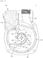
- FIG. 1 is a cut diagram of a principal part of a boiler pump in accordance with an embodiment of the present disclosure
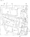
- FIG. 2 is a cross-sectional diagram of the principal part of the boiler pump in accordance with the embodiment of the present disclosure
- FIG. 3 is a perspective diagram illustrating a guide of the boiler pump in accordance with the embodiment of the present disclosure
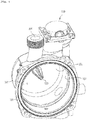
- FIG. 4 is a perspective diagram illustrating a pump housing of the boiler in accordance with the embodiment of the present disclosure.
- a boiler pump 1 in accordance with the embodiment of the present disclosure includes a pump housing 100, a guide 200, and a rib.
- the pump housing 100 can constitute the body of the boiler pump 1 together with a motor housing 400 formed at one side of the pump housing 100.
- the motor housing 400 can include a shaft 410, although not illustrated, a rotor with which the shaft 410 is axially coupled, and a motor portion including a stator rotating the rotor.
- an impeller 300 to which the shaft 410 is fixed can be provided in the pump housing 100 or in the motor housing 400.
- the heating water flowing into the impeller 300 receives the centrifugal force by rotating the impeller 300 as the shaft 410 rotates, and discharged through a heating water outlet 106.
- the pump housing 100 has a space in which one side is opened formed therein.
- the inner side surface of the pump housing 100 includes an end portion surface 101 facing the opened side and a side surface 102 extended from the end portion surface 101.
- a space 103 formed inside the pump housing 100 is determined by the inner side surface thereof.
- the pump housing 100 is formed with a heating water inlet 104 through which the heating water flows into the space 103. And, the pump housing 100 can be also formed with the heating water outlet 106 described above.
- the pump housing 100 is formed with an air outlet 105 through which the air can be discharged from the space 103.
- One side of the pump housing 100, as illustrated, can be provided with an air vent 110.
- the air separated from the heating water in the space 103 can be discharged into the air vent 110 through the air outlet 105.
- the guide 200 includes a base portion 210 and a guiding portion 220.
- the base portion 210 can be a disc shape as an example.
- the base portion 210 is located in the pump housing 100 in order to face the end portion surface 101 of the pump housing 100 in one side direction.
- FIGS. 1 and 2 discloses the structure coupled to the pump housing 100 so that the base portion 210 covers the opened side of the space 103 in the pump housing 100.
- the heating water inlet 104 can be formed at the location of the pump housing 100 so that the heating water flows into the space 103 between the base portion 210 and the end portion surface 101.
- the impeller 300 can be located at the other side direction thereof.
- the base portion 210 is formed with a through-hole 211 through which the heating water passes for the heating water to flow toward the impeller 300.
- the example illustrated discloses the example that the through-hole 211 is formed at the center of the base portion 210.
- the guiding portion 220 is formed to be protruded toward the end portion surface 101 from the base portion 210.
- the longitudinal direction, as illustrated in FIG. 1 is formed to be curved along the periphery of the through-hole 211.
- a door 223 separated from each other and into which the heating water flows is interposed between the one end portion of the guiding portion 220 and the portion just before the guiding portion 220 is curved so that one side directional space of the through-hole 211 is not blocked by the guiding portion 220 with respect to the direction of the side surface 102 of the pump housing 100.
- the other portion of the guiding portion 220 can be extended to the heating water inlet 104 formed on the pump housing 100.
- the heating water flowing into the space 103 between the base portion 210 and the end portion surface 101 through the heating water inlet 104 is guided to flow along the longitudinal direction of the guiding portion 220 while passing through the space between the outside surface 221 of the guiding portion 220 and the side surface 102 of the pump housing 100.
- the centrifugal force acts on the heating water and thereby part of the air in the heating water can be separated.
- the heating water reaches an inlet door 223 described above while continuously flowing along the longitudinal direction of the guiding portion 220 and flows into the impeller 300 through the through-hole 211 of the base portion 210 after entering into the space surrounded by an inner surface 222 of the guiding portion 220.
- the boiler pump 1 in accordance with the present disclosure includes a rib.
- the rib is formed to be protruded at the outside surface 221 of the guiding portion 220. And, at least one rib can be formed at the guiding portion 220.
- the rib can be composed of three ribs 231, 232, 233 spaced along the longitudinal direction of the guiding portion 220. And, it can be extended from the base portion 210 to the end of the guiding portion 220 along the width direction of the guiding portion 220.
- the first and second ribs 231, 232 adjacent to the heating water inlet 104 among the three ribs 231, 232, 233 can face the side surface 102 of the pump housing 100 from the outside surface 221 of the guiding portion 220 and have one surfaces 231a, 232a inclined toward the flowing direction of the heating water.
- the first and second ribs 231, 232 are formed as the structure, such that the cross-sectional area of the flow path of the heating water is reduced, and the pressure on the heating water reduces while the flow rate of the heating water increases. Accordingly, the pressure condition that small bubbles in the heating water can be collected as large bubbles is secured.
- the heating water flows while moving toward the side surface 102 of the pump housing 100 by the first and second ribs 231, 232. That is, the flowing trajectory of the heating water becomes longer. Accordingly, the time condition that small bubbles in the heating water can be collected as large bubbles is secured.
- part of the heating water flowing along the guiding portion 220 can flow along the waveform trajectory, and the air can be effectively separated from the heating water in the process of oscillating with waveform.
- the boiler pump 1 in accordance with the present embodiment can satisfactorily achieve the gas-water separation performance.
- the third rib 233 lastly located among the three ribs 231, 232, 233 is protruded from the outside surface 221 of the guiding portion 220 like the first and second ribs 231, 232 described above.
- the third rib 233 can be formed at the location adjacent to the air outlet 105, and can include one surface 233a facing the air outlet 105 from the outside surface 221 of the guiding portion 220.
- the illustrated example shows that the one surface 233a included in the third rib 233 can be formed as the surface having a lager angle with respect to the outside surface 221 of the guiding portion 220 by comparing with the first and second ribs 231, 232 described above.
- the third rib 233 performs the same function as the first and second ribs 231, 232 and particularly, includes the one surface 233a facing the air outlet 105, thus guiding the direction so that the air separated from the heating water flows toward the air outlet 105.
- the air separated from the heating water can be easily discharged into the air vent 110 through the air outlet 105 by the third rib 233.
- the heating water reaching the end portion of the guiding portion 220 via the third rib 233 flows through the inlet door 223 of the heating water described above, and then passes through the through-hole 211, and in this time, cavitation is caused due to the pressure reduction while the bubbles in the heating water are formed. Due to the phenomenon, there are the problems that noise and vibration are caused, pump parts such as the impeller 300 are damaged by vibration, or performance of the boiler pump 1 is deteriorated.
- the boiler pump 1 in accordance with the present embodiment can further include a boss 120 in order to suppress the cavitation.
- the boss 120 which is protruded at the end portion surface 101 of the pump housing 100 in the direction facing the through-hole 211 and extended to the space surrounded by the inner surface 222 of the guiding portion 220.
- the boss 120 of the example illustrated in FIGS. 2 to 4 has the cross-section of the ⁇ + ⁇ shape, and thereby includes the uneven surface on the outside surface thereof. And, the boss 120, as illustrated, can have the structure that the cross-sectional area reduces toward the end.
- the heating water flowing through the inlet door 223 forms vortex by the boss 120.
- the flow rate of the heating water is reduced due to the friction with the boss 120.
- the pressure on the heating water is increased. Accordingly, the bubble formation in the heating water is suppressed.
- the boiler pump 1 in accordance with the present embodiment provides the advantages that enhance the gas-water separation performance by the rib structure described above, and of course, by forming the boss 120 in the pump housing 100, suppress the cavitation.
- the shaft 410 is rotated by the operation of the motor portion and the impeller 300 is integrally rotated depending upon the rotation of the shaft 410.
- FIG. 1 illustrates the flowing direction of the heating water as the arrow direction of the solid line. In the flowing procedure, the air in the heating water is easily separated by the ribs 231, 232, 233.
- the separated air can be collected from small bubbles to large bubbles.
- the collected bubbles are discharged through the air outlet 105 while moving together with the flow of the heating water, particularly, moving so that its direction is converted together with the heating water when passing through the third rib 233 to be close to the air outlet 105.
- FIG. 1 illustrates the moving path of the air as the arrow direction of the broken line.
- the heating water flows into the space surrounded by the inner surface 222 of the guiding portion 220 through the heating water inlet door 223 at which the end portion of the guiding portion 220 is formed. After inflow, vortex is formed while rubbing against the boss 120 (referring to the solid arrow direction in FIG. 2 ), and in this procedure, the pressure increases to suppress the bubble formation in the heating water.
- the heating water flows toward the impeller 300 through the through-hole 211 of the base portion 210 in the state that the bubble formation is suppressed.
- the heating water flowing toward the impeller 300 is discharged through the heating water outlet 106 while receiving the centrifugal force by the rotation of the impeller 300.
- pump 100 pump housing 101: end portion surface 102: side surface 103: space 104: heating water inlet 105: air outlet 106: heating water outlet 110: air vent 120: boss 200: guide 210: base portion 211: through-hole 220: guiding portion 231: first rib 232: second rib 233: third rib 300: impeller 400: motor housing 410: shaft
Landscapes
- Engineering & Computer Science (AREA)
- Mechanical Engineering (AREA)
- General Engineering & Computer Science (AREA)
- Physics & Mathematics (AREA)
- Thermal Sciences (AREA)
- Chemical & Material Sciences (AREA)
- Combustion & Propulsion (AREA)
- Structures Of Non-Positive Displacement Pumps (AREA)
Abstract
Description
- The present disclosure relates to a boiler pump, and more particularly, to a boiler pump that enhances the gas-water separation performance and the reduction effect of cavitation.
- Various types of pumps are used as a transport means for fluid, and an example of using the pump, for example, can be the pump provided in a heating pipe in order to circulate heating water in a boiler.
- Herein, the boiler is composed of the structure that performs the heating by heating the heating water in a heat exchanger using the heat generated by burning fuel, for example, gas in a combustion chamber and then circulating the heating water through the heating pipe.
- The boiler includes a pump for circulating the heating water to constitute a heating circuit that supplies and returns the heating water, and the heating water is circulated in the state that the air mixed in the heating water is removed using the gas-water separation device.
- A detailed example of the boiler pump to which the gas-water separation device is applied can be the boiler pump disclosed in Korean Registered Utility Model No.
20-0104180 - The Registered Utility Model discloses the boiler pump installed with the body of the gas-water separation device, which separates the gas-water by a gas-water separation plate upon circulation of the heating water and removes air bubbles in the heating water through a cock by operation of a floating body, in the pump housing inducing the heating water; and particularly, a flow-path guide wing of the gas-water separation plate is inclined with respect to the tangential direction of the flow path, the cross-sectional area of the flow path is formed by a flow path B, a flow path A, and a flow path C, and a bubble collection chamber is formed on the upper portion of the flow path B.
- However, the boiler pump having the conventional gas-water separation device including the Registered Utility Model has the problem that the gas-water separation performance cannot be satisfactorily attained despite the gas-water separation device not to perform the circulation of the heating water, and thereby the heating efficiency is deteriorated.
- In addition, in the structure of the conventional boiler pump, cavitation at the front end of a pump impeller when increasing a flow rate of the heating water in the pump housing for only the gas-water separation is caused. Thus, there are the problems that impact is applied to the impeller, thus causing pump noise and deteriorating the durability of the pump.
- The present disclosure is proposed to solve the above problems of the related art, and an object of the present disclosure is to provide a boiler pump enhancing the gas-water separation performance by applying the structure changing the flowing direction while reducing the cross-sectional area of the flow path of the heating water in the pump housing.
- In addition, another object of the present disclosure is to provide the boiler pump reducing the cavitation by forming the boss at the front end of the pump impeller.
- A boiler pump in accordance with an embodiment of the present disclosure a pump housing having a space formed therein which is determined by an end portion surface and a side surface extending from the end portion surface, and provided with a heating water inlet through which heating water can flow into the space and an air outlet through which air can be discharged from the space; a guide comprising a base portion located to face the end portion surface in the pump housing and formed with a through-hole through which the heating water passes in order to flow toward an impeller side, and a guiding portion protruded toward the end portion surface at the base portion and formed so that the longitudinal direction thereof is bent along the periphery of the through-hole to guide so that the heating water flowing through the heating water inlet flows along the longitudinal direction while passing through the space between an outside surface of the guiding portion and the side surface and then is directed to the through-hole; and at least one rib protruded from the outside surface of the guiding portion.
- According to the boiler pump in accordance with the embodiment of the present disclosure, the rib can be formed to extend from the base portion to the end of the guiding portion along the width direction of the guiding portion.
- According to the boiler pump in accordance with the embodiment of the present disclosure, the rib can include one surface facing the side surface from the outside surface and inclined toward a flowing direction of the heating water.
- According to the boiler pump in accordance with the embodiment of the present disclosure, the rib can include one surface facing the air outlet from the outside surface.
- According to the boiler pump in accordance with the embodiment of the present disclosure, the rib can be formed to extend from the base portion to the end of the guiding portion along the width direction of the guiding portion and formed in plural to be spaced along the longitudinal direction of the guiding portion, and one of the plurality of ribs located closest to the air outlet can include one surface facing the air outlet from the outside surface and the remaining plurality of ribs can include one surface facing the side surface from the outside surface and inclined toward the flowing direction of the heating water.
- According to the boiler pump in accordance with the embodiment of the present disclosure, a boss protruding in the direction facing the through-hole and extending to the space surrounded by the inner surface of the guiding portion can be formed on the end portion surface of the pump housing.
- According to the boiler pump in accordance with the embodiment of the present disclosure, the boss can include an uneven surface on the outside surface thereof.
- According to the boiler pump in accordance with the embodiment of the present disclosure, the boss has decreasing cross-sectional area toward the end thereof.
- In accordance with the present disclosure, by forming at least one rib in the guiding portion of the guide, the pressure on the heating water is reduced by the rib as the flow rate of the heating water increase. And, as the heating water flows toward the side surface of the pump housing, the flowing trajectory becomes longer. Accordingly, the pressure and the time conditions in which small bubbles in the heating water can be collected as large bubbles are secured, thus greatly enhancing the gas-water separation performance.
- In addition, by including one surface of the rib facing the air outlet, the bubbles collected by separating from the heating water can be easily discharged through the air outlet.
- In addition, there is the effect in that by increasing the pressure on the heating water before flowing into the impeller, the bubble formation in the heating water is suppressed by the boss formed on the pump housing and thereby cavitation is suppressed.
-
-
FIG. 1 is a cut diagram of a principal part of a boiler pump in accordance with an embodiment of the present disclosure. -
FIG. 2 is a cross-sectional diagram of the principal part of the boiler pump in accordance with the embodiment of the present disclosure. -
FIG. 3 is a perspective diagram illustrating a guide of the boiler pump in accordance with the embodiment of the present disclosure. -
FIG. 4 is a perspective diagram illustrating a pump housing of the boiler pump in accordance with the embodiment of the present disclosure. - Hereinafter, the boiler pump in accordance with the embodiment of the present disclosure will be described in detail with reference to the accompanying drawings.
-
FIG. 1 is a cut diagram of a principal part of a boiler pump in accordance with an embodiment of the present disclosure,FIG. 2 is a cross-sectional diagram of the principal part of the boiler pump in accordance with the embodiment of the present disclosure,FIG. 3 is a perspective diagram illustrating a guide of the boiler pump in accordance with the embodiment of the present disclosure, andFIG. 4 is a perspective diagram illustrating a pump housing of the boiler in accordance with the embodiment of the present disclosure. - A boiler pump 1 in accordance with the embodiment of the present disclosure includes a
pump housing 100, aguide 200, and a rib. - The
pump housing 100 can constitute the body of the boiler pump 1 together with amotor housing 400 formed at one side of thepump housing 100. - The
motor housing 400 can include ashaft 410, although not illustrated, a rotor with which theshaft 410 is axially coupled, and a motor portion including a stator rotating the rotor. - And, an
impeller 300 to which theshaft 410 is fixed can be provided in thepump housing 100 or in themotor housing 400. The heating water flowing into theimpeller 300 receives the centrifugal force by rotating theimpeller 300 as theshaft 410 rotates, and discharged through aheating water outlet 106. - The pump housing 100, as illustrated in
FIG. 4 , has a space in which one side is opened formed therein. The inner side surface of thepump housing 100 includes anend portion surface 101 facing the opened side and aside surface 102 extended from theend portion surface 101. Aspace 103 formed inside thepump housing 100 is determined by the inner side surface thereof. - The
pump housing 100 is formed with aheating water inlet 104 through which the heating water flows into thespace 103. And, thepump housing 100 can be also formed with theheating water outlet 106 described above. - The
pump housing 100 is formed with anair outlet 105 through which the air can be discharged from thespace 103. One side of thepump housing 100, as illustrated, can be provided with anair vent 110. The air separated from the heating water in thespace 103 can be discharged into theair vent 110 through theair outlet 105. - The
guide 200 includes abase portion 210 and a guidingportion 220. Thebase portion 210 can be a disc shape as an example. Thebase portion 210 is located in thepump housing 100 in order to face theend portion surface 101 of thepump housing 100 in one side direction. - The embodiment illustrated in
FIGS. 1 and2 discloses the structure coupled to thepump housing 100 so that thebase portion 210 covers the opened side of thespace 103 in thepump housing 100. In the structure, theheating water inlet 104 can be formed at the location of thepump housing 100 so that the heating water flows into thespace 103 between thebase portion 210 and theend portion surface 101. - As illustrated in
FIG. 2 , theimpeller 300 can be located at the other side direction thereof. Thebase portion 210 is formed with a through-hole 211 through which the heating water passes for the heating water to flow toward theimpeller 300. The example illustrated discloses the example that the through-hole 211 is formed at the center of thebase portion 210. - As illustrated in
FIG. 3 , the guidingportion 220 is formed to be protruded toward theend portion surface 101 from thebase portion 210. And, the longitudinal direction, as illustrated inFIG. 1 , is formed to be curved along the periphery of the through-hole 211. - In this time, a
door 223 separated from each other and into which the heating water flows is interposed between the one end portion of the guidingportion 220 and the portion just before the guidingportion 220 is curved so that one side directional space of the through-hole 211 is not blocked by the guidingportion 220 with respect to the direction of theside surface 102 of thepump housing 100. - Meanwhile, the other portion of the guiding
portion 220 can be extended to theheating water inlet 104 formed on thepump housing 100. - The heating water flowing into the
space 103 between thebase portion 210 and theend portion surface 101 through theheating water inlet 104 is guided to flow along the longitudinal direction of the guidingportion 220 while passing through the space between theoutside surface 221 of the guidingportion 220 and theside surface 102 of thepump housing 100. In this procedure, the centrifugal force acts on the heating water and thereby part of the air in the heating water can be separated. - The heating water reaches an
inlet door 223 described above while continuously flowing along the longitudinal direction of the guidingportion 220 and flows into theimpeller 300 through the through-hole 211 of thebase portion 210 after entering into the space surrounded by aninner surface 222 of the guidingportion 220. - Meanwhile, in the structure of the above-described pump 1, when the flow rate of the heating water is fast, the time when small bubbles in the heating water are collected is not secured, and thereby the heating water can flow into the
impeller 300 without proper separation of the air in the heating water. - In order to solve the problem, the boiler pump 1 in accordance with the present disclosure includes a rib. The rib is formed to be protruded at the
outside surface 221 of the guidingportion 220. And, at least one rib can be formed at the guidingportion 220. - A detailed example of the rib structure is illustrated in
FIGS. 1 to 3 . Like the example illustrated, the rib can be composed of threeribs portion 220. And, it can be extended from thebase portion 210 to the end of the guidingportion 220 along the width direction of the guidingportion 220. - In this time, the first and
second ribs heating water inlet 104 among the threeribs side surface 102 of thepump housing 100 from theoutside surface 221 of the guidingportion 220 and have onesurfaces - The first and
second ribs - In addition, the heating water flows while moving toward the
side surface 102 of thepump housing 100 by the first andsecond ribs - And, by forming the unevenness on the
outside surface 221 of the guidingportion 220 by the first andsecond ribs portion 220 can flow along the waveform trajectory, and the air can be effectively separated from the heating water in the process of oscillating with waveform. - Thus, by securing the pressure and the time conditions that small bubbles in the heating water can be collected as large bubbles, the boiler pump 1 in accordance with the present embodiment can satisfactorily achieve the gas-water separation performance.
- Meanwhile, the
third rib 233 lastly located among the threeribs outside surface 221 of the guidingportion 220 like the first andsecond ribs - The
third rib 233 can be formed at the location adjacent to theair outlet 105, and can include onesurface 233a facing theair outlet 105 from theoutside surface 221 of the guidingportion 220. - The illustrated example shows that the one
surface 233a included in thethird rib 233 can be formed as the surface having a lager angle with respect to theoutside surface 221 of the guidingportion 220 by comparing with the first andsecond ribs - The
third rib 233 performs the same function as the first andsecond ribs surface 233a facing theair outlet 105, thus guiding the direction so that the air separated from the heating water flows toward theair outlet 105. - The air separated from the heating water can be easily discharged into the
air vent 110 through theair outlet 105 by thethird rib 233. - The heating water reaching the end portion of the guiding
portion 220 via thethird rib 233 flows through theinlet door 223 of the heating water described above, and then passes through the through-hole 211, and in this time, cavitation is caused due to the pressure reduction while the bubbles in the heating water are formed. Due to the phenomenon, there are the problems that noise and vibration are caused, pump parts such as theimpeller 300 are damaged by vibration, or performance of the boiler pump 1 is deteriorated. - The boiler pump 1 in accordance with the present embodiment can further include a
boss 120 in order to suppress the cavitation. - Specifically, the
boss 120, which is protruded at theend portion surface 101 of thepump housing 100 in the direction facing the through-hole 211 and extended to the space surrounded by theinner surface 222 of the guidingportion 220. - The
boss 120 of the example illustrated inFIGS. 2 to 4 has the cross-section of the ┌+┘ shape, and thereby includes the uneven surface on the outside surface thereof. And, theboss 120, as illustrated, can have the structure that the cross-sectional area reduces toward the end. - The heating water flowing through the
inlet door 223 forms vortex by theboss 120. In this procedure, the flow rate of the heating water is reduced due to the friction with theboss 120. And, the pressure on the heating water is increased. Accordingly, the bubble formation in the heating water is suppressed. - The boiler pump 1 in accordance with the present embodiment provides the advantages that enhance the gas-water separation performance by the rib structure described above, and of course, by forming the
boss 120 in thepump housing 100, suppress the cavitation. - The operation procedure of the boiler pump 1 in accordance with the present embodiment will be described as follows.
- If the boiler pump 1 operates, the
shaft 410 is rotated by the operation of the motor portion and theimpeller 300 is integrally rotated depending upon the rotation of theshaft 410. - The heating water, which flows into the
space 103 in thepump housing 100 through theheating water inlet 104, specifically, thespace 103 between theend portion surface 101 and thebase portion 210, flows by being guided by the guidingportion 220.FIG. 1 illustrates the flowing direction of the heating water as the arrow direction of the solid line. In the flowing procedure, the air in the heating water is easily separated by theribs - The separated air can be collected from small bubbles to large bubbles. The collected bubbles are discharged through the
air outlet 105 while moving together with the flow of the heating water, particularly, moving so that its direction is converted together with the heating water when passing through thethird rib 233 to be close to theair outlet 105.FIG. 1 illustrates the moving path of the air as the arrow direction of the broken line. - The heating water flows into the space surrounded by the
inner surface 222 of the guidingportion 220 through the heatingwater inlet door 223 at which the end portion of the guidingportion 220 is formed. After inflow, vortex is formed while rubbing against the boss 120 (referring to the solid arrow direction inFIG. 2 ), and in this procedure, the pressure increases to suppress the bubble formation in the heating water. - The heating water flows toward the
impeller 300 through the through-hole 211 of thebase portion 210 in the state that the bubble formation is suppressed. The heating water flowing toward theimpeller 300 is discharged through theheating water outlet 106 while receiving the centrifugal force by the rotation of theimpeller 300. - While the present disclosure has been described with respect to the detailed embodiments, it will be apparent to those skilled in the art that the present disclosure is an example for explaining the preset disclosure in detail and is not limited thereto, and various changes or improvements may be made without departing from the spirit the present disclosure.
-
1: pump 100: pump housing 101: end portion surface 102: side surface 103: space 104: heating water inlet 105: air outlet 106: heating water outlet 110: air vent 120: boss 200: guide 210: base portion 211: through-hole 220: guiding portion 231: first rib 232: second rib 233: third rib 300: impeller 400: motor housing 410: shaft
Claims (8)
- A boiler pump, comprising:a pump housing having a space formed therein which is determined by an end portion surface and a side surface extending from the end portion surface, and provided with a heating water inlet through which heating water can flow into the space and an air outlet through which air can be discharged from the space;a guide comprising a base portion located to face the end portion surface in the pump housing and formed with a through-hole through which the heating water passes in order to flow toward an impeller side, and a guiding portion protruded toward the end portion surface from the base portion and formed so that the longitudinal direction thereof is curved along the periphery of the through-hole, and guiding so that the heating water flowing through the heating water inlet flows along the longitudinal direction and then flows toward the through-hole while passing through the space between an outside surface of the guiding portion and the side surface; andat least one rib protruded from the outside surface of the guiding portion.
- The boiler pump according to claim 1, wherein the rib is formed to extend from the base portion to the end of the guiding portion along the width direction of the guiding portion.
- The boiler pump according to claim 1, wherein the rib comprises one surface facing the side surface from the outside surface and inclined toward a flowing direction of the heating water.
- The boiler pump according to claim 1, wherein the rib comprises one surface facing the air outlet from the outside surface.
- The boiler pump according to claim 1, wherein the rib is formed to extend from the base portion to the end of the guiding portion along the width direction of the guiding portion and formed in plural to be spaced along the longitudinal direction of the guiding portion; and one of the plurality of ribs located closest to the air outlet comprises one surface facing the air outlet from the outside surface, and the remaining plurality of ribs comprise one surface facing the side surface from the outside surface and inclined toward the flowing direction of the heating water.
- The boiler pump according to any one of claims 1 to 5, wherein a boss protruding in the direction facing the through-hole and extending to the space surrounded by the inner surface of the guiding portion is formed on the end portion surface of the pump housing.
- The boiler pump according to claim 6, wherein the boss comprises an uneven surface on the outside surface thereof.
- The boiler pump according to claim 6, wherein the boss has decreasing cross-sectional area toward the end thereof.
Applications Claiming Priority (2)
| Application Number | Priority Date | Filing Date | Title |
|---|---|---|---|
| KR1020150148914A KR101832131B1 (en) | 2015-10-26 | 2015-10-26 | A pump for boiler |
| PCT/KR2016/011993 WO2017073975A1 (en) | 2015-10-26 | 2016-10-25 | Boiler pump |
Publications (2)
| Publication Number | Publication Date |
|---|---|
| EP3369940A1 true EP3369940A1 (en) | 2018-09-05 |
| EP3369940A4 EP3369940A4 (en) | 2019-06-12 |
Family
ID=58631780
Family Applications (1)
| Application Number | Title | Priority Date | Filing Date |
|---|---|---|---|
| EP16860158.1A Withdrawn EP3369940A4 (en) | 2015-10-26 | 2016-10-25 | BOILER PUMP |
Country Status (5)
| Country | Link |
|---|---|
| EP (1) | EP3369940A4 (en) |
| KR (1) | KR101832131B1 (en) |
| CN (1) | CN108138801B (en) |
| RU (1) | RU2688076C1 (en) |
| WO (1) | WO2017073975A1 (en) |
Families Citing this family (8)
| Publication number | Priority date | Publication date | Assignee | Title |
|---|---|---|---|---|
| FR3078116B1 (en) * | 2018-02-22 | 2021-09-10 | Ksb Sas | FINGER PUMP |
| JP2020180579A (en) * | 2019-04-25 | 2020-11-05 | 株式会社鷺宮製作所 | Centrifugal pump and cooling system using the same |
| KR102819870B1 (en) * | 2020-02-17 | 2025-06-11 | 엘지전자 주식회사 | Pump |
| KR102798841B1 (en) * | 2020-02-28 | 2025-04-22 | 엘지전자 주식회사 | Gas separation device for the fluid circulation pump |
| KR102828707B1 (en) * | 2020-02-28 | 2025-07-03 | 엘지전자 주식회사 | Pump |
| KR102909689B1 (en) | 2020-12-31 | 2026-01-09 | 주식회사 경동나비엔 | Circulation pump |
| KR102909688B1 (en) | 2020-12-31 | 2026-01-09 | 주식회사 경동나비엔 | Circulation pump |
| CN118959351B (en) * | 2024-08-13 | 2025-12-09 | 安徽新沪屏蔽泵有限责任公司 | Centrifugal pump device |
Family Cites Families (10)
| Publication number | Priority date | Publication date | Assignee | Title |
|---|---|---|---|---|
| BE794198A (en) * | 1972-03-09 | 1973-05-16 | Saunier Duval | DEGAZER PUMP-TRAP ASSEMBLY FOR CENTRAL HEATING SYSTEMS |
| SU1267053A1 (en) * | 1984-04-04 | 1986-10-30 | Предприятие П/Я А-7116 | Centrifugal self-priming pump of recirculation type |
| KR960009753Y1 (en) * | 1993-12-16 | 1996-11-06 | 주식회사 경동보일러 | Separation device attached to the circulation pump of the boiler |
| KR200189324Y1 (en) * | 1999-12-28 | 2000-07-15 | 최진민 | An air exhaust structure of hot water circulation pump |
| US6471476B1 (en) * | 2000-11-13 | 2002-10-29 | Wacker Corporation | Centrifugal trash pump |
| JP4872456B2 (en) * | 2006-05-24 | 2012-02-08 | パナソニック電工株式会社 | Pump and liquid supply device |
| DE102008052884A1 (en) * | 2008-10-23 | 2010-05-06 | Wilo Se | pump housing |
| ATE507393T1 (en) * | 2009-05-18 | 2011-05-15 | Wilo Se | CENTRIFUGAL PUMP WITH VENTILATION SPACE |
| JP6022779B2 (en) * | 2012-03-01 | 2016-11-09 | 株式会社横田製作所 | Self-priming centrifugal pump device |
| KR101447440B1 (en) * | 2013-05-15 | 2014-10-06 | 이남 | double volute pump |
-
2015
- 2015-10-26 KR KR1020150148914A patent/KR101832131B1/en active Active
-
2016
- 2016-10-25 EP EP16860158.1A patent/EP3369940A4/en not_active Withdrawn
- 2016-10-25 CN CN201680062891.0A patent/CN108138801B/en active Active
- 2016-10-25 WO PCT/KR2016/011993 patent/WO2017073975A1/en not_active Ceased
- 2016-10-25 RU RU2018118609A patent/RU2688076C1/en active
Also Published As
| Publication number | Publication date |
|---|---|
| EP3369940A4 (en) | 2019-06-12 |
| CN108138801A (en) | 2018-06-08 |
| RU2688076C1 (en) | 2019-05-17 |
| KR101832131B1 (en) | 2018-02-26 |
| KR20170048044A (en) | 2017-05-08 |
| CN108138801B (en) | 2020-05-05 |
| WO2017073975A1 (en) | 2017-05-04 |
Similar Documents
| Publication | Publication Date | Title |
|---|---|---|
| CN108138801B (en) | boiler pump | |
| EP2813711B1 (en) | Circulation pump | |
| KR200477242Y1 (en) | a underwater pump | |
| KR101393054B1 (en) | Adapter for preventing cavitaion and centrifugal pump having adapter | |
| KR101540403B1 (en) | Centrifugal Impeller Having External Blade and Pump thereof | |
| US8283823B2 (en) | Motor shield for the drainage device of a cooling or air-conditioning system | |
| KR101826600B1 (en) | Pump for Circulating Water | |
| KR102195428B1 (en) | Drain pump | |
| KR102402559B1 (en) | Electric water pump | |
| KR101933342B1 (en) | Impeller for water pump with curved wing structure and water pump applied with the same | |
| US6481958B1 (en) | Side channel pump | |
| KR101827295B1 (en) | Pump for Circulating Hot Water | |
| KR101869827B1 (en) | Pump for Circulating Water | |
| KR20200042148A (en) | Impeller for electric water pump | |
| JP7357356B2 (en) | drain pump | |
| JP6014522B2 (en) | Self-priming pump | |
| KR200440266Y1 (en) | Casing for the pump | |
| JP2013057275A (en) | Centrifugal pump | |
| US20040136823A1 (en) | Impeller for automotive fuel pump | |
| KR101567534B1 (en) | Pump Having Suction Casing with Flow Guides | |
| JP2006144735A (en) | Water pump | |
| KR20160106409A (en) | Impeller and water pump with the same | |
| JP2012067617A (en) | Water pump | |
| KR102311191B1 (en) | Drain pump | |
| KR20210109796A (en) | Gas separation device for the fluid circulation pump |
Legal Events
| Date | Code | Title | Description |
|---|---|---|---|
| STAA | Information on the status of an ep patent application or granted ep patent |
Free format text: STATUS: THE INTERNATIONAL PUBLICATION HAS BEEN MADE |
|
| PUAI | Public reference made under article 153(3) epc to a published international application that has entered the european phase |
Free format text: ORIGINAL CODE: 0009012 |
|
| STAA | Information on the status of an ep patent application or granted ep patent |
Free format text: STATUS: REQUEST FOR EXAMINATION WAS MADE |
|
| 17P | Request for examination filed |
Effective date: 20180426 |
|
| AK | Designated contracting states |
Kind code of ref document: A1 Designated state(s): AL AT BE BG CH CY CZ DE DK EE ES FI FR GB GR HR HU IE IS IT LI LT LU LV MC MK MT NL NO PL PT RO RS SE SI SK SM TR |
|
| AX | Request for extension of the european patent |
Extension state: BA ME |
|
| DAV | Request for validation of the european patent (deleted) | ||
| DAX | Request for extension of the european patent (deleted) | ||
| A4 | Supplementary search report drawn up and despatched |
Effective date: 20190515 |
|
| RIC1 | Information provided on ipc code assigned before grant |
Ipc: F04D 29/44 20060101AFI20190509BHEP Ipc: F24H 9/00 20060101ALI20190509BHEP Ipc: F04D 9/00 20060101ALI20190509BHEP Ipc: F04D 29/66 20060101ALI20190509BHEP |
|
| GRAP | Despatch of communication of intention to grant a patent |
Free format text: ORIGINAL CODE: EPIDOSNIGR1 |
|
| STAA | Information on the status of an ep patent application or granted ep patent |
Free format text: STATUS: GRANT OF PATENT IS INTENDED |
|
| INTG | Intention to grant announced |
Effective date: 20210212 |
|
| STAA | Information on the status of an ep patent application or granted ep patent |
Free format text: STATUS: THE APPLICATION IS DEEMED TO BE WITHDRAWN |
|
| 18D | Application deemed to be withdrawn |
Effective date: 20210623 |