EP3369900A1 - Cooling device for reductant spray module, and selective engine cooling sytem having same - Google Patents
Cooling device for reductant spray module, and selective engine cooling sytem having same Download PDFInfo
- Publication number
- EP3369900A1 EP3369900A1 EP16862520.0A EP16862520A EP3369900A1 EP 3369900 A1 EP3369900 A1 EP 3369900A1 EP 16862520 A EP16862520 A EP 16862520A EP 3369900 A1 EP3369900 A1 EP 3369900A1
- Authority
- EP
- European Patent Office
- Prior art keywords
- coolant
- vapor
- engine
- line
- reducing agent
- Prior art date
- Legal status (The legal status is an assumption and is not a legal conclusion. Google has not performed a legal analysis and makes no representation as to the accuracy of the status listed.)
- Granted
Links
Images



Classifications
-
- F—MECHANICAL ENGINEERING; LIGHTING; HEATING; WEAPONS; BLASTING
- F01—MACHINES OR ENGINES IN GENERAL; ENGINE PLANTS IN GENERAL; STEAM ENGINES
- F01N—GAS-FLOW SILENCERS OR EXHAUST APPARATUS FOR MACHINES OR ENGINES IN GENERAL; GAS-FLOW SILENCERS OR EXHAUST APPARATUS FOR INTERNAL-COMBUSTION ENGINES
- F01N3/00—Exhaust or silencing apparatus having means for purifying, rendering innocuous, or otherwise treating exhaust
- F01N3/08—Exhaust or silencing apparatus having means for purifying, rendering innocuous, or otherwise treating exhaust for rendering innocuous
- F01N3/10—Exhaust or silencing apparatus having means for purifying, rendering innocuous, or otherwise treating exhaust for rendering innocuous by thermal or catalytic conversion of noxious components of exhaust
- F01N3/18—Exhaust or silencing apparatus having means for purifying, rendering innocuous, or otherwise treating exhaust for rendering innocuous by thermal or catalytic conversion of noxious components of exhaust characterised by methods of operation; Control
- F01N3/20—Exhaust or silencing apparatus having means for purifying, rendering innocuous, or otherwise treating exhaust for rendering innocuous by thermal or catalytic conversion of noxious components of exhaust characterised by methods of operation; Control specially adapted for catalytic conversion
- F01N3/206—Adding periodically or continuously substances to exhaust gases for promoting purification, e.g. catalytic material in liquid form, NOx reducing agents
- F01N3/208—Control of selective catalytic reduction [SCR], e.g. by adjusting the dosing of reducing agent
-
- F—MECHANICAL ENGINEERING; LIGHTING; HEATING; WEAPONS; BLASTING
- F01—MACHINES OR ENGINES IN GENERAL; ENGINE PLANTS IN GENERAL; STEAM ENGINES
- F01N—GAS-FLOW SILENCERS OR EXHAUST APPARATUS FOR MACHINES OR ENGINES IN GENERAL; GAS-FLOW SILENCERS OR EXHAUST APPARATUS FOR INTERNAL-COMBUSTION ENGINES
- F01N13/00—Exhaust or silencing apparatus characterised by constructional features
- F01N13/08—Other arrangements or adaptations of exhaust conduits
- F01N13/10—Other arrangements or adaptations of exhaust conduits of exhaust manifolds
-
- F—MECHANICAL ENGINEERING; LIGHTING; HEATING; WEAPONS; BLASTING
- F01—MACHINES OR ENGINES IN GENERAL; ENGINE PLANTS IN GENERAL; STEAM ENGINES
- F01N—GAS-FLOW SILENCERS OR EXHAUST APPARATUS FOR MACHINES OR ENGINES IN GENERAL; GAS-FLOW SILENCERS OR EXHAUST APPARATUS FOR INTERNAL-COMBUSTION ENGINES
- F01N3/00—Exhaust or silencing apparatus having means for purifying, rendering innocuous, or otherwise treating exhaust
- F01N3/08—Exhaust or silencing apparatus having means for purifying, rendering innocuous, or otherwise treating exhaust for rendering innocuous
- F01N3/0807—Exhaust or silencing apparatus having means for purifying, rendering innocuous, or otherwise treating exhaust for rendering innocuous by using absorbents or adsorbents
- F01N3/0828—Exhaust or silencing apparatus having means for purifying, rendering innocuous, or otherwise treating exhaust for rendering innocuous by using absorbents or adsorbents characterised by the absorbed or adsorbed substances
- F01N3/0842—Nitrogen oxides
-
- F—MECHANICAL ENGINEERING; LIGHTING; HEATING; WEAPONS; BLASTING
- F01—MACHINES OR ENGINES IN GENERAL; ENGINE PLANTS IN GENERAL; STEAM ENGINES
- F01N—GAS-FLOW SILENCERS OR EXHAUST APPARATUS FOR MACHINES OR ENGINES IN GENERAL; GAS-FLOW SILENCERS OR EXHAUST APPARATUS FOR INTERNAL-COMBUSTION ENGINES
- F01N3/00—Exhaust or silencing apparatus having means for purifying, rendering innocuous, or otherwise treating exhaust
- F01N3/08—Exhaust or silencing apparatus having means for purifying, rendering innocuous, or otherwise treating exhaust for rendering innocuous
- F01N3/10—Exhaust or silencing apparatus having means for purifying, rendering innocuous, or otherwise treating exhaust for rendering innocuous by thermal or catalytic conversion of noxious components of exhaust
- F01N3/18—Exhaust or silencing apparatus having means for purifying, rendering innocuous, or otherwise treating exhaust for rendering innocuous by thermal or catalytic conversion of noxious components of exhaust characterised by methods of operation; Control
- F01N3/20—Exhaust or silencing apparatus having means for purifying, rendering innocuous, or otherwise treating exhaust for rendering innocuous by thermal or catalytic conversion of noxious components of exhaust characterised by methods of operation; Control specially adapted for catalytic conversion
- F01N3/206—Adding periodically or continuously substances to exhaust gases for promoting purification, e.g. catalytic material in liquid form, NOx reducing agents
- F01N3/2066—Selective catalytic reduction [SCR]
-
- F—MECHANICAL ENGINEERING; LIGHTING; HEATING; WEAPONS; BLASTING
- F01—MACHINES OR ENGINES IN GENERAL; ENGINE PLANTS IN GENERAL; STEAM ENGINES
- F01P—COOLING OF MACHINES OR ENGINES IN GENERAL; COOLING OF INTERNAL-COMBUSTION ENGINES
- F01P11/00—Component parts, details, or accessories not provided for in, or of interest apart from, groups F01P1/00 - F01P9/00
- F01P11/02—Liquid-coolant filling, overflow, venting, or draining devices
- F01P11/029—Expansion reservoirs
-
- F—MECHANICAL ENGINEERING; LIGHTING; HEATING; WEAPONS; BLASTING
- F01—MACHINES OR ENGINES IN GENERAL; ENGINE PLANTS IN GENERAL; STEAM ENGINES
- F01N—GAS-FLOW SILENCERS OR EXHAUST APPARATUS FOR MACHINES OR ENGINES IN GENERAL; GAS-FLOW SILENCERS OR EXHAUST APPARATUS FOR INTERNAL-COMBUSTION ENGINES
- F01N2240/00—Combination or association of two or more different exhaust treating devices, or of at least one such device with an auxiliary device, not covered by indexing codes F01N2230/00 or F01N2250/00, one of the devices being
- F01N2240/02—Combination or association of two or more different exhaust treating devices, or of at least one such device with an auxiliary device, not covered by indexing codes F01N2230/00 or F01N2250/00, one of the devices being a heat exchanger
-
- F—MECHANICAL ENGINEERING; LIGHTING; HEATING; WEAPONS; BLASTING
- F01—MACHINES OR ENGINES IN GENERAL; ENGINE PLANTS IN GENERAL; STEAM ENGINES
- F01N—GAS-FLOW SILENCERS OR EXHAUST APPARATUS FOR MACHINES OR ENGINES IN GENERAL; GAS-FLOW SILENCERS OR EXHAUST APPARATUS FOR INTERNAL-COMBUSTION ENGINES
- F01N2260/00—Exhaust treating devices having provisions not otherwise provided for
- F01N2260/02—Exhaust treating devices having provisions not otherwise provided for for cooling the device
- F01N2260/024—Exhaust treating devices having provisions not otherwise provided for for cooling the device using a liquid
-
- F—MECHANICAL ENGINEERING; LIGHTING; HEATING; WEAPONS; BLASTING
- F01—MACHINES OR ENGINES IN GENERAL; ENGINE PLANTS IN GENERAL; STEAM ENGINES
- F01N—GAS-FLOW SILENCERS OR EXHAUST APPARATUS FOR MACHINES OR ENGINES IN GENERAL; GAS-FLOW SILENCERS OR EXHAUST APPARATUS FOR INTERNAL-COMBUSTION ENGINES
- F01N2610/00—Adding substances to exhaust gases
- F01N2610/02—Adding substances to exhaust gases the substance being ammonia or urea
-
- F—MECHANICAL ENGINEERING; LIGHTING; HEATING; WEAPONS; BLASTING
- F01—MACHINES OR ENGINES IN GENERAL; ENGINE PLANTS IN GENERAL; STEAM ENGINES
- F01N—GAS-FLOW SILENCERS OR EXHAUST APPARATUS FOR MACHINES OR ENGINES IN GENERAL; GAS-FLOW SILENCERS OR EXHAUST APPARATUS FOR INTERNAL-COMBUSTION ENGINES
- F01N2610/00—Adding substances to exhaust gases
- F01N2610/11—Adding substances to exhaust gases the substance or part of the dosing system being cooled
-
- F—MECHANICAL ENGINEERING; LIGHTING; HEATING; WEAPONS; BLASTING
- F01—MACHINES OR ENGINES IN GENERAL; ENGINE PLANTS IN GENERAL; STEAM ENGINES
- F01N—GAS-FLOW SILENCERS OR EXHAUST APPARATUS FOR MACHINES OR ENGINES IN GENERAL; GAS-FLOW SILENCERS OR EXHAUST APPARATUS FOR INTERNAL-COMBUSTION ENGINES
- F01N2610/00—Adding substances to exhaust gases
- F01N2610/14—Arrangements for the supply of substances, e.g. conduits
- F01N2610/1406—Storage means for substances, e.g. tanks or reservoirs
-
- F—MECHANICAL ENGINEERING; LIGHTING; HEATING; WEAPONS; BLASTING
- F01—MACHINES OR ENGINES IN GENERAL; ENGINE PLANTS IN GENERAL; STEAM ENGINES
- F01N—GAS-FLOW SILENCERS OR EXHAUST APPARATUS FOR MACHINES OR ENGINES IN GENERAL; GAS-FLOW SILENCERS OR EXHAUST APPARATUS FOR INTERNAL-COMBUSTION ENGINES
- F01N2610/00—Adding substances to exhaust gases
- F01N2610/14—Arrangements for the supply of substances, e.g. conduits
- F01N2610/1453—Sprayers or atomisers; Arrangement thereof in the exhaust apparatus
-
- F—MECHANICAL ENGINEERING; LIGHTING; HEATING; WEAPONS; BLASTING
- F01—MACHINES OR ENGINES IN GENERAL; ENGINE PLANTS IN GENERAL; STEAM ENGINES
- F01P—COOLING OF MACHINES OR ENGINES IN GENERAL; COOLING OF INTERNAL-COMBUSTION ENGINES
- F01P2060/00—Cooling circuits using auxiliaries
- F01P2060/16—Outlet manifold
-
- F—MECHANICAL ENGINEERING; LIGHTING; HEATING; WEAPONS; BLASTING
- F01—MACHINES OR ENGINES IN GENERAL; ENGINE PLANTS IN GENERAL; STEAM ENGINES
- F01P—COOLING OF MACHINES OR ENGINES IN GENERAL; COOLING OF INTERNAL-COMBUSTION ENGINES
- F01P3/00—Liquid cooling
- F01P3/12—Arrangements for cooling other engine or machine parts
-
- Y—GENERAL TAGGING OF NEW TECHNOLOGICAL DEVELOPMENTS; GENERAL TAGGING OF CROSS-SECTIONAL TECHNOLOGIES SPANNING OVER SEVERAL SECTIONS OF THE IPC; TECHNICAL SUBJECTS COVERED BY FORMER USPC CROSS-REFERENCE ART COLLECTIONS [XRACs] AND DIGESTS
- Y02—TECHNOLOGIES OR APPLICATIONS FOR MITIGATION OR ADAPTATION AGAINST CLIMATE CHANGE
- Y02T—CLIMATE CHANGE MITIGATION TECHNOLOGIES RELATED TO TRANSPORTATION
- Y02T10/00—Road transport of goods or passengers
- Y02T10/10—Internal combustion engine [ICE] based vehicles
- Y02T10/12—Improving ICE efficiencies
Definitions
- the present invention relates to a coolant circulation system for a reducing agent injection module and a selective catalytic reduction system including the same, more particularly, to a cooling device of a reducing agent injection module for an exhaust gas after-treatment and an engine cooling system including the same.
- a diesel engine using compression-ignition combustion has advantages such as a high expansion ratio, but has disadvantages such as vibrations, emissions of pollutants including nitrogen oxide (NOx) and dust or the like.
- an exhaust gas after-treatment device including a selective catalytic reduction (SCR) device may be provided.
- a reducing agent injection module may be installed in front of the selective catalytic reduction device to inject a reducing agent such as urea toward a flow direction of an exhaust gas.
- the selective catalytic reduction device may react catalytically the reducing agent with nitrogen oxide (NOx) of the exhaust gas such that the nitrogen oxide is reduced into a nitrogen gas and water.
- NOx nitrogen oxide
- an engine coolant may circulate through a coolant circulation line connected to the reducing agent injection module to prevent thermal damages on the reducing agent injection module.
- a coolant pump may stop to operate so that the flow of the coolant through the coolant circulation line is stopped.
- the reducing agent injection module may continue to be heated by the exhaust gas of high temperature, and thus, the reducing agent injection module may be deformed due to the heat or a nozzle of the reducing agent injection module may be blocked by a solid material vaporized from urea.
- An object of the present invention provides a cooling device of a reducing agent injection module having low-cost and improved cooling performances.
- Another object of the present invention provides an engine cooling system including the above-mentioned cooling device of a reducing agent injection module.
- a cooling device for a reducing agent injection module includes a reducing agent injection module installed in an exhaust pipe to inject a reducing agent into the exhaust pipe and having a module cooling channel therein through which a coolant flows to cool the reducing agent injection module, a coolant pump configured to supply the coolant to the module cooling channel, a coolant circulation line including a coolant supply line and a coolant recovery line to connect the coolant pump and the module cooling channel, and a coolant recovery portion installed in the coolant recovery line to store the coolant flowing through the reducing agent injection module and positioned higher than the reducing agent injection module along a gravitational direction.
- the coolant recovery portion includes a vapor discharge outlet which is connected to an upper portion of the coolant recovery portion to discharge the coolant in vapor state in the coolant recovery portion.
- the coolant recovery portion may further include a vapor exhaust cap connected to the vapor discharge outlet, and when a vapor pressure in the vapor discharge outlet is greater than a predetermined pressure, the coolant in vapor state may be exhausted through the vapor exhaust cap to a surrounding environment.
- the cooling device for a reducing agent injection module may further include a vapor discharge line connected to the vapor exhaust outlet and a vapor storage portion connected to the vapor discharge line to store the coolant in vapor state discharged through the vapor exhaust outlet.
- the cooling device for a reducing agent injection module may further include a radiator configured to cool the coolant flowing through the coolant circulation line.
- the vapor storage portion may be installed over the radiator to store a coolant in vapor state generated in the radiator.
- the vapor storage portion may further include a vapor exhaust cap, and wherein when a vapor pressure within the vapor storage portion is greater than a predetermined pressure, the coolant in vapor state may be exhausted through the vapor exhaust cap to a surrounding environment.
- the coolant recovery line may include a first coolant recovery line connecting the module cooling channel and the coolant recovery portion and a second coolant recovery line connecting the coolant recovery portion and the coolant pump.
- an engine cooling system includes a selective catalytic reduction device installed in an exhaust pipe through which an exhaust gas from an engine is exhausted and configured to reduce a nitrogen oxide in the exhaust gas, a reducing agent injection module connected to the exhaust pipe to inject a reducing agent into the exhaust pipe upstream of the selective catalytic reduction device and having a module cooling channel therein, a coolant circulation line including a coolant supply line for supplying a coolant to the module cooling channel and a coolant recovery line for recovering the coolant heated in the module cooling channel, and a coolant recovery portion installed higher than the reducing agent injection module along a gravitational direction to store the coolant discharged through the coolant recovery line and including a vapor discharge outlet for discharging the coolant in vapor state.
- the engine cooling system may further include a vapor discharge line connected to the vapor exhaust outlet and a vapor storage portion connected to the vapor discharge line to store the coolant in vapor state discharged through the vapor exhaust outlet.
- the engine cooling system may further include a radiator configured to cool the coolant flowing through the coolant circulation line.
- the vapor storage portion may be installed over the radiator to store a coolant in vapor state generated in the radiator.
- the vapor storage portion may further include a vapor exhaust cap, and when a vapor pressure within the vapor storage portion is greater than a predetermined pressure, the coolant in vapor state may be exhausted through the vapor exhaust cap to a surrounding environment.
- the engine cooling system may further include a coolant pump configured to forcibly circulate the coolant through the coolant circulation line
- the coolant recovery line may include a first coolant recovery line connecting the module cooling channel and the coolant recovery portion and a second coolant recovery line connecting the coolant recovery portion and the coolant pump.
- the coolant in liquid state and the coolant in vapor state in the module cooling channel may move to the coolant recovery portion through the first coolant recovery line, and the coolant in liquid state in the coolant recovery portion may move to the coolant pump through the second coolant recovery line.
- the engine cooling system may further include an engine coolant circulation line to circulate the coolant for cooling an engine and including an engine coolant supply line and an engine coolant recovery line, a coolant pump installed in the engine coolant circulation line to forcibly circulate the coolant, a radiator configured to cool the coolant flowing through the engine coolant recovery line and to supply the coolant to the engine coolant supply line, and a vapor storage portion positioned over the radiator along the gravitational direction to store the coolant in vapor state discharged from the radiator.
- an engine coolant circulation line to circulate the coolant for cooling an engine and including an engine coolant supply line and an engine coolant recovery line
- a coolant pump installed in the engine coolant circulation line to forcibly circulate the coolant
- a radiator configured to cool the coolant flowing through the engine coolant recovery line and to supply the coolant to the engine coolant supply line
- a vapor storage portion positioned over the radiator along the gravitational direction to store the coolant in vapor state discharged from the radiator.
- the coolant supply line and the coolant recovery line may be connected to the engine coolant circulation line such that at least a portion of the coolant circulating through the engine coolant circulation line is supplied to the module cooling channel, and the vapor storage portion may be connected to the vapor discharge outlet through a vapor discharge line to store the coolant in vapor state discharged from the engine coolant circulation line and the module cooling channel respectively.
- the vapor storage portion may further include a vapor exhaust cap, and when a vapor pressure within the vapor storage portion is greater than a predetermined pressure, the coolant in vapor state may be exhausted through the vapor exhaust cap to a surrounding environment.
- the coolant supply line may branch off from the engine coolant recovery line and the coolant recovery line may branch off from the engine coolant supply line, and wherein a branch point of the engine coolant supply line and the coolant recovery line may be positioned upstream of the coolant pump along the engine coolant supply line.
- the engine cooling system may further include an engine coolant circulation line to circulate the coolant for cooling an engine and including an engine coolant supply line and an engine coolant recovery line, a coolant pump installed in the engine coolant circulation line to forcibly circulate the coolant, and a radiator configured to cool the coolant flowing through the engine coolant recovery line and to supply the coolant to the engine coolant supply line.
- the coolant recovery portion may be positioned over the radiator along the gravitational direction and the coolant recovery portion may be connected with the radiator to store the coolant in vapor state discharged from the radiator and the coolant discharged from the module cooling channel.
- the coolant supply line and the coolant recovery line may be connected to the engine coolant circulation line such that at least a portion of the coolant circulating through the engine coolant circulation line is supplied to the module cooling channel.
- the coolant supply line may be connected to the engine coolant circulation line and the coolant recovery line may be connected to the engine coolant circulation line via the coolant recovery portion such that at least a portion of the coolant circulating through the engine circulation line is supplied to the module cooling channel.
- the coolant recovery portion may further include a vapor exhaust cap connected to the vapor discharge outlet, and when a vapor pressure in the vapor discharge outlet is greater than a predetermined pressure, the coolant in vapor state may be exhausted through the vapor exhaust cap to a surrounding environment.
- a coolant when a coolant pump operates, a coolant may circulate through a coolant circulation line to cool a reducing agent injection module.
- a coolant in vapor state When the coolant pump stops, a coolant in vapor state may be exhausted and a new coolant in liquid may be replenished, to cool the reducing agent injection module.
- the coolant in vapor state may be removed through a vapor discharge outlet provided in a coolant recovery portion, to thereby prevent thermal damages on the reducing agent injection module.
- Example embodiments will be described more fully hereinafter with reference to the accompanying drawings, in which example embodiments are shown.
- Example embodiments may, however, be embodied in many different forms and should not be construed as limited to example embodiments set forth herein. Rather, these example embodiments are provided so that this disclosure will be thorough and complete, and will fully convey the scope of example embodiments to those skilled in the art.
- the sizes and relative sizes of components or elements may be exaggerated for clarity.
- first, second, third, etc. may be used herein to describe various elements, components, regions, layers and/or sections, these elements, components, regions, layers and/or sections should not be limited by these terms. These terms are only used to distinguish one element, component, region, layer or section from another element, component, region, layer or section. Thus, a first element, component, region, layer or section discussed below could be termed a second element, component, region, layer or section without departing from the teachings of example embodiments.
- spatially relative terms such as “beneath,” “below,” “lower,” “above,” “upper” and the like, may be used herein for ease of description to describe one element or feature's relationship to another element(s) or feature(s) as illustrated in the figures. It will be understood that the spatially relative terms are intended to encompass different orientations of the device in use or operation in addition to the orientation depicted in the figures. For example, if the device in the figures is turned over, elements described as “below” or “beneath” other elements or features would then be oriented “above” the other elements or features. Thus, the exemplary term “below” can encompass both an orientation of above and below. The device may be otherwise oriented (rotated 90 degrees or at other orientations) and the spatially relative descriptors used herein interpreted accordingly.
- FIG. 1 is a view illustrating a selective catalytic reduction system in accordance with example embodiments.
- FIG. 2 is a block diagram illustrating the selective catalytic reduction system of FIG. 1 .
- FIG. 3 is a cross-sectional view illustrating a cooling device of a reducing agent injection module in FIG. 1 .
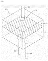
- FIG. 4 is a perspective view illustrating a coolant recovery portion in FIG. 1 .
- a solid line represents a flow of a coolant and a broken line represents a flow of a coolant in a vapor state.
- a selective catalytic reduction system may include a reducing agent injection module 60 configured to inject a reducing agent into an exhaust pipe 40 in order to reduce NOx emissions in an exhaust gas from an engine 10, a selective catalyst reduction (SCR) device 52 configured to catalytically react the reducing agent with the nitrogen oxide in the exhaust gas, and a cooling device for cooling the reducing agent injection module 60.
- a reducing agent injection module 60 configured to inject a reducing agent into an exhaust pipe 40 in order to reduce NOx emissions in an exhaust gas from an engine 10
- SCR selective catalyst reduction
- a fuel gas may be injected into the engine 10 and the engine 10 may operate, and the exhaust gas from the engine 10 may be exhausted through the exhaust pipe 40.
- the fuel gas may be supplied by a fuel supply (not illustrated), may be mixed with an air, which is supplied through a turbocharger 20, in a mixer 16, and then, may be supplied into a combustion chamber of the engine via an intake manifold 12.
- the air flowing from the turbocharger 20 to the engine 10 may be cooled by an intercooler 22.
- some of the exhaust gas exhausted from the combustion chamber through the exhaust pipe 40 may be recirculated to be mixed in the mixer 16 through an exhaust recirculation line (not illustrated) and then may be supplied to the intake manifold 12.
- a coolant discharged from a coolant pump 80 may cool the engine 10.
- the coolant may be a fluid having excellent heat transfer properties.
- a thermostat 82 may detect a temperature of the coolant heated by the engine 10, and an electronic control unit (ECU) may control the coolant pump 80 based on the detected temperature information. While the coolant heated by the engine 10 flows through a radiator 30, the coolant may be cooled by the heat transfer with the outside air.
- the exhaust gas discharged through an exhaust manifold 14 of the engine 10 may flow through the turbocharger 20 and may be exhausted to a surrounding environment via the exhaust pipe 40.
- the reducing agent injection module 60 may be installed in front of the selective catalyst reduction device 52 and may spray a reducing agent such as urea into the exhaust pipe 40 to reduce the nitrogen oxide in the exhaust gas exhausted from the engine 10.
- a reducing agent such as urea
- 'being in front of' means being relatively more near the engine 10 along a flow (F) of the exhaust gas exhausted from the engine 10.
- the reducing agent may be injected into the exhaust pipe 40 and then be vaporized immediately.
- the vaporized reducing agent may be mixed with the exhaust gas, and the nitrogen oxide may catalytically react with the reducing agent in the selective catalyst reduction device 52 such that the nitrogen oxide is reduced into a nitrogen gas and water which are harmless to humans.
- the selective catalyst reduction device 52 may be installed in rear of the reducing agent injection module 60 within the exhaust pipe 40, and may reduce the nitrogen oxide into harmless nitrogen (N 2 ) by Reaction Equations 1 to 3.
- 'being in rear of' means being relatively farther away from the engine 10 along the flow (F) of the exhaust gas exhausted from the engine 10.
- Urea ((NH 2 ) 2 CO) supplied from the reducing agent injection module 60 may generate ammonia (NH 3 ) by hydrolysis.
- the generated ammonia may reduce NO and NO 2 , and convert into harmless nitrogen gas (N 2 ).
- the selective catalyst reduction device 52 may include a carrier (not illustrated) having a plurality of passages.
- the carrier may have a plurality of the passages extending in an axial direction, to increase a contact area with the exhaust gas.
- the carrier may be formed by extrusion of a ceramic raw material to have a honeycomb shape.
- the carrier may be cordierite, silicon carbide fecalloy, NiCrAl, NiFeCrAl, etc.
- the carrier may be formed of metal to have a porous structure.
- the carrier may be formed to have a metal fiber structure with a matrix of metal fibers, or a metal foam with numerous pores.
- the selective catalytic reduction system may further an ammonia slip catalyst device (not illustrated) which is installed in rear of the selective catalytic reduction device 52 to remove ammonia from the exhaust gas.
- an ammonia slip catalyst device (not illustrated) which is installed in rear of the selective catalytic reduction device 52 to remove ammonia from the exhaust gas.
- ammonia generated by the reducing agent injected by the reducing agent injection module 60 to reduce nitride oxide in the exhaust gas may be supplied to maximize the reduction efficiency of nitrogen oxide.
- ammonia slip ammonia unreacted during the catalyst reaction, referred to as ammonia slip, may be released into the atmosphere, causing air pollution.
- the ammonia slip catalyst device may remove the residual ammonia to prevent the ammonia slip.
- the selective catalytic reduction system may further include a mixing device (not illustrated) between the reducing agent injection module 60 and the selective catalytic reduction device 52.
- the mixing device may mix gently the reducing agent injected from the reducing agent injection module 60 and the exhaust gas to increase reduction efficiency of nitrogen oxide of the selective catalytic reduction device 52.
- the mixing device may be omitted as needed.
- the selective catalytic reduction system may further a diesel oxidation catalyst (DOC) device 50 provided in front of the selective catalytic reduction device 52 in the exhaust pipe 40.
- DOC diesel oxidation catalyst
- the diesel oxidation catalyst device 50 may purify carbon monoxide, hydrocarbon, soluble organic fraction, etc.
- the cooling device for the reducing agent injection module may include a coolant supply line 92 connected to an inlet portion 64 of the reducing agent injection module 60 to supply the coolant discharged from the coolant pump 80 to a module cooling channel 62 of the reducing agent injection module 60, a first coolant recovery line 94 connected to an outlet portion 66 of the reducing agent injection module 60, a coolant recovery portion 70 connected to the first coolant recovery line 94, a second coolant recovery line 96 connecting the coolant recovery portion 70 and the coolant pump 80, a vapor discharge line 100 to discharge a coolant in vapor state from the coolant recovery portion 70, and a vapor storage portion 32 connected to the vapor discharge line 100 to store the coolant in vapor state and exhaust the coolant in vapor state to a surrounding environment.
- the coolant supply line, the first coolant recovery line, the second coolant recovery line and the vapor discharge line may include a hose, a pipe, etc.
- one coolant pump 80 may be used to cool the reducing agent injection module 60, the engine 10, the turbocharger 20, etc.
- the coolant supply line 92, the first coolant recovery line 94 and the second coolant recovery line 96 may constitute a coolant circulation line 90.
- the cooling device of the reducing agent injection module may circulate the coolant through the coolant circulation line 90 to prevent the temperature of the reducing agent injection module 60 from being increased by the hot exhaust gas.
- the coolant discharged from the coolant pump 80 may circulate along the coolant circulation line 90 in a circulation direction F to cool the reducing agent injection module 60.
- the coolant discharged from the coolant pump 80 may be supplied to the inlet portion 64 of the reducing agent injection module 60 through the coolant supply line 92. Then, the coolant may flow through the module cooling channel 62 to cool the reducing agent injection module 60 by heat transfer, and then, may be discharged through the outlet portion 66.
- the discharged coolant may be stored temporarily in the coolant recovery portion 70 through the first coolant recovery line 94, and then, may be recovered to the coolant pump 80 through the second coolant recovery line 96.
- the coolant recovery portion 70 may be installed between the reducing agent injection module 60 and the coolant pump 80.
- the coolant recovery portion 70 may be connected to the reducing agent injection module 60 by the first coolant recovery line 94 and may be connected to the coolant pump 80 by the second coolant recovery line 96.
- the coolant recovery portion 70 may be installed higher than the reducing agent injection module 60 along a gravitational direction.
- the coolant vaporized in the module cooling channel 62 of the reducing agent injection module 60 may be floated by a difference of a specific gravity and then recovered in the coolant recovery portion 70, even when the engine stops.
- the coolant flowing through the module cooling channel 62 of the reducing agent injection module 60 may be heated by heat transfer with the exhaust gas. Because the coolant circulates through the coolant circulation line 90 while the coolant pump 80 operates, the coolant flowing through the module cooling channel 62 may not be heated to an evaporating temperature.
- the coolant pump 80 stops, that is, the engine 10 cuts off, the coolant may not circulate to be stationary within the module cooling channel 62.
- heat from the exhaust pipe 40 may be transferred to the reducing agent injection module 60, and thus, the coolant within the module cooling channel 62 may be vaporized to be phase changed into vapor state.
- the coolant recovery portion 70 is positioned higher than the reducing agent injection module 60 along the gravitation direction, the coolant in vapor state within the reducing agent injection module 60 may rise up to move to the coolant recovery portion 70 and the coolant in liquid state having the same volume as the coolant in vapor state may flow into the module cooling channel 62 through the inlet portion 64 due to the specific gravity. That is, after the coolant pump 80 stops, the coolant in liquid state may be replenished due to the rise up of the coolant in vapor state, to cool the reducing agent injection module 60.
- a coolant in liquid state L and a coolant in vapor state V may be received in the coolant recovery portion 70.
- the coolant in liquid state L may be received in a lower portion of the coolant recovery portion 70, and the coolant in liquid state L may flow in the coolant recovery portion 70 through the first coolant recovery line 94 and may be discharged to the coolant pump 80 through the second coolant recovery line 96.
- the coolant in vapor state V may be received in an upper portion of the coolant recovery portion 70, and the coolant in vapor state V may move in the coolant recovery portion 70 through the first coolant recovery line 94 and may be discharged to the vapor storage portion 32 through the vapor discharge line 100 connected to a vapor discharge outlet 72.
- the vapor discharge outlet 72 in an top surface of the coolant recovery portion 70 is illustrated, however, it may not be limited thereto, for example, the vapor discharge outlet 72 may be disposed in the upper portion of the coolant recovery portion 70 or may be connected to the upper portion of the coolant recovery portion 70 through a pipe/hose.
- the vapor storage portion 32 may be installed over the radiator 30 in the gravitational direction, to store a coolant in vapor state. That is, the vapor storage portion 32 may store a coolant in vapor state generated in the radiator 30 and a coolant in vapor state discharged from the coolant recovery portion 70 through the vapor discharge line 100.
- the coolant may be cooled by heat transfer with the outside air while flowing through the radiator 30. However, when the cooling process on the coolant is poor, the coolant may be vaporized to be phase changed into vapor state.
- the coolant in vapor state having a relatively high temperature may not cool sufficiently the engine 10, thereby causing damages on the engine 10.
- the vapor storage portion 32 may remove the coolant in vapor state existing in the coolant circulation line 90, to thereby prevent thermal damages on the engine 10 and the reducing agent injection module 60.
- the vapor storage portion may include a surge tank.
- the vapor storage portion 32 may further include a vapor exhaust cap 34 for exhausting the coolant in vapor state to the outside.
- the vapor exhaust cap may be a pressurized valve which is opened when a pressure of the vapor storage portion is greater than a predetermined pressure.
- the coolant in vapor state may be exhausted from the vapor storage portion 32.
- the configuration of the vapor exhaust cap 34 may not be limited thereto, and, for example, the vapor exhaust cap may be installed in the vapor discharge outlet 72. In this configuration, the coolant recovery portion 70 may not be connected to the vapor storage portion 32, and only the coolant recovery portion 70 may be used to exhaust the coolant in vapor state.
- the coolant may circulate through the coolant circulation line 90 to cool the reducing agent injection module 60.
- the coolant pump 80 stops the coolant in vapor state undergoes natural convection toward the coolant recovery portion 70 to cool the reducing agent injection module 60.
- the coolant in vapor state may be removed through the vapor discharge outlet 72 in the coolant recovery portion 70, and thus, the thermal damages due to the coolant in vapor state may be prevented.
- FIG. 5 is a view illustrating an engine cooling system in accordance with example embodiments.
- the engine cooling system may be substantially the same as or similar to the selective catalytic reduction system as described with reference to FIG. 1 , except for a connection relationship between a coolant recovery portion and a vapor storage portion.
- same reference numerals will be used to refer to the same or like elements and any further repetitive explanation concerning the above elements will be omitted.
- an engine cooling system may include an engine coolant circulation line for circulating a coolant for cooling an engine 10, a coolant pump 80 installed in the engine coolant circulation line to forcibly circulate the coolant, and a radiator 30 installed in the engine coolant circulation line to cool the coolant.
- the engine coolant circulation line may include an engine coolant supply line 83 for supplying the coolant to the coolant pump 80 and an engine coolant recovery line 85 for recovering the coolant discharged from the coolant pump 80 again to the coolant pump 80.
- the radiator 30 may be installed between the engine coolant supply line 83 and the engine coolant recovery line 85.
- a coolant supply line 92 connected to a module cooling channel of a reducing agent injection module 60 may be connected to the engine coolant recovery line 85, and a coolant recovery line 94, 96, 98 connected to the module cooling channel of the reducing agent injection module 60 may be connected to the engine coolant supply line 83.
- the coolant recovery line may include a first coolant recovery line 94, a second coolant recovery line 96 and a third coolant recovery line 98.
- the first coolant recovery line 94 may connect the module cooling channel and a coolant recovery portion 70.
- the second coolant recovery line 96 may connect the coolant recovery portion 70 and a vapor storage portion 32.
- the third coolant recovery line 98 may connect the vapor storage portion 32 to the engine coolant supply line 83.
- the second and the third coolant recovery lines 96, 98 may connect the coolant recovery portion 70 and the engine coolant supply line 83.
- the coolant supply line 92 may branch off from the engine coolant recovery line 85, and the third coolant recovery line 98 of the coolant recovery line may branch off from the engine coolant supply line 83. Accordingly, discharge efficiency may be improved due to an operation of the coolant pump 80.
- the coolant supply line 92 may be connected to the engine coolant recovery line 85 upstream of a thermostat 82 and the radiator 30, to provide a coolant control of the engine cooling system in consideration of the cooling efficiency of the reducing agent injection module 60.
- the connection relationship between the engine coolant circulation line and the coolant circulation line 90 may not be limited thereto.
- the coolant supply line 92 may be connected to the engine coolant supply line 83 downstream of the coolant pump 80, and the coolant recovery line 94, 96, 98 may be connected to the engine coolant recovery line 85 upstream of the thermostat 82.
- 'upstream of an element' represents a location prior to the element along a flow of the coolant
- 'downstream of an element' represents a location past the element along the flow of the coolant.
- the coolant discharged from the module cooling channel 62 may be exhausted through the coolant recovery portion 70 and the vapor storage portion 32 by the second and third coolant recovery lines 96, 98. That is, the vapor storage portion 32 may be used as a part of the coolant recovery line.
- the coolant when the engine operates, the coolant may be circulated through the vapor storage portion 32, and when the engine stops, the coolant in vapor state of the module cooling channel 62 may move sequentially through the coolant recovery portion 70 and the vapor storage portion 32 and then may be exhausted.
- the coolant recovery portion 70 and the vapor storage portion 32 may be installed higher than the module cooling channel 62 along a gravitational direction, and the second coolant recovery line 96 may be installed higher than the first coolant recovery line 96 along the gravitational direction.
- FIG. 6 is a view illustrating an engine cooling system in accordance with example embodiments.
- the engine cooling system may be substantially the same as or similar to the selective catalytic reduction system as described with reference to FIG. 1 , except that a vapor storage portion is connected to a radiator.
- same reference numerals will be used to refer to the same or like elements and any further repetitive explanation concerning the above elements will be omitted.
- a coolant recovery portion 170 having a function of the vapor storage portion 32 in FIG. 1 may be provided. According to this configuration, complexity and cost increase for both of the vapor storage portion and the coolant recovery portion may be prevented.
- a coolant in vapor state generated in a module cooling channel 62 may be exhausted to the outside through a first coolant recovery line 94 and a coolant recovery portion 170, and a coolant in liquid state in the coolant recovery portion 170 may be supplied to an engine coolant supply line 83 through a second coolant recovery line 98.
Landscapes
- Engineering & Computer Science (AREA)
- Chemical & Material Sciences (AREA)
- Combustion & Propulsion (AREA)
- Mechanical Engineering (AREA)
- General Engineering & Computer Science (AREA)
- Chemical Kinetics & Catalysis (AREA)
- Health & Medical Sciences (AREA)
- Toxicology (AREA)
- Exhaust Gas After Treatment (AREA)
Abstract
Description
- The present invention relates to a coolant circulation system for a reducing agent injection module and a selective catalytic reduction system including the same, more particularly, to a cooling device of a reducing agent injection module for an exhaust gas after-treatment and an engine cooling system including the same.
- A diesel engine using compression-ignition combustion has advantages such as a high expansion ratio, but has disadvantages such as vibrations, emissions of pollutants including nitrogen oxide (NOx) and dust or the like. Thus, in order to meet increasingly stringent exhaust gas regulation, an exhaust gas after-treatment device including a selective catalytic reduction (SCR) device may be provided.
- A reducing agent injection module may be installed in front of the selective catalytic reduction device to inject a reducing agent such as urea toward a flow direction of an exhaust gas. The selective catalytic reduction device may react catalytically the reducing agent with nitrogen oxide (NOx) of the exhaust gas such that the nitrogen oxide is reduced into a nitrogen gas and water. Here, as the reducing agent injection module is exposed to the exhaust gas of high temperature, an engine coolant may circulate through a coolant circulation line connected to the reducing agent injection module to prevent thermal damages on the reducing agent injection module.
- However, as an engine stops, a coolant pump may stop to operate so that the flow of the coolant through the coolant circulation line is stopped. In this time, the reducing agent injection module may continue to be heated by the exhaust gas of high temperature, and thus, the reducing agent injection module may be deformed due to the heat or a nozzle of the reducing agent injection module may be blocked by a solid material vaporized from urea.
- An object of the present invention provides a cooling device of a reducing agent injection module having low-cost and improved cooling performances.
- Another object of the present invention provides an engine cooling system including the above-mentioned cooling device of a reducing agent injection module.
- According to example embodiments, a cooling device for a reducing agent injection module, includes a reducing agent injection module installed in an exhaust pipe to inject a reducing agent into the exhaust pipe and having a module cooling channel therein through which a coolant flows to cool the reducing agent injection module, a coolant pump configured to supply the coolant to the module cooling channel, a coolant circulation line including a coolant supply line and a coolant recovery line to connect the coolant pump and the module cooling channel, and a coolant recovery portion installed in the coolant recovery line to store the coolant flowing through the reducing agent injection module and positioned higher than the reducing agent injection module along a gravitational direction. The coolant recovery portion includes a vapor discharge outlet which is connected to an upper portion of the coolant recovery portion to discharge the coolant in vapor state in the coolant recovery portion.
- In example embodiments, the coolant recovery portion may further include a vapor exhaust cap connected to the vapor discharge outlet, and when a vapor pressure in the vapor discharge outlet is greater than a predetermined pressure, the coolant in vapor state may be exhausted through the vapor exhaust cap to a surrounding environment.
- In example embodiments, the cooling device for a reducing agent injection module may further include a vapor discharge line connected to the vapor exhaust outlet and a vapor storage portion connected to the vapor discharge line to store the coolant in vapor state discharged through the vapor exhaust outlet.
- In example embodiments, the cooling device for a reducing agent injection module may further include a radiator configured to cool the coolant flowing through the coolant circulation line. The vapor storage portion may be installed over the radiator to store a coolant in vapor state generated in the radiator.
- In example embodiments, the vapor storage portion may further include a vapor exhaust cap, and wherein when a vapor pressure within the vapor storage portion is greater than a predetermined pressure, the coolant in vapor state may be exhausted through the vapor exhaust cap to a surrounding environment.
- In example embodiments, the coolant recovery line may include a first coolant recovery line connecting the module cooling channel and the coolant recovery portion and a second coolant recovery line connecting the coolant recovery portion and the coolant pump.
- According to example embodiments, an engine cooling system includes a selective catalytic reduction device installed in an exhaust pipe through which an exhaust gas from an engine is exhausted and configured to reduce a nitrogen oxide in the exhaust gas, a reducing agent injection module connected to the exhaust pipe to inject a reducing agent into the exhaust pipe upstream of the selective catalytic reduction device and having a module cooling channel therein, a coolant circulation line including a coolant supply line for supplying a coolant to the module cooling channel and a coolant recovery line for recovering the coolant heated in the module cooling channel, and a coolant recovery portion installed higher than the reducing agent injection module along a gravitational direction to store the coolant discharged through the coolant recovery line and including a vapor discharge outlet for discharging the coolant in vapor state.
- In example embodiments, the engine cooling system may further include a vapor discharge line connected to the vapor exhaust outlet and a vapor storage portion connected to the vapor discharge line to store the coolant in vapor state discharged through the vapor exhaust outlet.
- In example embodiments, the engine cooling system may further include a radiator configured to cool the coolant flowing through the coolant circulation line. The vapor storage portion may be installed over the radiator to store a coolant in vapor state generated in the radiator.
- In example embodiments, the vapor storage portion may further include a vapor exhaust cap, and when a vapor pressure within the vapor storage portion is greater than a predetermined pressure, the coolant in vapor state may be exhausted through the vapor exhaust cap to a surrounding environment.
- In example embodiments, the engine cooling system may further include a coolant pump configured to forcibly circulate the coolant through the coolant circulation line, and the coolant recovery line may include a first coolant recovery line connecting the module cooling channel and the coolant recovery portion and a second coolant recovery line connecting the coolant recovery portion and the coolant pump.
- In example embodiments, the coolant in liquid state and the coolant in vapor state in the module cooling channel may move to the coolant recovery portion through the first coolant recovery line, and the coolant in liquid state in the coolant recovery portion may move to the coolant pump through the second coolant recovery line.
- In example embodiments, the engine cooling system may further include an engine coolant circulation line to circulate the coolant for cooling an engine and including an engine coolant supply line and an engine coolant recovery line, a coolant pump installed in the engine coolant circulation line to forcibly circulate the coolant, a radiator configured to cool the coolant flowing through the engine coolant recovery line and to supply the coolant to the engine coolant supply line, and a vapor storage portion positioned over the radiator along the gravitational direction to store the coolant in vapor state discharged from the radiator. The coolant supply line and the coolant recovery line may be connected to the engine coolant circulation line such that at least a portion of the coolant circulating through the engine coolant circulation line is supplied to the module cooling channel, and the vapor storage portion may be connected to the vapor discharge outlet through a vapor discharge line to store the coolant in vapor state discharged from the engine coolant circulation line and the module cooling channel respectively.
- In example embodiments, the vapor storage portion may further include a vapor exhaust cap, and when a vapor pressure within the vapor storage portion is greater than a predetermined pressure, the coolant in vapor state may be exhausted through the vapor exhaust cap to a surrounding environment.
- In example embodiments, the coolant supply line may branch off from the engine coolant recovery line and the coolant recovery line may branch off from the engine coolant supply line, and wherein a branch point of the engine coolant supply line and the coolant recovery line may be positioned upstream of the coolant pump along the engine coolant supply line.
- In example embodiments, the engine cooling system may further include an engine coolant circulation line to circulate the coolant for cooling an engine and including an engine coolant supply line and an engine coolant recovery line, a coolant pump installed in the engine coolant circulation line to forcibly circulate the coolant, and a radiator configured to cool the coolant flowing through the engine coolant recovery line and to supply the coolant to the engine coolant supply line. The coolant recovery portion may be positioned over the radiator along the gravitational direction and the coolant recovery portion may be connected with the radiator to store the coolant in vapor state discharged from the radiator and the coolant discharged from the module cooling channel. The coolant supply line and the coolant recovery line may be connected to the engine coolant circulation line such that at least a portion of the coolant circulating through the engine coolant circulation line is supplied to the module cooling channel. The coolant supply line may be connected to the engine coolant circulation line and the coolant recovery line may be connected to the engine coolant circulation line via the coolant recovery portion such that at least a portion of the coolant circulating through the engine circulation line is supplied to the module cooling channel.
- In example embodiments, the coolant recovery portion may further include a vapor exhaust cap connected to the vapor discharge outlet, and when a vapor pressure in the vapor discharge outlet is greater than a predetermined pressure, the coolant in vapor state may be exhausted through the vapor exhaust cap to a surrounding environment.
- According to example embodiments, when a coolant pump operates, a coolant may circulate through a coolant circulation line to cool a reducing agent injection module. When the coolant pump stops, a coolant in vapor state may be exhausted and a new coolant in liquid may be replenished, to cool the reducing agent injection module. In here, the coolant in vapor state may be removed through a vapor discharge outlet provided in a coolant recovery portion, to thereby prevent thermal damages on the reducing agent injection module.
- However, the effect of the invention may not be limited thereto, and may be expanded without being deviated from the concept and the scope of the present invention.
-
- FIG. 1 is a view illustrating a selective catalytic reduction system in accordance with example embodiments.
- FIG. 2 is a block diagram illustrating the selective catalytic reduction system of
FIG. 1 . - FIG. 3 is a cross-sectional view illustrating a cooling device of a reducing agent injection module in
FIG. 1 . - FIG. 4 is a perspective view illustrating a coolant recovery portion in
FIG. 1 . - FIG. 5 is a view illustrating an engine cooling system in accordance with example embodiments.
- FIG. 6 is a view illustrating an engine cooling system in accordance with example embodiments.
- Various example embodiments will be described more fully hereinafter with reference to the accompanying drawings, in which example embodiments are shown. Example embodiments may, however, be embodied in many different forms and should not be construed as limited to example embodiments set forth herein. Rather, these example embodiments are provided so that this disclosure will be thorough and complete, and will fully convey the scope of example embodiments to those skilled in the art. In the drawings, the sizes and relative sizes of components or elements may be exaggerated for clarity.
- It will be understood that when an element or layer is referred to as being "on," "connected to" or "coupled to" another element or layer, it can be directly on, connected or coupled to the other element or layer or intervening elements or layers may be present. In contrast, when an element or layer is referred to as being "directly on," "directly connected to" or "directly coupled to" another element or layer, there are no intervening elements or layers present. Like numerals refer to like elements throughout. As used herein, the term "and/or" includes any and all combinations of one or more of the associated listed items.
- It will be understood that, although the terms first, second, third, etc. may be used herein to describe various elements, components, regions, layers and/or sections, these elements, components, regions, layers and/or sections should not be limited by these terms. These terms are only used to distinguish one element, component, region, layer or section from another element, component, region, layer or section. Thus, a first element, component, region, layer or section discussed below could be termed a second element, component, region, layer or section without departing from the teachings of example embodiments.
- Spatially relative terms, such as "beneath," "below," "lower," "above," "upper" and the like, may be used herein for ease of description to describe one element or feature's relationship to another element(s) or feature(s) as illustrated in the figures. It will be understood that the spatially relative terms are intended to encompass different orientations of the device in use or operation in addition to the orientation depicted in the figures. For example, if the device in the figures is turned over, elements described as "below" or "beneath" other elements or features would then be oriented "above" the other elements or features. Thus, the exemplary term "below" can encompass both an orientation of above and below. The device may be otherwise oriented (rotated 90 degrees or at other orientations) and the spatially relative descriptors used herein interpreted accordingly.
- The terminology used herein is for the purpose of describing particular example embodiments only and is not intended to be limiting of example embodiments. As used herein, the singular forms "a," "an" and "the" are intended to include the plural forms as well, unless the context clearly indicates otherwise. It will be further understood that the terms "comprises" and/or "comprising," when used in this specification, specify the presence of stated features, integers, steps, operations, elements, and/or components, but do not preclude the presence or addition of one or more other features, integers, steps, operations, elements, components, and/or groups thereof.
- Unless otherwise defined, all terms (including technical and scientific terms) used herein have the same meaning as commonly understood by one of ordinary skill in the art to which example embodiments belong. It will be further understood that terms, such as those defined in commonly used dictionaries, should be interpreted as having a meaning that is consistent with their meaning in the context of the relevant art and will not be interpreted in an idealized or overly formal sense unless expressly so defined herein.
- Hereinafter, preferable embodiments of the present invention will be explained in detail with reference to the accompanying drawings. Like numerals refer to like elements throughout example embodiments, and any further repetitive explanation concerning the similar elements will be omitted.
-
FIG. 1 is a view illustrating a selective catalytic reduction system in accordance with example embodiments.FIG. 2 is a block diagram illustrating the selective catalytic reduction system ofFIG. 1 .FIG. 3 is a cross-sectional view illustrating a cooling device of a reducing agent injection module inFIG. 1 .FIG. 4 is a perspective view illustrating a coolant recovery portion inFIG. 1 . InFIGS. 1 and2 , a solid line represents a flow of a coolant and a broken line represents a flow of a coolant in a vapor state. - Referring to
FIGS. 1 to 4 , a selective catalytic reduction system may include a reducingagent injection module 60 configured to inject a reducing agent into anexhaust pipe 40 in order to reduce NOx emissions in an exhaust gas from anengine 10, a selective catalyst reduction (SCR)device 52 configured to catalytically react the reducing agent with the nitrogen oxide in the exhaust gas, and a cooling device for cooling the reducingagent injection module 60. - As illustrated in
FIG. 1 , a fuel gas may be injected into theengine 10 and theengine 10 may operate, and the exhaust gas from theengine 10 may be exhausted through theexhaust pipe 40. - In particular, the fuel gas may be supplied by a fuel supply (not illustrated), may be mixed with an air, which is supplied through a
turbocharger 20, in amixer 16, and then, may be supplied into a combustion chamber of the engine via anintake manifold 12. In here, the air flowing from theturbocharger 20 to theengine 10 may be cooled by anintercooler 22. Additionally, some of the exhaust gas exhausted from the combustion chamber through theexhaust pipe 40 may be recirculated to be mixed in themixer 16 through an exhaust recirculation line (not illustrated) and then may be supplied to theintake manifold 12. - A coolant discharged from a
coolant pump 80 may cool theengine 10. The coolant may be a fluid having excellent heat transfer properties. Athermostat 82 may detect a temperature of the coolant heated by theengine 10, and an electronic control unit (ECU) may control thecoolant pump 80 based on the detected temperature information. While the coolant heated by theengine 10 flows through aradiator 30, the coolant may be cooled by the heat transfer with the outside air. On the other hand, the exhaust gas discharged through an exhaust manifold 14 of theengine 10 may flow through theturbocharger 20 and may be exhausted to a surrounding environment via theexhaust pipe 40. - The reducing
agent injection module 60 may be installed in front of the selectivecatalyst reduction device 52 and may spray a reducing agent such as urea into theexhaust pipe 40 to reduce the nitrogen oxide in the exhaust gas exhausted from theengine 10. In here, 'being in front of' means being relatively more near theengine 10 along a flow (F) of the exhaust gas exhausted from theengine 10. - Because the temperature of the exhaust gas from the
engine 10 ranges as high as several hundreds of degrees (°C), the reducing agent may be injected into theexhaust pipe 40 and then be vaporized immediately. The vaporized reducing agent may be mixed with the exhaust gas, and the nitrogen oxide may catalytically react with the reducing agent in the selectivecatalyst reduction device 52 such that the nitrogen oxide is reduced into a nitrogen gas and water which are harmless to humans. - The selective
catalyst reduction device 52 may be installed in rear of the reducingagent injection module 60 within theexhaust pipe 40, and may reduce the nitrogen oxide into harmless nitrogen (N2) by Reaction Equations 1 to 3. In here, 'being in rear of' means being relatively farther away from theengine 10 along the flow (F) of the exhaust gas exhausted from theengine 10.
[Reaction Equation 1] (NH 2)2 CO+H 2 O→CO 2+2NH 3
[Reaction Equation 2] 4NO+4NH 3+O 2→4N 2+6H 2O
[Reaction Equation 3] 6NO 2+8NH 3→7N 2+12H 2 O
- Urea ((NH2)2CO) supplied from the reducing
agent injection module 60 may generate ammonia (NH3) by hydrolysis. The generated ammonia may reduce NO and NO2, and convert into harmless nitrogen gas (N2). - In example embodiments, the selective
catalyst reduction device 52 may include a carrier (not illustrated) having a plurality of passages. The carrier may have a plurality of the passages extending in an axial direction, to increase a contact area with the exhaust gas. - For example, the carrier may be formed by extrusion of a ceramic raw material to have a honeycomb shape. Examples of the carrier may be cordierite, silicon carbide fecalloy, NiCrAl, NiFeCrAl, etc. Alternatively, the carrier may be formed of metal to have a porous structure. For example, the carrier may be formed to have a metal fiber structure with a matrix of metal fibers, or a metal foam with numerous pores.
- In example embodiments, the selective catalytic reduction system may further an ammonia slip catalyst device (not illustrated) which is installed in rear of the selective
catalytic reduction device 52 to remove ammonia from the exhaust gas. - The ammonia generated by the reducing agent injected by the reducing
agent injection module 60 to reduce nitride oxide in the exhaust gas. In here, more ammonia than a stoichiometric amount may be supplied to maximize the reduction efficiency of nitrogen oxide. Thus, ammonia unreacted during the catalyst reaction, referred to as ammonia slip, may be released into the atmosphere, causing air pollution. The ammonia slip catalyst device may remove the residual ammonia to prevent the ammonia slip. - In example embodiments, the selective catalytic reduction system may further include a mixing device (not illustrated) between the reducing
agent injection module 60 and the selectivecatalytic reduction device 52. The mixing device may mix gently the reducing agent injected from the reducingagent injection module 60 and the exhaust gas to increase reduction efficiency of nitrogen oxide of the selectivecatalytic reduction device 52. The mixing device may be omitted as needed. - In example embodiments, the selective catalytic reduction system may further a diesel oxidation catalyst (DOC)
device 50 provided in front of the selectivecatalytic reduction device 52 in theexhaust pipe 40. The dieseloxidation catalyst device 50 may purify carbon monoxide, hydrocarbon, soluble organic fraction, etc. - In example embodiments, the cooling device for the reducing agent injection module may include a
coolant supply line 92 connected to aninlet portion 64 of the reducingagent injection module 60 to supply the coolant discharged from thecoolant pump 80 to amodule cooling channel 62 of the reducingagent injection module 60, a firstcoolant recovery line 94 connected to an outlet portion 66 of the reducingagent injection module 60, acoolant recovery portion 70 connected to the firstcoolant recovery line 94, a secondcoolant recovery line 96 connecting thecoolant recovery portion 70 and thecoolant pump 80, avapor discharge line 100 to discharge a coolant in vapor state from thecoolant recovery portion 70, and avapor storage portion 32 connected to thevapor discharge line 100 to store the coolant in vapor state and exhaust the coolant in vapor state to a surrounding environment. For example, the coolant supply line, the first coolant recovery line, the second coolant recovery line and the vapor discharge line may include a hose, a pipe, etc. - In the cooling device of the reducing agent injection module, one
coolant pump 80 may be used to cool the reducingagent injection module 60, theengine 10, theturbocharger 20, etc. - The
coolant supply line 92, the firstcoolant recovery line 94 and the secondcoolant recovery line 96 may constitute acoolant circulation line 90. When thecoolant pump 80 operates, that is, theengine 10 operates, the cooling device of the reducing agent injection module may circulate the coolant through thecoolant circulation line 90 to prevent the temperature of the reducingagent injection module 60 from being increased by the hot exhaust gas. - As illustrated in
FIG. 3 , the coolant discharged from thecoolant pump 80 may circulate along thecoolant circulation line 90 in a circulation direction F to cool the reducingagent injection module 60. In particular, the coolant discharged from thecoolant pump 80 may be supplied to theinlet portion 64 of the reducingagent injection module 60 through thecoolant supply line 92. Then, the coolant may flow through themodule cooling channel 62 to cool the reducingagent injection module 60 by heat transfer, and then, may be discharged through the outlet portion 66. The discharged coolant may be stored temporarily in thecoolant recovery portion 70 through the firstcoolant recovery line 94, and then, may be recovered to thecoolant pump 80 through the secondcoolant recovery line 96. - The
coolant recovery portion 70 may be installed between the reducingagent injection module 60 and thecoolant pump 80. In particular, thecoolant recovery portion 70 may be connected to the reducingagent injection module 60 by the firstcoolant recovery line 94 and may be connected to thecoolant pump 80 by the secondcoolant recovery line 96. - In example embodiments, the
coolant recovery portion 70 may be installed higher than the reducingagent injection module 60 along a gravitational direction. Thus, the coolant vaporized in themodule cooling channel 62 of the reducingagent injection module 60 may be floated by a difference of a specific gravity and then recovered in thecoolant recovery portion 70, even when the engine stops. - The coolant flowing through the
module cooling channel 62 of the reducingagent injection module 60 may be heated by heat transfer with the exhaust gas. Because the coolant circulates through thecoolant circulation line 90 while thecoolant pump 80 operates, the coolant flowing through themodule cooling channel 62 may not be heated to an evaporating temperature. - On the contrary, when the
coolant pump 80 stops, that is, theengine 10 cuts off, the coolant may not circulate to be stationary within themodule cooling channel 62. In this case, heat from theexhaust pipe 40 may be transferred to the reducingagent injection module 60, and thus, the coolant within themodule cooling channel 62 may be vaporized to be phase changed into vapor state. Since thecoolant recovery portion 70 is positioned higher than the reducingagent injection module 60 along the gravitation direction, the coolant in vapor state within the reducingagent injection module 60 may rise up to move to thecoolant recovery portion 70 and the coolant in liquid state having the same volume as the coolant in vapor state may flow into themodule cooling channel 62 through theinlet portion 64 due to the specific gravity. That is, after thecoolant pump 80 stops, the coolant in liquid state may be replenished due to the rise up of the coolant in vapor state, to cool the reducingagent injection module 60. - As illustrated in
FIG. 4 , a coolant in liquid state L and a coolant in vapor state V may be received in thecoolant recovery portion 70. The coolant in liquid state L may be received in a lower portion of thecoolant recovery portion 70, and the coolant in liquid state L may flow in thecoolant recovery portion 70 through the firstcoolant recovery line 94 and may be discharged to thecoolant pump 80 through the secondcoolant recovery line 96. The coolant in vapor state V may be received in an upper portion of thecoolant recovery portion 70, and the coolant in vapor state V may move in thecoolant recovery portion 70 through the firstcoolant recovery line 94 and may be discharged to thevapor storage portion 32 through thevapor discharge line 100 connected to avapor discharge outlet 72. InFIG. 3 , thevapor discharge outlet 72 in an top surface of thecoolant recovery portion 70 is illustrated, however, it may not be limited thereto, for example, thevapor discharge outlet 72 may be disposed in the upper portion of thecoolant recovery portion 70 or may be connected to the upper portion of thecoolant recovery portion 70 through a pipe/hose. - The
vapor storage portion 32 may be installed over theradiator 30 in the gravitational direction, to store a coolant in vapor state. That is, thevapor storage portion 32 may store a coolant in vapor state generated in theradiator 30 and a coolant in vapor state discharged from thecoolant recovery portion 70 through thevapor discharge line 100. - The coolant may be cooled by heat transfer with the outside air while flowing through the
radiator 30. However, when the cooling process on the coolant is poor, the coolant may be vaporized to be phase changed into vapor state. The coolant in vapor state having a relatively high temperature may not cool sufficiently theengine 10, thereby causing damages on theengine 10. In this case, thevapor storage portion 32 may remove the coolant in vapor state existing in thecoolant circulation line 90, to thereby prevent thermal damages on theengine 10 and the reducingagent injection module 60. For example, the vapor storage portion may include a surge tank. - In example embodiments, the
vapor storage portion 32 may further include avapor exhaust cap 34 for exhausting the coolant in vapor state to the outside. For example, the vapor exhaust cap may be a pressurized valve which is opened when a pressure of the vapor storage portion is greater than a predetermined pressure. When thevapor exhaust cap 34 is opened, the coolant in vapor state may be exhausted from thevapor storage portion 32. The configuration of thevapor exhaust cap 34 may not be limited thereto, and, for example, the vapor exhaust cap may be installed in thevapor discharge outlet 72. In this configuration, thecoolant recovery portion 70 may not be connected to thevapor storage portion 32, and only thecoolant recovery portion 70 may be used to exhaust the coolant in vapor state. - As mentioned above, when the
coolant pump 80 operates, the coolant may circulate through thecoolant circulation line 90 to cool the reducingagent injection module 60. When thecoolant pump 80 stops, the coolant in vapor state undergoes natural convection toward thecoolant recovery portion 70 to cool the reducingagent injection module 60. In here, the coolant in vapor state may be removed through thevapor discharge outlet 72 in thecoolant recovery portion 70, and thus, the thermal damages due to the coolant in vapor state may be prevented. -
FIG. 5 is a view illustrating an engine cooling system in accordance with example embodiments. The engine cooling system may be substantially the same as or similar to the selective catalytic reduction system as described with reference toFIG. 1 , except for a connection relationship between a coolant recovery portion and a vapor storage portion. Thus, same reference numerals will be used to refer to the same or like elements and any further repetitive explanation concerning the above elements will be omitted. - Referring to
FIG. 5 , an engine cooling system may include an engine coolant circulation line for circulating a coolant for cooling anengine 10, acoolant pump 80 installed in the engine coolant circulation line to forcibly circulate the coolant, and aradiator 30 installed in the engine coolant circulation line to cool the coolant. - The engine coolant circulation line may include an engine
coolant supply line 83 for supplying the coolant to thecoolant pump 80 and an enginecoolant recovery line 85 for recovering the coolant discharged from thecoolant pump 80 again to thecoolant pump 80. Theradiator 30 may be installed between the enginecoolant supply line 83 and the enginecoolant recovery line 85. - A
coolant supply line 92 connected to a module cooling channel of a reducingagent injection module 60 may be connected to the enginecoolant recovery line 85, and acoolant recovery line agent injection module 60 may be connected to the enginecoolant supply line 83. - In example embodiments, the coolant recovery line may include a first
coolant recovery line 94, a secondcoolant recovery line 96 and a thirdcoolant recovery line 98. In particular, the firstcoolant recovery line 94 may connect the module cooling channel and acoolant recovery portion 70. The secondcoolant recovery line 96 may connect thecoolant recovery portion 70 and avapor storage portion 32. The thirdcoolant recovery line 98 may connect thevapor storage portion 32 to the enginecoolant supply line 83. Accordingly, the second and the thirdcoolant recovery lines coolant recovery portion 70 and the enginecoolant supply line 83. - The
coolant supply line 92 may branch off from the enginecoolant recovery line 85, and the thirdcoolant recovery line 98 of the coolant recovery line may branch off from the enginecoolant supply line 83. Accordingly, discharge efficiency may be improved due to an operation of thecoolant pump 80. Thecoolant supply line 92 may be connected to the enginecoolant recovery line 85 upstream of athermostat 82 and theradiator 30, to provide a coolant control of the engine cooling system in consideration of the cooling efficiency of the reducingagent injection module 60. - The connection relationship between the engine coolant circulation line and the
coolant circulation line 90 may not be limited thereto. Thecoolant supply line 92 may be connected to the enginecoolant supply line 83 downstream of thecoolant pump 80, and thecoolant recovery line coolant recovery line 85 upstream of thethermostat 82. In here, 'upstream of an element' represents a location prior to the element along a flow of the coolant, and 'downstream of an element' represents a location past the element along the flow of the coolant. - The coolant discharged from the
module cooling channel 62 may be exhausted through thecoolant recovery portion 70 and thevapor storage portion 32 by the second and thirdcoolant recovery lines vapor storage portion 32 may be used as a part of the coolant recovery line. In this case, when the engine operates, the coolant may be circulated through thevapor storage portion 32, and when the engine stops, the coolant in vapor state of themodule cooling channel 62 may move sequentially through thecoolant recovery portion 70 and thevapor storage portion 32 and then may be exhausted. Thecoolant recovery portion 70 and thevapor storage portion 32 may be installed higher than themodule cooling channel 62 along a gravitational direction, and the secondcoolant recovery line 96 may be installed higher than the firstcoolant recovery line 96 along the gravitational direction. -
FIG. 6 is a view illustrating an engine cooling system in accordance with example embodiments. The engine cooling system may be substantially the same as or similar to the selective catalytic reduction system as described with reference toFIG. 1 , except that a vapor storage portion is connected to a radiator. Thus, same reference numerals will be used to refer to the same or like elements and any further repetitive explanation concerning the above elements will be omitted. - Referring to
FIG. 6 , acoolant recovery portion 170 having a function of thevapor storage portion 32 inFIG. 1 may be provided. According to this configuration, complexity and cost increase for both of the vapor storage portion and the coolant recovery portion may be prevented. A coolant in vapor state generated in amodule cooling channel 62 may be exhausted to the outside through a firstcoolant recovery line 94 and acoolant recovery portion 170, and a coolant in liquid state in thecoolant recovery portion 170 may be supplied to an enginecoolant supply line 83 through a secondcoolant recovery line 98. - The present invention has been explained with reference to preferable embodiments, however, those skilled in the art may understand that the present invention may be modified or changed without being deviated from the concept and the scope of the present invention disclosed in the following claims.
-
- 10: engine 12: intake manifold
- 14: exhaust manifold 16: mixer
- 20: turbocharger 30: radiator
- 32: vapor storage portion 34: vapor exhaust cap
- 40: exhaust pipe 50: diesel oxidation catalyst
- 52: selective catalytic reduction device 60: reducing agent injection module
- 62: module cooling channel 64: inlet portion
- 66:
outlet portion 70, 170: coolant storage portion - 72: vapor discharge outlet 80: coolant pump
- 82: thermostat 90: coolant circulation line
- 92: coolant supply line 94: first coolant recovery line
- 96: second coolant recovery line 100: vapor discharge line
- L: coolant in liquid state V: coolant in vapor state
- F: circulation direction of coolant
Claims (18)
- A cooling device for a reducing agent injection module, comprising:a reducing agent injection module installed in an exhaust pipe to inject a reducing agent into the exhaust pipe, the reducing agent injection module having a module cooling channel therein through which a coolant flows to cool the reducing agent injection module;a coolant pump configured to supply the coolant to the module cooling channel;a coolant circulation line including a coolant supply line and a coolant recovery line to connect the coolant pump and the module cooling channel; anda coolant recovery portion installed in the coolant recovery line to store the coolant flowing through the reducing agent injection module, and the coolant recovery portion being positioned higher than the reducing agent injection module along a gravitational direction,wherein the coolant recovery portion includes a vapor discharge outlet which is connected to an upper portion of the coolant recovery portion to discharge the coolant in vapor state in the coolant recovery portion.
- The cooling device for a reducing agent injection module of claim 1, wherein the coolant recovery portion further includes a vapor exhaust cap connected to the vapor discharge outlet, and
wherein when a vapor pressure in the vapor discharge outlet is greater than a predetermined pressure, the coolant in vapor state is exhausted through the vapor exhaust cap to a surrounding environment. - The cooling device for a reducing agent injection module of claim 1, further comprising:a vapor discharge line connected to the vapor exhaust outlet; anda vapor storage portion connected to the vapor discharge line to store the coolant in vapor state discharged through the vapor exhaust outlet.
- The cooling device for a reducing agent injection module of claim 3, further comprising a radiator configured to cool the coolant flowing through the coolant circulation line, and
wherein the vapor storage portion is installed over the radiator to store a coolant in vapor state generated in the radiator. - The cooling device for a reducing agent injection module of claim 3, wherein the vapor storage portion further includes a vapor exhaust cap, and
wherein when a vapor pressure within the vapor storage portion is greater than a predetermined pressure, the coolant in vapor state is exhausted through the vapor exhaust cap to a surrounding environment. - The cooling device for a reducing agent injection module of claim 1, wherein the coolant recovery line comprises
a first coolant recovery line connecting the module cooling channel and the coolant recovery portion; and
a second coolant recovery line connecting the coolant recovery portion and the coolant pump. - An engine cooling system, comprising:a selective catalytic reduction device installed in an exhaust pipe through which an exhaust gas from an engine is exhausted and configured to reduce a nitrogen oxide in the exhaust gas;a reducing agent injection module connected to the exhaust pipe to inject a reducing agent into the exhaust pipe upstream of the selective catalytic reduction device, the reducing agent injection module having a module cooling channel therein;a coolant circulation line including a coolant supply line for supplying a coolant to the module cooling channel and a coolant recovery line for recovering the coolant heated in the module cooling channel; anda coolant recovery portion installed higher than the reducing agent injection module along a gravitational direction to store the coolant discharged through the coolant recovery line, the coolant recovery portion including a vapor discharge outlet for discharging the coolant in vapor state.
- The engine cooling system of claim 7, further comprising:a vapor discharge line connected to the vapor exhaust outlet; anda vapor storage portion connected to the vapor discharge line to store the coolant in vapor state discharged through the vapor exhaust outlet.
- The engine cooling system of claim 8, further comprising a radiator configured to cool the coolant flowing through the coolant circulation line, and
wherein the vapor storage portion is installed over the radiator to store a coolant in vapor state generated in the radiator - The engine cooling system of claim 8, wherein the vapor storage portion further includes a vapor exhaust cap, and
wherein when a vapor pressure within the vapor storage portion is greater than a predetermined pressure, the coolant in vapor state is exhausted through the vapor exhaust cap to a surrounding environment. - The engine cooling system of claim 7, further comprising a coolant pump configured to forcibly circulate the coolant through the coolant circulation line, and
wherein the coolant recovery line comprises
a first coolant recovery line connecting the module cooling channel and the coolant recovery portion; and
a second coolant recovery line connecting the coolant recovery portion and the coolant pump. - The engine cooling system of claim 11, wherein the coolant in liquid state and the coolant in vapor state in the module cooling channel move to the coolant recovery portion through the first coolant recovery line, and
the coolant in liquid state in the coolant recovery portion moves to the coolant pump through the second coolant recovery line. - The engine cooling system of claim 7, further comprising:an engine coolant circulation line to circulate the coolant for cooling an engine and including an engine coolant supply line and an engine coolant recovery line;a coolant pump installed in the engine coolant circulation line to forcibly circulate the coolant;a radiator configured to cool the coolant flowing through the engine coolant recovery line and to supply the coolant to the engine coolant supply line; anda vapor storage portion positioned over the radiator along the gravitational direction to store the coolant in vapor state discharged from the radiator,wherein the coolant supply line and the coolant recovery line are connected to the engine coolant circulation line such that at least a portion of the coolant circulating through the engine coolant circulation line is supplied to the module cooling channel, andwherein the vapor storage portion is connected to the vapor discharge outlet through a vapor discharge line to store the coolant in vapor state discharged from the engine coolant circulation line and the module cooling channel respectively.
- The engine cooling system of claim 13, wherein the vapor storage portion further includes a vapor exhaust cap, and
wherein when a vapor pressure within the vapor storage portion is greater than a predetermined pressure, the coolant in vapor state is exhausted through the vapor exhaust cap to a surrounding environment. - The engine cooling system of claim 13, wherein the coolant supply line branches off from the engine coolant recovery line and the coolant recovery line branches off from the engine coolant supply line, and
wherein a branch point of the engine coolant supply line and the coolant recovery line is positioned upstream of the coolant pump along the engine coolant supply line. - The engine cooling system of claim 7, further comprising:an engine coolant circulation line to circulate the coolant for cooling an engine and including an engine coolant supply line and an engine coolant recovery line;a coolant pump installed in the engine coolant circulation line to forcibly circulate the coolant; anda radiator configured to cool the coolant flowing through the engine coolant recovery line and to supply the coolant to the engine coolant supply line,wherein the coolant recovery portion is positioned over the radiator along the gravitational direction and the coolant recovery portion is connected with the radiator to store the coolant in vapor state discharged from the radiator and the coolant discharged from the module cooling channel,wherein the coolant supply line and the coolant recovery line are connected to the engine coolant circulation line such that at least a portion of the coolant circulating through the engine coolant circulation line is supplied to the module cooling channel, andwherein the coolant supply line is connected to the engine coolant circulation line and the coolant recovery line is connected to the engine coolant circulation line via the coolant recovery portion such that at least a portion of the coolant circulating through the engine circulation line is supplied to the module cooling channel.
- The engine cooling system of claim 16, wherein the coolant recovery portion further includes a vapor exhaust cap connected to the vapor discharge outlet, and
wherein when a vapor pressure in the vapor discharge outlet is greater than a predetermined pressure, the coolant in vapor state is exhausted through the vapor exhaust cap to a surrounding environment - The engine cooling system of claim 16, wherein the coolant supply line branches off from the engine coolant recovery line and the coolant recovery line branches off from the engine coolant supply line,
wherein the coolant supply line branches off from the engine coolant recovery line upstream of a thermostat which is installed in the engine coolant recovery line, and
wherein the coolant recovery line is connected to the engine coolant supply line upstream of the coolant pump.
Applications Claiming Priority (2)
| Application Number | Priority Date | Filing Date | Title |
|---|---|---|---|
| KR1020150154896A KR102413070B1 (en) | 2015-11-05 | 2015-11-05 | Cooling device for reducing agent dosing module and engine cooling system having the same |
| PCT/KR2016/012757 WO2017078505A1 (en) | 2015-11-05 | 2016-11-07 | Cooling device for reductant spray module, and selective engine cooling sytem having same |
Publications (3)
| Publication Number | Publication Date |
|---|---|
| EP3369900A1 true EP3369900A1 (en) | 2018-09-05 |
| EP3369900A4 EP3369900A4 (en) | 2019-03-20 |
| EP3369900B1 EP3369900B1 (en) | 2020-05-20 |
Family
ID=58662316
Family Applications (1)
| Application Number | Title | Priority Date | Filing Date |
|---|---|---|---|
| EP16862520.0A Active EP3369900B1 (en) | 2015-11-05 | 2016-11-07 | Cooling device for reductant spray module, and selective engine cooling sytem having same |
Country Status (5)
| Country | Link |
|---|---|
| US (1) | US10550745B2 (en) |
| EP (1) | EP3369900B1 (en) |
| KR (1) | KR102413070B1 (en) |
| CN (1) | CN108350787B (en) |
| WO (1) | WO2017078505A1 (en) |
Families Citing this family (6)
| Publication number | Priority date | Publication date | Assignee | Title |
|---|---|---|---|---|
| KR102335331B1 (en) * | 2017-04-18 | 2021-12-03 | 현대자동차 주식회사 | Fuel Reforming System And Control Method of Coolant Supply |
| KR102322256B1 (en) * | 2017-05-08 | 2021-11-04 | 현대자동차 주식회사 | Fuel Reforming System |
| US20190162107A1 (en) * | 2017-11-28 | 2019-05-30 | Deere & Company | Cooling system for diesel exhaust fluid doser |
| KR102463464B1 (en) * | 2018-05-29 | 2022-11-04 | 현대자동차주식회사 | Dosing injector degassing system |
| CN115075933B (en) * | 2021-03-10 | 2023-11-21 | 现代斗山英维高株式会社 | Double pressure regulating tank |
| KR20230090797A (en) * | 2021-12-15 | 2023-06-22 | 엘에스엠트론 주식회사 | Cooling Device For Reducing Agent Dosing Module |
Family Cites Families (17)
| Publication number | Priority date | Publication date | Assignee | Title |
|---|---|---|---|---|
| JP2659602B2 (en) * | 1990-04-06 | 1997-09-30 | 日野自動車工業株式会社 | Engine cooling system |
| KR960017934U (en) | 1994-11-23 | 1996-06-19 | Coolant Steam Discharge Device for Automobile Radiator | |
| WO2005028827A1 (en) * | 2003-09-19 | 2005-03-31 | Nissan Diesel Motor Co., Ltd. | Exhaust gas clarification apparatus for engine |
| JP2011247135A (en) | 2010-05-25 | 2011-12-08 | Isuzu Motors Ltd | SCR system |
| KR101278574B1 (en) | 2011-07-29 | 2013-06-26 | 자동차부품연구원 | Apparatus for purifying engine exhaust gas and vehicle using the same |
| KR101299970B1 (en) * | 2011-08-18 | 2013-08-27 | 전남대학교산학협력단 | Apparatus for reducing nitrogen oxide and for antiknock in dimethylether fueled vehicles |
| US8635859B2 (en) * | 2011-12-06 | 2014-01-28 | GM Global Technology Operations LLC | System and method for determining a maximum dose rate of reductant |
| JP5873399B2 (en) * | 2012-06-26 | 2016-03-01 | 日野自動車株式会社 | Cooling water circulation device |
| DE112013000161C5 (en) * | 2013-03-15 | 2023-03-16 | Komatsu Ltd. | Exhaust aftertreatment unit and a construction vehicle containing it |
| JP6077114B2 (en) | 2013-06-04 | 2017-02-08 | ボッシュ株式会社 | Reducing agent supply device and exhaust purification system |
| US9267410B2 (en) * | 2014-01-14 | 2016-02-23 | Caterpillar Inc. | Injector cooling apparatus |
| JP6217408B2 (en) | 2014-01-24 | 2017-10-25 | コベルコ建機株式会社 | Exhaust treatment device for construction machine and construction machine |
| WO2015126034A1 (en) | 2014-02-21 | 2015-08-27 | 두산인프라코어 주식회사 | Cooling device of reducing-agent injection module and selective catalyst reduction system having same |
| KR102107656B1 (en) | 2014-02-24 | 2020-05-26 | 두산인프라코어 주식회사 | Coolins device for reducing agent dosing modue and compressed natural gas engine system |
| US20140322088A1 (en) | 2014-07-10 | 2014-10-30 | Perkins Engines Company Limited | Auxiliary coolant tank for exhaust aftertreatment system |
| US20140369899A1 (en) * | 2014-09-01 | 2014-12-18 | Caterpillar Inc. | Multi-compartment phae separation tank for multiple reductant injectors |
| DE202015005776U1 (en) * | 2015-08-14 | 2016-11-15 | GM Global Technology Operations LLC (n. d. Ges. d. Staates Delaware) | Computer program for controlling the temperature of an injector for injecting a reducing agent into an exhaust pipe of an internal combustion engine |
-
2015
- 2015-11-05 KR KR1020150154896A patent/KR102413070B1/en active Active
-
2016
- 2016-11-07 WO PCT/KR2016/012757 patent/WO2017078505A1/en not_active Ceased
- 2016-11-07 EP EP16862520.0A patent/EP3369900B1/en active Active
- 2016-11-07 US US15/774,214 patent/US10550745B2/en active Active
- 2016-11-07 CN CN201680064821.9A patent/CN108350787B/en active Active
Also Published As
| Publication number | Publication date |
|---|---|
| EP3369900B1 (en) | 2020-05-20 |
| WO2017078505A1 (en) | 2017-05-11 |
| US10550745B2 (en) | 2020-02-04 |
| KR102413070B1 (en) | 2022-06-24 |
| CN108350787B (en) | 2020-05-12 |
| US20180328247A1 (en) | 2018-11-15 |
| CN108350787A (en) | 2018-07-31 |
| EP3369900A4 (en) | 2019-03-20 |
| KR20170052861A (en) | 2017-05-15 |
Similar Documents
| Publication | Publication Date | Title |
|---|---|---|
| EP3369900B1 (en) | Cooling device for reductant spray module, and selective engine cooling sytem having same | |
| EP3102801B1 (en) | Exhaust system structure for internal combustion engine | |
| CN101878354B (en) | Exhaust treatment system having a diverter valve | |
| US8844269B2 (en) | Aftertreatment system and method for pre-decomposed reductant solution | |
| EP3732358B1 (en) | A start-up method for a vehicle with a hybrid propulsion system | |
| US11149622B2 (en) | Multiple bank exhaust system comprising reductant supply system arranged upstream of a turbine | |
| US20130000729A1 (en) | Def pump and tank thawing system and method | |
| US20140174696A1 (en) | Injector Cooling Apparatus and Method | |
| US9267410B2 (en) | Injector cooling apparatus | |
| EP1550796B1 (en) | Method for controlling the temperature of the exhaust gases in an engine and the relative engine apparatus | |
| CN204783193U (en) | A exhaust after treatment system for internal -combustion engine | |
| EP3364006A1 (en) | Exhaust gas purification device | |
| KR20180068198A (en) | Reforming system | |
| KR102382254B1 (en) | Exhaust gas treatment system of diesel engine | |
| EP3109427B1 (en) | Cooling device of reducing-agent injection module and selective catalyst reduction system having same | |
| US20130180231A1 (en) | Exhaust aftertreatment system | |
| KR20190072341A (en) | Fuel reforming system | |
| US20100186389A1 (en) | Reductant Insulating System | |
| CN105189956A (en) | Exhaust system for an internal combustion engine of a motor vehicle and method for operating an exhaust system |
Legal Events
| Date | Code | Title | Description |
|---|---|---|---|
| STAA | Information on the status of an ep patent application or granted ep patent |
Free format text: STATUS: THE INTERNATIONAL PUBLICATION HAS BEEN MADE |
|
| PUAI | Public reference made under article 153(3) epc to a published international application that has entered the european phase |
Free format text: ORIGINAL CODE: 0009012 |
|
| STAA | Information on the status of an ep patent application or granted ep patent |
Free format text: STATUS: REQUEST FOR EXAMINATION WAS MADE |
|
| 17P | Request for examination filed |
Effective date: 20180601 |
|
| AK | Designated contracting states |
Kind code of ref document: A1 Designated state(s): AL AT BE BG CH CY CZ DE DK EE ES FI FR GB GR HR HU IE IS IT LI LT LU LV MC MK MT NL NO PL PT RO RS SE SI SK SM TR |
|
| AX | Request for extension of the european patent |
Extension state: BA ME |
|
| DAV | Request for validation of the european patent (deleted) | ||
| DAX | Request for extension of the european patent (deleted) | ||
| A4 | Supplementary search report drawn up and despatched |
Effective date: 20190214 |
|
| RIC1 | Information provided on ipc code assigned before grant |
Ipc: F01P 3/12 20060101ALI20190208BHEP Ipc: F01P 11/02 20060101ALI20190208BHEP Ipc: F01N 13/08 20100101ALI20190208BHEP Ipc: F01N 3/20 20060101AFI20190208BHEP |
|
| GRAP | Despatch of communication of intention to grant a patent |
Free format text: ORIGINAL CODE: EPIDOSNIGR1 |
|
| STAA | Information on the status of an ep patent application or granted ep patent |
Free format text: STATUS: GRANT OF PATENT IS INTENDED |
|
| RIC1 | Information provided on ipc code assigned before grant |
Ipc: F01P 3/12 20060101ALI20191126BHEP Ipc: F01P 11/02 20060101ALI20191126BHEP Ipc: F01N 13/08 20100101ALI20191126BHEP Ipc: F01N 3/20 20060101AFI20191126BHEP |
|
| INTG | Intention to grant announced |
Effective date: 20191218 |
|
| GRAS | Grant fee paid |
Free format text: ORIGINAL CODE: EPIDOSNIGR3 |
|
| GRAA | (expected) grant |
Free format text: ORIGINAL CODE: 0009210 |
|
| STAA | Information on the status of an ep patent application or granted ep patent |
Free format text: STATUS: THE PATENT HAS BEEN GRANTED |
|
| AK | Designated contracting states |
Kind code of ref document: B1 Designated state(s): AL AT BE BG CH CY CZ DE DK EE ES FI FR GB GR HR HU IE IS IT LI LT LU LV MC MK MT NL NO PL PT RO RS SE SI SK SM TR |
|
| REG | Reference to a national code |
Ref country code: GB Ref legal event code: FG4D |
|
| REG | Reference to a national code |
Ref country code: CH Ref legal event code: EP |
|
| REG | Reference to a national code |
Ref country code: DE Ref legal event code: R096 Ref document number: 602016036862 Country of ref document: DE |
|
| REG | Reference to a national code |
Ref country code: AT Ref legal event code: REF Ref document number: 1272740 Country of ref document: AT Kind code of ref document: T Effective date: 20200615 |
|
| REG | Reference to a national code |
Ref country code: LT Ref legal event code: MG4D |
|
| REG | Reference to a national code |
Ref country code: NL Ref legal event code: MP Effective date: 20200520 |
|
| PG25 | Lapsed in a contracting state [announced via postgrant information from national office to epo] |
Ref country code: LT Free format text: LAPSE BECAUSE OF FAILURE TO SUBMIT A TRANSLATION OF THE DESCRIPTION OR TO PAY THE FEE WITHIN THE PRESCRIBED TIME-LIMIT Effective date: 20200520 Ref country code: NO Free format text: LAPSE BECAUSE OF FAILURE TO SUBMIT A TRANSLATION OF THE DESCRIPTION OR TO PAY THE FEE WITHIN THE PRESCRIBED TIME-LIMIT Effective date: 20200820 Ref country code: FI Free format text: LAPSE BECAUSE OF FAILURE TO SUBMIT A TRANSLATION OF THE DESCRIPTION OR TO PAY THE FEE WITHIN THE PRESCRIBED TIME-LIMIT Effective date: 20200520 Ref country code: SE Free format text: LAPSE BECAUSE OF FAILURE TO SUBMIT A TRANSLATION OF THE DESCRIPTION OR TO PAY THE FEE WITHIN THE PRESCRIBED TIME-LIMIT Effective date: 20200520 Ref country code: GR Free format text: LAPSE BECAUSE OF FAILURE TO SUBMIT A TRANSLATION OF THE DESCRIPTION OR TO PAY THE FEE WITHIN THE PRESCRIBED TIME-LIMIT Effective date: 20200821 Ref country code: IS Free format text: LAPSE BECAUSE OF FAILURE TO SUBMIT A TRANSLATION OF THE DESCRIPTION OR TO PAY THE FEE WITHIN THE PRESCRIBED TIME-LIMIT Effective date: 20200920 Ref country code: PT Free format text: LAPSE BECAUSE OF FAILURE TO SUBMIT A TRANSLATION OF THE DESCRIPTION OR TO PAY THE FEE WITHIN THE PRESCRIBED TIME-LIMIT Effective date: 20200921 |
|
| PG25 | Lapsed in a contracting state [announced via postgrant information from national office to epo] |
Ref country code: RS Free format text: LAPSE BECAUSE OF FAILURE TO SUBMIT A TRANSLATION OF THE DESCRIPTION OR TO PAY THE FEE WITHIN THE PRESCRIBED TIME-LIMIT Effective date: 20200520 Ref country code: HR Free format text: LAPSE BECAUSE OF FAILURE TO SUBMIT A TRANSLATION OF THE DESCRIPTION OR TO PAY THE FEE WITHIN THE PRESCRIBED TIME-LIMIT Effective date: 20200520 Ref country code: LV Free format text: LAPSE BECAUSE OF FAILURE TO SUBMIT A TRANSLATION OF THE DESCRIPTION OR TO PAY THE FEE WITHIN THE PRESCRIBED TIME-LIMIT Effective date: 20200520 Ref country code: BG Free format text: LAPSE BECAUSE OF FAILURE TO SUBMIT A TRANSLATION OF THE DESCRIPTION OR TO PAY THE FEE WITHIN THE PRESCRIBED TIME-LIMIT Effective date: 20200820 |
|
| REG | Reference to a national code |
Ref country code: AT Ref legal event code: MK05 Ref document number: 1272740 Country of ref document: AT Kind code of ref document: T Effective date: 20200520 |
|
| PG25 | Lapsed in a contracting state [announced via postgrant information from national office to epo] |
Ref country code: AL Free format text: LAPSE BECAUSE OF FAILURE TO SUBMIT A TRANSLATION OF THE DESCRIPTION OR TO PAY THE FEE WITHIN THE PRESCRIBED TIME-LIMIT Effective date: 20200520 Ref country code: NL Free format text: LAPSE BECAUSE OF FAILURE TO SUBMIT A TRANSLATION OF THE DESCRIPTION OR TO PAY THE FEE WITHIN THE PRESCRIBED TIME-LIMIT Effective date: 20200520 |
|
| PG25 | Lapsed in a contracting state [announced via postgrant information from national office to epo] |
Ref country code: CZ Free format text: LAPSE BECAUSE OF FAILURE TO SUBMIT A TRANSLATION OF THE DESCRIPTION OR TO PAY THE FEE WITHIN THE PRESCRIBED TIME-LIMIT Effective date: 20200520 Ref country code: ES Free format text: LAPSE BECAUSE OF FAILURE TO SUBMIT A TRANSLATION OF THE DESCRIPTION OR TO PAY THE FEE WITHIN THE PRESCRIBED TIME-LIMIT Effective date: 20200520 Ref country code: EE Free format text: LAPSE BECAUSE OF FAILURE TO SUBMIT A TRANSLATION OF THE DESCRIPTION OR TO PAY THE FEE WITHIN THE PRESCRIBED TIME-LIMIT Effective date: 20200520 Ref country code: SM Free format text: LAPSE BECAUSE OF FAILURE TO SUBMIT A TRANSLATION OF THE DESCRIPTION OR TO PAY THE FEE WITHIN THE PRESCRIBED TIME-LIMIT Effective date: 20200520 Ref country code: DK Free format text: LAPSE BECAUSE OF FAILURE TO SUBMIT A TRANSLATION OF THE DESCRIPTION OR TO PAY THE FEE WITHIN THE PRESCRIBED TIME-LIMIT Effective date: 20200520 Ref country code: RO Free format text: LAPSE BECAUSE OF FAILURE TO SUBMIT A TRANSLATION OF THE DESCRIPTION OR TO PAY THE FEE WITHIN THE PRESCRIBED TIME-LIMIT Effective date: 20200520 Ref country code: AT Free format text: LAPSE BECAUSE OF FAILURE TO SUBMIT A TRANSLATION OF THE DESCRIPTION OR TO PAY THE FEE WITHIN THE PRESCRIBED TIME-LIMIT Effective date: 20200520 |
|
| REG | Reference to a national code |
Ref country code: DE Ref legal event code: R097 Ref document number: 602016036862 Country of ref document: DE |
|
| PG25 | Lapsed in a contracting state [announced via postgrant information from national office to epo] |
Ref country code: PL Free format text: LAPSE BECAUSE OF FAILURE TO SUBMIT A TRANSLATION OF THE DESCRIPTION OR TO PAY THE FEE WITHIN THE PRESCRIBED TIME-LIMIT Effective date: 20200520 Ref country code: SK Free format text: LAPSE BECAUSE OF FAILURE TO SUBMIT A TRANSLATION OF THE DESCRIPTION OR TO PAY THE FEE WITHIN THE PRESCRIBED TIME-LIMIT Effective date: 20200520 |
|
| PLBE | No opposition filed within time limit |
Free format text: ORIGINAL CODE: 0009261 |
|
| STAA | Information on the status of an ep patent application or granted ep patent |
Free format text: STATUS: NO OPPOSITION FILED WITHIN TIME LIMIT |
|
| 26N | No opposition filed |
Effective date: 20210223 |
|
| PG25 | Lapsed in a contracting state [announced via postgrant information from national office to epo] |
Ref country code: SI Free format text: LAPSE BECAUSE OF FAILURE TO SUBMIT A TRANSLATION OF THE DESCRIPTION OR TO PAY THE FEE WITHIN THE PRESCRIBED TIME-LIMIT Effective date: 20200520 |
|
| PG25 | Lapsed in a contracting state [announced via postgrant information from national office to epo] |
Ref country code: MC Free format text: LAPSE BECAUSE OF FAILURE TO SUBMIT A TRANSLATION OF THE DESCRIPTION OR TO PAY THE FEE WITHIN THE PRESCRIBED TIME-LIMIT Effective date: 20200520 |
|
| REG | Reference to a national code |
Ref country code: CH Ref legal event code: PL |
|
| GBPC | Gb: european patent ceased through non-payment of renewal fee |
Effective date: 20201107 |
|
| PG25 | Lapsed in a contracting state [announced via postgrant information from national office to epo] |
Ref country code: LU Free format text: LAPSE BECAUSE OF NON-PAYMENT OF DUE FEES Effective date: 20201107 |
|
| REG | Reference to a national code |
Ref country code: BE Ref legal event code: MM Effective date: 20201130 |
|
| PG25 | Lapsed in a contracting state [announced via postgrant information from national office to epo] |
Ref country code: CH Free format text: LAPSE BECAUSE OF NON-PAYMENT OF DUE FEES Effective date: 20201130 Ref country code: LI Free format text: LAPSE BECAUSE OF NON-PAYMENT OF DUE FEES Effective date: 20201130 |
|
| PG25 | Lapsed in a contracting state [announced via postgrant information from national office to epo] |
Ref country code: IE Free format text: LAPSE BECAUSE OF NON-PAYMENT OF DUE FEES Effective date: 20201107 Ref country code: FR Free format text: LAPSE BECAUSE OF NON-PAYMENT OF DUE FEES Effective date: 20201130 |
|
| REG | Reference to a national code |
Ref country code: DE Ref legal event code: R081 Ref document number: 602016036862 Country of ref document: DE Owner name: HYUNDAI DOOSAN INFRACORE CO., LTD., KR Free format text: FORMER OWNER: DOOSAN INFRACORE CO., LTD., INCHEON, KR Ref country code: DE Ref legal event code: R081 Ref document number: 602016036862 Country of ref document: DE Owner name: HD HYUNDAI INFRACORE CO., LTD., KR Free format text: FORMER OWNER: DOOSAN INFRACORE CO., LTD., INCHEON, KR |
|
| PG25 | Lapsed in a contracting state [announced via postgrant information from national office to epo] |
Ref country code: GB Free format text: LAPSE BECAUSE OF NON-PAYMENT OF DUE FEES Effective date: 20201107 |
|
| PG25 | Lapsed in a contracting state [announced via postgrant information from national office to epo] |
Ref country code: TR Free format text: LAPSE BECAUSE OF FAILURE TO SUBMIT A TRANSLATION OF THE DESCRIPTION OR TO PAY THE FEE WITHIN THE PRESCRIBED TIME-LIMIT Effective date: 20200520 Ref country code: MT Free format text: LAPSE BECAUSE OF FAILURE TO SUBMIT A TRANSLATION OF THE DESCRIPTION OR TO PAY THE FEE WITHIN THE PRESCRIBED TIME-LIMIT Effective date: 20200520 Ref country code: CY Free format text: LAPSE BECAUSE OF FAILURE TO SUBMIT A TRANSLATION OF THE DESCRIPTION OR TO PAY THE FEE WITHIN THE PRESCRIBED TIME-LIMIT Effective date: 20200520 |
|
| PG25 | Lapsed in a contracting state [announced via postgrant information from national office to epo] |
Ref country code: MK Free format text: LAPSE BECAUSE OF FAILURE TO SUBMIT A TRANSLATION OF THE DESCRIPTION OR TO PAY THE FEE WITHIN THE PRESCRIBED TIME-LIMIT Effective date: 20200520 |
|
| PG25 | Lapsed in a contracting state [announced via postgrant information from national office to epo] |
Ref country code: BE Free format text: LAPSE BECAUSE OF NON-PAYMENT OF DUE FEES Effective date: 20201130 |
|
| REG | Reference to a national code |
Ref country code: DE Ref legal event code: R081 Ref document number: 602016036862 Country of ref document: DE Owner name: HD HYUNDAI INFRACORE CO., LTD., KR Free format text: FORMER OWNER: HYUNDAI DOOSAN INFRACORE CO., LTD., INCHEON, KR |
|
| PG25 | Lapsed in a contracting state [announced via postgrant information from national office to epo] |
Ref country code: IS Free format text: LAPSE BECAUSE OF NON-PAYMENT OF DUE FEES Effective date: 20200920 |
|
| PGFP | Annual fee paid to national office [announced via postgrant information from national office to epo] |
Ref country code: DE Payment date: 20250910 Year of fee payment: 10 |
|
| PGFP | Annual fee paid to national office [announced via postgrant information from national office to epo] |
Ref country code: IT Payment date: 20251022 Year of fee payment: 10 |