EP3369899A1 - Saddle-type vehicle - Google Patents
Saddle-type vehicle Download PDFInfo
- Publication number
- EP3369899A1 EP3369899A1 EP16878684.6A EP16878684A EP3369899A1 EP 3369899 A1 EP3369899 A1 EP 3369899A1 EP 16878684 A EP16878684 A EP 16878684A EP 3369899 A1 EP3369899 A1 EP 3369899A1
- Authority
- EP
- European Patent Office
- Prior art keywords
- secondary air
- dedicated
- air supply
- passage member
- downstream
- Prior art date
- Legal status (The legal status is an assumption and is not a legal conclusion. Google has not performed a legal analysis and makes no representation as to the accuracy of the status listed.)
- Granted
Links
Images




Classifications
-
- F—MECHANICAL ENGINEERING; LIGHTING; HEATING; WEAPONS; BLASTING
- F02—COMBUSTION ENGINES; HOT-GAS OR COMBUSTION-PRODUCT ENGINE PLANTS
- F02D—CONTROLLING COMBUSTION ENGINES
- F02D45/00—Electrical control not provided for in groups F02D41/00 - F02D43/00
-
- F—MECHANICAL ENGINEERING; LIGHTING; HEATING; WEAPONS; BLASTING
- F01—MACHINES OR ENGINES IN GENERAL; ENGINE PLANTS IN GENERAL; STEAM ENGINES
- F01N—GAS-FLOW SILENCERS OR EXHAUST APPARATUS FOR MACHINES OR ENGINES IN GENERAL; GAS-FLOW SILENCERS OR EXHAUST APPARATUS FOR INTERNAL-COMBUSTION ENGINES
- F01N3/00—Exhaust or silencing apparatus having means for purifying, rendering innocuous, or otherwise treating exhaust
- F01N3/08—Exhaust or silencing apparatus having means for purifying, rendering innocuous, or otherwise treating exhaust for rendering innocuous
- F01N3/10—Exhaust or silencing apparatus having means for purifying, rendering innocuous, or otherwise treating exhaust for rendering innocuous by thermal or catalytic conversion of noxious components of exhaust
- F01N3/18—Exhaust or silencing apparatus having means for purifying, rendering innocuous, or otherwise treating exhaust for rendering innocuous by thermal or catalytic conversion of noxious components of exhaust characterised by methods of operation; Control
- F01N3/22—Control of additional air supply only, e.g. using by-passes or variable air pump drives
-
- F—MECHANICAL ENGINEERING; LIGHTING; HEATING; WEAPONS; BLASTING
- F01—MACHINES OR ENGINES IN GENERAL; ENGINE PLANTS IN GENERAL; STEAM ENGINES
- F01N—GAS-FLOW SILENCERS OR EXHAUST APPARATUS FOR MACHINES OR ENGINES IN GENERAL; GAS-FLOW SILENCERS OR EXHAUST APPARATUS FOR INTERNAL-COMBUSTION ENGINES
- F01N11/00—Monitoring or diagnostic devices for exhaust-gas treatment apparatus
-
- F—MECHANICAL ENGINEERING; LIGHTING; HEATING; WEAPONS; BLASTING
- F01—MACHINES OR ENGINES IN GENERAL; ENGINE PLANTS IN GENERAL; STEAM ENGINES
- F01N—GAS-FLOW SILENCERS OR EXHAUST APPARATUS FOR MACHINES OR ENGINES IN GENERAL; GAS-FLOW SILENCERS OR EXHAUST APPARATUS FOR INTERNAL-COMBUSTION ENGINES
- F01N13/00—Exhaust or silencing apparatus characterised by constructional features
- F01N13/08—Other arrangements or adaptations of exhaust conduits
- F01N13/10—Other arrangements or adaptations of exhaust conduits of exhaust manifolds
-
- F—MECHANICAL ENGINEERING; LIGHTING; HEATING; WEAPONS; BLASTING
- F01—MACHINES OR ENGINES IN GENERAL; ENGINE PLANTS IN GENERAL; STEAM ENGINES
- F01N—GAS-FLOW SILENCERS OR EXHAUST APPARATUS FOR MACHINES OR ENGINES IN GENERAL; GAS-FLOW SILENCERS OR EXHAUST APPARATUS FOR INTERNAL-COMBUSTION ENGINES
- F01N3/00—Exhaust or silencing apparatus having means for purifying, rendering innocuous, or otherwise treating exhaust
- F01N3/08—Exhaust or silencing apparatus having means for purifying, rendering innocuous, or otherwise treating exhaust for rendering innocuous
- F01N3/10—Exhaust or silencing apparatus having means for purifying, rendering innocuous, or otherwise treating exhaust for rendering innocuous by thermal or catalytic conversion of noxious components of exhaust
- F01N3/18—Exhaust or silencing apparatus having means for purifying, rendering innocuous, or otherwise treating exhaust for rendering innocuous by thermal or catalytic conversion of noxious components of exhaust characterised by methods of operation; Control
- F01N3/22—Control of additional air supply only, e.g. using by-passes or variable air pump drives
- F01N3/227—Control of additional air supply only, e.g. using by-passes or variable air pump drives using pneumatically operated valves, e.g. membrane valves
-
- F—MECHANICAL ENGINEERING; LIGHTING; HEATING; WEAPONS; BLASTING
- F01—MACHINES OR ENGINES IN GENERAL; ENGINE PLANTS IN GENERAL; STEAM ENGINES
- F01N—GAS-FLOW SILENCERS OR EXHAUST APPARATUS FOR MACHINES OR ENGINES IN GENERAL; GAS-FLOW SILENCERS OR EXHAUST APPARATUS FOR INTERNAL-COMBUSTION ENGINES
- F01N3/00—Exhaust or silencing apparatus having means for purifying, rendering innocuous, or otherwise treating exhaust
- F01N3/08—Exhaust or silencing apparatus having means for purifying, rendering innocuous, or otherwise treating exhaust for rendering innocuous
- F01N3/10—Exhaust or silencing apparatus having means for purifying, rendering innocuous, or otherwise treating exhaust for rendering innocuous by thermal or catalytic conversion of noxious components of exhaust
- F01N3/24—Exhaust or silencing apparatus having means for purifying, rendering innocuous, or otherwise treating exhaust for rendering innocuous by thermal or catalytic conversion of noxious components of exhaust characterised by constructional aspects of converting apparatus
- F01N3/30—Arrangements for supply of additional air
-
- F—MECHANICAL ENGINEERING; LIGHTING; HEATING; WEAPONS; BLASTING
- F01—MACHINES OR ENGINES IN GENERAL; ENGINE PLANTS IN GENERAL; STEAM ENGINES
- F01N—GAS-FLOW SILENCERS OR EXHAUST APPARATUS FOR MACHINES OR ENGINES IN GENERAL; GAS-FLOW SILENCERS OR EXHAUST APPARATUS FOR INTERNAL-COMBUSTION ENGINES
- F01N3/00—Exhaust or silencing apparatus having means for purifying, rendering innocuous, or otherwise treating exhaust
- F01N3/08—Exhaust or silencing apparatus having means for purifying, rendering innocuous, or otherwise treating exhaust for rendering innocuous
- F01N3/10—Exhaust or silencing apparatus having means for purifying, rendering innocuous, or otherwise treating exhaust for rendering innocuous by thermal or catalytic conversion of noxious components of exhaust
- F01N3/24—Exhaust or silencing apparatus having means for purifying, rendering innocuous, or otherwise treating exhaust for rendering innocuous by thermal or catalytic conversion of noxious components of exhaust characterised by constructional aspects of converting apparatus
- F01N3/30—Arrangements for supply of additional air
- F01N3/34—Arrangements for supply of additional air using air conduits or jet air pumps, e.g. near the engine exhaust port
-
- F—MECHANICAL ENGINEERING; LIGHTING; HEATING; WEAPONS; BLASTING
- F01—MACHINES OR ENGINES IN GENERAL; ENGINE PLANTS IN GENERAL; STEAM ENGINES
- F01N—GAS-FLOW SILENCERS OR EXHAUST APPARATUS FOR MACHINES OR ENGINES IN GENERAL; GAS-FLOW SILENCERS OR EXHAUST APPARATUS FOR INTERNAL-COMBUSTION ENGINES
- F01N9/00—Electrical control of exhaust gas treating apparatus
-
- F—MECHANICAL ENGINEERING; LIGHTING; HEATING; WEAPONS; BLASTING
- F02—COMBUSTION ENGINES; HOT-GAS OR COMBUSTION-PRODUCT ENGINE PLANTS
- F02D—CONTROLLING COMBUSTION ENGINES
- F02D41/00—Electrical control of supply of combustible mixture or its constituents
- F02D41/02—Circuit arrangements for generating control signals
- F02D41/04—Introducing corrections for particular operating conditions
-
- F—MECHANICAL ENGINEERING; LIGHTING; HEATING; WEAPONS; BLASTING
- F02—COMBUSTION ENGINES; HOT-GAS OR COMBUSTION-PRODUCT ENGINE PLANTS
- F02D—CONTROLLING COMBUSTION ENGINES
- F02D41/00—Electrical control of supply of combustible mixture or its constituents
- F02D41/22—Safety or indicating devices for abnormal conditions
-
- F—MECHANICAL ENGINEERING; LIGHTING; HEATING; WEAPONS; BLASTING
- F02—COMBUSTION ENGINES; HOT-GAS OR COMBUSTION-PRODUCT ENGINE PLANTS
- F02D—CONTROLLING COMBUSTION ENGINES
- F02D43/00—Conjoint electrical control of two or more functions, e.g. ignition, fuel-air mixture, recirculation, supercharging or exhaust-gas treatment
-
- F—MECHANICAL ENGINEERING; LIGHTING; HEATING; WEAPONS; BLASTING
- F01—MACHINES OR ENGINES IN GENERAL; ENGINE PLANTS IN GENERAL; STEAM ENGINES
- F01N—GAS-FLOW SILENCERS OR EXHAUST APPARATUS FOR MACHINES OR ENGINES IN GENERAL; GAS-FLOW SILENCERS OR EXHAUST APPARATUS FOR INTERNAL-COMBUSTION ENGINES
- F01N2550/00—Monitoring or diagnosing the deterioration of exhaust systems
- F01N2550/14—Systems for adding secondary air into exhaust
-
- F—MECHANICAL ENGINEERING; LIGHTING; HEATING; WEAPONS; BLASTING
- F01—MACHINES OR ENGINES IN GENERAL; ENGINE PLANTS IN GENERAL; STEAM ENGINES
- F01N—GAS-FLOW SILENCERS OR EXHAUST APPARATUS FOR MACHINES OR ENGINES IN GENERAL; GAS-FLOW SILENCERS OR EXHAUST APPARATUS FOR INTERNAL-COMBUSTION ENGINES
- F01N2560/00—Exhaust systems with means for detecting or measuring exhaust gas components or characteristics
- F01N2560/02—Exhaust systems with means for detecting or measuring exhaust gas components or characteristics the means being an exhaust gas sensor
- F01N2560/025—Exhaust systems with means for detecting or measuring exhaust gas components or characteristics the means being an exhaust gas sensor for measuring or detecting O2, e.g. lambda sensors
-
- F—MECHANICAL ENGINEERING; LIGHTING; HEATING; WEAPONS; BLASTING
- F01—MACHINES OR ENGINES IN GENERAL; ENGINE PLANTS IN GENERAL; STEAM ENGINES
- F01N—GAS-FLOW SILENCERS OR EXHAUST APPARATUS FOR MACHINES OR ENGINES IN GENERAL; GAS-FLOW SILENCERS OR EXHAUST APPARATUS FOR INTERNAL-COMBUSTION ENGINES
- F01N2590/00—Exhaust or silencing apparatus adapted to particular use, e.g. for military applications, airplanes, submarines
- F01N2590/04—Exhaust or silencing apparatus adapted to particular use, e.g. for military applications, airplanes, submarines for motorcycles
-
- F—MECHANICAL ENGINEERING; LIGHTING; HEATING; WEAPONS; BLASTING
- F01—MACHINES OR ENGINES IN GENERAL; ENGINE PLANTS IN GENERAL; STEAM ENGINES
- F01N—GAS-FLOW SILENCERS OR EXHAUST APPARATUS FOR MACHINES OR ENGINES IN GENERAL; GAS-FLOW SILENCERS OR EXHAUST APPARATUS FOR INTERNAL-COMBUSTION ENGINES
- F01N2900/00—Details of electrical control or of the monitoring of the exhaust gas treating apparatus
- F01N2900/06—Parameters used for exhaust control or diagnosing
- F01N2900/14—Parameters used for exhaust control or diagnosing said parameters being related to the exhaust gas
- F01N2900/1404—Exhaust gas temperature
-
- F—MECHANICAL ENGINEERING; LIGHTING; HEATING; WEAPONS; BLASTING
- F01—MACHINES OR ENGINES IN GENERAL; ENGINE PLANTS IN GENERAL; STEAM ENGINES
- F01N—GAS-FLOW SILENCERS OR EXHAUST APPARATUS FOR MACHINES OR ENGINES IN GENERAL; GAS-FLOW SILENCERS OR EXHAUST APPARATUS FOR INTERNAL-COMBUSTION ENGINES
- F01N2900/00—Details of electrical control or of the monitoring of the exhaust gas treating apparatus
- F01N2900/06—Parameters used for exhaust control or diagnosing
- F01N2900/14—Parameters used for exhaust control or diagnosing said parameters being related to the exhaust gas
- F01N2900/1406—Exhaust gas pressure
-
- F—MECHANICAL ENGINEERING; LIGHTING; HEATING; WEAPONS; BLASTING
- F01—MACHINES OR ENGINES IN GENERAL; ENGINE PLANTS IN GENERAL; STEAM ENGINES
- F01N—GAS-FLOW SILENCERS OR EXHAUST APPARATUS FOR MACHINES OR ENGINES IN GENERAL; GAS-FLOW SILENCERS OR EXHAUST APPARATUS FOR INTERNAL-COMBUSTION ENGINES
- F01N2900/00—Details of electrical control or of the monitoring of the exhaust gas treating apparatus
- F01N2900/06—Parameters used for exhaust control or diagnosing
- F01N2900/14—Parameters used for exhaust control or diagnosing said parameters being related to the exhaust gas
- F01N2900/1411—Exhaust gas flow rate, e.g. mass flow rate or volumetric flow rate
-
- Y—GENERAL TAGGING OF NEW TECHNOLOGICAL DEVELOPMENTS; GENERAL TAGGING OF CROSS-SECTIONAL TECHNOLOGIES SPANNING OVER SEVERAL SECTIONS OF THE IPC; TECHNICAL SUBJECTS COVERED BY FORMER USPC CROSS-REFERENCE ART COLLECTIONS [XRACs] AND DIGESTS
- Y02—TECHNOLOGIES OR APPLICATIONS FOR MITIGATION OR ADAPTATION AGAINST CLIMATE CHANGE
- Y02A—TECHNOLOGIES FOR ADAPTATION TO CLIMATE CHANGE
- Y02A50/00—TECHNOLOGIES FOR ADAPTATION TO CLIMATE CHANGE in human health protection, e.g. against extreme weather
- Y02A50/20—Air quality improvement or preservation, e.g. vehicle emission control or emission reduction by using catalytic converters
-
- Y—GENERAL TAGGING OF NEW TECHNOLOGICAL DEVELOPMENTS; GENERAL TAGGING OF CROSS-SECTIONAL TECHNOLOGIES SPANNING OVER SEVERAL SECTIONS OF THE IPC; TECHNICAL SUBJECTS COVERED BY FORMER USPC CROSS-REFERENCE ART COLLECTIONS [XRACs] AND DIGESTS
- Y02—TECHNOLOGIES OR APPLICATIONS FOR MITIGATION OR ADAPTATION AGAINST CLIMATE CHANGE
- Y02T—CLIMATE CHANGE MITIGATION TECHNOLOGIES RELATED TO TRANSPORTATION
- Y02T10/00—Road transport of goods or passengers
- Y02T10/10—Internal combustion engine [ICE] based vehicles
- Y02T10/12—Improving ICE efficiencies
-
- Y—GENERAL TAGGING OF NEW TECHNOLOGICAL DEVELOPMENTS; GENERAL TAGGING OF CROSS-SECTIONAL TECHNOLOGIES SPANNING OVER SEVERAL SECTIONS OF THE IPC; TECHNICAL SUBJECTS COVERED BY FORMER USPC CROSS-REFERENCE ART COLLECTIONS [XRACs] AND DIGESTS
- Y02—TECHNOLOGIES OR APPLICATIONS FOR MITIGATION OR ADAPTATION AGAINST CLIMATE CHANGE
- Y02T—CLIMATE CHANGE MITIGATION TECHNOLOGIES RELATED TO TRANSPORTATION
- Y02T10/00—Road transport of goods or passengers
- Y02T10/10—Internal combustion engine [ICE] based vehicles
- Y02T10/40—Engine management systems
Definitions
- the present invention relates to a straddled vehicle.
- An engine unit of a straddled vehicle in which at least one combustion chamber is formed in an engine main body, has been known.
- a dedicated exhaust passage member is connected to each combustion chamber. Exhaust gas exhausted from each combustion chamber flows into this dedicated exhaust passage member.
- the exhaust gas having passed the dedicated exhaust passage member is purified by a catalyst in an exhaust passage member which includes the dedicated exhaust passage member.
- a fuel supply amount of fuel supplied to the combustion chamber is controlled in accordance with a required engine performance.
- Patent Literature 1 a secondary air supplier configured to supply secondary air to exhaust gas.
- the secondary air supplier is configured to purify exhaust gas by burning unburned substances included in the exhaust gas by the secondary air.
- the secondary air supplier of the straddled vehicle supplies secondary air to the dedicated exhaust passage member corresponding to each combustion chamber.
- Each dedicated exhaust passage member is connected to a dedicated secondary air supply passage member which allows secondary air to pass therethrough.
- the dedicated secondary air supply passage member includes a dedicated reed valve which is provided for each combustion chamber.
- the dedicated secondary air supply passage member is provided downstream of the dedicated reed valve.
- the present teaching provides a straddled vehicle in which an engine perfonnance and a purification performance of purifying an exhaust gas are both achieved in an engine unit including a dedicated reed valve and a dedicated secondary air supply passage member downstream of the dedicated reed valve.
- the purification performance of purifying exhaust gas in a straddled vehicle including a secondary air supplier typically deteriorates after long time use of the straddled vehicle. A cause of this problem was examined.
- a straddled vehicle of Patent Literature 1 a plurality of combustion chambers are formed in the engine main body. Exhaust gas exhausted from each combustion chamber passes through a dedicated exhaust passage member formed for each combustion chamber.
- a secondary air supplier of the straddled vehicle supplies secondary air when the engine main body is at least under a cold state.
- the secondary air supplier of the straddled vehicle supplies secondary air to the dedicated exhaust passage member corresponding to each combustion chamber. To be more specific, the secondary air is sucked through an air inlet.
- the secondary air supplier includes a secondary air supply passage member by which the secondary air flows from the air inlet to each dedicated exhaust passage member.
- a dedicated secondary air supply passage is formed in the secondary air supply passage member.
- the dedicated secondary air supply passage is formed for each combustion chamber.
- the secondary air supply passage member is provided for each combustion chamber and includes a dedicated secondary air supply passage member which allows the secondary air to pass.
- the dedicated secondary air supply passage member is connected to each dedicated exhaust passage member.
- a dedicated reed valve is provided in the dedicated secondary air supply passage member.
- a secondary air supply valve for allowing or stopping the supply of the secondary air is provided in the secondary air supply passage member upstream of the dedicated reed valve. With this arrangement, secondary air for burning unburned substances is secured for each combustion chamber.
- the dedicated secondary air supply passage is formed for each combustion chamber.
- a cross sectional area of the dedicated secondary air supply passage member cut along the direction orthogonal to the flow direction of the secondary air is small.
- a cross sectional area of the passage cut along the direction orthogonal to the flow direction of the secondary air, in which the dedicated reed valve is provided is small.
- a cross sectional area of the dedicated secondary air supply passage member downstream of the dedicated reed valve, which is cut along the direction orthogonal to the flow direction of the secondary air is small.
- deposits such as soot tend to be adhered to the inside of the dedicated secondary air supply passage member downstream of the dedicated reed valve.
- the dedicated secondary air passage member downstream of the dedicated reed valve tends to clog.
- the dedicated secondary air supply passage member downstream of the dedicated reed valve clogs, secondary air is not supplied to the dedicated exhaust passage member.
- the purification performance of purifying exhaust gas by a catalyst is improved by burning unburned substances in exhaust gas before passing the catalyst and by resolving oxygen deficiency in the catalyst. The unburned substances in the exhaust gas are therefore not burned unless the secondary air is supplied. Furthermore, oxygen deficiency occurs in the catalyst. The purification performance of purifying the exhaust gas is therefore deteriorated.
- the inventors of the subject application tried to find a way to detect the clogging of the dedicated secondary air supply passage member downstream of the dedicated reed valve.
- the inventors tried to directly detect the state of clogging of the dedicated secondary air supply passage member downstream of the dedicated reed valve by providing a device configured to detect an index indicating the state of gas in the dedicated secondary air supply passage member downstream of the dedicated reed valve.
- providing the device configured to detect an index indicating the state of gas in some cases accelerated the accumulation of deposits in the dedicated secondary air supply passage member downstream of the dedicated reed valve.
- the inventors then tried to detect the state of clogging of the dedicated secondary air supply passage member downstream of the dedicated reed valve by providing a device configured to detect an index indicating the state of gas at a position other than the dedicated secondary air supply passage member.
- the inventors found to detect the clogging of the dedicated secondary air supply passage member downstream of the dedicated reed valve based on an index indicating the state of gas detected by the device.
- the secondary air supplier including the dedicated secondary air supply passage member downstream of the dedicated reed valve functions as follows.
- the secondary air supplier including the dedicated secondary air supply passage member downstream of the dedicated reed valve is provided in the dedicated exhaust passage member.
- the secondary air supplier is relatively close to the combustion chamber as compared to a case where, for example, the secondary air supplier is provided in an exhaust passage member connected to a plurality of dedicated exhaust passage members.
- Secondary air is supplied to the dedicated exhaust passage member from the dedicated secondary air supply passage member downstream of the dedicated reed valve, by utilizing pressure pulsation in the dedicated exhaust passage member.
- secondary air is supplied to hot exhaust gas in the dedicated exhaust passage member which is relatively close to the combustion chamber.
- the inventors of the subject application compared a normal state in which the dedicated secondary air supply passage member downstream of the dedicated reed valve did not clog with a clogged state in which the dedicated secondary air supply passage member downstream of the dedicated reed valve clogged, when the engine main body was under the cold state.
- the inventors then investigated a position where a difference between physical amounts was large and the physical amounts, in the normal state and the clogged state.
- the inventors investigated a difference in oxygen density between the normal state and the clogged state.
- the secondary air supplier including the dedicated secondary air supply passage member downstream of the dedicated reed valve is relatively close to the combustion chamber. It is therefore possible to secure a sufficient amount of secondary air supplied to the dedicated exhaust passage member from the dedicated secondary air supply passage member downstream of the dedicated reed valve, by utilizing pressure pulsation in the dedicated exhaust passage member.
- fuel is often supplied so that the air-fuel ratio is equal to the stoichiometric air-fuel ratio or is rich as compared to the stoichiometric air-fuel ratio.
- fixation of the secondary air supply valve to the open state was detectable by detecting the oxygen density when the secondary air supplier operated the secondary air supply valve to stop the supply of the secondary air, by the device configured to detect oxygen density provided in the exhaust passage member upstream of the catalyst.
- the location where the device for detecting temperature is, for example, (1) the exhaust passage member on which the catalyst is provided or the exhaust passage member downstream of the catalyst, (2) the secondary air supply passage member upstream of the dedicated reed valve and downstream of the secondary air supply valve, or (3) the secondary air supply passage member upstream of the secondary air supply valve.
- fixation of the dedicated reed valve or the secondary air supply valve to the closed state was detectable by the device detecting temperature provided at one of these locations.
- fixation of the dedicated reed valve or the secondary air supply valve to the open state was detectable by detecting the temperature when the secondary air supplier operated the secondary air supply valve to stop the supply of the secondary air by the device detecting temperature provided at one of these locations.
- it was possible to detect that the dedicated secondary air supply passage member downstream of the dedicated reed valve was about to clog, depending on the type of the engine and a position of the device detecting the temperature.
- Pulsation of the pressure is significant in the dedicated exhaust passage member.
- the pulsation of pressure tends to reach the dedicated secondary air supply passage member downstream of the dedicated reed valve from the dedicated exhaust passage member pressure.
- the intake air amount of the engine main body is increased by, for example, increasing the throttle opening degree as compared to a case where the engine main body is under the warm-up state.
- the amount of the exhaust gas exhausted to the dedicated exhaust passage member therefore increases.
- the pulsation is significant as compared to a case where the engine main body is under the warm-up state.
- the pulsation of pressure tends to reach the dedicated secondary air supply passage member downstream of the dedicated reed valve from the dedicated exhaust passage member as compared to a case where the engine main body is under the warm-up state.
- the pressure in the dedicated secondary air supply passage member downstream of the dedicated reed valve significantly varies.
- the pressure in the dedicated secondary air supply passage member clogged state downstream of the dedicated reed valve does not greatly vary. As such, a difference in pressure between the normal state and the clogged state is easily detectable.
- the location where the device for detecting pressure is, for example, (1) the secondary air supply passage member upstream of the dedicated reed valve and downstream of the secondary air supply valve or (2) the secondary air supply passage member upstream of the secondary air supply valve.
- fixation of the dedicated reed valve or the secondary air supply valve to the closed state was detectable by the device detecting pressure provided at one of these locations.
- fixation of the dedicated reed valve or the secondary air supply valve to the open state was detectable by detecting the pressure when the secondary air supplier operated the secondary air supply valve to stop the supply of the secondary air by the device detecting pressure provided at one of these locations.
- the pulsation is significant as compared to a case where the engine main body is under the warm-up state. Therefore, when the engine main body is under the cold state, the flow rate of the secondary air supplied to the dedicated exhaust passage member from the dedicated secondary air supply passage member downstream of the dedicated reed valve is further secured as compared to a case where the engine main body is under the warm-up state. In the normal state, the flow rate of the secondary air passing the secondary air supply passage member significantly varies. Meanwhile, in the clogged state, the flow rate of the secondary air in the dedicated secondary air supply passage member downstream of the dedicated reed valve is zero.
- the inventors found that the clogging of the dedicated secondary air supply passage member downstream of the dedicated reed valve was detectable by, for example, providing a device configured to detect flow rate in at least one of the following locations.
- the location where the device for detecting flow rate is, for example, (1) the secondary air supply passage member upstream of the dedicated reed valve and downstream of the secondary air supply valve or (2) the secondary air supply passage member upstream of the secondary air supply valve.
- fixation of the dedicated reed valve or the secondary air supply valve to the closed state was detectable by the device detecting flow rate provided at one of these locations.
- fixation of the secondary air supply valve to the open state was detectable by detecting the flow rate when the secondary air supplier operated the secondary air supply valve to stop the supply of the secondary air by the device detecting flow rate provided at one of these locations. Furthermore, the inventors found that it was possible to detect that the dedicated secondary air supply passage member downstream of the dedicated reed valve was about to clog, depending on the type of the engine and a position of the device detecting flow rate.
- a straddled vehicle includes: a vehicle body frame; a seat supported by the vehicle body frame; and an engine unit provided below an upper end of the seat and supported by the vehicle body frame.
- the engine unit includes: at least one combustion chamber formed inside the engine main body; a fuel supplier provided for each of the at least one combustion chamber and configured to supply fuel to the corresponding combustion chamber; and a catalyst configured to purify exhaust gas passing a dedicated exhaust passage which is provided for each combustion chamber and between the combustion chamber and a discharge port though which the exhaust gas is discharged to atmosphere.
- the engine unit includes a dedicated reed valve which is provided for each of the at least one combustion chamber and in a dedicated secondary air supply passage supplying, as secondary air, air sucked through an air inlet through which air is sucked from the atmosphere to the dedicated exhaust passage, the dedicated reed valve being in an open state when a pressure difference by subtracting a pressure in the dedicated secondary air supply passage downstream of the dedicated reed valve in a flow direction of the secondary air from a pressure in the dedicated secondary air supply passage upstream of the dedicated reed valve in the flow direction of the secondary air is equal to or higher than a predetermined pressure and opening the dedicated secondary air supply passage, and the dedicated reed valve being in a closed state when the pressure difference by subtracting the pressure in the dedicated secondary air supply passage downstream of the dedicated reed valve in the flow direction of the secondary air from the pressure in the dedicated secondary air supply passage upstream of the dedicated reed valve in the flow direction of the secondary air is lower than the predetermined pressure and closing the dedicated secondary air supply passage.
- the engine unit includes a secondary air supply valve which is provided in the dedicated secondary air supply passage upstream of the dedicated reed valve in the flow direction of the secondary air, the secondary air supply valve in an open state opening the dedicated secondary air supply passage to allow the secondary air to be supplied to the dedicated secondary air supply passage, and the secondary air supply valve in a closed state closing the dedicated secondary air supply passage to stop supply of the secondary air to the dedicated secondary air supply passage.
- a secondary air supply valve which is provided in the dedicated secondary air supply passage upstream of the dedicated reed valve in the flow direction of the secondary air, the secondary air supply valve in an open state opening the dedicated secondary air supply passage to allow the secondary air to be supplied to the dedicated secondary air supply passage, and the secondary air supply valve in a closed state closing the dedicated secondary air supply passage to stop supply of the secondary air to the dedicated secondary air supply passage.
- the engine unit includes: a dedicated exhaust passage member which is provided for each of the at least one combustion chamber and is connected to the combustion chamber at an upstream end portion of the dedicated exhaust passage member in a flow direction of the exhaust gas, a part of the dedicated exhaust passage being formed inside the dedicated exhaust passage member; an upstream exhaust passage member which is connected to the dedicated exhaust passage member at an upstream end portion of the upstream exhaust passage member in the flow direction of the exhaust gas and is provided upstream of the catalyst in the flow direction of the exhaust gas, a part of the dedicated exhaust passage being formed inside the upstream exhaust passage member; a catalyst exhaust passage member which is connected to the upstream exhaust passage member at an upstream end portion of the catalyst exhaust passage member in the flow direction of the exhaust gas and includes the catalyst in which a part of the dedicated exhaust passage is formed; and a downstream exhaust passage member which is connected to the catalyst exhaust passage member at an upstream end portion of the downstream exhaust passage member in the flow direction of the exhaust gas, includes the discharge port at a downstream end portion of the downstream exhaust passage member in the flow direction of the exhaust gas
- the engine unit includes: a dedicated secondary air supply passage member which is provided for each of the at least one combustion chamber, is connected to the dedicated exhaust passage member at a downstream end portion of the dedicated secondary air supply passage member in the flow direction of the secondary air, is connected to the dedicated reed valve at an upstream end portion of the dedicated secondary air supply passage member in the flow direction of the secondary air, and is provided downstream of the dedicated reed valve in the flow direction of the secondary air, a part of the dedicated secondary air supply passage being formed in the dedicated secondary air supply passage member; a downstream secondary air supply passage member which is connected to the dedicated reed valve at a downstream end portion of the downstream secondary air supply passage member in the flow direction of the secondary air, is connected to the secondary air supply valve at an upstream end portion of the downstream secondary air supply passage member in the flow direction of the secondary air, and is downstream of the secondary air supply valve in the flow direction of the secondary air, a part of the dedicated secondary air supply passage being formed in the downstream secondary air supply passage member; and an upstream secondary air supply passage member connected
- the engine unit includes a gas state detection device which is not for the dedicated secondary air supply passage member and is configured to detect an index indicating a state of gas in a passage member other than the dedicated secondary air supply passage member downstream of the dedicated reed valve, the index indicating the state of the gas being at least one of (1) oxygen density of gas in the dedicated exhaust passage member and the upstream exhaust passage member, (2) a temperature of gas in the downstream secondary air supply passage member, the upstream secondary air supply passage member, the catalyst exhaust passage member, and the downstream exhaust passage member, (3) a pressure of gas in the downstream secondary air supply passage member and the upstream secondary air supply passage member, or (4) a flow rate of gas in the downstream secondary air supply passage member and the upstream secondary air supply passage member.
- a gas state detection device which is not for the dedicated secondary air supply passage member and is configured to detect an index indicating a state of gas in a passage member other than the dedicated secondary air supply passage member downstream of the dedicated reed valve, the index indicating the state of the gas being at least one of (1) oxygen density
- the engine unit includes a controller which includes (a) a fuel supply amount control unit configured to control an amount of fuel supplied by the fuel supplier; (b) a secondary air supply control unit which is configured to control the secondary air supply valve to be in the open state or the closed state and control the secondary air supply valve to be in the open state when the engine main body is driven at least under a cold state; and (c) a detection unit configured to be able to detect clogging of the dedicated secondary air supply passage member downstream of the dedicated reed valve based on a signal of the gas state detection device which is not for the dedicated secondary air supply passage member, when the secondary air supply control unit controls the secondary air supply valve to be in the open state.
- a controller which includes (a) a fuel supply amount control unit configured to control an amount of fuel supplied by the fuel supplier; (b) a secondary air supply control unit which is configured to control the secondary air supply valve to be in the open state or the closed state and control the secondary air supply valve to be in the open state when the engine main body is driven at least under a
- the dedicated reed valve is provided for each combustion chamber.
- the dedicated reed valve is connected to the downstream secondary air supply passage member and the dedicated secondary air supply passage member downstream of the dedicated reed valve.
- the secondary air supply valve is connected to the upstream end portion of the downstream secondary air supply passage member in the flow direction of the secondary air and the downstream end portion of the upstream secondary air supply passage member in the flow direction of the secondary air.
- the fuel supply amount control unit of the controller is configured to control the secondary air supply valve to be in the open state when the engine main body is driven at least under the cold state. In the open state, the secondary air supply valve causes the downstream secondary air supply passage member to communicate with the upstream secondary air supply passage member.
- the secondary air supply valve disconnects the downstream secondary air supply passage member from the upstream secondary air supply passage member.
- the control of the secondary air supply valve to be in the open state indicates that a signal instructing the secondary air supply valve to open has been sent from the controller to the secondary air supply valve. It does not matter whether the secondary air supply valve has properly opened or not.
- the dedicated reed valve is in the open state in the following case. A pressure difference by subtracting the pressure in the dedicated secondary air supply passage in the dedicated secondary air supply passage member downstream of the dedicated reed valve from the pressure in the dedicated secondary air supply passage in the downstream secondary air supply passage member is equal to or higher than a predetermined pressure.
- the dedicated reed valve causes the downstream secondary air supply passage member to communicate with the dedicated secondary air supply passage member downstream of the dedicated reed valve.
- the dedicated reed valve is in the closed state in the following case.
- the pressure difference by subtracting the pressure in the dedicated secondary air supply passage in the dedicated secondary air supply passage member downstream of the dedicated reed valve from the pressure in the dedicated secondary air supply passage in the downstream secondary air supply passage member is lower than the predetermined pressure.
- the dedicated reed valve disconnects the downstream secondary air supply passage member from the dedicated secondary air supply passage member downstream of the dedicated reed valve.
- the dedicated reed valve is opened or closed based on the pressure difference between the pressure in the dedicated secondary air supply passage in the downstream secondary air supply passage member and the pressure in the dedicated secondary air supply passage in the dedicated secondary air supply passage member downstream of the dedicated reed valve.
- the exhaust gas is periodically exhausted from the combustion chamber to the dedicated exhaust passage member.
- the pressure in the dedicated exhaust passage member periodically varies on account of the exhaust gas.
- the pressure in the dedicated exhaust passage member pulsates. This is termed exhaust pulse. Accordingly, the pressure in the dedicated secondary air supply passage member downstream of the dedicated reed valve and connected to the dedicated exhaust passage member periodically varies.
- the dedicated reed valve is opened and closed when the secondary air supply valve is in the open state.
- the dedicated reed valve is in the open state, the secondary air is supplied to the dedicated exhaust passage member via the dedicated secondary air supply passage member downstream of the dedicated reed valve. Unburned substances in the exhaust gas are burned by using the secondary air supplied to the dedicated exhaust passage member. Furthermore, oxygen deficiency in the catalyst is resolved. Because the oxygen density in the exhaust gas supplied to the catalyst increases, the oxidation of the catalyst is facilitated. It is therefore possible to further increase the temperature of the catalyst.
- the secondary air is not supplied to the dedicated exhaust passage member when the dedicated reed valve is in the closed state or when the secondary air supply valve is in the closed state.
- the gas state detection device which is not for the dedicated secondary air supply passage member is configured to detect an index indicating the state of gas in a passage member other than the dedicated secondary air supply passage member downstream of the dedicated reed valve.
- the gas in the passage member except the dedicated secondary air supply passage member downstream of the dedicated reed valve is gas in at least one of the dedicated exhaust passage member, the upstream exhaust passage member, the catalyst exhaust passage member, the downstream exhaust passage member, the downstream secondary air supply passage member, or the upstream secondary air supply passage member.
- the index indicating the state of gas to be detected indicates at least one of the oxygen density of the gas, the temperature of the gas, the pressure of the gas, or the flow rate of the gas.
- the fuel supply amount control unit of the controller is configured to control the fuel supplier in accordance with a required engine performance.
- the detection unit of the controller is configured to be able to detect clogging of the dedicated secondary air supply passage member downstream of the dedicated reed valve based on a signal from the gas state detection device which is not for the dedicated secondary air supply passage member, when the secondary air supply control unit controls the secondary air supply valve to be in the open state.
- the dedicated secondary air supply passage member downstream of the dedicated reed valve clogs, the effective flow area of the dedicated secondary air supply passage member is zero.
- the dedicated secondary air supply passage member downstream of the dedicated reed valve clogs, secondary air is not supplied from the dedicated secondary air supply passage member downstream of the dedicated reed valve to the dedicated exhaust passage member.
- the secondary air supplied to the dedicated exhaust passage member becomes insufficient.
- the secondary air includes oxygen and is colder than the exhaust gas.
- the dedicated secondary air supply passage member downstream of the dedicated reed valve is disconnected from the downstream secondary air supply passage member. For this reason, backward flow of the exhaust gas in the dedicated exhaust passage member to the downstream secondary air supply passage member via the dedicated secondary air supply passage member downstream of the dedicated reed valve does not occur on account of exhaust pulse in the dedicated exhaust passage member.
- the dedicated secondary air supply passage member downstream of the dedicated reed valve clogs, the following changes occur as compared to a normal state in which the dedicated secondary air supply passage member downstream of the dedicated reed valve does not clog.
- the air-fuel ratio estimated based on the oxygen densities of the exhaust gas in the dedicated exhaust passage member and the upstream exhaust passage member becomes a value on the rich side.
- fuel is excessive as compared to the stoichiometric air-fuel ratio.
- the air-fuel ratio estimated from the oxygen densities of the exhaust gas in the dedicated exhaust passage member and the upstream exhaust passage member is lower than the stoichiometric air-fuel ratio.
- the stoichiometric air-fuel ratio indicates an air-fuel ratio at which oxygen and fuel in air-fuel mixture fully react with each other.
- the temperatures of the gas in the downstream secondary air supply passage member, the upstream secondary air supply passage member, the dedicated exhaust passage member, the upstream exhaust passage member, the catalyst exhaust passage member, and the downstream exhaust passage member are lowered. Ranges of variations of the pressures of the gas in the downstream secondary air supply passage member and the upstream secondary air supply passage member are eliminated or decreased. The flow rates of the gas in the downstream secondary air supply passage member and the upstream secondary air supply passage member are eliminated or decreased. The oxygen density, the temperature, the pressure, and the flow rate of the gas are indexes indicating the state of the gas in the passage members other than the dedicated secondary air supply passage member downstream of the dedicated reed valve.
- the gas state detection device which is not for the dedicated secondary air supply passage member is configured to detect an index which indicates the state of gas including at least one of the indexes and indicates the state of gas in the passage members other than the dedicated secondary air supply passage member downstream of the dedicated reed valve.
- the detection unit of the controller is therefore able to detect clogging of the dedicated secondary air supply passage member downstream of the dedicated reed valve, by using a signal of the gas state detection device which is not for the dedicated secondary air supply passage member.
- the detected information may be recorded on the controller. Based on the recorded information, it is possible to prompt a rider, etc. to perform maintenance of the dedicated secondary air supply passage.
- the straddled vehicle is further arranged so that the secondary air supply control unit controls the secondary air supply valve to be in the open state when the engine main body is under a warm-up state and is driven in a driving range which is at least a part of a low-load range.
- the secondary air supply control unit further controls the secondary air supply valve to be in the open state when the engine main body is under a warm-up state and is driven in a driving range which is at least a part of a low-load range.
- the detection unit is therefore able to detect clogging of the dedicated secondary air supply passage member downstream of the dedicated reed valve, by using a signal of the gas state detection device which is not for the dedicated secondary air supply passage member, even when the engine main body is driven under the warm-up state and in a driving range which is at least a part of the low-load range.
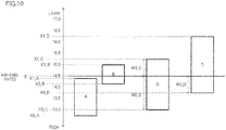
- the straddled vehicle is arranged such that, in the controller, when the secondary air supply control unit controls the secondary air supply valve to be in the open state, the fuel supply amount control unit controls the fuel supplier so that, in a normal state in which the dedicated secondary air supply passage member downstream of the dedicated reed valve does not clog, (i) an air-fuel ratio estimated from a signal of the gas state detection device which is not for the dedicated secondary air supply passage member and detects at least one of oxygen densities of gas in the dedicated exhaust passage member or the upstream exhaust passage member is lean as compared to a stoichiometric air-fuel ratio and (ii) an air-fuel ratio estimated from oxygen density of gas obtained by removing the secondary air supplied to the dedicated exhaust passage member from exhaust gas passing the gas state detection device which is not for the dedicated secondary air supply passage member and detects at least one of oxygen densities of the gas in the dedicated exhaust passage member or the upstream exhaust passage member is rich as compared to an air-fuel ratio in the normal state
- the gas state detection device which is not for the dedicated secondary air supply passage member detects at least one of the oxygen densities of the gas in the dedicated exhaust passage member or the upstream exhaust passage member.
- the fuel supply amount control unit controls the fuel supplier as follows. To begin with, assume that the normal state is set and the dedicated secondary air supply passage member downstream of the dedicated reed valve does not clog.
- An air-fuel ratio estimated from a signal of the gas state detection device which is not for dedicated secondary air supply passage member is referred to as an air-fuel ratio X1.
- a stoichiometric air-fuel ratio is referred to as a stoichiometric air-fuel ratio S.
- the fuel supply amount control unit is configured to control the fuel supplier so that the air-fuel ratio X1 is lean as compared to the stoichiometric air-fuel ratio S.
- the air-fuel ratio X1 estimated from the oxygen density of the exhaust gas flowing into the catalyst is lean as compared to the stoichiometric air-fuel ratio S.
- the air-fuel ratio estimated from the oxygen density of the exhaust gas flowing into the catalyst is lean as compared to the stoichiometric air-fuel ratio S.
- lean indicates a state in which an amount of air is excessive in comparison with the stoichiometric air-fuel ratio and an air-fuel ratio estimated based on the oxygen density of the exhaust gas detected by the oxygen sensor is higher than the stoichiometric air-fuel ratio.
- a stoichiometric air-fuel ratio is referred to as a stoichiometric air-fuel ratio S.
- An air-fuel ratio estimated from the oxygen density of the gas from which the secondary air has been removed is referred to as an air-fuel ratio X0.
- the fuel supply amount control unit is configured to control the fuel supplier so that the air-fuel ratio X0 is rich as compared to the air-fuel ratio X1.
- the air-fuel ratio X0 estimated from the oxygen density of the exhaust gas flowing into the catalyst is rich.
- the stoichiometric air-fuel ratio S is sandwiched between the air-fuel ratio X1 and the air-fuel ratio X0. Therefore, there is a difference W between the air-fuel ratio X1 and the air-fuel ratio X0.
- the difference W is calculated by subtracting the air-fuel ratio X0 from the air-fuel ratio X1. To put it differently, there is a difference between an air-fuel ratio when the secondary air supplied to the dedicated exhaust passage member is not insufficient and an air-fuel ratio when the secondary air is not supplied to the dedicated exhaust passage member.
- the detection unit is configured to detect clogging of the dedicated secondary air supply passage member downstream of the dedicated reed valve based on a signal of the gas state detection device which is not for the dedicated secondary air supply passage member.
- the dedicated secondary air supply passage member downstream of the dedicated reed valve clogs, no secondary air is supplied to the dedicated exhaust passage member.
- the dedicated secondary air supply passage member clogs, the air-fuel ratio estimated from a signal of the gas state detection device which is not for the dedicated secondary air supply passage member becomes rich as compared to the air-fuel ratio X1.
- the air-fuel ratio estimated from a signal of the gas state detection device which is not for dedicated secondary air supply passage member becomes the air-fuel ratio X0.
- the detection unit is therefore able to detect that no secondary air is supplied to the dedicated exhaust passage member downstream of the dedicated reed valve, based on the air-fuel ratio estimated from the signal of the gas state detection device which is not for the dedicated secondary air supply passage member.
- the detection unit is therefore able to certainly detect clogging of the dedicated secondary air supply passage member downstream of the dedicated reed valve based on a signal of the gas state detection device which is not for the dedicated secondary air supply passage member.
- the straddled vehicle is arranged such that, in the controller, when the secondary air supply control unit controls the secondary air supply valve to be in the open state, the fuel supply amount control unit controls the fuel supplier so that, in a normal state in which the dedicated secondary air supply passage member downstream of the dedicated reed valve does not clog, a difference between the air-fuel ratio estimated from the signal of the gas state detection device which is not for the dedicated secondary air supply passage member and detects at least one of oxygen densities of the gas in the dedicated exhaust passage member or the upstream exhaust passage member and the air-fuel ratio estimated from the oxygen density of the gas obtained by removing the secondary air supplied to the dedicated exhaust passage member from the exhaust gas passing the gas state detection device which is not for the dedicated secondary air supply passage member and detects at least one of oxygen densities of the gas in the dedicated exhaust passage member or the upstream exhaust passage member is one or more.
- the gas state detection device which is not for the dedicated secondary air supply passage member detects at least one of the oxygen densities of the gas in the dedicated exhaust passage member or the upstream exhaust passage member.
- the fuel supply amount control unit controls a fuel controller as follows.
- an air-fuel ratio estimated from a signal of the gas state detection device which is not for the dedicated secondary air supply passage member in the normal state in which the dedicated secondary air supply passage member downstream of the dedicated reed valve does not clog is referred to as an air-fuel ratio X1.
- an air-fuel ratio estimated from the oxygen density of gas by removing the secondary air supplied to the dedicated exhaust passage member through the dedicated secondary air supply passage from the exhaust gas passing the gas state detection device which is not for the dedicated secondary air supply passage member, in the normal state in which the dedicated secondary air supply passage member downstream of the dedicated reed valve does not clog is referred to as an air-fuel ratio X0.
- the fuel supply amount control unit is configured to control the fuel supplier so that a difference between the air-fuel ratio X1 and the air-fuel ratio X0 is one or more.
- the air-fuel ratio estimated from the signal of the gas state detection device which is not for the dedicated secondary air supply passage member further varies during a period from the normal state in which the dedicated secondary air supply passage member downstream of the dedicated reed valve does not clog to the occurrence of clogging of the dedicated secondary air supply passage member downstream of the dedicated reed valve.
- the fuel supply amount control unit is therefore able to easily detect clogging of the dedicated secondary air supply passage member downstream of the dedicated reed valve based on a signal of the gas state detection device which is not for the dedicated secondary air supply passage member.
- the straddled vehicle is arranged such that, in the controller, when the secondary air supply control unit controls the secondary air supply valve to be in the open state, the fuel supply amount control unit controls the fuel supplier so that, in a normal state in which the dedicated secondary air supply passage member downstream of the dedicated reed valve does not clog, a difference between the air-fuel ratio estimated from the signal of the gas state detection device detecting at least one of oxygen densities of the gas in the dedicated exhaust passage member or the upstream exhaust passage member and the stoichiometric air-fuel ratio is larger than a difference between the air-fuel ratio estimated from the oxygen density of the gas obtained by removing the secondary air supplied to the dedicated exhaust passage member from the exhaust gas passing the gas state detection device which is not for the dedicated secondary air supply passage member and detects at least one of oxygen densities of the gas in the dedicated exhaust member or the upstream exhaust passage member and the stoichiometric air-fuel ratio.
- the gas state detection device which is not for the dedicated secondary air supply passage member detects at least one of the oxygen densities of the gas in the dedicated exhaust passage member or the upstream exhaust passage member.
- the fuel supply amount control unit controls a fuel controller as follows.
- an air-fuel ratio estimated from a signal of the gas state detection device which is not for the dedicated secondary air supply passage member, in the normal state in which the dedicated secondary air supply passage member downstream of the dedicated reed valve does not clog is referred to as an air-fuel ratio X1.
- an air-fuel ratio estimated from the oxygen density of gas by removing the secondary air supplied to the dedicated exhaust passage member through the dedicated secondary air supply passage from the exhaust gas passing the gas state detection device which is not for the dedicated secondary air supply passage member, in the nonnal state in which the dedicated secondary air supply passage member downstream of the dedicated reed valve does not clog is referred to as an air-fuel ratio X0.
- the fuel supply amount control unit controls the fuel supplier so that the difference between the air-fuel ratio X1 and the stoichiometric air-fuel ratio S is larger than the difference between the air-fuel ratio X0 and the stoichiometric air-fuel ratio S.
- the air-fuel ratio estimated from the signal of the gas state detection device which is not for the dedicated secondary air supply passage member further varies during a period from the nonnal state in which the dedicated secondary air supply passage member downstream of the dedicated reed valve does not clog to the occurrence of clogging of the dedicated secondary air supply passage member downstream of the dedicated reed valve.
- the detection unit is therefore able to easily detect clogging of the dedicated secondary air supply passage member downstream of the dedicated reed valve based on a signal of the gas state detection device which is not for the dedicated secondary air supply passage member.
- the straddled vehicle is arranged such that, in the controller, when the secondary air supply control unit controls the secondary air supply valve to be in the open state, the fuel supply amount control unit controls the fuel supplier so that, in a normal state in which the dedicated secondary air supply passage member downstream of the dedicated reed valve does not clog, a difference between the air-fuel ratio estimated from the oxygen density of the gas obtained by removing the secondary air supplied to the dedicated exhaust passage member from the exhaust gas passing the gas state detection device detecting at least one of oxygen densities of the gas in the dedicated exhaust member or the upstream exhaust passage member and the stoichiometric air-fuel ratio is one or more.
- the gas state detection device which is not for the dedicated secondary air supply passage member detects at least one of the oxygen densities of the gas in the dedicated exhaust passage member or the upstream exhaust passage member.
- the fuel supply amount control unit controls a fuel controller as follows.
- an air-fuel ratio estimated from the oxygen density of gas by removing the secondary air supplied to the dedicated exhaust passage member from the exhaust gas passing the gas state detection device which is not for the dedicated secondary air supply passage member, in the normal state in which the dedicated secondary air supply passage member downstream of the dedicated reed valve does not clog is referred to as an air-fuel ratio X0.
- the fuel supply amount control unit is configured to control the fuel supplier so that the difference between the air-fuel ratio X0 and the stoichiometric air-fuel ratio S is one or more.
- the difference in oxygen density is large between the state in which the secondary air is not supplied and the state in the stoichiometric air-fuel ratio.
- the air-fuel ratio estimated from the signal of the gas state detection device which is not for the dedicated secondary air supply passage member further varies during a period from the normal state in which the dedicated secondary air supply passage member downstream of the dedicated reed valve does not clog to the occurrence of clogging of the dedicated secondary air supply passage member downstream of the dedicated reed valve.
- the detection unit is therefore able to easily detect clogging of the dedicated secondary air supply passage member downstream of the dedicated reed valve based on a signal of the gas state detection device which is not for the dedicated secondary air supply passage member.
- the straddled vehicle is arranged such that, in the controller, when the secondary air supply control unit controls the secondary air supply valve to be in the open state, the detection unit is able to detect fixation of the dedicated reed valve to the closed state based on a signal of the gas state detection device which is not for the dedicated secondary air supply passage member.
- the detection unit when the secondary air supply control unit controls the secondary air supply valve to be in the open state, the detection unit is able to detect fixation of the dedicated reed valve to the closed state.
- the dedicated reed valve When the dedicated reed valve is fixed to the closed state, no secondary air is supplied to the dedicated exhaust passage member from the dedicated secondary air supply passage member downstream of the dedicated reed valve. In other words, the secondary air supplied to the dedicated exhaust passage member becomes insufficient as compared to the normal state in which the dedicated reed valve is not fixed to the closed state.
- the detection unit of the controller is therefore able to detect the fixation of the dedicated reed valve to the closed state by using a signal of the gas state detection device which is not for the dedicated secondary air supply passage member and is configured to detect an index indicating the state of the gas in the passage members other than the dedicated secondary air supply passage member downstream of the dedicated reed valve.
- the detected information can be recorded on the controller. Based on the recorded information, it is possible to prompt a rider, etc.
- the straddled vehicle is arranged such that, in the controller, when the secondary air supply control unit controls the secondary air supply valve to be in the open state, the detection unit is able to detect fixation of the secondary air supply valve to the closed state based on a signal of the gas state detection device which is not for the dedicated secondary air supply passage member.
- the detection unit when the secondary air supply control unit controls the secondary air supply valve to be in the open state, the detection unit is able to detect fixation of the secondary air supply valve to the closed state.
- the secondary air supply valve is fixed to the closed state, even if the secondary air supply control unit controls the secondary air supply valve to be in the open state, the secondary air is not supplied to the dedicated secondary air supply passage member downstream of the secondary air supply valve in the flow direction of the secondary air. In other words, no secondary air is supplied to the dedicated exhaust passage member.
- the secondary air includes oxygen and is colder than the exhaust gas.
- the dedicated exhaust passage member communicates with the dedicated secondary air supply passage member, backward flow of the exhaust gas in the dedicated exhaust passage member to the dedicated secondary air supply passage member occurs on account of exhaust pulse in the dedicated exhaust passage member.
- the air-fuel ratio estimated based on the oxygen densities of the gas in the dedicated exhaust passage member and the upstream exhaust passage member becomes a value on the rich side.
- the temperatures of the gas in the dedicated exhaust passage member, the upstream exhaust passage member, the catalyst exhaust passage member, and the downstream exhaust passage member become low.
- the temperature of the downstream secondary air supply passage member becomes high.
- the flow rates of the gas in the downstream secondary air supply passage member and the upstream secondary air supply passage member are eliminated.
- the pressure of the gas in the upstream secondary air supply passage member becomes high.
- the pressure of the gas in the downstream secondary air supply passage member may become high.
- the oxygen density, the temperature, the flow rate, and the pressure of the gas are indexes indicating the state of the gas in the passage members other than the dedicated secondary air supply passage member downstream of the dedicated reed valve.
- the detection unit is therefore able to detect the fixation of the secondary air supply valve to the closed state by using a signal of the gas state detection device which is not for the dedicated secondary air supply passage member and is configured to detect indexes indicating the state of the gas, including at least one of the indexes above.
- the detected information can be recorded on the controller.
- the straddled vehicle is arranged such that, in the controller, when the secondary air supply control unit controls the secondary air supply valve to be in the closed state, the detection unit is able to detect fixation of the secondary air supply valve to the open state based on a signal of the gas state detection device which is not for the dedicated secondary air supply passage member.
- the detection unit when the secondary air supply control unit controls the secondary air supply valve to be in the closed state, the detection unit is able to detect fixation of the secondary air supply valve to the open state.
- the secondary air supply valve is fixed to the open state, even if the secondary air supply control unit controls the secondary air supply valve to be in the closed state, the secondary air is supplied to the dedicated exhaust passage member.
- the secondary air supply valve is fixed to the open state, the following changes occur as compared to the normal state in which the secondary air supply valve is not fixed to the open state.
- a correction amount of the fuel supply amount which is calculated based on the oxygen densities of the gas in the dedicated exhaust passage member and the upstream exhaust passage member, continues to vary without converging.
- the temperatures of the gas in the downstream secondary air supply passage member and the upstream secondary air supply passage member become low.
- the pressures of the gas in the downstream secondary air supply passage member and the upstream secondary air supply passage member change to negative pressures and become low.
- a negative pressure indicates a pressure lower than the atmospheric pressure.
- the flow rates of the gas in the downstream secondary air supply passage member and the upstream secondary air supply passage become high.
- the oxygen density, the temperature, the pressure, and the flow rate of the gas are indexes indicating the state of the gas in the passage members other than the dedicated secondary air supply passage member downstream of the dedicated reed valve.
- the detection unit is therefore able to detect the fixation of the secondary air supply valve to the open state by using a signal of the gas state detection device which is not for the dedicated secondary air supply passage member and is configured to detect indexes indicating the state of the gas, including at least one of the indexes above.
- the detected information can be recorded on the controller. Based on the recorded information, it is possible to prompt a rider, etc. to perform maintenance of the dedicated secondary air supply passage. As a result of maintenance of the dedicated secondary air supply passage, the fixation of the secondary air supply valve to the open state is resolved. In this way, the engine performance of the engine unit including the dedicated reed valve and the dedicated secondary air supply passage member downstream of the dedicated reed valve and the purification performance of purifying the exhaust gas are both achieved.
- the straddled vehicle is arranged such that, in the controller, when the secondary air supply control unit controls the secondary air supply valve to be in the closed state, the detection unit is able to detect fixation of the dedicated reed valve to the open state based on a signal of the gas state detection device which is not for the dedicated secondary air supply passage member.
- the detection unit when the secondary air supply control unit controls the secondary air supply valve to be in the closed state, the detection unit is able to detect fixation of the dedicated reed valve to the open state.
- the dedicated reed valve if the dedicated reed valve is fixed to the open state, backward flow of exhaust gas from the dedicated exhaust passage member to the dedicated secondary air supply passage member occurs, even if the secondary air supply valve is controlled to be in the closed state.
- the dedicated reed valve when the dedicated reed valve is fixed to the open state, the following changes occur as compared to the normal state in which the dedicated reed valve is not fixed to the open state. The temperatures of the gas in the downstream secondary air supply passage member and the upstream secondary air supply passage member become high.
- the pressure in the downstream secondary air supply passage member varies not only to a negative pressure but also to a positive pressure and becomes high.
- a positive pressure indicates a pressure higher than the atmospheric pressure.
- the detection unit is therefore able to detect the fixation of the dedicated reed valve to the open state by using a signal of the gas state detection device which is not for the dedicated secondary air supply passage member and is configured to detect an index indicating the state of the gas in the passage members other than the dedicated secondary air supply passage member downstream of the dedicated reed valve.
- the detected information can be recorded on the controller. Based on the recorded information, it is possible to prompt a rider, etc. to perform maintenance of the dedicated secondary air supply passage.
- the fixation of the dedicated reed valve to the open state is resolved.
- the engine performance of the engine unit including the dedicated reed valve and the dedicated secondary air supply passage member downstream of the dedicated reed valve and the purification performance of purifying the exhaust gas are both achieved.
- the straddled vehicle is arranged such that, in the controller, when the secondary air supply control unit controls the secondary air supply valve to be in the open state, the detection unit is able to detect that the dedicated secondary air supply passage member downstream of the dedicated reed valve is about to clog based on a signal of the gas state detection device which is not for the dedicated secondary air supply passage member.
- the controller detects that the dedicated secondary air supply passage member downstream of the dedicated reed valve is about to clog.
- the dedicated secondary air supply passage member downstream of the dedicated reed valve is about to clog
- the effective flow area of the dedicated secondary air supply passage member downstream of the dedicated reed valve has been narrowed.
- the expression "the effective flow area has been narrowed" does not encompass a case where the effective flow area is zero.
- the flow rate of the secondary air supplied to the dedicated exhaust passage member through the dedicated secondary air supply passage member becomes smaller than a predetermined flow rate.
- the predetermined flow rate is stored in advance in the controller, based on a required flow rate.
- the required flow rate is a flow rate of secondary air supplied to the dedicated exhaust passage member in the normal state in which the dedicated secondary air supply passage member downstream of the dedicated reed valve is not about to clog.
- the detection unit is therefore able to detect that the dedicated secondary air supply passage member downstream of the dedicated reed valve is about to clog by using a signal of the gas state detection device which is not for the dedicated secondary air supply passage member and is configured to detect an index indicating the state of the gas in the passage members other than the dedicated secondary air supply passage member downstream of the dedicated reed valve.
- the detected information can be recorded on the controller. Based on the recorded information, it is possible to prompt a rider, etc. to perform maintenance of the dedicated secondary air supply passage. As a result of maintenance inside the dedicated secondary air supply passage, the problem that the dedicated secondary air supply passage member downstream of the dedicated reed valve is about to clog is resolved.
- the engine main body includes a plurality of the combustion chambers.
- the engine main body includes a plurality of combustion chambers.
- the engine main body is a multi-cylinder engine.
- the detection unit of the controller is able to detect that the dedicated secondary air supply passage member downstream of one or plural dedicated reed valve clogs or is about to clog, that one or plural dedicated reed valve is fixed to the closed state or the open state, and that one or plural on-off valve is fixed to the closed state or the open state.
- the engine main body includes one combustion chamber.
- the engine main body includes one combustion chamber.
- the engine main body is a single-cylinder engine.
- the detection unit of the controller is able to detect that the dedicated secondary air supply passage member downstream of one dedicated reed valve clogs or is about to clog, that one dedicated reed valve is fixed to the closed state or the open state, and that one on-off valve is fixed to the closed state or the open state.
- the straddled vehicle further includes a notification unit, the controller further including a notification command unit which is configured to send, to the notification unit, at least a signal notifying clogging of the dedicated secondary air supply passage member downstream of the dedicated reed valve, when the detection unit detects the clogging of the dedicated secondary air supply passage member downstream of the dedicated reed valve.
- the straddled vehicle further includes the notification unit.
- the controller further includes the notification command unit.
- the notification command unit sends, to the notification unit, a signal notifying the clogging of the dedicated secondary air supply passage member downstream of the dedicated reed valve.
- the notification command unit sends the notification signal when the detection unit detects at least the clogging of the dedicated secondary air supply passage member downstream of the dedicated reed valve. This allows the rider or a maintenance personnel to recognize the clogging of the dedicated secondary air supply passage member downstream of the dedicated reed valve.
- the notification command unit may send a notification signal when fixation of the dedicated reed valve to the closed state is detected.
- the notification command unit may send a notification signal when fixation of the secondary air supply valve to the closed state is detected.
- the notification command unit may send a notification signal when fixation of the dedicated reed valve to the open state is detected.
- the notification command unit may send a notification signal when fixation of the secondary air supply valve to the open state is detected.
- the notification command unit may send a notification signal when it is detected that the dedicated secondary air supply passage member downstream of the dedicated reed valve is about to clog.
- the straddled vehicle is arranged such that, a timing at which the detection unit determines whether the dedicated secondary air supply passage member downstream of the dedicated reed valve clogs based on a signal of the gas state detection device which is not for the dedicated secondary air supply passage member is a timing at which the secondary air supply control unit controls the secondary air supply valve to be in the open state and the fuel supply amount control unit causes the engine main body to be driven in a predetermined driving range.
- the timing at which the detection unit determines whether the dedicated secondary air supply passage member downstream of the dedicated reed valve clogs based on a signal of the gas state detection device which is not for the dedicated secondary air supply passage member is as follows.
- the timing is a timing at which the secondary air supply control unit controls the secondary air supply valve to be in the open state and the fuel supply amount control unit causes the engine main body to be driven in a predetermined driving range.
- the controller causes the secondary air supply control unit to control the secondary air supply valve to be in the open state, so as to supply secondary air to the dedicated exhaust passage member.
- the secondary air supply control unit typically controls the secondary air supply valve to be in the open state when the fuel supply amount control unit causes the engine main body to be driven at least under the cold state and in the predetermined driving range.
- the detection unit is able to detect the clogging of the dedicated secondary air supply passage member downstream of the dedicated reed valve by using a signal of the gas state detection device which is not for the dedicated secondary air supply passage member, when the secondary air supply control unit typically supplies secondary air to the dedicated exhaust passage member.
- the straddled vehicle is arranged such that a timing at which the detection unit determines whether the dedicated secondary air supply passage member downstream of the dedicated reed valve clogs based on a signal of the gas state detection device which is not for the dedicated secondary air supply passage member is a timing at which the fuel supply amount control unit controls the engine main body to be driven in the warm-up state and in a predetermined driving range different from the driving range which is at least a part of the low-load range, and the secondary air supply control unit controls the secondary air supply valve to be in the open state.
- the timing at which the detection unit determines whether the dedicated secondary air supply passage member downstream of the dedicated reed valve clogs based on a signal of the gas state detection device which is not for the dedicated secondary air supply passage member is as follows.
- This timing is a timing at which the fuel supply amount control unit controls the engine main body to be driven in the warm-up state and in a predetermined driving range different from the driving range which is at least a part of the low-load range, and the secondary air supply control unit controls the secondary air supply valve to be in the open state.
- the secondary air supply control unit typically controls the secondary air supply valve to be in the closed state so as not to supply secondary air to the dedicated exhaust passage member.
- the secondary air supply control unit controls the secondary air supply valve to be in the open state to supply the secondary air to the dedicated exhaust passage member. Then the detection unit detects the clogging of the dedicated secondary air supply passage member downstream of the dedicated reed valve. In other words, even when the secondary air supply control unit typically does not supply secondary air to the dedicated exhaust passage member, the detection unit of the controller is able to detect the clogging of the dedicated secondary air supply passage member downstream of the dedicated reed valve by supplying the secondary air to the dedicated exhaust passage member. In this way, it is possible to improve both the engine performance of the engine unit including the dedicated reed valve and the dedicated secondary air supply passage member downstream of the dedicated reed valve and the purification performance of purifying the exhaust gas.
- the effective flow area of the dedicated secondary air supply passage member downstream of the dedicated reed valve is zero.
- the dedicated secondary air supply passage member downstream of the dedicated reed valve is about to clog, the effective flow area of the dedicated secondary air supply passage member downstream of the dedicated reed valve has been narrowed.
- the expression "the effective flow area has been narrowed" does not encompass a case where the effective flow area is zero.
- the required flow rate is a flow rate of secondary air supplied to the dedicated exhaust passage member in the normal state in which the dedicated secondary air supply passage member downstream of the dedicated reed valve is not about to clog.
- the normal state is a state in which the secondary air supply valve and the dedicated reed valve operate normally and the dedicated secondary air supply passage member downstream of the dedicated reed valve does not clog or is not about to clog.
- the normal state is a state in which the dedicated secondary air supply passage member downstream of the dedicated reed valve does not clog.
- the normal state is a state in which the dedicated reed valve is not fixed to the closed state.
- the normal state is a state in which the secondary air supply valve is not fixed to the closed state.
- the normal state is a state in which the dedicated reed valve is not fixed to the open state.
- the normal state is a state in which the secondary air supply valve is not fixed to the open state.
- the normal state is a state in which the dedicated secondary air supply passage member downstream of the dedicated reed valve is not about to clog.
- a passage indicates a space in which gas passes.
- a passage member is a structure forming a path.
- the full-open state indicates a state in which an opening degree is 100.
- the full-closed state indicates a state in which an opening degree is 0.
- the partially-open state indicates a state in which an opening degree is larger than 0 and smaller than 100.
- the open state indicates a state in which a valve is open.
- the open state encompasses the full-open state and a partially-open state.
- the closed state indicates a state in which a valve is closed. In this specification, the closed state is limited to the full-closed state.
- control of the secondary air supply valve to be in the open state indicates that a signal instructing the secondary air supply valve to open has been sent from the secondary air supply control unit to the secondary air supply valve. It does not matter whether the secondary air supply valve has properly opened or not.
- control of the secondary air supply valve to be in the closed state indicates that a signal instructing the secondary air supply valve to be closed has been sent from the secondary air supply control unit to the secondary air supply valve. It does not matter whether the secondary air supply valve has properly been closed or not.
- an air-fuel ratio indicates the ratio of an air mass to a fuel mass in an air-fuel mixture in a combustion chamber.
- the stoichiometric air-fuel ratio indicates an air-fuel ratio at which oxygen and fuel in air-fuel mixture fully react with each other.
- the control of the fuel supply amount includes control of an amount of fuel supplied from the fuel pump and control of time of injecting fuel by the injector (fuel supplier).
- the dedicated reed valve includes a reed valve body and a housing (passage member) in which the reed valve body is provided.
- the secondary air supply valve includes a valve body and a housing (passage member) in which the valve body is provided.
- the detection timing is a timing at which the detection unit determines whether the dedicated secondary air supply passage member downstream of the dedicated reed valve clogs or not.
- the detection timing is not only an exact time point but also a predetermined duration from a time point.
- a signal detected by a sensor is an average value. This is applicable to the detection timing at which the detection unit detects fixation of the dedicated reed valve to the closed state. This is applicable to the detection timing at which the detection unit detects fixation of the secondary air supply valve to the closed state. This is applicable to the detection timing at which the detection unit detects that the dedicated secondary air supply passage member downstream of the dedicated reed valve is about to clog. This is applicable to the detection timing at which the detection unit detects an abnormality in the secondary air supply valve in the open state. The same applies to the detection timing at which the detection unit detects an abnormality in the dedicated reed valve in the open state.
- a predetermined driving range is, for example, a predetermined load range and a predetermined rotation range which are set in advance.
- the predetermined load range indicates that a load falls within a predetermined range of loads.
- the predetermined rotation range indicates that an engine rotation speed falls within a predetermined range of rotation speeds.
- control of the fuel supply amount includes control of an amount of fuel supplied from the fuel pump and control of time of injecting fuel by the injector.
- an end portion of a member indicates a portion constituted by an end and its surroundings of the member.
- an expression “members A and B are provided side by side in an X direction” indicates the following state. When the members A and B are viewed in a direction orthogonal to the X direction, the members A and B are both provided on a linear line which is parallel to the X direction. In the present teaching, an expression “members A and B are provided side by side in an X direction when viewed in a Y direction” indicates the following state. When the members A and B are viewed in the Y direction, the members A and B are both provided on a linear line which is parallel to the X direction.
- the members A and B when the members A and B are viewed in a W direction which is different from the Y direction, at least one of the members A or B may not be provided on the linear line which is parallel to the X direction.
- the members A and B may be in contact with each other.
- the members A and B may not be in contact with each other.
- a member C may be provided between the members A and B.
- an expression "a member A is provided forward of a member B" indicates the following state.
- the member A is provided in front of a plane which passes the front-most end of the member B and is orthogonal to the front-rear direction.
- the members A and B may or may not be lined up in the front-rear direction. This applies to the directions other than the front-rear direction. (That is to say, this applies to the directions other than "forward of”, such as "rearward of", "leftward of", and "rightward of”.)
- an expression "a member A is provided in front of a member B" indicates the following state.
- the members A and B are lined up in the front-rear direction and a part of the member A, the part facing the member B, is provided in front of the member B.
- the member A when a part of the front surface of the member B, the part facing the member A, is the front-most end of the member B, the member A is provided forward of the member B.
- the member A when a part of the front surface of the member B, the part facing the member A, is not the front-most end of the member B, the member A may or may not be provided forward of the member B. This applies to the directions other than the front-rear direction.
- the front surface of the member B is a surface which is viewable when the member B is viewed from the front side.
- the front surface of the member B may be formed of plural surfaces, instead of a single continuous surface.
- an expression "a member A is provided in front of a member B when viewed in the left-right direction” indicates the following state.
- the members A and B are lined up in the front-rear direction when viewed in the left-right direction and a part of the member A, the part facing the member B, is provided in front of the member B when viewed in the left-right direction.
- the members A and B may not be lined up in the front-rear direction in three dimensions. This applies to the directions other than the front-rear direction. (That is to say, this applies to the directions other than "in front of", such as "behind”, "to the left of", and "to the right of".)
- the use of the terms “including”, “comprising”, “having” and their derivatives specify the existence of a feature, a step, an operation, an element, a component, and/or their equivalents, which are described in this specification, but may encompass one or more of a step, an action, an element, a component, and/or a group of each of them.
- the terms “attached”, “connected”, “coupled”, and/or their equivalents are broadly used and encompass both direct and indirect attachment, connection, and coupling.
- the terms “connected” and “coupled” are not limited to physical or mechanical connection and coupling, and indicate direct or indirect electrical connection or coupling.
- an engine performance and a purification performance of purifying an exhaust gas are both achieved in an engine unit including a dedicated reed valve and a dedicated secondary air supply passage member downstream of the dedicated reed valve.
- the straddled vehicle 1 includes a vehicle body frame 4, a seat 9, and an engine unit 11.
- the seat 9 is supported by the vehicle body frame 4.
- the engine unit 11 is provided below the upper end of the seat 9.
- the engine unit 11 is supported by the vehicle body frame 4.
- the engine unit 11 includes at least one combustion chamber 30, a fuel supplier 55 provided for each combustion chamber 30, and a catalyst 65 provided for each combustion chamber 30.
- the at least one combustion chamber 30 is formed inside an engine main body 20.
- the fuel supplier 55 is configured to supply fuel to the combustion chamber 30.
- the catalyst 65 is configured to purify exhaust gas passing a dedicated exhaust passage 69.
- the dedicated exhaust passage 69 is a passage from the combustion chamber 30 to a discharge port 64a. Exhaust gas is discharged to the atmosphere via the discharge port 64a.
- the engine unit 11 includes a dedicated reed valve 84 which is provided for each combustion chamber 30.
- the dedicated reed valve 84 is provided on a dedicated secondary air supply passage 85.
- the dedicated secondary air supply passage 85 supplies, as secondary air, air sucked through an air inlet 51a to the dedicated exhaust passage 69. Air is sucked from the atmosphere through the air inlet 51a.
- the dedicated reed valve 84 is in an open state when a pressure difference by subtracting the pressure in the dedicated secondary air supply passage 85 which is downstream of the dedicated reed valve 84 in the flow direction of the secondary air from the pressure in the dedicated secondary air supply passage 85 which is upstream of the dedicated reed valve 84 in the flow direction of the secondary air is equal to or larger than a predetermined pressure.
- the dedicated reed valve 84 opens the dedicated secondary air supply passage 85.
- the dedicated reed valve 84 is in a closed state when a pressure difference by subtracting the pressure in the dedicated secondary air supply passage 85 which is downstream of the dedicated reed valve 84 in the flow direction of the secondary air from the pressure in the dedicated secondary air supply passage 85 which is upstream of the dedicated reed valve 84 in the flow direction of the secondary air is smaller than the predetermined pressure.
- the dedicated reed valve 84 closes the dedicated secondary air supply passage 85.
- the engine unit 11 includes a secondary air supply valve 83.
- the secondary air supply valve 83 is provided upstream, in the flow direction of the secondary air, of the dedicated reed valve 84 on the dedicated secondary air supply passage 85.
- the secondary air supply valve 83 opens the dedicated secondary air supply passage 85 so as to allow supply of the secondary air to the dedicated secondary air supply passage 85.
- the secondary air supply valve 83 closes the dedicated secondary air supply passage 85 so as to stop supply of the secondary air to the dedicated secondary air supply passage 85.
- the engine unit 11 includes a dedicated exhaust passage member 66 which is provided for each combustion chamber 30.
- the dedicated exhaust passage member 66 is connected to the combustion chamber 30 at an upstream end portion of the dedicated exhaust passage member 66 in the flow direction of the exhaust gas.
- a part of the dedicated exhaust passage 69 is formed inside the dedicated exhaust passage member 66.
- the engine unit 11 includes an upstream exhaust passage member 67.
- the upstream exhaust passage member 67 is connected to the dedicated exhaust passage member 66 at an upstream end portion of the upstream exhaust passage member 67 in the flow direction of the exhaust gas.
- the upstream exhaust passage member 67 is provided upstream of the catalyst 65 in the flow direction of the exhaust gas.
- a part of the dedicated exhaust passage 69 is formed inside the upstream exhaust passage member 67.
- the engine unit 11 includes a catalyst exhaust passage member 68.
- the catalyst exhaust passage member 68 is connected to the upstream exhaust passage member 67 at an upstream end portion of the catalyst exhaust passage member 68 in the flow direction of the exhaust gas.
- the catalyst exhaust passage member 68 includes the catalyst 65.
- a part of the dedicated exhaust passage 69 is formed inside the catalyst 65.
- the engine unit 11 includes a downstream exhaust passage member 64.
- the downstream exhaust passage member 64 is connected to the catalyst exhaust passage member 68 at an upstream end portion of the downstream exhaust passage member 64 in the flow direction of the exhaust gas.
- the downstream exhaust passage member 64 includes the discharge port 64a at a downstream end portion in the flow direction of the exhaust gas.
- the downstream exhaust passage member 64 is provided downstream of the catalyst 65 in the flow direction of the exhaust gas.
- the engine unit 11 includes a dedicated secondary air supply passage member 87 which is downstream of the dedicated reed valve.
- the dedicated secondary air supply passage member 87 is provided for each combustion chamber 30.
- the dedicated secondary air supply passage member 87 downstream of the dedicated reed valve is connected to the dedicated exhaust passage member 66 at a downstream end portion of the dedicated secondary air supply passage member 87 in the flow direction of the secondary air.
- the dedicated secondary air supply passage member 87 downstream of the dedicated reed valve is connected to the dedicated reed valve 84 at an upstream end portion of the dedicated secondary air supply passage member 87 in the flow direction of the secondary air.
- a part of the dedicated secondary air supply passage 85 is formed inside the dedicated secondary air supply passage member 87 downstream of the dedicated reed valve.
- the dedicated secondary air supply passage member 87 downstream of the dedicated reed valve is provided downstream of the dedicated reed valve 84 in the flow direction of the secondary air.
- the engine unit 11 includes a downstream secondary air supply passage member 88b.
- the downstream secondary air supply passage member 88b is connected to the dedicated reed valve 84 at a downstream end portion of the downstream secondary air supply passage member 88b in the flow direction of the secondary air.
- the downstream secondary air supply passage member 88b is connected to the secondary air supply valve 83 at an upstream end portion of the downstream secondary air supply passage member 88b in the flow direction of the secondary air.
- a part of the dedicated secondary air supply passage 85 is formed inside the downstream secondary air supply passage member 88b.
- the downstream secondary air supply passage member 88b is provided downstream of the secondary air supply valve 83.
- the engine unit 11 includes an upstream secondary air supply passage member 88a.
- the upstream secondary air supply passage member 88a is connected to the secondary air supply valve 83 at a downstream end portion of the upstream secondary air supply passage member 88a in the flow direction of the secondary air.
- the upstream secondary air supply passage member 88a includes the air inlet 51a at an upstream end portion in the flow direction of the secondary air.
- a part of the dedicated secondary air supply passage 85 is formed inside the upstream secondary air supply passage member 88a.
- the upstream secondary air supply passage member 88a is provided upstream of the secondary air supply valve 83.
- the engine unit 11 includes a gas state detection device 70 which is not for the dedicated secondary air supply passage member.
- the gas state detection device 70 which is not for the dedicated secondary air supply passage member will be simply referred to as a gas state detection device 70.
- the gas state detection device 70 is configured to detect an index indicating the state of gas in passage members, except the dedicated secondary air supply passage member 87 downstream of the dedicated reed valve.
- the detection of the index indicating the state of the gas in the passage members other than the dedicated secondary air supply passage member 87 downstream of the dedicated reed valve indicates at least one of the following (1) to (4).
- the index indicating the state of gas to be detected indicates at least one of the oxygen density, the temperature, the pressure, or the flow rate of the gas in the above-described passage members.
- the engine unit 11 includes a controller 90.
- the controller 90 includes a fuel supply amount control unit 92, a secondary air supply control unit 91, and a detection unit 96.
- the fuel supply amount control unit 92 is configured to control an amount of fuel supplied by the fuel supplier 55.
- the secondary air supply control unit 91 is configured to control the secondary air supply valve 83 to be in an open state or a closed state.
- the secondary air supply control unit 91 is configured to control the secondary air supply valve 83 to be in the open state when the engine main body 20 drives at least under a cold state.
- the detection unit 96 is configured to be able to detect clogging of the dedicated secondary air supply passage member 87 downstream of the dedicated reed valve based on a signal from the gas state detection device 70, when the secondary air supply control unit 91 controls the secondary air supply valve 83 to be in the open state.
- the straddled vehicle 1 of the embodiment of the present teaching has the following characteristics.
- the dedicated reed valve 84 is provided for each combustion chamber 30.
- the dedicated reed valve 84 is connected to the downstream secondary air supply passage member 88b and the dedicated secondary air supply passage member 87 downstream of the dedicated reed valve.
- the secondary air supply valve 83 is connected to the upstream end portion of the downstream secondary air supply passage member 88b in the flow direction of the secondary air and the downstream end portion of the upstream secondary air supply passage member 88a in the flow direction of the secondary air.
- the fuel supply amount control unit 92 of the controller 90 is configured to control the secondary air supply valve 83 to be in the open state when the engine main body 20 is driven at least under the cold state.
- the secondary air supply valve 83 In the open state, the secondary air supply valve 83 causes the downstream secondary air supply passage member 88b to communicate with the upstream secondary air supply passage member 88a. In the closed state, the secondary air supply valve 83 disconnects the downstream secondary air supply passage member 88b from the upstream secondary air supply passage member 88a.
- the control of the secondary air supply valve 83 to be in the open state indicates that a signal instructing the secondary air supply valve 83 to open has been sent from the controller 90 to the secondary air supply valve 83. It does not matter whether the secondary air supply valve 83 has properly opened or not.
- the dedicated reed valve 84 is in the open state in the following case.
- a pressure difference by subtracting the pressure in the dedicated secondary air supply passage 85 in the dedicated secondary air supply passage member 87 downstream of the dedicated reed valve from the pressure in the dedicated secondary air supply passage 85 in the downstream secondary air supply passage member 88b is equal to or higher than a predetermined pressure.
- the dedicated reed valve 84 causes the downstream secondary air supply passage member 88b to communicate with the dedicated secondary air supply passage member 87 downstream of the dedicated reed valve.
- the dedicated reed valve 84 is in the closed state in the following case.
- the pressure difference by subtracting the pressure in the dedicated secondary air supply passage 85 in the dedicated secondary air supply passage member 87 downstream of the dedicated reed valve from the pressure in the dedicated secondary air supply passage 85 in the downstream secondary air supply passage member 88b is lower than the predetermined pressure.
- the dedicated reed valve 84 disconnects the downstream secondary air supply passage member 88b from the dedicated secondary air supply passage member 87 downstream of the dedicated reed valve.
- the dedicated reed valve 84 is opened or closed based on the pressure difference between the pressure in the dedicated secondary air supply passage 85 in the downstream secondary air supply passage member 88b and the pressure in the dedicated secondary air supply passage 85 in the dedicated secondary air supply passage member 87 downstream of the dedicated reed valve.
- the exhaust gas is periodically exhausted from the combustion chamber 30 to the dedicated exhaust passage member 66.
- the pressure in the dedicated exhaust passage member 66 periodically varies on account of the exhaust gas.
- the pressure in the dedicated secondary air supply passage member 87 downstream of the dedicated reed valve and connected to the dedicated exhaust passage member 66 periodically varies.
- the pressure in the downstream secondary air supply passage member 88b downstream of the dedicated reed valve and connected to the upstream end portion the dedicated secondary air supply passage member 87 in the flow direction of the secondary air is equal to the atmospheric pressure.
- the dedicated reed valve 84 is opened and closed when the secondary air supply valve 83 is in the open state.
- the secondary air is supplied to the dedicated exhaust passage member 66 via the dedicated secondary air supply passage member 87 downstream of the dedicated reed valve. Unburned substances in the exhaust gas are burned by using the secondary air supplied to the dedicated exhaust passage member 66. Furthermore, oxygen deficiency in the catalyst 65 is resolved. Because the oxygen density in the exhaust gas supplied to the catalyst 65 increases, the oxidation of the catalyst 65 is facilitated. It is therefore possible to further increase the temperature of the catalyst 65.
- the secondary air is not supplied to the dedicated exhaust passage member 66 when the dedicated reed valve 84 is in the closed state or when the secondary air supply valve 83 is in the closed state.
- the gas state detection device 70 is configured to detect an index indicating the state of gas in passage members, except the dedicated secondary air supply passage member 87 downstream of the dedicated reed valve.
- the gas in the passage members except the dedicated secondary air supply passage member 87 downstream of the dedicated reed valve is gas in at least one of the dedicated exhaust passage member 66, the upstream exhaust passage member 67, the catalyst exhaust passage member 68, the downstream exhaust passage member 64, the downstream secondary air supply passage member 88b, or the upstream secondary air supply passage member 88a.
- the index indicating the state of gas to be detected indicates at least one of the oxygen density of the gas, the temperature of the gas, the pressure of the gas, or the flow rate of the gas.
- the fuel supply amount control unit 92 of the controller 90 is configured to control the fuel supplier 55 in accordance with a required engine performance.
- the detection unit 96 of the controller 90 is configured to be able to detect clogging of the dedicated secondary air supply passage member downstream of the dedicated reed valve based on a signal from the gas state detection device 70, when the secondary air supply control unit 91 controls the secondary air supply valve 83 to be in the open state.
- the dedicated secondary air supply passage member 87 downstream of the dedicated reed valve clogs, secondary air is not supplied from the dedicated secondary air supply passage member 87 downstream of the dedicated reed valve to the dedicated exhaust passage member 66. In other words, the secondary air supplied to the dedicated exhaust passage member 66 becomes insufficient.
- the secondary air includes oxygen and is colder than the exhaust gas.
- the dedicated secondary air supply passage member 87 downstream of the dedicated reed valve is disconnected from the downstream secondary air supply passage member 88b. For this reason, backward flow of the exhaust gas in the dedicated exhaust passage member 66 to the downstream secondary air supply passage member 88b via the dedicated secondary air supply passage member 87 downstream of the dedicated reed valve does not occur on account of exhaust pulse in the dedicated exhaust passage member 66.
- the dedicated secondary air supply passage member 87 downstream of the dedicated reed valve clogs, the following changes occur as compared to a normal state in which the dedicated secondary air supply passage member 87 downstream of the dedicated reed valve does not clog.
- the air-fuel ratio estimated based on the oxygen densities of the exhaust gas in the dedicated exhaust passage member 66 and the upstream exhaust passage member 67 becomes a value on the rich side.
- the term "rich” indicates a state in which an amount of fuel is excessive in comparison with the stoichiometric air-fuel ratio and an air-fuel ratio estimated based on the oxygen density of the exhaust gas is lower than the stoichiometric air-fuel ratio.
- the stoichiometric air-fuel ratio indicates an air-fuel ratio at which oxygen and fuel in air-fuel mixture fully react with each other.
- the temperatures of the gas in the downstream secondary air supply passage member 88b, the upstream secondary air supply passage member 88a, the dedicated exhaust passage member 66, the upstream exhaust passage member 67, the catalyst exhaust passage member 68, and the downstream exhaust passage member 64 are lowered. Ranges of variations of the pressures of the gas in the downstream secondary air supply passage member 88b and the upstream secondary air supply passage member 88a are eliminated or decreased. The flow rates of the gas in the downstream secondary air supply passage member 88b or the upstream secondary air supply passage member 88a are eliminated or decreased. They are indexes indicating the state of the gas in the passage members other than the dedicated secondary air supply passage member 87 downstream of the dedicated reed valve.
- the gas state detection device 70 is configured to detect an index which indicates the state of gas including at least one of these oxygen density, temperature, pressure, or flow rate and which indicates the state of gas in the passage members other than the dedicated secondary air supply passage member 87 downstream of the dedicated reed valve.
- the detection unit 96 of the controller 90 is therefore able to detect clogging of the dedicated secondary air supply passage member 87 downstream of the dedicated reed valve, by using a signal of the gas state detection device 70.
- the detected information may be recorded on the controller 90. Based on the recorded information, it is possible to prompt a rider, etc. to perform maintenance of the dedicated secondary air supply passage 85.
- the dedicated secondary air supply passage 85 As a result of maintenance inside the dedicated secondary air supply passage 85, the clogging of the dedicated secondary air supply passage member 87 downstream of the dedicated reed valve is resolved. Consequently, the insufficiency of the secondary air supplied to the dedicated exhaust passage member 66 is resolved. The purification performance of purifying the exhaust gas is therefore recovered. In this way, the engine performance of the engine unit 11 including the dedicated reed valve 84 and the dedicated secondary air supply passage member 87 downstream of the dedicated reed valve and the purification performance of purifying the exhaust gas are both achieved.
- a vehicle front-rear direction, a vehicle left-right direction, and a vehicle up-down direction indicate a front-rear direction, a left-right direction, and an up-down direction for a rider seated on a later-described seat 9 of the motorcycle 1, respectively.
- the motorcycle is provided on a horizontal plane.
- the signs F, B, L, R, U, and D in the figures indicate forward, rearward, leftward, rightward, upward, and downward, respectively.
- the motorcycle 1 includes a front wheel 2, a rear wheel 3, and a vehicle body frame 4. On the whole, the vehicle body frame 4 extends in the front-rear direction.
- the vehicle body frame 4 includes a head pipe 4a at a front portion.
- a steering shaft (not illustrated) is rotatably inserted into the head pipe 4a.
- An upper end portion of the steering shaft is connected to a handle unit 5.
- Upper end portions of paired front forks 6 are secured to the handle unit 5.
- a lower end portion of each front fork 6 supports the front wheel 2.
- the handle unit 5 includes a single handlebar 12 which extends in the left-right direction. Grips 13L and 13R are provided at left and right ends of the handlebar 12, respectively.
- the right grip 13R is an accelerator grip for adjusting the output of the engine.
- a display 14 is attached to the handlebar 12. Although not illustrated, the display 14 is configured to display vehicle speed, engine rotation speed, and the like.
- a pair of swingarms 7 is swingably supported by the vehicle body frame 4. Rear end portions of the swingarms 7 support the rear wheel 3. Each swingarm 7 is connected, at a portion rearward of the swing center, to the vehicle body frame 4 via a rear suspension 8.
- a seat 9 and a fuel tank 10 are supported at an upper portion of the vehicle body frame 4.
- the fuel tank 10 is provided in front of the seat 9.
- An engine unit 11 is supported by the vehicle body frame 4.
- the engine unit 11 is provided below the upper end of the seat 9.
- the engine unit 11 is provided behind the front wheel 2 and in front of the rear wheel 3.
- the engine unit 11 may be directly or indirectly connected to vehicle body frame 4.
- a battery (not illustrated) is mounted on the vehicle body frame 4 to supply electric power to a later-described ECU (controller) 90 of the engine unit 11 and electronic apparatuses such as sensors.
- the engine unit 11 includes an engine main body 20, a water cooling unit 40, an intake passage member 50 (see FIG. 7 ), an exhaust passage member 60, and a secondary air supplier 80 (see FIG. 7 ).
- a passage member is a structure forming a path.
- the engine unit 11 is a water-cooled engine unit.
- the engine unit 11 is a three-cylinder engine including three cylinders.
- the engine unit 11 is a four-stroke engine which repeats, in each cylinder, an intake process, a compression process, a combustion process (expansion process), and an exhaust process. The combustion process in the three-cylinder engine is performed at different timings in the respective three cylinders.
- FIG. 7 is a schematic diagram of the engine unit 11 and shows only one of the three cylinders of the engine main body 20 and does not show the remaining two cylinders.
- the water cooling unit 40 is configured to decrease the temperature of this hot coolant water and return the water to the engine main body 20.
- the water cooling unit 40 includes a radiator 41, a fan (not illustrated), and a reserve tank 42.
- the radiator 41 is provided in front of an upper part of the engine main body 20.
- the fan is provided between the engine main body 20 and the radiator 41.
- the reserve tank 42 is provided in front of a right part of the engine main body 20.
- the reserve tank 42 is provided to store the coolant water.
- the reserve tank 42 may not be provided in front of the right part of the engine main body 20.
- the engine unit 11 includes a water pump (not illustrated) for circulating the coolant water.
- the water pump is provided inside an engine main body 20.
- the engine main body 20 includes a crankcase member 21 and a cylinder member 22.
- the cylinder member 22 includes a cylinder body 22a, a cylinder head 22b, and a head cover 22c.
- the cylinder body 22a is attached to an upper end portion of the crankcase member 21.
- the cylinder head 22b is attached to an upper end portion of the cylinder body 22a.
- the head cover 22c is attached to an upper end portion of the cylinder head 22b.
- FIG. 4 shows a cross section of a part of the cylinder body 22a.
- the crankcase member 21 includes members such as a crankcase main body 25, a crankshaft 27, a transmission 24, a starter motor (not illustrated), and a generator (not illustrated).
- the crankshaft 27 is housed in the crankcase main body 25.
- the crankshaft 27 is connected to the starter motor and the generator.
- the transmission 24 is a mechanism by which the ratio of the rotation speed of the crankshaft 27 to the rotation speed of the rear wheel 3 is changed. As shown in FIG. 4 , most of the transmission 24 is provided rearward of the crankshaft 27.
- the transmission 24 is configured to transmit the rotation of the crankshaft 27 to the rear wheel 3.
- the starter motor is driven by electric power from a battery (not illustrated) and rotates the crankshaft 27 at engine start.
- the generator is configured to generate power by the rotational force of the crankshaft 27.
- the battery is charged with the generated power.
- an engine rotation speed sensor 71 is provided in the crankcase main body 25.
- the engine rotation speed sensor 71 is configured to detect the rotation speed of the crankshaft 27, i.e., the engine rotation speed.
- the rotation speed (engine rotation speed) of the crankshaft 27 indicates the rotation number of the crankshaft 27 per unit time.
- three cylinder bores 22a1 are formed to be side by side in the left-right direction.
- a piston 28 is slidably housed in each cylinder bore 22a1.
- the three pistons 28 are connected to a single crankshaft 27 via three connecting rods 29.
- a cooling passage in which coolant water flows is formed around the three cylinder bores 22a1.
- an engine temperature sensor 72 is provided in the cylinder head 22b to detect the temperature of the engine main body 20.
- the engine temperature sensor 72 is configured to indirectly detect the temperature of the cylinder head 22b by detecting the temperature of the coolant water.
- the engine temperature sensor 72 may directly detect the temperature of the cylinder head 22b.
- a combustion chamber 30 is formed by a lower surface of the cylinder head 22b, a cylinder bore 22al, and a piston 28.
- the combustion chamber 30 is formed by the lower surface of the cylinder head 22b, the cylinder bore 22a1, and the piston 28.
- a leading end portion of an ignition plug 31 by which air-fuel mixture in the combustion chamber 30 is ignited is provided in a space inside the combustion chamber 30.
- the air-fuel mixture is air mixed with fuel.
- the ignition plug 31 is connected to an ignition coil (not illustrated). The ignition coil stores electric power to cause spark discharge of the ignition plug 31.
- an intake port 33 and an exhaust port 34 are formed in the cylinder head 22b to be open to each combustion chamber 30.
- the intake port 33 is opened and closed by an intake valve 35.
- the exhaust port 34 is opened and closed by an exhaust valve 36.
- Each of the intake valve 35 and the exhaust valve 36 is opened and closed by a valve driving device (not illustrated) housed in the cylinder head 22b.
- the valve driving device operates in sync with the crankshaft 27.
- Three cylinder intake passage members 22b1 are formed in the cylinder head 22b.
- the intake port 33 is formed at one end of each cylinder intake passage member 22b1.
- the cylinder intake passage member 22b1 is formed for each combustion chamber 30.
- the cylinder intake passage member 22b1 is a passage member through which air is introduced into the combustion chamber 30.
- openings at the other ends of the three cylinder intake passage members 22b1 are formed to be side by side in the left-right direction.
- the openings at the other ends of the three cylinder intake passage members 22b1 are formed at a rear portion of the cylinder head 22b.
- Three cylinder exhaust passage members (dedicated exhaust passage members) 22b2 are formed in the cylinder head 22b.
- the exhaust port 34 is formed at one end of each cylinder exhaust passage member 22b2.
- the cylinder exhaust passage member 22b2 is formed for each combustion chamber 30.
- the cylinder exhaust passage member 22b2 is a passage member for exhausting combustion gas (exhaust gas) generated in the combustion chamber 30 during a combustion process.
- On the surface of the cylinder head 22b openings at the other ends of the three cylinder exhaust passage members 22b2 are formed to be side by side in the left-right direction.
- the openings at the other ends of the three cylinder exhaust passage members 22b2 are formed at a front portion of the cylinder head 22b.
- the intake passage member 50 includes the three cylinder intake passage members 22b1, three independent intake passage members 54, three injectors (fuel suppliers) 55, and three throttle valves 56.
- Each of the three independent intake passage members 54 is provided with an air cleaner 51 at one end portion 52a1.
- the three independent intake passage members 54 communicate with one another via the air cleaner 51.
- FIG. 4 shows one independent intake passage member 54 among the three independent intake passage members 54.
- the air cleaner 51 is supported by the vehicle body frame 4.
- the air cleaner 51 has an air inlet 51a (see FIG. 7 ) through which air is sucked from the atmosphere.
- the air inlet 51a is provided at one end 52a of each of the three independent intake passage members 54.
- the air cleaner 51 is configured to suck air through the air inlet 51a.
- the air cleaner 51 includes a filter (not illustrated) to remove contaminants in the air.
- the cylinder intake passage member 22b1 and the independent intake passage member 54 constitute a dedicated intake passage member.
- the dedicated intake passage member is provided for each combustion chamber 30.
- the three independent intake passage members 54 and the three cylinder intake passage members 22b1 constitute three dedicated intake passages 57.
- the dedicated intake passage member is provided for each combustion chamber.
- the dedicated intake passage 57 is a passage from the air inlet 51a through which air is sucked from the atmosphere to each intake port 33. The air sucked through the air inlet 51a flows in the dedicated intake passage 57 toward the intake port 33.
- upstream and downstream of the dedicated intake passage 57 in the flow direction of the air will be simply referred to as upstream and downstream.
- the injector 55 is provided to inject fuel in the cylinder intake passage member 22bl.
- the injector 55 is provided for each combustion chamber 30.
- the injector 55 is connected to a fuel tank 10 (see FIG. 2 ) via a fuel hose (not illustrated).
- the fuel in the fuel tank 10 is supplied to the fuel hose with a pressure by a fuel pump (not illustrated).
- the throttle valve 56 is provided in the independent intake passage member 54.
- One throttle valve 56 is provided for each combustion chamber 30.
- the three throttle valves 56 are opened and closed by an unillustrated motor, based on a signal from the accelerator grip 13R.
- the three throttle valves 56 may be connected to the accelerator grip 13R via a throttle wire. The opening degree of the throttle valve 56 is changed as the rider rotationally operates the accelerator grip 13R.
- a throttle opening degree sensor (throttle position sensor) 73 is provided on the independent intake passage member 54.
- the throttle opening degree sensor 73 is configured to detect the position of the throttle valve 56 and output a signal indicating the opening degree of the throttle valve 56.
- the exhaust passage member 60 includes three dedicated exhaust passage members 66, the upstream exhaust passage member 67, a catalyst unit 68, and the downstream exhaust passage member 64.
- the catalyst unit is equivalent to the catalyst exhaust passage member of the present teaching.
- the three dedicated exhaust passage members 66 include the three cylinder exhaust passage members 22b2 and three independent exhaust passage members 61.
- One dedicated exhaust passage member 66 is formed of one cylinder exhaust passage member 22b2 and one independent exhaust passage member 61.
- the three independent exhaust passage members 61 are provided side by side in the left-right direction.
- One ends of the three independent exhaust passage members 61 are connected to the three cylinder exhaust passage members 22b2, respectively.
- the upstream exhaust passage member 67 includes a collective member 62 and a collective exhaust passage member 63.
- the upstream end of the collective member 62 is connected to the downstream ends of the three independent exhaust passage members 61.
- the downstream end of the collective member 62 is connected to the collective exhaust passage member 63.
- the collective member 62 allows the three independent exhaust passage members 61 to communicate with the collective exhaust passage member 63.
- the downstream end of the collective exhaust passage member 63 is connected to the catalyst unit 68.
- a catalyst 65 is provided in the catalyst unit 68.
- the catalyst 65 is configured to purify exhaust gas passing the dedicated exhaust passage 69.
- the downstream end of the catalyst unit 68 is connected to the downstream exhaust passage member 64.
- the downstream exhaust passage member 64 includes a tapered portion 64c, a silencer 64b, and a discharge port 64a (see FIG. 2 ).
- the tapered portion 64c is shaped such that the inner diameter decreases from the upstream end toward the downstream end.
- the upstream end of the tapered portion 64c is connected to the downstream end of the catalyst unit 68.
- the downstream end of the tapered portion 64c is connected to the silencer 64b.
- the silencer 64b is a device for reducing noise generated by exhaust gas. Exhaust gas is discharged to the atmosphere through the discharge port 64a.
- the discharge port 64a is provided to the silencer 64b.
- Three dedicated exhaust passages 69 are formed in the three dedicated exhaust passage members 66, the upstream exhaust passage member 67, the catalyst unit 68, and the downstream exhaust passage member 64.
- One dedicated exhaust passage 69 is formed in one dedicated exhaust passage member 66, the upstream exhaust passage member 67, the catalyst unit 68, and the downstream exhaust passage member 64.
- the dedicated exhaust passage 69 is formed for each combustion chamber 30.
- the dedicated exhaust passage 69 is a passage from the exhaust port 34 to the discharge port 64a.
- Combustion gas (exhaust gas) generated in the combustion chamber 30 in the combustion process is discharged to the dedicated exhaust passage 69 via the exhaust port 34.
- the exhaust gas flows in the dedicated exhaust passage 69 toward the discharge port 64a.
- the catalyst unit 68 is provided so that the flow direction of the exhaust gas flowing in the catalyst 65 is along the front-rear direction. In the present embodiment, the flow direction of the exhaust gas flowing in the catalyst 65 is orthogonal to the left-right direction and in parallel to the horizontal direction.
- the catalyst 65 is formed to be substantially cylindrical prism in shape. A plurality of gaps penetrating the cylindrical prism in the axial direction are formed in the catalyst 65.
- the catalyst 65 is a so-called three-way catalyst.
- the three-way catalyst removes three substances in exhaust gas, namely hydrocarbon (HC), carbon monoxide (CO), and nitrogen oxide (NOx), by oxidation or reduction.
- the three-way catalyst is a type of oxidation ⁇ reduction catalysts.
- the catalyst 65 may be a catalyst which removes one or two of hydrocarbon, carbon monoxide, and nitrogen oxide.
- the catalyst 65 may not be an oxidation ⁇ reduction catalyst.
- the catalyst may be an oxidation catalyst which removes harmful substances by only oxidation.
- the catalyst may be a reduction catalyst which removes harmful substances by only reduction.
- the catalyst 65 includes a base and catalytic materials attached to the surface of the base.
- the catalytic materials are formed of a carrier and noble metal.
- the carrier has a function of attaching the noble metal to the base.
- the noble metal has a function of purifying exhaust gas. Examples of noble metals include platinum, palladium, and rhodium which remove hydrocarbon, carbon monoxide, and nitrogen oxide.
- the catalyst 65 of the present embodiment is a metal-based catalyst.
- the catalyst 65 may be a ceramic-based catalyst.
- an oxygen sensor 74 is provided in the upstream exhaust passage member 67 upstream of the catalyst 65.
- the oxygen sensor 74 is included in the gas state detection device 70.
- the oxygen sensor 74 is provided in the collective exhaust passage member 63.
- the oxygen sensor 74 may be provided in the dedicated exhaust passage member 66.
- the oxygen sensor 74 is configured to detect the oxygen density of the gas (exhaust gas) in the dedicated exhaust passage member 66 or the upstream exhaust passage member 67. In other words, the oxygen sensor 74 is configured to detect the oxygen density of the exhaust gas flowing into the catalyst 65.
- the oxygen density of the gas in the dedicated exhaust passage member 66 or the upstream exhaust passage member 67 is one of indexes indicating the state of the gas in the passage members other than the dedicated secondary air supply passage member 87 downstream of the dedicated reed valve.
- the oxygen sensor 74 is a linear A/F sensor.
- the linear A/F sensor is configured to output a linear detection signal corresponding to the oxygen density of exhaust gas.
- the linear A/F sensor is configured to continuously detect changes of the oxygen density of the exhaust gas.
- An air-fuel ratio is estimated based on a signal detected by the linear A/F sensor.
- the air-fuel ratio is a dimensionless number obtained by dividing the air mass of air-fuel mixture by a fuel mass.
- the secondary air supplier 80 includes a secondary air supply valve 83, three dedicated reed valves 84, and a secondary air supply passage member 86.
- the secondary air supply passage member 86 includes the three dedicated secondary air supply passage members 87 downstream of the dedicated reed valves, the upstream secondary air supply passage member 88a, and the downstream secondary air supply passage members 88b.
- FIG. 3 shows the one dedicated secondary air supply passage member 87 downstream of dedicated reed valve, among the three dedicated secondary air supply passage members 87 downstream of the dedicated reed valves.
- the figure shows one dedicated reed valve 84 out of the three dedicated reed valves 84.
- the dedicated secondary air supply passage member 87 downstream of the dedicated reed valve is formed in the cylinder head 22b and the head cover 22c.
- the dedicated secondary air supply passage member 87 downstream of the dedicated reed valve is formed for each combustion chamber 30.
- the dedicated secondary air supply passage member 87 downstream of the dedicated reed valve is provided downstream of the dedicated reed valve 84 in the flow direction of the secondary air.
- downstream end portions 87b, in the flow direction of the secondary air, of the three dedicated secondary air supply passage members 87 downstream of the dedicated reed valves are connected to the three cylinder exhaust passage members 22b2 (dedicated exhaust passage members 66), respectively.
- the end portion 87b which is downstream, in the flow direction of the secondary air, of the one dedicated secondary air supply passage member 87 downstream of dedicated reed valve is connected to one cylinder exhaust passage member 22b2 (dedicated exhaust passage member 66).
- the dedicated reed valve 84 is formed for each combustion chamber 30.
- Upstream end portions 87a, in the flow direction of the secondary air, of the three dedicated secondary air supply passage members 87 downstream of the dedicated reed valves are connected to the three dedicated reed valves 84, respectively.
- the upstream end portion 87a, in the flow direction of the secondary air, of the one dedicated secondary air supply passage member 87 downstream of dedicated reed valve is connected to one dedicated reed valve 84.
- the dedicated reed valve 84 opens to the upper end portion 22c1 (see FIG. 4 and FIG. 6 ) of the head cover 22c.
- the three dedicated reed valves 84 are provided on the upper end portion 22c1 of the head cover 22c to be side by side in the left-right direction.
- the three dedicated reed valves 84 are connected to downstream end portions 88e of the three downstream secondary air supply passage members 88b in the flow direction of the secondary air, respectively.
- one dedicated reed valve 84 is connected to the downstream end portion 88e of one downstream secondary air supply passage member 88b in the flow direction of the secondary air.
- the dedicated reed valve 84 In the open state, the dedicated reed valve 84 causes the dedicated secondary air supply passage member 87 downstream of the dedicated reed valve to communicate with the downstream secondary air supply passage member 88b. In the closed state, the dedicated reed valve 84 disconnects the dedicated secondary air supply passage member 87 downstream of the dedicated reed valve from the downstream secondary air supply passage member 88b.
- upstream end portions of the three downstream secondary air supply passage members 88b in the flow direction of the secondary air are connected to the secondary air supply valve 83.
- a downstream end portion of the upstream secondary air supply passage member 88a in the flow direction of the secondary air is connected to the secondary air supply valve 83.
- the secondary air supply valve 83 causes the three downstream secondary air supply passage members 88b to communicate with the upstream secondary air supply passage member 88a.
- the secondary air supply valve 83 disconnects the three downstream secondary air supply passage members 88b from the upstream secondary air supply passage member 88a.
- the air cleaner 51 is provided at the upstream end portion 88dl of the upstream secondary air supply passage member 88a in the flow direction of the secondary air.
- the air cleaner 51 has an air inlet 51a through which air is sucked from the atmosphere.
- the upstream end portion 88d of the upstream secondary air supply passage member 88a in the flow direction of the secondary air has the air inlet 51a.
- the secondary air supply passage member 86 is formed of the upstream secondary air supply passage member 88a, the secondary air supply valve 83, the three downstream secondary air supply passage members 88b, and the three dedicated secondary air supply passage members 87 downstream of the dedicated reed valves.
- the dedicated secondary air supply passage 85 is formed for each combustion chamber 30.
- the dedicated secondary air supply passage 85 is formed inside the secondary air supply passage member 86. Upstream and downstream of the dedicated secondary air supply passage 85 in the flow direction of the secondary air will be simply referred to as upstream and downstream.
- Three dedicated secondary air supply passages 85 are formed in the upstream secondary air supply passage member 88a, the secondary air supply valve 83, the three downstream secondary air supply passage members 88b, the three dedicated reed valves 84, and the three dedicated secondary air supply passage members 87 downstream of the dedicated reed valves.
- One dedicated secondary air supply passage 85 is formed in the upstream secondary air supply passage member 88a, the secondary air supply valve 83, one downstream secondary air supply passage member 88b, one dedicated reed valve 84, and the one dedicated secondary air supply passage member 87 downstream of dedicated reed valve.
- the dedicated secondary air supply passage 85 is formed for each combustion chamber 30.
- the dedicated secondary air supply passage 85 is a passage from the air inlet 51a to each dedicated exhaust passage member 66. The air sucked through the air inlet 51a flows in the dedicated secondary air supply passage 85 toward the dedicated exhaust passage member 66.
- secondary air air flowing into the dedicated secondary air supply passage 85 through the air inlet 51a
- a downstream secondary air temperature sensor 76b is provided on each of the three downstream secondary air supply passage members 88b.
- the downstream secondary air temperature sensor 76b is included in the gas state detection device 70.
- the downstream secondary air temperature sensor 76b is provided at a position downstream of the secondary air supply valve 83 and upstream of the dedicated reed valve 84.
- Each downstream secondary air temperature sensor 76b is configured to detect the temperature of gas in each downstream secondary air supply passage member 88b.
- the oxygen density of the gas in the downstream secondary air supply passage member 88b is one of indexes indicating the state of the gas in the passage members other than the dedicated secondary air supply passage member 87 downstream of the dedicated reed valve.
- the secondary air supply valve 83 is controlled to be in the open state or the closed state by a later-described ECU (Electronic Control Unit) 90.
- the secondary air supply valve 83 is switched between the open state and the closed state.
- the secondary air supply valve 83 causes the upstream secondary air supply passage member 88a to communicate with the downstream secondary air supply passage member 88b.
- the secondary air supply valve 83 opens the dedicated secondary air supply passage 85 so as to allow the supply of the secondary air to the dedicated secondary air supply passage 85.
- the secondary air supply valve 83 disconnects the upstream secondary air supply passage member 88a from the downstream secondary air supply passage member 88b.
- the secondary air supply valve 83 closes the dedicated secondary air supply passage 85 so as to stop the supply of the secondary air to the dedicated secondary air supply passage 85.
- the secondary air supply valve 83 switches the dedicated secondary air supply passage 85 between an open state and a cut-off state.
- the secondary air supply valve 83 is provided upstream of the dedicated reed valve 84 on the dedicated secondary air supply passage 85.
- the secondary air supply valve 83 is, for example, an electromagnetic valve (solenoid valve).
- each dedicated reed valve 84 includes a housing 84a and a reed valve body 84b.
- the reed valve body 84b is made of an elastic body and is fixed to the inside of the housing 84a.
- the dedicated reed valve 84 is switched between the open state and the closed state on account of the elasticity of the reed valve body 84b.
- the dedicated reed valve 84 causes the dedicated secondary air supply passage member 87 downstream of the dedicated reed valve to communicate with the downstream secondary air supply passage member 88b.
- the dedicated reed valve 84 opens the dedicated secondary air supply passage 85.
- the dedicated reed valve 84 disconnects the dedicated secondary air supply passage member 87 downstream of the dedicated reed valve from the downstream secondary air supply passage member 88b.
- the dedicated reed valve 84 closes the dedicated secondary air supply passage 85.
- a value obtained by subtracting the pressure of the gas in the dedicated secondary air supply passage member 87 downstream of the dedicated reed valve from the pressure of the gas in the downstream secondary air supply passage member 88b is referred to as a pressure difference P.
- the pressure of the gas in the downstream secondary air supply passage member 88b is equal to the pressure of the gas in the dedicated secondary air supply passage 85 upstream of the dedicated reed valve 84 in the flow direction of the secondary air.
- the pressure of the gas in the dedicated secondary air supply passage member 87 downstream of the dedicated reed valve is equal to the pressure of the gas in the dedicated secondary air supply passage 85 downstream of the dedicated reed valve 84 in the flow direction of the secondary air.
- the dedicated reed valve 84 is in the open state when the pressure difference P is equal to or higher than a predetermined pressure.
- the dedicated reed valve 84 is in the closed state when the pressure difference P is lower than the predetermined pressure.
- the predetermined pressure is a positive value.
- exhaust gas is periodically exhausted from the combustion chamber 30 to the dedicated exhaust passage member 66.
- Exhaust pulse therefore occurs in the dedicated exhaust passage member 66.
- the pressure in the dedicated exhaust passage member 66 periodically varies.
- the pressure in the dedicated exhaust passage member 66 alternates between a positive pressure and a negative pressure on the basis of an average exhaust pressure.
- the average exhaust pressure is an average value of the pressure in the dedicated exhaust passage member 66.
- the dedicated secondary air supply passage member 87 downstream of the dedicated reed valve is connected to the dedicated exhaust passage member 66. Accordingly, the pressure in the dedicated secondary air supply passage member 87 downstream of the dedicated reed valve periodically varies.
- the pressure in the dedicated secondary air supply passage member 87 downstream of the dedicated reed valve also alternates between positive and negative on the basis of an average exhaust pressure.
- the upstream secondary air supply passage member 88a is open to the atmosphere at the air inlet 51a.
- the pressure of the gas in the downstream secondary air supply passage member 88b communicating with the upstream secondary air supply passage member 88a is equal to an average exhaust pressure.
- the pressure in the dedicated exhaust passage member 66 is a negative pressure
- the pressure of the gas in the downstream secondary air supply passage member 88b is higher than the pressure in the dedicated secondary air supply passage member 87 downstream of the dedicated reed valve.
- the dedicated reed valve 84 When the pressure of the gas in the downstream secondary air supply passage member 88b becomes higher by a predetermined pressure than the pressure in the dedicated secondary air supply passage member 87 downstream of the dedicated reed valve, the dedicated reed valve 84 becomes in the open state.
- the air sucked through the air inlet 51a passes the dedicated secondary air supply passage 85 as the secondary air and is supplied to the dedicated exhaust passage member 66.
- the oxygen density becomes high at a part upstream of the catalyst 65 in the dedicated exhaust passage 69. This facilitates, in the dedicated exhaust passage 69, the oxidation of unburned gas in the exhaust gas discharged from the combustion chamber 30 to the dedicated exhaust passage 69.
- unburned substances such as HC and CO in the unburned gas are burned.
- the unburned substances such as HC and CO in the unburned gas are therefore purified by oxidation by the secondary air.
- oxygen deficiency in the catalyst 65 is resolved and the purification by the catalyst 65 is assisted.
- the oxygen density in the exhaust gas supplied to the catalyst 65 increases, the oxidation of the catalyst is facilitated. It is therefore possible to further increase the temperature of the catalyst 65.
- the engine unit 11 includes an ECU 90.
- the ECU 90 is configured to control the engine unit 11. As shown in FIG. 8 , the ECU 90 is connected to sensors such as the engine rotation speed sensor 71, the engine temperature sensor 72, the throttle opening degree sensor 73, the oxygen sensor 74, and the downstream secondary air temperature sensor 76b. Furthermore, the ECU 90 is connected to members such as the ignition coil (not illustrated), the starter motor (not illustrated), and the display (notification unit) 14.
- the ECU 90 is formed of a CPU, a ROM, a RAM, etc.
- the CPU is configured to perform information processing based on a program and data stored in the ROM and the RAM. With this arrangement, the ECU 90 realizes functions of function processors.
- the ECU 90 includes, as function processors, the secondary air supply control unit 91, the fuel supply amount control unit 92, the detection unit 96, and a notification command unit 97.
- the detection unit 96 includes a secondary air scarcity detection unit 93, a secondary air supply valve opening abnormality detection unit 94, and a dedicated reed valve opening abnormality detection unit 95.
- the secondary air supply control unit 91 is configured to control the open/close state of the secondary air supply valve 83.
- the fuel supply amount control unit 92 is configured to control driving of the injector 55 and the fuel pump. By doing this, the fuel supply amount control unit 92 controls a fuel supply amount.
- the secondary air scarcity detection unit 93 is configured to be able to detect clogging of the dedicated secondary air supply passage member 87 downstream of the dedicated reed valve. Furthermore, the secondary air scarcity detection unit 93 is configured to be able to detect that the dedicated secondary air supply passage member 87 downstream of the dedicated reed valve is about to clog. Furthermore, the secondary air scarcity detection unit 93 is configured to be able to detect that the secondary air supply valve 83 is fixed to the closed state.
- the secondary air supply valve opening abnormality detection unit 94 is configured to be able to detect that the secondary air supply valve 83 is fixed to the open state.
- the dedicated reed valve opening abnormality detection unit 95 is configured to be able to detect that the dedicated reed valve 84 is fixed to the open state.
- the ECU 90 is configured to control electric conduction to the ignition coil based on signals from the sensors 71 to 74, etc. By doing this, the ECU 90 controls ignition timings (discharge timings of the ignition plug 31). Furthermore, the ECU 90 is configured to control electric conduction to the starter motor (not illustrated). By doing this, the ECU 90 controls the start of the engine unit 11.
- the secondary air supply control unit 91 is configured to control the secondary air supply valve 83 to be in the open state or the closed state, based on signals from the engine rotation speed sensor 71, the engine temperature sensor 72, and the throttle opening degree sensor 73.
- the control of the secondary air supply valve 83 by the secondary air supply control unit 91 to be in the open state indicates that the secondary air supply control unit 91 sends, to the secondary air supply valve 83, a signal instructing the secondary air supply valve 83 to open. It does not matter whether the secondary air supply valve 83 has properly opened or not.
- the open state indicates a state in which a valve is open.
- the secondary air supply valve 83 which is normal is controlled to be in the open state
- the secondary air supply valve 83 is in a below-described state.
- the secondary air supply valve 83 in the closed state is switched to the open state.
- the secondary air supply valve 83 in the open state is maintained to be in the open state.
- the control of the secondary air supply valve 83 to be in the closed state by the secondary air supply control unit 91 indicates that a signal instructing the secondary air supply valve 83 to close is sent. It does not matter whether the secondary air supply valve 83 has properly been closed or not.
- the closed state indicates a state in which a valve is closed.
- the secondary air supply valve 83 which is normal is controlled to be in the closed state
- the secondary air supply valve 83 is in a below-described state.
- the secondary air supply valve 83 in the open state is switched to the closed state.
- the secondary air supply valve 83 in the closed state is maintained to be in the closed state.
- the secondary air supply control unit 91 is configured to control the secondary air supply valve 83 to be in the open state when the engine main body 20 is driven under the cold state.
- the secondary air is supplied from the downstream secondary air supply passage member 88b to each cylinder exhaust passage member 22b2 (dedicated exhaust passage member 66) via the dedicated secondary air supply passage member 87 downstream of the dedicated reed valve. Unburned gas is therefore burned in the dedicated exhaust passage member 66 and an amount of heat of the exhaust gas is increased.
- the secondary air supply control unit 91 carries out control as described below, when the engine main body 20 is driven under a warm-up state.
- the secondary air supply control unit 91 controls the secondary air supply valve 83 to be in the open state, when driven in a secondary air supply driving range.
- the secondary air is supplied from the downstream secondary air supply passage member 88b to each cylinder exhaust passage member 22b2 (dedicated exhaust passage member 66) via the dedicated secondary air supply passage member 87 downstream of the dedicated reed valve. Unburned gas is therefore burned in the dedicated exhaust passage member 66 and an amount of heat of the exhaust gas is increased. Oxygen deficiency in the catalyst 65 is resolved.
- the secondary air supply control unit 91 controls the secondary air supply valve 83 to be in the closed state, when driven in a range different from the secondary air supply driving range. This makes it possible to stop the supply of the secondary air during high-speed rotation in which an amount of heat of the exhaust gas exhausted from the combustion chamber 30 is large and air supply to the dedicated exhaust passage member 66 is unnecessary.
- the secondary air supply control unit 91 determines whether the engine main body 20 is in the cold state based on a signal from the engine temperature sensor 72.
- the driving state of the engine main body 20 is switched between the cold state and the warm-up state on the basis of an engine temperature ET1.
- the temperature ET1 is stored in the ECU 90 in advance.
- the temperature of the engine main body 20 detected by the engine temperature sensor 72 is referred to as a temperature ET.
- the secondary air supply control unit 91 determines that the driving state of the engine main body 20 is the warm-up state.
- the secondary air supply control unit 91 determines that the driving state of the engine main body 20 is the cold state.
- the secondary air supply control unit 91 determines whether the driving range of the engine main body 20 is the secondary air supply driving range, based on signals of the engine rotation speed sensor 71 and the throttle opening degree sensor 73.
- the driving range of the engine main body 20 is defined by a load and an engine rotation speed.
- the load of the engine main body 20 is detected based on a signal of the throttle opening degree sensor 73.
- the engine rotation speed of the engine main body 20 is detected by the engine rotation speed sensor 71.
- the driving range of the engine main body 20 is divided into a low-load range and a high-load range on the basis of the opening degree of the throttle valve 56. Furthermore, the driving range of the engine main body 20 is divide into a low-rotation range and a high-rotation range on the basis of the engine rotation speed.
- the driving range of the engine main body 20 is divided into a low-load range and a high-load range on the basis of the opening degree ⁇ 1 of the throttle valve 56.
- the opening degree ⁇ 1 is stored in the ECU 90 in advance.
- the opening degree of the throttle valve 56 detected by the throttle opening degree sensor 73 is referred to as an opening degree ⁇ .
- the secondary air supply control unit 91 determines that the driving range of the engine main body 20 is the low-load range.
- the secondary air supply control unit 91 determines that the driving range of the engine main body 20 is the high-load range.
- the opening degree ⁇ 1 may be equal to or smaller than 1/2 of the opening degree in the full-open state.
- the opening degree ⁇ 1 may be a fixed value or a variable which is varied based on a predetermined condition.
- the secondary air supply driving range is at least a part of the low-load range. To put it differently, in the secondary air supply driving range, the opening degree of the throttle valve 56 is equal to or smaller than the opening degree ⁇ 1.
- the secondary air supply driving range is stored in advance in the ECU 90, based on the opening degree of the throttle valve 56 and the engine rotation speed.
- the full-open state indicates a state in which an opening degree is 100.
- the fuel supply amount control unit 92 is configured to control driving of the injector 55 and the fuel pump, based on signals from sensors such as the engine rotation speed sensor 71, the engine temperature sensor 72, the throttle opening degree sensor 73, and the oxygen sensor 74.
- the fuel supply amount control unit 92 is configured to control the fuel supply amount by controlling the driving of the injector 55 and the fuel pump.
- the control of the fuel supply amount includes control of an amount of fuel supplied from the fuel pump and control of time of injecting fuel by the injector 55.
- the fuel supply amount control unit 92 determines whether the engine main body 20 is in the cold state or the warm-up state. In other words, the fuel supply amount control unit 92 determines whether the engine main body 20 is in the cold state or the warm-up state, based on a signal of the engine temperature sensor 72. Being similar to the above-described secondary air supply control unit 91, the fuel supply amount control unit 92 determines the driving range of the engine main body 20. In other words, the fuel supply amount control unit 92 determines the driving range of the engine main body 20, based on signals of the engine rotation speed sensor 71 and the throttle opening degree sensor 73.
- the fuel supply amount control unit 92 is configured to perform control as below when the engine main body 20 is driven under the cold state.
- the fuel supply amount control unit 92 determines a fuel supply amount based on signals from sensors such as the engine temperature sensor 72. Thereafter, the fuel supply amount control unit 92 calculates an intake air amount based on a signal of the engine rotation speed sensor 71 and a signal of the throttle opening degree sensor 73. Based on the intake air amount, the fuel supply amount control unit 92 calculates a basic fuel supply amount.
- the fuel supply amount control unit 92 determines the fuel supply amount by correcting the basic fuel supply amount based on signals from sensors such as the engine temperature sensor 72. The sensors used for the correction do not include the oxygen sensor 74.
- the fuel supply amount control unit 92 When the engine main body 20 is under the warm-up state and is driven in the secondary air supply driving range, the fuel supply amount control unit 92 performs control as below.
- the fuel supply amount control unit 92 calculates an intake air amount based on a signal of the engine rotation speed sensor 71 and a signal of the throttle opening degree sensor 73. Based on the intake air amount, the fuel supply amount control unit 92 calculates a basic fuel supply amount.
- the fuel supply amount control unit 92 determines the fuel supply amount by correcting the basic fuel supply amount based on signals from sensors such as the engine temperature sensor 72. The sensors used for the correction do not include the oxygen sensor 74.
- the fuel supply amount control unit 92 When the engine main body 20 is under the warm-up state and is driven in a low-load range other than the secondary air supply driving range, the fuel supply amount control unit 92 performs control as below.
- the fuel supply amount control unit 92 calculates an intake air amount based on a signal of the engine rotation speed sensor 71 and a signal of the throttle opening degree sensor 73. Based on the intake air amount, the fuel supply amount control unit 92 calculates a basic fuel supply amount.
- the fuel supply amount control unit 92 determines the fuel supply amount by correcting the basic fuel supply amount based on signals from sensors such as the engine temperature sensor 72.
- the sensors used for the correction include the oxygen sensor 74.
- the fuel supply amount control unit 92 is configured to control the fuel supply amount so that the air-fuel ratio of the air-fuel mixture is equal to a predetermined air-fuel ratio.
- the predetermined air-fuel ratio is preferably close to a stoichiometric air-fuel ratio S. This is because the combustion efficiency and the purification efficiency of the catalyst can be improved.
- the fuel supply amount control unit 92 performs control as below.
- the fuel supply amount control unit 92 calculates an intake air amount based on a signal from the engine rotation speed sensor 71 and a signal from an intake pressure sensor (not illustrated). Based on the intake air amount, the fuel supply amount control unit 92 calculates a basic fuel supply amount.
- the fuel supply amount control unit 92 determines the fuel supply amount by correcting the basic fuel supply amount based on signals from sensors such as the engine temperature sensor 72.
- the sensors used for the correction include the oxygen sensor 74.
- the fuel supply amount control unit 92 is configured to control the fuel supply amount so that the air-fuel ratio of the air-fuel mixture is equal to a predetermined air-fuel ratio.
- the predetermined air-fuel ratio is preferably close to a stoichiometric air-fuel ratio S. This is because the combustion efficiency and the purification efficiency of the catalyst can be improved.
- the fuel supply amount control unit 92 When the engine main body 20 is driven under the cold state, the fuel supply amount control unit 92 further performs control as below. Also when the engine main body 20 is under the warm-up state and is driven in the secondary air supply driving range, the fuel supply amount control unit 92 performs control as below. In a normal state, the fuel supply amount control unit 92 performs control to satisfy the following five conditions.
- the normal state indicates that the secondary air supplier 80 is in a normal state.
- the normal state is a state in which the secondary air supply valve 83 and the dedicated reed valve 84 operate normally and the dedicated secondary air supply passage member 87 downstream of the dedicated reed valve does not clog or is not about to clog.
- the secondary air supply valve 83 When the engine main body 20 is under the cold state, the secondary air supply valve 83 is controlled to be in the open state. Also when the engine main body 20 is under the warm-up state and is driven in the secondary air supply driving range, the secondary air supply valve 83 is controlled to be in the open state.
- the stoichiometric air-fuel ratio S is a stoichiometric air-fuel ratio of 14.5.
- the stoichiometric air-fuel ratio S is the border between rich and lean.
- an air-fuel ratio estimated from the oxygen density of exhaust gas detected by the oxygen sensor 74 in the normal state in which the dedicated secondary air supply passage member 87 downstream of the dedicated reed valve does not clog is referred to as an air-fuel ratio X1.
- the air-fuel ratio X1 is an air-fuel ratio when secondary air is supplied to the dedicated exhaust passage member 66.
- the air-fuel ratio X1 is an air-fuel ratio estimated from the oxygen density of the exhaust gas detected by the oxygen sensor 74 when the secondary air supply valve 83 is in the open state.
- the secondary air supplied to the dedicated exhaust passage member 66 is removed from the exhaust gas passing the oxygen sensor 74 while the supplier is in the normal state in which the dedicated secondary air supply passage member 87 downstream of the dedicated reed valve does not clog.
- An air-fuel ratio estimated from the oxygen density of the gas from which the secondary air has been removed is referred to as an air-fuel ratio X0.
- the air-fuel ratio X0 is an air-fuel ratio when secondary air is not supplied to the dedicated exhaust passage member 66.
- the air-fuel ratio X0 is an air-fuel ratio estimated from the oxygen density of the exhaust gas detected by the oxygen sensor 74 when the secondary air supply valve 83 is controlled to be in the closed state.
- a signal from the oxygen sensor 74 varies in accordance with periodical exhaust of the exhaust gas.
- an air-fuel ratio estimated from a signal of the oxygen sensor 74 is a positive pressure value.
- the first condition is that the air-fuel ratio X1 is lean as compared to the stoichiometric air-fuel ratio S.
- the second condition is that the air-fuel ratio X0 is rich as compared to the air-fuel ratio X1.
- the third condition is that a value obtained by subtracting the air-fuel ratio X0 from the air-fuel ratio X1 is equal to or larger than one.
- the fourth condition is that a difference W1 between the air-fuel ratio X1 and the stoichiometric air-fuel ratio S is lager than a difference W0 between the air-fuel ratio X0 and the stoichiometric air-fuel ratio S.
- the fifth condition is that the difference W1 between the air-fuel ratio X1 and the stoichiometric air-fuel ratio S is equal to or larger than one.
- the fuel supply amount control unit 92 performs control based on signals of sensors other than the oxygen sensor 74. In other words, the air-fuel ratio is not adjusted based on a signal detected by the oxygen sensor 74.
- the structure of the secondary air supplier 80 is adjusted so that control is performed while the air-fuel ratio X0 and the air-fuel ratio X1 satisfy the five conditions above, without using the oxygen sensor 74.
- the inner diameter of the secondary air supply passage member 86, the length of the secondary air supply passage member 86, the position where the secondary air supply valve 83 is provided, the positions where the three dedicated reed valves 84 are provided, and the position where the air cleaner 51 is provided are adjusted.
- the secondary air scarcity detection unit 93 is configured to be able to detect clogging of the dedicated secondary air supply passage member 87 downstream of the dedicated reed valve, based on a signal of the oxygen sensor 74. Similarly, the secondary air scarcity detection unit 93 is configured to be able to detect fixation of the dedicated reed valve 84 to the closed state based on a signal of the oxygen sensor 74.
- the clogging of the dedicated secondary air supply passage member 87 downstream of the downstream of the dedicated reed valve indicates that at least one dedicated secondary air supply passage member 87 downstream of the dedicated reed valve clogs among the three dedicated secondary air supply passage members 87 downstream of the dedicated reed valves.
- the fixation of the dedicated reed valve 84 to the closed state indicates that at least one of the three dedicated reed valves 84 is fixed to the closed state.
- the following describes only a case where the secondary air scarcity detection unit 93 detects clogging of the dedicated secondary air supply passage member 87 downstream of the dedicated reed valve.
- the fixation of the dedicated reed valve 84 to the closed state is equivalent to clogging of the dedicated secondary air supply passage member 87 downstream of the dedicated reed valve. For this reason, the description of detection of fixation of the dedicated reed valve 84 to the closed state by the secondary air scarcity detection unit 93 is omitted.
- the secondary air scarcity detection unit 93 is arranged to be able to perform detection when the secondary air supply control unit 91 controls the secondary air supply valve 83 to be in the open state.
- the detection timing is a timing at which the engine main body 20 is driven under the cold state and in a predetermined driving range.
- the detection timing is a timing at which the secondary air scarcity detection unit 93 (detection unit 96) determines whether the dedicated secondary air supply passage member 87 downstream of the dedicated reed valve clogs or not.
- the detection timing is not only an exact time point but also a predetermined duration from a time point. When the detection timing is a predetermined duration from a time point, a signal detected by a sensor is an average value.
- a predetermined driving range is, for example, a predetermined load range and a predetermined rotation range which are set in advance.
- the predetermined load range indicates that a load falls within a predetermined range of loads.
- the predetermined rotation range indicates that an engine rotation speed falls within a predetermined range of rotation speeds.
- the secondary air supplier 80 including the dedicated secondary air supply passage member 87 downstream of the dedicated reed valve is relatively close to the combustion chamber 30. It is therefore possible to secure a sufficient amount of secondary air supplied to the dedicated exhaust passage member 66 from the dedicated secondary air supply passage member 87 downstream of the dedicated reed valve, by utilizing pressure pulsation in the dedicated exhaust passage member 66.
- fuel is often supplied so that the air-fuel ratio is equal to the stoichiometric air-fuel ratio or is rich as compared to the stoichiometric air-fuel ratio.
- the secondary air supply valve 83 when the secondary air supply valve 83 is operated so that the secondary air supplier 80 supplies secondary air, the secondary air is supplied to the dedicated exhaust passage member 66 from the dedicated secondary air supply passage member 87 downstream of the dedicated reed valve.
- the oxygen density therefore becomes lean as compared to the stoichiometric air-fuel ratio.
- the dedicated secondary air supply passage member 87 downstream of the dedicated reed valve clogs even if the secondary air supply valve 83 is operated so that the secondary air supplier 80 supplies secondary air, the secondary air is not supplied to the dedicated exhaust passage member 66 from the dedicated secondary air supply passage member 87 downstream of the dedicated reed valve.
- the oxygen density therefore becomes rich in comparison with the oxygen density in the normal state. As such, it is easy to detect a difference in oxygen density between the normal state and the state in which the dedicated secondary air supply passage member 87 downstream of the dedicated reed valve clogs.
- the following describes an example of control when the secondary air scarcity detection unit 93 detects clogging of the dedicated secondary air supply passage member 87 downstream of the dedicated reed valve.
- the dedicated secondary air supply passage member 87 downstream of the dedicated reed valve clogs, secondary air is not supplied to the dedicated exhaust passage member 66.
- the secondary air including oxygen which is supplied to the dedicated exhaust passage member 66, becomes insufficient. Therefore, at the detection timing, an air-fuel ratio estimated from the oxygen density detected by the oxygen sensor 74 is a value on the rich side as compared to the air-fuel ratio in the normal state.
- the air-fuel ratio estimated from the oxygen density detected by the oxygen sensor 74 at the detection timing is referred to as an air-fuel ratio A1.
- the secondary air scarcity detection unit 93 is configured to detect the clogging of the dedicated secondary air supply passage member 87 downstream of the dedicated reed valve based on whether the air-fuel ratio A1 is a value on the rich side as compared to the air-fuel ratio X1.
- a secondary air scarcity detection value used for detecting the clogging of the dedicated secondary air supply passage member 87 downstream of the dedicated reed valve is referred to as an air-fuel ratio D1.
- the air-fuel ratio D1 is a value on the lean side as compared to the air-fuel ratio X0.
- the air-fuel ratio D1 is a value on the rich side as compared to the air-fuel ratio X0.
- the air-fuel ratio D1 may be a single value or a range of values.
- the air-fuel ratio D1 is stored in the ECU 90 in advance.
- the secondary air scarcity detection unit 93 is configured to detect the clogging of the dedicated secondary air supply passage member 87 downstream of the dedicated reed valve based on whether the air-fuel ratio A1 is a value on the rich side as compared to the air-fuel ratio D1.
- the secondary air scarcity detection unit 93 may distinguish a case where the dedicated secondary air supply passage member 87 downstream of the dedicated reed valve clogs from a below-described case where the secondary air supply valve 83 is about to clog, based on whether the air-fuel ratio A1 is a value on the lean side as compared to a below-described air-fuel ratio D2.
- the notification command unit 97 sends, to the display 14, a signal for notifying the clogging of the dedicated secondary air supply passage member 87 downstream of the dedicated reed valve. Based on the signal from the notification command unit 97, the display 14 displays a warning of the clogging of the dedicated secondary air supply passage member 87 downstream of the dedicated reed valve.
- the secondary air scarcity detection unit 93 is configured to detect fixation of the secondary air supply valve 83 to the closed state based on a signal from the oxygen sensor 74.
- the secondary air scarcity detection unit 93 performs the detection when the secondary air supply control unit 91 controls the secondary air supply valve 83 to be in the open state.
- the detection timing is a timing at which the engine main body 20 is driven under the cold state and in a predetermined driving range. This detection timing is a timing at which the secondary air scarcity detection unit 93 diagnoses if fixation of the secondary air supply valve 83 to the closed state has occurred.
- the following describes an example of control when the secondary air scarcity detection unit 93 detects fixation of the secondary air supply valve 83 to the closed state.
- the secondary air supply valve 83 When the secondary air supply valve 83 is in the closed state, secondary air is not supplied to the dedicated exhaust passage member 66. In other words, the secondary air including oxygen, which is supplied to the dedicated exhaust passage member 66, becomes insufficient. Therefore, at the detection timing, an air-fuel ratio estimated from the oxygen density detected by the oxygen sensor 74 is a value on the rich side as compared to the air-fuel ratio in the normal state.
- the air-fuel ratio estimated from the oxygen density detected by the oxygen sensor 74 at the detection timing is referred to as an air-fuel ratio A1.
- the secondary air scarcity detection unit 93 is configured to detect clogging of the dedicated secondary air supply passage member 87 downstream of the dedicated reed valve based on whether the air-fuel ratio A1 is a value on the rich side as compared to the air-fuel ratio X1.
- a secondary air scarcity detection value used for detecting fixation of the secondary air supply valve 83 to the closed state is referred to as an air-fuel ratio D2.
- the air-fuel ratio D2 is a value on the lean side as compared to the air-fuel ratio X0.
- the air-fuel ratio D2 is a value on the rich side as compared to the air-fuel ratio X1.
- the air-fuel ratio D2 is equal to the air-fuel ratio D1 or on the rich side as compared to the air-fuel ratio D1.
- the air-fuel ratio D2 may be a single value or a range of values.
- the air-fuel ratio D2 is stored in the ECU 90 in advance.
- the secondary air scarcity detection unit 93 is configured to detect the fixation of the secondary air supply valve 83 to the closed state based on whether the air-fuel ratio A1 is a value on the rich side as compared to the air-fuel ratio D2.
- the notification command unit 97 sends, to the display 14, a signal for notifying the fixation of the secondary air supply valve 83 to the closed state. Based on the signal from the notification command unit 97, the display 14 displays a warning of the fixation of the secondary air supply valve 83 to the closed state.
- the secondary air scarcity detection unit 93 is configured to be able to detect that the dedicated secondary air supply passage member 87 downstream of the dedicated reed valve is about to clog, based on a signal of the oxygen sensor 74.
- the dedicated secondary air supply passage member 87 downstream of the downstream of the dedicated reed valve is about to clog
- at least one of the three dedicated secondary air supply passage member 87 downstream of the dedicated reed valve is about to clog.
- the effective flow area of the at least one of the three dedicated secondary air supply passage member 87 downstream of the dedicated reed valves has been narrowed by deposits such as soot.
- the secondary air scarcity detection unit 93 performs the detection when the secondary air supply control unit 91 controls the secondary air supply valve 83 to be in the open state.
- the detection timing is a timing at which the engine main body 20 is driven under the cold state and in a predetermined driving range. This detection timing is a timing at which the secondary air scarcity detection unit 93 determines whether the dedicated secondary air supply passage member 87 downstream of the dedicated reed valve is about to clog or not.
- the following describes an example of control when the secondary air scarcity detection unit 93 detects that the dedicated secondary air supply passage member 87 downstream of the dedicated reed valve is about to clog.
- the dedicated secondary air supply passage member 87 downstream of the dedicated reed valve is about to clog, the flow rate of the secondary air supplied to the dedicated exhaust passage member 66 through the dedicated secondary air supply passage member 87 downstream of the dedicated reed valve becomes smaller than a predetermined flow rate. In other words, the secondary air including oxygen, which is supplied to the dedicated exhaust passage member 66, becomes insufficient.
- an air-fuel ratio estimated from the oxygen density detected by the oxygen sensor 74 is a value on the rich side as compared to the air-fuel ratio in the normal state.
- the air-fuel ratio estimated from the oxygen density detected by the oxygen sensor 74 at the detection timing is referred to as an air-fuel ratio A1.
- the secondary air scarcity detection unit 93 is configured to detect that the secondary air supplied to the dedicated exhaust passage member 66 is smaller than the predetermined flow rate, based on whether the air-fuel ratio A1 is on the rich side as compared to the air-fuel ratio X1.
- a secondary air scarcity detection value used for detecting that the dedicated secondary air supply passage member 87 downstream of the dedicated reed valve is about to clog is referred to as an air-fuel ratio D3.
- a required flow rate is referred to as a flow rate F1.
- a predetermined flow rate is referred to as a flow rate F2.
- a flow rate obtained by subtracting the predetermined flow rate F2 from the required flow rate F1 is referred to as a flow rate F3.
- the air-fuel ratio D3 is an air-fuel ratio corresponding to the oxygen density of the gas after the removal of the secondary air equivalent to the flow rate F3.
- the air-fuel ratio D3 is a value on the lean side as compared to the air-fuel ratio X0 and on the rich side as compared to the air-fuel ratio X1.
- the air-fuel ratio D3 is a value on the lean side as compared to the air-fuel ratio D1.
- the air-fuel ratio D3 may be a single value or a range of values.
- the air-fuel ratio D3 is stored in the ECU 90 in advance.
- the secondary air scarcity detection unit 93 is configured to detect that the dedicated secondary air supply passage member 87 downstream of the dedicated reed valve is about to clog, based on whether the air-fuel ratio A1 is a value on the rich side as compared to the air-fuel ratio D3.
- the secondary air scarcity detection unit 93 may distinguish a case where the dedicated secondary air supply passage member 87 downstream of the dedicated reed valve clogs from a case where the dedicated secondary air supply passage member 87 downstream of the dedicated reed valve is about to clog, based on whether the air-fuel ratio A1 is a value on the lean side as compared to air-fuel ratio D1.
- the notification command unit 97 sends, to the display 14, a signal for notifying that the dedicated secondary air supply passage member 87 downstream of the dedicated reed valve is about to clog. Based on the signal from the notification command unit 97, the display 14 displays a warning that the dedicated secondary air supply passage member 87 downstream of the dedicated reed valve is about to clog.
- the secondary air supply valve opening abnormality detection unit 94 is configured to be able to detect fixation of the secondary air supply valve 83 to the open state, based on a signal of the oxygen sensor 74.
- the fixation of the secondary air supply valve 83 to the open state indicates an abnormal state in which the secondary air supply valve 83 is fixed to a full-open state or a partially-open state.
- the partially-open state indicates a state in which the opening degree of a valve is larger than 0 and smaller than 100.
- the secondary air supply valve opening abnormality detection unit 94 is configured to detect fixation of the secondary air supply valve 83 to the open state when the dedicated reed valve 84 is in the normal state.
- the secondary air supply valve opening abnormality detection unit 94 When the dedicated reed valve 84 is in the abnormal state, the secondary air supply valve opening abnormality detection unit 94 does not always detect fixation of the secondary air supply valve 83 to the open state. The following will describe an example of control of the secondary air supply valve opening abnormality detection unit 94.
- the secondary air supply valve opening abnormality detection unit 94 is configured to be able to detect fixation of the secondary air supply valve 83 to the open state when the secondary air supply control unit 91 controls the secondary air supply valve 83 to be in the closed state.
- the engine main body 20 is under the warm-up state and is driven in a driving range different from the secondary air supply driving range.
- the detection timing is a timing at which the engine main body 20 is driven under the warm-up state and in a predetermined driving range different from the secondary air supply driving range.
- the predetermined driving range is, for example, a predetermined load range and a predetermined rotation range which are set in advance.
- the fuel supply amount control unit 92 performs feedback control based on a signal of the oxygen sensor 74. To be more specific, the fuel supply amount control unit 92 controls driving of the injector 55 and the fuel pump so that the air-fuel ratio estimated from the oxygen density of the exhaust gas detected by the oxygen sensor 74 becomes close to a predetermined air-fuel ratio.
- the secondary air supply valve 83 When the secondary air supply valve 83 is in the normal state and the secondary air supply control unit 91 controls the secondary air supply valve 83 to be in the closed state, no secondary air is supplied to the dedicated exhaust passage member 66.
- the secondary air supply valve 83 when the secondary air supply valve 83 is fixed to the open state, secondary air including oxygen is supplied to the dedicated exhaust passage member 66 even though the secondary air supply control unit 91 controls the secondary air supply valve 83 to be in the closed state.
- the correction value of the fuel supply amount which is obtained based on the oxygen sensor 74, continues to vary without converging.
- the secondary air supply valve opening abnormality detection unit 94 detects the fixation of the secondary air supply valve 83 to the open state based on a variation of the correction amount.
- the notification command unit 97 sends, to the display 14, a signal for notifying the fixation of the secondary air supply valve 83 to the open state. Based on the signal from the notification command unit 97, the display 14 displays a warning of the fixation of the secondary air supply valve 83 to the open state.
- the dedicated reed valve opening abnormality detection unit 95 is configured to be able to detect fixation of the dedicated reed valve 84 to the open state based on a signal of the downstream secondary air temperature sensor 76b.
- the fixation of the dedicated reed valve 84 to the open state indicates an abnormal state in which the dedicated reed valve 84 is fixed to a full-open state or a partially-open state.
- the dedicated reed valve opening abnormality detection unit 95 is configured to detect fixation of the dedicated reed valve 84 to the open state when the secondary air supply valve 83 is in the normal state.
- the dedicated reed valve opening abnormality detection unit 95 does not always detect the fixation of the dedicated reed valve 84 in the open state when the secondary air supply valve 83 is in the abnormal state. The following will describe an example of control of the dedicated reed valve opening abnormality detection unit 95.
- the dedicated reed valve opening abnormality detection unit 95 is configured to be able to detect fixation of the dedicated reed valve 84 to the open state when the secondary air supply control unit 91 controls the secondary air supply valve 83 to be in the closed state.
- the engine main body 20 is under the warm-up state and is driven in a driving range different from the secondary air supply driving range.
- the detection timing is a timing at which the engine main body 20 is driven under the warm-up state and in a predetermined driving range different from the secondary air supply driving range.
- This detection timing is a timing at which the secondary air supply valve opening abnormality detection unit 94 diagnoses if fixation of the secondary air supply valve 83 to the open state has occurred.
- the dedicated reed valve 84 When the dedicated reed valve 84 is in the normal state and the secondary air supply control unit 91 controls the secondary air supply valve 83 to be in the closed state, backward flow of exhaust gas from the dedicated exhaust passage member 66 to the dedicated secondary air supply passage member 87 downstream of the dedicated reed valve does not occur. However, when the dedicated reed valve 84 is fixed to the open state, backward flow of hot exhaust gas from the dedicated exhaust passage member 66 to the downstream secondary air supply passage member 88b occurs via the dedicated secondary air supply passage member 87 downstream of the dedicated reed valve. In this case, the temperature of the secondary air is equal to the atmospheric temperature. The temperature of the exhaust gas is higher than the atmospheric temperature.
- the dedicated reed valve opening abnormality detection unit 95 therefore detects fixation of the dedicated reed valve 84 to the open state based on the temperature in the downstream secondary air supply passage member 88b detected by the downstream secondary air temperature sensor 76b.
- the temperature in the downstream secondary air supply passage member 88b detected by the downstream secondary air temperature sensor 76b is referred to as a temperature RT.
- the dedicated reed valve opening abnormality detection unit 95 uses a dedicated reed valve opening abnormality detection value.
- the dedicated reed valve opening abnormality detection value is referred to as a temperature RT1.
- the temperature RT1 is the temperature in the downstream secondary air supply passage member 88b detected by the downstream secondary air temperature sensor 76b in the following case.
- the case is a detection timing in the normal state.
- a signal from the downstream secondary air temperature sensor 76b varies in accordance with periodical exhaust of the exhaust gas.
- the temperature of gas in the downstream secondary air supply passage member 88b which is detected by the downstream secondary air temperature sensor 76b, is an average value of the temperature of the gas in the downstream secondary air supply passage member 88b, which is detected by the downstream secondary air temperature sensor 76b at the detection timing.
- the temperature RT1 is stored in the ECU 90 in advance.
- the dedicated reed valve opening abnormality detection unit 95 detects the fixation of the dedicated reed valve 84 to the open state when the temperature RT is higher than the temperature RT1.
- the notification command unit 97 sends, to the display 14, a signal for notifying the fixation of the dedicated reed valve 84 to the open state. Based on this signal, the display 14 displays a warning of fixation of the dedicated reed valve 84 to the open state.
- the motorcycle 1 of the present embodiment has the following characteristics.
- the ECU 90 performs control as below, when the engine main body 20 is under the cold state, or when the engine main body 20 is under the warm-up state and is driven in the secondary air supply driving range.
- the secondary air supply control unit 91 is configured to control the secondary air supply valve 83 to be in the open state.
- the fuel supply amount control unit 92 controls driving of the injector 55 and the fuel pump so that the first and second conditions are satisfied among the above-described five conditions.
- the air-fuel ratio X1 is lean as compared to the stoichiometric air-fuel ratio S.
- the air-fuel ratio X1 is an air-fuel ratio estimated from the oxygen density of the exhaust gas detected by the oxygen sensor 74, in the normal state.
- the air-fuel ratio estimated from the oxygen density of the exhaust gas flowing into the catalyst 65 is lean as compared to the stoichiometric air-fuel ratio S. Furthermore, in the fuel supply amount control unit 92, the air-fuel ratio X0 is rich as compared to the air-fuel ratio X1.
- the air-fuel ratio X0 is an air-fuel ratio estimated from the oxygen density of gas obtained by removing the secondary air supplied to the dedicated exhaust passage member 66 from the exhaust gas passing the oxygen sensor 74, in the normal state. As such, when the secondary air supplied to the dedicated exhaust passage member 66 is insufficient, the air-fuel ratio estimated from the oxygen density of the exhaust gas flowing into the catalyst 65 is rich as compared to the air-fuel ratio X1.
- the case where the secondary air supplied to the dedicated exhaust passage member 66 is insufficient is, for example, a case where the dedicated secondary air supply passage 85 clogs.
- the stoichiometric air-fuel ratio S is sandwiched between the air-fuel ratio X1 and the air-fuel ratio X0. That is to say, there is a difference W between the air-fuel ratio X1 and the air-fuel ratio X0.
- the difference W is calculated by subtracting the air-fuel ratio X0 from the air-fuel ratio X1.
- the secondary air scarcity detection unit 93 is configured to detect clogging of the dedicated secondary air supply passage member 87 downstream of the dedicated reed valve, based on a signal of the oxygen sensor 74.
- the dedicated secondary air supply passage member 87 downstream of the dedicated reed valve clogs, secondary air including oxygen is not supplied to the dedicated exhaust passage member 66.
- the air-fuel ratio estimated from the oxygen density of the exhaust gas detected by the oxygen sensor 74 is on the rich side.
- the air-fuel ratio estimated from the oxygen density of the exhaust gas detected by the oxygen sensor 74 is equal to the air-fuel ratio X0.
- the fuel supply amount control unit 92 is therefore able to detect the clogging of the dedicated secondary air supply passage member 87 downstream of the dedicated reed valve, based on a variation of the air-fuel ratio estimated from the oxygen density of the exhaust gas detected by the oxygen sensor 74.
- the ECU 90 is further able to similarly detect that the dedicated reed valve 84 is fixed to the closed state, that the secondary air supply valve 83 is fixed to the closed state, or that the dedicated secondary air supply passage member 87 downstream of the dedicated reed valve is about to clog.
- the detected information is recorded on the ECU 90. Based on the detected information, it is possible to prompt a rider, etc. to perform maintenance of the dedicated secondary air supply passage 85.
- the ECU 90 performs control as below, when the engine main body 20 is under the cold state, or when the engine main body 20 is under the warm-up state and is driven in the secondary air supply driving range.
- the fuel supply amount control unit 92 performs control to satisfy the third to fifth conditions among the above-described five conditions.
- the oxygen density of the exhaust gas detected by the oxygen sensor 74 varies further.
- the fuel supply amount control unit 92 is therefore able to easily detect the clogging of the dedicated secondary air supply passage member 87 downstream of the dedicated reed valve based on a signal of the oxygen sensor 74.
- the ECU 90 is further able to similarly detect that the dedicated reed valve 84 is fixed to the closed state, that the secondary air supply valve 83 is fixed to the closed state, or that the dedicated secondary air supply passage member 87 downstream of the dedicated reed valve is about to clog.
- the ECU 90 performs control as follows.
- the secondary air supply valve opening abnormality detection unit 94 is configured to detect fixation of the secondary air supply valve 83 to the open state, based on a signal of the oxygen sensor 74.
- the secondary air supply valve 83 is fixed to the open state, secondary air is supplied to the dedicated exhaust passage member 66 even when the secondary air supply valve 83 is controlled to be in the closed state.
- the secondary air supply valve 83 is fixed to the open state, there is a following change as compared to the secondary air supply valve 83 in the normal state.
- the following change occurs when the secondary air supply valve 83 is controlled to be in the closed state.
- the correction value of the fuel supply amount which is obtained based on the oxygen sensor 74, continues to vary without converging.
- the secondary air supply valve opening abnormality detection unit 94 is therefore able to detect fixation of the secondary air supply valve 83 to the open state, based on a signal of the oxygen sensor 74.
- the ECU 90 performs control as follows.
- the dedicated reed valve opening abnormality detection unit 95 is configured to detect fixation of the dedicated reed valve 84 to the open state based on a signal of the downstream secondary air temperature sensor 76b. In this regard, if the dedicated reed valve 84 is fixed to the open state, backward flow of hot exhaust gas from the dedicated exhaust passage member 66 to the downstream secondary air supply passage member 88b occurs via the dedicated secondary air supply passage member 87 downstream of the dedicated reed valve, even if the secondary air supply valve 83 is controlled to be in the closed state.
- the dedicated reed valve 84 when the dedicated reed valve 84 is fixed to the open state, there is a following change as compared to the dedicated reed valve 84 in the normal state.
- the following change occurs when the secondary air supply valve 83 is controlled to be in the closed state.
- the temperature of the gas in the downstream secondary air supply passage member 88b detected by the downstream secondary air temperature sensor 76b is high.
- the dedicated reed valve opening abnormality detection unit 95 is therefore able to detect fixation of the dedicated reed valve 84 to the open state based on a signal of the downstream secondary air temperature sensor 76b.
- the ECU 90 performs control as follows.
- the detection timing at which the detection unit 96 diagnoses whether the clogging of the dedicated secondary air supply passage member 87 downstream of the dedicated reed valve has occurred based on a signal of the gas state detection device 70 is as follows.
- the timing is a timing at which the secondary air supply control unit 91 controls the secondary air supply valve 83 to be in the open state and the fuel supply amount control unit 92 causes the engine main body 20 to be driven in a predetermined driving range.
- the controller causes the secondary air supply control unit 91 to control the secondary air supply valve 83 to be in the open state, so as to supply secondary air to the dedicated exhaust passage member 66.
- the secondary air supply control unit 91 typically controls the secondary air supply valve 83 to be in the open state when the fuel supply amount control unit 92 causes the engine main body 20 to be driven at least under the cold state and in the predetermined driving range.
- the secondary air supply valve opening abnormality detection unit 94 is typically able to detect the clogging of the dedicated secondary air supply passage member 87 downstream of the dedicated reed valve by using a signal of the oxygen sensor 74, when the secondary air supply control unit 91 supplies secondary air to the dedicated exhaust passage member 66.
- the gas state detection device 70 includes the oxygen sensor 74 and the downstream secondary air temperature sensor 76b.
- the gas state detection device 70 may further include at least one of below-described sensors 75, 76b, 77a, 77b, or 78.
- the secondary air scarcity detection unit 93 is configured to be able to detect clogging of the dedicated secondary air supply passage member 87 downstream of the dedicated reed valve, based on a signal of at least one of the sensors 74, 75, 76a, 76b, 77a, 77b, or 78.
- the secondary air scarcity detection unit 93 is configured to be able to detect fixation of the dedicated reed valve 84 to the closed state, based on a signal of at least one of the sensors 74, 75, 76a, 76b, 77a, 77b, and 78.
- the secondary air scarcity detection unit 93 may detect fixation of the secondary air supply valve 83 to the closed state, based on a signal of at least one of the sensors 74, 75, 76a, 76b, 77a, 77b, or 78.
- the secondary air scarcity detection unit 93 may detect that the dedicated secondary air supply passage member 87 downstream of the dedicated reed valve is about to clog, based on a signal of at least one of the sensors 74, 75, 76a, 76b, 77a, 77b, or 78.
- the secondary air supply valve opening abnormality detection unit 94 may detect fixation of the secondary air supply valve 83 to the open state, based on a signal of at least one of the sensors 74, 76a, 76b, 77a, 77b, or 78.
- the dedicated reed valve opening abnormality detection unit 95 may detect fixation of the dedicated reed valve 84 to the open state, based on a signal of at least one of the sensors 76a, 76b, or 77b.
- the gas state detection device 70 may include a catalyst temperature sensor 75 as shown in FIG. 6 and FIG. 7 .
- the catalyst temperature sensor 75 is provided in the downstream exhaust passage member 64. As shown in FIG. 4 , the catalyst temperature sensor 75 is provided at the tapered portion 64c.
- the catalyst temperature sensor 75 may be provided in the silencer 64b.
- the catalyst temperature sensor 75 is configured to detect the temperature of the exhaust gas exhausted from the catalyst 65 as the temperature of the catalyst.
- the catalyst temperature sensor 75 may be provided in the catalyst exhaust passage member 68. In this case, the catalyst temperature sensor 75 may directly detect the temperature of the catalyst 65.
- the temperature of the gas in the downstream exhaust passage member 64 is an index indicating the state of gas in passage members other than the dedicated secondary air supply passage member 87 downstream of the dedicated reed valve. As shown in FIG. 8 , the catalyst temperature sensor 75 is connected to the ECU 90.
- the gas state detection device 70 may include an upstream secondary air temperature sensor 76a.
- the upstream secondary air temperature sensor 76a is provided in the upstream secondary air supply passage member 88a.
- the upstream secondary air temperature sensor 76a is provided downstream of the air cleaner 51 and upstream of the secondary air supply valve 83.
- the upstream secondary air temperature sensor 76a is configured to detect the temperature of the gas in the upstream secondary air supply passage member 88a.
- the temperature of the gas in the upstream secondary air supply passage member 88a is one of indexes indicating the state of the gas in the passage members other than the dedicated secondary air supply passage member 87 downstream of the dedicated reed valve.
- the upstream secondary air temperature sensor 76a is connected to the ECU 90.
- the gas state detection device 70 may include an upstream pressure sensor 77a.
- the upstream pressure sensor 77a is provided in the upstream secondary air supply passage member 88a.
- the upstream pressure sensor 77a is provided downstream of the air cleaner 51 and upstream of the secondary air supply valve 83.
- the upstream pressure sensor 77a is configured to detect the pressure of the gas in the upstream secondary air supply passage member 88a.
- the pressure of the gas in the upstream secondary air supply passage member 88a is one of indexes indicating the state of the gas in the passage members other than the dedicated secondary air supply passage member 87 downstream of the dedicated reed valve.
- the gas state detection device 70 may include three downstream pressure sensors 77b.
- the three downstream pressure sensors 77b are provided in the three downstream secondary air supply passage members 88b, respectively.
- the downstream pressure sensor 77b is provided downstream of the secondary air supply valve 83 and upstream of the dedicated reed valve 84.
- the downstream pressure sensor 77b is configured to detect the pressure of the gas in the downstream secondary air supply passage member 88b.
- the pressure of the gas in the downstream secondary air supply passage member 88b is one of indexes indicating the state of the gas in the passage members other than the dedicated secondary air supply passage member 87 downstream of the dedicated reed valve.
- the upstream pressure sensor 77a and the downstream pressure sensor 77b are connected to the ECU 90.
- the gas state detection device 70 may include a flow rate sensor 78.
- the flow rate sensor 78 is provided downstream of the air cleaner 51 and upstream of the secondary air supply valve 83.
- the flow rate sensor 78 is provided in the upstream secondary air supply passage member 88a.
- the flow rate sensor 78 is configured to detect the flow rate of the gas in the upstream secondary air supply passage member 88a.
- the flow rate sensor 78 is configured to detect the flow rate of the gas passing the inside of the upstream secondary air supply passage member 88a.
- the flow rate of the gas in the upstream secondary air supply passage member 88a is one of indexes indicating the state of the gas in the passage members other than the dedicated secondary air supply passage member 87 downstream of the dedicated reed valve.
- the flow rate sensor 78 may be provided in each downstream secondary air supply passage member 88b. In such a case, the flow rate sensor 78 detects the flow rate of the gas in each downstream secondary air supply passage member 88b. As shown in FIG. 8 , the flow rate sensor 78 is connected to the ECU 90.
- the flow rate sensor 78 is, for example, a Karman vortex flow rate sensor or a thermal flow rate sensor.
- the following describes a modification where the secondary air scarcity detection unit 93 is able to detect clogging of the dedicated secondary air supply passage member 87 downstream of the dedicated reed valve.
- the following description is applicable to a case where the secondary air scarcity detection unit 93 detects fixation of the dedicated reed valve 84 to the closed state.
- the secondary air scarcity detection unit 93 is configured to be able to detect clogging of the dedicated secondary air supply passage member 87 downstream of the dedicated reed valve, based on a signal of the catalyst temperature sensor 75.
- the dedicated secondary air supply passage member 87 downstream of the dedicated reed valve clogs, an amount of secondary air including oxygen supplied to the dedicated exhaust passage member 66 becomes small or zero. In other words, the secondary air including oxygen, which is supplied to the dedicated exhaust passage member 66, becomes insufficient.
- the secondary air including oxygen is insufficient in the dedicated exhaust passage member 66, unburned gas in the exhaust gas exhausted to the dedicated exhaust passage 69 is not fully burned. The temperature of the catalyst 65 is therefore low as compared to the normal state.
- the secondary air scarcity detection unit 93 detects the clogging of the dedicated secondary air supply passage member 87 downstream of the dedicated reed valve when the temperature of the exhaust gas detected by the catalyst temperature sensor 75 is equal to or lower than a predetermined value stored in advance.
- the predetermined value is set based on an average value of the temperature of the exhaust gas detected in advance by the catalyst temperature sensor 75 at the detection timing in the normal state.
- the secondary air scarcity detection unit 93 is configured to be able to detect clogging of the dedicated secondary air supply passage member 87 downstream of the dedicated reed valve, based on a signal of the downstream secondary air temperature sensor 76b.
- secondary air is supplied to the dedicated exhaust passage member 66 from the dedicated secondary air supply passage member 87 downstream of the dedicated reed valve. This makes it possible to burn a large amount of unburned substances in the exhaust gas, before reaching the catalyst 65. Pulsation of the pressure is significant in the dedicated exhaust passage member 66. On this account, backward flow of hot exhaust gas from the dedicated exhaust passage member 66 to the dedicated secondary air supply passage member 87 downstream of the dedicated reed valve tends to occur.
- the temperatures of components of the engine main body 20 are basically low. For this reason, the temperatures of the components of the engine main body 20 significantly vary in the normal state. Meanwhile, in a state in which the dedicated secondary air supply passage member 87 downstream of the dedicated reed valve clogs, variations of the temperatures of the components of the engine main body 20 are restrained. Furthermore, when the dedicated secondary air supply passage member 87 downstream of the dedicated reed valve clogs, the dedicated secondary air supply passage member 87 downstream of the dedicated reed valve is disconnected from the downstream secondary air supply passage member 88b.
- the backward flow of the hot exhaust gas in the dedicated exhaust passage member 66 to the downstream secondary air supply passage member 88b via the dedicated secondary air supply passage member 87 downstream of the dedicated reed valve does not occur on account of exhaust pulse in the dedicated exhaust passage member 66.
- the temperature of the gas in the downstream secondary air supply passage member 88b detected by the downstream secondary air temperature sensor 76b is low.
- the secondary air scarcity detection unit 93 detects the clogging of the dedicated secondary air supply passage member 87 downstream of the dedicated reed valve when the temperature of the gas in the downstream secondary air supply passage member 88b detected by the secondary air temperature sensor 76 is lower than a predetermined value stored in advance. This predetermined value is set based on the temperature in the downstream secondary air supply passage member 88b detected by the downstream secondary air temperature sensor 76b in advance at the detection timing in the normal state.
- the secondary air scarcity detection unit 93 is configured to be able to detect clogging of the dedicated secondary air supply passage member 87 downstream of the dedicated reed valve, based on a signal of the upstream pressure sensor 77a or the downstream pressure sensor 77b. Pulsation of the pressure is significant in the dedicated exhaust passage member 66. The pulsation tends to reach the dedicated secondary air supply passage member 87 downstream of the dedicated reed valve from the dedicated exhaust passage member 66. Furthermore, when the engine main body 20 is under the cold state, the intake air amount of the engine main body 20 is increased by, for example, increasing the throttle opening degree as compared to a case where the engine main body 20 is under the warm-up state.
- the amount of the exhaust gas exhausted to the dedicated exhaust passage member 66 therefore increases.
- the pulsation is significant as compared to a case where the engine main body 20 is under the warm-up state. Therefore, when the engine main body 20 is under the cold state, the pulsation tends to reach the dedicated secondary air supply passage member 87 downstream of the dedicated reed valve from the dedicated exhaust passage member 66 as compared to a case where the engine main body 20 is under the warm-up state.
- the pressure in the dedicated secondary air supply passage member 87 downstream of the dedicated reed valve significantly varies.
- the pressure in the dedicated secondary air supply passage member 87 downstream of the dedicated reed valve does not greatly vary.
- the range of variation of the pressure of the gas in the upstream secondary air supply passage member 88a detected by the upstream pressure sensor 77a becomes equal to or smaller than a predetermined value stored in advance.
- the range of variation of the pressure of the gas in the downstream secondary air supply passage member 88b detected by the downstream pressure sensor 77b becomes equal to or smaller than a predetermined value stored in advance.
- the secondary air scarcity detection unit 93 detects the clogging of the dedicated secondary air supply passage member 87 downstream of the dedicated reed valve when the range of variation of the pressure of the gas in the upstream secondary air supply passage member 88a detected by the upstream pressure sensor 77a is equal to or smaller than a predetermined value stored in advance.
- the secondary air scarcity detection unit 93 detects the clogging of the dedicated secondary air supply passage member 87 downstream of the dedicated reed valve when the range of variation of the pressure of the gas in the downstream secondary air supply passage member 88b detected by the downstream pressure sensor 77b is equal to or smaller than a predetermined value stored in advance.
- This predetermined value is set based on the range of variation of the pressure of the gas in the upstream secondary air supply passage member 88a detected by the upstream pressure sensor 77a in advance at the detection timing in the normal state.
- the predetermined value is set based on the range of variation of the pressure of the gas in the downstream secondary air supply passage member 88b detected by the downstream pressure sensor 77b in advance at the detection timing in the normal state.
- the secondary air scarcity detection unit 93 is configured to be able to detect clogging of the dedicated secondary air supply passage member 87 downstream of the dedicated reed valve, based on a signal of the flow rate sensor 78. Pulsation of the pressure is significant in the dedicated exhaust passage member 66. It is therefore possible to secure a sufficient flow rate of secondary air supplied to the dedicated exhaust passage member 66 from the dedicated secondary air supply passage member 87 downstream of the dedicated reed valve, by utilizing pressure pulsation in the dedicated exhaust passage member 66.
- the intake air amount of the engine main body 20 is increased by, for example, increasing the throttle opening degree as compared to a case where the engine main body 20 is under the warm-up state.
- an amount of the exhaust gas exhausted to the dedicated exhaust passage member 66 increases.
- the pulsation is significant as compared to a case where the engine main body 20 is under the warm-up state.
- the flow rate of the secondary air supplied to the dedicated exhaust passage member 66 from the dedicated secondary air supply passage member 87 downstream of the dedicated reed valve is further secured as compared to a case where the engine main body 20 is under the warm-up state.
- the flow rate of the secondary air passing the secondary air supply passage member 86 significantly varies.
- the dedicated secondary air supply 87 downstream of the dedicated reed valve clogs, the flow rate of the secondary air in the dedicated secondary air supply passage member 87 downstream of the dedicated reed valve is zero.
- an amount of the secondary air passing the upstream secondary air supply passage member 88a and the downstream secondary air supply passage member 88b becomes small or zero.
- the flow rate of the gas in the upstream secondary air supply passage member 88a or the downstream secondary air supply passage member 88b becomes low or zero. In other words, the secondary air supplied to the dedicated exhaust passage member 66 becomes insufficient.
- the flow rate of the gas in the upstream secondary air supply passage member 88a detected by the flow rate sensor 78 becomes equal to or lower than a predetermined value which is stored in advance.
- the secondary air scarcity detection unit 93 detects the clogging of the dedicated secondary air supply passage member 87 downstream of the dedicated reed valve when the flow rate of the gas in the upstream secondary air supply passage member 88a detected by the flow rate sensor 78 is equal to or lower than a predetermined value stored in advance. This predetermined value is set based on the flow rate of the gas in the upstream secondary air supply passage member 88a detected by the flow rate sensor 78 in advance at the detection timing in the normal state.
- the secondary air scarcity detection unit 93 may detect the clogging of the dedicated secondary air supply passage member 87 downstream of the dedicated reed valve based on a signal of at least one of the oxygen sensor 74, the catalyst temperature sensor 75, the downstream secondary air temperature sensor 76b, or the flow rate sensor 78. Because the secondary air scarcity detection unit 93 uses signals of two or more sensors, the clogging of the dedicated secondary air supply passage member 87 downstream of the dedicated reed valve is further certainly detectable. This is applicable to a case where the secondary air scarcity detection unit 93 detects fixation of the dedicated reed valve 84 to the closed state.
- the secondary air scarcity detection unit 93 detects fixation of the secondary air supply valve 83 to the closed state.
- the secondary air scarcity detection unit 93 is configured to be able to detect fixation of the secondary air supply valve 83 to the closed state based on a signal of the catalyst temperature sensor 75.
- the secondary air scarcity detection unit 93 detects fixation of the secondary air supply valve 83 to the closed state when the temperature of the exhaust gas detected by the catalyst temperature sensor 75 is equal to or lower than a predetermined value stored in advance.
- the predetennined value is, for example, set based on an average value of the temperature of the exhaust gas detected by the catalyst temperature sensor 75 in advance at the detection timing in the normal state.
- the secondary air scarcity detection unit 93 is configured to be able to detect fixation of the secondary air supply valve 83 to the closed state based on a signal of the downstream secondary air temperature sensor 76b.
- the secondary air supply valve 83 is fixed to the closed state, the upstream secondary air supply passage member 88a is disconnected from the downstream secondary air supply passage member 88b. Cold secondary air does not therefore pass the downstream secondary air supply passage member 88b. For this reason, as compared to the normal state, the temperature of the gas in the downstream secondary air supply passage member 88b detected by the downstream secondary air temperature sensor 76b is high.
- the secondary air scarcity detection unit 93 detects the fixation of the secondary air supply valve 83 to the closed state when the temperature of the gas in the downstream secondary air supply passage member 88b detected by the secondary air temperature sensor 76 is higher than a predetermined value stored in advance.
- This predetermined value is, for example, set based on the temperature of the gas in the downstream secondary air supply passage member 88b detected by the downstream secondary air temperature sensor 76b in advance at the detection timing in the normal state.
- the secondary air scarcity detection unit 93 is configured to be able to detect fixation of the secondary air supply valve 83 to the closed state based on a signal of the upstream pressure sensor 77a.
- the secondary air supply valve 83 is fixed to the closed state, the upstream secondary air supply passage member 88a is disconnected from the downstream secondary air supply passage member 88b.
- the upstream secondary air supply passage member 88a is not changed by the exhaust pulse in the dedicated exhaust passage member 66.
- the pressure of the gas in the upstream secondary air supply passage member 88a detected by the upstream pressure sensor 77a is high.
- the secondary air scarcity detection unit 93 detects the fixation of the secondary air supply valve 83 to the closed state when the pressure of the gas in the upstream secondary air supply passage member 88a detected by the upstream pressure sensor 77a is equal to or higher than a predetermined value stored in advance.
- This predetermined value is, for example, set based on the pressure of the gas in the upstream secondary air supply passage member 88a detected by the upstream pressure sensor 77a in advance at the detection timing in the normal state.
- the secondary air scarcity detection unit 93 may detect fixation of the secondary air supply valve 83 to the closed state based on a signal of the downstream pressure sensor 77b.
- the secondary air supply valve 83 When the secondary air supply valve 83 is fixed to the closed state, the upstream secondary air supply passage member 88a is disconnected from the downstream secondary air supply passage member 88b. For this reason, backward flow of the exhaust gas in the dedicated exhaust passage member 66 to the downstream secondary air supply passage member 88b via the dedicated secondary air supply passage member 87 downstream of the dedicated reed valve occurs on account of exhaust pulse in the dedicated exhaust passage member 66. For this reason, as compared to the normal state, the pressure of the gas in the downstream secondary air supply passage member 88b detected by the downstream secondary air temperature sensor 76b is high.
- the secondary air scarcity detection unit 93 detects the fixation of the secondary air supply valve 83 to the closed state when the pressure of the gas in the downstream secondary air supply passage member 88b detected by the downstream pressure sensor 77b is equal to or higher than a predetermined value stored in advance.
- the predetermined value is, for example, set based on the pressure of the gas in the downstream secondary air supply passage member 88b detected by the downstream pressure sensor 77b in advance at the detection timing in the normal state.
- the secondary air scarcity detection unit 93 may detect fixation of the secondary air supply valve 83 to the closed state based on a signal of the flow rate sensor 78.
- the secondary air supply valve 83 When the secondary air supply valve 83 is fixed to the closed state, the upstream secondary air supply passage member 88a is disconnected from the downstream secondary air supply passage member 88b. In other words, the secondary air does not pass the upstream secondary air supply passage member 88a.
- the flow rate of the gas passing the upstream secondary air supply passage member 88a therefore becomes zero.
- the flow rate of the gas in the upstream secondary air supply passage member 88a detected by the flow rate sensor 78 becomes equal to or lower than a predetermined value which is stored in advance.
- the secondary air scarcity detection unit 93 detects the fixation of the secondary air supply valve 83 to the closed state when the flow rate of the gas in the upstream secondary air supply passage member 88a detected by the flow rate sensor 78 is equal to or lower than a predetermined value stored in advance.
- This predetermined value is, for example, set based on the flow rate of the gas in the upstream secondary air supply passage member 88a detected by the flow rate sensor 78 in advance at the detection timing in the normal state.
- the secondary air scarcity detection unit 93 may detect fixation of the secondary air supply valve 83 to the closed state based on a signal of at least one of the oxygen sensor 74, the catalyst temperature sensor 75, the downstream secondary air temperature sensor 76b, the upstream pressure sensor 77a, the downstream pressure sensor 77b, or the flow rate sensor 78. Because the secondary air scarcity detection unit 93 uses signals of two or more sensors, the fixation of the secondary air supply valve 83 to the closed state is further certainly detectable.
- the secondary air scarcity detection unit 93 may detect that the dedicated secondary air supply passage member 87 downstream of the dedicated reed valve is about to clog, based on a signal of the catalyst temperature sensor 75.
- the dedicated secondary air supply passage member 87 downstream of the dedicated reed valve is about to clog, the flow rate of the secondary air including oxygen, which is supplied to the dedicated exhaust passage member 66 through the dedicated secondary air supply passage member 87 downstream of the dedicated reed valve, becomes smaller than a predetermined flow rate.
- the secondary air including oxygen which is supplied to the dedicated exhaust passage member 66, becomes insufficient.
- the secondary air including oxygen supplied to the dedicated exhaust passage member 66 is insufficient, unburned gas in the exhaust gas exhausted to the dedicated exhaust passage 69 is not fully burned.
- the temperature of the catalyst 65 is therefore low as compared to the normal state.
- the dedicated secondary air supply passage member 87 downstream of the dedicated reed valve is about to clog, the temperature of the exhaust gas detected by the catalyst temperature sensor 75 is lower than a predetermined value stored in advance.
- the secondary air scarcity detection unit 93 detects that the dedicated secondary air supply passage member 87 downstream of the dedicated reed valve is about to clog, when the temperature of the exhaust gas detected by the catalyst temperature sensor 75 is lower than a predetermined value stored in advance.
- the predetermined value is set based on an average value of the temperature of the exhaust gas detected by the catalyst temperature sensor 75 detected in advance, at the detection timing in the normal state.
- the secondary air scarcity detection unit 93 may detect that the dedicated secondary air supply passage member 87 downstream of the dedicated reed valve is about to clog, based on a signal of downstream secondary air temperature sensor 76b.
- the dedicated secondary air supply passage member 87 downstream of the dedicated reed valve is about to clog, the effective flow area of the dedicated secondary air supply passage member 87 downstream of the dedicated reed valve is narrowed. For this reason, backward flow of the exhaust gas in the dedicated exhaust passage member 66 to the downstream secondary air supply passage member 88b via the dedicated secondary air supply passage member 87 downstream of the dedicated reed valve on account of exhaust pulse in the dedicated exhaust passage member 66 is restrained.
- the secondary air scarcity detection unit 93 detects that the dedicated secondary air supply passage member 87 downstream of the dedicated reed valve is about to clog when the temperature of the gas in the downstream secondary air supply passage member 88b detected by the downstream secondary air temperature sensor 76b is lower than a predetermined value stored in advance.
- This predetermined value is, for example, set based on the temperature of the gas in the downstream secondary air supply passage member 88b detected by the downstream secondary air temperature sensor 76b in advance at the detection timing in the nonnal state.
- the secondary air scarcity detection unit 93 may detect that the dedicated secondary air supply passage member 87 downstream of the dedicated reed valve is about to clog, based on a signal of the flow rate sensor 78.
- the dedicated secondary air supply passage member 87 downstream of the dedicated reed valve is about to clog, the effective flow area of the dedicated secondary air supply passage member 87 downstream of the dedicated reed valve is narrowed. In short, an amount of the secondary air passing the upstream secondary air supply passage member 88a becomes small. On this account, as compared to the nonnal state, the flow rate of the gas passing the upstream secondary air supply passage member 88a is low.
- the secondary air scarcity detection unit 93 detects that the dedicated secondary air supply passage member 87 downstream of the dedicated reed valve is about to clog when the flow rate of the gas in the dedicated secondary air supply passage member 87 downstream of the dedicated reed valve detected by the flow rate sensor 78 is equal to or lower than a predetermined value stored in advance.
- This predetermined value is, for example, set based on the flow rate of the gas in the upstream secondary air supply passage member 88a detected by the flow rate sensor 78 in advance at the detection timing in the normal state.
- the secondary air scarcity detection unit 93 may detect that the dedicated secondary air supply passage member 87 downstream of the dedicated reed valve is about to clog based on a signal of at least one of the oxygen sensor 74, the catalyst temperature sensor 75, the downstream secondary air temperature sensor 76b, or the flow rate sensor 78. Because the secondary air scarcity detection unit 93 uses signals of two or more sensors, it is possible to further certainly detect that the dedicated secondary air supply passage member 87 downstream of the dedicated reed valve is about to clog.
- the secondary air supply valve opening abnormality detection unit 94 is configured to detect fixation of the secondary air supply valve 83 to the open state, based on a signal of the oxygen sensor 74.
- the secondary air supply valve opening abnormality detection unit 94 may detect fixation of the secondary air supply valve 83 to the open state by using a signal of the above-described sensors.
- the secondary air supply valve opening abnormality detection unit 94 may detect fixation of the secondary air supply valve 83 to the open state based on a signal of the upstream secondary air temperature sensor 76a.
- the secondary air supply valve 83 When the secondary air supply valve 83 is fixed to the open state, the secondary air supply valve 83 is not switched to the closed state even if the secondary air supply control unit 91 controls the secondary air supply valve 83 to be in the closed state. For this reason, cold secondary air is supplied to the upstream secondary air supply passage member 88a on account of the exhaust pulse in the dedicated exhaust passage member 66. For this reason, as compared to the nonnal state, the temperature of the gas in the upstream secondary air supply passage member 88a detected by the upstream secondary air temperature sensor 76a is low.
- the secondary air supply valve opening abnormality detection unit 94 is configured to detect fixation of the secondary air supply valve 83 to the open state when a temperature detected by the upstream secondary air temperature sensor 76a is equal to or lower than a predetermined value.
- the predetermined value is, for example, set based on the temperature of the gas detected by each secondary air temperature sensor 76 in advance at the detection timing in the normal state.
- the secondary air supply valve opening abnormality detection unit 94 may detect fixation of the secondary air supply valve 83 to the open state based on a signal of the downstream secondary air temperature sensor 76b.
- the secondary air supply valve 83 is fixed to the open state, the secondary air supply valve 83 is not switched to the closed state even if the secondary air supply control unit 91 controls the secondary air supply valve 83 to be in the closed state.
- cold secondary air is supplied to the downstream secondary air supply passage member 88b on account of the exhaust pulse in the dedicated exhaust passage member 66.
- the temperature of the gas in the downstream secondary air supply passage member 88b detected by the downstream secondary air temperature sensor 76b is low.
- the secondary air supply valve opening abnormality detection unit 94 is configured to detect fixation of the secondary air supply valve 83 to the open state when a temperature detected by the downstream secondary air temperature sensor 76b is equal to or lower than a predetermined value.
- the predetermined value is, for example, set based on the temperature of the gas detected by the downstream secondary air temperature sensor 76b in advance at the detection timing in the nonnal state.
- the secondary air supply valve opening abnormality detection unit 94 may detect fixation of the secondary air supply valve 83 to the open state based on signals of the upstream secondary air temperature sensor 76a and the downstream secondary air temperature sensor 76b.
- the secondary air supply valve 83 is fixed to the open state, the secondary air supply valve 83 is not switched to the closed state even if the secondary air supply valve 83 is controlled to be in the closed state. Then cold secondary air is supplied to the upstream secondary air supply passage member 88a and the downstream secondary air supply passage member 88b.
- the secondary air supply valve opening abnormality detection unit 94 is configured to detect fixation of the secondary air supply valve 83 to the open state when a difference between temperatures of the gas detected by the two secondary air temperature sensors 76a and 76b is equal to or smaller than a predetermined threshold.
- This predetermined threshold is, for example, a difference between the temperatures of the gas detected by the secondary air temperature sensors 76a and 76b in advance at the detection timing in the normal state.
- the second temperature is set based on a difference between the temperatures of the gas detected by the secondary air temperature sensors 76a and 76b in advance when the secondary air supply valve 83 is in the closed state.
- the secondary air supply valve opening abnormality detection unit 94 may detect fixation of the secondary air supply valve 83 to the open state based on a signal of the upstream pressure sensor 77a.
- the secondary air supply valve 83 is fixed to the open state, the secondary air supply valve 83 is not switched to the closed state even if the secondary air supply control unit 91 controls the secondary air supply valve 83 to be in the closed state.
- the pressure of the gas in the upstream secondary air supply passage member 88a is changed to a negative pressure. For this reason, as compared to the normal state, the pressure of the gas in the upstream secondary air supply passage member 88a detected by the upstream pressure sensor 77a is low.
- the secondary air supply valve opening abnormality detection unit 94 detects the fixation of the secondary air supply valve 83 to the open state when the pressure of the gas in the upstream secondary air supply passage member 88a detected by the upstream pressure sensor 77a is higher than a predetermined value stored in advance.
- This predetermined value is set based on the pressure of the gas in the upstream secondary air supply passage member 88a detected by the upstream pressure sensor 77a in advance at the detection timing in the normal state. This holds true for the downstream pressure sensor 77b, and hence the explanation is omitted.
- the secondary air supply valve opening abnormality detection unit 94 may detect fixation of the secondary air supply valve 83 to the open state based on a signal of the flow rate sensor 78.
- the secondary air supply valve 83 is fixed to the open state, the secondary air supply valve 83 is not switched to the closed state even if the secondary air supply control unit 91 controls the secondary air supply valve 83 to be in the closed state. Then the secondary air is supplied to the upstream secondary air supply passage member 88a.
- the gas passes the inside of the upstream secondary air supply passage member 88a and the inside of the downstream secondary air supply passage member 88b.
- the secondary air supply valve opening abnormality detection unit 94 detects the fixation of the secondary air supply valve 83 to the open state when the secondary air supply control unit 91 controls the secondary air supply valve 83 to be in the closed state and the flow rate of the gas in the upstream secondary air supply passage member 88a or the downstream secondary air supply passage member 88b detected by the flow rate sensor 78 is equal to or higher than a predetermined flow rate.
- This predetermined flow rate is, for example, set based on the flow rate of the gas in the upstream secondary air supply passage member 88a or the downstream secondary air supply passage member 88b detected by the flow rate sensor 78 in advance at the detection timing in the normal state.
- the secondary air supply valve opening abnormality detection unit 94 may detect fixation of the secondary air supply valve 83 to the open state based on a signal of at least one of the oxygen sensor 74, the upstream secondary air temperature sensor 76a, the downstream secondary air temperature sensor 76b, the upstream pressure sensor 77a, the downstream pressure sensor 77b, or the flow rate sensor 78, which are described above.
- the secondary air supply valve opening abnormality detection unit 94 uses signals of two or more sensors, it is possible to further certainly detect the fixation of the secondary air supply valve 83 to the open state.
- the dedicated reed valve opening abnormality detection unit 95 detects fixation of the secondary air supply valve 83 to the open state based on a signal of the downstream secondary air temperature sensor 76b.
- the dedicated reed valve opening abnormality detection unit 95 may detect fixation of the dedicated reed valve 84 to the open state based on a signal of the above-described sensors.
- the dedicated reed valve opening abnormality detection unit 95 may detect fixation of the dedicated reed valve 84 to the open state based on a signal of the upstream secondary air temperature sensor 76a.
- the secondary air scarcity detection unit 93 detects the fixation of the dedicated reed valve 84 to the open state when the temperature of the gas in the upstream secondary air supply passage member 88a detected by the secondary air temperature sensor 76 is higher than a predetermined value stored in advance.
- This predetermined value is, for example, set based on the temperature of the gas in the upstream secondary air supply passage member 88a detected by the upstream secondary air temperature sensor 76a in advance at the detection timing in the normal state.
- the dedicated reed valve opening abnormality detection unit 95 may detect fixation of the secondary air supply valve 83 to the open state based on a signal of the downstream pressure sensor 77b.
- the dedicated reed valve 84 is fixed to the open state, the pressure in the downstream secondary air supply passage member 88b is changed to a negative pressure in accordance with the exhaust pulse in the dedicated exhaust passage member 66. For this reason, as compared to the normal state, the pressure of the gas in the downstream secondary air supply passage member 88b detected by the downstream pressure sensor 77b is low.
- the dedicated reed valve opening abnormality detection unit 95 is configured to detect fixation of the dedicated reed valve 84 to the open state when the pressure of the gas in the downstream secondary air supply passage member 88b detected by the downstream pressure sensor 77b is lower than a predetermined value stored in advance.
- the predetermined value is set based on the pressure of the gas in the downstream secondary air supply passage member 88b detected by the downstream pressure sensor 77b in advance at the detection timing in the normal state.
- the dedicated reed valve opening abnormality detection unit 95 may detect fixation of the dedicated reed valve 84 to the open state based on a signal of at least one of the upstream secondary air temperature sensor 76a, the downstream secondary air temperature sensor 76b, or the downstream pressure sensor 77b, which are described above.
- the dedicated reed valve opening abnormality detection unit 95 uses signals of two or more sensors, it is possible to further certainly detect the fixation of the dedicated reed valve 84 to the open state.
- the oxygen sensor is a linear A/F sensor.
- the oxygen sensor may be an O2 sensor in the present teaching.
- the dedicated secondary air supply passage member 87 downstream of the dedicated reed valve is connected to the cylinder exhaust passage member 22b2.
- the dedicated secondary air supply passage member downstream of the dedicated reed valve is connected to a dedicated exhaust passage member.
- the dedicated secondary air supply passage member 87 downstream of the dedicated reed valve may therefore be connected to the independent exhaust passage member 61.
- the oxygen sensor 74 is provided in the collective exhaust passage member 63 of the upstream exhaust passage member 67, which is upstream of the catalyst 65 in the upstream exhaust passage member 67.
- the oxygen sensor is provided in a dedicated exhaust passage member or an upstream exhaust passage member.
- the oxygen sensor may therefore be provided in the collective member 62.
- the oxygen sensor may be provided in at least one of the dedicated exhaust passage members 66.
- the secondary air supply control unit 91, the fuel supply amount control unit 92, the detection unit 96, and the notification command unit 97 are included in the ECU 90 as function processors.
- the secondary air supply control unit, the fuel supply amount control unit, the detection unit, and the notification command unit may be constructed in a controller different from the ECU.
- the fuel supply amount control unit 92 performs control to satisfy the above-described five conditions.
- the fuel supply amount control unit may be controlled without satisfying the second condition.
- This modification is shown in a graph A in FIG. 10 .
- the air-fuel ratio X0_A is an air-fuel ratio of gas obtained by removing secondary air supplied to the dedicated exhaust passage member 66 from the exhaust gas passing the oxygen sensor 74.
- the air-fuel ratio X1_A is an air-fuel ratio when the secondary air is supplied to the dedicated exhaust passage member 66 in the normal state in which the dedicated secondary air supply passage member 87 downstream of the dedicated reed valve does not clog.
- the air-fuel ratio X0_A may not be rich as compared to the air-fuel ratio X1_A.
- the fuel supply amount control unit may be controlled without satisfying the third condition.
- This modification is shown in a graph B in FIG. 10 .
- the air-fuel ratio X1_B is an air-fuel ratio when secondary air is supplied to the dedicated exhaust passage member 66.
- the air-fuel ratio X0_B is an air-fuel ratio of gas obtained by removing secondary air supplied to the dedicated exhaust passage member 66 from the exhaust gas passing the oxygen sensor 74.
- a value calculated by subtracting the air-fuel ratio X0_B from the air-fuel ratio X1_B may not be one or more. In this case, however, the value calculated by subtracting the air-fuel ratio X0_B from the air-fuel ratio X1_B is preferably close to 1.
- the fuel supply amount control unit may be controlled without satisfying the fourth condition.
- This modification is shown in a graph C in FIG. 10 .
- the air-fuel ratio X1_C is an air-fuel ratio when secondary air is supplied to the dedicated exhaust passage member 66.
- the air-fuel ratio X0_C is an air-fuel ratio of gas obtained by removing secondary air supplied to the dedicated exhaust passage member 66 from the exhaust gas passing the oxygen sensor 74.
- a difference W1_C between the air-fuel ratio X1_C and the stoichiometric air-fuel ratio S may be larger than a difference W0_C between the air-fuel ratio X0_C and the stoichiometric air-fuel ratio S.
- the fuel supply amount control unit may be controlled without satisfying the fifth condition.
- This modification is shown in a graph D in FIG. 10 .
- the air-fuel ratio X1_D is an air-fuel ratio when secondary air is supplied to the dedicated exhaust passage member 66.
- a difference W1_D between the air-fuel ratio X1_D and the stoichiometric air-fuel ratio S may not be one or more.
- the driving range of the engine main body 20 is divided into two, namely the low-load range and the high-load range.
- the driving range of the engine main body may be divided into three, namely a low-load range, a middle-load range, and a high-load range.
- the driving range of the engine main body is divided, in regard to the opening degrees ⁇ of the throttle valve, into the low-load range, the middle-load range, and the high-load range on the basis of a second opening degree ⁇ 2 and a third opening degree ⁇ 3 which are determined in advance.
- the second opening degree ⁇ 2 is smaller than the third opening degree ⁇ 3.
- the opening degree ⁇ of the throttle valve is smaller than the second opening degree ⁇ 2.
- the opening degree ⁇ of the throttle valve is equal to or larger than the second opening degree ⁇ 2 and is smaller than the third opening degree ⁇ 3.
- the opening degree of the throttle valve is equal to or larger than the third opening degree ⁇ 3.
- the low-load range may be equal to or smaller than 1/3 of the driving range of the engine main body.
- the second opening degree ⁇ 2 may be equal to or smaller than 1/3 of the throttle opening degree in the full-open state.
- the low-load range may be equal to or smaller than 1/2 of the driving range of the engine main body.
- the second opening degree ⁇ 2 may be equal to or smaller than 1/2 of the throttle opening degree in the full-open state.
- the secondary air supply driving range may be a driving range which is at least a part of the low-load range and the middle-load range.
- the notification command unit 97 is configured to display a warning on the display 14 when the secondary air scarcity detection unit 93 detects the clogging of the dedicated secondary air supply passage member 87 downstream of the dedicated reed valve.
- the notification command unit may output warning sound when a detection unit (e.g., the secondary air scarcity detection unit 93) detects the clogging of the dedicated secondary air supply passage member downstream of the dedicated reed valve.
- a detection unit e.g., the secondary air scarcity detection unit 93
- detects the fixation of the dedicated reed valve to the closed state a detection unit (e.g., the secondary air scarcity detection unit 93) detects the fixation of the dedicated reed valve to the closed state.
- a detection unit e.g., the secondary air scarcity detection unit 93
- a detection unit detects the fixation of the secondary air supply valve to the closed state.
- a detection unit detects that the dedicated secondary air supply passage member downstream of the dedicated reed valve is about to clog.
- a detection unit e.g., the secondary air supply valve opening abnormality detection unit 94
- detects an abnormality in the secondary air supply valve in the open state detects an abnormality in the dedicated reed valve in the open state.
- the detection timing of the secondary air scarcity detection unit 93 is a timing at which the secondary air supply control unit 91 controls the secondary air supply valve 83 to be in the open state and the fuel supply amount control unit 92 causes the engine main body 20 to be under the cold state and driven in a predetermined driving range.
- the detection timing at which the clogging of the dedicated secondary air supply passage member downstream of the dedicated reed valve is detected by the detection unit may be a timing at which the secondary air supply control unit controls the secondary air supply valve to be in the open state and the fuel supply amount control unit causes the engine main body to be under the warm-up state and driven in a predetermined driving range in the secondary air supply driving range.
- the detection timing at which the clogging of the dedicated secondary air supply passage member downstream of the dedicated reed valve is detected by the detection unit may be a timing at which the secondary air supply control unit controls the secondary air supply valve to be in the open state and the fuel supply amount control unit is driven in a predetermined driving range.
- the detection timing at which the clogging of the dedicated secondary air supply passage member downstream of the dedicated reed valve is detected by the detection unit may be a timing at which the secondary air supply control unit controls the secondary air supply valve to be in the open state and a predetermined time has elapsed from at timing at which the secondary air supply valve is controlled to be in the open state by the secondary air supply control unit.
- the predetermined time may be a single period of time or plural periods of time.
- the detection timing at which the clogging of the dedicated secondary air supply passage member downstream of the dedicated reed valve is detected by the detection unit may be a timing at which the engine main body is under the warm-up state and driven in a predetermined driving range different from the secondary air supply driving range.
- the secondary air supply control unit controls the secondary air supply valve to be in the open state at the detection timing.
- a detection unit e.g., the secondary air scarcity detection unit 93
- secondary air is not typically supplied to the dedicated exhaust passage member downstream of the dedicated reed valve.
- the detection unit e.g., the secondary air scarcity detection unit 93
- the detection unit is able to detect the clogging of the dedicated secondary air supply passage member downstream of the dedicated reed valve. This is applicable to the detection timing at which the detection unit detects fixation of the dedicated reed valve to the closed state. This is applicable to the detection timing at which the detection unit detects fixation of the secondary air supply valve to the closed state. This is applicable to the detection timing at which the detection unit detects that the dedicated secondary air supply passage member downstream of the dedicated reed valve is about to clog.
- the secondary air supply control unit 91 controls the secondary air supply valve 83 to be in the open state, when the engine main body 20 is under the warm-up state and driven in the secondary air supply driving range.
- the secondary air supply control unit may control the secondary air supply valve to be in the closed state when the engine main body is in the warm-up state and driven in the secondary air supply driving range.
- the secondary air supply control unit may control the secondary air supply valve to be in the closed state when the engine main body is driven under the warm-up state.
- the secondary air supply control unit may control the secondary air supply valve to be in the open state only when the engine main body is driven under the cold state.
- the secondary air scarcity detection unit 93 is configured to detect the clogging of the dedicated secondary air supply passage member 87 downstream of the dedicated reed valve by using a secondary air non-supply detection value.
- a detection unit e.g., the secondary air scarcity detection unit 93
- a detection unit may compare either a difference between the air-fuel ratio X0 and the air-fuel ratio A1 or a difference between the air-fuel ratio X1 and the air-fuel ratio A1 with a predetermined secondary air non-supply detection threshold.
- the secondary air non-supply detection threshold is stored in the controller in advance.
- the detection unit may not be able to detect an abnormality in the open state of the secondary air supply valve.
- the detection unit may not include the secondary air supply valve opening abnormality detection unit 94 of the embodiment above.
- the detection unit may not be able to detect an abnormality in the open state of the dedicated reed valve.
- the detection unit may not include the dedicated reed valve opening abnormality detection unit 95 of the embodiment above.
- the gas state detection device 70 may not include the downstream secondary air temperature sensor 76b.
- the secondary air scarcity detection unit 93 is configured to detect that the dedicated secondary air supply passage member 87 downstream of the dedicated reed valve is about to clog.
- a detection unit e.g., the secondary air scarcity detection unit 93
- the secondary air scarcity detection unit 93 detects that the secondary air supply valve 83 is fixed to the closed state.
- a detection unit e.g., the secondary air scarcity detection unit 93
- the secondary air supply passage member 86 includes the upstream secondary air supply passage member 88a and the plural downstream secondary air supply passage members 88b.
- the secondary air supplier may include only the plural downstream secondary air supply passage members.
- an air cleaner is provided at an upstream end portion in the flow direction of secondary air of each of the plural downstream secondary air supply passage members.
- dedicated reed valves are connected to downstream end portions of the plural downstream secondary air supply passage members in the flow direction of the secondary air.
- One secondary air supply valve is provided in each of the downstream secondary air supply passage members.
- the secondary air supply valve is provided in the downstream secondary air supply passage member which is downstream of the air cleaner in the flow direction of the secondary air.
- the secondary air supply passage member 86 includes the upstream secondary air supply passage member 88a and the plural downstream secondary air supply passage members 88b.
- the secondary air supply passage member may include only the upstream secondary air supply passage member.
- a communication portion which allows plural dedicated reed valves to communicate with one another is provided at a downstream end portion of the upstream secondary air supply passage member in the flow direction of the secondary air.
- the air cleaner 51 is provided at the upstream end portion 88dlof the upstream secondary air supply passage member 88a in the flow direction of the secondary air. Furthermore, the air cleaner 51 is provided at one end portion 52a of a collective intake passage member 52. Alternatively, in the present teaching, different air cleaners may be provided in the upstream secondary air supply passage member and the collective intake passage member, respectively.
- the catalyst 65 is provided at a right part of the motorcycle 1.
- the position of the catalyst is not limited to this.
- the catalyst may be provided at a left part or at the center in the vehicle width direction of the straddled vehicle (motorcycle).
- one dedicated exhaust passage member 66 is connected to one combustion chamber 30.
- plural dedicated exhaust passage members may be connected to one combustion chamber.
- one dedicated reed valve is provided for one combustion chamber.
- the injector is equivalent to the fuel supplier of the present teaching.
- the fuel supplier is not limited to the injector.
- the fuel supplier of the present teaching is only required to be a device configured to supply fuel to the inside of a combustion chamber.
- the fuel supplier of the present teaching may be a carburetor configured to supply fuel to a combustion chamber by a negative pressure, for example.
- the engine unit may be an air-cooled engine.
- one combustion chamber 30 is provided for one cylinder bore 22al.
- a main combustion chamber and an auxiliary combustion chamber may be provided for one cylinder bore.
- one combustion chamber of the present teaching is formed of the main combustion chamber and the auxiliary combustion chamber.
- the combustion chambers 30 are disposed side by side in the left-right direction.
- the engine unit 11 of the embodiment above is a parallel engine in which three cylinders are lined up in the vehicle width direction.
- the combustion chambers may be disposed side by side in the front-rear direction.
- the engine unit may be a straight engine in which cylinders are lined up in the front-rear direction.
- open ends of the three cylinder intake passage members 22b1 are formed in the left or right face of the cylinder head 22b.
- open ends of the three cylinder exhaust passage members 22b2 are formed in the left or right face of the cylinder head 22b.
- the engine may be a combination of the parallel type and the straight type.
- the engine main body 20 of the embodiment above includes three combustion chambers 30.
- the engine unit 11 of the embodiment above is a three-cylinder engine.
- the engine unit may be a multi-cylinder engine which is not a three-cylinder engine.
- the number of combustion chambers in the engine unit may be two, four, or more than four.
- exhaust gas exhausted from all combustion chambers may not be merged in an exhaust passage member.
- the following shows an example in which the number of combustion chambers is four.
- the exhaust gas exhausted from the two right combustion chambers may not be merged with the exhaust gas exhausted from the two left combustion chambers.
- One catalyst is provided for the two right combustion chambers and another catalyst is provided for the two left combustion chambers.
- the engine main body may be a so-called V engine when the number of combustion chambers is four or more.
- a V4 engine includes four combustion chambers, and two of these combustion chambers are provided at a front portion whereas the remaining two are provided at a rear portion.
- the combustion chambers provided at the front portion of the V engine are termed front combustion chambers.
- the front combustion chambers are disposed side by side in the left-right direction.
- the combustion chambers provided at the rear portion of the V engine are termed rear combustion chambers.
- the rear combustion chambers are disposed side by side in the left-right direction.
- the front combustion chambers are encompassed in the "at least one combustion chamber" of the present teaching.
- the exhaust passage member when the engine main body is a V engine, the exhaust passage member may be structured so that the exhaust gas exhausted from a rear combustion chamber is merged with the exhaust gas exhausted from a front combustion chamber.
- a downstream end portion in the flow direction of exhaust gas of a dedicated exhaust passage member communicating with the rear combustion chamber may be connected to an upstream exhaust passage member.
- the exhaust gas exhausted from the rear combustion chamber is purified by a catalyst.
- the exhaust passage member may be structured so that the exhaust gas exhausted from a rear combustion chamber is not merged with the exhaust gas exhausted from a front combustion chamber.
- a catalyst for purifying exhaust gas exhausted from the rear combustion chamber is provided in addition to the catalyst.
- the rear combustion chamber is encompassed in the "at least one combustion chamber" of the present teaching.
- a secondary air supply passage member is connected to each of the dedicated exhaust passage member of the front combustion chamber and the dedicated exhaust passage member of the rear combustion chamber.
- a communication portion for causing two dedicated reed valves to communicate with each other may be provided at a downstream end portion in the flow direction of secondary air of one downstream secondary air supply passage member.
- a communication portion for causing two dedicated reed valves to communicate with each other may be provided at a downstream end portion in the flow direction of secondary air of one downstream secondary air supply passage member.
- a shared secondary air supply passage member may be connected to the dedicated exhaust passage member of the front combustion chamber and the dedicated exhaust passage member of the rear combustion chamber.
- the engine unit 11 is a multi-cylinder engine including three combustion chambers 30.
- the engine unit 11 includes three dedicated reed valves 84 and one secondary air supply valve 83.
- the engine unit may include secondary air supply valves for the respective combustion chambers.
- the dedicated reed valves for the respective combustion chambers are connected to the secondary air supply valves for the respective combustion chambers, at downstream secondary air supply passage members for the respective combustion chambers.
- the secondary air supply valves for the respective combustion chambers may be connected to upstream secondary air supply passage members for the respective combustion chambers.
- Air cleaners for the respective combustion chambers may be provided in the upstream secondary air supply passage members for the respective combustion chambers.
- An upstream secondary air supply passage member including a collective member may be connected to at least a part of the secondary air supply valves for the respective combustion chambers.
- One air cleaner may be provided in the upstream secondary air supply passage member including the collective member.
- the number of secondary air supply valves in the engine unit may be smaller than the number of combustion chambers.
- a part of dedicated reed valves for the respective combustion chambers is connected to one secondary air supply valve at a downstream secondary air supply passage member including a collective member.
- the secondary air supply valves may be connected to upstream secondary air supply passage members for the respective secondary air supply valves.
- Air cleaners for the respective upstream secondary air supply passage members may be provided in the upstream secondary air supply passage members.
- at least a part of the secondary air supply valves may be connected to an upstream secondary air supply passage member including a collective member.
- One air cleaner may be provided in the upstream secondary air supply passage member including the collective member.
- the engine main body 20 of the embodiment above includes plural combustion chambers 30.
- the engine unit 11 of the embodiment above is a multi-cylinder engine.
- the engine unit may be a single-cylinder engine.
- the following will describe a modification in which the engine unit is a single-cylinder engine, with reference to FIG. 11 . It is noted that items identical with those in the engine unit 11 in the embodiment above are indicated by the same reference numerals and detailed descriptions thereof are suitably omitted.
- An engine unit 111 shown in FIG. 11 includes an engine main body 20, a water cooling unit 40 (see FIG. 2 ), an intake passage member 150, an exhaust passage member 160, and a secondary air supplier 180.
- the intake passage member 150 includes a throttle valve 56.
- An air cleaner 51 is provided at one end portion 150a1 of the intake passage member 150.
- one end 150a of the intake passage member 150 has an air inlet 51a.
- the intake passage member 150 is connected to an open end of a cylinder intake passage member 22b1.
- the exhaust passage member 160 includes a dedicated exhaust passage member 166, an upstream exhaust passage member 167, a catalyst unit 68, and a downstream exhaust passage member 64.
- the dedicated exhaust passage member 166 includes a cylinder exhaust passage member 22b2. A downstream end portion in the flow direction of exhaust gas of the dedicated exhaust passage member 166 is connected to an upstream exhaust passage member 161.
- the border between the dedicated exhaust passage member 166 and the upstream exhaust passage member 161 is at any position of an exhaust passage member 160 which is upstream of the catalyst unit 68 in the flow direction of the exhaust gas.
- a downstream end portion in the flow direction of exhaust gas of the upstream exhaust passage member 161 is connected to the catalyst unit 68.
- the dedicated exhaust passage member 166, the catalyst unit 68, and the downstream exhaust passage member 64 constitute a dedicated exhaust passage 169.
- the oxygen sensor 74 is provided in an upstream exhaust passage member 161 upstream of the catalyst 65.
- a secondary air supplier 180 includes one secondary air supply valve 83, one dedicated reed valve 184, and a secondary air supply passage member 186.
- the secondary air supply passage member 186 includes a one dedicated secondary air supply passage member 87 downstream of dedicated reed valve, one upstream secondary air supply passage member 88a, and one downstream secondary air supply passage member 188b.
- the downstream secondary air supply passage member 188b is connected to a dedicated reed valve 184 at a downstream end portion 188e of the downstream secondary air supply passage member 188b in the flow direction of the secondary air.
- the downstream secondary air supply passage member 188b is connected to the secondary air supply valve 83 at an upstream end portion of the downstream secondary air supply passage member 188b in the flow direction of the secondary air.
- One dedicated secondary air supply passage 185 is formed in the one dedicated secondary air supply passage member 87 downstream of dedicated reed valve, one upstream secondary air supply passage member 88a, and one downstream secondary air supply passage member 188b.
- a downstream secondary air temperature sensor 76b is provided in the downstream secondary air supply passage member 188b which is downstream of the secondary air supply valve 83 in the flow direction of the exhaust gas.
- the straddled vehicle may include a pump which is provided on an upstream secondary air supply passage member to forcibly supply secondary air to a dedicated secondary air supply passage.
- the straddled vehicle may be arranged such that a bypass passage is provided at a throttle valve (56) of an intake passage member (150) and an idle rotation speed control valve, etc. is provided in the bypass passage.
- the fuel supply amount control unit calculates an intake air amount based on a signal of an engine rotation speed sensor, a signal of a throttle opening degree sensor, and a signal of the idle rotation speed control valve.
- the secondary air supply control unit determines a driving range of the engine main body based on a signal of the throttle opening degree sensor and a signal of the idle rotation speed control valve.
- warnings displayed by the notification device based on the following signals sent from the notification command unit may be different from one another or identical with one another.
- One of the signals sent from the notification command unit is a signal notifying clogging of a dedicated secondary air supply passage member downstream of a dedicated reed valve.
- One of the signals sent from the notification command unit is a signal notifying fixation of a dedicated reed valve to the closed state.
- One of the signals sent from the notification command unit is a signal notifying fixation of a secondary air supply valve to the closed state.
- One of the signals sent from the notification command unit is a signal notifying that a dedicated secondary air supply passage member downstream of a dedicated reed valve is about to clog.
- One of the signals sent from the notification command unit is a signal notifying an abnormality of a secondary air supply valve in the open state.
- One of the signals sent from the notification command unit is a signal notifying an abnormality of a dedicated reed valve in the open state.
- the straddled vehicle of the present teaching is, for example, a motorcycle.
- the motorcycle encompasses, for example, a scooter and an underbone vehicle.
- the straddled vehicle in the present teaching is not limited to the motorcycle.
- the straddled vehicle indicates all types of vehicles on which a rider rides in a manner of straddling on a saddle.
- the straddled vehicles of the present teaching include motorcycles, tricycles, four-wheeled buggies (ATVs: All Terrain Vehicles), personal water crafts, snowmobiles, etc.
- the number of front wheels in the straddled vehicle may be two or more.
- the number of rear wheels in the straddled vehicle may be two or more.
Landscapes
- Engineering & Computer Science (AREA)
- Chemical & Material Sciences (AREA)
- Combustion & Propulsion (AREA)
- Mechanical Engineering (AREA)
- General Engineering & Computer Science (AREA)
- Chemical Kinetics & Catalysis (AREA)
- Health & Medical Sciences (AREA)
- Toxicology (AREA)
- Exhaust Gas After Treatment (AREA)
Abstract
Description
- The present invention relates to a straddled vehicle.
- An engine unit of a straddled vehicle, in which at least one combustion chamber is formed in an engine main body, has been known. A dedicated exhaust passage member is connected to each combustion chamber. Exhaust gas exhausted from each combustion chamber flows into this dedicated exhaust passage member. The exhaust gas having passed the dedicated exhaust passage member is purified by a catalyst in an exhaust passage member which includes the dedicated exhaust passage member. In the engine unit of the straddled vehicle, furthermore, a fuel supply amount of fuel supplied to the combustion chamber is controlled in accordance with a required engine performance.
- In connection with such an engine unit, a secondary air supplier configured to supply secondary air to exhaust gas has been proposed (Patent Literature 1). The secondary air supplier is configured to purify exhaust gas by burning unburned substances included in the exhaust gas by the secondary air. To be more specific, the secondary air supplier of the straddled vehicle supplies secondary air to the dedicated exhaust passage member corresponding to each combustion chamber. Each dedicated exhaust passage member is connected to a dedicated secondary air supply passage member which allows secondary air to pass therethrough. The dedicated secondary air supply passage member includes a dedicated reed valve which is provided for each combustion chamber. The dedicated secondary air supply passage member is provided downstream of the dedicated reed valve. With this arrangement, secondary air for burning unburned substances is secured for each combustion chamber. In this way, in the straddled vehicle of
Patent Literature 1, the engine performance required for the straddled vehicle and the purification performance of purifying the exhaust gas are both achieved. - [PTL 1] Japanese Unexamined Patent Publication No.
H8-42334 - Recently, it has been required for straddled vehicles to further improve a purification performance of purifying exhaust gas while maintaining an engine performance. In this connection, it has been found that the purification performance of purifying exhaust gas is deteriorated after long time use. On this account, it has been required to maintain an initial engine performance of a straddled vehicle for a longest possible time, while improving the purification perfonnance of purifying exhaust gas.
- The present teaching provides a straddled vehicle in which an engine perfonnance and a purification performance of purifying an exhaust gas are both achieved in an engine unit including a dedicated reed valve and a dedicated secondary air supply passage member downstream of the dedicated reed valve.
- The purification performance of purifying exhaust gas in a straddled vehicle including a secondary air supplier typically deteriorates after long time use of the straddled vehicle. A cause of this problem was examined. In the straddled vehicle of
Patent Literature 1, a plurality of combustion chambers are formed in the engine main body. Exhaust gas exhausted from each combustion chamber passes through a dedicated exhaust passage member formed for each combustion chamber. A secondary air supplier of the straddled vehicle supplies secondary air when the engine main body is at least under a cold state. The secondary air supplier of the straddled vehicle supplies secondary air to the dedicated exhaust passage member corresponding to each combustion chamber. To be more specific, the secondary air is sucked through an air inlet. The secondary air supplier includes a secondary air supply passage member by which the secondary air flows from the air inlet to each dedicated exhaust passage member. A dedicated secondary air supply passage is formed in the secondary air supply passage member. The dedicated secondary air supply passage is formed for each combustion chamber. The secondary air supply passage member is provided for each combustion chamber and includes a dedicated secondary air supply passage member which allows the secondary air to pass. The dedicated secondary air supply passage member is connected to each dedicated exhaust passage member. A dedicated reed valve is provided in the dedicated secondary air supply passage member. A secondary air supply valve for allowing or stopping the supply of the secondary air is provided in the secondary air supply passage member upstream of the dedicated reed valve. With this arrangement, secondary air for burning unburned substances is secured for each combustion chamber. Meanwhile, the dedicated secondary air supply passage is formed for each combustion chamber. On this account, a cross sectional area of the dedicated secondary air supply passage member cut along the direction orthogonal to the flow direction of the secondary air is small. Furthermore, a cross sectional area of the passage cut along the direction orthogonal to the flow direction of the secondary air, in which the dedicated reed valve is provided, is small. In other words, a cross sectional area of the dedicated secondary air supply passage member downstream of the dedicated reed valve, which is cut along the direction orthogonal to the flow direction of the secondary air, is small. On this account, deposits such as soot tend to be adhered to the inside of the dedicated secondary air supply passage member downstream of the dedicated reed valve. It has therefore been known that the dedicated secondary air passage member downstream of the dedicated reed valve tends to clog. When the dedicated secondary air supply passage member downstream of the dedicated reed valve clogs, secondary air is not supplied to the dedicated exhaust passage member. The purification performance of purifying exhaust gas by a catalyst is improved by burning unburned substances in exhaust gas before passing the catalyst and by resolving oxygen deficiency in the catalyst. The unburned substances in the exhaust gas are therefore not burned unless the secondary air is supplied. Furthermore, oxygen deficiency occurs in the catalyst. The purification performance of purifying the exhaust gas is therefore deteriorated. - When clogging of the dedicated secondary air supply passage member downstream of the dedicated reed valve is detectable, it is possible to perform maintenance in the dedicated secondary air supply passage member downstream of the dedicated reed valve. That is to say, when the clogging of the dedicated secondary air supply passage member downstream of the dedicated reed valve is detected, the information is notified or recorded. Based on this information, it is possible to prompt a rider, etc. to perform maintenance in the dedicated secondary air supply passage downstream of the dedicated reed valve. Deposits in the dedicated secondary air supply passage downstream of the dedicated reed valve are removed by performing maintenance in the dedicated secondary air supply passage downstream of the dedicated reed valve. The purification performance of purifying the exhaust gas is therefore recovered. In this way, the engine performance of the engine unit including the dedicated reed valve and the dedicated secondary air supply passage member downstream of the dedicated reed valve and the purification performance of purifying the exhaust gas are both achieved.
- Under this circumstance, the inventors of the subject application tried to find a way to detect the clogging of the dedicated secondary air supply passage member downstream of the dedicated reed valve. To begin with, the inventors tried to directly detect the state of clogging of the dedicated secondary air supply passage member downstream of the dedicated reed valve by providing a device configured to detect an index indicating the state of gas in the dedicated secondary air supply passage member downstream of the dedicated reed valve. However, providing the device configured to detect an index indicating the state of gas in some cases accelerated the accumulation of deposits in the dedicated secondary air supply passage member downstream of the dedicated reed valve. The inventors then tried to detect the state of clogging of the dedicated secondary air supply passage member downstream of the dedicated reed valve by providing a device configured to detect an index indicating the state of gas at a position other than the dedicated secondary air supply passage member. The inventors found to detect the clogging of the dedicated secondary air supply passage member downstream of the dedicated reed valve based on an index indicating the state of gas detected by the device.
- The secondary air supplier including the dedicated secondary air supply passage member downstream of the dedicated reed valve functions as follows. The secondary air supplier including the dedicated secondary air supply passage member downstream of the dedicated reed valve is provided in the dedicated exhaust passage member. For this reason, the secondary air supplier is relatively close to the combustion chamber as compared to a case where, for example, the secondary air supplier is provided in an exhaust passage member connected to a plurality of dedicated exhaust passage members. Secondary air is supplied to the dedicated exhaust passage member from the dedicated secondary air supply passage member downstream of the dedicated reed valve, by utilizing pressure pulsation in the dedicated exhaust passage member. Furthermore, secondary air is supplied to hot exhaust gas in the dedicated exhaust passage member which is relatively close to the combustion chamber. This makes it possible to burn a large amount of unburned substances in the exhaust gas, before reaching the catalyst. The purification performance of purifying the exhaust gas is therefore maintained for a long time. Because more unburned substances in the exhaust gas are burned before reaching the catalyst, it is possible to maintain the purification performance of purifying the exhaust gas even when the engine main body is under the cold state and the temperature of the catalyst is low.
- Under this circumstance, the inventors of the subject application compared a normal state in which the dedicated secondary air supply passage member downstream of the dedicated reed valve did not clog with a clogged state in which the dedicated secondary air supply passage member downstream of the dedicated reed valve clogged, when the engine main body was under the cold state. The inventors then investigated a position where a difference between physical amounts was large and the physical amounts, in the normal state and the clogged state.
- To begin with, the inventors investigated a difference in oxygen density between the normal state and the clogged state. The secondary air supplier including the dedicated secondary air supply passage member downstream of the dedicated reed valve is relatively close to the combustion chamber. It is therefore possible to secure a sufficient amount of secondary air supplied to the dedicated exhaust passage member from the dedicated secondary air supply passage member downstream of the dedicated reed valve, by utilizing pressure pulsation in the dedicated exhaust passage member. When the engine main body is under the cold state, fuel is often supplied so that the air-fuel ratio is equal to the stoichiometric air-fuel ratio or is rich as compared to the stoichiometric air-fuel ratio. On this account, in the normal state, when the secondary air supply valve is operated so that the secondary air supplier supplies secondary air, the secondary air is supplied to the dedicated exhaust passage member from the dedicated secondary air supply passage member downstream of the dedicated reed valve. The oxygen density therefore becomes lean as compared to the stoichiometric air-fuel ratio. Meanwhile, in the clogged state, even if the secondary air supply valve is operated so that the secondary air supplier supplies secondary air, the secondary air is not supplied to the dedicated exhaust passage member from the dedicated secondary air supply passage member downstream of the dedicated reed valve. The oxygen density therefore becomes rich in comparison with the oxygen density in the normal state. As such, a difference in oxygen density between the normal state and the clogged state is easily detectable. The inventors found that the clogging of the dedicated secondary air supply passage member downstream of the dedicated reed valve was detectable by, for example, providing a device configured to detect oxygen density provided in the exhaust passage member upstream of the catalyst. The inventors further found that fixation of the dedicated reed valve or the secondary air supply valve to the closed state was detectable by the device configured to detect oxygen density provided in the exhaust passage member upstream of the catalyst. The inventors further found that fixation of the secondary air supply valve to the open state was detectable by detecting the oxygen density when the secondary air supplier operated the secondary air supply valve to stop the supply of the secondary air, by the device configured to detect oxygen density provided in the exhaust passage member upstream of the catalyst. Furthermore, the inventors found that it was possible to detect that the dedicated secondary air supply passage member downstream of the dedicated reed valve was about to clog, depending on the type of the engine and a position of the device detecting the oxygen density.
- In addition to the above, a difference in temperature between the normal state and the clogged state was investigated. In the secondary air supplier, secondary air is supplied to the dedicated exhaust passage member from the dedicated secondary air supply passage member downstream of the dedicated reed valve. This makes it possible to burn a large amount of unburned substances in the exhaust gas, before reaching the catalyst. Pulsation of the pressure is significant in the dedicated exhaust passage member. On this account, backward flow of hot exhaust gas from the dedicated exhaust passage member to the dedicated secondary air supply passage member downstream of the dedicated reed valve tends to occur. Furthermore, when the engine main body is under the cold state, the temperatures of components of the engine main body are basically low. For this reason, the temperatures of the components of the engine main body significantly vary in the normal state. Meanwhile, variations in temperature of the components of the engine main body are restrained in the clogged state. As such, a difference in temperature between the normal state and the clogged state is easily detectable. The inventors found that the clogging of the dedicated secondary air supply passage member downstream of the dedicated reed valve was detectable by, for example, providing a device configured to detect temperature in at least one of the following locations. The location where the device for detecting temperature is, for example, (1) the exhaust passage member on which the catalyst is provided or the exhaust passage member downstream of the catalyst, (2) the secondary air supply passage member upstream of the dedicated reed valve and downstream of the secondary air supply valve, or (3) the secondary air supply passage member upstream of the secondary air supply valve. The inventors further found that fixation of the dedicated reed valve or the secondary air supply valve to the closed state was detectable by the device detecting temperature provided at one of these locations. The inventors further found that fixation of the dedicated reed valve or the secondary air supply valve to the open state was detectable by detecting the temperature when the secondary air supplier operated the secondary air supply valve to stop the supply of the secondary air by the device detecting temperature provided at one of these locations. Furthermore, the inventors found that it was possible to detect that the dedicated secondary air supply passage member downstream of the dedicated reed valve was about to clog, depending on the type of the engine and a position of the device detecting the temperature.
- In addition to the above, a difference in pressure between the normal state and the clogged state was investigated. Pulsation of the pressure is significant in the dedicated exhaust passage member. The pulsation of pressure tends to reach the dedicated secondary air supply passage member downstream of the dedicated reed valve from the dedicated exhaust passage member pressure. Furthermore, when the engine main body is under the cold state, the intake air amount of the engine main body is increased by, for example, increasing the throttle opening degree as compared to a case where the engine main body is under the warm-up state. The amount of the exhaust gas exhausted to the dedicated exhaust passage member therefore increases. On this account, when the engine main body is under the cold state, the pulsation is significant as compared to a case where the engine main body is under the warm-up state. Therefore, when the engine main body is under the cold state, the pulsation of pressure tends to reach the dedicated secondary air supply passage member downstream of the dedicated reed valve from the dedicated exhaust passage member as compared to a case where the engine main body is under the warm-up state. In the normal state, the pressure in the dedicated secondary air supply passage member downstream of the dedicated reed valve significantly varies. Meanwhile, in the clogged state, the pressure in the dedicated secondary air supply passage member clogged state downstream of the dedicated reed valve does not greatly vary. As such, a difference in pressure between the normal state and the clogged state is easily detectable. The inventors found that the clogging of the dedicated secondary air supply passage member downstream of the dedicated reed valve was detectable by, for example, providing a device configured to detect pressure in at least one of the following locations. The location where the device for detecting pressure is, for example, (1) the secondary air supply passage member upstream of the dedicated reed valve and downstream of the secondary air supply valve or (2) the secondary air supply passage member upstream of the secondary air supply valve. The inventors further found that fixation of the dedicated reed valve or the secondary air supply valve to the closed state was detectable by the device detecting pressure provided at one of these locations. The inventors further found that fixation of the dedicated reed valve or the secondary air supply valve to the open state was detectable by detecting the pressure when the secondary air supplier operated the secondary air supply valve to stop the supply of the secondary air by the device detecting pressure provided at one of these locations.
- In addition to the above, a difference in flow rate between the normal state and the clogged state was investigated. Pulsation of the pressure is significant in the dedicated exhaust passage member. It is therefore possible to secure a sufficient flow rate of secondary air supplied to the dedicated exhaust passage member from the dedicated secondary air supply passage member downstream of the dedicated reed valve, by utilizing pressure pulsation in the dedicated exhaust passage member. Furthermore, when the engine main body is under the cold state, the intake air amount of the engine main body is increased by, for example, increasing the throttle opening degree as compared to a case where the engine main body is under the warm-up state. The amount of the exhaust gas exhausted to the dedicated exhaust passage member therefore increases. On this account, when the engine main body is under the cold state, the pulsation is significant as compared to a case where the engine main body is under the warm-up state. Therefore, when the engine main body is under the cold state, the flow rate of the secondary air supplied to the dedicated exhaust passage member from the dedicated secondary air supply passage member downstream of the dedicated reed valve is further secured as compared to a case where the engine main body is under the warm-up state. In the normal state, the flow rate of the secondary air passing the secondary air supply passage member significantly varies. Meanwhile, in the clogged state, the flow rate of the secondary air in the dedicated secondary air supply passage member downstream of the dedicated reed valve is zero. As such, it is easy to detect a difference in flow rate of secondary air between the normal state and the clogged state. The inventors found that the clogging of the dedicated secondary air supply passage member downstream of the dedicated reed valve was detectable by, for example, providing a device configured to detect flow rate in at least one of the following locations. The location where the device for detecting flow rate is, for example, (1) the secondary air supply passage member upstream of the dedicated reed valve and downstream of the secondary air supply valve or (2) the secondary air supply passage member upstream of the secondary air supply valve. The inventors further found that fixation of the dedicated reed valve or the secondary air supply valve to the closed state was detectable by the device detecting flow rate provided at one of these locations. The inventors further found that fixation of the secondary air supply valve to the open state was detectable by detecting the flow rate when the secondary air supplier operated the secondary air supply valve to stop the supply of the secondary air by the device detecting flow rate provided at one of these locations. Furthermore, the inventors found that it was possible to detect that the dedicated secondary air supply passage member downstream of the dedicated reed valve was about to clog, depending on the type of the engine and a position of the device detecting flow rate.
- According to one aspect of the present teaching, a straddled vehicle includes: a vehicle body frame; a seat supported by the vehicle body frame; and an engine unit provided below an upper end of the seat and supported by the vehicle body frame.
- The engine unit includes: at least one combustion chamber formed inside the engine main body; a fuel supplier provided for each of the at least one combustion chamber and configured to supply fuel to the corresponding combustion chamber; and a catalyst configured to purify exhaust gas passing a dedicated exhaust passage which is provided for each combustion chamber and between the combustion chamber and a discharge port though which the exhaust gas is discharged to atmosphere. The engine unit includes a dedicated reed valve which is provided for each of the at least one combustion chamber and in a dedicated secondary air supply passage supplying, as secondary air, air sucked through an air inlet through which air is sucked from the atmosphere to the dedicated exhaust passage, the dedicated reed valve being in an open state when a pressure difference by subtracting a pressure in the dedicated secondary air supply passage downstream of the dedicated reed valve in a flow direction of the secondary air from a pressure in the dedicated secondary air supply passage upstream of the dedicated reed valve in the flow direction of the secondary air is equal to or higher than a predetermined pressure and opening the dedicated secondary air supply passage, and the dedicated reed valve being in a closed state when the pressure difference by subtracting the pressure in the dedicated secondary air supply passage downstream of the dedicated reed valve in the flow direction of the secondary air from the pressure in the dedicated secondary air supply passage upstream of the dedicated reed valve in the flow direction of the secondary air is lower than the predetermined pressure and closing the dedicated secondary air supply passage.
- The engine unit includes a secondary air supply valve which is provided in the dedicated secondary air supply passage upstream of the dedicated reed valve in the flow direction of the secondary air, the secondary air supply valve in an open state opening the dedicated secondary air supply passage to allow the secondary air to be supplied to the dedicated secondary air supply passage, and the secondary air supply valve in a closed state closing the dedicated secondary air supply passage to stop supply of the secondary air to the dedicated secondary air supply passage.
- The engine unit includes: a dedicated exhaust passage member which is provided for each of the at least one combustion chamber and is connected to the combustion chamber at an upstream end portion of the dedicated exhaust passage member in a flow direction of the exhaust gas, a part of the dedicated exhaust passage being formed inside the dedicated exhaust passage member; an upstream exhaust passage member which is connected to the dedicated exhaust passage member at an upstream end portion of the upstream exhaust passage member in the flow direction of the exhaust gas and is provided upstream of the catalyst in the flow direction of the exhaust gas, a part of the dedicated exhaust passage being formed inside the upstream exhaust passage member; a catalyst exhaust passage member which is connected to the upstream exhaust passage member at an upstream end portion of the catalyst exhaust passage member in the flow direction of the exhaust gas and includes the catalyst in which a part of the dedicated exhaust passage is formed; and a downstream exhaust passage member which is connected to the catalyst exhaust passage member at an upstream end portion of the downstream exhaust passage member in the flow direction of the exhaust gas, includes the discharge port at a downstream end portion of the downstream exhaust passage member in the flow direction of the exhaust gas, and is provided downstream of the catalyst in the flow direction of the exhaust gas, a part of the dedicated exhaust passage being formed in the downstream exhaust passage member.
- The engine unit includes: a dedicated secondary air supply passage member which is provided for each of the at least one combustion chamber, is connected to the dedicated exhaust passage member at a downstream end portion of the dedicated secondary air supply passage member in the flow direction of the secondary air, is connected to the dedicated reed valve at an upstream end portion of the dedicated secondary air supply passage member in the flow direction of the secondary air, and is provided downstream of the dedicated reed valve in the flow direction of the secondary air, a part of the dedicated secondary air supply passage being formed in the dedicated secondary air supply passage member; a downstream secondary air supply passage member which is connected to the dedicated reed valve at a downstream end portion of the downstream secondary air supply passage member in the flow direction of the secondary air, is connected to the secondary air supply valve at an upstream end portion of the downstream secondary air supply passage member in the flow direction of the secondary air, and is downstream of the secondary air supply valve in the flow direction of the secondary air, a part of the dedicated secondary air supply passage being formed in the downstream secondary air supply passage member; and an upstream secondary air supply passage member connected to the secondary air supply valve at a downstream end portion of the upstream secondary air supply passage member in the flow direction of the secondary air, includes the air inlet at an upstream end portion of the upstream secondary air supply passage member in the flow direction of the secondary air, and is upstream of the secondary air supply valve in the flow direction of the secondary air, a part of the dedicated secondary air supply passage being formed in the upstream secondary air supply passage member.
- The engine unit includes a gas state detection device which is not for the dedicated secondary air supply passage member and is configured to detect an index indicating a state of gas in a passage member other than the dedicated secondary air supply passage member downstream of the dedicated reed valve, the index indicating the state of the gas being at least one of (1) oxygen density of gas in the dedicated exhaust passage member and the upstream exhaust passage member, (2) a temperature of gas in the downstream secondary air supply passage member, the upstream secondary air supply passage member, the catalyst exhaust passage member, and the downstream exhaust passage member, (3) a pressure of gas in the downstream secondary air supply passage member and the upstream secondary air supply passage member, or (4) a flow rate of gas in the downstream secondary air supply passage member and the upstream secondary air supply passage member.
- The engine unit includes a controller which includes (a) a fuel supply amount control unit configured to control an amount of fuel supplied by the fuel supplier; (b) a secondary air supply control unit which is configured to control the secondary air supply valve to be in the open state or the closed state and control the secondary air supply valve to be in the open state when the engine main body is driven at least under a cold state; and (c) a detection unit configured to be able to detect clogging of the dedicated secondary air supply passage member downstream of the dedicated reed valve based on a signal of the gas state detection device which is not for the dedicated secondary air supply passage member, when the secondary air supply control unit controls the secondary air supply valve to be in the open state.
- According to the arrangement above, the dedicated reed valve is provided for each combustion chamber. The dedicated reed valve is connected to the downstream secondary air supply passage member and the dedicated secondary air supply passage member downstream of the dedicated reed valve. The secondary air supply valve is connected to the upstream end portion of the downstream secondary air supply passage member in the flow direction of the secondary air and the downstream end portion of the upstream secondary air supply passage member in the flow direction of the secondary air. The fuel supply amount control unit of the controller is configured to control the secondary air supply valve to be in the open state when the engine main body is driven at least under the cold state. In the open state, the secondary air supply valve causes the downstream secondary air supply passage member to communicate with the upstream secondary air supply passage member. In the closed state, the secondary air supply valve disconnects the downstream secondary air supply passage member from the upstream secondary air supply passage member. The control of the secondary air supply valve to be in the open state indicates that a signal instructing the secondary air supply valve to open has been sent from the controller to the secondary air supply valve. It does not matter whether the secondary air supply valve has properly opened or not. The dedicated reed valve is in the open state in the following case. A pressure difference by subtracting the pressure in the dedicated secondary air supply passage in the dedicated secondary air supply passage member downstream of the dedicated reed valve from the pressure in the dedicated secondary air supply passage in the downstream secondary air supply passage member is equal to or higher than a predetermined pressure. In the open state, the dedicated reed valve causes the downstream secondary air supply passage member to communicate with the dedicated secondary air supply passage member downstream of the dedicated reed valve. The dedicated reed valve is in the closed state in the following case. The pressure difference by subtracting the pressure in the dedicated secondary air supply passage in the dedicated secondary air supply passage member downstream of the dedicated reed valve from the pressure in the dedicated secondary air supply passage in the downstream secondary air supply passage member is lower than the predetermined pressure. In the closed state, the dedicated reed valve disconnects the downstream secondary air supply passage member from the dedicated secondary air supply passage member downstream of the dedicated reed valve. In this way, the dedicated reed valve is opened or closed based on the pressure difference between the pressure in the dedicated secondary air supply passage in the downstream secondary air supply passage member and the pressure in the dedicated secondary air supply passage in the dedicated secondary air supply passage member downstream of the dedicated reed valve. The exhaust gas is periodically exhausted from the combustion chamber to the dedicated exhaust passage member. For this reason, the pressure in the dedicated exhaust passage member periodically varies on account of the exhaust gas. In other words, the pressure in the dedicated exhaust passage member pulsates. This is termed exhaust pulse. Accordingly, the pressure in the dedicated secondary air supply passage member downstream of the dedicated reed valve and connected to the dedicated exhaust passage member periodically varies. Meanwhile, the pressure in the downstream secondary air supply passage member downstream of the dedicated reed valve and connected to the upstream end portion of the dedicated secondary air supply passage member in the flow direction of the secondary air is equal to the atmospheric pressure. On this account, the dedicated reed valve is opened and closed when the secondary air supply valve is in the open state. When the dedicated reed valve is in the open state, the secondary air is supplied to the dedicated exhaust passage member via the dedicated secondary air supply passage member downstream of the dedicated reed valve. Unburned substances in the exhaust gas are burned by using the secondary air supplied to the dedicated exhaust passage member. Furthermore, oxygen deficiency in the catalyst is resolved. Because the oxygen density in the exhaust gas supplied to the catalyst increases, the oxidation of the catalyst is facilitated. It is therefore possible to further increase the temperature of the catalyst. The secondary air is not supplied to the dedicated exhaust passage member when the dedicated reed valve is in the closed state or when the secondary air supply valve is in the closed state.
- In addition to the above, the gas state detection device which is not for the dedicated secondary air supply passage member is configured to detect an index indicating the state of gas in a passage member other than the dedicated secondary air supply passage member downstream of the dedicated reed valve. The gas in the passage member except the dedicated secondary air supply passage member downstream of the dedicated reed valve is gas in at least one of the dedicated exhaust passage member, the upstream exhaust passage member, the catalyst exhaust passage member, the downstream exhaust passage member, the downstream secondary air supply passage member, or the upstream secondary air supply passage member. The index indicating the state of gas to be detected indicates at least one of the oxygen density of the gas, the temperature of the gas, the pressure of the gas, or the flow rate of the gas.
- The fuel supply amount control unit of the controller is configured to control the fuel supplier in accordance with a required engine performance.
- In addition to the above, the detection unit of the controller is configured to be able to detect clogging of the dedicated secondary air supply passage member downstream of the dedicated reed valve based on a signal from the gas state detection device which is not for the dedicated secondary air supply passage member, when the secondary air supply control unit controls the secondary air supply valve to be in the open state. In this specification, when the dedicated secondary air supply passage member downstream of the dedicated reed valve clogs, the effective flow area of the dedicated secondary air supply passage member is zero. When the dedicated secondary air supply passage member downstream of the dedicated reed valve clogs, secondary air is not supplied from the dedicated secondary air supply passage member downstream of the dedicated reed valve to the dedicated exhaust passage member. In other words, the secondary air supplied to the dedicated exhaust passage member becomes insufficient. The secondary air includes oxygen and is colder than the exhaust gas. Furthermore, the dedicated secondary air supply passage member downstream of the dedicated reed valve is disconnected from the downstream secondary air supply passage member. For this reason, backward flow of the exhaust gas in the dedicated exhaust passage member to the downstream secondary air supply passage member via the dedicated secondary air supply passage member downstream of the dedicated reed valve does not occur on account of exhaust pulse in the dedicated exhaust passage member. When the dedicated secondary air supply passage member downstream of the dedicated reed valve clogs, the following changes occur as compared to a normal state in which the dedicated secondary air supply passage member downstream of the dedicated reed valve does not clog. The air-fuel ratio estimated based on the oxygen densities of the exhaust gas in the dedicated exhaust passage member and the upstream exhaust passage member becomes a value on the rich side. When an air-fuel ratio is rich, fuel is excessive as compared to the stoichiometric air-fuel ratio. As such, the air-fuel ratio estimated from the oxygen densities of the exhaust gas in the dedicated exhaust passage member and the upstream exhaust passage member is lower than the stoichiometric air-fuel ratio. The stoichiometric air-fuel ratio indicates an air-fuel ratio at which oxygen and fuel in air-fuel mixture fully react with each other. The temperatures of the gas in the downstream secondary air supply passage member, the upstream secondary air supply passage member, the dedicated exhaust passage member, the upstream exhaust passage member, the catalyst exhaust passage member, and the downstream exhaust passage member are lowered. Ranges of variations of the pressures of the gas in the downstream secondary air supply passage member and the upstream secondary air supply passage member are eliminated or decreased. The flow rates of the gas in the downstream secondary air supply passage member and the upstream secondary air supply passage member are eliminated or decreased. The oxygen density, the temperature, the pressure, and the flow rate of the gas are indexes indicating the state of the gas in the passage members other than the dedicated secondary air supply passage member downstream of the dedicated reed valve. The gas state detection device which is not for the dedicated secondary air supply passage member is configured to detect an index which indicates the state of gas including at least one of the indexes and indicates the state of gas in the passage members other than the dedicated secondary air supply passage member downstream of the dedicated reed valve. The detection unit of the controller is therefore able to detect clogging of the dedicated secondary air supply passage member downstream of the dedicated reed valve, by using a signal of the gas state detection device which is not for the dedicated secondary air supply passage member. The detected information may be recorded on the controller. Based on the recorded information, it is possible to prompt a rider, etc. to perform maintenance of the dedicated secondary air supply passage. As a result of maintenance inside the dedicated secondary air supply passage, the clogging of the dedicated secondary air supply passage member downstream of the dedicated reed valve is resolved. Consequently, the insufficiency of the secondary air supplied to the dedicated exhaust passage member is resolved. The purification performance of purifying the exhaust gas is therefore recovered. In this way, the engine performance of the engine unit including the dedicated reed valve and the dedicated secondary air supply passage member downstream of the dedicated reed valve and the purification performance of purifying the exhaust gas are both achieved.
- According to one aspect of the present teaching, the straddled vehicle is further arranged so that the secondary air supply control unit controls the secondary air supply valve to be in the open state when the engine main body is under a warm-up state and is driven in a driving range which is at least a part of a low-load range.
- According to this arrangement, the secondary air supply control unit further controls the secondary air supply valve to be in the open state when the engine main body is under a warm-up state and is driven in a driving range which is at least a part of a low-load range. The detection unit is therefore able to detect clogging of the dedicated secondary air supply passage member downstream of the dedicated reed valve, by using a signal of the gas state detection device which is not for the dedicated secondary air supply passage member, even when the engine main body is driven under the warm-up state and in a driving range which is at least a part of the low-load range.
- According to one aspect of the present teaching, the straddled vehicle is arranged such that, in the controller, when the secondary air supply control unit controls the secondary air supply valve to be in the open state, the fuel supply amount control unit controls the fuel supplier so that, in a normal state in which the dedicated secondary air supply passage member downstream of the dedicated reed valve does not clog, (i) an air-fuel ratio estimated from a signal of the gas state detection device which is not for the dedicated secondary air supply passage member and detects at least one of oxygen densities of gas in the dedicated exhaust passage member or the upstream exhaust passage member is lean as compared to a stoichiometric air-fuel ratio and (ii) an air-fuel ratio estimated from oxygen density of gas obtained by removing the secondary air supplied to the dedicated exhaust passage member from exhaust gas passing the gas state detection device which is not for the dedicated secondary air supply passage member and detects at least one of oxygen densities of the gas in the dedicated exhaust passage member or the upstream exhaust passage member is rich as compared to an air-fuel ratio in the normal state, and the detection unit is configured to be able to detect the clogging of the dedicated secondary air supply passage member downstream of the dedicated reed valve based on a signal of the gas state detection device which is not for the dedicated secondary air supply passage member and detects at least one of oxygen densities of the gas in the dedicated exhaust passage member or the upstream exhaust passage member.
- According to this arrangement, the gas state detection device which is not for the dedicated secondary air supply passage member detects at least one of the oxygen densities of the gas in the dedicated exhaust passage member or the upstream exhaust passage member. When the secondary air supply control unit controls the secondary air supply valve to be in the open state, the fuel supply amount control unit controls the fuel supplier as follows. To begin with, assume that the normal state is set and the dedicated secondary air supply passage member downstream of the dedicated reed valve does not clog. An air-fuel ratio estimated from a signal of the gas state detection device which is not for dedicated secondary air supply passage member is referred to as an air-fuel ratio X1. A stoichiometric air-fuel ratio is referred to as a stoichiometric air-fuel ratio S. The fuel supply amount control unit is configured to control the fuel supplier so that the air-fuel ratio X1 is lean as compared to the stoichiometric air-fuel ratio S. In the normal state in which the dedicated secondary air supply passage member downstream of the dedicated reed valve does not clog, the air-fuel ratio X1 estimated from the oxygen density of the exhaust gas flowing into the catalyst is lean as compared to the stoichiometric air-fuel ratio S. In other words, when the secondary air supplied to the dedicated exhaust passage member is not insufficient, the air-fuel ratio estimated from the oxygen density of the exhaust gas flowing into the catalyst is lean as compared to the stoichiometric air-fuel ratio S. The term "lean" indicates a state in which an amount of air is excessive in comparison with the stoichiometric air-fuel ratio and an air-fuel ratio estimated based on the oxygen density of the exhaust gas detected by the oxygen sensor is higher than the stoichiometric air-fuel ratio. A stoichiometric air-fuel ratio is referred to as a stoichiometric air-fuel ratio S. Furthermore, assume that the secondary air supplied to the dedicated exhaust passage member is removed from the exhaust gas passing the gas state detection device which is not for the dedicated secondary air supply passage member. In other words, the secondary air is not supplied to the dedicated exhaust passage member. An air-fuel ratio estimated from the oxygen density of the gas from which the secondary air has been removed is referred to as an air-fuel ratio X0. The fuel supply amount control unit is configured to control the fuel supplier so that the air-fuel ratio X0 is rich as compared to the air-fuel ratio X1. In other words, when the secondary air is not supplied to the dedicated exhaust passage member, the air-fuel ratio X0 estimated from the oxygen density of the exhaust gas flowing into the catalyst is rich. On this account, the stoichiometric air-fuel ratio S is sandwiched between the air-fuel ratio X1 and the air-fuel ratio X0. Therefore, there is a difference W between the air-fuel ratio X1 and the air-fuel ratio X0. The difference W is calculated by subtracting the air-fuel ratio X0 from the air-fuel ratio X1. To put it differently, there is a difference between an air-fuel ratio when the secondary air supplied to the dedicated exhaust passage member is not insufficient and an air-fuel ratio when the secondary air is not supplied to the dedicated exhaust passage member.
- The detection unit is configured to detect clogging of the dedicated secondary air supply passage member downstream of the dedicated reed valve based on a signal of the gas state detection device which is not for the dedicated secondary air supply passage member. In this connection, when the dedicated secondary air supply passage member downstream of the dedicated reed valve clogs, no secondary air is supplied to the dedicated exhaust passage member. When the dedicated secondary air supply passage member clogs, the air-fuel ratio estimated from a signal of the gas state detection device which is not for the dedicated secondary air supply passage member becomes rich as compared to the air-fuel ratio X1. In other words, as described above, the air-fuel ratio estimated from a signal of the gas state detection device which is not for dedicated secondary air supply passage member becomes the air-fuel ratio X0. The detection unit is therefore able to detect that no secondary air is supplied to the dedicated exhaust passage member downstream of the dedicated reed valve, based on the air-fuel ratio estimated from the signal of the gas state detection device which is not for the dedicated secondary air supply passage member. The detection unit is therefore able to certainly detect clogging of the dedicated secondary air supply passage member downstream of the dedicated reed valve based on a signal of the gas state detection device which is not for the dedicated secondary air supply passage member.
- According to one aspect of the present teaching, the straddled vehicle is arranged such that, in the controller, when the secondary air supply control unit controls the secondary air supply valve to be in the open state, the fuel supply amount control unit controls the fuel supplier so that, in a normal state in which the dedicated secondary air supply passage member downstream of the dedicated reed valve does not clog, a difference between the air-fuel ratio estimated from the signal of the gas state detection device which is not for the dedicated secondary air supply passage member and detects at least one of oxygen densities of the gas in the dedicated exhaust passage member or the upstream exhaust passage member and the air-fuel ratio estimated from the oxygen density of the gas obtained by removing the secondary air supplied to the dedicated exhaust passage member from the exhaust gas passing the gas state detection device which is not for the dedicated secondary air supply passage member and detects at least one of oxygen densities of the gas in the dedicated exhaust passage member or the upstream exhaust passage member is one or more.
- According to this arrangement, the gas state detection device which is not for the dedicated secondary air supply passage member detects at least one of the oxygen densities of the gas in the dedicated exhaust passage member or the upstream exhaust passage member. When the secondary air supply control unit controls the secondary air supply valve to be in the open state, the fuel supply amount control unit controls a fuel controller as follows. As described above, an air-fuel ratio estimated from a signal of the gas state detection device which is not for the dedicated secondary air supply passage member in the normal state in which the dedicated secondary air supply passage member downstream of the dedicated reed valve does not clog is referred to as an air-fuel ratio X1. Furthermore, an air-fuel ratio estimated from the oxygen density of gas by removing the secondary air supplied to the dedicated exhaust passage member through the dedicated secondary air supply passage from the exhaust gas passing the gas state detection device which is not for the dedicated secondary air supply passage member, in the normal state in which the dedicated secondary air supply passage member downstream of the dedicated reed valve does not clog, is referred to as an air-fuel ratio X0. The fuel supply amount control unit is configured to control the fuel supplier so that a difference between the air-fuel ratio X1 and the air-fuel ratio X0 is one or more. As a result, the air-fuel ratio estimated from the signal of the gas state detection device which is not for the dedicated secondary air supply passage member further varies during a period from the normal state in which the dedicated secondary air supply passage member downstream of the dedicated reed valve does not clog to the occurrence of clogging of the dedicated secondary air supply passage member downstream of the dedicated reed valve. The fuel supply amount control unit is therefore able to easily detect clogging of the dedicated secondary air supply passage member downstream of the dedicated reed valve based on a signal of the gas state detection device which is not for the dedicated secondary air supply passage member.
- According to one aspect of the present teaching, the straddled vehicle is arranged such that, in the controller, when the secondary air supply control unit controls the secondary air supply valve to be in the open state, the fuel supply amount control unit controls the fuel supplier so that, in a normal state in which the dedicated secondary air supply passage member downstream of the dedicated reed valve does not clog, a difference between the air-fuel ratio estimated from the signal of the gas state detection device detecting at least one of oxygen densities of the gas in the dedicated exhaust passage member or the upstream exhaust passage member and the stoichiometric air-fuel ratio is larger than a difference between the air-fuel ratio estimated from the oxygen density of the gas obtained by removing the secondary air supplied to the dedicated exhaust passage member from the exhaust gas passing the gas state detection device which is not for the dedicated secondary air supply passage member and detects at least one of oxygen densities of the gas in the dedicated exhaust member or the upstream exhaust passage member and the stoichiometric air-fuel ratio.
- According to this arrangement, the gas state detection device which is not for the dedicated secondary air supply passage member detects at least one of the oxygen densities of the gas in the dedicated exhaust passage member or the upstream exhaust passage member. When the secondary air supply control unit controls the secondary air supply valve to be in the open state, the fuel supply amount control unit controls a fuel controller as follows. As described above, an air-fuel ratio estimated from a signal of the gas state detection device which is not for the dedicated secondary air supply passage member, in the normal state in which the dedicated secondary air supply passage member downstream of the dedicated reed valve does not clog, is referred to as an air-fuel ratio X1. Furthermore, an air-fuel ratio estimated from the oxygen density of gas by removing the secondary air supplied to the dedicated exhaust passage member through the dedicated secondary air supply passage from the exhaust gas passing the gas state detection device which is not for the dedicated secondary air supply passage member, in the nonnal state in which the dedicated secondary air supply passage member downstream of the dedicated reed valve does not clog, is referred to as an air-fuel ratio X0. The fuel supply amount control unit controls the fuel supplier so that the difference between the air-fuel ratio X1 and the stoichiometric air-fuel ratio S is larger than the difference between the air-fuel ratio X0 and the stoichiometric air-fuel ratio S. As a result, the air-fuel ratio estimated from the signal of the gas state detection device which is not for the dedicated secondary air supply passage member further varies during a period from the nonnal state in which the dedicated secondary air supply passage member downstream of the dedicated reed valve does not clog to the occurrence of clogging of the dedicated secondary air supply passage member downstream of the dedicated reed valve. The detection unit is therefore able to easily detect clogging of the dedicated secondary air supply passage member downstream of the dedicated reed valve based on a signal of the gas state detection device which is not for the dedicated secondary air supply passage member.
- According to one aspect of the present teaching, the straddled vehicle is arranged such that, in the controller, when the secondary air supply control unit controls the secondary air supply valve to be in the open state, the fuel supply amount control unit controls the fuel supplier so that, in a normal state in which the dedicated secondary air supply passage member downstream of the dedicated reed valve does not clog, a difference between the air-fuel ratio estimated from the oxygen density of the gas obtained by removing the secondary air supplied to the dedicated exhaust passage member from the exhaust gas passing the gas state detection device detecting at least one of oxygen densities of the gas in the dedicated exhaust member or the upstream exhaust passage member and the stoichiometric air-fuel ratio is one or more.
- According to this arrangement, the gas state detection device which is not for the dedicated secondary air supply passage member detects at least one of the oxygen densities of the gas in the dedicated exhaust passage member or the upstream exhaust passage member. When the secondary air supply control unit controls the secondary air supply valve to be in the open state, the fuel supply amount control unit controls a fuel controller as follows. As described above, an air-fuel ratio estimated from the oxygen density of gas by removing the secondary air supplied to the dedicated exhaust passage member from the exhaust gas passing the gas state detection device which is not for the dedicated secondary air supply passage member, in the normal state in which the dedicated secondary air supply passage member downstream of the dedicated reed valve does not clog, is referred to as an air-fuel ratio X0. The fuel supply amount control unit is configured to control the fuel supplier so that the difference between the air-fuel ratio X0 and the stoichiometric air-fuel ratio S is one or more. The difference in oxygen density is large between the state in which the secondary air is not supplied and the state in the stoichiometric air-fuel ratio. As a result, the air-fuel ratio estimated from the signal of the gas state detection device which is not for the dedicated secondary air supply passage member further varies during a period from the normal state in which the dedicated secondary air supply passage member downstream of the dedicated reed valve does not clog to the occurrence of clogging of the dedicated secondary air supply passage member downstream of the dedicated reed valve. The detection unit is therefore able to easily detect clogging of the dedicated secondary air supply passage member downstream of the dedicated reed valve based on a signal of the gas state detection device which is not for the dedicated secondary air supply passage member.
- According to one aspect of the present teaching, the straddled vehicle is arranged such that, in the controller, when the secondary air supply control unit controls the secondary air supply valve to be in the open state, the detection unit is able to detect fixation of the dedicated reed valve to the closed state based on a signal of the gas state detection device which is not for the dedicated secondary air supply passage member.
- According to this arrangement, in the controller, when the secondary air supply control unit controls the secondary air supply valve to be in the open state, the detection unit is able to detect fixation of the dedicated reed valve to the closed state. When the dedicated reed valve is fixed to the closed state, no secondary air is supplied to the dedicated exhaust passage member from the dedicated secondary air supply passage member downstream of the dedicated reed valve. In other words, the secondary air supplied to the dedicated exhaust passage member becomes insufficient as compared to the normal state in which the dedicated reed valve is not fixed to the closed state. When the dedicated reed valve is fixed to the closed state, the state of the gas in passage members other than the dedicated secondary air supply passage member downstream of the dedicated reed valve becomes identical with the state when the dedicated secondary air supply passage member downstream of the dedicated reed valve clogs. The detection unit of the controller is therefore able to detect the fixation of the dedicated reed valve to the closed state by using a signal of the gas state detection device which is not for the dedicated secondary air supply passage member and is configured to detect an index indicating the state of the gas in the passage members other than the dedicated secondary air supply passage member downstream of the dedicated reed valve. The detected information can be recorded on the controller. Based on the recorded information, it is possible to prompt a rider, etc. to perform maintenance of the dedicated secondary air supply passage. As a result of maintenance of the dedicated secondary air supply passage, the fixation of the dedicated reed valve to the closed state is resolved. Consequently, the insufficiency of the secondary air supplied to the dedicated exhaust passage member is resolved. The purification performance of purifying the exhaust gas is therefore recovered. In this way, the engine performance of the engine unit including the dedicated reed valve and the dedicated secondary air supply passage member downstream of the dedicated reed valve and the purification performance of purifying the exhaust gas are both achieved.
- According to one aspect of the present teaching, the straddled vehicle is arranged such that, in the controller, when the secondary air supply control unit controls the secondary air supply valve to be in the open state, the detection unit is able to detect fixation of the secondary air supply valve to the closed state based on a signal of the gas state detection device which is not for the dedicated secondary air supply passage member.
- According to this arrangement, in the controller, when the secondary air supply control unit controls the secondary air supply valve to be in the open state, the detection unit is able to detect fixation of the secondary air supply valve to the closed state. When the secondary air supply valve is fixed to the closed state, even if the secondary air supply control unit controls the secondary air supply valve to be in the open state, the secondary air is not supplied to the dedicated secondary air supply passage member downstream of the secondary air supply valve in the flow direction of the secondary air. In other words, no secondary air is supplied to the dedicated exhaust passage member. The secondary air includes oxygen and is colder than the exhaust gas. Furthermore, because the dedicated exhaust passage member communicates with the dedicated secondary air supply passage member, backward flow of the exhaust gas in the dedicated exhaust passage member to the dedicated secondary air supply passage member occurs on account of exhaust pulse in the dedicated exhaust passage member. On this account, when the secondary air supply valve is fixed to the closed state, the following changes occur as compared to the normal state in which the secondary air supply valve is not fixed to the closed state. The air-fuel ratio estimated based on the oxygen densities of the gas in the dedicated exhaust passage member and the upstream exhaust passage member becomes a value on the rich side. The temperatures of the gas in the dedicated exhaust passage member, the upstream exhaust passage member, the catalyst exhaust passage member, and the downstream exhaust passage member become low. The temperature of the downstream secondary air supply passage member becomes high. The flow rates of the gas in the downstream secondary air supply passage member and the upstream secondary air supply passage member are eliminated. The pressure of the gas in the upstream secondary air supply passage member becomes high. The pressure of the gas in the downstream secondary air supply passage member may become high. The oxygen density, the temperature, the flow rate, and the pressure of the gas are indexes indicating the state of the gas in the passage members other than the dedicated secondary air supply passage member downstream of the dedicated reed valve. The detection unit is therefore able to detect the fixation of the secondary air supply valve to the closed state by using a signal of the gas state detection device which is not for the dedicated secondary air supply passage member and is configured to detect indexes indicating the state of the gas, including at least one of the indexes above. The detected information can be recorded on the controller. Based on the recorded information, it is possible to prompt a rider, etc. to perform maintenance of the dedicated secondary air supply passage. As a result of maintenance of the dedicated secondary air supply passage, the fixation of the secondary air supply valve to the closed state is resolved. Consequently, the missing of the secondary air supplied to the dedicated exhaust passage member is resolved. The purification performance of purifying the exhaust gas is therefore further recovered. In this way, the engine performance of the engine unit including the dedicated reed valve and the dedicated secondary air supply passage member downstream of the dedicated reed valve and the purification performance of purifying the exhaust gas are both achieved.
- According to one aspect of the present teaching, the straddled vehicle is arranged such that, in the controller, when the secondary air supply control unit controls the secondary air supply valve to be in the closed state, the detection unit is able to detect fixation of the secondary air supply valve to the open state based on a signal of the gas state detection device which is not for the dedicated secondary air supply passage member.
- According to this arrangement, in the controller, when the secondary air supply control unit controls the secondary air supply valve to be in the closed state, the detection unit is able to detect fixation of the secondary air supply valve to the open state. When the secondary air supply valve is fixed to the open state, even if the secondary air supply control unit controls the secondary air supply valve to be in the closed state, the secondary air is supplied to the dedicated exhaust passage member. On this account, when the secondary air supply valve is fixed to the open state, the following changes occur as compared to the normal state in which the secondary air supply valve is not fixed to the open state. A correction amount of the fuel supply amount, which is calculated based on the oxygen densities of the gas in the dedicated exhaust passage member and the upstream exhaust passage member, continues to vary without converging. The temperatures of the gas in the downstream secondary air supply passage member and the upstream secondary air supply passage member become low. The pressures of the gas in the downstream secondary air supply passage member and the upstream secondary air supply passage member change to negative pressures and become low. A negative pressure indicates a pressure lower than the atmospheric pressure. The flow rates of the gas in the downstream secondary air supply passage member and the upstream secondary air supply passage become high The oxygen density, the temperature, the pressure, and the flow rate of the gas are indexes indicating the state of the gas in the passage members other than the dedicated secondary air supply passage member downstream of the dedicated reed valve. The detection unit is therefore able to detect the fixation of the secondary air supply valve to the open state by using a signal of the gas state detection device which is not for the dedicated secondary air supply passage member and is configured to detect indexes indicating the state of the gas, including at least one of the indexes above. The detected information can be recorded on the controller. Based on the recorded information, it is possible to prompt a rider, etc. to perform maintenance of the dedicated secondary air supply passage. As a result of maintenance of the dedicated secondary air supply passage, the fixation of the secondary air supply valve to the open state is resolved. In this way, the engine performance of the engine unit including the dedicated reed valve and the dedicated secondary air supply passage member downstream of the dedicated reed valve and the purification performance of purifying the exhaust gas are both achieved.
- According to one aspect of the present teaching, the straddled vehicle is arranged such that, in the controller, when the secondary air supply control unit controls the secondary air supply valve to be in the closed state, the detection unit is able to detect fixation of the dedicated reed valve to the open state based on a signal of the gas state detection device which is not for the dedicated secondary air supply passage member.
- According to this arrangement, in the controller, when the secondary air supply control unit controls the secondary air supply valve to be in the closed state, the detection unit is able to detect fixation of the dedicated reed valve to the open state. In this regard, if the dedicated reed valve is fixed to the open state, backward flow of exhaust gas from the dedicated exhaust passage member to the dedicated secondary air supply passage member occurs, even if the secondary air supply valve is controlled to be in the closed state. On this account, when the dedicated reed valve is fixed to the open state, the following changes occur as compared to the normal state in which the dedicated reed valve is not fixed to the open state. The temperatures of the gas in the downstream secondary air supply passage member and the upstream secondary air supply passage member become high. The pressure in the downstream secondary air supply passage member varies not only to a negative pressure but also to a positive pressure and becomes high. A positive pressure indicates a pressure higher than the atmospheric pressure. The detection unit is therefore able to detect the fixation of the dedicated reed valve to the open state by using a signal of the gas state detection device which is not for the dedicated secondary air supply passage member and is configured to detect an index indicating the state of the gas in the passage members other than the dedicated secondary air supply passage member downstream of the dedicated reed valve. The detected information can be recorded on the controller. Based on the recorded information, it is possible to prompt a rider, etc. to perform maintenance of the dedicated secondary air supply passage. As a result of maintenance of the dedicated secondary air supply passage, the fixation of the dedicated reed valve to the open state is resolved. In this way, the engine performance of the engine unit including the dedicated reed valve and the dedicated secondary air supply passage member downstream of the dedicated reed valve and the purification performance of purifying the exhaust gas are both achieved.
- According to one aspect of the present teaching, the straddled vehicle is arranged such that, in the controller, when the secondary air supply control unit controls the secondary air supply valve to be in the open state, the detection unit is able to detect that the dedicated secondary air supply passage member downstream of the dedicated reed valve is about to clog based on a signal of the gas state detection device which is not for the dedicated secondary air supply passage member.
- According to this arrangement, when the secondary air supply control unit controls the secondary air supply valve to be in the open state, the controller detects that the dedicated secondary air supply passage member downstream of the dedicated reed valve is about to clog. In this specification, when the dedicated secondary air supply passage member downstream of the dedicated reed valve is about to clog, the effective flow area of the dedicated secondary air supply passage member downstream of the dedicated reed valve has been narrowed. In this regard, the expression "the effective flow area has been narrowed" does not encompass a case where the effective flow area is zero. When the dedicated secondary air supply passage member downstream of the dedicated reed valve is about to clog, the flow rate of the secondary air supplied to the dedicated exhaust passage member through the dedicated secondary air supply passage member becomes smaller than a predetermined flow rate. The predetermined flow rate is stored in advance in the controller, based on a required flow rate. In this specification, the required flow rate is a flow rate of secondary air supplied to the dedicated exhaust passage member in the normal state in which the dedicated secondary air supply passage member downstream of the dedicated reed valve is not about to clog. The detection unit is therefore able to detect that the dedicated secondary air supply passage member downstream of the dedicated reed valve is about to clog by using a signal of the gas state detection device which is not for the dedicated secondary air supply passage member and is configured to detect an index indicating the state of the gas in the passage members other than the dedicated secondary air supply passage member downstream of the dedicated reed valve. The detected information can be recorded on the controller. Based on the recorded information, it is possible to prompt a rider, etc. to perform maintenance of the dedicated secondary air supply passage. As a result of maintenance inside the dedicated secondary air supply passage, the problem that the dedicated secondary air supply passage member downstream of the dedicated reed valve is about to clog is resolved. Consequently, the insufficiency of the secondary air supplied to the dedicated exhaust passage member is resolved. The purification performance of purifying the exhaust gas is therefore recovered. In this way, the engine performance of the engine unit including the dedicated reed valve and the dedicated secondary air supply passage member downstream of the dedicated reed valve and the purification performance of purifying the exhaust gas are both achieved.
- According to one aspect of the present teaching, in the straddled vehicle, the engine main body includes a plurality of the combustion chambers.
- According to this arrangement, the engine main body includes a plurality of combustion chambers. In other words, the engine main body is a multi-cylinder engine. There are therefore plural dedicated exhaust passage members. The detection unit of the controller is able to detect that the dedicated secondary air supply passage member downstream of one or plural dedicated reed valve clogs or is about to clog, that one or plural dedicated reed valve is fixed to the closed state or the open state, and that one or plural on-off valve is fixed to the closed state or the open state.
- According to one aspect of the present teaching, in the straddled vehicle, the engine main body includes one combustion chamber.
- According to this arrangement, the engine main body includes one combustion chamber. In other words, the engine main body is a single-cylinder engine. There is therefore one dedicated exhaust passage member. The detection unit of the controller is able to detect that the dedicated secondary air supply passage member downstream of one dedicated reed valve clogs or is about to clog, that one dedicated reed valve is fixed to the closed state or the open state, and that one on-off valve is fixed to the closed state or the open state.
- According to one aspect of the present teaching, the straddled vehicle further includes a notification unit, the controller further including a notification command unit which is configured to send, to the notification unit, at least a signal notifying clogging of the dedicated secondary air supply passage member downstream of the dedicated reed valve, when the detection unit detects the clogging of the dedicated secondary air supply passage member downstream of the dedicated reed valve.
- According to this arrangement, the straddled vehicle further includes the notification unit. The controller further includes the notification command unit. The notification command unit sends, to the notification unit, a signal notifying the clogging of the dedicated secondary air supply passage member downstream of the dedicated reed valve. The notification command unit sends the notification signal when the detection unit detects at least the clogging of the dedicated secondary air supply passage member downstream of the dedicated reed valve. This allows the rider or a maintenance personnel to recognize the clogging of the dedicated secondary air supply passage member downstream of the dedicated reed valve. The notification command unit may send a notification signal when fixation of the dedicated reed valve to the closed state is detected. The notification command unit may send a notification signal when fixation of the secondary air supply valve to the closed state is detected. The notification command unit may send a notification signal when fixation of the dedicated reed valve to the open state is detected. The notification command unit may send a notification signal when fixation of the secondary air supply valve to the open state is detected. The notification command unit may send a notification signal when it is detected that the dedicated secondary air supply passage member downstream of the dedicated reed valve is about to clog.
- According to one aspect of the present teaching, the straddled vehicle is arranged such that, a timing at which the detection unit determines whether the dedicated secondary air supply passage member downstream of the dedicated reed valve clogs based on a signal of the gas state detection device which is not for the dedicated secondary air supply passage member is a timing at which the secondary air supply control unit controls the secondary air supply valve to be in the open state and the fuel supply amount control unit causes the engine main body to be driven in a predetermined driving range.
- According to this arrangement, the timing at which the detection unit determines whether the dedicated secondary air supply passage member downstream of the dedicated reed valve clogs based on a signal of the gas state detection device which is not for the dedicated secondary air supply passage member is as follows. The timing is a timing at which the secondary air supply control unit controls the secondary air supply valve to be in the open state and the fuel supply amount control unit causes the engine main body to be driven in a predetermined driving range. When the fuel supply amount control unit causes the engine main body to be driven under the cold state, the controller causes the secondary air supply control unit to control the secondary air supply valve to be in the open state, so as to supply secondary air to the dedicated exhaust passage member. In other words, the secondary air supply control unit typically controls the secondary air supply valve to be in the open state when the fuel supply amount control unit causes the engine main body to be driven at least under the cold state and in the predetermined driving range. The detection unit is able to detect the clogging of the dedicated secondary air supply passage member downstream of the dedicated reed valve by using a signal of the gas state detection device which is not for the dedicated secondary air supply passage member, when the secondary air supply control unit typically supplies secondary air to the dedicated exhaust passage member.
- According to one aspect of the present teaching, the straddled vehicle is arranged such that a timing at which the detection unit determines whether the dedicated secondary air supply passage member downstream of the dedicated reed valve clogs based on a signal of the gas state detection device which is not for the dedicated secondary air supply passage member is a timing at which the fuel supply amount control unit controls the engine main body to be driven in the warm-up state and in a predetermined driving range different from the driving range which is at least a part of the low-load range, and the secondary air supply control unit controls the secondary air supply valve to be in the open state.
- According to this arrangement, the timing at which the detection unit determines whether the dedicated secondary air supply passage member downstream of the dedicated reed valve clogs based on a signal of the gas state detection device which is not for the dedicated secondary air supply passage member is as follows. This timing is a timing at which the fuel supply amount control unit controls the engine main body to be driven in the warm-up state and in a predetermined driving range different from the driving range which is at least a part of the low-load range, and the secondary air supply control unit controls the secondary air supply valve to be in the open state. In such a case, the secondary air supply control unit typically controls the secondary air supply valve to be in the closed state so as not to supply secondary air to the dedicated exhaust passage member. However, in the case above, the secondary air supply control unit controls the secondary air supply valve to be in the open state to supply the secondary air to the dedicated exhaust passage member. Then the detection unit detects the clogging of the dedicated secondary air supply passage member downstream of the dedicated reed valve. In other words, even when the secondary air supply control unit typically does not supply secondary air to the dedicated exhaust passage member, the detection unit of the controller is able to detect the clogging of the dedicated secondary air supply passage member downstream of the dedicated reed valve by supplying the secondary air to the dedicated exhaust passage member. In this way, it is possible to improve both the engine performance of the engine unit including the dedicated reed valve and the dedicated secondary air supply passage member downstream of the dedicated reed valve and the purification performance of purifying the exhaust gas.
- In this specification, the term "dedicated" means that a dedicated member is exclusively used for an objective.
- In this specification, when the dedicated secondary air supply passage member downstream of the dedicated reed valve clogs, the effective flow area of the dedicated secondary air supply passage member is zero. In this specification, when the dedicated secondary air supply passage member downstream of the dedicated reed valve is about to clog, the effective flow area of the dedicated secondary air supply passage member downstream of the dedicated reed valve has been narrowed. The expression "the effective flow area has been narrowed" does not encompass a case where the effective flow area is zero.
- In this specification, the required flow rate is a flow rate of secondary air supplied to the dedicated exhaust passage member in the normal state in which the dedicated secondary air supply passage member downstream of the dedicated reed valve is not about to clog.
- In this specification, the normal state is a state in which the secondary air supply valve and the dedicated reed valve operate normally and the dedicated secondary air supply passage member downstream of the dedicated reed valve does not clog or is not about to clog. In other words, the normal state is a state in which the dedicated secondary air supply passage member downstream of the dedicated reed valve does not clog. The normal state is a state in which the dedicated reed valve is not fixed to the closed state. The normal state is a state in which the secondary air supply valve is not fixed to the closed state. The normal state is a state in which the dedicated reed valve is not fixed to the open state. The normal state is a state in which the secondary air supply valve is not fixed to the open state. The normal state is a state in which the dedicated secondary air supply passage member downstream of the dedicated reed valve is not about to clog.
- In this specification, a passage indicates a space in which gas passes. In this specification, a passage member is a structure forming a path. In this specification, the full-open state indicates a state in which an opening degree is 100. In this specification, the full-closed state indicates a state in which an opening degree is 0. In this specification, the partially-open state indicates a state in which an opening degree is larger than 0 and smaller than 100. In this specification, the open state indicates a state in which a valve is open. In this specification, the open state encompasses the full-open state and a partially-open state. In this specification, the closed state indicates a state in which a valve is closed. In this specification, the closed state is limited to the full-closed state. In this specification, the control of the secondary air supply valve to be in the open state indicates that a signal instructing the secondary air supply valve to open has been sent from the secondary air supply control unit to the secondary air supply valve. It does not matter whether the secondary air supply valve has properly opened or not. In this specification, the control of the secondary air supply valve to be in the closed state indicates that a signal instructing the secondary air supply valve to be closed has been sent from the secondary air supply control unit to the secondary air supply valve. It does not matter whether the secondary air supply valve has properly been closed or not. In this specification, an air-fuel ratio indicates the ratio of an air mass to a fuel mass in an air-fuel mixture in a combustion chamber. In this specification, the stoichiometric air-fuel ratio indicates an air-fuel ratio at which oxygen and fuel in air-fuel mixture fully react with each other. In this specification, the control of the fuel supply amount includes control of an amount of fuel supplied from the fuel pump and control of time of injecting fuel by the injector (fuel supplier).
- In this specification, the dedicated reed valve includes a reed valve body and a housing (passage member) in which the reed valve body is provided. In the present teaching, the secondary air supply valve includes a valve body and a housing (passage member) in which the valve body is provided.
- In this specification, the detection timing is a timing at which the detection unit determines whether the dedicated secondary air supply passage member downstream of the dedicated reed valve clogs or not. The detection timing is not only an exact time point but also a predetermined duration from a time point. When the detection timing is a predetermined duration from a time point, a signal detected by a sensor is an average value. This is applicable to the detection timing at which the detection unit detects fixation of the dedicated reed valve to the closed state. This is applicable to the detection timing at which the detection unit detects fixation of the secondary air supply valve to the closed state. This is applicable to the detection timing at which the detection unit detects that the dedicated secondary air supply passage member downstream of the dedicated reed valve is about to clog. This is applicable to the detection timing at which the detection unit detects an abnormality in the secondary air supply valve in the open state. The same applies to the detection timing at which the detection unit detects an abnormality in the dedicated reed valve in the open state.
- In this specification, a predetermined driving range is, for example, a predetermined load range and a predetermined rotation range which are set in advance. The predetermined load range indicates that a load falls within a predetermined range of loads. The predetermined rotation range indicates that an engine rotation speed falls within a predetermined range of rotation speeds.
- In this specification, the control of the fuel supply amount includes control of an amount of fuel supplied from the fuel pump and control of time of injecting fuel by the injector.
- In the present teaching, an end portion of a member indicates a portion constituted by an end and its surroundings of the member.
- In this specification, an expression "members A and B are provided side by side in an X direction" indicates the following state. When the members A and B are viewed in a direction orthogonal to the X direction, the members A and B are both provided on a linear line which is parallel to the X direction. In the present teaching, an expression "members A and B are provided side by side in an X direction when viewed in a Y direction" indicates the following state. When the members A and B are viewed in the Y direction, the members A and B are both provided on a linear line which is parallel to the X direction. In this regard, when the members A and B are viewed in a W direction which is different from the Y direction, at least one of the members A or B may not be provided on the linear line which is parallel to the X direction. The members A and B may be in contact with each other. The members A and B may not be in contact with each other. A member C may be provided between the members A and B.
- In this specification, an expression "a member A is provided forward of a member B" indicates the following state. The member A is provided in front of a plane which passes the front-most end of the member B and is orthogonal to the front-rear direction. In this connection, the members A and B may or may not be lined up in the front-rear direction. This applies to the directions other than the front-rear direction. (That is to say, this applies to the directions other than "forward of", such as "rearward of", "leftward of", and "rightward of".)
- In this specification, an expression "a member A is provided in front of a member B" indicates the following state. The members A and B are lined up in the front-rear direction and a part of the member A, the part facing the member B, is provided in front of the member B. According to this definition, when a part of the front surface of the member B, the part facing the member A, is the front-most end of the member B, the member A is provided forward of the member B. According to the definition, when a part of the front surface of the member B, the part facing the member A, is not the front-most end of the member B, the member A may or may not be provided forward of the member B. This applies to the directions other than the front-rear direction. (That is to say, this applies to the directions other than "in front of', such as "behind", "straight below", "to the left of", and "to the right of".) The front surface of the member B is a surface which is viewable when the member B is viewed from the front side. Depending on the shape of the member B, the front surface of the member B may be formed of plural surfaces, instead of a single continuous surface.
- In this specification, an expression "a member A is provided in front of a member B when viewed in the left-right direction" indicates the following state. The members A and B are lined up in the front-rear direction when viewed in the left-right direction and a part of the member A, the part facing the member B, is provided in front of the member B when viewed in the left-right direction. According to this definition, the members A and B may not be lined up in the front-rear direction in three dimensions. This applies to the directions other than the front-rear direction. (That is to say, this applies to the directions other than "in front of", such as "behind", "to the left of", and "to the right of".)
- The technical terms in this specification are used only for defining a specific embodiment, and are not used with the intention of restricting the present teaching. The term "and/or" used in this specification encompasses any or all combinations of one constituted feature or plural related constituent features which are listed.
- In this specification, the use of the terms "including", "comprising", "having" and their derivatives specify the existence of a feature, a step, an operation, an element, a component, and/or their equivalents, which are described in this specification, but may encompass one or more of a step, an action, an element, a component, and/or a group of each of them. In this specification, the terms "attached", "connected", "coupled", and/or their equivalents are broadly used and encompass both direct and indirect attachment, connection, and coupling. Furthermore, the terms "connected" and "coupled" are not limited to physical or mechanical connection and coupling, and indicate direct or indirect electrical connection or coupling.
- Unless otherwise defined, all terms (technical and scientific terms) used in this specification indicate meanings typically understood by a person with ordinary skill in the art in the technical field to which the present teaching belongs. Terms defined in typical dictionaries indicate meanings used in related technologies and in the context of the present disclosure. Unless otherwise defined clearly, the terms are not interpreted ideally or excessively formally. In the description of the present teaching, it is understood that the number of technologies and the number of steps are disclosed. Each of them has an individual advantage, and may be used with at least one of the other disclosed technologies, or with all of the other disclosed technologies in some cases. For the purpose of clarity, the description does not unnecessarily recite possible combinations of the technologies and the steps. It, however, should be borne in mind that all of such combinations fall within the range of the present teaching and specification and claims.
- In the description below, many specific details will be given to realize full understanding of the present teaching, for the purpose of explanation. It is, however, evident that a person with ordinary skill in the art is able to implement the present teaching without such specific details. The disclosure should be considered as an example of the present teaching, and does not intend to restrict the present teaching to a specific embodiment which is described below with reference to drawings.
- According to the present teaching, in a straddled vehicle, an engine performance and a purification performance of purifying an exhaust gas are both achieved in an engine unit including a dedicated reed valve and a dedicated secondary air supply passage member downstream of the dedicated reed valve.
-
- [
FIG. 1] FIG. 1 is a schematic view of a straddled vehicle of an embodiment of the present teaching. - [
FIG. 2] FIG. 2 is a right side view of a motorcycle of the embodiment. - [
FIG. 3] FIG. 3 is a cross section taken along the II-II line inFIG. 2 . - [
FIG. 4] FIG. 4 is a right side view of a part of an engine unit. - [
FIG. 5] FIG. 5 is a front view of a part of the engine unit. - [
FIG. 6] FIG. 6 is a schematic diagram of a part of the engine unit. - [
FIG. 7 ]FIG. 6 is a schematic diagram of a part of the engine unit. - [
FIG. 8] FIG. 8 is a control block diagram of the engine unit. - [
FIG. 9] FIG. 9 is a graph showing the relationship between an air-fuel ratio estimated from oxygen density of exhaust gas detected by an oxygen sensor, an air-fuel ratio estimated from oxygen density of gas which is obtained by excluding secondary air supplied to a dedicated exhaust passage member from exhaust gas which is passing the oxygen sensor, and a stoichiometric air-fuel ratio. - [
FIG. 10] FIG. 10 is a graph showing a modification of the relationship between an air-fuel ratio estimated from oxygen density of exhaust gas detected by an oxygen sensor, an air-fuel ratio estimated from oxygen density of gas which is obtained by excluding secondary air supplied to a dedicated exhaust passage member from exhaust gas which is passing the oxygen sensor, and a stoichiometric air-fuel ratio. - [
FIG. 11] FIG. 11 is a schematic diagram of a part of an engine unit of a modification. - The following will describe a straddled
vehicle 1 of an embodiment of the present teaching with reference to the schematic diagram inFIG. 1 . The straddledvehicle 1 includes avehicle body frame 4, aseat 9, and anengine unit 11. Theseat 9 is supported by thevehicle body frame 4. Theengine unit 11 is provided below the upper end of theseat 9. Theengine unit 11 is supported by thevehicle body frame 4. - The
engine unit 11 includes at least onecombustion chamber 30, afuel supplier 55 provided for eachcombustion chamber 30, and acatalyst 65 provided for eachcombustion chamber 30. The at least onecombustion chamber 30 is formed inside an enginemain body 20. Thefuel supplier 55 is configured to supply fuel to thecombustion chamber 30. Thecatalyst 65 is configured to purify exhaust gas passing adedicated exhaust passage 69. Thededicated exhaust passage 69 is a passage from thecombustion chamber 30 to adischarge port 64a. Exhaust gas is discharged to the atmosphere via thedischarge port 64a. - The
engine unit 11 includes adedicated reed valve 84 which is provided for eachcombustion chamber 30. Thededicated reed valve 84 is provided on a dedicated secondaryair supply passage 85. The dedicated secondaryair supply passage 85 supplies, as secondary air, air sucked through anair inlet 51a to thededicated exhaust passage 69. Air is sucked from the atmosphere through theair inlet 51a. Thededicated reed valve 84 is in an open state when a pressure difference by subtracting the pressure in the dedicated secondaryair supply passage 85 which is downstream of thededicated reed valve 84 in the flow direction of the secondary air from the pressure in the dedicated secondaryair supply passage 85 which is upstream of thededicated reed valve 84 in the flow direction of the secondary air is equal to or larger than a predetermined pressure. In the open state, thededicated reed valve 84 opens the dedicated secondaryair supply passage 85. Thededicated reed valve 84 is in a closed state when a pressure difference by subtracting the pressure in the dedicated secondaryair supply passage 85 which is downstream of thededicated reed valve 84 in the flow direction of the secondary air from the pressure in the dedicated secondaryair supply passage 85 which is upstream of thededicated reed valve 84 in the flow direction of the secondary air is smaller than the predetermined pressure. In the closed state, thededicated reed valve 84 closes the dedicated secondaryair supply passage 85. - The
engine unit 11 includes a secondaryair supply valve 83. The secondaryair supply valve 83 is provided upstream, in the flow direction of the secondary air, of thededicated reed valve 84 on the dedicated secondaryair supply passage 85. In an open state, the secondaryair supply valve 83 opens the dedicated secondaryair supply passage 85 so as to allow supply of the secondary air to the dedicated secondaryair supply passage 85. In a closed state, the secondaryair supply valve 83 closes the dedicated secondaryair supply passage 85 so as to stop supply of the secondary air to the dedicated secondaryair supply passage 85. - The
engine unit 11 includes a dedicatedexhaust passage member 66 which is provided for eachcombustion chamber 30. The dedicatedexhaust passage member 66 is connected to thecombustion chamber 30 at an upstream end portion of the dedicatedexhaust passage member 66 in the flow direction of the exhaust gas. A part of thededicated exhaust passage 69 is formed inside the dedicatedexhaust passage member 66. - The
engine unit 11 includes an upstreamexhaust passage member 67. The upstreamexhaust passage member 67 is connected to the dedicatedexhaust passage member 66 at an upstream end portion of the upstreamexhaust passage member 67 in the flow direction of the exhaust gas. The upstreamexhaust passage member 67 is provided upstream of thecatalyst 65 in the flow direction of the exhaust gas. A part of thededicated exhaust passage 69 is formed inside the upstreamexhaust passage member 67. - The
engine unit 11 includes a catalystexhaust passage member 68. The catalystexhaust passage member 68 is connected to the upstreamexhaust passage member 67 at an upstream end portion of the catalystexhaust passage member 68 in the flow direction of the exhaust gas. The catalystexhaust passage member 68 includes thecatalyst 65. A part of thededicated exhaust passage 69 is formed inside thecatalyst 65. - The
engine unit 11 includes a downstreamexhaust passage member 64. The downstreamexhaust passage member 64 is connected to the catalystexhaust passage member 68 at an upstream end portion of the downstreamexhaust passage member 64 in the flow direction of the exhaust gas. The downstreamexhaust passage member 64 includes thedischarge port 64a at a downstream end portion in the flow direction of the exhaust gas. The downstreamexhaust passage member 64 is provided downstream of thecatalyst 65 in the flow direction of the exhaust gas. - The
engine unit 11 includes a dedicated secondary airsupply passage member 87 which is downstream of the dedicated reed valve. The dedicated secondary airsupply passage member 87 is provided for eachcombustion chamber 30. The dedicated secondary airsupply passage member 87 downstream of the dedicated reed valve is connected to the dedicatedexhaust passage member 66 at a downstream end portion of the dedicated secondary airsupply passage member 87 in the flow direction of the secondary air. The dedicated secondary airsupply passage member 87 downstream of the dedicated reed valve is connected to thededicated reed valve 84 at an upstream end portion of the dedicated secondary airsupply passage member 87 in the flow direction of the secondary air. A part of the dedicated secondaryair supply passage 85 is formed inside the dedicated secondary airsupply passage member 87 downstream of the dedicated reed valve. The dedicated secondary airsupply passage member 87 downstream of the dedicated reed valve is provided downstream of thededicated reed valve 84 in the flow direction of the secondary air. - The
engine unit 11 includes a downstream secondary airsupply passage member 88b. The downstream secondary airsupply passage member 88b is connected to thededicated reed valve 84 at a downstream end portion of the downstream secondary airsupply passage member 88b in the flow direction of the secondary air. The downstream secondary airsupply passage member 88b is connected to the secondaryair supply valve 83 at an upstream end portion of the downstream secondary airsupply passage member 88b in the flow direction of the secondary air. A part of the dedicated secondaryair supply passage 85 is formed inside the downstream secondary airsupply passage member 88b. The downstream secondary airsupply passage member 88b is provided downstream of the secondaryair supply valve 83. - The
engine unit 11 includes an upstream secondary airsupply passage member 88a. The upstream secondary airsupply passage member 88a is connected to the secondaryair supply valve 83 at a downstream end portion of the upstream secondary airsupply passage member 88a in the flow direction of the secondary air. The upstream secondary airsupply passage member 88a includes theair inlet 51a at an upstream end portion in the flow direction of the secondary air. A part of the dedicated secondaryair supply passage 85 is formed inside the upstream secondary airsupply passage member 88a. The upstream secondary airsupply passage member 88a is provided upstream of the secondaryair supply valve 83. - The
engine unit 11 includes a gasstate detection device 70 which is not for the dedicated secondary air supply passage member. Hereinafter, the gasstate detection device 70 which is not for the dedicated secondary air supply passage member will be simply referred to as a gasstate detection device 70. The gasstate detection device 70 is configured to detect an index indicating the state of gas in passage members, except the dedicated secondary airsupply passage member 87 downstream of the dedicated reed valve. The detection of the index indicating the state of the gas in the passage members other than the dedicated secondary airsupply passage member 87 downstream of the dedicated reed valve indicates at least one of the following (1) to (4). - (1) The oxygen density of gas in at least one of the dedicated
exhaust passage member 66 or the upstreamexhaust passage member 67 is detected. - (2) The temperature of gas in at least one of the downstream secondary air
supply passage member 88b, the upstream secondary airsupply passage member 88a, the dedicatedexhaust passage member 66, the upstreamexhaust passage member 67, the catalystexhaust passage member 68, or the downstreamexhaust passage member 64 is detected. - (3) The pressure of gas in at least one of the downstream secondary air
supply passage member 88b or the upstream secondary airsupply passage member 88a is detected. - (4) The flow rate of gas in at least one of the downstream secondary air
supply passage member 88b or the upstream secondary airsupply passage member 88a is detected. - In other words, the index indicating the state of gas to be detected indicates at least one of the oxygen density, the temperature, the pressure, or the flow rate of the gas in the above-described passage members.
- The
engine unit 11 includes acontroller 90. Thecontroller 90 includes a fuel supplyamount control unit 92, a secondary airsupply control unit 91, and adetection unit 96. The fuel supplyamount control unit 92 is configured to control an amount of fuel supplied by thefuel supplier 55. The secondary airsupply control unit 91 is configured to control the secondaryair supply valve 83 to be in an open state or a closed state. The secondary airsupply control unit 91 is configured to control the secondaryair supply valve 83 to be in the open state when the enginemain body 20 drives at least under a cold state. Thedetection unit 96 is configured to be able to detect clogging of the dedicated secondary airsupply passage member 87 downstream of the dedicated reed valve based on a signal from the gasstate detection device 70, when the secondary airsupply control unit 91 controls the secondaryair supply valve 83 to be in the open state. - The straddled
vehicle 1 of the embodiment of the present teaching has the following characteristics. Thededicated reed valve 84 is provided for eachcombustion chamber 30. Thededicated reed valve 84 is connected to the downstream secondary airsupply passage member 88b and the dedicated secondary airsupply passage member 87 downstream of the dedicated reed valve. The secondaryair supply valve 83 is connected to the upstream end portion of the downstream secondary airsupply passage member 88b in the flow direction of the secondary air and the downstream end portion of the upstream secondary airsupply passage member 88a in the flow direction of the secondary air. The fuel supplyamount control unit 92 of thecontroller 90 is configured to control the secondaryair supply valve 83 to be in the open state when the enginemain body 20 is driven at least under the cold state. In the open state, the secondaryair supply valve 83 causes the downstream secondary airsupply passage member 88b to communicate with the upstream secondary airsupply passage member 88a. In the closed state, the secondaryair supply valve 83 disconnects the downstream secondary airsupply passage member 88b from the upstream secondary airsupply passage member 88a. The control of the secondaryair supply valve 83 to be in the open state indicates that a signal instructing the secondaryair supply valve 83 to open has been sent from thecontroller 90 to the secondaryair supply valve 83. It does not matter whether the secondaryair supply valve 83 has properly opened or not. Thededicated reed valve 84 is in the open state in the following case. A pressure difference by subtracting the pressure in the dedicated secondaryair supply passage 85 in the dedicated secondary airsupply passage member 87 downstream of the dedicated reed valve from the pressure in the dedicated secondaryair supply passage 85 in the downstream secondary airsupply passage member 88b is equal to or higher than a predetermined pressure. In the open state, thededicated reed valve 84 causes the downstream secondary airsupply passage member 88b to communicate with the dedicated secondary airsupply passage member 87 downstream of the dedicated reed valve. Thededicated reed valve 84 is in the closed state in the following case. The pressure difference by subtracting the pressure in the dedicated secondaryair supply passage 85 in the dedicated secondary airsupply passage member 87 downstream of the dedicated reed valve from the pressure in the dedicated secondaryair supply passage 85 in the downstream secondary airsupply passage member 88b is lower than the predetermined pressure. In the closed state, thededicated reed valve 84 disconnects the downstream secondary airsupply passage member 88b from the dedicated secondary airsupply passage member 87 downstream of the dedicated reed valve. In this way, thededicated reed valve 84 is opened or closed based on the pressure difference between the pressure in the dedicated secondaryair supply passage 85 in the downstream secondary airsupply passage member 88b and the pressure in the dedicated secondaryair supply passage 85 in the dedicated secondary airsupply passage member 87 downstream of the dedicated reed valve. The exhaust gas is periodically exhausted from thecombustion chamber 30 to the dedicatedexhaust passage member 66. For this reason, the pressure in the dedicatedexhaust passage member 66 periodically varies on account of the exhaust gas. Accordingly, the pressure in the dedicated secondary airsupply passage member 87 downstream of the dedicated reed valve and connected to the dedicatedexhaust passage member 66 periodically varies. Meanwhile, the pressure in the downstream secondary airsupply passage member 88b downstream of the dedicated reed valve and connected to the upstream end portion the dedicated secondary airsupply passage member 87 in the flow direction of the secondary air is equal to the atmospheric pressure. On this account, thededicated reed valve 84 is opened and closed when the secondaryair supply valve 83 is in the open state. When thededicated reed valve 84 is in the open state, the secondary air is supplied to the dedicatedexhaust passage member 66 via the dedicated secondary airsupply passage member 87 downstream of the dedicated reed valve. Unburned substances in the exhaust gas are burned by using the secondary air supplied to the dedicatedexhaust passage member 66. Furthermore, oxygen deficiency in thecatalyst 65 is resolved. Because the oxygen density in the exhaust gas supplied to thecatalyst 65 increases, the oxidation of thecatalyst 65 is facilitated. It is therefore possible to further increase the temperature of thecatalyst 65. The secondary air is not supplied to the dedicatedexhaust passage member 66 when thededicated reed valve 84 is in the closed state or when the secondaryair supply valve 83 is in the closed state. - In addition to the above, the gas
state detection device 70 is configured to detect an index indicating the state of gas in passage members, except the dedicated secondary airsupply passage member 87 downstream of the dedicated reed valve. The gas in the passage members except the dedicated secondary airsupply passage member 87 downstream of the dedicated reed valve is gas in at least one of the dedicatedexhaust passage member 66, the upstreamexhaust passage member 67, the catalystexhaust passage member 68, the downstreamexhaust passage member 64, the downstream secondary airsupply passage member 88b, or the upstream secondary airsupply passage member 88a. The index indicating the state of gas to be detected indicates at least one of the oxygen density of the gas, the temperature of the gas, the pressure of the gas, or the flow rate of the gas. The fuel supplyamount control unit 92 of thecontroller 90 is configured to control thefuel supplier 55 in accordance with a required engine performance. - In addition to the above, the
detection unit 96 of thecontroller 90 is configured to be able to detect clogging of the dedicated secondary air supply passage member downstream of the dedicated reed valve based on a signal from the gasstate detection device 70, when the secondary airsupply control unit 91 controls the secondaryair supply valve 83 to be in the open state. When the dedicated secondary airsupply passage member 87 downstream of the dedicated reed valve clogs, secondary air is not supplied from the dedicated secondary airsupply passage member 87 downstream of the dedicated reed valve to the dedicatedexhaust passage member 66. In other words, the secondary air supplied to the dedicatedexhaust passage member 66 becomes insufficient. The secondary air includes oxygen and is colder than the exhaust gas. Furthermore, the dedicated secondary airsupply passage member 87 downstream of the dedicated reed valve is disconnected from the downstream secondary airsupply passage member 88b. For this reason, backward flow of the exhaust gas in the dedicatedexhaust passage member 66 to the downstream secondary airsupply passage member 88b via the dedicated secondary airsupply passage member 87 downstream of the dedicated reed valve does not occur on account of exhaust pulse in the dedicatedexhaust passage member 66. When the dedicated secondary airsupply passage member 87 downstream of the dedicated reed valve clogs, the following changes occur as compared to a normal state in which the dedicated secondary airsupply passage member 87 downstream of the dedicated reed valve does not clog. The air-fuel ratio estimated based on the oxygen densities of the exhaust gas in the dedicatedexhaust passage member 66 and the upstreamexhaust passage member 67 becomes a value on the rich side. The term "rich" indicates a state in which an amount of fuel is excessive in comparison with the stoichiometric air-fuel ratio and an air-fuel ratio estimated based on the oxygen density of the exhaust gas is lower than the stoichiometric air-fuel ratio. The stoichiometric air-fuel ratio indicates an air-fuel ratio at which oxygen and fuel in air-fuel mixture fully react with each other. The temperatures of the gas in the downstream secondary airsupply passage member 88b, the upstream secondary airsupply passage member 88a, the dedicatedexhaust passage member 66, the upstreamexhaust passage member 67, the catalystexhaust passage member 68, and the downstreamexhaust passage member 64 are lowered. Ranges of variations of the pressures of the gas in the downstream secondary airsupply passage member 88b and the upstream secondary airsupply passage member 88a are eliminated or decreased. The flow rates of the gas in the downstream secondary airsupply passage member 88b or the upstream secondary airsupply passage member 88a are eliminated or decreased. They are indexes indicating the state of the gas in the passage members other than the dedicated secondary airsupply passage member 87 downstream of the dedicated reed valve. The gasstate detection device 70 is configured to detect an index which indicates the state of gas including at least one of these oxygen density, temperature, pressure, or flow rate and which indicates the state of gas in the passage members other than the dedicated secondary airsupply passage member 87 downstream of the dedicated reed valve. Thedetection unit 96 of thecontroller 90 is therefore able to detect clogging of the dedicated secondary airsupply passage member 87 downstream of the dedicated reed valve, by using a signal of the gasstate detection device 70. The detected information may be recorded on thecontroller 90. Based on the recorded information, it is possible to prompt a rider, etc. to perform maintenance of the dedicated secondaryair supply passage 85. As a result of maintenance inside the dedicated secondaryair supply passage 85, the clogging of the dedicated secondary airsupply passage member 87 downstream of the dedicated reed valve is resolved. Consequently, the insufficiency of the secondary air supplied to the dedicatedexhaust passage member 66 is resolved. The purification performance of purifying the exhaust gas is therefore recovered. In this way, the engine performance of theengine unit 11 including thededicated reed valve 84 and the dedicated secondary airsupply passage member 87 downstream of the dedicated reed valve and the purification performance of purifying the exhaust gas are both achieved. - The following will describe a specific example of the embodiment of the present teaching with reference to figures. Described below is an example in which a straddled vehicle of the present teaching is applied to a
motorcycle 1. Hereinafter, a vehicle front-rear direction, a vehicle left-right direction, and a vehicle up-down direction indicate a front-rear direction, a left-right direction, and an up-down direction for a rider seated on a later-describedseat 9 of themotorcycle 1, respectively. In this regard, it is assumed that the motorcycle is provided on a horizontal plane. The signs F, B, L, R, U, and D in the figures indicate forward, rearward, leftward, rightward, upward, and downward, respectively. - The following describes the
motorcycle 1 of the specific example of the embodiment with reference toFIG. 2 to FIG. 8 . - As shown in
FIG. 2 , themotorcycle 1 includes afront wheel 2, arear wheel 3, and avehicle body frame 4. On the whole, thevehicle body frame 4 extends in the front-rear direction. Thevehicle body frame 4 includes ahead pipe 4a at a front portion. A steering shaft (not illustrated) is rotatably inserted into thehead pipe 4a. An upper end portion of the steering shaft is connected to ahandle unit 5. Upper end portions of pairedfront forks 6 are secured to thehandle unit 5. A lower end portion of eachfront fork 6 supports thefront wheel 2. - As shown in
FIG. 3 , thehandle unit 5 includes asingle handlebar 12 which extends in the left-right direction.Grips handlebar 12, respectively. Theright grip 13R is an accelerator grip for adjusting the output of the engine. Adisplay 14 is attached to thehandlebar 12. Although not illustrated, thedisplay 14 is configured to display vehicle speed, engine rotation speed, and the like. - As shown in
FIG. 2 , a pair ofswingarms 7 is swingably supported by thevehicle body frame 4. Rear end portions of theswingarms 7 support therear wheel 3. Eachswingarm 7 is connected, at a portion rearward of the swing center, to thevehicle body frame 4 via arear suspension 8. - A
seat 9 and afuel tank 10 are supported at an upper portion of thevehicle body frame 4. Thefuel tank 10 is provided in front of theseat 9. Anengine unit 11 is supported by thevehicle body frame 4. Theengine unit 11 is provided below the upper end of theseat 9. Theengine unit 11 is provided behind thefront wheel 2 and in front of therear wheel 3. Theengine unit 11 may be directly or indirectly connected tovehicle body frame 4. A battery (not illustrated) is mounted on thevehicle body frame 4 to supply electric power to a later-described ECU (controller) 90 of theengine unit 11 and electronic apparatuses such as sensors. - The
engine unit 11 includes an enginemain body 20, awater cooling unit 40, an intake passage member 50 (seeFIG. 7 ), anexhaust passage member 60, and a secondary air supplier 80 (seeFIG. 7 ). In this specification, a passage member is a structure forming a path. Theengine unit 11 is a water-cooled engine unit. Theengine unit 11 is a three-cylinder engine including three cylinders. Theengine unit 11 is a four-stroke engine which repeats, in each cylinder, an intake process, a compression process, a combustion process (expansion process), and an exhaust process. The combustion process in the three-cylinder engine is performed at different timings in the respective three cylinders.FIG. 7 is a schematic diagram of theengine unit 11 and shows only one of the three cylinders of the enginemain body 20 and does not show the remaining two cylinders. - Hot coolant water having absorbed the heat of the engine
main body 20 flows into thewater cooling unit 40. Thewater cooling unit 40 is configured to decrease the temperature of this hot coolant water and return the water to the enginemain body 20. As shown inFIG. 2 andFIG. 3 , thewater cooling unit 40 includes aradiator 41, a fan (not illustrated), and areserve tank 42. Theradiator 41 is provided in front of an upper part of the enginemain body 20. The fan is provided between the enginemain body 20 and theradiator 41. Thereserve tank 42 is provided in front of a right part of the enginemain body 20. Thereserve tank 42 is provided to store the coolant water. Thereserve tank 42 may not be provided in front of the right part of the enginemain body 20. Theengine unit 11 includes a water pump (not illustrated) for circulating the coolant water. The water pump is provided inside an enginemain body 20. - As shown in
FIG. 4 , the enginemain body 20 includes acrankcase member 21 and acylinder member 22. Thecylinder member 22 includes acylinder body 22a, acylinder head 22b, and ahead cover 22c. Thecylinder body 22a is attached to an upper end portion of thecrankcase member 21. Thecylinder head 22b is attached to an upper end portion of thecylinder body 22a. Thehead cover 22c is attached to an upper end portion of thecylinder head 22b.FIG. 4 shows a cross section of a part of thecylinder body 22a. - The
crankcase member 21 includes members such as a crankcasemain body 25, acrankshaft 27, atransmission 24, a starter motor (not illustrated), and a generator (not illustrated). Thecrankshaft 27 is housed in the crankcasemain body 25. Thecrankshaft 27 is connected to the starter motor and the generator. - The
transmission 24 is a mechanism by which the ratio of the rotation speed of thecrankshaft 27 to the rotation speed of therear wheel 3 is changed. As shown inFIG. 4 , most of thetransmission 24 is provided rearward of thecrankshaft 27. Thetransmission 24 is configured to transmit the rotation of thecrankshaft 27 to therear wheel 3. The starter motor is driven by electric power from a battery (not illustrated) and rotates thecrankshaft 27 at engine start. The generator is configured to generate power by the rotational force of thecrankshaft 27. The battery is charged with the generated power. - As shown in
FIG. 7 , an enginerotation speed sensor 71 is provided in the crankcasemain body 25. The enginerotation speed sensor 71 is configured to detect the rotation speed of thecrankshaft 27, i.e., the engine rotation speed. The rotation speed (engine rotation speed) of thecrankshaft 27 indicates the rotation number of thecrankshaft 27 per unit time. - In the
cylinder body 22a, three cylinder bores 22a1 are formed to be side by side in the left-right direction. Apiston 28 is slidably housed in each cylinder bore 22a1. The threepistons 28 are connected to asingle crankshaft 27 via three connectingrods 29. A cooling passage in which coolant water flows is formed around the three cylinder bores 22a1. - As shown in
FIG. 6 andFIG. 7 , anengine temperature sensor 72 is provided in thecylinder head 22b to detect the temperature of the enginemain body 20. In the present embodiment, theengine temperature sensor 72 is configured to indirectly detect the temperature of thecylinder head 22b by detecting the temperature of the coolant water. Theengine temperature sensor 72 may directly detect the temperature of thecylinder head 22b. - As shown in
FIG. 7 , acombustion chamber 30 is formed by a lower surface of thecylinder head 22b, a cylinder bore 22al, and apiston 28. In the present embodiment, irrespective of the position of thepiston 28, thecombustion chamber 30 is formed by the lower surface of thecylinder head 22b, the cylinder bore 22a1, and thepiston 28. A leading end portion of anignition plug 31 by which air-fuel mixture in thecombustion chamber 30 is ignited is provided in a space inside thecombustion chamber 30. The air-fuel mixture is air mixed with fuel. The ignition plug 31 is connected to an ignition coil (not illustrated). The ignition coil stores electric power to cause spark discharge of theignition plug 31. - As shown in
FIG. 4 andFIG. 7 , anintake port 33 and anexhaust port 34 are formed in thecylinder head 22b to be open to eachcombustion chamber 30. Theintake port 33 is opened and closed by anintake valve 35. Theexhaust port 34 is opened and closed by anexhaust valve 36. Each of theintake valve 35 and theexhaust valve 36 is opened and closed by a valve driving device (not illustrated) housed in thecylinder head 22b. The valve driving device operates in sync with thecrankshaft 27. - Three cylinder intake passage members 22b1 are formed in the
cylinder head 22b. Theintake port 33 is formed at one end of each cylinder intake passage member 22b1. The cylinder intake passage member 22b1 is formed for eachcombustion chamber 30. The cylinder intake passage member 22b1 is a passage member through which air is introduced into thecombustion chamber 30. On the surface of thecylinder head 22b, openings at the other ends of the three cylinder intake passage members 22b1 are formed to be side by side in the left-right direction. The openings at the other ends of the three cylinder intake passage members 22b1 are formed at a rear portion of thecylinder head 22b. - Three cylinder exhaust passage members (dedicated exhaust passage members) 22b2 are formed in the
cylinder head 22b. Theexhaust port 34 is formed at one end of each cylinder exhaust passage member 22b2. The cylinder exhaust passage member 22b2 is formed for eachcombustion chamber 30. The cylinder exhaust passage member 22b2 is a passage member for exhausting combustion gas (exhaust gas) generated in thecombustion chamber 30 during a combustion process. On the surface of thecylinder head 22b, openings at the other ends of the three cylinder exhaust passage members 22b2 are formed to be side by side in the left-right direction. The openings at the other ends of the three cylinder exhaust passage members 22b2 are formed at a front portion of thecylinder head 22b. - As shown in
FIG. 7 , theintake passage member 50 includes the three cylinder intake passage members 22b1, three independentintake passage members 54, three injectors (fuel suppliers) 55, and threethrottle valves 56. Each of the three independentintake passage members 54 is provided with anair cleaner 51 at one end portion 52a1. In other words, the three independentintake passage members 54 communicate with one another via theair cleaner 51.FIG. 4 shows one independentintake passage member 54 among the three independentintake passage members 54. Theair cleaner 51 is supported by thevehicle body frame 4. Theair cleaner 51 has anair inlet 51a (seeFIG. 7 ) through which air is sucked from the atmosphere. In other words, theair inlet 51a is provided at one end 52a of each of the three independentintake passage members 54. Theair cleaner 51 is configured to suck air through theair inlet 51a. Theair cleaner 51 includes a filter (not illustrated) to remove contaminants in the air. - The cylinder intake passage member 22b1 and the independent
intake passage member 54 constitute a dedicated intake passage member. The dedicated intake passage member is provided for eachcombustion chamber 30. The three independentintake passage members 54 and the three cylinder intake passage members 22b1 constitute threededicated intake passages 57. The dedicated intake passage member is provided for each combustion chamber. Thededicated intake passage 57 is a passage from theair inlet 51a through which air is sucked from the atmosphere to eachintake port 33. The air sucked through theair inlet 51a flows in thededicated intake passage 57 toward theintake port 33. Hereinafter, upstream and downstream of thededicated intake passage 57 in the flow direction of the air will be simply referred to as upstream and downstream. - The
injector 55 is provided to inject fuel in the cylinder intake passage member 22bl. Theinjector 55 is provided for eachcombustion chamber 30. Theinjector 55 is connected to a fuel tank 10 (seeFIG. 2 ) via a fuel hose (not illustrated). The fuel in thefuel tank 10 is supplied to the fuel hose with a pressure by a fuel pump (not illustrated). - The
throttle valve 56 is provided in the independentintake passage member 54. Onethrottle valve 56 is provided for eachcombustion chamber 30. The threethrottle valves 56 are opened and closed by an unillustrated motor, based on a signal from theaccelerator grip 13R. The threethrottle valves 56 may be connected to theaccelerator grip 13R via a throttle wire. The opening degree of thethrottle valve 56 is changed as the rider rotationally operates theaccelerator grip 13R. - A throttle opening degree sensor (throttle position sensor) 73 is provided on the independent
intake passage member 54. The throttleopening degree sensor 73 is configured to detect the position of thethrottle valve 56 and output a signal indicating the opening degree of thethrottle valve 56. - As shown in
FIG. 4 to FIG. 7 , theexhaust passage member 60 includes three dedicatedexhaust passage members 66, the upstreamexhaust passage member 67, acatalyst unit 68, and the downstreamexhaust passage member 64. The catalyst unit is equivalent to the catalyst exhaust passage member of the present teaching. The three dedicatedexhaust passage members 66 include the three cylinder exhaust passage members 22b2 and three independentexhaust passage members 61. One dedicatedexhaust passage member 66 is formed of one cylinder exhaust passage member 22b2 and one independentexhaust passage member 61. The three independentexhaust passage members 61 are provided side by side in the left-right direction. One ends of the three independentexhaust passage members 61 are connected to the three cylinder exhaust passage members 22b2, respectively. With this arrangement, exhaust gas exhausted from the enginemain body 20 flows into theexhaust passage member 60. Hereinafter, upstream and downstream in the flow direction of the exhaust gas will be simply referred to as upstream and downstream. - The upstream
exhaust passage member 67 includes acollective member 62 and a collectiveexhaust passage member 63. The upstream end of thecollective member 62 is connected to the downstream ends of the three independentexhaust passage members 61. The downstream end of thecollective member 62 is connected to the collectiveexhaust passage member 63. Thecollective member 62 allows the three independentexhaust passage members 61 to communicate with the collectiveexhaust passage member 63. The downstream end of the collectiveexhaust passage member 63 is connected to thecatalyst unit 68. Acatalyst 65 is provided in thecatalyst unit 68. Thecatalyst 65 is configured to purify exhaust gas passing thededicated exhaust passage 69. The downstream end of thecatalyst unit 68 is connected to the downstreamexhaust passage member 64. The downstreamexhaust passage member 64 includes a taperedportion 64c, asilencer 64b, and adischarge port 64a (seeFIG. 2 ). The taperedportion 64c is shaped such that the inner diameter decreases from the upstream end toward the downstream end. The upstream end of the taperedportion 64c is connected to the downstream end of thecatalyst unit 68. The downstream end of the taperedportion 64c is connected to thesilencer 64b. Thesilencer 64b is a device for reducing noise generated by exhaust gas. Exhaust gas is discharged to the atmosphere through thedischarge port 64a. Thedischarge port 64a is provided to thesilencer 64b. - Three
dedicated exhaust passages 69 are formed in the three dedicatedexhaust passage members 66, the upstreamexhaust passage member 67, thecatalyst unit 68, and the downstreamexhaust passage member 64. Onededicated exhaust passage 69 is formed in one dedicatedexhaust passage member 66, the upstreamexhaust passage member 67, thecatalyst unit 68, and the downstreamexhaust passage member 64. Thededicated exhaust passage 69 is formed for eachcombustion chamber 30. Thededicated exhaust passage 69 is a passage from theexhaust port 34 to thedischarge port 64a. Combustion gas (exhaust gas) generated in thecombustion chamber 30 in the combustion process is discharged to thededicated exhaust passage 69 via theexhaust port 34. The exhaust gas flows in thededicated exhaust passage 69 toward thedischarge port 64a. - The
catalyst unit 68 is provided so that the flow direction of the exhaust gas flowing in thecatalyst 65 is along the front-rear direction. In the present embodiment, the flow direction of the exhaust gas flowing in thecatalyst 65 is orthogonal to the left-right direction and in parallel to the horizontal direction. Thecatalyst 65 is formed to be substantially cylindrical prism in shape. A plurality of gaps penetrating the cylindrical prism in the axial direction are formed in thecatalyst 65. Thecatalyst 65 is a so-called three-way catalyst. The three-way catalyst removes three substances in exhaust gas, namely hydrocarbon (HC), carbon monoxide (CO), and nitrogen oxide (NOx), by oxidation or reduction. The three-way catalyst is a type of oxidation □ reduction catalysts. Thecatalyst 65 may be a catalyst which removes one or two of hydrocarbon, carbon monoxide, and nitrogen oxide. Thecatalyst 65 may not be an oxidation□reduction catalyst. The catalyst may be an oxidation catalyst which removes harmful substances by only oxidation. The catalyst may be a reduction catalyst which removes harmful substances by only reduction. Thecatalyst 65 includes a base and catalytic materials attached to the surface of the base. The catalytic materials are formed of a carrier and noble metal. The carrier has a function of attaching the noble metal to the base. The noble metal has a function of purifying exhaust gas. Examples of noble metals include platinum, palladium, and rhodium which remove hydrocarbon, carbon monoxide, and nitrogen oxide. Thecatalyst 65 of the present embodiment is a metal-based catalyst. Thecatalyst 65 may be a ceramic-based catalyst. - As shown in
FIG. 6 andFIG. 7 , anoxygen sensor 74 is provided in the upstreamexhaust passage member 67 upstream of thecatalyst 65. Theoxygen sensor 74 is included in the gasstate detection device 70. To be more specific, theoxygen sensor 74 is provided in the collectiveexhaust passage member 63. Theoxygen sensor 74 may be provided in the dedicatedexhaust passage member 66. Theoxygen sensor 74 is configured to detect the oxygen density of the gas (exhaust gas) in the dedicatedexhaust passage member 66 or the upstreamexhaust passage member 67. In other words, theoxygen sensor 74 is configured to detect the oxygen density of the exhaust gas flowing into thecatalyst 65. The oxygen density of the gas in the dedicatedexhaust passage member 66 or the upstreamexhaust passage member 67 is one of indexes indicating the state of the gas in the passage members other than the dedicated secondary airsupply passage member 87 downstream of the dedicated reed valve. Theoxygen sensor 74 is a linear A/F sensor. The linear A/F sensor is configured to output a linear detection signal corresponding to the oxygen density of exhaust gas. To put it differently, the linear A/F sensor is configured to continuously detect changes of the oxygen density of the exhaust gas. An air-fuel ratio is estimated based on a signal detected by the linear A/F sensor. The air-fuel ratio is a dimensionless number obtained by dividing the air mass of air-fuel mixture by a fuel mass. - As shown in
FIG. 4 ,FIG. 6 , andFIG. 7 , thesecondary air supplier 80 includes a secondaryair supply valve 83, threededicated reed valves 84, and a secondary airsupply passage member 86. The secondary airsupply passage member 86 includes the three dedicated secondary airsupply passage members 87 downstream of the dedicated reed valves, the upstream secondary airsupply passage member 88a, and the downstream secondary airsupply passage members 88b.FIG. 3 shows the one dedicated secondary airsupply passage member 87 downstream of dedicated reed valve, among the three dedicated secondary airsupply passage members 87 downstream of the dedicated reed valves. Similarly, the figure shows onededicated reed valve 84 out of the threededicated reed valves 84. - As shown in
FIG. 4 , the dedicated secondary airsupply passage member 87 downstream of the dedicated reed valve is formed in thecylinder head 22b and thehead cover 22c. The dedicated secondary airsupply passage member 87 downstream of the dedicated reed valve is formed for eachcombustion chamber 30. The dedicated secondary airsupply passage member 87 downstream of the dedicated reed valve is provided downstream of thededicated reed valve 84 in the flow direction of the secondary air. As shown inFIG. 7 ,downstream end portions 87b, in the flow direction of the secondary air, of the three dedicated secondary airsupply passage members 87 downstream of the dedicated reed valves are connected to the three cylinder exhaust passage members 22b2 (dedicated exhaust passage members 66), respectively. In other words, theend portion 87b which is downstream, in the flow direction of the secondary air, of the one dedicated secondary airsupply passage member 87 downstream of dedicated reed valve is connected to one cylinder exhaust passage member 22b2 (dedicated exhaust passage member 66). Thededicated reed valve 84 is formed for eachcombustion chamber 30.Upstream end portions 87a, in the flow direction of the secondary air, of the three dedicated secondary airsupply passage members 87 downstream of the dedicated reed valves are connected to the threededicated reed valves 84, respectively. In other words, theupstream end portion 87a, in the flow direction of the secondary air, of the one dedicated secondary airsupply passage member 87 downstream of dedicated reed valve is connected to onededicated reed valve 84. The dedicated reed valve 84 (seeFIG. 7 ) opens to the upper end portion 22c1 (seeFIG. 4 andFIG. 6 ) of thehead cover 22c. The threededicated reed valves 84 are provided on the upper end portion 22c1 of thehead cover 22c to be side by side in the left-right direction. The threededicated reed valves 84 are connected to downstream end portions 88e of the three downstream secondary airsupply passage members 88b in the flow direction of the secondary air, respectively. To put it differently, onededicated reed valve 84 is connected to the downstream end portion 88e of one downstream secondary airsupply passage member 88b in the flow direction of the secondary air. In the open state, thededicated reed valve 84 causes the dedicated secondary airsupply passage member 87 downstream of the dedicated reed valve to communicate with the downstream secondary airsupply passage member 88b. In the closed state, thededicated reed valve 84 disconnects the dedicated secondary airsupply passage member 87 downstream of the dedicated reed valve from the downstream secondary airsupply passage member 88b. - As shown in
FIG. 7 , upstream end portions of the three downstream secondary airsupply passage members 88b in the flow direction of the secondary air are connected to the secondaryair supply valve 83. A downstream end portion of the upstream secondary airsupply passage member 88a in the flow direction of the secondary air is connected to the secondaryair supply valve 83. In the open state, the secondaryair supply valve 83 causes the three downstream secondary airsupply passage members 88b to communicate with the upstream secondary airsupply passage member 88a. In the closed state, the secondaryair supply valve 83 disconnects the three downstream secondary airsupply passage members 88b from the upstream secondary airsupply passage member 88a. Theair cleaner 51 is provided at the upstream end portion 88dl of the upstream secondary airsupply passage member 88a in the flow direction of the secondary air. Theair cleaner 51 has anair inlet 51a through which air is sucked from the atmosphere. In other words, theupstream end portion 88d of the upstream secondary airsupply passage member 88a in the flow direction of the secondary air has theair inlet 51a. - The secondary air
supply passage member 86 is formed of the upstream secondary airsupply passage member 88a, the secondaryair supply valve 83, the three downstream secondary airsupply passage members 88b, and the three dedicated secondary airsupply passage members 87 downstream of the dedicated reed valves. The dedicated secondaryair supply passage 85 is formed for eachcombustion chamber 30. The dedicated secondaryair supply passage 85 is formed inside the secondary airsupply passage member 86. Upstream and downstream of the dedicated secondaryair supply passage 85 in the flow direction of the secondary air will be simply referred to as upstream and downstream. Three dedicated secondaryair supply passages 85 are formed in the upstream secondary airsupply passage member 88a, the secondaryair supply valve 83, the three downstream secondary airsupply passage members 88b, the threededicated reed valves 84, and the three dedicated secondary airsupply passage members 87 downstream of the dedicated reed valves. One dedicated secondaryair supply passage 85 is formed in the upstream secondary airsupply passage member 88a, the secondaryair supply valve 83, one downstream secondary airsupply passage member 88b, onededicated reed valve 84, and the one dedicated secondary airsupply passage member 87 downstream of dedicated reed valve. The dedicated secondaryair supply passage 85 is formed for eachcombustion chamber 30. The dedicated secondaryair supply passage 85 is a passage from theair inlet 51a to each dedicatedexhaust passage member 66. The air sucked through theair inlet 51a flows in the dedicated secondaryair supply passage 85 toward the dedicatedexhaust passage member 66. Hereinafter, air flowing into the dedicated secondaryair supply passage 85 through theair inlet 51a will be referred to as secondary air. - As shown in
FIG. 6 andFIG. 7 , a downstream secondaryair temperature sensor 76b is provided on each of the three downstream secondary airsupply passage members 88b. The downstream secondaryair temperature sensor 76b is included in the gasstate detection device 70. The downstream secondaryair temperature sensor 76b is provided at a position downstream of the secondaryair supply valve 83 and upstream of thededicated reed valve 84. Each downstream secondaryair temperature sensor 76b is configured to detect the temperature of gas in each downstream secondary airsupply passage member 88b. The oxygen density of the gas in the downstream secondary airsupply passage member 88b is one of indexes indicating the state of the gas in the passage members other than the dedicated secondary airsupply passage member 87 downstream of the dedicated reed valve. - The secondary
air supply valve 83 is controlled to be in the open state or the closed state by a later-described ECU (Electronic Control Unit) 90. The secondaryair supply valve 83 is switched between the open state and the closed state. In the open state, the secondaryair supply valve 83 causes the upstream secondary airsupply passage member 88a to communicate with the downstream secondary airsupply passage member 88b. The put it differently, in the open state, the secondaryair supply valve 83 opens the dedicated secondaryair supply passage 85 so as to allow the supply of the secondary air to the dedicated secondaryair supply passage 85. In the closed state, the secondaryair supply valve 83 disconnects the upstream secondary airsupply passage member 88a from the downstream secondary airsupply passage member 88b. In other words, in the closed state, the secondaryair supply valve 83 closes the dedicated secondaryair supply passage 85 so as to stop the supply of the secondary air to the dedicated secondaryair supply passage 85. The secondaryair supply valve 83 switches the dedicated secondaryair supply passage 85 between an open state and a cut-off state. The secondaryair supply valve 83 is provided upstream of thededicated reed valve 84 on the dedicated secondaryair supply passage 85. The secondaryair supply valve 83 is, for example, an electromagnetic valve (solenoid valve). - As shown in
FIG. 4 , eachdedicated reed valve 84 includes ahousing 84a and areed valve body 84b. Thereed valve body 84b is made of an elastic body and is fixed to the inside of thehousing 84a. Thededicated reed valve 84 is switched between the open state and the closed state on account of the elasticity of thereed valve body 84b. In the open state, thededicated reed valve 84 causes the dedicated secondary airsupply passage member 87 downstream of the dedicated reed valve to communicate with the downstream secondary airsupply passage member 88b. In other words, in the open state, thededicated reed valve 84 opens the dedicated secondaryair supply passage 85. In the closed state, thededicated reed valve 84 disconnects the dedicated secondary airsupply passage member 87 downstream of the dedicated reed valve from the downstream secondary airsupply passage member 88b. In other words, in the closed state, thededicated reed valve 84 closes the dedicated secondaryair supply passage 85. A value obtained by subtracting the pressure of the gas in the dedicated secondary airsupply passage member 87 downstream of the dedicated reed valve from the pressure of the gas in the downstream secondary airsupply passage member 88b is referred to as a pressure difference P. The pressure of the gas in the downstream secondary airsupply passage member 88b is equal to the pressure of the gas in the dedicated secondaryair supply passage 85 upstream of thededicated reed valve 84 in the flow direction of the secondary air. The pressure of the gas in the dedicated secondary airsupply passage member 87 downstream of the dedicated reed valve is equal to the pressure of the gas in the dedicated secondaryair supply passage 85 downstream of thededicated reed valve 84 in the flow direction of the secondary air. Thededicated reed valve 84 is in the open state when the pressure difference P is equal to or higher than a predetermined pressure. Thededicated reed valve 84 is in the closed state when the pressure difference P is lower than the predetermined pressure. The predetermined pressure is a positive value. With this structure, thededicated reed valve 84 allows gas to pass only in one direction from the downstream secondary airsupply passage member 88b toward the dedicated secondary airsupply passage member 87 downstream of the dedicated reed valve. Thededicated reed valve 84 does not allow gas to pass in the direction from the dedicated secondary airsupply passage member 87 downstream of the dedicated reed valve toward the downstream secondary airsupply passage member 88b. - In the exhaust process, exhaust gas is periodically exhausted from the
combustion chamber 30 to the dedicatedexhaust passage member 66. Exhaust pulse therefore occurs in the dedicatedexhaust passage member 66. For this reason, the pressure in the dedicatedexhaust passage member 66 periodically varies. To put it differently, the pressure in the dedicatedexhaust passage member 66 alternates between a positive pressure and a negative pressure on the basis of an average exhaust pressure. The average exhaust pressure is an average value of the pressure in the dedicatedexhaust passage member 66. The dedicated secondary airsupply passage member 87 downstream of the dedicated reed valve is connected to the dedicatedexhaust passage member 66. Accordingly, the pressure in the dedicated secondary airsupply passage member 87 downstream of the dedicated reed valve periodically varies. In other words, the pressure in the dedicated secondary airsupply passage member 87 downstream of the dedicated reed valve also alternates between positive and negative on the basis of an average exhaust pressure. In this connection, when the secondaryair supply valve 83 is in the open state, the upstream secondary airsupply passage member 88a is open to the atmosphere at theair inlet 51a. The pressure of the gas in the downstream secondary airsupply passage member 88b communicating with the upstream secondary airsupply passage member 88a is equal to an average exhaust pressure. When the pressure in the dedicatedexhaust passage member 66 is a negative pressure, the pressure of the gas in the downstream secondary airsupply passage member 88b is higher than the pressure in the dedicated secondary airsupply passage member 87 downstream of the dedicated reed valve. When the pressure of the gas in the downstream secondary airsupply passage member 88b becomes higher by a predetermined pressure than the pressure in the dedicated secondary airsupply passage member 87 downstream of the dedicated reed valve, thededicated reed valve 84 becomes in the open state. The air sucked through theair inlet 51a passes the dedicated secondaryair supply passage 85 as the secondary air and is supplied to the dedicatedexhaust passage member 66. When the secondary air is supplied to the dedicatedexhaust passage member 66, the oxygen density becomes high at a part upstream of thecatalyst 65 in thededicated exhaust passage 69. This facilitates, in thededicated exhaust passage 69, the oxidation of unburned gas in the exhaust gas discharged from thecombustion chamber 30 to thededicated exhaust passage 69. As a result, unburned substances such as HC and CO in the unburned gas are burned. The unburned substances such as HC and CO in the unburned gas are therefore purified by oxidation by the secondary air. Furthermore, oxygen deficiency in thecatalyst 65 is resolved and the purification by thecatalyst 65 is assisted. Furthermore, because the oxygen density in the exhaust gas supplied to thecatalyst 65 increases, the oxidation of the catalyst is facilitated. It is therefore possible to further increase the temperature of thecatalyst 65. - The
engine unit 11 includes anECU 90. TheECU 90 is configured to control theengine unit 11. As shown inFIG. 8 , theECU 90 is connected to sensors such as the enginerotation speed sensor 71, theengine temperature sensor 72, the throttleopening degree sensor 73, theoxygen sensor 74, and the downstream secondaryair temperature sensor 76b. Furthermore, theECU 90 is connected to members such as the ignition coil (not illustrated), the starter motor (not illustrated), and the display (notification unit) 14. - The
ECU 90 is formed of a CPU, a ROM, a RAM, etc. The CPU is configured to perform information processing based on a program and data stored in the ROM and the RAM. With this arrangement, theECU 90 realizes functions of function processors. As shown inFIG. 8 , theECU 90 includes, as function processors, the secondary airsupply control unit 91, the fuel supplyamount control unit 92, thedetection unit 96, and anotification command unit 97. Thedetection unit 96 includes a secondary airscarcity detection unit 93, a secondary air supply valve openingabnormality detection unit 94, and a dedicated reed valve openingabnormality detection unit 95. The secondary airsupply control unit 91 is configured to control the open/close state of the secondaryair supply valve 83. The fuel supplyamount control unit 92 is configured to control driving of theinjector 55 and the fuel pump. By doing this, the fuel supplyamount control unit 92 controls a fuel supply amount. The secondary airscarcity detection unit 93 is configured to be able to detect clogging of the dedicated secondary airsupply passage member 87 downstream of the dedicated reed valve. Furthermore, the secondary airscarcity detection unit 93 is configured to be able to detect that the dedicated secondary airsupply passage member 87 downstream of the dedicated reed valve is about to clog. Furthermore, the secondary airscarcity detection unit 93 is configured to be able to detect that the secondaryair supply valve 83 is fixed to the closed state. The secondary air supply valve openingabnormality detection unit 94 is configured to be able to detect that the secondaryair supply valve 83 is fixed to the open state. The dedicated reed valve openingabnormality detection unit 95 is configured to be able to detect that thededicated reed valve 84 is fixed to the open state. - The
ECU 90 is configured to control electric conduction to the ignition coil based on signals from thesensors 71 to 74, etc. By doing this, theECU 90 controls ignition timings (discharge timings of the ignition plug 31). Furthermore, theECU 90 is configured to control electric conduction to the starter motor (not illustrated). By doing this, theECU 90 controls the start of theengine unit 11. - The following describes an example of control by the secondary air
supply control unit 91. The secondary airsupply control unit 91 is configured to control the secondaryair supply valve 83 to be in the open state or the closed state, based on signals from the enginerotation speed sensor 71, theengine temperature sensor 72, and the throttleopening degree sensor 73. - In this specification, the control of the secondary
air supply valve 83 by the secondary airsupply control unit 91 to be in the open state indicates that the secondary airsupply control unit 91 sends, to the secondaryair supply valve 83, a signal instructing the secondaryair supply valve 83 to open. It does not matter whether the secondaryair supply valve 83 has properly opened or not. In this specification, the open state indicates a state in which a valve is open. When the secondaryair supply valve 83 which is normal is controlled to be in the open state, the secondaryair supply valve 83 is in a below-described state. The secondaryair supply valve 83 in the closed state is switched to the open state. The secondaryair supply valve 83 in the open state is maintained to be in the open state. In this specification, the control of the secondaryair supply valve 83 to be in the closed state by the secondary airsupply control unit 91 indicates that a signal instructing the secondaryair supply valve 83 to close is sent. It does not matter whether the secondaryair supply valve 83 has properly been closed or not. In this specification, the closed state indicates a state in which a valve is closed. When the secondaryair supply valve 83 which is normal is controlled to be in the closed state, the secondaryair supply valve 83 is in a below-described state. The secondaryair supply valve 83 in the open state is switched to the closed state. The secondaryair supply valve 83 in the closed state is maintained to be in the closed state. - The secondary air
supply control unit 91 is configured to control the secondaryair supply valve 83 to be in the open state when the enginemain body 20 is driven under the cold state. As a result, the secondary air is supplied from the downstream secondary airsupply passage member 88b to each cylinder exhaust passage member 22b2 (dedicated exhaust passage member 66) via the dedicated secondary airsupply passage member 87 downstream of the dedicated reed valve. Unburned gas is therefore burned in the dedicatedexhaust passage member 66 and an amount of heat of the exhaust gas is increased. - The secondary air
supply control unit 91 carries out control as described below, when the enginemain body 20 is driven under a warm-up state. The secondary airsupply control unit 91 controls the secondaryair supply valve 83 to be in the open state, when driven in a secondary air supply driving range. As a result, the secondary air is supplied from the downstream secondary airsupply passage member 88b to each cylinder exhaust passage member 22b2 (dedicated exhaust passage member 66) via the dedicated secondary airsupply passage member 87 downstream of the dedicated reed valve. Unburned gas is therefore burned in the dedicatedexhaust passage member 66 and an amount of heat of the exhaust gas is increased. Oxygen deficiency in thecatalyst 65 is resolved. Furthermore, because the oxygen density in the exhaust gas supplied to thecatalyst 65 increases, the oxidation of thecatalyst 65 is facilitated. It is therefore possible to further increase the temperature of thecatalyst 65. The secondary airsupply control unit 91 controls the secondaryair supply valve 83 to be in the closed state, when driven in a range different from the secondary air supply driving range. This makes it possible to stop the supply of the secondary air during high-speed rotation in which an amount of heat of the exhaust gas exhausted from thecombustion chamber 30 is large and air supply to the dedicatedexhaust passage member 66 is unnecessary. - The secondary air
supply control unit 91 determines whether the enginemain body 20 is in the cold state based on a signal from theengine temperature sensor 72. The driving state of the enginemain body 20 is switched between the cold state and the warm-up state on the basis of an engine temperature ET1. The temperature ET1 is stored in theECU 90 in advance. The temperature of the enginemain body 20 detected by theengine temperature sensor 72 is referred to as a temperature ET. When the temperature ET is higher than the temperature ET1, the secondary airsupply control unit 91 determines that the driving state of the enginemain body 20 is the warm-up state. When the temperature ET is equal to or lower than the temperature ET1, the secondary airsupply control unit 91 determines that the driving state of the enginemain body 20 is the cold state. - The secondary air
supply control unit 91 determines whether the driving range of the enginemain body 20 is the secondary air supply driving range, based on signals of the enginerotation speed sensor 71 and the throttleopening degree sensor 73. The driving range of the enginemain body 20 is defined by a load and an engine rotation speed. The load of the enginemain body 20 is detected based on a signal of the throttleopening degree sensor 73. The engine rotation speed of the enginemain body 20 is detected by the enginerotation speed sensor 71. The driving range of the enginemain body 20 is divided into a low-load range and a high-load range on the basis of the opening degree of thethrottle valve 56. Furthermore, the driving range of the enginemain body 20 is divide into a low-rotation range and a high-rotation range on the basis of the engine rotation speed. - The driving range of the engine
main body 20 is divided into a low-load range and a high-load range on the basis of the opening degree θ1 of thethrottle valve 56. The opening degree θ1 is stored in theECU 90 in advance. The opening degree of thethrottle valve 56 detected by the throttleopening degree sensor 73 is referred to as an opening degree θ. When theopening degree 0 is equal to or smaller than the opening degree θ1, the secondary airsupply control unit 91 determines that the driving range of the enginemain body 20 is the low-load range. When theopening degree 0 is larger than the opening degree θ1, the secondary airsupply control unit 91 determines that the driving range of the enginemain body 20 is the high-load range. The opening degree θ1 may be equal to or smaller than 1/2 of the opening degree in the full-open state. The opening degree θ1 may be a fixed value or a variable which is varied based on a predetermined condition. The secondary air supply driving range is at least a part of the low-load range. To put it differently, in the secondary air supply driving range, the opening degree of thethrottle valve 56 is equal to or smaller than the opening degree θ1. The secondary air supply driving range is stored in advance in theECU 90, based on the opening degree of thethrottle valve 56 and the engine rotation speed. In this specification, the full-open state indicates a state in which an opening degree is 100. - An example of the control by the fuel supply
amount control unit 92 will be described. The fuel supplyamount control unit 92 is configured to control driving of theinjector 55 and the fuel pump, based on signals from sensors such as the enginerotation speed sensor 71, theengine temperature sensor 72, the throttleopening degree sensor 73, and theoxygen sensor 74. The fuel supplyamount control unit 92 is configured to control the fuel supply amount by controlling the driving of theinjector 55 and the fuel pump. In this specification, the control of the fuel supply amount includes control of an amount of fuel supplied from the fuel pump and control of time of injecting fuel by theinjector 55. - Being similar to the secondary air
supply control unit 91 described above, the fuel supplyamount control unit 92 determines whether the enginemain body 20 is in the cold state or the warm-up state. In other words, the fuel supplyamount control unit 92 determines whether the enginemain body 20 is in the cold state or the warm-up state, based on a signal of theengine temperature sensor 72. Being similar to the above-described secondary airsupply control unit 91, the fuel supplyamount control unit 92 determines the driving range of the enginemain body 20. In other words, the fuel supplyamount control unit 92 determines the driving range of the enginemain body 20, based on signals of the enginerotation speed sensor 71 and the throttleopening degree sensor 73. - The fuel supply
amount control unit 92 is configured to perform control as below when the enginemain body 20 is driven under the cold state. When the enginemain body 20 under the cold state starts, the fuel supplyamount control unit 92 determines a fuel supply amount based on signals from sensors such as theengine temperature sensor 72. Thereafter, the fuel supplyamount control unit 92 calculates an intake air amount based on a signal of the enginerotation speed sensor 71 and a signal of the throttleopening degree sensor 73. Based on the intake air amount, the fuel supplyamount control unit 92 calculates a basic fuel supply amount. The fuel supplyamount control unit 92 determines the fuel supply amount by correcting the basic fuel supply amount based on signals from sensors such as theengine temperature sensor 72. The sensors used for the correction do not include theoxygen sensor 74. - When the engine
main body 20 is under the warm-up state and is driven in the secondary air supply driving range, the fuel supplyamount control unit 92 performs control as below. The fuel supplyamount control unit 92 calculates an intake air amount based on a signal of the enginerotation speed sensor 71 and a signal of the throttleopening degree sensor 73. Based on the intake air amount, the fuel supplyamount control unit 92 calculates a basic fuel supply amount. The fuel supplyamount control unit 92 determines the fuel supply amount by correcting the basic fuel supply amount based on signals from sensors such as theengine temperature sensor 72. The sensors used for the correction do not include theoxygen sensor 74. - When the engine
main body 20 is under the warm-up state and is driven in a low-load range other than the secondary air supply driving range, the fuel supplyamount control unit 92 performs control as below. The fuel supplyamount control unit 92 calculates an intake air amount based on a signal of the enginerotation speed sensor 71 and a signal of the throttleopening degree sensor 73. Based on the intake air amount, the fuel supplyamount control unit 92 calculates a basic fuel supply amount. The fuel supplyamount control unit 92 determines the fuel supply amount by correcting the basic fuel supply amount based on signals from sensors such as theengine temperature sensor 72. The sensors used for the correction include theoxygen sensor 74. The fuel supplyamount control unit 92 is configured to control the fuel supply amount so that the air-fuel ratio of the air-fuel mixture is equal to a predetermined air-fuel ratio. The predetermined air-fuel ratio is preferably close to a stoichiometric air-fuel ratio S. This is because the combustion efficiency and the purification efficiency of the catalyst can be improved. - When the engine
main body 20 is driven in the high-load range, the fuel supplyamount control unit 92 performs control as below. The fuel supplyamount control unit 92 calculates an intake air amount based on a signal from the enginerotation speed sensor 71 and a signal from an intake pressure sensor (not illustrated). Based on the intake air amount, the fuel supplyamount control unit 92 calculates a basic fuel supply amount. The fuel supplyamount control unit 92 determines the fuel supply amount by correcting the basic fuel supply amount based on signals from sensors such as theengine temperature sensor 72. The sensors used for the correction include theoxygen sensor 74. The fuel supplyamount control unit 92 is configured to control the fuel supply amount so that the air-fuel ratio of the air-fuel mixture is equal to a predetermined air-fuel ratio. The predetermined air-fuel ratio is preferably close to a stoichiometric air-fuel ratio S. This is because the combustion efficiency and the purification efficiency of the catalyst can be improved. - When the engine
main body 20 is driven under the cold state, the fuel supplyamount control unit 92 further performs control as below. Also when the enginemain body 20 is under the warm-up state and is driven in the secondary air supply driving range, the fuel supplyamount control unit 92 performs control as below. In a normal state, the fuel supplyamount control unit 92 performs control to satisfy the following five conditions. In this specification, the normal state indicates that thesecondary air supplier 80 is in a normal state. In other words, the normal state is a state in which the secondaryair supply valve 83 and thededicated reed valve 84 operate normally and the dedicated secondary airsupply passage member 87 downstream of the dedicated reed valve does not clog or is not about to clog. When the enginemain body 20 is under the cold state, the secondaryair supply valve 83 is controlled to be in the open state. Also when the enginemain body 20 is under the warm-up state and is driven in the secondary air supply driving range, the secondaryair supply valve 83 is controlled to be in the open state. - With reference to
FIG. 9 , the five conditions satisfied by the fuel supplyamount control unit 92 will be described. The vertical axis of the graph inFIG. 9 indicates the air-fuel ratio. In the example shown inFIG. 9 , the stoichiometric air-fuel ratio S is a stoichiometric air-fuel ratio of 14.5. InFIG. 9 , the stoichiometric air-fuel ratio S is the border between rich and lean. Hereinafter, an air-fuel ratio estimated from the oxygen density of exhaust gas detected by theoxygen sensor 74 in the normal state in which the dedicated secondary airsupply passage member 87 downstream of the dedicated reed valve does not clog is referred to as an air-fuel ratio X1. The air-fuel ratio X1 is an air-fuel ratio when secondary air is supplied to the dedicatedexhaust passage member 66. In other words, the air-fuel ratio X1 is an air-fuel ratio estimated from the oxygen density of the exhaust gas detected by theoxygen sensor 74 when the secondaryair supply valve 83 is in the open state. Furthermore, assume that the secondary air supplied to the dedicatedexhaust passage member 66 is removed from the exhaust gas passing theoxygen sensor 74 while the supplier is in the normal state in which the dedicated secondary airsupply passage member 87 downstream of the dedicated reed valve does not clog. An air-fuel ratio estimated from the oxygen density of the gas from which the secondary air has been removed is referred to as an air-fuel ratio X0. The air-fuel ratio X0 is an air-fuel ratio when secondary air is not supplied to the dedicatedexhaust passage member 66. In other words, the air-fuel ratio X0 is an air-fuel ratio estimated from the oxygen density of the exhaust gas detected by theoxygen sensor 74 when the secondaryair supply valve 83 is controlled to be in the closed state. In this connection, a signal from theoxygen sensor 74 varies in accordance with periodical exhaust of the exhaust gas. In the present teaching, an air-fuel ratio estimated from a signal of theoxygen sensor 74 is a positive pressure value. - The first condition is that the air-fuel ratio X1 is lean as compared to the stoichiometric air-fuel ratio S. The second condition is that the air-fuel ratio X0 is rich as compared to the air-fuel ratio X1. The third condition is that a value obtained by subtracting the air-fuel ratio X0 from the air-fuel ratio X1 is equal to or larger than one. The fourth condition is that a difference W1 between the air-fuel ratio X1 and the stoichiometric air-fuel ratio S is lager than a difference W0 between the air-fuel ratio X0 and the stoichiometric air-fuel ratio S. The fifth condition is that the difference W1 between the air-fuel ratio X1 and the stoichiometric air-fuel ratio S is equal to or larger than one.
- The fuel supply
amount control unit 92 performs control based on signals of sensors other than theoxygen sensor 74. In other words, the air-fuel ratio is not adjusted based on a signal detected by theoxygen sensor 74. The structure of thesecondary air supplier 80 is adjusted so that control is performed while the air-fuel ratio X0 and the air-fuel ratio X1 satisfy the five conditions above, without using theoxygen sensor 74. For example, the inner diameter of the secondary airsupply passage member 86, the length of the secondary airsupply passage member 86, the position where the secondaryair supply valve 83 is provided, the positions where the threededicated reed valves 84 are provided, and the position where theair cleaner 51 is provided are adjusted. - The secondary air
scarcity detection unit 93 is configured to be able to detect clogging of the dedicated secondary airsupply passage member 87 downstream of the dedicated reed valve, based on a signal of theoxygen sensor 74. Similarly, the secondary airscarcity detection unit 93 is configured to be able to detect fixation of thededicated reed valve 84 to the closed state based on a signal of theoxygen sensor 74. The clogging of the dedicated secondary airsupply passage member 87 downstream of the downstream of the dedicated reed valve indicates that at least one dedicated secondary airsupply passage member 87 downstream of the dedicated reed valve clogs among the three dedicated secondary airsupply passage members 87 downstream of the dedicated reed valves. The fixation of thededicated reed valve 84 to the closed state indicates that at least one of the threededicated reed valves 84 is fixed to the closed state. The following describes only a case where the secondary airscarcity detection unit 93 detects clogging of the dedicated secondary airsupply passage member 87 downstream of the dedicated reed valve. The fixation of thededicated reed valve 84 to the closed state is equivalent to clogging of the dedicated secondary airsupply passage member 87 downstream of the dedicated reed valve. For this reason, the description of detection of fixation of thededicated reed valve 84 to the closed state by the secondary airscarcity detection unit 93 is omitted. - The secondary air
scarcity detection unit 93 is arranged to be able to perform detection when the secondary airsupply control unit 91 controls the secondaryair supply valve 83 to be in the open state. The detection timing is a timing at which the enginemain body 20 is driven under the cold state and in a predetermined driving range. In this specification, the detection timing is a timing at which the secondary air scarcity detection unit 93 (detection unit 96) determines whether the dedicated secondary airsupply passage member 87 downstream of the dedicated reed valve clogs or not. The detection timing is not only an exact time point but also a predetermined duration from a time point. When the detection timing is a predetermined duration from a time point, a signal detected by a sensor is an average value. In this specification, a predetermined driving range is, for example, a predetermined load range and a predetermined rotation range which are set in advance. The predetermined load range indicates that a load falls within a predetermined range of loads. The predetermined rotation range indicates that an engine rotation speed falls within a predetermined range of rotation speeds. - The
secondary air supplier 80 including the dedicated secondary airsupply passage member 87 downstream of the dedicated reed valve is relatively close to thecombustion chamber 30. It is therefore possible to secure a sufficient amount of secondary air supplied to the dedicatedexhaust passage member 66 from the dedicated secondary airsupply passage member 87 downstream of the dedicated reed valve, by utilizing pressure pulsation in the dedicatedexhaust passage member 66. When the enginemain body 20 is under the cold state, fuel is often supplied so that the air-fuel ratio is equal to the stoichiometric air-fuel ratio or is rich as compared to the stoichiometric air-fuel ratio. On this account, in the normal state, when the secondaryair supply valve 83 is operated so that thesecondary air supplier 80 supplies secondary air, the secondary air is supplied to the dedicatedexhaust passage member 66 from the dedicated secondary airsupply passage member 87 downstream of the dedicated reed valve. The oxygen density therefore becomes lean as compared to the stoichiometric air-fuel ratio. Meanwhile, in a state in which the dedicated secondary airsupply passage member 87 downstream of the dedicated reed valve clogs, even if the secondaryair supply valve 83 is operated so that thesecondary air supplier 80 supplies secondary air, the secondary air is not supplied to the dedicatedexhaust passage member 66 from the dedicated secondary airsupply passage member 87 downstream of the dedicated reed valve. The oxygen density therefore becomes rich in comparison with the oxygen density in the normal state. As such, it is easy to detect a difference in oxygen density between the normal state and the state in which the dedicated secondary airsupply passage member 87 downstream of the dedicated reed valve clogs. - With reference to
FIG. 8 , the following describes an example of control when the secondary airscarcity detection unit 93 detects clogging of the dedicated secondary airsupply passage member 87 downstream of the dedicated reed valve. When the dedicated secondary airsupply passage member 87 downstream of the dedicated reed valve clogs, secondary air is not supplied to the dedicatedexhaust passage member 66. In other words, the secondary air including oxygen, which is supplied to the dedicatedexhaust passage member 66, becomes insufficient. Therefore, at the detection timing, an air-fuel ratio estimated from the oxygen density detected by theoxygen sensor 74 is a value on the rich side as compared to the air-fuel ratio in the normal state. The air-fuel ratio estimated from the oxygen density detected by theoxygen sensor 74 at the detection timing is referred to as an air-fuel ratio A1. The secondary airscarcity detection unit 93 is configured to detect the clogging of the dedicated secondary airsupply passage member 87 downstream of the dedicated reed valve based on whether the air-fuel ratio A1 is a value on the rich side as compared to the air-fuel ratio X1. To be more specific, a secondary air scarcity detection value used for detecting the clogging of the dedicated secondary airsupply passage member 87 downstream of the dedicated reed valve is referred to as an air-fuel ratio D1. The air-fuel ratio D1 is a value on the lean side as compared to the air-fuel ratio X0. The air-fuel ratio D1 is a value on the rich side as compared to the air-fuel ratio X0. The air-fuel ratio D1 may be a single value or a range of values. The air-fuel ratio D1 is stored in theECU 90 in advance. The secondary airscarcity detection unit 93 is configured to detect the clogging of the dedicated secondary airsupply passage member 87 downstream of the dedicated reed valve based on whether the air-fuel ratio A1 is a value on the rich side as compared to the air-fuel ratio D1. The secondary airscarcity detection unit 93 may distinguish a case where the dedicated secondary airsupply passage member 87 downstream of the dedicated reed valve clogs from a below-described case where the secondaryair supply valve 83 is about to clog, based on whether the air-fuel ratio A1 is a value on the lean side as compared to a below-described air-fuel ratio D2. - When the secondary air
scarcity detection unit 93 detects the clogging of the dedicated secondary airsupply passage member 87 downstream of the dedicated reed valve, thenotification command unit 97 sends, to thedisplay 14, a signal for notifying the clogging of the dedicated secondary airsupply passage member 87 downstream of the dedicated reed valve. Based on the signal from thenotification command unit 97, thedisplay 14 displays a warning of the clogging of the dedicated secondary airsupply passage member 87 downstream of the dedicated reed valve. - In addition to the above, the secondary air
scarcity detection unit 93 is configured to detect fixation of the secondaryair supply valve 83 to the closed state based on a signal from theoxygen sensor 74. The secondary airscarcity detection unit 93 performs the detection when the secondary airsupply control unit 91 controls the secondaryair supply valve 83 to be in the open state. The detection timing is a timing at which the enginemain body 20 is driven under the cold state and in a predetermined driving range. This detection timing is a timing at which the secondary airscarcity detection unit 93 diagnoses if fixation of the secondaryair supply valve 83 to the closed state has occurred. - With reference to
FIG. 9 , the following describes an example of control when the secondary airscarcity detection unit 93 detects fixation of the secondaryair supply valve 83 to the closed state. When the secondaryair supply valve 83 is in the closed state, secondary air is not supplied to the dedicatedexhaust passage member 66. In other words, the secondary air including oxygen, which is supplied to the dedicatedexhaust passage member 66, becomes insufficient. Therefore, at the detection timing, an air-fuel ratio estimated from the oxygen density detected by theoxygen sensor 74 is a value on the rich side as compared to the air-fuel ratio in the normal state. The air-fuel ratio estimated from the oxygen density detected by theoxygen sensor 74 at the detection timing is referred to as an air-fuel ratio A1. The secondary airscarcity detection unit 93 is configured to detect clogging of the dedicated secondary airsupply passage member 87 downstream of the dedicated reed valve based on whether the air-fuel ratio A1 is a value on the rich side as compared to the air-fuel ratio X1. To be more specific, a secondary air scarcity detection value used for detecting fixation of the secondaryair supply valve 83 to the closed state is referred to as an air-fuel ratio D2. The air-fuel ratio D2 is a value on the lean side as compared to the air-fuel ratio X0. The air-fuel ratio D2 is a value on the rich side as compared to the air-fuel ratio X1. The air-fuel ratio D2 is equal to the air-fuel ratio D1 or on the rich side as compared to the air-fuel ratio D1. The air-fuel ratio D2 may be a single value or a range of values. The air-fuel ratio D2 is stored in theECU 90 in advance. The secondary airscarcity detection unit 93 is configured to detect the fixation of the secondaryair supply valve 83 to the closed state based on whether the air-fuel ratio A1 is a value on the rich side as compared to the air-fuel ratio D2. - When the secondary air
scarcity detection unit 93 detects the fixation of the secondaryair supply valve 83 to the closed state, thenotification command unit 97 sends, to thedisplay 14, a signal for notifying the fixation of the secondaryair supply valve 83 to the closed state. Based on the signal from thenotification command unit 97, thedisplay 14 displays a warning of the fixation of the secondaryair supply valve 83 to the closed state. - The secondary air
scarcity detection unit 93 is configured to be able to detect that the dedicated secondary airsupply passage member 87 downstream of the dedicated reed valve is about to clog, based on a signal of theoxygen sensor 74. When the dedicated secondary airsupply passage member 87 downstream of the downstream of the dedicated reed valve is about to clog, at least one of the three dedicated secondary airsupply passage member 87 downstream of the dedicated reed valve is about to clog. To put it differently, the effective flow area of the at least one of the three dedicated secondary airsupply passage member 87 downstream of the dedicated reed valves has been narrowed by deposits such as soot. In this regard, in this specification, the expression "the effective flow area has been narrowed" does not encompass a case where the effective flow area is zero. The secondary airscarcity detection unit 93 performs the detection when the secondary airsupply control unit 91 controls the secondaryair supply valve 83 to be in the open state. The detection timing is a timing at which the enginemain body 20 is driven under the cold state and in a predetermined driving range. This detection timing is a timing at which the secondary airscarcity detection unit 93 determines whether the dedicated secondary airsupply passage member 87 downstream of the dedicated reed valve is about to clog or not. - With reference to
FIG. 9 , the following describes an example of control when the secondary airscarcity detection unit 93 detects that the dedicated secondary airsupply passage member 87 downstream of the dedicated reed valve is about to clog. When the dedicated secondary airsupply passage member 87 downstream of the dedicated reed valve is about to clog, the flow rate of the secondary air supplied to the dedicatedexhaust passage member 66 through the dedicated secondary airsupply passage member 87 downstream of the dedicated reed valve becomes smaller than a predetermined flow rate. In other words, the secondary air including oxygen, which is supplied to the dedicatedexhaust passage member 66, becomes insufficient. Therefore, at the detection timing, an air-fuel ratio estimated from the oxygen density detected by theoxygen sensor 74 is a value on the rich side as compared to the air-fuel ratio in the normal state. The air-fuel ratio estimated from the oxygen density detected by theoxygen sensor 74 at the detection timing is referred to as an air-fuel ratio A1. The secondary airscarcity detection unit 93 is configured to detect that the secondary air supplied to the dedicatedexhaust passage member 66 is smaller than the predetermined flow rate, based on whether the air-fuel ratio A1 is on the rich side as compared to the air-fuel ratio X1. A secondary air scarcity detection value used for detecting that the dedicated secondary airsupply passage member 87 downstream of the dedicated reed valve is about to clog is referred to as an air-fuel ratio D3. A required flow rate is referred to as a flow rate F1. A predetermined flow rate is referred to as a flow rate F2. A flow rate obtained by subtracting the predetermined flow rate F2 from the required flow rate F1 is referred to as a flow rate F3. Assume that secondary air equivalent to the flow rate F3 is removed from exhaust gas passing theoxygen sensor 74. The air-fuel ratio D3 is an air-fuel ratio corresponding to the oxygen density of the gas after the removal of the secondary air equivalent to the flow rate F3. The air-fuel ratio D3 is a value on the lean side as compared to the air-fuel ratio X0 and on the rich side as compared to the air-fuel ratio X1. The air-fuel ratio D3 is a value on the lean side as compared to the air-fuel ratio D1. The air-fuel ratio D3 may be a single value or a range of values. The air-fuel ratio D3 is stored in theECU 90 in advance. The secondary airscarcity detection unit 93 is configured to detect that the dedicated secondary airsupply passage member 87 downstream of the dedicated reed valve is about to clog, based on whether the air-fuel ratio A1 is a value on the rich side as compared to the air-fuel ratio D3. Furthermore, the secondary airscarcity detection unit 93 may distinguish a case where the dedicated secondary airsupply passage member 87 downstream of the dedicated reed valve clogs from a case where the dedicated secondary airsupply passage member 87 downstream of the dedicated reed valve is about to clog, based on whether the air-fuel ratio A1 is a value on the lean side as compared to air-fuel ratio D1. - When the secondary air
scarcity detection unit 93 detects that the dedicated secondary airsupply passage member 87 downstream of the dedicated reed valve is about to clog, thenotification command unit 97 sends, to thedisplay 14, a signal for notifying that the dedicated secondary airsupply passage member 87 downstream of the dedicated reed valve is about to clog. Based on the signal from thenotification command unit 97, thedisplay 14 displays a warning that the dedicated secondary airsupply passage member 87 downstream of the dedicated reed valve is about to clog. - The secondary air supply valve opening
abnormality detection unit 94 is configured to be able to detect fixation of the secondaryair supply valve 83 to the open state, based on a signal of theoxygen sensor 74. The fixation of the secondaryair supply valve 83 to the open state indicates an abnormal state in which the secondaryair supply valve 83 is fixed to a full-open state or a partially-open state. In this specification, the partially-open state indicates a state in which the opening degree of a valve is larger than 0 and smaller than 100. The secondary air supply valve openingabnormality detection unit 94 is configured to detect fixation of the secondaryair supply valve 83 to the open state when thededicated reed valve 84 is in the normal state. When thededicated reed valve 84 is in the abnormal state, the secondary air supply valve openingabnormality detection unit 94 does not always detect fixation of the secondaryair supply valve 83 to the open state. The following will describe an example of control of the secondary air supply valve openingabnormality detection unit 94. - The secondary air supply valve opening
abnormality detection unit 94 is configured to be able to detect fixation of the secondaryair supply valve 83 to the open state when the secondary airsupply control unit 91 controls the secondaryair supply valve 83 to be in the closed state. In this case, the enginemain body 20 is under the warm-up state and is driven in a driving range different from the secondary air supply driving range. The detection timing is a timing at which the enginemain body 20 is driven under the warm-up state and in a predetermined driving range different from the secondary air supply driving range. The predetermined driving range is, for example, a predetermined load range and a predetermined rotation range which are set in advance. At this stage, the fuel supplyamount control unit 92 performs feedback control based on a signal of theoxygen sensor 74. To be more specific, the fuel supplyamount control unit 92 controls driving of theinjector 55 and the fuel pump so that the air-fuel ratio estimated from the oxygen density of the exhaust gas detected by theoxygen sensor 74 becomes close to a predetermined air-fuel ratio. - When the secondary
air supply valve 83 is in the normal state and the secondary airsupply control unit 91 controls the secondaryair supply valve 83 to be in the closed state, no secondary air is supplied to the dedicatedexhaust passage member 66. In this regard, when the secondaryair supply valve 83 is fixed to the open state, secondary air including oxygen is supplied to the dedicatedexhaust passage member 66 even though the secondary airsupply control unit 91 controls the secondaryair supply valve 83 to be in the closed state. The correction value of the fuel supply amount, which is obtained based on theoxygen sensor 74, continues to vary without converging. On this account, the secondary air supply valve openingabnormality detection unit 94 detects the fixation of the secondaryair supply valve 83 to the open state based on a variation of the correction amount. - When the secondary air supply valve opening
abnormality detection unit 94 detects the fixation of the secondaryair supply valve 83 to the open state, thenotification command unit 97 sends, to thedisplay 14, a signal for notifying the fixation of the secondaryair supply valve 83 to the open state. Based on the signal from thenotification command unit 97, thedisplay 14 displays a warning of the fixation of the secondaryair supply valve 83 to the open state. - The dedicated reed valve opening
abnormality detection unit 95 is configured to be able to detect fixation of thededicated reed valve 84 to the open state based on a signal of the downstream secondaryair temperature sensor 76b. The fixation of thededicated reed valve 84 to the open state indicates an abnormal state in which thededicated reed valve 84 is fixed to a full-open state or a partially-open state. The dedicated reed valve openingabnormality detection unit 95 is configured to detect fixation of thededicated reed valve 84 to the open state when the secondaryair supply valve 83 is in the normal state. The dedicated reed valve openingabnormality detection unit 95 does not always detect the fixation of thededicated reed valve 84 in the open state when the secondaryair supply valve 83 is in the abnormal state. The following will describe an example of control of the dedicated reed valve openingabnormality detection unit 95. - The dedicated reed valve opening
abnormality detection unit 95 is configured to be able to detect fixation of thededicated reed valve 84 to the open state when the secondary airsupply control unit 91 controls the secondaryair supply valve 83 to be in the closed state. In this case, the enginemain body 20 is under the warm-up state and is driven in a driving range different from the secondary air supply driving range. The detection timing is a timing at which the enginemain body 20 is driven under the warm-up state and in a predetermined driving range different from the secondary air supply driving range. This detection timing is a timing at which the secondary air supply valve openingabnormality detection unit 94 diagnoses if fixation of the secondaryair supply valve 83 to the open state has occurred. - When the
dedicated reed valve 84 is in the normal state and the secondary airsupply control unit 91 controls the secondaryair supply valve 83 to be in the closed state, backward flow of exhaust gas from the dedicatedexhaust passage member 66 to the dedicated secondary airsupply passage member 87 downstream of the dedicated reed valve does not occur. However, when thededicated reed valve 84 is fixed to the open state, backward flow of hot exhaust gas from the dedicatedexhaust passage member 66 to the downstream secondary airsupply passage member 88b occurs via the dedicated secondary airsupply passage member 87 downstream of the dedicated reed valve. In this case, the temperature of the secondary air is equal to the atmospheric temperature. The temperature of the exhaust gas is higher than the atmospheric temperature. On this account, when the valve opening abnonnality occurs in thededicated reed valve 84, the temperature of the downstream secondary airsupply passage member 88b detected by the downstream secondaryair temperature sensor 76b is high as compared to cases where thededicated reed valve 84 is in the normal state. The dedicated reed valve openingabnormality detection unit 95 therefore detects fixation of thededicated reed valve 84 to the open state based on the temperature in the downstream secondary airsupply passage member 88b detected by the downstream secondaryair temperature sensor 76b. - To be more specific, the temperature in the downstream secondary air
supply passage member 88b detected by the downstream secondaryair temperature sensor 76b is referred to as a temperature RT. As an index for detecting fixation of thededicated reed valve 84 to the open state, the dedicated reed valve openingabnormality detection unit 95 uses a dedicated reed valve opening abnormality detection value. The dedicated reed valve opening abnormality detection value is referred to as a temperature RT1. The temperature RT1 is the temperature in the downstream secondary airsupply passage member 88b detected by the downstream secondaryair temperature sensor 76b in the following case. The case is a detection timing in the normal state. In this connection, a signal from the downstream secondaryair temperature sensor 76b varies in accordance with periodical exhaust of the exhaust gas. For example, the temperature of gas in the downstream secondary airsupply passage member 88b, which is detected by the downstream secondaryair temperature sensor 76b, is an average value of the temperature of the gas in the downstream secondary airsupply passage member 88b, which is detected by the downstream secondaryair temperature sensor 76b at the detection timing. The temperature RT1 is stored in theECU 90 in advance. The dedicated reed valve openingabnormality detection unit 95 detects the fixation of thededicated reed valve 84 to the open state when the temperature RT is higher than the temperature RT1. - When the dedicated reed valve opening
abnormality detection unit 95 detects the fixation of thededicated reed valve 84 to the open state, thenotification command unit 97 sends, to thedisplay 14, a signal for notifying the fixation of thededicated reed valve 84 to the open state. Based on this signal, thedisplay 14 displays a warning of fixation of thededicated reed valve 84 to the open state. - The
motorcycle 1 of the present embodiment has the following characteristics. - The
ECU 90 performs control as below, when the enginemain body 20 is under the cold state, or when the enginemain body 20 is under the warm-up state and is driven in the secondary air supply driving range. The secondary airsupply control unit 91 is configured to control the secondaryair supply valve 83 to be in the open state. In the normal state, the fuel supplyamount control unit 92 controls driving of theinjector 55 and the fuel pump so that the first and second conditions are satisfied among the above-described five conditions. As a result, the air-fuel ratio X1 is lean as compared to the stoichiometric air-fuel ratio S. The air-fuel ratio X1 is an air-fuel ratio estimated from the oxygen density of the exhaust gas detected by theoxygen sensor 74, in the normal state. In other words, in the normal state, the air-fuel ratio estimated from the oxygen density of the exhaust gas flowing into thecatalyst 65 is lean as compared to the stoichiometric air-fuel ratio S. Furthermore, in the fuel supplyamount control unit 92, the air-fuel ratio X0 is rich as compared to the air-fuel ratio X1. The air-fuel ratio X0 is an air-fuel ratio estimated from the oxygen density of gas obtained by removing the secondary air supplied to the dedicatedexhaust passage member 66 from the exhaust gas passing theoxygen sensor 74, in the normal state. As such, when the secondary air supplied to the dedicatedexhaust passage member 66 is insufficient, the air-fuel ratio estimated from the oxygen density of the exhaust gas flowing into thecatalyst 65 is rich as compared to the air-fuel ratio X1. The case where the secondary air supplied to the dedicatedexhaust passage member 66 is insufficient is, for example, a case where the dedicated secondaryair supply passage 85 clogs. On this account, the stoichiometric air-fuel ratio S is sandwiched between the air-fuel ratio X1 and the air-fuel ratio X0. That is to say, there is a difference W between the air-fuel ratio X1 and the air-fuel ratio X0. The difference W is calculated by subtracting the air-fuel ratio X0 from the air-fuel ratio X1. Furthermore, the secondary airscarcity detection unit 93 is configured to detect clogging of the dedicated secondary airsupply passage member 87 downstream of the dedicated reed valve, based on a signal of theoxygen sensor 74. When the dedicated secondary airsupply passage member 87 downstream of the dedicated reed valve clogs, secondary air including oxygen is not supplied to the dedicatedexhaust passage member 66. As compared to the normal state, the air-fuel ratio estimated from the oxygen density of the exhaust gas detected by theoxygen sensor 74 is on the rich side. In other words, the air-fuel ratio estimated from the oxygen density of the exhaust gas detected by theoxygen sensor 74 is equal to the air-fuel ratio X0. The fuel supplyamount control unit 92 is therefore able to detect the clogging of the dedicated secondary airsupply passage member 87 downstream of the dedicated reed valve, based on a variation of the air-fuel ratio estimated from the oxygen density of the exhaust gas detected by theoxygen sensor 74. Furthermore, theECU 90 is further able to similarly detect that thededicated reed valve 84 is fixed to the closed state, that the secondaryair supply valve 83 is fixed to the closed state, or that the dedicated secondary airsupply passage member 87 downstream of the dedicated reed valve is about to clog. The detected information is recorded on theECU 90. Based on the detected information, it is possible to prompt a rider, etc. to perform maintenance of the dedicated secondaryair supply passage 85. The clogging of the dedicated secondary airsupply passage member 87 downstream of the dedicated reed valve, the fixation of thededicated reed valve 84 to the closed state, the fixation of the secondaryair supply valve 83 to the closed state, or the dedicated secondary airsupply passage member 87 downstream of the dedicated reed valve being about to clog is resolved by performing maintenance of the inside of the dedicated secondaryair supply passage 85. Consequently, the insufficiency in the secondary air supplied to the dedicatedexhaust passage member 66 is resolved. The purification performance of purifying the exhaust gas is therefore recovered. In this way, it is possible to improve both the engine performance of theengine unit 11 including thededicated reed valve 84 and the dedicated secondary airsupply passage member 87 downstream of the dedicated reed valve and the purification performance of purifying the exhaust gas. - The
ECU 90 performs control as below, when the enginemain body 20 is under the cold state, or when the enginemain body 20 is under the warm-up state and is driven in the secondary air supply driving range. In the nonnal state, the fuel supplyamount control unit 92 performs control to satisfy the third to fifth conditions among the above-described five conditions. During a period from the nonnal state to the clogging of at least a part of the dedicated secondary airsupply passage member 87 downstream of the dedicated reed valve, the oxygen density of the exhaust gas detected by theoxygen sensor 74 varies further. The fuel supplyamount control unit 92 is therefore able to easily detect the clogging of the dedicated secondary airsupply passage member 87 downstream of the dedicated reed valve based on a signal of theoxygen sensor 74. Furthermore, theECU 90 is further able to similarly detect that thededicated reed valve 84 is fixed to the closed state, that the secondaryair supply valve 83 is fixed to the closed state, or that the dedicated secondary airsupply passage member 87 downstream of the dedicated reed valve is about to clog. - The
ECU 90 performs control as follows. The secondary air supply valve openingabnormality detection unit 94 is configured to detect fixation of the secondaryair supply valve 83 to the open state, based on a signal of theoxygen sensor 74. In this regard, when the secondaryair supply valve 83 is fixed to the open state, secondary air is supplied to the dedicatedexhaust passage member 66 even when the secondaryair supply valve 83 is controlled to be in the closed state. When the secondaryair supply valve 83 is fixed to the open state, there is a following change as compared to the secondaryair supply valve 83 in the normal state. The following change occurs when the secondaryair supply valve 83 is controlled to be in the closed state. The correction value of the fuel supply amount, which is obtained based on theoxygen sensor 74, continues to vary without converging. The secondary air supply valve openingabnormality detection unit 94 is therefore able to detect fixation of the secondaryair supply valve 83 to the open state, based on a signal of theoxygen sensor 74. - The
ECU 90 performs control as follows. The dedicated reed valve openingabnormality detection unit 95 is configured to detect fixation of thededicated reed valve 84 to the open state based on a signal of the downstream secondaryair temperature sensor 76b. In this regard, if thededicated reed valve 84 is fixed to the open state, backward flow of hot exhaust gas from the dedicatedexhaust passage member 66 to the downstream secondary airsupply passage member 88b occurs via the dedicated secondary airsupply passage member 87 downstream of the dedicated reed valve, even if the secondaryair supply valve 83 is controlled to be in the closed state. On this account, when thededicated reed valve 84 is fixed to the open state, there is a following change as compared to thededicated reed valve 84 in the normal state. The following change occurs when the secondaryair supply valve 83 is controlled to be in the closed state. The temperature of the gas in the downstream secondary airsupply passage member 88b detected by the downstream secondaryair temperature sensor 76b is high. The dedicated reed valve openingabnormality detection unit 95 is therefore able to detect fixation of thededicated reed valve 84 to the open state based on a signal of the downstream secondaryair temperature sensor 76b. - The
ECU 90 performs control as follows. The detection timing at which thedetection unit 96 diagnoses whether the clogging of the dedicated secondary airsupply passage member 87 downstream of the dedicated reed valve has occurred based on a signal of the gasstate detection device 70 is as follows. The timing is a timing at which the secondary airsupply control unit 91 controls the secondaryair supply valve 83 to be in the open state and the fuel supplyamount control unit 92 causes the enginemain body 20 to be driven in a predetermined driving range. When the fuel supplyamount control unit 92 causes the enginemain body 20 to be driven under the cold state, the controller causes the secondary airsupply control unit 91 to control the secondaryair supply valve 83 to be in the open state, so as to supply secondary air to the dedicatedexhaust passage member 66. In other words, the secondary airsupply control unit 91 typically controls the secondaryair supply valve 83 to be in the open state when the fuel supplyamount control unit 92 causes the enginemain body 20 to be driven at least under the cold state and in the predetermined driving range. The secondary air supply valve openingabnormality detection unit 94 is typically able to detect the clogging of the dedicated secondary airsupply passage member 87 downstream of the dedicated reed valve by using a signal of theoxygen sensor 74, when the secondary airsupply control unit 91 supplies secondary air to the dedicatedexhaust passage member 66. - In the
motorcycle 1 of the embodiment above, the gasstate detection device 70 includes theoxygen sensor 74 and the downstream secondaryair temperature sensor 76b. Alternatively, the gasstate detection device 70 may further include at least one of below-describedsensors scarcity detection unit 93 is configured to be able to detect clogging of the dedicated secondary airsupply passage member 87 downstream of the dedicated reed valve, based on a signal of at least one of thesensors scarcity detection unit 93 is configured to be able to detect fixation of thededicated reed valve 84 to the closed state, based on a signal of at least one of thesensors scarcity detection unit 93 may detect fixation of the secondaryair supply valve 83 to the closed state, based on a signal of at least one of thesensors scarcity detection unit 93 may detect that the dedicated secondary airsupply passage member 87 downstream of the dedicated reed valve is about to clog, based on a signal of at least one of thesensors abnormality detection unit 94 may detect fixation of the secondaryair supply valve 83 to the open state, based on a signal of at least one of thesensors abnormality detection unit 95 may detect fixation of thededicated reed valve 84 to the open state, based on a signal of at least one of thesensors motorcycle 1 of a modification of the embodiment above. - In the
motorcycle 1 of the modification of the embodiment, the gasstate detection device 70 may include acatalyst temperature sensor 75 as shown inFIG. 6 andFIG. 7 . Thecatalyst temperature sensor 75 is provided in the downstreamexhaust passage member 64. As shown inFIG. 4 , thecatalyst temperature sensor 75 is provided at the taperedportion 64c. Thecatalyst temperature sensor 75 may be provided in thesilencer 64b. Thecatalyst temperature sensor 75 is configured to detect the temperature of the exhaust gas exhausted from thecatalyst 65 as the temperature of the catalyst. Thecatalyst temperature sensor 75 may be provided in the catalystexhaust passage member 68. In this case, thecatalyst temperature sensor 75 may directly detect the temperature of thecatalyst 65. The temperature of the gas in the downstreamexhaust passage member 64 is an index indicating the state of gas in passage members other than the dedicated secondary airsupply passage member 87 downstream of the dedicated reed valve. As shown inFIG. 8 , thecatalyst temperature sensor 75 is connected to theECU 90. - As shown in
FIG. 6 andFIG. 7 , the gasstate detection device 70 may include an upstream secondaryair temperature sensor 76a. The upstream secondaryair temperature sensor 76a is provided in the upstream secondary airsupply passage member 88a. The upstream secondaryair temperature sensor 76a is provided downstream of theair cleaner 51 and upstream of the secondaryair supply valve 83. The upstream secondaryair temperature sensor 76a is configured to detect the temperature of the gas in the upstream secondary airsupply passage member 88a. The temperature of the gas in the upstream secondary airsupply passage member 88a is one of indexes indicating the state of the gas in the passage members other than the dedicated secondary airsupply passage member 87 downstream of the dedicated reed valve. As shown inFIG. 8 , the upstream secondaryair temperature sensor 76a is connected to theECU 90. - As shown in
FIG. 6 andFIG. 7 , the gasstate detection device 70 may include anupstream pressure sensor 77a. Theupstream pressure sensor 77a is provided in the upstream secondary airsupply passage member 88a. Theupstream pressure sensor 77a is provided downstream of theair cleaner 51 and upstream of the secondaryair supply valve 83. Theupstream pressure sensor 77a is configured to detect the pressure of the gas in the upstream secondary airsupply passage member 88a. The pressure of the gas in the upstream secondary airsupply passage member 88a is one of indexes indicating the state of the gas in the passage members other than the dedicated secondary airsupply passage member 87 downstream of the dedicated reed valve. The gasstate detection device 70 may include threedownstream pressure sensors 77b. The threedownstream pressure sensors 77b are provided in the three downstream secondary airsupply passage members 88b, respectively. In other words, thedownstream pressure sensor 77b is provided downstream of the secondaryair supply valve 83 and upstream of thededicated reed valve 84. Thedownstream pressure sensor 77b is configured to detect the pressure of the gas in the downstream secondary airsupply passage member 88b. The pressure of the gas in the downstream secondary airsupply passage member 88b is one of indexes indicating the state of the gas in the passage members other than the dedicated secondary airsupply passage member 87 downstream of the dedicated reed valve. As shown inFIG. 8 , theupstream pressure sensor 77a and thedownstream pressure sensor 77b are connected to theECU 90. - As shown in
FIG. 6 andFIG. 7 , the gasstate detection device 70 may include aflow rate sensor 78. Theflow rate sensor 78 is provided downstream of theair cleaner 51 and upstream of the secondaryair supply valve 83. Theflow rate sensor 78 is provided in the upstream secondary airsupply passage member 88a. Theflow rate sensor 78 is configured to detect the flow rate of the gas in the upstream secondary airsupply passage member 88a. In other words, theflow rate sensor 78 is configured to detect the flow rate of the gas passing the inside of the upstream secondary airsupply passage member 88a. The flow rate of the gas in the upstream secondary airsupply passage member 88a is one of indexes indicating the state of the gas in the passage members other than the dedicated secondary airsupply passage member 87 downstream of the dedicated reed valve. Theflow rate sensor 78 may be provided in each downstream secondary airsupply passage member 88b. In such a case, theflow rate sensor 78 detects the flow rate of the gas in each downstream secondary airsupply passage member 88b. As shown inFIG. 8 , theflow rate sensor 78 is connected to theECU 90. Theflow rate sensor 78 is, for example, a Karman vortex flow rate sensor or a thermal flow rate sensor. - The following describes a modification where the secondary air
scarcity detection unit 93 is able to detect clogging of the dedicated secondary airsupply passage member 87 downstream of the dedicated reed valve. The following description is applicable to a case where the secondary airscarcity detection unit 93 detects fixation of thededicated reed valve 84 to the closed state. - According to one modification, the secondary air
scarcity detection unit 93 is configured to be able to detect clogging of the dedicated secondary airsupply passage member 87 downstream of the dedicated reed valve, based on a signal of thecatalyst temperature sensor 75. When the dedicated secondary airsupply passage member 87 downstream of the dedicated reed valve clogs, an amount of secondary air including oxygen supplied to the dedicatedexhaust passage member 66 becomes small or zero. In other words, the secondary air including oxygen, which is supplied to the dedicatedexhaust passage member 66, becomes insufficient. When the secondary air including oxygen is insufficient in the dedicatedexhaust passage member 66, unburned gas in the exhaust gas exhausted to thededicated exhaust passage 69 is not fully burned. The temperature of thecatalyst 65 is therefore low as compared to the normal state. The secondary airscarcity detection unit 93 detects the clogging of the dedicated secondary airsupply passage member 87 downstream of the dedicated reed valve when the temperature of the exhaust gas detected by thecatalyst temperature sensor 75 is equal to or lower than a predetermined value stored in advance. The predetermined value is set based on an average value of the temperature of the exhaust gas detected in advance by thecatalyst temperature sensor 75 at the detection timing in the normal state. - According to another modification, the secondary air
scarcity detection unit 93 is configured to be able to detect clogging of the dedicated secondary airsupply passage member 87 downstream of the dedicated reed valve, based on a signal of the downstream secondaryair temperature sensor 76b. In thesecondary air supplier 80, secondary air is supplied to the dedicatedexhaust passage member 66 from the dedicated secondary airsupply passage member 87 downstream of the dedicated reed valve. This makes it possible to burn a large amount of unburned substances in the exhaust gas, before reaching thecatalyst 65. Pulsation of the pressure is significant in the dedicatedexhaust passage member 66. On this account, backward flow of hot exhaust gas from the dedicatedexhaust passage member 66 to the dedicated secondary airsupply passage member 87 downstream of the dedicated reed valve tends to occur. Furthermore, when the enginemain body 20 is under the cold state, the temperatures of components of the enginemain body 20 are basically low. For this reason, the temperatures of the components of the enginemain body 20 significantly vary in the normal state. Meanwhile, in a state in which the dedicated secondary airsupply passage member 87 downstream of the dedicated reed valve clogs, variations of the temperatures of the components of the enginemain body 20 are restrained. Furthermore, when the dedicated secondary airsupply passage member 87 downstream of the dedicated reed valve clogs, the dedicated secondary airsupply passage member 87 downstream of the dedicated reed valve is disconnected from the downstream secondary airsupply passage member 88b. For this reason, the backward flow of the hot exhaust gas in the dedicatedexhaust passage member 66 to the downstream secondary airsupply passage member 88b via the dedicated secondary airsupply passage member 87 downstream of the dedicated reed valve does not occur on account of exhaust pulse in the dedicatedexhaust passage member 66. For this reason, as compared to the normal state, the temperature of the gas in the downstream secondary airsupply passage member 88b detected by the downstream secondaryair temperature sensor 76b is low. The secondary airscarcity detection unit 93 detects the clogging of the dedicated secondary airsupply passage member 87 downstream of the dedicated reed valve when the temperature of the gas in the downstream secondary airsupply passage member 88b detected by the secondary air temperature sensor 76 is lower than a predetermined value stored in advance. This predetermined value is set based on the temperature in the downstream secondary airsupply passage member 88b detected by the downstream secondaryair temperature sensor 76b in advance at the detection timing in the normal state. - According to another modification, the secondary air
scarcity detection unit 93 is configured to be able to detect clogging of the dedicated secondary airsupply passage member 87 downstream of the dedicated reed valve, based on a signal of theupstream pressure sensor 77a or thedownstream pressure sensor 77b. Pulsation of the pressure is significant in the dedicatedexhaust passage member 66. The pulsation tends to reach the dedicated secondary airsupply passage member 87 downstream of the dedicated reed valve from the dedicatedexhaust passage member 66. Furthermore, when the enginemain body 20 is under the cold state, the intake air amount of the enginemain body 20 is increased by, for example, increasing the throttle opening degree as compared to a case where the enginemain body 20 is under the warm-up state. The amount of the exhaust gas exhausted to the dedicatedexhaust passage member 66 therefore increases. On this account, when the enginemain body 20 is under the cold state, the pulsation is significant as compared to a case where the enginemain body 20 is under the warm-up state. Therefore, when the enginemain body 20 is under the cold state, the pulsation tends to reach the dedicated secondary airsupply passage member 87 downstream of the dedicated reed valve from the dedicatedexhaust passage member 66 as compared to a case where the enginemain body 20 is under the warm-up state. In the normal state, the pressure in the dedicated secondary airsupply passage member 87 downstream of the dedicated reed valve significantly varies. Meanwhile, when the dedicated secondary airsupply passage member 87 downstream of the dedicated reed valve clogs, the pressure in the dedicated secondary airsupply passage member 87 downstream of the dedicated reed valve does not greatly vary. The range of variation of the pressure of the gas in the upstream secondary airsupply passage member 88a detected by theupstream pressure sensor 77a becomes equal to or smaller than a predetermined value stored in advance. Furthermore, the range of variation of the pressure of the gas in the downstream secondary airsupply passage member 88b detected by thedownstream pressure sensor 77b becomes equal to or smaller than a predetermined value stored in advance. The secondary airscarcity detection unit 93 detects the clogging of the dedicated secondary airsupply passage member 87 downstream of the dedicated reed valve when the range of variation of the pressure of the gas in the upstream secondary airsupply passage member 88a detected by theupstream pressure sensor 77a is equal to or smaller than a predetermined value stored in advance. The secondary airscarcity detection unit 93 detects the clogging of the dedicated secondary airsupply passage member 87 downstream of the dedicated reed valve when the range of variation of the pressure of the gas in the downstream secondary airsupply passage member 88b detected by thedownstream pressure sensor 77b is equal to or smaller than a predetermined value stored in advance. This predetermined value is set based on the range of variation of the pressure of the gas in the upstream secondary airsupply passage member 88a detected by theupstream pressure sensor 77a in advance at the detection timing in the normal state. The predetermined value is set based on the range of variation of the pressure of the gas in the downstream secondary airsupply passage member 88b detected by thedownstream pressure sensor 77b in advance at the detection timing in the normal state. - According to another modification, the secondary air
scarcity detection unit 93 is configured to be able to detect clogging of the dedicated secondary airsupply passage member 87 downstream of the dedicated reed valve, based on a signal of theflow rate sensor 78. Pulsation of the pressure is significant in the dedicatedexhaust passage member 66. It is therefore possible to secure a sufficient flow rate of secondary air supplied to the dedicatedexhaust passage member 66 from the dedicated secondary airsupply passage member 87 downstream of the dedicated reed valve, by utilizing pressure pulsation in the dedicatedexhaust passage member 66. Furthermore, when the enginemain body 20 is under the cold state, the intake air amount of the enginemain body 20 is increased by, for example, increasing the throttle opening degree as compared to a case where the enginemain body 20 is under the warm-up state. On this account, an amount of the exhaust gas exhausted to the dedicatedexhaust passage member 66 increases. On this account, when the enginemain body 20 is under the cold state, the pulsation is significant as compared to a case where the enginemain body 20 is under the warm-up state. Therefore, when the enginemain body 20 is under the cold state, the flow rate of the secondary air supplied to the dedicatedexhaust passage member 66 from the dedicated secondary airsupply passage member 87 downstream of the dedicated reed valve is further secured as compared to a case where the enginemain body 20 is under the warm-up state. In the normal state, the flow rate of the secondary air passing the secondary airsupply passage member 86 significantly varies. Meanwhile, when the dedicatedsecondary air supply 87 downstream of the dedicated reed valve clogs, the flow rate of the secondary air in the dedicated secondary airsupply passage member 87 downstream of the dedicated reed valve is zero. Furthermore, an amount of the secondary air passing the upstream secondary airsupply passage member 88a and the downstream secondary airsupply passage member 88b becomes small or zero. On this account, as compared to the normal state, the flow rate of the gas in the upstream secondary airsupply passage member 88a or the downstream secondary airsupply passage member 88b becomes low or zero. In other words, the secondary air supplied to the dedicatedexhaust passage member 66 becomes insufficient. To put it differently, the flow rate of the gas in the upstream secondary airsupply passage member 88a detected by theflow rate sensor 78 becomes equal to or lower than a predetermined value which is stored in advance. The secondary airscarcity detection unit 93 detects the clogging of the dedicated secondary airsupply passage member 87 downstream of the dedicated reed valve when the flow rate of the gas in the upstream secondary airsupply passage member 88a detected by theflow rate sensor 78 is equal to or lower than a predetermined value stored in advance. This predetermined value is set based on the flow rate of the gas in the upstream secondary airsupply passage member 88a detected by theflow rate sensor 78 in advance at the detection timing in the normal state. - The secondary air
scarcity detection unit 93 may detect the clogging of the dedicated secondary airsupply passage member 87 downstream of the dedicated reed valve based on a signal of at least one of theoxygen sensor 74, thecatalyst temperature sensor 75, the downstream secondaryair temperature sensor 76b, or theflow rate sensor 78. Because the secondary airscarcity detection unit 93 uses signals of two or more sensors, the clogging of the dedicated secondary airsupply passage member 87 downstream of the dedicated reed valve is further certainly detectable. This is applicable to a case where the secondary airscarcity detection unit 93 detects fixation of thededicated reed valve 84 to the closed state. - The following will describe a modification in which the secondary air
scarcity detection unit 93 detects fixation of the secondaryair supply valve 83 to the closed state. According to one modification, the secondary airscarcity detection unit 93 is configured to be able to detect fixation of the secondaryair supply valve 83 to the closed state based on a signal of thecatalyst temperature sensor 75. When the secondaryair supply valve 83 is fixed to the closed state, secondary air including oxygen is not supplied to the dedicatedexhaust passage member 66. When the secondary air including oxygen is not supplied to the dedicatedexhaust passage member 66, unburned gas in the exhaust gas exhausted to thededicated exhaust passage 69 is not fully burned. The temperature of thecatalyst 65 is therefore low as compared to the normal state. The secondary airscarcity detection unit 93 detects fixation of the secondaryair supply valve 83 to the closed state when the temperature of the exhaust gas detected by thecatalyst temperature sensor 75 is equal to or lower than a predetermined value stored in advance. The predetennined value is, for example, set based on an average value of the temperature of the exhaust gas detected by thecatalyst temperature sensor 75 in advance at the detection timing in the normal state. - According to another modification, the secondary air
scarcity detection unit 93 is configured to be able to detect fixation of the secondaryair supply valve 83 to the closed state based on a signal of the downstream secondaryair temperature sensor 76b. When the secondaryair supply valve 83 is fixed to the closed state, the upstream secondary airsupply passage member 88a is disconnected from the downstream secondary airsupply passage member 88b. Cold secondary air does not therefore pass the downstream secondary airsupply passage member 88b. For this reason, as compared to the normal state, the temperature of the gas in the downstream secondary airsupply passage member 88b detected by the downstream secondaryair temperature sensor 76b is high. The secondary airscarcity detection unit 93 detects the fixation of the secondaryair supply valve 83 to the closed state when the temperature of the gas in the downstream secondary airsupply passage member 88b detected by the secondary air temperature sensor 76 is higher than a predetermined value stored in advance. This predetermined value is, for example, set based on the temperature of the gas in the downstream secondary airsupply passage member 88b detected by the downstream secondaryair temperature sensor 76b in advance at the detection timing in the normal state. - According to another modification, the secondary air
scarcity detection unit 93 is configured to be able to detect fixation of the secondaryair supply valve 83 to the closed state based on a signal of theupstream pressure sensor 77a. When the secondaryair supply valve 83 is fixed to the closed state, the upstream secondary airsupply passage member 88a is disconnected from the downstream secondary airsupply passage member 88b. For this reason, the upstream secondary airsupply passage member 88a is not changed by the exhaust pulse in the dedicatedexhaust passage member 66. For this reason, as compared to the normal state, the pressure of the gas in the upstream secondary airsupply passage member 88a detected by theupstream pressure sensor 77a is high. The secondary airscarcity detection unit 93 detects the fixation of the secondaryair supply valve 83 to the closed state when the pressure of the gas in the upstream secondary airsupply passage member 88a detected by theupstream pressure sensor 77a is equal to or higher than a predetermined value stored in advance. This predetermined value is, for example, set based on the pressure of the gas in the upstream secondary airsupply passage member 88a detected by theupstream pressure sensor 77a in advance at the detection timing in the normal state. - According to another modification, the secondary air
scarcity detection unit 93 may detect fixation of the secondaryair supply valve 83 to the closed state based on a signal of thedownstream pressure sensor 77b. When the secondaryair supply valve 83 is fixed to the closed state, the upstream secondary airsupply passage member 88a is disconnected from the downstream secondary airsupply passage member 88b. For this reason, backward flow of the exhaust gas in the dedicatedexhaust passage member 66 to the downstream secondary airsupply passage member 88b via the dedicated secondary airsupply passage member 87 downstream of the dedicated reed valve occurs on account of exhaust pulse in the dedicatedexhaust passage member 66. For this reason, as compared to the normal state, the pressure of the gas in the downstream secondary airsupply passage member 88b detected by the downstream secondaryair temperature sensor 76b is high. The secondary airscarcity detection unit 93 detects the fixation of the secondaryair supply valve 83 to the closed state when the pressure of the gas in the downstream secondary airsupply passage member 88b detected by thedownstream pressure sensor 77b is equal to or higher than a predetermined value stored in advance. The predetermined value is, for example, set based on the pressure of the gas in the downstream secondary airsupply passage member 88b detected by thedownstream pressure sensor 77b in advance at the detection timing in the normal state. - According to another modification, the secondary air
scarcity detection unit 93 may detect fixation of the secondaryair supply valve 83 to the closed state based on a signal of theflow rate sensor 78. When the secondaryair supply valve 83 is fixed to the closed state, the upstream secondary airsupply passage member 88a is disconnected from the downstream secondary airsupply passage member 88b. In other words, the secondary air does not pass the upstream secondary airsupply passage member 88a. The flow rate of the gas passing the upstream secondary airsupply passage member 88a therefore becomes zero. To put it differently, the flow rate of the gas in the upstream secondary airsupply passage member 88a detected by theflow rate sensor 78 becomes equal to or lower than a predetermined value which is stored in advance. The secondary airscarcity detection unit 93 detects the fixation of the secondaryair supply valve 83 to the closed state when the flow rate of the gas in the upstream secondary airsupply passage member 88a detected by theflow rate sensor 78 is equal to or lower than a predetermined value stored in advance. This predetermined value is, for example, set based on the flow rate of the gas in the upstream secondary airsupply passage member 88a detected by theflow rate sensor 78 in advance at the detection timing in the normal state. - The secondary air
scarcity detection unit 93 may detect fixation of the secondaryair supply valve 83 to the closed state based on a signal of at least one of theoxygen sensor 74, thecatalyst temperature sensor 75, the downstream secondaryair temperature sensor 76b, theupstream pressure sensor 77a, thedownstream pressure sensor 77b, or theflow rate sensor 78. Because the secondary airscarcity detection unit 93 uses signals of two or more sensors, the fixation of the secondaryair supply valve 83 to the closed state is further certainly detectable. - The following will describe a modification in which the secondary air
scarcity detection unit 93 detects that the dedicated secondary airsupply passage member 87 downstream of the dedicated reed valve is about to clog. According to one modification, the secondary airscarcity detection unit 93 may detect that the dedicated secondary airsupply passage member 87 downstream of the dedicated reed valve is about to clog, based on a signal of thecatalyst temperature sensor 75. When the dedicated secondary airsupply passage member 87 downstream of the dedicated reed valve is about to clog, the flow rate of the secondary air including oxygen, which is supplied to the dedicatedexhaust passage member 66 through the dedicated secondary airsupply passage member 87 downstream of the dedicated reed valve, becomes smaller than a predetermined flow rate. In other words, the secondary air including oxygen, which is supplied to the dedicatedexhaust passage member 66, becomes insufficient. When the secondary air including oxygen supplied to the dedicatedexhaust passage member 66 is insufficient, unburned gas in the exhaust gas exhausted to thededicated exhaust passage 69 is not fully burned. The temperature of thecatalyst 65 is therefore low as compared to the normal state. When the dedicated secondary airsupply passage member 87 downstream of the dedicated reed valve is about to clog, the temperature of the exhaust gas detected by thecatalyst temperature sensor 75 is lower than a predetermined value stored in advance. The secondary airscarcity detection unit 93 detects that the dedicated secondary airsupply passage member 87 downstream of the dedicated reed valve is about to clog, when the temperature of the exhaust gas detected by thecatalyst temperature sensor 75 is lower than a predetermined value stored in advance. The predetermined value is set based on an average value of the temperature of the exhaust gas detected by thecatalyst temperature sensor 75 detected in advance, at the detection timing in the normal state. - According to another modification, the secondary air
scarcity detection unit 93 may detect that the dedicated secondary airsupply passage member 87 downstream of the dedicated reed valve is about to clog, based on a signal of downstream secondaryair temperature sensor 76b. When the dedicated secondary airsupply passage member 87 downstream of the dedicated reed valve is about to clog, the effective flow area of the dedicated secondary airsupply passage member 87 downstream of the dedicated reed valve is narrowed. For this reason, backward flow of the exhaust gas in the dedicatedexhaust passage member 66 to the downstream secondary airsupply passage member 88b via the dedicated secondary airsupply passage member 87 downstream of the dedicated reed valve on account of exhaust pulse in the dedicatedexhaust passage member 66 is restrained. For this reason, as compared to the normal state, the temperature of the gas in the downstream secondary airsupply passage member 88b detected by the downstream secondaryair temperature sensor 76b is low. The secondary airscarcity detection unit 93 detects that the dedicated secondary airsupply passage member 87 downstream of the dedicated reed valve is about to clog when the temperature of the gas in the downstream secondary airsupply passage member 88b detected by the downstream secondaryair temperature sensor 76b is lower than a predetermined value stored in advance. This predetermined value is, for example, set based on the temperature of the gas in the downstream secondary airsupply passage member 88b detected by the downstream secondaryair temperature sensor 76b in advance at the detection timing in the nonnal state. - According to another modification, the secondary air
scarcity detection unit 93 may detect that the dedicated secondary airsupply passage member 87 downstream of the dedicated reed valve is about to clog, based on a signal of theflow rate sensor 78. When the dedicated secondary airsupply passage member 87 downstream of the dedicated reed valve is about to clog, the effective flow area of the dedicated secondary airsupply passage member 87 downstream of the dedicated reed valve is narrowed. In short, an amount of the secondary air passing the upstream secondary airsupply passage member 88a becomes small. On this account, as compared to the nonnal state, the flow rate of the gas passing the upstream secondary airsupply passage member 88a is low. The secondary airscarcity detection unit 93 detects that the dedicated secondary airsupply passage member 87 downstream of the dedicated reed valve is about to clog when the flow rate of the gas in the dedicated secondary airsupply passage member 87 downstream of the dedicated reed valve detected by theflow rate sensor 78 is equal to or lower than a predetermined value stored in advance. This predetermined value is, for example, set based on the flow rate of the gas in the upstream secondary airsupply passage member 88a detected by theflow rate sensor 78 in advance at the detection timing in the normal state. - The secondary air
scarcity detection unit 93 may detect that the dedicated secondary airsupply passage member 87 downstream of the dedicated reed valve is about to clog based on a signal of at least one of theoxygen sensor 74, thecatalyst temperature sensor 75, the downstream secondaryair temperature sensor 76b, or theflow rate sensor 78. Because the secondary airscarcity detection unit 93 uses signals of two or more sensors, it is possible to further certainly detect that the dedicated secondary airsupply passage member 87 downstream of the dedicated reed valve is about to clog. - In the embodiment above, the secondary air supply valve opening
abnormality detection unit 94 is configured to detect fixation of the secondaryair supply valve 83 to the open state, based on a signal of theoxygen sensor 74. Alternatively, the secondary air supply valve openingabnormality detection unit 94 may detect fixation of the secondaryair supply valve 83 to the open state by using a signal of the above-described sensors. According to one modification, the secondary air supply valve openingabnormality detection unit 94 may detect fixation of the secondaryair supply valve 83 to the open state based on a signal of the upstream secondaryair temperature sensor 76a. When the secondaryair supply valve 83 is fixed to the open state, the secondaryair supply valve 83 is not switched to the closed state even if the secondary airsupply control unit 91 controls the secondaryair supply valve 83 to be in the closed state. For this reason, cold secondary air is supplied to the upstream secondary airsupply passage member 88a on account of the exhaust pulse in the dedicatedexhaust passage member 66. For this reason, as compared to the nonnal state, the temperature of the gas in the upstream secondary airsupply passage member 88a detected by the upstream secondaryair temperature sensor 76a is low. The secondary air supply valve openingabnormality detection unit 94 is configured to detect fixation of the secondaryair supply valve 83 to the open state when a temperature detected by the upstream secondaryair temperature sensor 76a is equal to or lower than a predetermined value. The predetermined value is, for example, set based on the temperature of the gas detected by each secondary air temperature sensor 76 in advance at the detection timing in the normal state. - According to another modification, the secondary air supply valve opening
abnormality detection unit 94 may detect fixation of the secondaryair supply valve 83 to the open state based on a signal of the downstream secondaryair temperature sensor 76b. When the secondaryair supply valve 83 is fixed to the open state, the secondaryair supply valve 83 is not switched to the closed state even if the secondary airsupply control unit 91 controls the secondaryair supply valve 83 to be in the closed state. For this reason, cold secondary air is supplied to the downstream secondary airsupply passage member 88b on account of the exhaust pulse in the dedicatedexhaust passage member 66. For this reason, as compared to the normal state, the temperature of the gas in the downstream secondary airsupply passage member 88b detected by the downstream secondaryair temperature sensor 76b is low. The secondary air supply valve openingabnormality detection unit 94 is configured to detect fixation of the secondaryair supply valve 83 to the open state when a temperature detected by the downstream secondaryair temperature sensor 76b is equal to or lower than a predetermined value. The predetermined value is, for example, set based on the temperature of the gas detected by the downstream secondaryair temperature sensor 76b in advance at the detection timing in the nonnal state. - According to another modification, the secondary air supply valve opening
abnormality detection unit 94 may detect fixation of the secondaryair supply valve 83 to the open state based on signals of the upstream secondaryair temperature sensor 76a and the downstream secondaryair temperature sensor 76b. When the secondaryair supply valve 83 is fixed to the open state, the secondaryair supply valve 83 is not switched to the closed state even if the secondaryair supply valve 83 is controlled to be in the closed state. Then cold secondary air is supplied to the upstream secondary airsupply passage member 88a and the downstream secondary airsupply passage member 88b. The secondary air supply valve openingabnormality detection unit 94 is configured to detect fixation of the secondaryair supply valve 83 to the open state when a difference between temperatures of the gas detected by the two secondaryair temperature sensors air temperature sensors air temperature sensors air supply valve 83 is in the closed state. - According to another modification, the secondary air supply valve opening
abnormality detection unit 94 may detect fixation of the secondaryair supply valve 83 to the open state based on a signal of theupstream pressure sensor 77a. When the secondaryair supply valve 83 is fixed to the open state, the secondaryair supply valve 83 is not switched to the closed state even if the secondary airsupply control unit 91 controls the secondaryair supply valve 83 to be in the closed state. In accordance with the exhaust pulse in the dedicatedexhaust passage member 66, the pressure of the gas in the upstream secondary airsupply passage member 88a is changed to a negative pressure. For this reason, as compared to the normal state, the pressure of the gas in the upstream secondary airsupply passage member 88a detected by theupstream pressure sensor 77a is low. The secondary air supply valve openingabnormality detection unit 94 detects the fixation of the secondaryair supply valve 83 to the open state when the pressure of the gas in the upstream secondary airsupply passage member 88a detected by theupstream pressure sensor 77a is higher than a predetermined value stored in advance. This predetermined value is set based on the pressure of the gas in the upstream secondary airsupply passage member 88a detected by theupstream pressure sensor 77a in advance at the detection timing in the normal state. This holds true for thedownstream pressure sensor 77b, and hence the explanation is omitted. - According to another modification, the secondary air supply valve opening
abnormality detection unit 94 may detect fixation of the secondaryair supply valve 83 to the open state based on a signal of theflow rate sensor 78. When the secondaryair supply valve 83 is fixed to the open state, the secondaryair supply valve 83 is not switched to the closed state even if the secondary airsupply control unit 91 controls the secondaryair supply valve 83 to be in the closed state. Then the secondary air is supplied to the upstream secondary airsupply passage member 88a. In other words, in accordance with the exhaust pulse in the dedicatedexhaust passage member 66, the gas passes the inside of the upstream secondary airsupply passage member 88a and the inside of the downstream secondary airsupply passage member 88b. The secondary air supply valve openingabnormality detection unit 94 detects the fixation of the secondaryair supply valve 83 to the open state when the secondary airsupply control unit 91 controls the secondaryair supply valve 83 to be in the closed state and the flow rate of the gas in the upstream secondary airsupply passage member 88a or the downstream secondary airsupply passage member 88b detected by theflow rate sensor 78 is equal to or higher than a predetermined flow rate. This predetermined flow rate is, for example, set based on the flow rate of the gas in the upstream secondary airsupply passage member 88a or the downstream secondary airsupply passage member 88b detected by theflow rate sensor 78 in advance at the detection timing in the normal state. - The secondary air supply valve opening
abnormality detection unit 94 may detect fixation of the secondaryair supply valve 83 to the open state based on a signal of at least one of theoxygen sensor 74, the upstream secondaryair temperature sensor 76a, the downstream secondaryair temperature sensor 76b, theupstream pressure sensor 77a, thedownstream pressure sensor 77b, or theflow rate sensor 78, which are described above. When the secondary air supply valve openingabnormality detection unit 94 uses signals of two or more sensors, it is possible to further certainly detect the fixation of the secondaryair supply valve 83 to the open state. - In the embodiment above, the dedicated reed valve opening
abnormality detection unit 95 detects fixation of the secondaryair supply valve 83 to the open state based on a signal of the downstream secondaryair temperature sensor 76b. Alternatively, the dedicated reed valve openingabnormality detection unit 95 may detect fixation of thededicated reed valve 84 to the open state based on a signal of the above-described sensors. According to one modification, the dedicated reed valve openingabnormality detection unit 95 may detect fixation of thededicated reed valve 84 to the open state based on a signal of the upstream secondaryair temperature sensor 76a. When thededicated reed valve 84 is fixed to the open state, backward flow of hot exhaust gas into the upstream secondary airsupply passage member 88a through the downstream secondary airsupply passage member 88b occurs in accordance with the exhaust pulse in the dedicatedexhaust passage member 66. For this reason, as compared to the normal state, the temperature of the gas in the upstream secondary airsupply passage member 88a detected by the upstream secondaryair temperature sensor 76a is high. The secondary airscarcity detection unit 93 detects the fixation of thededicated reed valve 84 to the open state when the temperature of the gas in the upstream secondary airsupply passage member 88a detected by the secondary air temperature sensor 76 is higher than a predetermined value stored in advance. This predetermined value is, for example, set based on the temperature of the gas in the upstream secondary airsupply passage member 88a detected by the upstream secondaryair temperature sensor 76a in advance at the detection timing in the normal state. - According to another modification, the dedicated reed valve opening
abnormality detection unit 95 may detect fixation of the secondaryair supply valve 83 to the open state based on a signal of thedownstream pressure sensor 77b. When thededicated reed valve 84 is fixed to the open state, the pressure in the downstream secondary airsupply passage member 88b is changed to a negative pressure in accordance with the exhaust pulse in the dedicatedexhaust passage member 66. For this reason, as compared to the normal state, the pressure of the gas in the downstream secondary airsupply passage member 88b detected by thedownstream pressure sensor 77b is low. The dedicated reed valve openingabnormality detection unit 95 is configured to detect fixation of thededicated reed valve 84 to the open state when the pressure of the gas in the downstream secondary airsupply passage member 88b detected by thedownstream pressure sensor 77b is lower than a predetermined value stored in advance. The predetermined value is set based on the pressure of the gas in the downstream secondary airsupply passage member 88b detected by thedownstream pressure sensor 77b in advance at the detection timing in the normal state. - The dedicated reed valve opening
abnormality detection unit 95 may detect fixation of thededicated reed valve 84 to the open state based on a signal of at least one of the upstream secondaryair temperature sensor 76a, the downstream secondaryair temperature sensor 76b, or thedownstream pressure sensor 77b, which are described above. When the dedicated reed valve openingabnormality detection unit 95 uses signals of two or more sensors, it is possible to further certainly detect the fixation of thededicated reed valve 84 to the open state. - Preferred embodiments of the present teaching have been described above. However, the present teaching is not limited to the above-described embodiments, and various changes can be made within the scope of the claims. Further, modifications described below may be used in combination as needed.
- In the embodiment above, the oxygen sensor is a linear A/F sensor. Alternatively, the oxygen sensor may be an O2 sensor in the present teaching.
- In the embodiment above, the dedicated secondary air
supply passage member 87 downstream of the dedicated reed valve is connected to the cylinder exhaust passage member 22b2. In this regard, in the present teaching, the dedicated secondary air supply passage member downstream of the dedicated reed valve is connected to a dedicated exhaust passage member. The dedicated secondary airsupply passage member 87 downstream of the dedicated reed valve may therefore be connected to the independentexhaust passage member 61. - In the embodiment above, the
oxygen sensor 74 is provided in the collectiveexhaust passage member 63 of the upstreamexhaust passage member 67, which is upstream of thecatalyst 65 in the upstreamexhaust passage member 67. In this regard, in the present teaching, the oxygen sensor is provided in a dedicated exhaust passage member or an upstream exhaust passage member. The oxygen sensor may therefore be provided in thecollective member 62. Furthermore, the oxygen sensor may be provided in at least one of the dedicatedexhaust passage members 66. - In the embodiment above, the secondary air
supply control unit 91, the fuel supplyamount control unit 92, thedetection unit 96, and thenotification command unit 97 are included in theECU 90 as function processors. Alternatively, in the present teaching, the secondary air supply control unit, the fuel supply amount control unit, the detection unit, and the notification command unit may be constructed in a controller different from the ECU. - In the embodiment above, the fuel supply
amount control unit 92 performs control to satisfy the above-described five conditions. Alternatively, in the present teaching, the fuel supply amount control unit may be controlled without satisfying the second condition. This modification is shown in a graph A inFIG. 10 . The air-fuel ratio X0_A is an air-fuel ratio of gas obtained by removing secondary air supplied to the dedicatedexhaust passage member 66 from the exhaust gas passing theoxygen sensor 74. The air-fuel ratio X1_A is an air-fuel ratio when the secondary air is supplied to the dedicatedexhaust passage member 66 in the normal state in which the dedicated secondary airsupply passage member 87 downstream of the dedicated reed valve does not clog. As shown in the graph A, when the fuel supplyamount control unit 92 is controlled, the air-fuel ratio X0_A may not be rich as compared to the air-fuel ratio X1_A. - In addition to the above, in the present teaching, the fuel supply amount control unit may be controlled without satisfying the third condition. This modification is shown in a graph B in
FIG. 10 . The air-fuel ratio X1_B is an air-fuel ratio when secondary air is supplied to the dedicatedexhaust passage member 66. The air-fuel ratio X0_B is an air-fuel ratio of gas obtained by removing secondary air supplied to the dedicatedexhaust passage member 66 from the exhaust gas passing theoxygen sensor 74. As shown in the graph B, when the fuel supplyamount control unit 92 is controlled, a value calculated by subtracting the air-fuel ratio X0_B from the air-fuel ratio X1_B may not be one or more. In this case, however, the value calculated by subtracting the air-fuel ratio X0_B from the air-fuel ratio X1_B is preferably close to 1. - In addition to the above, in the present teaching, the fuel supply amount control unit may be controlled without satisfying the fourth condition. This modification is shown in a graph C in
FIG. 10 . The air-fuel ratio X1_C is an air-fuel ratio when secondary air is supplied to the dedicatedexhaust passage member 66. The air-fuel ratio X0_C is an air-fuel ratio of gas obtained by removing secondary air supplied to the dedicatedexhaust passage member 66 from the exhaust gas passing theoxygen sensor 74. As shown in the graph C, when the fuel supplyamount control unit 92 is controlled, a difference W1_C between the air-fuel ratio X1_C and the stoichiometric air-fuel ratio S may be larger than a difference W0_C between the air-fuel ratio X0_C and the stoichiometric air-fuel ratio S. - In addition to the above, in the present teaching, the fuel supply amount control unit may be controlled without satisfying the fifth condition. This modification is shown in a graph D in
FIG. 10 . The air-fuel ratio X1_D is an air-fuel ratio when secondary air is supplied to the dedicatedexhaust passage member 66. As shown in the graph D, when the fuel supplyamount control unit 92 is controlled, a difference W1_D between the air-fuel ratio X1_D and the stoichiometric air-fuel ratio S may not be one or more. - In the embodiment above, the driving range of the engine
main body 20 is divided into two, namely the low-load range and the high-load range. Alternatively, in the present teaching, the driving range of the engine main body may be divided into three, namely a low-load range, a middle-load range, and a high-load range. In the present case, for example, the driving range of the engine main body is divided, in regard to the opening degrees θ of the throttle valve, into the low-load range, the middle-load range, and the high-load range on the basis of a second opening degree θ2 and a third opening degree θ3 which are determined in advance. The second opening degree θ2 is smaller than the third opening degree θ3. When the driving range of the enginemain body 20 is in the low-load range, the opening degree θ of the throttle valve is smaller than the second opening degree θ2. When the driving range of the engine main body is in the middle-load range, the opening degree θ of the throttle valve is equal to or larger than the second opening degree θ2 and is smaller than the third opening degree θ3. When the driving range of the engine main body is in the high-load range, the opening degree of the throttle valve is equal to or larger than the third opening degree θ3. The low-load range may be equal to or smaller than 1/3 of the driving range of the engine main body. In other words, the second opening degree θ2 may be equal to or smaller than 1/3 of the throttle opening degree in the full-open state. The low-load range may be equal to or smaller than 1/2 of the driving range of the engine main body. In other words, the second opening degree θ2 may be equal to or smaller than 1/2 of the throttle opening degree in the full-open state. In this case, furthermore, the secondary air supply driving range may be a driving range which is at least a part of the low-load range and the middle-load range. - In the embodiment above, the
notification command unit 97 is configured to display a warning on thedisplay 14 when the secondary airscarcity detection unit 93 detects the clogging of the dedicated secondary airsupply passage member 87 downstream of the dedicated reed valve. Alternatively, in the present teaching, the notification command unit may output warning sound when a detection unit (e.g., the secondary air scarcity detection unit 93) detects the clogging of the dedicated secondary air supply passage member downstream of the dedicated reed valve. The same applies to a case where a detection unit (e.g., the secondary air scarcity detection unit 93) detects the fixation of the dedicated reed valve to the closed state. The same applies to a case where a detection unit (e.g., the secondary air scarcity detection unit 93) detects the fixation of the secondary air supply valve to the closed state. The same applies to a case where a detection unit (e.g., the secondary air scarcity detection unit 93) detects that the dedicated secondary air supply passage member downstream of the dedicated reed valve is about to clog. Furthermore, the same applies to a case where a detection unit (e.g., the secondary air supply valve opening abnormality detection unit 94) detects an abnormality in the secondary air supply valve in the open state. Furthermore, the same applies to a case where a detection unit (e.g., the dedicated reed valve opening abnormality detection unit 95) detects an abnormality in the dedicated reed valve in the open state. - In the embodiment above, the detection timing of the secondary air
scarcity detection unit 93 is a timing at which the secondary airsupply control unit 91 controls the secondaryair supply valve 83 to be in the open state and the fuel supplyamount control unit 92 causes the enginemain body 20 to be under the cold state and driven in a predetermined driving range. Alternatively, in the present teaching, the detection timing at which the clogging of the dedicated secondary air supply passage member downstream of the dedicated reed valve is detected by the detection unit may be a timing at which the secondary air supply control unit controls the secondary air supply valve to be in the open state and the fuel supply amount control unit causes the engine main body to be under the warm-up state and driven in a predetermined driving range in the secondary air supply driving range. - In the present teaching, the detection timing at which the clogging of the dedicated secondary air supply passage member downstream of the dedicated reed valve is detected by the detection unit may be a timing at which the secondary air supply control unit controls the secondary air supply valve to be in the open state and the fuel supply amount control unit is driven in a predetermined driving range. The detection timing at which the clogging of the dedicated secondary air supply passage member downstream of the dedicated reed valve is detected by the detection unit may be a timing at which the secondary air supply control unit controls the secondary air supply valve to be in the open state and a predetermined time has elapsed from at timing at which the secondary air supply valve is controlled to be in the open state by the secondary air supply control unit. The predetermined time may be a single period of time or plural periods of time. This is applicable to the detection timing at which the detection unit detects fixation of the dedicated reed valve to the closed state. This is applicable to the detection timing at which the detection unit detects fixation of the secondary air supply valve to the closed state. This is applicable to the detection timing at which the detection unit detects that the dedicated secondary air supply passage member downstream of the dedicated reed valve is about to clog.
- In the present teaching, the detection timing at which the clogging of the dedicated secondary air supply passage member downstream of the dedicated reed valve is detected by the detection unit may be a timing at which the engine main body is under the warm-up state and driven in a predetermined driving range different from the secondary air supply driving range. In this case, the secondary air supply control unit controls the secondary air supply valve to be in the open state at the detection timing. Then a detection unit (e.g., the secondary air scarcity detection unit 93) detects the clogging of the dedicated secondary air supply passage member downstream of the dedicated reed valve. In other words, in this case, secondary air is not typically supplied to the dedicated exhaust passage member downstream of the dedicated reed valve. However, even in such a case, as the secondary air is supplied to the dedicated exhaust passage member, the detection unit (e.g., the secondary air scarcity detection unit 93) is able to detect the clogging of the dedicated secondary air supply passage member downstream of the dedicated reed valve. This is applicable to the detection timing at which the detection unit detects fixation of the dedicated reed valve to the closed state. This is applicable to the detection timing at which the detection unit detects fixation of the secondary air supply valve to the closed state. This is applicable to the detection timing at which the detection unit detects that the dedicated secondary air supply passage member downstream of the dedicated reed valve is about to clog.
- In the embodiment above, the secondary air
supply control unit 91 controls the secondaryair supply valve 83 to be in the open state, when the enginemain body 20 is under the warm-up state and driven in the secondary air supply driving range. Alternatively, in the present teaching, the secondary air supply control unit may control the secondary air supply valve to be in the closed state when the engine main body is in the warm-up state and driven in the secondary air supply driving range. In other words, the secondary air supply control unit may control the secondary air supply valve to be in the closed state when the engine main body is driven under the warm-up state. To put it differently, the secondary air supply control unit may control the secondary air supply valve to be in the open state only when the engine main body is driven under the cold state. - In the embodiment above, the secondary air
scarcity detection unit 93 is configured to detect the clogging of the dedicated secondary airsupply passage member 87 downstream of the dedicated reed valve by using a secondary air non-supply detection value. Alternatively, in the present teaching, a detection unit (e.g., the secondary air scarcity detection unit 93) may detect the clogging of the dedicated secondary air supply passage member downstream of the dedicated reed valve by using a below-described secondary air non-supply detection threshold as an index. To be more specific, for example, a detection unit (e.g., the secondary air scarcity detection unit 93) may compare either a difference between the air-fuel ratio X0 and the air-fuel ratio A1 or a difference between the air-fuel ratio X1 and the air-fuel ratio A1 with a predetermined secondary air non-supply detection threshold. The secondary air non-supply detection threshold is stored in the controller in advance. - In the present teaching, the detection unit may not be able to detect an abnormality in the open state of the secondary air supply valve. In other words, the detection unit may not include the secondary air supply valve opening
abnormality detection unit 94 of the embodiment above. Furthermore, the detection unit may not be able to detect an abnormality in the open state of the dedicated reed valve. In other words, the detection unit may not include the dedicated reed valve openingabnormality detection unit 95 of the embodiment above. When theECU 90 does not include the dedicated reed valve openingabnormality detection unit 95 in the embodiment above, the gasstate detection device 70 may not include the downstream secondaryair temperature sensor 76b. - In the embodiment above, the secondary air
scarcity detection unit 93 is configured to detect that the dedicated secondary airsupply passage member 87 downstream of the dedicated reed valve is about to clog. Alternatively, in the present teaching, a detection unit (e.g., the secondary air scarcity detection unit 93) may not detect that the dedicated secondaryair supply passage 7 downstream of the dedicated reed valve is about to clog. - In the embodiment above, the secondary air
scarcity detection unit 93 detects that the secondaryair supply valve 83 is fixed to the closed state. Alternatively, in the present teaching, a detection unit (e.g., the secondary air scarcity detection unit 93) may not detect that the secondary air supply valve is fixed to the closed state. - In the embodiment above, the secondary air
supply passage member 86 includes the upstream secondary airsupply passage member 88a and the plural downstream secondary airsupply passage members 88b. In this regard, in the present teaching, the secondary air supplier may include only the plural downstream secondary air supply passage members. In such a case, an air cleaner is provided at an upstream end portion in the flow direction of secondary air of each of the plural downstream secondary air supply passage members. Furthermore, dedicated reed valves are connected to downstream end portions of the plural downstream secondary air supply passage members in the flow direction of the secondary air. One secondary air supply valve is provided in each of the downstream secondary air supply passage members. The secondary air supply valve is provided in the downstream secondary air supply passage member which is downstream of the air cleaner in the flow direction of the secondary air. - In the embodiment above, the secondary air
supply passage member 86 includes the upstream secondary airsupply passage member 88a and the plural downstream secondary airsupply passage members 88b. Alternatively, in the present teaching, the secondary air supply passage member may include only the upstream secondary air supply passage member. In this case, a communication portion which allows plural dedicated reed valves to communicate with one another is provided at a downstream end portion of the upstream secondary air supply passage member in the flow direction of the secondary air. - In the embodiment above, the
air cleaner 51 is provided at the upstream end portion 88dlof the upstream secondary airsupply passage member 88a in the flow direction of the secondary air. Furthermore, theair cleaner 51 is provided at one end portion 52a of a collective intake passage member 52. Alternatively, in the present teaching, different air cleaners may be provided in the upstream secondary air supply passage member and the collective intake passage member, respectively. - In the embodiment above, the
catalyst 65 is provided at a right part of themotorcycle 1. The position of the catalyst, however, is not limited to this. In the present teaching, the catalyst may be provided at a left part or at the center in the vehicle width direction of the straddled vehicle (motorcycle). - In the embodiment above, one dedicated
exhaust passage member 66 is connected to onecombustion chamber 30. Alternatively, in the present teaching, plural dedicated exhaust passage members may be connected to one combustion chamber. Also in this case, one dedicated reed valve is provided for one combustion chamber. - In the embodiment above, the injector is equivalent to the fuel supplier of the present teaching. In the present teaching, however, the fuel supplier is not limited to the injector. The fuel supplier of the present teaching is only required to be a device configured to supply fuel to the inside of a combustion chamber. The fuel supplier of the present teaching may be a carburetor configured to supply fuel to a combustion chamber by a negative pressure, for example.
- In the present teaching, the engine unit may be an air-cooled engine.
- In the embodiment above, one
combustion chamber 30 is provided for one cylinder bore 22al. Alternatively, in the present teaching, a main combustion chamber and an auxiliary combustion chamber may be provided for one cylinder bore. In this case, one combustion chamber of the present teaching is formed of the main combustion chamber and the auxiliary combustion chamber. - In the embodiment above, the
combustion chambers 30 are disposed side by side in the left-right direction. In other words, theengine unit 11 of the embodiment above is a parallel engine in which three cylinders are lined up in the vehicle width direction. Alternatively, in the present teaching, the combustion chambers may be disposed side by side in the front-rear direction. In other words, the engine unit may be a straight engine in which cylinders are lined up in the front-rear direction. In this case, open ends of the three cylinder intake passage members 22b1 are formed in the left or right face of thecylinder head 22b. Furthermore, open ends of the three cylinder exhaust passage members 22b2 are formed in the left or right face of thecylinder head 22b. Alternatively, in the present teaching, the engine may be a combination of the parallel type and the straight type. - The engine
main body 20 of the embodiment above includes threecombustion chambers 30. In other words, theengine unit 11 of the embodiment above is a three-cylinder engine. Alternatively, in the present teaching, the engine unit may be a multi-cylinder engine which is not a three-cylinder engine. To put it differently, in the present teaching, the number of combustion chambers in the engine unit may be two, four, or more than four. - In the present teaching, when the number of combustion chambers is four or more, exhaust gas exhausted from all combustion chambers may not be merged in an exhaust passage member. The following shows an example in which the number of combustion chambers is four. The exhaust gas exhausted from the two right combustion chambers may not be merged with the exhaust gas exhausted from the two left combustion chambers. One catalyst is provided for the two right combustion chambers and another catalyst is provided for the two left combustion chambers.
- In the present teaching, the engine main body may be a so-called V engine when the number of combustion chambers is four or more. For example, a V4 engine includes four combustion chambers, and two of these combustion chambers are provided at a front portion whereas the remaining two are provided at a rear portion. The combustion chambers provided at the front portion of the V engine are termed front combustion chambers. The front combustion chambers are disposed side by side in the left-right direction. The combustion chambers provided at the rear portion of the V engine are termed rear combustion chambers. The rear combustion chambers are disposed side by side in the left-right direction. The front combustion chambers are encompassed in the "at least one combustion chamber" of the present teaching.
- In the present teaching, when the engine main body is a V engine, the exhaust passage member may be structured so that the exhaust gas exhausted from a rear combustion chamber is merged with the exhaust gas exhausted from a front combustion chamber. For example, a downstream end portion in the flow direction of exhaust gas of a dedicated exhaust passage member communicating with the rear combustion chamber may be connected to an upstream exhaust passage member. In this case, the exhaust gas exhausted from the rear combustion chamber is purified by a catalyst. Alternatively, for example, the exhaust passage member may be structured so that the exhaust gas exhausted from a rear combustion chamber is not merged with the exhaust gas exhausted from a front combustion chamber. In this case, a catalyst for purifying exhaust gas exhausted from the rear combustion chamber is provided in addition to the catalyst. The rear combustion chamber is encompassed in the "at least one combustion chamber" of the present teaching.
- A secondary air supply passage member is connected to each of the dedicated exhaust passage member of the front combustion chamber and the dedicated exhaust passage member of the rear combustion chamber. In this case, in the secondary air supply passage member of the front combustion chamber, a communication portion for causing two dedicated reed valves to communicate with each other may be provided at a downstream end portion in the flow direction of secondary air of one downstream secondary air supply passage member. Furthermore, in the secondary air supply passage member of the rear combustion chamber, a communication portion for causing two dedicated reed valves to communicate with each other may be provided at a downstream end portion in the flow direction of secondary air of one downstream secondary air supply passage member. A shared secondary air supply passage member may be connected to the dedicated exhaust passage member of the front combustion chamber and the dedicated exhaust passage member of the rear combustion chamber.
- In the embodiment above, the
engine unit 11 is a multi-cylinder engine including threecombustion chambers 30. Theengine unit 11 includes threededicated reed valves 84 and one secondaryair supply valve 83. Alternatively, in the present teaching, the engine unit may include secondary air supply valves for the respective combustion chambers. In such a case, the dedicated reed valves for the respective combustion chambers are connected to the secondary air supply valves for the respective combustion chambers, at downstream secondary air supply passage members for the respective combustion chambers. The secondary air supply valves for the respective combustion chambers may be connected to upstream secondary air supply passage members for the respective combustion chambers. Air cleaners for the respective combustion chambers may be provided in the upstream secondary air supply passage members for the respective combustion chambers. An upstream secondary air supply passage member including a collective member may be connected to at least a part of the secondary air supply valves for the respective combustion chambers. One air cleaner may be provided in the upstream secondary air supply passage member including the collective member. - In the present teaching, the number of secondary air supply valves in the engine unit may be smaller than the number of combustion chambers. In such a case, a part of dedicated reed valves for the respective combustion chambers is connected to one secondary air supply valve at a downstream secondary air supply passage member including a collective member. The secondary air supply valves may be connected to upstream secondary air supply passage members for the respective secondary air supply valves. Air cleaners for the respective upstream secondary air supply passage members may be provided in the upstream secondary air supply passage members. Furthermore, at least a part of the secondary air supply valves may be connected to an upstream secondary air supply passage member including a collective member. One air cleaner may be provided in the upstream secondary air supply passage member including the collective member.
- The engine
main body 20 of the embodiment above includesplural combustion chambers 30. Theengine unit 11 of the embodiment above is a multi-cylinder engine. Alternatively, in the present teaching, the engine unit may be a single-cylinder engine. The following will describe a modification in which the engine unit is a single-cylinder engine, with reference toFIG. 11 . It is noted that items identical with those in theengine unit 11 in the embodiment above are indicated by the same reference numerals and detailed descriptions thereof are suitably omitted. Anengine unit 111 shown inFIG. 11 includes an enginemain body 20, a water cooling unit 40 (seeFIG. 2 ), anintake passage member 150, anexhaust passage member 160, and asecondary air supplier 180. - The
intake passage member 150 includes athrottle valve 56. Anair cleaner 51 is provided at one end portion 150a1 of theintake passage member 150. In other words, oneend 150a of theintake passage member 150 has anair inlet 51a. Theintake passage member 150 is connected to an open end of a cylinder intake passage member 22b1. - The
exhaust passage member 160 includes a dedicatedexhaust passage member 166, an upstreamexhaust passage member 167, acatalyst unit 68, and a downstreamexhaust passage member 64. The dedicatedexhaust passage member 166 includes a cylinder exhaust passage member 22b2. A downstream end portion in the flow direction of exhaust gas of the dedicatedexhaust passage member 166 is connected to an upstreamexhaust passage member 161. The border between the dedicatedexhaust passage member 166 and the upstreamexhaust passage member 161 is at any position of anexhaust passage member 160 which is upstream of thecatalyst unit 68 in the flow direction of the exhaust gas. A downstream end portion in the flow direction of exhaust gas of the upstreamexhaust passage member 161 is connected to thecatalyst unit 68. The dedicatedexhaust passage member 166, thecatalyst unit 68, and the downstreamexhaust passage member 64 constitute adedicated exhaust passage 169. Theoxygen sensor 74 is provided in an upstreamexhaust passage member 161 upstream of thecatalyst 65. - A
secondary air supplier 180 includes one secondaryair supply valve 83, onededicated reed valve 184, and a secondary airsupply passage member 186. The secondary airsupply passage member 186 includes a one dedicated secondary airsupply passage member 87 downstream of dedicated reed valve, one upstream secondary airsupply passage member 88a, and one downstream secondary airsupply passage member 188b. The downstream secondary airsupply passage member 188b is connected to adedicated reed valve 184 at adownstream end portion 188e of the downstream secondary airsupply passage member 188b in the flow direction of the secondary air. The downstream secondary airsupply passage member 188b is connected to the secondaryair supply valve 83 at an upstream end portion of the downstream secondary airsupply passage member 188b in the flow direction of the secondary air. One dedicated secondaryair supply passage 185 is formed in the one dedicated secondary airsupply passage member 87 downstream of dedicated reed valve, one upstream secondary airsupply passage member 88a, and one downstream secondary airsupply passage member 188b. A downstream secondaryair temperature sensor 76b is provided in the downstream secondary airsupply passage member 188b which is downstream of the secondaryair supply valve 83 in the flow direction of the exhaust gas. - In the present teaching, the straddled vehicle may include a pump which is provided on an upstream secondary air supply passage member to forcibly supply secondary air to a dedicated secondary air supply passage.
- In the present teaching, the straddled vehicle may be arranged such that a bypass passage is provided at a throttle valve (56) of an intake passage member (150) and an idle rotation speed control valve, etc. is provided in the bypass passage. In such a case, the fuel supply amount control unit calculates an intake air amount based on a signal of an engine rotation speed sensor, a signal of a throttle opening degree sensor, and a signal of the idle rotation speed control valve. The secondary air supply control unit determines a driving range of the engine main body based on a signal of the throttle opening degree sensor and a signal of the idle rotation speed control valve.
- In the present teaching, warnings displayed by the notification device based on the following signals sent from the notification command unit may be different from one another or identical with one another. One of the signals sent from the notification command unit is a signal notifying clogging of a dedicated secondary air supply passage member downstream of a dedicated reed valve. One of the signals sent from the notification command unit is a signal notifying fixation of a dedicated reed valve to the closed state. One of the signals sent from the notification command unit is a signal notifying fixation of a secondary air supply valve to the closed state. One of the signals sent from the notification command unit is a signal notifying that a dedicated secondary air supply passage member downstream of a dedicated reed valve is about to clog. One of the signals sent from the notification command unit is a signal notifying an abnormality of a secondary air supply valve in the open state. One of the signals sent from the notification command unit is a signal notifying an abnormality of a dedicated reed valve in the open state.
- The straddled vehicle of the present teaching is, for example, a motorcycle. The motorcycle encompasses, for example, a scooter and an underbone vehicle. It should be noted that the straddled vehicle in the present teaching is not limited to the motorcycle. The straddled vehicle indicates all types of vehicles on which a rider rides in a manner of straddling on a saddle. The straddled vehicles of the present teaching include motorcycles, tricycles, four-wheeled buggies (ATVs: All Terrain Vehicles), personal water crafts, snowmobiles, etc. The number of front wheels in the straddled vehicle may be two or more. The number of rear wheels in the straddled vehicle may be two or more.
-
- 1 motorcycle (straddled vehicle)
- 4 vehicle body frame
- 9 seat
- 11 engine unit
- 14 display (notification unit)
- 20 engine main body
- 30 combustion chamber
- 51a air inlet
- 55 injector (fuel supplier)
- 60 exhaust passage member
- 64 downstream exhaust passage member
- 64a discharge port
- 65 catalyst
- 66 dedicated exhaust passage member
- 67 upstream exhaust passage member
- 68 catalyst exhaust passage member
- 69 dedicated exhaust passage
- 70 gas state detection device which is not for dedicated secondary air supply passage member
- 83 secondary air supply valve
- 84 dedicated reed valve
- 85 dedicated secondary air supply passage
- 86 secondary air supply passage member
- 87 dedicated secondary air supply passage member downstream of dedicated reed valve
- 88a upstream secondary air supply passage member
- 88b downstream secondary air supply passage member
- 90 ECU (controller)
- 91 secondary air supply control unit
- 92 fuel supply amount control unit
- 96 detection unit
- 97 notification command unit
Claims (14)
- A straddled vehicle comprising:a vehicle body frame;a seat supported by the vehicle body frame; andan engine unit provided below an upper end of the seat and supported by the vehicle body frame, the engine unit including:at least one combustion chamber formed inside the engine main body;a fuel supplier provided for each of the at least one combustion chamber and configured to supply fuel to the corresponding combustion chamber;a catalyst configured to purify exhaust gas passing a dedicated exhaust passage which is provided for each combustion chamber and between the combustion chamber and a discharge port though which the exhaust gas is discharged to atmosphere;a dedicated reed valve which is provided for each of the at least one combustion chamber and in a dedicated secondary air supply passage supplying, as secondary air, air sucked through an air inlet through which air is sucked from the atmosphere to the dedicated exhaust passage, the dedicated reed valve being in an open state when a pressure difference by subtracting a pressure in the dedicated secondary air supply passage downstream of the dedicated reed valve in a flow direction of the secondary air from a pressure in the dedicated secondary air supply passage upstream of the dedicated reed valve in the flow direction of the secondary air is equal to or higher than a predetermined pressure and opening the dedicated secondary air supply passage, and the dedicated reed valve being in a closed state when the pressure difference by subtracting the pressure in the dedicated secondary air supply passage downstream of the dedicated reed valve in the flow direction of the secondary air from the pressure in the dedicated secondary air supply passage upstream of the dedicated reed valve in the flow direction of the secondary air is lower than the predetermined pressure and closing the dedicated secondary air supply passage;a secondary air supply valve which is provided in the dedicated secondary air supply passage upstream of the dedicated reed valve in the flow direction of the secondary air, the secondary air supply valve in an open state opening the dedicated secondary air supply passage to allow the secondary air to be supplied to the dedicated secondary air supply passage, and the secondary air supply valve in a closed state closing the dedicated secondary air supply passage to stop supply of the secondary air to the dedicated secondary air supply passage;a dedicated exhaust passage member which is provided for each of the at least one combustion chamber and is connected to the combustion chamber at an upstream end portion of the dedicated exhaust passage member in a flow direction of the exhaust gas, a part of the dedicated exhaust passage being formed inside the dedicated exhaust passage member;an upstream exhaust passage member which is connected to the dedicated exhaust passage member at an upstream end portion of the upstream exhaust passage member in the flow direction of the exhaust gas and is provided upstream of the catalyst in the flow direction of the exhaust gas, a part of the dedicated exhaust passage being formed inside the upstream exhaust passage member;a catalyst exhaust passage member which is connected to the upstream exhaust passage member at an upstream end portion of the catalyst exhaust passage member in the flow direction of the exhaust gas and includes the catalyst in which a part of the dedicated exhaust passage is formed;a downstream exhaust passage member which is connected to the catalyst exhaust passage member at an upstream end portion of the downstream exhaust passage member in the flow direction of the exhaust gas, includes the discharge port at a downstream end portion of the downstream exhaust passage member in the flow direction of the exhaust gas, and is provided downstream of the catalyst in the flow direction of the exhaust gas, a part of the dedicated exhaust passage being formed in the downstream exhaust passage member;a dedicated secondary air supply passage member which is provided for each of the at least one combustion chamber, is connected to the dedicated exhaust passage member at a downstream end portion of the dedicated secondary air supply passage member in the flow direction of the secondary air, is connected to the dedicated reed valve at an upstream end portion of the dedicated secondary air supply passage member in the flow direction of the secondary air, and is provided downstream of the dedicated reed valve in the flow direction of the secondary air, a part of the dedicated secondary air supply passage being formed in the dedicated secondary air supply passage member;a downstream secondary air supply passage member which is connected to the dedicated reed valve at a downstream end portion of the downstream secondary air supply passage member in the flow direction of the secondary air, which is connected to the secondary air supply valve at an upstream end portion of the downstream secondary air supply passage member in the flow direction of the secondary air, in which a part of the dedicated secondary air supply passage is formed, and which is downstream of the secondary air supply valve in the flow direction of the secondary air,an upstream secondary air supply passage member which is connected to the secondary air supply valve at a downstream end portion of the upstream secondary air supply passage member in the flow direction of the secondary air, which includes the air inlet at an upstream end portion of the upstream secondary air supply passage member in the flow direction of the secondary air, in which a part of the dedicated secondary air supply passage is formed, and which is upstream of the secondary air supply valve in the flow direction of the secondary air;a gas state detection device which is not for the dedicated secondary air supply passage member and is configured to detect an index indicating a state of gas in a passage member other than the dedicated secondary air supply passage member downstream of the dedicated reed valve, the index indicating the state of the gas being at least one of (1) oxygen density of gas in the dedicated exhaust passage member and the upstream exhaust passage member, (2) a temperature of gas in the downstream secondary air supply passage member, the upstream secondary air supply passage member, the catalyst exhaust passage member, and the downstream exhaust passage member, (3) a pressure of gas in the downstream secondary air supply passage member and the upstream secondary air supply passage member, or (4) a flow rate of gas in the downstream secondary air supply passage member and the upstream secondary air supply passage member; anda controller which includes (a) a fuel supply amount control unit configured to control an amount of fuel supplied by the fuel supplier; (b) a secondary air supply control unit which is configured to control the secondary air supply valve to be in the open state or the closed state and control the secondary air supply valve to be in the open state when the engine main body is driven at least under a cold state; and (c) a detection unit configured to be able to detect clogging of the dedicated secondary air supply passage member downstream of the dedicated reed valve based on a signal of the gas state detection device which is not for the dedicated secondary air supply passage member, when the secondary air supply control unit controls the secondary air supply valve to be in the open state.
- The straddled vehicle according to claim 1, wherein, the secondary air supply control unit controls the secondary air supply valve to be in the open state when the engine main body is under a warm-up state and is driven in a driving range which is at least a part of a low-load range.
- The straddled vehicle according to claim 1 or 2, wherein, in the controller,
when the secondary air supply control unit controls the secondary air supply valve to be in the open state,
the fuel supply amount control unit controls the fuel supplier so that, in a normal state in which the dedicated secondary air supply passage member downstream of the dedicated reed valve does not clog, (i) an air-fuel ratio estimated from a signal of the gas state detection device which is not for the dedicated secondary air supply passage member and detects at least one of oxygen densities of gas in the dedicated exhaust passage member or the upstream exhaust passage member is lean as compared to a stoichiometric air-fuel ratio and (ii) an air-fuel ratio estimated from oxygen density of gas obtained by removing the secondary air supplied to the dedicated exhaust passage member from exhaust gas passing the gas state detection device which is not for the dedicated secondary air supply passage member and detects at least one of oxygen densities of the gas in the dedicated exhaust member or the upstream exhaust passage member is rich as compared to an air-fuel ratio in the normal state, and
the detection unit is configured to be able to detect the clogging of the dedicated secondary air supply passage member downstream of the dedicated reed valve based on a signal of the gas state detection device which is not for the dedicated secondary air supply passage member and detects at least one of oxygen densities of the gas in the dedicated exhaust member or the upstream exhaust passage member. - The straddled vehicle according to any one of claims 1 to 3, wherein, in the controller,
when the secondary air supply control unit controls the secondary air supply valve to be in the open state,
the fuel supply amount control unit controls the fuel supplier so that, in a normal state in which the dedicated secondary air supply passage member downstream of the dedicated reed valve does not clog, a difference between the air-fuel ratio estimated from the signal of the gas state detection device which is not for the dedicated secondary air supply passage member and detects at least one of oxygen densities of the gas in the dedicated exhaust passage member or the upstream exhaust passage member and the air-fuel ratio estimated from the oxygen density of the gas obtained by removing the secondary air supplied to the dedicated exhaust passage member from the exhaust gas passing the gas state detection device which is not for the dedicated secondary air supply passage member and detects at least one of oxygen densities of the gas in the dedicated exhaust passage member or the upstream exhaust passage member is one or more. - The straddled vehicle according to any one of claims 1 to 4, wherein, in the controller,
when the secondary air supply control unit controls the secondary air supply valve to be in the open state,
the fuel supply amount control unit controls the fuel supplier so that, in a normal state in which the dedicated secondary air supply passage member downstream of the dedicated reed valve does not clog, a difference between the air-fuel ratio estimated from the signal of the gas state detection device which is not for the dedicated secondary air supply passage member and detects at least one of oxygen densities of the gas in the dedicated exhaust passage member or the upstream exhaust passage member and the stoichiometric air-fuel ratio is larger than a difference between the air-fuel ratio estimated from the oxygen density of the gas obtained by removing the secondary air supplied to the dedicated exhaust passage member from the exhaust gas passing the gas state detection device which is not for the dedicated secondary air supply passage member and detects at least one of oxygen densities of the gas in the dedicated exhaust passage member or the upstream exhaust passage member and the stoichiometric air-fuel ratio. - The straddled vehicle according to any one of claims 1 to 5, wherein, in the controller,
when the secondary air supply control unit controls the secondary air supply valve to be in the open state,
the fuel supply amount control unit controls the fuel supplier so that, in a normal state in which the dedicated secondary air supply passage member downstream of the dedicated reed valve does not clog, a difference between the air-fuel ratio estimated from the oxygen density of the gas obtained by removing the secondary air supplied to the dedicated exhaust passage member from the exhaust gas passing the gas state detection device which is not for the dedicated secondary air supply passage member and detects at least one of oxygen densities of the gas in the dedicated exhaust passage member or the upstream exhaust passage member and the stoichiometric air-fuel ratio is one or more. - The straddled vehicle according to any one of claims 1 to 6, wherein, in the controller,
when the secondary air supply control unit controls the secondary air supply valve to be in the open state,
the detection unit is able to detect fixation of the dedicated reed valve to the closed state based on a signal of the gas state detection device which is not for the dedicated secondary air supply passage member. - The straddled vehicle according to any one of claims 1 to 7, wherein, in the controller,
when the secondary air supply control unit controls the secondary air supply valve to be in the open state,
the detection unit is able to detect fixation of the secondary air supply valve to the closed state based on a signal of the gas state detection device which is not for the dedicated secondary air supply passage member. - The straddled vehicle according to any one of claims 1 to 8, wherein, in the controller,
when the secondary air supply control unit controls the secondary air supply valve to be in the closed state,
the detection unit is able to detect fixation of the secondary air supply valve to the open state based on a signal of the gas state detection device which is not for the dedicated secondary air supply passage member. - The straddled vehicle according to any one of claims 1 to 9, wherein, in the controller,
when the secondary air supply control unit controls the secondary air supply valve to be in the closed state,
the detection unit is able to detect fixation of the dedicated reed valve to the open state based on a signal of the gas state detection device which is not for the dedicated secondary air supply passage member. - The straddled vehicle according to any one of claims 1 to 10, wherein, in the controller,
when the secondary air supply control unit controls the secondary air supply valve to be in the open state,
the detection unit is able to detect that the dedicated secondary air supply passage member downstream of the dedicated reed valve is about to clog based on a signal of the gas state detection device which is not for the dedicated secondary air supply passage member. - The straddled vehicle according to any one of claim 1 to 11, further comprising a notification unit,
the controller further including a notification command unit which is configured to send, to the notification unit, at least a signal notifying clogging of the dedicated secondary air supply passage member downstream of the dedicated reed valve, when the detection unit detects the clogging of the dedicated secondary air supply passage member downstream of the dedicated reed valve. - The straddled vehicle according to any one of claims 1 to 12, wherein, a timing at which the detection unit determines whether the dedicated secondary air supply passage member downstream of the dedicated reed valve clogs based on a signal of the gas state detection device which is not for the dedicated secondary air supply passage member is
a timing at which the secondary air supply control unit controls the secondary air supply valve to be in the open state and the fuel supply amount control unit causes the engine main body to be driven in a predetermined driving range. - The straddled vehicle according to any one of claims 1 to 12, wherein, a timing at which the detection unit determines whether the dedicated secondary air supply passage member downstream of the dedicated reed valve clogs based on a signal of the gas state detection device which is not for the dedicated secondary air supply passage member is
a timing at which the fuel supply amount control unit controls the engine main body to be driven in the warm-up state and in a predetermined driving range different from the driving range which is at least a part of the low-load range, and the secondary air supply control unit controls the secondary air supply valve to be in the open state.
Applications Claiming Priority (2)
| Application Number | Priority Date | Filing Date | Title |
|---|---|---|---|
| JP2015249476 | 2015-12-22 | ||
| PCT/JP2016/087918 WO2017110795A1 (en) | 2015-12-22 | 2016-12-20 | Saddle-type vehicle |
Publications (3)
| Publication Number | Publication Date |
|---|---|
| EP3369899A1 true EP3369899A1 (en) | 2018-09-05 |
| EP3369899A4 EP3369899A4 (en) | 2018-12-05 |
| EP3369899B1 EP3369899B1 (en) | 2020-06-03 |
Family
ID=59090388
Family Applications (1)
| Application Number | Title | Priority Date | Filing Date |
|---|---|---|---|
| EP16878684.6A Active EP3369899B1 (en) | 2015-12-22 | 2016-12-20 | Saddle-type vehicle |
Country Status (3)
| Country | Link |
|---|---|
| EP (1) | EP3369899B1 (en) |
| TW (1) | TWI625458B (en) |
| WO (1) | WO2017110795A1 (en) |
Cited By (1)
| Publication number | Priority date | Publication date | Assignee | Title |
|---|---|---|---|---|
| DE102019118194B4 (en) | 2018-07-06 | 2023-11-02 | Honda Motor Co., Ltd. | SECONDARY AIR FEED DEVICE IN COMBUSTION ENGINE FOR SEMI VEHICLE |
Families Citing this family (2)
| Publication number | Priority date | Publication date | Assignee | Title |
|---|---|---|---|---|
| CN113847118B (en) * | 2021-09-10 | 2022-10-18 | 浙江吉利控股集团有限公司 | System and method for actively sounding exhaust silencer assembly |
| CN116255257A (en) * | 2022-12-23 | 2023-06-13 | 重庆宗申创新技术研究院有限公司 | A kind of muffler airflow manual adjustment device, muffler and motorcycle |
Family Cites Families (7)
| Publication number | Priority date | Publication date | Assignee | Title |
|---|---|---|---|---|
| JP3281190B2 (en) * | 1994-07-27 | 2002-05-13 | ヤマハ発動機株式会社 | Exhaust gas purification device for internal combustion engine for motorcycle |
| JP4479139B2 (en) * | 2001-09-14 | 2010-06-09 | トヨタ自動車株式会社 | Secondary air supply device |
| JP4479420B2 (en) * | 2004-08-30 | 2010-06-09 | トヨタ自動車株式会社 | Secondary air supply device |
| JP4985793B2 (en) * | 2010-01-27 | 2012-07-25 | トヨタ自動車株式会社 | Secondary air supply device |
| JP5515918B2 (en) * | 2010-03-23 | 2014-06-11 | トヨタ自動車株式会社 | Control device for internal combustion engine |
| JP2011220248A (en) * | 2010-04-09 | 2011-11-04 | Toyota Motor Corp | Control device for internal combustion engine |
| US9234449B2 (en) * | 2012-10-19 | 2016-01-12 | GM Global Technology Operations LLC | Leak and blockage diagnostic systems and methods |
-
2016
- 2016-12-20 WO PCT/JP2016/087918 patent/WO2017110795A1/en not_active Ceased
- 2016-12-20 EP EP16878684.6A patent/EP3369899B1/en active Active
- 2016-12-22 TW TW105142794A patent/TWI625458B/en active
Cited By (1)
| Publication number | Priority date | Publication date | Assignee | Title |
|---|---|---|---|---|
| DE102019118194B4 (en) | 2018-07-06 | 2023-11-02 | Honda Motor Co., Ltd. | SECONDARY AIR FEED DEVICE IN COMBUSTION ENGINE FOR SEMI VEHICLE |
Also Published As
| Publication number | Publication date |
|---|---|
| EP3369899B1 (en) | 2020-06-03 |
| TW201727043A (en) | 2017-08-01 |
| TWI625458B (en) | 2018-06-01 |
| WO2017110795A1 (en) | 2017-06-29 |
| EP3369899A4 (en) | 2018-12-05 |
Similar Documents
| Publication | Publication Date | Title |
|---|---|---|
| EP3805534B1 (en) | Straddled vehicle | |
| US10677151B2 (en) | Straddled vehicle | |
| TW201606185A (en) | Vehicle and v-type multi-cylinder four-stroke engine unit | |
| EP3369899B1 (en) | Saddle-type vehicle | |
| TW201606184A (en) | Vehicle and v-type multi-cylinder four-stroke engine unit | |
| EP3473828A1 (en) | Saddle-type vehicle equipped with one front wheel | |
| JP2016118204A (en) | Saddle riding type vehicle | |
| EP1722089A1 (en) | Exhaust gas purifying device for engine | |
| EP3415731B1 (en) | Saddle-type vehicle | |
| EP3252288A1 (en) | Engine unit | |
| CN103133171B (en) | Saddle riding type vehicle | |
| JP2016118205A (en) | Saddle riding type vehicle | |
| WO2020162002A1 (en) | Saddle-type vehicle |
Legal Events
| Date | Code | Title | Description |
|---|---|---|---|
| STAA | Information on the status of an ep patent application or granted ep patent |
Free format text: STATUS: THE INTERNATIONAL PUBLICATION HAS BEEN MADE |
|
| PUAI | Public reference made under article 153(3) epc to a published international application that has entered the european phase |
Free format text: ORIGINAL CODE: 0009012 |
|
| STAA | Information on the status of an ep patent application or granted ep patent |
Free format text: STATUS: REQUEST FOR EXAMINATION WAS MADE |
|
| 17P | Request for examination filed |
Effective date: 20180601 |
|
| AK | Designated contracting states |
Kind code of ref document: A1 Designated state(s): AL AT BE BG CH CY CZ DE DK EE ES FI FR GB GR HR HU IE IS IT LI LT LU LV MC MK MT NL NO PL PT RO RS SE SI SK SM TR |
|
| AX | Request for extension of the european patent |
Extension state: BA ME |
|
| A4 | Supplementary search report drawn up and despatched |
Effective date: 20181106 |
|
| RIC1 | Information provided on ipc code assigned before grant |
Ipc: F01N 3/30 20060101ALI20181030BHEP Ipc: F01N 9/00 20060101ALI20181030BHEP Ipc: F02D 43/00 20060101ALI20181030BHEP Ipc: F01N 3/22 20060101ALI20181030BHEP Ipc: F02D 45/00 20060101ALI20181030BHEP Ipc: F01N 13/10 20100101ALI20181030BHEP Ipc: F02D 41/04 20060101ALI20181030BHEP Ipc: F02D 41/22 20060101ALI20181030BHEP Ipc: F01N 3/18 20060101AFI20181030BHEP Ipc: F01N 11/00 20060101ALI20181030BHEP Ipc: F01N 3/34 20060101ALI20181030BHEP |
|
| DAV | Request for validation of the european patent (deleted) | ||
| DAX | Request for extension of the european patent (deleted) | ||
| GRAP | Despatch of communication of intention to grant a patent |
Free format text: ORIGINAL CODE: EPIDOSNIGR1 |
|
| STAA | Information on the status of an ep patent application or granted ep patent |
Free format text: STATUS: GRANT OF PATENT IS INTENDED |
|
| INTG | Intention to grant announced |
Effective date: 20191218 |
|
| GRAS | Grant fee paid |
Free format text: ORIGINAL CODE: EPIDOSNIGR3 |
|
| GRAA | (expected) grant |
Free format text: ORIGINAL CODE: 0009210 |
|
| STAA | Information on the status of an ep patent application or granted ep patent |
Free format text: STATUS: THE PATENT HAS BEEN GRANTED |
|
| AK | Designated contracting states |
Kind code of ref document: B1 Designated state(s): AL AT BE BG CH CY CZ DE DK EE ES FI FR GB GR HR HU IE IS IT LI LT LU LV MC MK MT NL NO PL PT RO RS SE SI SK SM TR |
|
| REG | Reference to a national code |
Ref country code: GB Ref legal event code: FG4D |
|
| REG | Reference to a national code |
Ref country code: AT Ref legal event code: REF Ref document number: 1277234 Country of ref document: AT Kind code of ref document: T Effective date: 20200615 Ref country code: CH Ref legal event code: EP |
|
| REG | Reference to a national code |
Ref country code: DE Ref legal event code: R096 Ref document number: 602016037724 Country of ref document: DE |
|
| REG | Reference to a national code |
Ref country code: LT Ref legal event code: MG4D |
|
| PG25 | Lapsed in a contracting state [announced via postgrant information from national office to epo] |
Ref country code: FI Free format text: LAPSE BECAUSE OF FAILURE TO SUBMIT A TRANSLATION OF THE DESCRIPTION OR TO PAY THE FEE WITHIN THE PRESCRIBED TIME-LIMIT Effective date: 20200603 Ref country code: GR Free format text: LAPSE BECAUSE OF FAILURE TO SUBMIT A TRANSLATION OF THE DESCRIPTION OR TO PAY THE FEE WITHIN THE PRESCRIBED TIME-LIMIT Effective date: 20200904 Ref country code: NO Free format text: LAPSE BECAUSE OF FAILURE TO SUBMIT A TRANSLATION OF THE DESCRIPTION OR TO PAY THE FEE WITHIN THE PRESCRIBED TIME-LIMIT Effective date: 20200903 Ref country code: SE Free format text: LAPSE BECAUSE OF FAILURE TO SUBMIT A TRANSLATION OF THE DESCRIPTION OR TO PAY THE FEE WITHIN THE PRESCRIBED TIME-LIMIT Effective date: 20200603 Ref country code: LT Free format text: LAPSE BECAUSE OF FAILURE TO SUBMIT A TRANSLATION OF THE DESCRIPTION OR TO PAY THE FEE WITHIN THE PRESCRIBED TIME-LIMIT Effective date: 20200603 |
|
| REG | Reference to a national code |
Ref country code: NL Ref legal event code: MP Effective date: 20200603 |
|
| PG25 | Lapsed in a contracting state [announced via postgrant information from national office to epo] |
Ref country code: BG Free format text: LAPSE BECAUSE OF FAILURE TO SUBMIT A TRANSLATION OF THE DESCRIPTION OR TO PAY THE FEE WITHIN THE PRESCRIBED TIME-LIMIT Effective date: 20200903 Ref country code: HR Free format text: LAPSE BECAUSE OF FAILURE TO SUBMIT A TRANSLATION OF THE DESCRIPTION OR TO PAY THE FEE WITHIN THE PRESCRIBED TIME-LIMIT Effective date: 20200603 Ref country code: RS Free format text: LAPSE BECAUSE OF FAILURE TO SUBMIT A TRANSLATION OF THE DESCRIPTION OR TO PAY THE FEE WITHIN THE PRESCRIBED TIME-LIMIT Effective date: 20200603 Ref country code: LV Free format text: LAPSE BECAUSE OF FAILURE TO SUBMIT A TRANSLATION OF THE DESCRIPTION OR TO PAY THE FEE WITHIN THE PRESCRIBED TIME-LIMIT Effective date: 20200603 |
|
| REG | Reference to a national code |
Ref country code: AT Ref legal event code: MK05 Ref document number: 1277234 Country of ref document: AT Kind code of ref document: T Effective date: 20200603 |
|
| PG25 | Lapsed in a contracting state [announced via postgrant information from national office to epo] |
Ref country code: AL Free format text: LAPSE BECAUSE OF FAILURE TO SUBMIT A TRANSLATION OF THE DESCRIPTION OR TO PAY THE FEE WITHIN THE PRESCRIBED TIME-LIMIT Effective date: 20200603 Ref country code: NL Free format text: LAPSE BECAUSE OF FAILURE TO SUBMIT A TRANSLATION OF THE DESCRIPTION OR TO PAY THE FEE WITHIN THE PRESCRIBED TIME-LIMIT Effective date: 20200603 |
|
| PG25 | Lapsed in a contracting state [announced via postgrant information from national office to epo] |
Ref country code: EE Free format text: LAPSE BECAUSE OF FAILURE TO SUBMIT A TRANSLATION OF THE DESCRIPTION OR TO PAY THE FEE WITHIN THE PRESCRIBED TIME-LIMIT Effective date: 20200603 Ref country code: AT Free format text: LAPSE BECAUSE OF FAILURE TO SUBMIT A TRANSLATION OF THE DESCRIPTION OR TO PAY THE FEE WITHIN THE PRESCRIBED TIME-LIMIT Effective date: 20200603 Ref country code: SM Free format text: LAPSE BECAUSE OF FAILURE TO SUBMIT A TRANSLATION OF THE DESCRIPTION OR TO PAY THE FEE WITHIN THE PRESCRIBED TIME-LIMIT Effective date: 20200603 Ref country code: ES Free format text: LAPSE BECAUSE OF FAILURE TO SUBMIT A TRANSLATION OF THE DESCRIPTION OR TO PAY THE FEE WITHIN THE PRESCRIBED TIME-LIMIT Effective date: 20200603 Ref country code: RO Free format text: LAPSE BECAUSE OF FAILURE TO SUBMIT A TRANSLATION OF THE DESCRIPTION OR TO PAY THE FEE WITHIN THE PRESCRIBED TIME-LIMIT Effective date: 20200603 Ref country code: PT Free format text: LAPSE BECAUSE OF FAILURE TO SUBMIT A TRANSLATION OF THE DESCRIPTION OR TO PAY THE FEE WITHIN THE PRESCRIBED TIME-LIMIT Effective date: 20201006 Ref country code: CZ Free format text: LAPSE BECAUSE OF FAILURE TO SUBMIT A TRANSLATION OF THE DESCRIPTION OR TO PAY THE FEE WITHIN THE PRESCRIBED TIME-LIMIT Effective date: 20200603 |
|
| PG25 | Lapsed in a contracting state [announced via postgrant information from national office to epo] |
Ref country code: IS Free format text: LAPSE BECAUSE OF FAILURE TO SUBMIT A TRANSLATION OF THE DESCRIPTION OR TO PAY THE FEE WITHIN THE PRESCRIBED TIME-LIMIT Effective date: 20201003 Ref country code: SK Free format text: LAPSE BECAUSE OF FAILURE TO SUBMIT A TRANSLATION OF THE DESCRIPTION OR TO PAY THE FEE WITHIN THE PRESCRIBED TIME-LIMIT Effective date: 20200603 Ref country code: PL Free format text: LAPSE BECAUSE OF FAILURE TO SUBMIT A TRANSLATION OF THE DESCRIPTION OR TO PAY THE FEE WITHIN THE PRESCRIBED TIME-LIMIT Effective date: 20200603 |
|
| REG | Reference to a national code |
Ref country code: DE Ref legal event code: R097 Ref document number: 602016037724 Country of ref document: DE |
|
| PLBE | No opposition filed within time limit |
Free format text: ORIGINAL CODE: 0009261 |
|
| STAA | Information on the status of an ep patent application or granted ep patent |
Free format text: STATUS: NO OPPOSITION FILED WITHIN TIME LIMIT |
|
| PG25 | Lapsed in a contracting state [announced via postgrant information from national office to epo] |
Ref country code: DK Free format text: LAPSE BECAUSE OF FAILURE TO SUBMIT A TRANSLATION OF THE DESCRIPTION OR TO PAY THE FEE WITHIN THE PRESCRIBED TIME-LIMIT Effective date: 20200603 |
|
| 26N | No opposition filed |
Effective date: 20210304 |
|
| PG25 | Lapsed in a contracting state [announced via postgrant information from national office to epo] |
Ref country code: SI Free format text: LAPSE BECAUSE OF FAILURE TO SUBMIT A TRANSLATION OF THE DESCRIPTION OR TO PAY THE FEE WITHIN THE PRESCRIBED TIME-LIMIT Effective date: 20200603 |
|
| REG | Reference to a national code |
Ref country code: CH Ref legal event code: PL |
|
| GBPC | Gb: european patent ceased through non-payment of renewal fee |
Effective date: 20201220 |
|
| PG25 | Lapsed in a contracting state [announced via postgrant information from national office to epo] |
Ref country code: MC Free format text: LAPSE BECAUSE OF FAILURE TO SUBMIT A TRANSLATION OF THE DESCRIPTION OR TO PAY THE FEE WITHIN THE PRESCRIBED TIME-LIMIT Effective date: 20200603 |
|
| REG | Reference to a national code |
Ref country code: BE Ref legal event code: MM Effective date: 20201231 |
|
| PG25 | Lapsed in a contracting state [announced via postgrant information from national office to epo] |
Ref country code: IE Free format text: LAPSE BECAUSE OF NON-PAYMENT OF DUE FEES Effective date: 20201220 Ref country code: LU Free format text: LAPSE BECAUSE OF NON-PAYMENT OF DUE FEES Effective date: 20201220 |
|
| PG25 | Lapsed in a contracting state [announced via postgrant information from national office to epo] |
Ref country code: GB Free format text: LAPSE BECAUSE OF NON-PAYMENT OF DUE FEES Effective date: 20201220 Ref country code: LI Free format text: LAPSE BECAUSE OF NON-PAYMENT OF DUE FEES Effective date: 20201231 Ref country code: CH Free format text: LAPSE BECAUSE OF NON-PAYMENT OF DUE FEES Effective date: 20201231 |
|
| PG25 | Lapsed in a contracting state [announced via postgrant information from national office to epo] |
Ref country code: IS Free format text: LAPSE BECAUSE OF FAILURE TO SUBMIT A TRANSLATION OF THE DESCRIPTION OR TO PAY THE FEE WITHIN THE PRESCRIBED TIME-LIMIT Effective date: 20201003 Ref country code: TR Free format text: LAPSE BECAUSE OF FAILURE TO SUBMIT A TRANSLATION OF THE DESCRIPTION OR TO PAY THE FEE WITHIN THE PRESCRIBED TIME-LIMIT Effective date: 20200603 Ref country code: MT Free format text: LAPSE BECAUSE OF FAILURE TO SUBMIT A TRANSLATION OF THE DESCRIPTION OR TO PAY THE FEE WITHIN THE PRESCRIBED TIME-LIMIT Effective date: 20200603 Ref country code: CY Free format text: LAPSE BECAUSE OF FAILURE TO SUBMIT A TRANSLATION OF THE DESCRIPTION OR TO PAY THE FEE WITHIN THE PRESCRIBED TIME-LIMIT Effective date: 20200603 |
|
| PG25 | Lapsed in a contracting state [announced via postgrant information from national office to epo] |
Ref country code: MK Free format text: LAPSE BECAUSE OF FAILURE TO SUBMIT A TRANSLATION OF THE DESCRIPTION OR TO PAY THE FEE WITHIN THE PRESCRIBED TIME-LIMIT Effective date: 20200603 |
|
| PG25 | Lapsed in a contracting state [announced via postgrant information from national office to epo] |
Ref country code: BE Free format text: LAPSE BECAUSE OF NON-PAYMENT OF DUE FEES Effective date: 20201231 |
|
| P01 | Opt-out of the competence of the unified patent court (upc) registered |
Effective date: 20230527 |
|
| PGFP | Annual fee paid to national office [announced via postgrant information from national office to epo] |
Ref country code: DE Payment date: 20251211 Year of fee payment: 10 |
|
| PGFP | Annual fee paid to national office [announced via postgrant information from national office to epo] |
Ref country code: IT Payment date: 20251223 Year of fee payment: 10 |
|
| PGFP | Annual fee paid to national office [announced via postgrant information from national office to epo] |
Ref country code: FR Payment date: 20251229 Year of fee payment: 10 |