EP3369855A1 - Washing appliance having a recirculation circuit - Google Patents
Washing appliance having a recirculation circuit Download PDFInfo
- Publication number
- EP3369855A1 EP3369855A1 EP18157044.1A EP18157044A EP3369855A1 EP 3369855 A1 EP3369855 A1 EP 3369855A1 EP 18157044 A EP18157044 A EP 18157044A EP 3369855 A1 EP3369855 A1 EP 3369855A1
- Authority
- EP
- European Patent Office
- Prior art keywords
- washing appliance
- liquid
- recirculation
- recirculation circuit
- treating chamber
- Prior art date
- Legal status (The legal status is an assumption and is not a legal conclusion. Google has not performed a legal analysis and makes no representation as to the accuracy of the status listed.)
- Granted
Links
Images


Classifications
-
- D—TEXTILES; PAPER
- D06—TREATMENT OF TEXTILES OR THE LIKE; LAUNDERING; FLEXIBLE MATERIALS NOT OTHERWISE PROVIDED FOR
- D06F—LAUNDERING, DRYING, IRONING, PRESSING OR FOLDING TEXTILE ARTICLES
- D06F39/00—Details of washing machines not specific to a single type of machines covered by groups D06F9/00 - D06F27/00
- D06F39/08—Liquid supply or discharge arrangements
- D06F39/083—Liquid discharge or recirculation arrangements
- D06F39/085—Arrangements or adaptations of pumps
-
- A—HUMAN NECESSITIES
- A47—FURNITURE; DOMESTIC ARTICLES OR APPLIANCES; COFFEE MILLS; SPICE MILLS; SUCTION CLEANERS IN GENERAL
- A47L—DOMESTIC WASHING OR CLEANING; SUCTION CLEANERS IN GENERAL
- A47L15/00—Washing or rinsing machines for crockery or tableware
- A47L15/42—Details
- A47L15/4202—Water filter means or strainers
-
- A—HUMAN NECESSITIES
- A47—FURNITURE; DOMESTIC ARTICLES OR APPLIANCES; COFFEE MILLS; SPICE MILLS; SUCTION CLEANERS IN GENERAL
- A47L—DOMESTIC WASHING OR CLEANING; SUCTION CLEANERS IN GENERAL
- A47L15/00—Washing or rinsing machines for crockery or tableware
- A47L15/42—Details
- A47L15/4202—Water filter means or strainers
- A47L15/4206—Tubular filters
-
- A—HUMAN NECESSITIES
- A47—FURNITURE; DOMESTIC ARTICLES OR APPLIANCES; COFFEE MILLS; SPICE MILLS; SUCTION CLEANERS IN GENERAL
- A47L—DOMESTIC WASHING OR CLEANING; SUCTION CLEANERS IN GENERAL
- A47L15/00—Washing or rinsing machines for crockery or tableware
- A47L15/42—Details
- A47L15/4214—Water supply, recirculation or discharge arrangements; Devices therefor
- A47L15/4219—Water recirculation
-
- A—HUMAN NECESSITIES
- A47—FURNITURE; DOMESTIC ARTICLES OR APPLIANCES; COFFEE MILLS; SPICE MILLS; SUCTION CLEANERS IN GENERAL
- A47L—DOMESTIC WASHING OR CLEANING; SUCTION CLEANERS IN GENERAL
- A47L15/00—Washing or rinsing machines for crockery or tableware
- A47L15/42—Details
- A47L15/4291—Recovery arrangements, e.g. for the recovery of energy or water
-
- B—PERFORMING OPERATIONS; TRANSPORTING
- B01—PHYSICAL OR CHEMICAL PROCESSES OR APPARATUS IN GENERAL
- B01D—SEPARATION
- B01D21/00—Separation of suspended solid particles from liquids by sedimentation
- B01D21/26—Separation of sediment aided by centrifugal force or centripetal force
-
- D—TEXTILES; PAPER
- D06—TREATMENT OF TEXTILES OR THE LIKE; LAUNDERING; FLEXIBLE MATERIALS NOT OTHERWISE PROVIDED FOR
- D06F—LAUNDERING, DRYING, IRONING, PRESSING OR FOLDING TEXTILE ARTICLES
- D06F39/00—Details of washing machines not specific to a single type of machines covered by groups D06F9/00 - D06F27/00
- D06F39/20—Arrangements for water recovery
-
- C—CHEMISTRY; METALLURGY
- C02—TREATMENT OF WATER, WASTE WATER, SEWAGE, OR SLUDGE
- C02F—TREATMENT OF WATER, WASTE WATER, SEWAGE, OR SLUDGE
- C02F1/00—Treatment of water, waste water, or sewage
- C02F1/44—Treatment of water, waste water, or sewage by dialysis, osmosis or reverse osmosis
- C02F1/444—Treatment of water, waste water, or sewage by dialysis, osmosis or reverse osmosis by ultrafiltration or microfiltration
-
- C—CHEMISTRY; METALLURGY
- C02—TREATMENT OF WATER, WASTE WATER, SEWAGE, OR SLUDGE
- C02F—TREATMENT OF WATER, WASTE WATER, SEWAGE, OR SLUDGE
- C02F1/00—Treatment of water, waste water, or sewage
- C02F1/46—Treatment of water, waste water, or sewage by electrochemical methods
- C02F1/461—Treatment of water, waste water, or sewage by electrochemical methods by electrolysis
- C02F1/463—Treatment of water, waste water, or sewage by electrochemical methods by electrolysis by electrocoagulation
-
- D—TEXTILES; PAPER
- D06—TREATMENT OF TEXTILES OR THE LIKE; LAUNDERING; FLEXIBLE MATERIALS NOT OTHERWISE PROVIDED FOR
- D06F—LAUNDERING, DRYING, IRONING, PRESSING OR FOLDING TEXTILE ARTICLES
- D06F39/00—Details of washing machines not specific to a single type of machines covered by groups D06F9/00 - D06F27/00
- D06F39/08—Liquid supply or discharge arrangements
- D06F39/083—Liquid discharge or recirculation arrangements
Definitions
- the liquid and coagulated particles can then move into the centrifugal separator 60, where the coagulated particles can be collected in the particle reservoir 62 and drained by the drain pump 33 while the purified liquid can move into the reuse tank 35. At least a portion of the purified liquid from the centrifugal separator 60 can also be directed through the particle filter 42 to remove particles of a size small enough to remain in the water during centrifugation.
- purifying wash water for use in a rinse cycle, or purifying rinse water during a rinse cycle can allow for a reduction in total water usage by the washing appliance 10 which can also reduce the cost to the consumer for operating the washing appliance 10.
- liquid supply and recirculation and drain system can differ from the configuration shown in FIG. 1 , such as by inclusion of other valves, conduits, treating chemistry dispensers, sensors, such as water level sensors and temperature sensors, and the like, to control the flow of liquid through the clothes washer 211 and for the introduction of more than one type of treating chemistry.
Landscapes
- Engineering & Computer Science (AREA)
- Textile Engineering (AREA)
- Chemical & Material Sciences (AREA)
- Chemical Kinetics & Catalysis (AREA)
- Water Supply & Treatment (AREA)
- Detail Structures Of Washing Machines And Dryers (AREA)
- Control Of Washing Machine And Dryer (AREA)
Abstract
Description
- Conventional automatic cleaning appliances, such as washing machines, dishwashers, and the like, involve the mixing of treating chemistry with water to create a wash liquid or rinse liquid to facilitate the cleaning process. Soils can be loosened during the cleaning process, and various methods exist to remove such soils from the wash or rinse liquid during the cleaning process.
- In one aspect, the disclosure relates to a washing appliance including a tub at least partially defining a treating chamber with an access opening, a sprayer emitting liquid into the treating chamber, a recirculation circuit fluidly coupling the treating chamber to the sprayer, a centrifugal separator (CS) fluidly coupled to the recirculation circuit, and an electrocoagulation unit (EU) fluidly coupled to the recirculation circuit.
- In another aspect, the disclosure relates to a method of treating at least one of laundry or dishes in a treating chamber of an appliance. The method includes recirculating liquid through the treating chamber, centrifugally removing particles greater than a predetermined size from the liquid during recirculation of the liquid, and coagulating particles greater than the predetermined size in the liquid during recirculation of the liquid.
- In the drawings:
-
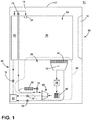
FIG. 1 is a schematic view of an exemplary washing appliance in accordance with various aspects in the present disclosure. -
FIG. 2 is a diagram of a recirculation circuit in the washing appliance ofFIG. 1 . -
FIG. 3 illustrates the exemplary washing appliance ofFIG. 1 in the form of a dishwasher. -
FIG. 4 illustrates the exemplary washing appliance ofFIG. 1 in the form of a clothes washer. -
FIG. 1 is a schematic illustration of awashing appliance 10, which will not be described in detail except as necessary for a complete understanding of the disclosure. It should be understood that thewashing appliance 10 can include a clothes washer or dishwasher, and that the various aspects in the present disclosure can be used in any suitable washing appliance, including a vertical-axis clothes washer, horizontal-axis clothes washer, combination washer-dryer, freestanding dishwasher, or under-counter dishwasher, in non-limiting examples. - The
washing appliance 10 can include acabinet 12 defining an interior and an access opening 18 of thewashing appliance 10, atub 14 provided within thecabinet 12 and at least partially defining a treatingchamber 16 for receiving articles for treatment, such as dishes or laundry. Adoor assembly 20 can be mounted to thecabinet 12 to selectively open and close the access opening 18 of thetub 14 while also providing access to the treatingchamber 16 for the loading and unloading of the items. Thedoor assembly 20 can be hingedly connected with thecabinet 12 or slidingly attached to a drawer slide system to selectively provide access to the treatingchamber 16. - The
washing appliance 10 can further include afluid circuit 29 including the treatingchamber 16, at least onesprayer 31, asump 32, and adrain pump 33. Thefluid circuit 29 is illustrated herein as arecirculation circuit 30 also having arecirculation pump 34 and areuse tank 35. Thesprayer 31 can provide water to the treatingchamber 16, after which the water can flow into thesump 32 where it can be collected in thereuse tank 35 and directed back to thesprayer 31 by therecirculation pump 34. It is also contemplated that thedrain pump 33 can be fluidly coupled to thereuse tank 35 to drain collected water. In another example thefluid circuit 29 can optionally be a non-recirculating fluid circuit, where water can flow from thesprayer 31 into the treatingchamber 16 and move into thesump 32 before being drained by thedrain pump 33. - A
filtration system 40 for thewashing appliance 10 can be fluidly coupled to thecircuit 30 and can include acoarse filter 41, aparticle filter 42, an electrocoagulation unit (EU) 50, and a centrifugal separator (CS) 60. Thecoarse filter 41 can include a wire or plastic mesh capable of capturing large particles/soils, while theparticle filter 42 can include an ultrafiltration filter or nanofiltration filter capable of trapping smaller particles down to 1.0 µm or 1.0 nm in size, respectively. Thecentrifugal separator 60, illustrated here as a horizontal centrifuge and seen in further detail inFIG. 2 , can include a cone-shaped body 61 andparticle reservoir 62. Thebody 61 can rotate about a central axis and form a rotating column of water at a speed such that soil particles of a predetermined size or density within the water can undergo centrifugation, moving outward for collection in theparticle reservoir 62. Theelectrocoagulation unit 50, also seen in further detail inFIG. 2 , can include any standard/known EU wherein achamber 51 containing a series of charged plates/electrodes 52 can be used to apply an electrical charge to water in the chamber. In a preferred example theelectrodes 52 can be made of graphite, however any material suitable for the electrode environment can be used, including aluminum. In operation, smaller dissolved soils in the EU 50, in non-limiting examples such as particles in colloidal suspension or oxidized metal ions, can coagulate and form larger particles which can be more easily removed by thecentrifugal separator 60. - The
filtration system 40 can be fluidly coupled to thecircuit 30 such that theelectrocoagulation unit 50 is positioned upstream of thecentrifugal separator 60. There can be a water shear present within therecirculation pump 34 that can break apart coagulated soils, and in a preferred embodiment therecirculation pump 34 can be positioned upstream of both the CS 60 and EU 50 so as not to counter the action of theelectrocoagulation unit 50. Thecoarse filter 41 can be positioned between the treatingchamber 16 andsump 32, and theparticle filter 42 can be positioned on a separate fluid branch wherein a portion of the water in thecircuit 30 can flow through theparticle filter 42 as shown. Theparticle filter 42 can be placed downstream of thecentrifugal separator 60 in a non-limiting example. - In addition, a valve or set of
valves 70 can be coupled to therecirculation circuit 30. Avalve 70 can be connected to theparticle reservoir 62 to selectively remove soils collected in thereservoir 62, or connected to thedrain pump 33 to selectively drain water from the treatingchamber 16 orreuse tank 35, or connected to theparticle filter 42 to selectively remove additional soils from the water, in non-limiting examples. Thevalves 70 can optionally be used to selectively direct water to thereuse tank 35. -
FIG. 2 illustrates the circuit, illustrated here as therecirculation circuit 30. In operation, liquid can be supplied to the treatingchamber 16 through thesprayer 31, after which it flows through thesump 32,particle filter 42 and optionally into thereuse tank 35, and therecirculation pump 34 can also return the liquid back into the treatingchamber 16. In addition, water from the treatingchamber 16 can optionally be drained by thedrain pump 33. Therecirculation pump 34 can also direct at least a portion of the supplied liquid, or at least a portion of the recirculated liquid, to theelectrocoagulation unit 50 in order to coagulate soils into larger particles. The liquid and coagulated particles can then move into thecentrifugal separator 60, where the coagulated particles can be collected in theparticle reservoir 62 and drained by thedrain pump 33 while the purified liquid can move into thereuse tank 35. At least a portion of the purified liquid from thecentrifugal separator 60 can also be directed through theparticle filter 42 to remove particles of a size small enough to remain in the water during centrifugation. - It is contemplated that during a wash cycle, the
electrocoagulation unit 50 can be switched off to prevent any undesired breakdown of treating chemistry in the wash liquor such that water, treating chemistry, and soils can flow through the EU 50 and remove buildup on the electrodes. Thecentrifugal separator 60 downstream of the EU 50 can remove soils, treating chemistry, and electrode buildup such that water flowing through therecirculation circuit 30 during a wash phase can be of sufficient quality to be used in a later rinse phase. - It is further contemplated that during a rinse cycle, the
electrocoagulation unit 50 can be switched on to aid thecentrifugal separator 60 in purifying the water in therecirculation circuit 30. The polarity of theelectrodes 52 in the EU 50 can be repeatedly reversed to prevent buildup on theelectrodes 52, and in one non-limiting example the polarity can be reversed every sixty seconds. Water can then flow into thecentrifugal separator 60 in order to collect coagulated soils as described above. - It can be appreciated that size of the particles generated by the
electrocoagulation unit 50 can be selected by modifying operating parameters of theelectrocoagulation unit 50 such as, but not limited to, the electrode voltage or rate of polarity reversal. Similarly, the efficacy of particle settling by thecentrifugal separator 60 can depend on parameters such as, but not limited to, the size, mass, or density of soil particles, or the rotational velocity of the liquid. Particles with a larger mass or density compared to the surrounding liquid can settle out of the liquid at a faster rate, and it can therefore be advantageous to coagulate smaller soil particles into larger ones by operating theelectrocoagulation unit 50 before directing liquid and soils into thecentrifugal separator 60 for more efficient removal of soils. In this manner, the larger soils can be removed from the liquid by theelectrocoagulation unit 50 andcentrifugal separator 60 while smaller soils can be collected by theparticle filter 42, preventing unnecessary clogging of theparticle filter 42 by larger soil particles in the liquid and extending the useful lifetime of theparticle filter 42. - It can be further appreciated that purifying wash water for use in a rinse cycle, or purifying rinse water during a rinse cycle, can allow for a reduction in total water usage by the
washing appliance 10 which can also reduce the cost to the consumer for operating thewashing appliance 10. - Referring now to
FIG. 3 , another washing appliance is illustrated in the form of a dishwasher 111. The dishwasher 111 is similar to thewashing appliance 10; therefore, like parts will be identified with like numerals increased by 100, with it being understood that the description of the like parts of thewashing appliance 10 applies to the dishwasher 111, unless otherwise noted. - In the example of
FIG. 3 , the dishwasher 111 can include acabinet 112 defining an interior of the dishwasher 111 and including a frame, with or without panels mounted to the frame. An open-faced tub 114 can be provided within thecabinet 112 and can at least partially define a treatingchamber 116, having an open face, for washing dishes. Adoor assembly 120 can be movably mounted to the dishwasher 111 for movement between opened and closed positions to selectively open and close the open face of thetub 114. Thus, the door assembly provides accessibility to the treatingchamber 116 for the loading and unloading of dishes or other washable items. - It should be appreciated that the
door assembly 120 can be secured to the lower front edge of thecabinet 112 or to the lower front edge of thetub 114 via a hinge assembly (not shown) configured to pivot thedoor assembly 120. When thedoor assembly 120 is closed, user access to the treatingchamber 116 can be prevented, whereas user access to the treatingchamber 116 can be permitted when thedoor assembly 120 is open. - Dish holders, illustrated in the form of upper and
lower dish racks chamber 116 and receive dishes for washing. The upper andlower racks chamber 116 for ease of loading and unloading. Other dish holders can be provided, such as a silverware basket. As used in this description, the term "dish(es)" is intended to be generic to any item, single or plural, that can be treated in the dishwasher 111, including, without limitation, dishes, plates, pots, bowls, pans, glassware, and silverware. - A set of sprayers 131 provided for spraying liquid in the treating
chamber 116 and is provided in the form of a firstlower spray assembly 131A, a secondlower spray assembly 131B, a rotating mid-levelspray arm assembly 131C, and/or an upperspray arm assembly 131D.Upper sprayer 131D, mid-levelrotatable sprayer 131C and lowerrotatable sprayer 131A can be located, respectively, above theupper rack 180, beneath theupper rack 180, and beneath thelower rack 181 and are illustrated as rotating spray arms. The secondlower spray assembly 131B is illustrated as being located adjacent thelower dish rack 181 toward the rear of the treatingchamber 116. - A
recirculation circuit 130 can be provided for recirculating liquid from the treatingchamber 116 to the set of sprayers 131. Therecirculation circuit 130 can include asump 132, adrain pump 133, arecirculation pump 134, and areuse tank 135. Thesump 132 can collect the liquid sprayed in the treatingchamber 116 and can be formed by a sloped or recess portion of a bottom wall of thetub 114. Thedrain pump 133 can draw liquid from thesump 132 and pump the liquid out of thedishwasher 110 to a household drain line (not shown). Therecirculation pump 134 can draw liquid from thesump 132, and the liquid can be simultaneously or selectively pumped through asupply tube 182 to the set of sprayers 131 for selective spraying. While not shown, a liquid supply system can include a water supply conduit coupled with a household water supply for supplying water to the treatingchamber 116. - A
filtration system 140 can be fluidly coupled to therecirculation circuit 130 and include acoarse filter 141, aparticle filter 142, an electrocoagulation unit (EU) 150 and a centrifugal separator (CS) 160. A set ofvalves 170 can also be coupled to therecirculation circuit 130 to selectively remove soils collected theCS 160, selectively supply water to or drain water from the treatingchamber 116 orreuse tank 135, or selectively remove additional soils from the water via theparticle filter 142, in non-limiting examples. It can be appreciated that operation of theEU 150 andCS 160 can coagulate and remove soils within therecirculation circuit 130 in a manner similar to that described inFIG. 2 . - Turning to
FIG. 4 , another washing appliance is illustrated in the form of aclothes washer 211. Theclothes washer 211 is similar to thewashing appliance 10; therefore, like parts will be identified with like numerals increased by 100, with it being understood that the description of the like parts of thewashing appliance 10 applies to theclothes washer 211, unless otherwise noted. - The washing appliance of
FIG. 4 is illustrated as aclothes washer 211, which can include a structural support system including acabinet 212 which defines a housing within which a laundry holding system resides. Thecabinet 212 can be a housing having a chassis and/or a frame, defining an interior enclosing components typically found in a conventional washing machine, such as motors, pumps, fluid lines, controls, sensors, transducers, and the like. Such components will not be described further herein except as necessary for a complete understanding of the disclosure. - The laundry holding system includes a
tub 214 supported within thecabinet 212 by a suitable suspension system and adrum 213 provided within thetub 214, thedrum 213 defining at least a portion of alaundry treating chamber 216. Thedrum 213 can include a plurality ofperforations 219 such that liquid can flow between thetub 214 and thedrum 213 through theperforations 219. A plurality ofbaffles 222 can be disposed on an inner surface of thedrum 213 to lift the laundry load received in the treatingchamber 216 while thedrum 213 rotates. It is also within the scope of the disclosure for the laundry holding system to include only a tub with the tub defining the laundry treating chamber. - The laundry holding system can further include a door 220 which can be movably mounted to the
cabinet 212 to selectively close both thetub 214 and thedrum 213. A bellows 226 can couple an open face of thetub 214 with thecabinet 212, with the door 220 sealing against the bellows 226 when the door 220 closes thetub 214. - The
clothes washer 211 can further include asuspension system 228 for dynamically suspending the laundry holding system within the structural support system. - The
clothes washer 211 can further include a liquid supply system for supplying water to theclothes washer 211 for use in treating laundry during a cycle of operation. The liquid supply system can include a source of water, such as ahousehold water supply 239, which can includeseparate valves inlet conduit 245 directly to thetub 214 by controlling first andsecond diverter mechanisms diverter mechanisms diverter mechanisms household water supply 239 can flow through theinlet conduit 245 to thefirst diverter mechanism 246 which can direct the flow of liquid to asupply conduit 252. Thesecond diverter mechanism 247 on thesupply conduit 252 can direct the flow of liquid to atub outlet conduit 254 which can be provided with a spray nozzle orsprayer 231 configured to spray the flow of liquid into thetub 214. In this manner, water from thehousehold water supply 239 can be supplied directly to thetub 214. - The
clothes washer 211 can also be provided with a dispensing system for dispensing treating chemistry to the treatingchamber 216 for use in treating the laundry according to a cycle of operation. The dispensing system can include adispenser 263 which can be a single use dispenser, a bulk dispenser or a combination of a single and bulk dispenser. - Regardless of the type of dispenser used, the
dispenser 263 can be configured to dispense a treating chemistry directly to thetub 214 or mixed with water from the liquid supply system through a dispensingoutlet conduit 264. The dispensing outlet conduit 64 can include a dispensingnozzle 266 configured to dispense the treating chemistry into thetub 214 in a desired pattern and under a desired amount of pressure. For example, the dispensingnozzle 266 can be configured to dispense a flow or stream of treating chemistry into thetub 214 by gravity, i.e. a non-pressurized stream. Water can be supplied to thedispenser 263 from thesupply conduit 252 by directing thediverter mechanism 247 to direct the flow of water to a dispensingsupply conduit 268. - Non-limiting examples of treating chemistries that can be dispensed by the dispensing system during a cycle of operation include one or more of the following: water, enzymes, fragrances, stiffness/sizing agents, wrinkle releasers/reducers, softeners, antistatic or electrostatic agents, stain repellants, water repellants, energy reduction/extraction aids, antibacterial agents, medicinal agents, vitamins, moisturizers, shrinkage inhibitors, and color fidelity agents, and combinations thereof.
- The
clothes washer 211 can also include a recirculation and drain system for recirculating liquid within the laundry holding system and draining liquid from theclothes washer 211. Liquid supplied to thetub 214 throughtub outlet conduit 254 and/or the dispensingsupply conduit 268 typically enters a space between thetub 214 and thedrum 213 and can flow by gravity to asump 232 formed in part by a lower portion of thetub 214. Thesump 232 can also be formed by asump conduit 272 that can fluidly couple the lower portion of thetub 214 to apump assembly 274. Thepump assembly 274 can include adrain pump 233 directing liquid to adrain conduit 276, which can drain the liquid from theclothes washer 211. Thepump assembly 274 can also include arecirculation pump 234 directing liquid to a recirculation conduit 278 or reuse tank 235 which can terminate at arecirculation inlet 279. Therecirculation inlet 279 can direct the liquid from the recirculation conduit 278 into thedrum 213. Therecirculation inlet 279 can introduce the liquid into thedrum 213 in any suitable manner, such as by spraying, dripping, or providing a steady flow of liquid. In this manner, liquid provided to thetub 214, with or without treating chemistry can be recirculated into the treatingchamber 216 for treating the laundry within. In this manner the treatingchamber 216,sprayer 231,sump 232,drain pump 233,recirculation pump 234, and reuse tank 235 can define at least a portion of arecirculation circuit 230 in theclothes washer 211. - The
clothes washer 211 can further include afiltration system 240 fluidly coupled to therecirculation circuit 230. Thefiltration system 240 include acoarse filter 241, aparticle filter 242, an electrocoagulation unit (EU) 250 and a centrifugal separator (CS) 260. A set ofvalves 270 can also be coupled to therecirculation circuit 130 to selectively remove soils collected theCS 260, selectively supply water to or drain water from the treatingchamber 216 or reuse tank 235, or selectively remove additional soils from the water via theparticle filter 242, in non-limiting examples. It can be appreciated that operation of theEU 250 andCS 260 can coagulate and remove soils within therecirculation circuit 230 in a manner similar to that described inFIG. 2 . - The liquid supply and/or recirculation and drain system can be provided with a heating system which can include one or more devices for heating laundry and/or liquid supplied to the
tub 214, such as asteam generator 283 and/or asump heater 285. Liquid from thehousehold water supply 239 can be provided to thesteam generator 283 through theinlet conduit 245 by controlling thefirst diverter mechanism 246 to direct the flow of liquid to asteam supply conduit 286. Steam generated by thesteam generator 283 can be supplied to thetub 214 through asteam outlet conduit 287. Thesteam generator 283 can be any suitable type of steam generator such as a flow through steam generator or a tank-type steam generator. Alternatively, thesump heater 285 can be used to generate steam in place of or in addition to thesteam generator 283. In addition or alternatively to generating steam, thesteam generator 283 and/orsump heater 285 can be used to heat the laundry and/or liquid within thetub 214 as part of a cycle of operation. - Additionally, the liquid supply and recirculation and drain system can differ from the configuration shown in
FIG. 1 , such as by inclusion of other valves, conduits, treating chemistry dispensers, sensors, such as water level sensors and temperature sensors, and the like, to control the flow of liquid through theclothes washer 211 and for the introduction of more than one type of treating chemistry. - The
clothes washer 211 also includes a drive system for rotating thedrum 213 within thetub 214. The drive system can include amotor 288, which can be directly coupled with thedrum 213 through adrive shaft 290 to rotate thedrum 213 about a rotational axis during a cycle of operation. Themotor 288 can be a brushless permanent magnet (BPM) motor having astator 292 and arotor 294. Alternately, themotor 288 can be coupled to thedrum 213 through a belt and a drive shaft to rotate thedrum 213, as is known in the art. Other motors, such as an induction motor or a permanent split capacitor (PSC) motor, can also be used. Themotor 288 can rotate thedrum 213 at various speeds in either rotational direction. - The
clothes washer 211 also includes a control system for controlling the operation of theclothes washer 211 to implement one or more cycles of operation. The control system can include acontroller 296 located within thecabinet 212 and auser interface 298 that is operably coupled with thecontroller 296. Theuser interface 298 can include one or more knobs, dials, switches, displays, touch screens and the like for communicating with the user, such as to receive input and provide output. The user can enter different types of information including, without limitation, cycle selection and cycle parameters, such as cycle options. - The
controller 296 can include the machine controller and any additional controllers provided for controlling any of the components of theclothes washer 211. For example, the controller 96 can include the machine controller and a motor controller. Many known types of controllers can be used for thecontroller 296. It is contemplated that the controller is a microprocessor-based controller that implements control software and sends/receives one or more electrical signals to/from each of the various working components to effect the control software. As an example, proportional control (P), proportional integral control (PI), and proportional derivative control (PD), or a combination thereof, a proportional integral derivative control (PID control), can be used to control the various components. - To the extent not already described, the different features and structures of the various embodiments can be used in combination with each other as desired. That one feature is not be illustrated in all of the embodiments is not meant to be construed that it cannot be, but is done for brevity of description. Thus, the various features of the different embodiments can be mixed and matched as desired to form new embodiments, whether or not the new embodiments are expressly described.
- While the disclosure has been specifically described in connection with certain specific embodiments thereof, it is to be understood that this is by way of illustration and not of limitation. Reasonable variation and modification are possible within the scope of the forgoing disclosure and drawings which is defined in the appended claims. In addition to the concepts covered by the below claims, the following concepts can also provide the basis for claims in any possible combination:
- The method as described herein where the coagulating comprising coagulating particles of a size smaller than the predetermined size.
- The method as described herein further comprising after the centrifugally removing and before the coagulation, filtering a portion of the liquid to remove particles less than the predetermined size.
- The method as described herein further comprising storing at least some of the portion of the liquid for reuse.
- The method as described herein further comprising draining the centrifugally removed particles.
- The method as described herein further comprising using the liquid for both a wash phase and a rinse phase.
- This written description uses examples to disclose embodiments of the invention, and also to enable any person skilled in the art to practice embodiments of the invention, including making and using any devices or systems and performing any incorporated methods. The patentable scope of the invention is defined by the claims, and can include other examples that occur to those skilled in the art. Such other examples are intended to be within the scope of the claims if they have structural elements that do not differ from the literal language of the claims, or if they include equivalent structural elements with insubstantial differences from the literal languages of the claims.
Claims (15)
- A washing appliance (10) comprising:a tub (14, 114, 214) at least partially defining a treating chamber (16, 116, 216) with an access opening (18);a sprayer (31, 131, 131A, 131B, 131C, 131D, 231) emitting liquid into the treating chamber (16, 116, 216);a recirculation circuit (30, 130, 230) fluidly coupling the treating chamber (16, 116, 216) to the sprayer (31, 131, 131A, 131B, 131C, 131D, 231);a centrifugal separator (CS) (60, 160, 260) fluidly coupled to the recirculation circuit (30); andan electrocoagulation unit (EU) (50, 150, 250) fluidly coupled to the recirculation circuit (30).
- The washing appliance (10) of claim 1 further comprising a recirculation pump (34, 134, 234) fluidly coupled to the recirculation circuit (30, 130, 230).
- The washing appliance (10) of claims 1 or 2 wherein the EU (50, 150, 250) is fluidly coupled to the recirculation circuit (30) upstream of the CS (60, 160, 260).
- The washing appliance (10) of any of claims 1-3 wherein the CS (60, 160, 260) removes particles greater than a predetermined size.
- The washing appliance (10) of any of claims 1-4 wherein the EU (50, 150, 250) generates particles greater than the predetermined size.
- The washing appliance (10) of any of claims 2-5 wherein the CS (60, 160, 260) and EU (50, 150, 250) are fluidly coupled to the recirculation circuit (30, 130, 230) downstream of the recirculation pump (34, 134, 234).
- The washing appliance (10) of claim 1 wherein the CS (60, 160, 260) removes particles of a size greater than a predetermined size and the EU (50, 150, 250) generates particles greater than the predetermined size.
- The washing appliance (10) according to any of the preceding claims further comprising a particle filter (42, 142, 242) fluidly coupled to the recirculation circuit (30, 130, 230) and removing particles of a size less than the predetermined size.
- The washing appliance (10) of claim 8 wherein the particle filter (42, 142, 242) is one of an ultrafiltration or nanofiltration filter.
- The washing appliance (10) according to any of the preceding claims further comprising a reuse tank (35, 135, 235) fluidly coupled to the recirculation circuit (30, 130, 230).
- The washing appliance (10) according to any of the preceding claims wherein the CS (60, 160, 260) comprises a particle reservoir (62) storing centrifugally removed particles.
- The washing appliance (10) of claim 11 further comprising a drain pump (33, 133, 233) fluidly coupled to the particle reservoir (62).
- The washing appliance (10) according to any of the preceding claims wherein the washing appliance (10) comprises at least one of a clothes washer or a dish washer.
- A method of treating at least one of laundry or dishes in a treating chamber (16, 116, 216) of an appliance (10), the method comprising:recirculating liquid through the treating chamber (16, 116, 216);centrifugally removing particles greater than a predetermined size from the liquid during recirculation of the liquid; andcoagulating particles greater than the predetermined size in the liquid during recirculation of the liquid.
- The method of claim 14 wherein the coagulating occurs downstream of the centrifugally removing.
Applications Claiming Priority (2)
| Application Number | Priority Date | Filing Date | Title |
|---|---|---|---|
| US201762464405P | 2017-02-28 | 2017-02-28 | |
| US15/891,628 US11039728B2 (en) | 2017-02-28 | 2018-02-08 | Washing appliance having a recirculation circuit |
Publications (2)
| Publication Number | Publication Date |
|---|---|
| EP3369855A1 true EP3369855A1 (en) | 2018-09-05 |
| EP3369855B1 EP3369855B1 (en) | 2019-10-09 |
Family
ID=61231087
Family Applications (1)
| Application Number | Title | Priority Date | Filing Date |
|---|---|---|---|
| EP18157044.1A Active EP3369855B1 (en) | 2017-02-28 | 2018-02-15 | Washing appliance having a recirculation circuit |
Country Status (2)
| Country | Link |
|---|---|
| US (2) | US11039728B2 (en) |
| EP (1) | EP3369855B1 (en) |
Cited By (3)
| Publication number | Priority date | Publication date | Assignee | Title |
|---|---|---|---|---|
| EP3712320A1 (en) * | 2019-03-20 | 2020-09-23 | E.G.O. Elektro-Gerätebau GmbH | Water-conveying household appliance and method for operating same |
| CN112169435A (en) * | 2020-09-09 | 2021-01-05 | 马鞍山拓锐金属表面技术有限公司 | Waste water collection device of pressure filter for preparing solid chemical raw materials |
| CN113754028A (en) * | 2021-09-23 | 2021-12-07 | 中国环境科学研究院 | High-arsenic water body purification method based on particle size characteristics of arsenic-iron-organic matter |
Families Citing this family (6)
| Publication number | Priority date | Publication date | Assignee | Title |
|---|---|---|---|---|
| US11691899B2 (en) | 2019-12-23 | 2023-07-04 | Whirlpool Corporation | Household appliance with coagulant dosing system |
| EP4413197A4 (en) * | 2021-10-05 | 2025-06-25 | Vestel Beyaz Esya Sanayi ve Ticaret Anonim Sirketi | A washing machine with a microfiber filter assembly |
| US20230272575A1 (en) * | 2022-02-28 | 2023-08-31 | Whirlpool Corporation | Laundry treating appliance with foreign object barrier |
| US20250263882A1 (en) * | 2024-02-20 | 2025-08-21 | Haier Us Appliance Solutions, Inc. | Fluid circulation system with a filter element in a washing machine appliance |
| US12601101B2 (en) * | 2024-02-20 | 2026-04-14 | Haier Us Appliance Solutions, Inc. | Pump assembly for dispenser cleaning in a washing machine appliance |
| CN118029098B (en) * | 2024-02-26 | 2025-10-03 | 珠海格力电器股份有限公司 | A washing machine |
Citations (4)
| Publication number | Priority date | Publication date | Assignee | Title |
|---|---|---|---|---|
| JP2002119794A (en) * | 2000-10-16 | 2002-04-23 | Sharp Corp | Washing machine |
| KR100820792B1 (en) * | 2001-06-04 | 2008-04-10 | 엘지전자 주식회사 | Water purification system for rinsing water recycling in washing machine and rinsing control method using the same |
| US20130327361A1 (en) * | 2010-12-24 | 2013-12-12 | Sarmistha Biswas | Flocculation process and device |
| EP3128065A1 (en) * | 2014-03-27 | 2017-02-08 | Haier Group Corporation | Washing machine flocculation apparatus with self-cleaning function, and washing machine |
Family Cites Families (12)
| Publication number | Priority date | Publication date | Assignee | Title |
|---|---|---|---|---|
| DE4115347C2 (en) | 1991-05-10 | 1999-07-22 | Baker Hughes De Gmbh | Solid bowl screw centrifuge for classifying a solid-liquid mixture |
| US6001190A (en) | 1995-04-06 | 1999-12-14 | General Electric Company | Reduced energy cleaning appliance |
| US5770058A (en) | 1995-09-29 | 1998-06-23 | Whirlpool Corporation | Centrifugal separator |
| US5795459A (en) * | 1996-07-29 | 1998-08-18 | Sweeney; Charles T. | Apparatus and method for water purification |
| US6841058B2 (en) * | 2002-04-04 | 2005-01-11 | Brian G. Culvey | Redox bipolar cell fabric washer system |
| US7018539B2 (en) * | 2002-10-24 | 2006-03-28 | Membrane Technology And Research, Inc. | Treatment of shipboard-generated oily wastewaters |
| US8371315B2 (en) | 2008-12-17 | 2013-02-12 | Tennant Company | Washing systems incorporating charged activated liquids |
| ITTO20110162A1 (en) * | 2011-02-25 | 2012-08-26 | Indesit Co Spa | SELECTOR FOR A HOME WASHING MACHINE AND DOMESTIC WASHING MACHINE PROVIDED WITH THIS SELECTOR |
| EP2781641B1 (en) * | 2013-03-19 | 2019-10-16 | Whirlpool Corporation | Washing machine with a storage tank for reusing water and method for carrying out a water reuse step |
| WO2015021342A1 (en) * | 2013-08-09 | 2015-02-12 | University Of Pittsburgh-Of The Commonwealth System Of Higher Education | Methods and systems for treating wastewater from induced hydraulic fracturing |
| US20160183763A1 (en) * | 2013-09-13 | 2016-06-30 | Dow Global Technologies Llc | Washing machine including integral filter module |
| US9663893B2 (en) * | 2014-03-21 | 2017-05-30 | Whirlpool Corporation | Laundry treating appliance dispenser |
-
2018
- 2018-02-08 US US15/891,628 patent/US11039728B2/en active Active
- 2018-02-15 EP EP18157044.1A patent/EP3369855B1/en active Active
-
2021
- 2021-05-25 US US17/329,536 patent/US11739471B2/en active Active
Patent Citations (4)
| Publication number | Priority date | Publication date | Assignee | Title |
|---|---|---|---|---|
| JP2002119794A (en) * | 2000-10-16 | 2002-04-23 | Sharp Corp | Washing machine |
| KR100820792B1 (en) * | 2001-06-04 | 2008-04-10 | 엘지전자 주식회사 | Water purification system for rinsing water recycling in washing machine and rinsing control method using the same |
| US20130327361A1 (en) * | 2010-12-24 | 2013-12-12 | Sarmistha Biswas | Flocculation process and device |
| EP3128065A1 (en) * | 2014-03-27 | 2017-02-08 | Haier Group Corporation | Washing machine flocculation apparatus with self-cleaning function, and washing machine |
Cited By (4)
| Publication number | Priority date | Publication date | Assignee | Title |
|---|---|---|---|---|
| EP3712320A1 (en) * | 2019-03-20 | 2020-09-23 | E.G.O. Elektro-Gerätebau GmbH | Water-conveying household appliance and method for operating same |
| CN112169435A (en) * | 2020-09-09 | 2021-01-05 | 马鞍山拓锐金属表面技术有限公司 | Waste water collection device of pressure filter for preparing solid chemical raw materials |
| CN113754028A (en) * | 2021-09-23 | 2021-12-07 | 中国环境科学研究院 | High-arsenic water body purification method based on particle size characteristics of arsenic-iron-organic matter |
| CN113754028B (en) * | 2021-09-23 | 2022-10-25 | 中国环境科学研究院 | A high-arsenic water purification method based on arsenic-iron-organic matter particle size characteristics |
Also Published As
| Publication number | Publication date |
|---|---|
| US20180242814A1 (en) | 2018-08-30 |
| US20210274995A1 (en) | 2021-09-09 |
| US11739471B2 (en) | 2023-08-29 |
| EP3369855B1 (en) | 2019-10-09 |
| US11039728B2 (en) | 2021-06-22 |
Similar Documents
| Publication | Publication Date | Title |
|---|---|---|
| US11739471B2 (en) | Washing appliance having a recirculation circuit | |
| US9107559B2 (en) | Dishwasher with filter assembly | |
| US11668044B2 (en) | Method of dispensing treating chemistries in a laundry treating appliance | |
| US10813525B2 (en) | Ultra micron filter for a dishwasher | |
| EP2518204B1 (en) | Method and apparatus for dispensing treating chemistry in a laundry treating appliance | |
| US10815605B2 (en) | Laundry treating appliance having a bulk dispensing assembly | |
| US10329707B2 (en) | Laundry treating appliance with pre-filter backwashing | |
| US11578452B2 (en) | Laundry treating appliance having a treating chemistry dispenser | |
| EP2687142B1 (en) | Household dish-washing machine | |
| EP2671495A2 (en) | Rotating filter for a dishwasher | |
| US20210198834A1 (en) | Laundry treating appliance having a wash water treating assembly | |
| US20170226683A1 (en) | Laundry treating appliance dispenser | |
| US20260028763A1 (en) | Dispensing system for a laundry treating appliance | |
| EP3344109B1 (en) | Detergent dispensing device for a dishwasher | |
| US10351985B2 (en) | Method and apparatus for rinsing laundry in a laundry treating appliance | |
| US12091804B2 (en) | Laundry treating appliance and method of dispensing | |
| EP2611351B1 (en) | Control method for a dishwasher | |
| EP4212665A1 (en) | Laundry treating appliance having a condenser assembly |
Legal Events
| Date | Code | Title | Description |
|---|---|---|---|
| PUAI | Public reference made under article 153(3) epc to a published international application that has entered the european phase |
Free format text: ORIGINAL CODE: 0009012 |
|
| STAA | Information on the status of an ep patent application or granted ep patent |
Free format text: STATUS: THE APPLICATION HAS BEEN PUBLISHED |
|
| AK | Designated contracting states |
Kind code of ref document: A1 Designated state(s): AL AT BE BG CH CY CZ DE DK EE ES FI FR GB GR HR HU IE IS IT LI LT LU LV MC MK MT NL NO PL PT RO RS SE SI SK SM TR |
|
| AX | Request for extension of the european patent |
Extension state: BA ME |
|
| STAA | Information on the status of an ep patent application or granted ep patent |
Free format text: STATUS: REQUEST FOR EXAMINATION WAS MADE |
|
| 17P | Request for examination filed |
Effective date: 20190305 |
|
| RBV | Designated contracting states (corrected) |
Designated state(s): AL AT BE BG CH CY CZ DE DK EE ES FI FR GB GR HR HU IE IS IT LI LT LU LV MC MK MT NL NO PL PT RO RS SE SI SK SM TR |
|
| GRAP | Despatch of communication of intention to grant a patent |
Free format text: ORIGINAL CODE: EPIDOSNIGR1 |
|
| STAA | Information on the status of an ep patent application or granted ep patent |
Free format text: STATUS: GRANT OF PATENT IS INTENDED |
|
| INTG | Intention to grant announced |
Effective date: 20190725 |
|
| GRAS | Grant fee paid |
Free format text: ORIGINAL CODE: EPIDOSNIGR3 |
|
| GRAA | (expected) grant |
Free format text: ORIGINAL CODE: 0009210 |
|
| STAA | Information on the status of an ep patent application or granted ep patent |
Free format text: STATUS: THE PATENT HAS BEEN GRANTED |
|
| AK | Designated contracting states |
Kind code of ref document: B1 Designated state(s): AL AT BE BG CH CY CZ DE DK EE ES FI FR GB GR HR HU IE IS IT LI LT LU LV MC MK MT NL NO PL PT RO RS SE SI SK SM TR |
|
| REG | Reference to a national code |
Ref country code: GB Ref legal event code: FG4D |
|
| REG | Reference to a national code |
Ref country code: CH Ref legal event code: EP |
|
| REG | Reference to a national code |
Ref country code: DE Ref legal event code: R096 Ref document number: 602018000806 Country of ref document: DE |
|
| REG | Reference to a national code |
Ref country code: IE Ref legal event code: FG4D |
|
| REG | Reference to a national code |
Ref country code: AT Ref legal event code: REF Ref document number: 1188938 Country of ref document: AT Kind code of ref document: T Effective date: 20191115 |
|
| REG | Reference to a national code |
Ref country code: NL Ref legal event code: MP Effective date: 20191009 |
|
| REG | Reference to a national code |
Ref country code: LT Ref legal event code: MG4D |
|
| REG | Reference to a national code |
Ref country code: AT Ref legal event code: MK05 Ref document number: 1188938 Country of ref document: AT Kind code of ref document: T Effective date: 20191009 |
|
| PG25 | Lapsed in a contracting state [announced via postgrant information from national office to epo] |
Ref country code: AT Free format text: LAPSE BECAUSE OF FAILURE TO SUBMIT A TRANSLATION OF THE DESCRIPTION OR TO PAY THE FEE WITHIN THE PRESCRIBED TIME-LIMIT Effective date: 20191009 Ref country code: NL Free format text: LAPSE BECAUSE OF FAILURE TO SUBMIT A TRANSLATION OF THE DESCRIPTION OR TO PAY THE FEE WITHIN THE PRESCRIBED TIME-LIMIT Effective date: 20191009 Ref country code: SE Free format text: LAPSE BECAUSE OF FAILURE TO SUBMIT A TRANSLATION OF THE DESCRIPTION OR TO PAY THE FEE WITHIN THE PRESCRIBED TIME-LIMIT Effective date: 20191009 Ref country code: LV Free format text: LAPSE BECAUSE OF FAILURE TO SUBMIT A TRANSLATION OF THE DESCRIPTION OR TO PAY THE FEE WITHIN THE PRESCRIBED TIME-LIMIT Effective date: 20191009 Ref country code: FI Free format text: LAPSE BECAUSE OF FAILURE TO SUBMIT A TRANSLATION OF THE DESCRIPTION OR TO PAY THE FEE WITHIN THE PRESCRIBED TIME-LIMIT Effective date: 20191009 Ref country code: BG Free format text: LAPSE BECAUSE OF FAILURE TO SUBMIT A TRANSLATION OF THE DESCRIPTION OR TO PAY THE FEE WITHIN THE PRESCRIBED TIME-LIMIT Effective date: 20200109 Ref country code: GR Free format text: LAPSE BECAUSE OF FAILURE TO SUBMIT A TRANSLATION OF THE DESCRIPTION OR TO PAY THE FEE WITHIN THE PRESCRIBED TIME-LIMIT Effective date: 20200110 Ref country code: PT Free format text: LAPSE BECAUSE OF FAILURE TO SUBMIT A TRANSLATION OF THE DESCRIPTION OR TO PAY THE FEE WITHIN THE PRESCRIBED TIME-LIMIT Effective date: 20200210 Ref country code: NO Free format text: LAPSE BECAUSE OF FAILURE TO SUBMIT A TRANSLATION OF THE DESCRIPTION OR TO PAY THE FEE WITHIN THE PRESCRIBED TIME-LIMIT Effective date: 20200109 Ref country code: ES Free format text: LAPSE BECAUSE OF FAILURE TO SUBMIT A TRANSLATION OF THE DESCRIPTION OR TO PAY THE FEE WITHIN THE PRESCRIBED TIME-LIMIT Effective date: 20191009 Ref country code: LT Free format text: LAPSE BECAUSE OF FAILURE TO SUBMIT A TRANSLATION OF THE DESCRIPTION OR TO PAY THE FEE WITHIN THE PRESCRIBED TIME-LIMIT Effective date: 20191009 Ref country code: PL Free format text: LAPSE BECAUSE OF FAILURE TO SUBMIT A TRANSLATION OF THE DESCRIPTION OR TO PAY THE FEE WITHIN THE PRESCRIBED TIME-LIMIT Effective date: 20191009 |
|
| PG25 | Lapsed in a contracting state [announced via postgrant information from national office to epo] |
Ref country code: RS Free format text: LAPSE BECAUSE OF FAILURE TO SUBMIT A TRANSLATION OF THE DESCRIPTION OR TO PAY THE FEE WITHIN THE PRESCRIBED TIME-LIMIT Effective date: 20191009 Ref country code: HR Free format text: LAPSE BECAUSE OF FAILURE TO SUBMIT A TRANSLATION OF THE DESCRIPTION OR TO PAY THE FEE WITHIN THE PRESCRIBED TIME-LIMIT Effective date: 20191009 Ref country code: IS Free format text: LAPSE BECAUSE OF FAILURE TO SUBMIT A TRANSLATION OF THE DESCRIPTION OR TO PAY THE FEE WITHIN THE PRESCRIBED TIME-LIMIT Effective date: 20200224 |
|
| PG25 | Lapsed in a contracting state [announced via postgrant information from national office to epo] |
Ref country code: AL Free format text: LAPSE BECAUSE OF FAILURE TO SUBMIT A TRANSLATION OF THE DESCRIPTION OR TO PAY THE FEE WITHIN THE PRESCRIBED TIME-LIMIT Effective date: 20191009 |
|
| REG | Reference to a national code |
Ref country code: DE Ref legal event code: R097 Ref document number: 602018000806 Country of ref document: DE |
|
| PG2D | Information on lapse in contracting state deleted |
Ref country code: IS |
|
| PG25 | Lapsed in a contracting state [announced via postgrant information from national office to epo] |
Ref country code: CZ Free format text: LAPSE BECAUSE OF FAILURE TO SUBMIT A TRANSLATION OF THE DESCRIPTION OR TO PAY THE FEE WITHIN THE PRESCRIBED TIME-LIMIT Effective date: 20191009 Ref country code: RO Free format text: LAPSE BECAUSE OF FAILURE TO SUBMIT A TRANSLATION OF THE DESCRIPTION OR TO PAY THE FEE WITHIN THE PRESCRIBED TIME-LIMIT Effective date: 20191009 Ref country code: DK Free format text: LAPSE BECAUSE OF FAILURE TO SUBMIT A TRANSLATION OF THE DESCRIPTION OR TO PAY THE FEE WITHIN THE PRESCRIBED TIME-LIMIT Effective date: 20191009 Ref country code: EE Free format text: LAPSE BECAUSE OF FAILURE TO SUBMIT A TRANSLATION OF THE DESCRIPTION OR TO PAY THE FEE WITHIN THE PRESCRIBED TIME-LIMIT Effective date: 20191009 Ref country code: IS Free format text: LAPSE BECAUSE OF FAILURE TO SUBMIT A TRANSLATION OF THE DESCRIPTION OR TO PAY THE FEE WITHIN THE PRESCRIBED TIME-LIMIT Effective date: 20200209 |
|
| PLBE | No opposition filed within time limit |
Free format text: ORIGINAL CODE: 0009261 |
|
| STAA | Information on the status of an ep patent application or granted ep patent |
Free format text: STATUS: NO OPPOSITION FILED WITHIN TIME LIMIT |
|
| PG25 | Lapsed in a contracting state [announced via postgrant information from national office to epo] |
Ref country code: SK Free format text: LAPSE BECAUSE OF FAILURE TO SUBMIT A TRANSLATION OF THE DESCRIPTION OR TO PAY THE FEE WITHIN THE PRESCRIBED TIME-LIMIT Effective date: 20191009 Ref country code: SM Free format text: LAPSE BECAUSE OF FAILURE TO SUBMIT A TRANSLATION OF THE DESCRIPTION OR TO PAY THE FEE WITHIN THE PRESCRIBED TIME-LIMIT Effective date: 20191009 |
|
| 26N | No opposition filed |
Effective date: 20200710 |
|
| REG | Reference to a national code |
Ref country code: BE Ref legal event code: MM Effective date: 20200229 |
|
| PG25 | Lapsed in a contracting state [announced via postgrant information from national office to epo] |
Ref country code: LU Free format text: LAPSE BECAUSE OF NON-PAYMENT OF DUE FEES Effective date: 20200215 Ref country code: MC Free format text: LAPSE BECAUSE OF FAILURE TO SUBMIT A TRANSLATION OF THE DESCRIPTION OR TO PAY THE FEE WITHIN THE PRESCRIBED TIME-LIMIT Effective date: 20191009 |
|
| PG25 | Lapsed in a contracting state [announced via postgrant information from national office to epo] |
Ref country code: SI Free format text: LAPSE BECAUSE OF FAILURE TO SUBMIT A TRANSLATION OF THE DESCRIPTION OR TO PAY THE FEE WITHIN THE PRESCRIBED TIME-LIMIT Effective date: 20191009 |
|
| PG25 | Lapsed in a contracting state [announced via postgrant information from national office to epo] |
Ref country code: IE Free format text: LAPSE BECAUSE OF NON-PAYMENT OF DUE FEES Effective date: 20200215 |
|
| PG25 | Lapsed in a contracting state [announced via postgrant information from national office to epo] |
Ref country code: BE Free format text: LAPSE BECAUSE OF NON-PAYMENT OF DUE FEES Effective date: 20200229 |
|
| PG25 | Lapsed in a contracting state [announced via postgrant information from national office to epo] |
Ref country code: CH Free format text: LAPSE BECAUSE OF NON-PAYMENT OF DUE FEES Effective date: 20210228 Ref country code: LI Free format text: LAPSE BECAUSE OF NON-PAYMENT OF DUE FEES Effective date: 20210228 |
|
| PG25 | Lapsed in a contracting state [announced via postgrant information from national office to epo] |
Ref country code: TR Free format text: LAPSE BECAUSE OF FAILURE TO SUBMIT A TRANSLATION OF THE DESCRIPTION OR TO PAY THE FEE WITHIN THE PRESCRIBED TIME-LIMIT Effective date: 20191009 Ref country code: MT Free format text: LAPSE BECAUSE OF FAILURE TO SUBMIT A TRANSLATION OF THE DESCRIPTION OR TO PAY THE FEE WITHIN THE PRESCRIBED TIME-LIMIT Effective date: 20191009 Ref country code: CY Free format text: LAPSE BECAUSE OF FAILURE TO SUBMIT A TRANSLATION OF THE DESCRIPTION OR TO PAY THE FEE WITHIN THE PRESCRIBED TIME-LIMIT Effective date: 20191009 |
|
| PG25 | Lapsed in a contracting state [announced via postgrant information from national office to epo] |
Ref country code: MK Free format text: LAPSE BECAUSE OF FAILURE TO SUBMIT A TRANSLATION OF THE DESCRIPTION OR TO PAY THE FEE WITHIN THE PRESCRIBED TIME-LIMIT Effective date: 20191009 |
|
| P01 | Opt-out of the competence of the unified patent court (upc) registered |
Effective date: 20230522 |
|
| PGFP | Annual fee paid to national office [announced via postgrant information from national office to epo] |
Ref country code: DE Payment date: 20240228 Year of fee payment: 7 Ref country code: GB Payment date: 20240220 Year of fee payment: 7 |
|
| PGFP | Annual fee paid to national office [announced via postgrant information from national office to epo] |
Ref country code: IT Payment date: 20240222 Year of fee payment: 7 Ref country code: FR Payment date: 20240226 Year of fee payment: 7 |
|
| REG | Reference to a national code |
Ref country code: DE Ref legal event code: R119 Ref document number: 602018000806 Country of ref document: DE |
|
| GBPC | Gb: european patent ceased through non-payment of renewal fee |
Effective date: 20250215 |
|
| PG25 | Lapsed in a contracting state [announced via postgrant information from national office to epo] |
Ref country code: DE Free format text: LAPSE BECAUSE OF NON-PAYMENT OF DUE FEES Effective date: 20250902 |
|
| PG25 | Lapsed in a contracting state [announced via postgrant information from national office to epo] |
Ref country code: GB Free format text: LAPSE BECAUSE OF NON-PAYMENT OF DUE FEES Effective date: 20250215 |
|
| PG25 | Lapsed in a contracting state [announced via postgrant information from national office to epo] |
Ref country code: IT Free format text: LAPSE BECAUSE OF NON-PAYMENT OF DUE FEES Effective date: 20250215 Ref country code: FR Free format text: LAPSE BECAUSE OF NON-PAYMENT OF DUE FEES Effective date: 20250228 |