EP3369661B1 - System and method for detecting and removing moisture in an aircraft - Google Patents
System and method for detecting and removing moisture in an aircraft Download PDFInfo
- Publication number
- EP3369661B1 EP3369661B1 EP18158096.0A EP18158096A EP3369661B1 EP 3369661 B1 EP3369661 B1 EP 3369661B1 EP 18158096 A EP18158096 A EP 18158096A EP 3369661 B1 EP3369661 B1 EP 3369661B1
- Authority
- EP
- European Patent Office
- Prior art keywords
- aircraft
- dry gas
- moisture
- board
- moisture detection
- Prior art date
- Legal status (The legal status is an assumption and is not a legal conclusion. Google has not performed a legal analysis and makes no representation as to the accuracy of the status listed.)
- Active
Links
Images
Classifications
-
- B—PERFORMING OPERATIONS; TRANSPORTING
- B64—AIRCRAFT; AVIATION; COSMONAUTICS
- B64F—GROUND OR AIRCRAFT-CARRIER-DECK INSTALLATIONS SPECIALLY ADAPTED FOR USE IN CONNECTION WITH AIRCRAFT; DESIGNING, MANUFACTURING, ASSEMBLING, CLEANING, MAINTAINING OR REPAIRING AIRCRAFT, NOT OTHERWISE PROVIDED FOR; HANDLING, TRANSPORTING, TESTING OR INSPECTING AIRCRAFT COMPONENTS, NOT OTHERWISE PROVIDED FOR
- B64F5/00—Designing, manufacturing, assembling, cleaning, maintaining or repairing aircraft, not otherwise provided for; Handling, transporting, testing or inspecting aircraft components, not otherwise provided for
- B64F5/40—Maintaining or repairing aircraft
-
- B—PERFORMING OPERATIONS; TRANSPORTING
- B64—AIRCRAFT; AVIATION; COSMONAUTICS
- B64F—GROUND OR AIRCRAFT-CARRIER-DECK INSTALLATIONS SPECIALLY ADAPTED FOR USE IN CONNECTION WITH AIRCRAFT; DESIGNING, MANUFACTURING, ASSEMBLING, CLEANING, MAINTAINING OR REPAIRING AIRCRAFT, NOT OTHERWISE PROVIDED FOR; HANDLING, TRANSPORTING, TESTING OR INSPECTING AIRCRAFT COMPONENTS, NOT OTHERWISE PROVIDED FOR
- B64F1/00—Ground or aircraft-carrier-deck installations
- B64F1/36—Other airport installations
- B64F1/362—Installations for supplying conditioned air to parked aircraft
-
- B—PERFORMING OPERATIONS; TRANSPORTING
- B64—AIRCRAFT; AVIATION; COSMONAUTICS
- B64F—GROUND OR AIRCRAFT-CARRIER-DECK INSTALLATIONS SPECIALLY ADAPTED FOR USE IN CONNECTION WITH AIRCRAFT; DESIGNING, MANUFACTURING, ASSEMBLING, CLEANING, MAINTAINING OR REPAIRING AIRCRAFT, NOT OTHERWISE PROVIDED FOR; HANDLING, TRANSPORTING, TESTING OR INSPECTING AIRCRAFT COMPONENTS, NOT OTHERWISE PROVIDED FOR
- B64F5/00—Designing, manufacturing, assembling, cleaning, maintaining or repairing aircraft, not otherwise provided for; Handling, transporting, testing or inspecting aircraft components, not otherwise provided for
- B64F5/60—Testing or inspecting aircraft components or systems
Definitions
- the claimed invention relates generally to a system and method for detecting and removing moisture in an aircraft and, more particularly, for detecting and removing moisture within inaccessible areas of an aircraft to prevent corrosion from occurring in such inaccessible areas.
- US 2010/087957 in accordance with its abstract, states a system and methods for the storage, and preservation of mechanical assets, including collectable automobiles, small airplanes and watercraft in a storage unit.
- the storage unit includes a plurality of asset modules.
- the volume of each asset module is variable.
- the atmosphere of each asset module may be controlled by a control system.
- Control of the atmosphere of each asset module includes control of parameters including the type of gas each atmosphere is composed of and the temperature, the pressure and relative humidity of each atmosphere. These parameters may be monitored and controlled from a remote location.
- WO 2006/012266 in accordance with its abstract, states a mobile platform comprising at least one mobile platform system that includes a processor, a structure, and an SHM system.
- the SHM system also includes a processor as well as a structural sensor.
- the SHM processor is separate from the mobile platform system processor.
- the mobile platform includes a flight control system, a maintenance information system, and an IVHM system.
- the SHM system may receive parameters from the flight control system and calculate loads therefrom.
- the sensor may be a structural load sensor, which the SHM processor uses along with the parameters, to calculate other structural loads.
- a method is provided that includes separating SHM functions from a processor of a mobile platform system. The method also includes dedicating an SHM system to perform SHM functions and establishing communications between the SHM system and the mobile platform system.
- US 9546004 in accordance with its abstract, states a water and ice detection and quantitative assessment system ("WIDQAS") for moisture detection and assessment of water accumulation on an aircraft having an airframe that has at least one enclosed space within the airframe.
- the WIDQAS may include a plurality of sensors and a data measurement device.
- the plurality of sensors may be arranged in the at least one enclosed space within the airframe and each sensor of the plurality of sensors may be configured to detect a presence of moisture in the at least one enclosed space and generate a data measurement that is responsive to the detection of moisture in the at least one enclosed space.
- the data measurement device is in signal communication with the plurality of sensors and may be configured to record the data measurement for each sensor and record identifying information about the measurement during a flight of the aircraft.
- a system in accordance with one embodiment includes an aerospace vehicle having an interior volume with a first portion and a second portion.
- the system can further include an external air supply device positioned to provide supply air to the interior volume at a variable supply flow rate and a recirculation fan configured to move air positioned within the interior volume between the first portion of the interior volume and the second portion of the interior volume.
- the system can still further include a controller operably coupled to the recirculation fan and configured to vary a rotation speed of the recirculation fan. Variations in the rotation speed of the recirculation fan can be associated with variations in a recirculation flow rate.
- the system can include sensors and/or data link devices operably coupled to the controller.
- a ground-based system for detecting and removing moisture in inaccessible areas of an aircraft is described in accordance with claim 1.
- Each moisture detection sensor may be mounted in an area that is inaccessible during flight of the aircraft. Still further, each moisture detection sensor may be passive and output a signal upon receipt of an external interrogation signal. In addition, the external interrogation signal may originate at a controller that is part of the dry gas supply unit or may originate at a hand-held controller.
- the dry gas supply unit may include a source of dry gas, a manifold having a first end coupled to the source of dry gas and a second end coupled to the second ends of each of the at least one on-board conduits, and a controller that is coupled to the manifold for selectively enabling the manifold to provide dry gas only to the second ends of those of the at least one on-board conduits having an associated sensor outputting a signal indicating that moisture is present in the area adjacent thereto.
- the source of dry gas may be an air conditioner coupled to a gas source.
- the air conditioner may control at least one of pressure, volume, temperature, and humidity of the dry gas provided to the manifold.
- the source of dry gas may be a tank of nitrogen.
- dry gas may be provided only to the second ends of on-board conduits having a first end mounted adjacent to a moisture detection sensor having moisture present in the area adjacent thereto.
- inaccessible areas in an aircraft may include, for example, areas behind sidewalls and under lavatories, galleys, and entry doors.
- inaccessible areas in an aircraft may include, for example, areas behind sidewalls and under lavatories, galleys, and entry doors.
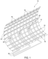
- An "inaccessible area" of a vehicle refers to an area of that vehicle that cannot be accessed during use of the vehicle because disassembly of some portion of the vehicle would be required to access such area. Referring now to FIG. 1 , an exemplary inaccessible area 12 is shown.
- area 12 is the area between the inner surface of a fuselage 10 of an aircraft and the sidewall (the sidewall itself is not shown in FIG. 1 , as one of ordinary skill will readily recognize, the sidewall is placed against the inner portion of fuselage 10 to create the inside environment of the aircraft).
- the system as defined in claim 1 and method of claim 13 may be used to remediate moisture from any inaccessible area of a commercial aircraft, and the area 12 between the fuselage 10 and the sidewall is only one example of an inaccessible area.
- the fuselage 10 consists of an outer skin 14 that is formed over frame members 18 and longitudinal stringers 16 in a conventional manner. A series of moisture sensors 20 are placed within the area 10 where moisture may accumulate.
- the moisture sensors 20 are preferably wireless and preferably output a signal corresponding to a current level of measure of moisture in an adjacent area upon receipt of an interrogation signal from a remote reader.
- Sensors 20 are preferably passive and receive power via the interrogation signal.
- sensors 20 may receive power via a wired connection and may output signals via wired connections.
- the wired connections may be integrated into the aircraft's electrical system (e.g., for power) or may be embedded in or attached to each on-board conduit 30 (discussed below) to run to the ground-based cart discussed herein.
- Sensors 20 may be passive devices which comprise a health monitoring sensor and one or more radio frequency identification (“RFID”) chips for communications.
- RFID radio frequency identification
- a corresponding on-board conduit 30 For each sensor 20 placed in an inaccessible area of a vehicle, a corresponding on-board conduit 30 is provided. In other examples, there may be more than one on-board conduit per sensor or, alternatively, more than one sensor per on-board conduit.
- Each on-board conduit 30 has a first end 25 positioned at an area near the corresponding sensor 20 and a second end 35 coupled to a manifold connector (not shown in FIG. 1 ).
- a manifold connector not shown in FIG. 1 .
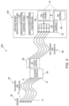
- a ground-based system 200 for detecting and removing moisture from inaccessible areas of the aircraft includes a plurality of sensors 20 and associated on-board conduits 30 located in inaccessible areas of the vehicle, as discussed with respect to FIG. 1 .
- Each of the on-board conduits 30 terminates at an on-board manifold connector 40 mounted on an accessible area on the vehicle.
- a dry gas supply unit 100 may be mounted on a cart and preferably includes a gas source 90, referred to and identified as an air source 90 in FIG. 2 , coupled to an air conditioner 80.
- Air conditioner 80 is coupled to an air distribution manifold 70. Air source 90 and air conditioner 80 combine to provide a source of dry gas 95.
- Air conditioner 80 selectively controls at least one of the pressure, volume, temperature, and humidity of the air output to air distribution manifold 70.
- Air source 90 may be a vent that inputs outside air to air conditioner 80.
- other air sources e.g., a tank of compressed dry air or of nitrogen, may be used to provide a dry compressed air or other gas source for use with the present system.
- air conditioner 80 may be omitted.
- Air distribution manifold 70 is coupled to an off-board manifold connector 50 via a plurality of off-board conduits 60 (each off-board conduit 60 is associated with a particular one of the on-board conduits 30). Air distribution manifold 70 is preferably controllable, so that the dry compressed air or gas may be selectively provided to either one or more or all of the off-board conduits 60 upon activation.
- each off-board conduit 60 is mated to the associated on-board conduit 30 so that dry compressed air or nitrogen pumped into a distal end of each off-board conduit 60 (i.e., the end terminating at air distribution manifold 70) passes through the two manifold connectors 40, 50 through the associated on-board conduit 30 and then to the area adjacent to the associated sensor 20.
- the dry gas supply unit 100 includes a control panel 120 and a controller 140.
- Control panel 120 is used to initiate the moisture detection and removal operation operations, to set the desired temperature, pressure and volume of the supplied air or gas, and to choose where the air or gas is directed (i.e., to select which of the conduits is supplied with air or gas).
- Controller 140 preferably interrogates each of the sensors 20 to determine whether moisture is present at areas adjacent to each sensor. The interrogation process may be done directly or via a connection to a handheld interrogation device (not shown) positioned within the vehicle. Alternatively, the handheld interrogation device may be used to interrogate each of the sensors 20 and a user may enter information identifying each of the sensors 20 outputting a moisture detection signal into control panel 120.
- Controller 140 also is coupled to the air distribution manifold 70 to, in a presently preferred example, selectively control the flow of dry compressed air or other gas into each of the conduits (e.g., via electronic control valves mounted on the manifold).
- the dry compressed air or other gas is only provided to off-board conduits 60 and the mating on-board conduits 30 that are associated with sensors 20 which signal that moisture is present in areas adjacent thereto.
- dry compressed air or other gas is provided to areas adjacent to all of the sensors 20 when any one of the sensors 20 indicate that moisture is present in the adjacent area (and no electronic control valves are required on manifold 70).
- Controller 140 also is preferably coupled to air conditioner 80 to specify one or more characteristics of the air to be provided to manifold 70, including but not limited to pressure, volume, temperature, and humidity.
- a lower pressure airflow may be provided to stimulate and enhance the evaporation process while a higher pressure airflow may be provided to direct standing water to nearby drains.
- controller 140 may be configured to operate in a sequence whereby, during a first period, a higher pressure airflow is imposed to move standing water to drains and, during a second period, a lower pressure airflow is imposed to stimulate and enhance the evaporation process of any remaining moisture.
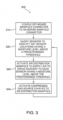
- a flowchart 300 for a ground-based method for detecting and removing moisture from inaccessible areas of the aircraft is provided.
- an off-board manifold connector 70 FIG. 2
- an on-board manifold connector 40 FIG. 2
- each of the sensors 20 is queried (interrogated) to determine which of the sensors 20, if any, sense moisture in an adjacent area above a predetermined threshold.
- the air distribution manifold 70 is activated so that dry compressed air or other gas, via associated on-board conduits 30, 60, is only provided to the areas adjacent to the sensors 20 identified in step 320.
- the dry compressed air or other gas source is coupled to air distribution manifold 70 to supply compress gas to the areas adjacent to the sensors 20 identified in step 320.
- the dry compressed air or other gas is on an intermittent basis during operation.
- the dry compressed air or other gas is supplied at a constant level. In either case, the dry compressed air or other gas may be first applied at a level strong enough to direct standing water to drains and then at a lower level to ensure that any remaining moisture is evaporated.
- processing may be completed or may iteratively return to step 320 until none of the sensors 20 sense moisture above the predetermined threshold.
- the system as defined in claim 1 and method of claim 13 provides the ability to flood certain areas of the aircraft such as a commercial aircraft with dry compressed air or gas preflight to reduce or eliminate condensation and frosting in those areas during flight.
- the system as defined in claim 1 and method of claim 13 also provides the ability to effectively melt and dry certain areas of the aircraft such as a commercial aircraft immediately post-flight to address condensation and frosting that may have occurred during flight.
- the system as defined in claim 1 can be installed as a retrofit in an existing aircraft such as a commercial aircraft by routing small diameter on-board air conduits each terminating at a first end in proximity to an associated one of a plurality of on-board moisture sensors and terminating at the second end at an on-board air conduit manifold that is connected to a ground-based cart while on the ground.
- the system and method disclosed herein may supplement other existing on-board moisture prevention and remediation systems. Further, the system and method disclosed herein can be used to address specific on-board moisture problems during gate turn-around and overnight service that are not readily addressed by conventional moisture
Landscapes
- Engineering & Computer Science (AREA)
- Aviation & Aerospace Engineering (AREA)
- Manufacturing & Machinery (AREA)
- Transportation (AREA)
- Mechanical Engineering (AREA)
- Investigating Or Analyzing Materials By The Use Of Electric Means (AREA)
Description
- The claimed invention relates generally to a system and method for detecting and removing moisture in an aircraft and, more particularly, for detecting and removing moisture within inaccessible areas of an aircraft to prevent corrosion from occurring in such inaccessible areas.
- The need to monitor the integrity of structural elements arises in many different applications. For example, it is necessary to monitor the structures of commercial aircraft. These aircraft stay in service for many years and may experience various working environments. Therefore, it is necessary to regularly check the structural integrity of the vehicle as part of any prudent maintenance program. Conventional testing techniques such as visual inspection, x-ray, dye penetrant, and electrical field techniques (e.g., eddy current testing, etc.) for testing structural elements have many drawbacks.
- Visual inspection of structural members often requires some degree of disassembly of the structure. This adds greatly to the overall testing cost. Commercial aircraft must be regularly inspected for structural integrity. However, visual inspection of aircraft structures often requires substantial disassembly of structure and removal of installed equipment in order to provide the access needed to view normally inaccessible areas of interest at a distance adequate to detect corrosion visually. For example, regular visual inspections to detect the presence of potential corrosion of metallic floor structure in wet areas of aircraft, such as behind sidewalls and under lavatories, galleys, and entry doors, can be burdensome. These time-consuming and costly inspections often reveal that the structure has no corrosion. Additionally, floor panel removal requires that factory seals be broken. Moreover, since there is a risk that the quality of the resealing may not be as high as the original factory seals, initial inspections may actually make the structure more susceptible to corrosion thereafter.
- Sensors have been used to detect the presence of moisture in the inaccessible areas of a commercial aircraft, but once detected it can still be time-consuming and costly to obtain access to such areas in order to remove the moisture and thereby prevent the buildup of corrosion.
- Accordingly, there is a need for a system and method which both identifies the presence of moisture in an inaccessible area of an aircraft and removes such moisture.
-
US 2010/087957 , in accordance with its abstract, states a system and methods for the storage, and preservation of mechanical assets, including collectable automobiles, small airplanes and watercraft in a storage unit. The storage unit includes a plurality of asset modules. The volume of each asset module is variable. The atmosphere of each asset module may be controlled by a control system. Control of the atmosphere of each asset module includes control of parameters including the type of gas each atmosphere is composed of and the temperature, the pressure and relative humidity of each atmosphere. These parameters may be monitored and controlled from a remote location. -
WO 2006/012266 , in accordance with its abstract, states a mobile platform comprising at least one mobile platform system that includes a processor, a structure, and an SHM system. The SHM system also includes a processor as well as a structural sensor. The SHM processor is separate from the mobile platform system processor. The mobile platform includes a flight control system, a maintenance information system, and an IVHM system. The SHM system may receive parameters from the flight control system and calculate loads therefrom. Alternatively, the sensor may be a structural load sensor, which the SHM processor uses along with the parameters, to calculate other structural loads. A method is provided that includes separating SHM functions from a processor of a mobile platform system. The method also includes dedicating an SHM system to perform SHM functions and establishing communications between the SHM system and the mobile platform system. -
US 9546004 -
US 2008/283663 , in accordance with its abstract, states systems and methods for providing airflow in an aerospace vehicle. A system in accordance with one embodiment includes an aerospace vehicle having an interior volume with a first portion and a second portion. The system can further include an external air supply device positioned to provide supply air to the interior volume at a variable supply flow rate and a recirculation fan configured to move air positioned within the interior volume between the first portion of the interior volume and the second portion of the interior volume. The system can still further include a controller operably coupled to the recirculation fan and configured to vary a rotation speed of the recirculation fan. Variations in the rotation speed of the recirculation fan can be associated with variations in a recirculation flow rate. In selected embodiments, the system can include sensors and/or data link devices operably coupled to the controller. - In a first aspect of the claimed invention, a ground-based system for detecting and removing moisture in inaccessible areas of an aircraft is described in accordance with claim 1.
- Each moisture detection sensor may be mounted in an area that is inaccessible during flight of the aircraft. Still further, each moisture detection sensor may be passive and output a signal upon receipt of an external interrogation signal. In addition, the external interrogation signal may originate at a controller that is part of the dry gas supply unit or may originate at a hand-held controller.
- Still further, the dry gas supply unit may include a source of dry gas, a manifold having a first end coupled to the source of dry gas and a second end coupled to the second ends of each of the at least one on-board conduits, and a controller that is coupled to the manifold for selectively enabling the manifold to provide dry gas only to the second ends of those of the at least one on-board conduits having an associated sensor outputting a signal indicating that moisture is present in the area adjacent thereto. The source of dry gas may be an air conditioner coupled to a gas source. The air conditioner may control at least one of pressure, volume, temperature, and humidity of the dry gas provided to the manifold. The source of dry gas may be a tank of nitrogen.
- In a second aspect of the claimed invention, a method for detecting and removing moisture in inaccessible areas of an aircraft is described in accordance with claim 13.
- Further, dry gas may be provided only to the second ends of on-board conduits having a first end mounted adjacent to a moisture detection sensor having moisture present in the area adjacent thereto.
- The features, functions, and advantages that have been discussed can be achieved independently in various examples or may be combined in yet other examples, further details of which can be seen with reference to the following description and drawings.
- The following detailed description, given by way of example and not intended to limit claimed invention solely thereto, will best be understood in conjunction with the accompanying drawings in which:
-
FIG. 1 is a diagram showing an aircraft fuselage portion including a series of sensors and associated conduits installed therein; -
FIG. 2 is a block diagram of a system for detecting and removing moisture in an aircraft as defined in claim 1; and -
FIG. 3 is a flowchart of a method for detecting and removing moisture in an aircraft as defined in claim 13, representing an embodiment of the claimed invention. - Like reference numbers refer to like elements throughout the drawings.
- It is provided a ground-based system and method for detecting and removing moisture from inaccessible areas of a vehicle such as a commercial aircraft. As discussed above, such inaccessible areas in an aircraft may include, for example, areas behind sidewalls and under lavatories, galleys, and entry doors. As one of ordinary skill in the art will readily recognize, there can be many other inaccessible areas in which moisture may collect during operation of an aircraft. An "inaccessible area" of a vehicle refers to an area of that vehicle that cannot be accessed during use of the vehicle because disassembly of some portion of the vehicle would be required to access such area. Referring now to
FIG. 1 , an exemplary inaccessible area 12 is shown. In particular, area 12 is the area between the inner surface of afuselage 10 of an aircraft and the sidewall (the sidewall itself is not shown inFIG. 1 , as one of ordinary skill will readily recognize, the sidewall is placed against the inner portion offuselage 10 to create the inside environment of the aircraft). The system as defined in claim 1 and method of claim 13 may be used to remediate moisture from any inaccessible area of a commercial aircraft, and the area 12 between thefuselage 10 and the sidewall is only one example of an inaccessible area. Thefuselage 10 consists of anouter skin 14 that is formed overframe members 18 andlongitudinal stringers 16 in a conventional manner. A series ofmoisture sensors 20 are placed within thearea 10 where moisture may accumulate. Themoisture sensors 20 are preferably wireless and preferably output a signal corresponding to a current level of measure of moisture in an adjacent area upon receipt of an interrogation signal from a remote reader.Sensors 20 are preferably passive and receive power via the interrogation signal. However, in other examples,sensors 20 may receive power via a wired connection and may output signals via wired connections. The wired connections may be integrated into the aircraft's electrical system (e.g., for power) or may be embedded in or attached to each on-board conduit 30 (discussed below) to run to the ground-based cart discussed herein.Sensors 20 may be passive devices which comprise a health monitoring sensor and one or more radio frequency identification ("RFID") chips for communications. For eachsensor 20 placed in an inaccessible area of a vehicle, a corresponding on-board conduit 30 is provided. In other examples, there may be more than one on-board conduit per sensor or, alternatively, more than one sensor per on-board conduit. Each on-board conduit 30 has afirst end 25 positioned at an area near the correspondingsensor 20 and asecond end 35 coupled to a manifold connector (not shown inFIG. 1 ). As discussed below, during the moisture detection and removal process, when asensor 20 indicates the presence of moisture, dry compressed air or nitrogen gas is pumped, e.g., intermittently, into the associated on-board conduit 30 (via a ground-based cart discussed with respect toFIG. 2 ) to flood the area around thatsensor 20 with dry compressed air or nitrogen gas in order to remove the moisture from such area by directing standing water to drains and to evaporate any remaining moisture. By using fractional inch tubing for the on-board conduits 30 and self-adhesive RFID-based sensors forsensors 20, an extremely lightweight solution for an installed moisture removal system installed in a commercial aircraft is provided. In addition, the use of RFID-based sensors ensures that the system may be completely passive with respect to the aircraft's electronic system, no on-board power is required in the preferred example at all. - Referring now to
FIG. 2 , a ground-basedsystem 200 for detecting and removing moisture from inaccessible areas of the aircraft includes a plurality ofsensors 20 and associated on-board conduits 30 located in inaccessible areas of the vehicle, as discussed with respect toFIG. 1 . Each of the on-board conduits 30 terminates at an on-board manifold connector 40 mounted on an accessible area on the vehicle. A drygas supply unit 100 may be mounted on a cart and preferably includes agas source 90, referred to and identified as anair source 90 inFIG. 2 , coupled to anair conditioner 80.Air conditioner 80, in turn, is coupled to anair distribution manifold 70. Airsource 90 andair conditioner 80 combine to provide a source ofdry gas 95. Other sources ofdry gas 95 can use alternate gases, such as but not limited to nitrogen, to provide the dry gas needed to remove moisture accumulated near any one of thesensors 20.Air conditioner 80 selectively controls at least one of the pressure, volume, temperature, and humidity of the air output toair distribution manifold 70. Airsource 90 may be a vent that inputs outside air toair conditioner 80. In the alternative, other air sources, e.g., a tank of compressed dry air or of nitrogen, may be used to provide a dry compressed air or other gas source for use with the present system. In some cases, e.g., when a tank of nitrogen gas is used,air conditioner 80 may be omitted.Air distribution manifold 70 is coupled to an off-board manifold connector 50 via a plurality of off-board conduits 60 (each off-board conduit 60 is associated with a particular one of the on-board conduits 30).Air distribution manifold 70 is preferably controllable, so that the dry compressed air or gas may be selectively provided to either one or more or all of the off-board conduits 60 upon activation. When off-board manifold connector 50 is mated to on-board manifold connector 40, each off-board conduit 60 is mated to the associated on-board conduit 30 so that dry compressed air or nitrogen pumped into a distal end of each off-board conduit 60 (i.e., the end terminating at air distribution manifold 70) passes through the twomanifold connectors board conduit 30 and then to the area adjacent to the associatedsensor 20. - The dry
gas supply unit 100 includes acontrol panel 120 and acontroller 140.Control panel 120 is used to initiate the moisture detection and removal operation operations, to set the desired temperature, pressure and volume of the supplied air or gas, and to choose where the air or gas is directed (i.e., to select which of the conduits is supplied with air or gas).Controller 140 preferably interrogates each of thesensors 20 to determine whether moisture is present at areas adjacent to each sensor. The interrogation process may be done directly or via a connection to a handheld interrogation device (not shown) positioned within the vehicle. Alternatively, the handheld interrogation device may be used to interrogate each of thesensors 20 and a user may enter information identifying each of thesensors 20 outputting a moisture detection signal intocontrol panel 120.Controller 140 also is coupled to theair distribution manifold 70 to, in a presently preferred example, selectively control the flow of dry compressed air or other gas into each of the conduits (e.g., via electronic control valves mounted on the manifold). Preferably, the dry compressed air or other gas is only provided to off-board conduits 60 and the mating on-board conduits 30 that are associated withsensors 20 which signal that moisture is present in areas adjacent thereto. However, in an alternative example, dry compressed air or other gas is provided to areas adjacent to all of thesensors 20 when any one of thesensors 20 indicate that moisture is present in the adjacent area (and no electronic control valves are required on manifold 70).Controller 140 also is preferably coupled toair conditioner 80 to specify one or more characteristics of the air to be provided tomanifold 70, including but not limited to pressure, volume, temperature, and humidity. Notably, a lower pressure airflow may be provided to stimulate and enhance the evaporation process while a higher pressure airflow may be provided to direct standing water to nearby drains. In that respect,controller 140 may be configured to operate in a sequence whereby, during a first period, a higher pressure airflow is imposed to move standing water to drains and, during a second period, a lower pressure airflow is imposed to stimulate and enhance the evaporation process of any remaining moisture. - Referring now to
FIG. 3 , aflowchart 300 for a ground-based method for detecting and removing moisture from inaccessible areas of the aircraft is provided. In afirst step 310, an off-board manifold connector 70 (FIG. 2 ) is coupled to an on-board manifold connector 40. Next, atstep 320, each of thesensors 20 is queried (interrogated) to determine which of thesensors 20, if any, sense moisture in an adjacent area above a predetermined threshold. Once thesensors 20 identifying areas with moisture are identified, theair distribution manifold 70 is activated so that dry compressed air or other gas, via associated on-board conduits sensors 20 identified instep 320. Finally, atstep 340, the dry compressed air or other gas source is coupled toair distribution manifold 70 to supply compress gas to the areas adjacent to thesensors 20 identified instep 320. In one example, the dry compressed air or other gas is on an intermittent basis during operation. In another example, the dry compressed air or other gas is supplied at a constant level. In either case, the dry compressed air or other gas may be first applied at a level strong enough to direct standing water to drains and then at a lower level to ensure that any remaining moisture is evaporated. Afterstep 340 is completed, processing may be completed or may iteratively return to step 320 until none of thesensors 20 sense moisture above the predetermined threshold. - The system as defined in claim 1 and method of claim 13 provides the ability to flood certain areas of the aircraft such as a commercial aircraft with dry compressed air or gas preflight to reduce or eliminate condensation and frosting in those areas during flight. The system as defined in claim 1 and method of claim 13 also provides the ability to effectively melt and dry certain areas of the aircraft such as a commercial aircraft immediately post-flight to address condensation and frosting that may have occurred during flight. The system as defined in claim 1 can be installed as a retrofit in an existing aircraft such as a commercial aircraft by routing small diameter on-board air conduits each terminating at a first end in proximity to an associated one of a plurality of on-board moisture sensors and terminating at the second end at an on-board air conduit manifold that is connected to a ground-based cart while on the ground. The system and method disclosed herein may supplement other existing on-board moisture prevention and remediation systems. Further, the system and method disclosed herein can be used to address specific on-board moisture problems during gate turn-around and overnight service that are not readily addressed by conventional moisture prevention and remediation systems.
Claims (15)
- A ground-based system (200) for detecting and removing moisture from inaccessible areas of an aircraft, the system (200) comprising:
the aircraft comprising:at least one moisture detection sensor (20) mounted in the inaccessible areas of the aircraft for outputting a signal when moisture level is above a predetermined threshold in an area adjacent thereto; andat least one on-board conduit (30) installed in the inaccessible areas of the aircraft having a first end (25) adjacent to an associated one of the at least one moisture detection sensor (20) and a second end (35); and wherein the system (200) further comprises:
a dry gas supply unit (100) separate from the aircraft that is adapted to be coupled to the second end (35) of each of the at least one on-board conduit (30) of the aircraft to selectively supply dry gas thereto, the dry gas supply unit (100) configured to selectively supply dry gas to the second end (35) of each of the at least one on-board conduits (30) when the at least one moisture detection sensor (20) associated with a particular on-board conduit (30) outputs a signal indicating that moisture level is above the predetermined threshold in the area adjacent thereto. - The system (200) of claim 1, wherein each moisture detection sensor (20) is each mounted in the area that is inaccessible during flight of the aircraft.
- The system (200) of claim 2, wherein the inaccessible area of the aircraft is located between a sidewall forming an inside environment of the aircraft, and an inner surface of a fuselage (10) of the aircraft.
- The system (200) of any one of claims 1-3, wherein each moisture detection sensor (20) is passive and outputs a signal upon receipt of an external interrogation signal.
- The system (200) of any one of claims 1-4, wherein each moisture detection sensor (20) is a wireless sensor.
- The system (200) of claim 4, wherein the external interrogation signal originates at a controller (140) that is part of the dry gas supply unit (100).
- The system (200) of claim 4, wherein the external interrogation signal originates at a hand-held controller.
- The system (200) of any one of claims 1-7, wherein the dry gas supply unit (100) comprises:a source of dry gas (95);an air distribution manifold (70) coupled to the source of dry gas (95) and the second ends (35) of each on-board conduit (30); anda controller (140) coupled to the air distribution manifold (70), the controller (140) is configured for selectively enabling the air distribution manifold (70) to provide dry gas only to the second ends (35) of those of the at least one on-board conduits (30) having an associated sensor (20) outputting a signal indicating that moisture level is above the predetermined threshold in the area adjacent thereto.
- The system (200) of claim 8, wherein the controller (140) is configured to selectively control the airflow, such that:during a first period a higher pressure airflow is imposed to move standing water to drains and,during a second period, a lower pressure airflow is imposed to stimulate and enhance the evaporation process of any remaining moisture.
- The system (200) of any one of claims 8-9, wherein the source of dry gas (95) comprises an air conditioner (80) coupled to a gas source (90).
- The system (200) of claim 10, wherein the air conditioner (80) is configured to control at least one of pressure, volume, temperature, and humidity of the dry gas provided to the air distribution manifold (70).
- The system (200) of claim 8, wherein the source of dry gas (95) is a tank of nitrogen.
- A method (300) for detecting and removing moisture in inaccessible areas of an aircraft, the aircraft including a plurality of moisture detection sensors (20) mounted in the inaccessible areas of the aircraft and a plurality of on-board conduits (30) installed in the inaccessible areas and having respectively a first end (25) positioned adjacent to the respective moisture detection sensor (20) and a second end (35), comprising the steps of:coupling (step 310) a dry gas supply unit (100) not present on the aircraft to the second end (35) of each of the plurality of on-board conduits (30) via an air distribution manifold (70) that is controllable, said air distribution manifold (70) being part of the dry gas supply unit (100);interrogating (step 320) each of the moisture detection sensors (20) to determine if moisture level is above a predetermined threshold in an area adjacent thereto; andwhen at least one of the moisture detection sensors (20) indicates that moisture level is above the predetermined threshold in the area adjacent thereto, activating (step 330) the air distribution manifold (70) of the dry gas supply unit (100) so that dry gas is provided to the second ends (35) of the plurality of on-board conduits (30).
- The method (300) of claim 13, wherein dry gas is provided only to the second ends (35) of the plurality of on-board conduits (30) having the first end (25) mounted adjacent to the moisture detection sensor (20) having moisture level above the predetermined threshold in the area adjacent thereto.
- The method (300) of any one of claims 13-14, wherein the dry gas is nitrogen.
Applications Claiming Priority (1)
| Application Number | Priority Date | Filing Date | Title |
|---|---|---|---|
| US15/446,661 US10293958B2 (en) | 2017-03-01 | 2017-03-01 | System and method for detecting and removing moisture in an aircraft |
Publications (2)
| Publication Number | Publication Date |
|---|---|
| EP3369661A1 EP3369661A1 (en) | 2018-09-05 |
| EP3369661B1 true EP3369661B1 (en) | 2023-11-15 |
Family
ID=61274089
Family Applications (1)
| Application Number | Title | Priority Date | Filing Date |
|---|---|---|---|
| EP18158096.0A Active EP3369661B1 (en) | 2017-03-01 | 2018-02-22 | System and method for detecting and removing moisture in an aircraft |
Country Status (4)
| Country | Link |
|---|---|
| US (1) | US10293958B2 (en) |
| EP (1) | EP3369661B1 (en) |
| BR (1) | BR102018004071B1 (en) |
| CA (1) | CA2996567C (en) |
Families Citing this family (7)
| Publication number | Priority date | Publication date | Assignee | Title |
|---|---|---|---|---|
| US10422742B2 (en) * | 2017-10-18 | 2019-09-24 | The Boeing Company | Moisture detection system |
| US10656081B2 (en) | 2017-10-18 | 2020-05-19 | The Boeing Company | Synchronized phased array and infrared detector system for moisture detection |
| US11220357B2 (en) * | 2019-01-18 | 2022-01-11 | The Boeing Company | Aircraft maintenance systems and methods |
| US11858641B2 (en) * | 2019-10-24 | 2024-01-02 | The Boeing Company | Aircraft moisture control |
| US11518522B2 (en) | 2019-10-24 | 2022-12-06 | The Boeing Company | Aircraft moisture control |
| US12330815B2 (en) * | 2020-06-09 | 2025-06-17 | Ami Industries, Inc. | Method and apparatus for disinfecting a vehicle interior |
| CN114180089B (en) * | 2021-12-11 | 2024-02-02 | 浙江极客桥智能装备股份有限公司 | Unmanned aerial vehicle air park system |
Citations (2)
| Publication number | Priority date | Publication date | Assignee | Title |
|---|---|---|---|---|
| US20080283663A1 (en) * | 2007-05-17 | 2008-11-20 | The Boeing Company | Systems and methods for providing airflow in an aerospace vehicle |
| US9546004B1 (en) * | 2014-03-17 | 2017-01-17 | The Boeing Company | Water and ice detection and quantitative assessment system for ingression prone areas in an aircraft |
Family Cites Families (9)
| Publication number | Priority date | Publication date | Assignee | Title |
|---|---|---|---|---|
| US4272014A (en) * | 1978-12-26 | 1981-06-09 | Lockheed Corporation | Humidification system |
| US7175136B2 (en) * | 2003-04-16 | 2007-02-13 | The Boeing Company | Method and apparatus for detecting conditions conducive to ice formation |
| US20060004499A1 (en) | 2004-06-30 | 2006-01-05 | Angela Trego | Structural health management architecture using sensor technology |
| EP1894074A4 (en) * | 2005-06-13 | 2010-05-19 | Sigma Systems Corp | Methods and apparatus for optimizing environmental humidity |
| JP4523884B2 (en) * | 2005-06-30 | 2010-08-11 | 株式会社東芝 | Image forming apparatus and image forming apparatus management method |
| US8040243B2 (en) * | 2008-11-18 | 2011-10-18 | The Boeing Company | RFID-based corrosion and moisture detection |
| US7967250B2 (en) | 2008-05-12 | 2011-06-28 | EMBRAER—Empresa Brasileira de Aeronáutica | Hybrid aircraft fuselage structural components and methods of making same |
| EP2350762A4 (en) | 2008-10-08 | 2016-04-20 | Michael P Gibbons | SYSTEM AND METHODS FOR THE PRESERVATION OF MECHANICAL GOODS |
| US9102392B2 (en) | 2010-12-15 | 2015-08-11 | The Boeing Company | Method and apparatus for air flow control in an aircraft sidewall volume |
-
2017
- 2017-03-01 US US15/446,661 patent/US10293958B2/en active Active
-
2018
- 2018-02-22 EP EP18158096.0A patent/EP3369661B1/en active Active
- 2018-02-26 CA CA2996567A patent/CA2996567C/en active Active
- 2018-02-28 BR BR102018004071-5A patent/BR102018004071B1/en active IP Right Grant
Patent Citations (2)
| Publication number | Priority date | Publication date | Assignee | Title |
|---|---|---|---|---|
| US20080283663A1 (en) * | 2007-05-17 | 2008-11-20 | The Boeing Company | Systems and methods for providing airflow in an aerospace vehicle |
| US9546004B1 (en) * | 2014-03-17 | 2017-01-17 | The Boeing Company | Water and ice detection and quantitative assessment system for ingression prone areas in an aircraft |
Also Published As
| Publication number | Publication date |
|---|---|
| CA2996567C (en) | 2022-07-26 |
| BR102018004071B1 (en) | 2023-12-26 |
| BR102018004071A2 (en) | 2018-12-18 |
| US20180251235A1 (en) | 2018-09-06 |
| US10293958B2 (en) | 2019-05-21 |
| CA2996567A1 (en) | 2018-09-01 |
| EP3369661A1 (en) | 2018-09-05 |
Similar Documents
| Publication | Publication Date | Title |
|---|---|---|
| CA2996567C (en) | System and method for detecting and removing moisture in an aircraft | |
| US11488421B2 (en) | Sensor signal processing system and method | |
| US8355830B2 (en) | Aircraft health monitoring and design for condition | |
| CN109477771B (en) | Structural health monitoring system for identifying damage through device based on augmented reality technology | |
| JP6479357B2 (en) | Wireless fuel sensor system and method | |
| CN102132137B (en) | Fluid detection with a spectrometer-on-a-chip | |
| US8237548B2 (en) | Structural health management device and associated system and method | |
| US20190161103A1 (en) | System, Method, and Computer Program Product for Automatic Inspection of a Train | |
| KR20200018454A (en) | Modular vehicles with two-stage insulation corrosion detection methodology and two-movement sensor system | |
| JP2020027095A (en) | Conveying system inspection device (doctor logistics) | |
| EP3689743B1 (en) | Augmented weight sensing for aircraft cargo handling systems | |
| KR102192686B1 (en) | Drone controlling system for checking of facility, and method for the same | |
| US20170269592A1 (en) | Use of Unmanned Aerial Vehicles for NDT Inspections | |
| CN109697810A (en) | For monitoring the system for entering the vehicles | |
| US9574963B2 (en) | Device for monitoring a probe for measuring the pressure of a flow | |
| CN110702268B (en) | Cable temperature monitoring method and system applied to rail transit | |
| EP3259210B1 (en) | Apparatus and method for monitoring cargo conditions | |
| CN107415983A (en) | The vehicle-mounted bearing temperature on-Line Monitor Device of the quick lorry of railway | |
| US20250383125A1 (en) | Heating system and method for an aircraft water circuit | |
| CN106205115A (en) | A kind of oil truck safety monitoring system | |
| KR20140070051A (en) | Risk Analysis railway vehicle on-board systems of the main unit | |
| Norris | Boeing, FedEx test active radio tags | |
| CN106210628A (en) | power equipment monitoring system |
Legal Events
| Date | Code | Title | Description |
|---|---|---|---|
| PUAI | Public reference made under article 153(3) epc to a published international application that has entered the european phase |
Free format text: ORIGINAL CODE: 0009012 |
|
| STAA | Information on the status of an ep patent application or granted ep patent |
Free format text: STATUS: REQUEST FOR EXAMINATION WAS MADE |
|
| 17P | Request for examination filed |
Effective date: 20180222 |
|
| AK | Designated contracting states |
Kind code of ref document: A1 Designated state(s): AL AT BE BG CH CY CZ DE DK EE ES FI FR GB GR HR HU IE IS IT LI LT LU LV MC MK MT NL NO PL PT RO RS SE SI SK SM TR |
|
| AX | Request for extension of the european patent |
Extension state: BA ME |
|
| RBV | Designated contracting states (corrected) |
Designated state(s): AL AT BE BG CH CY CZ DE DK EE ES FI FR GB GR HR HU IE IS IT LI LT LU LV MC MK MT NL NO PL PT RO RS SE SI SK SM TR |
|
| R17P | Request for examination filed (corrected) |
Effective date: 20180222 |
|
| STAA | Information on the status of an ep patent application or granted ep patent |
Free format text: STATUS: EXAMINATION IS IN PROGRESS |
|
| 17Q | First examination report despatched |
Effective date: 20210818 |
|
| RAP3 | Party data changed (applicant data changed or rights of an application transferred) |
Owner name: THE BOEING COMPANY |
|
| GRAP | Despatch of communication of intention to grant a patent |
Free format text: ORIGINAL CODE: EPIDOSNIGR1 |
|
| STAA | Information on the status of an ep patent application or granted ep patent |
Free format text: STATUS: GRANT OF PATENT IS INTENDED |
|
| INTG | Intention to grant announced |
Effective date: 20230713 |
|
| GRAS | Grant fee paid |
Free format text: ORIGINAL CODE: EPIDOSNIGR3 |
|
| GRAA | (expected) grant |
Free format text: ORIGINAL CODE: 0009210 |
|
| STAA | Information on the status of an ep patent application or granted ep patent |
Free format text: STATUS: THE PATENT HAS BEEN GRANTED |
|
| AK | Designated contracting states |
Kind code of ref document: B1 Designated state(s): AL AT BE BG CH CY CZ DE DK EE ES FI FR GB GR HR HU IE IS IT LI LT LU LV MC MK MT NL NO PL PT RO RS SE SI SK SM TR |
|
| P01 | Opt-out of the competence of the unified patent court (upc) registered |
Effective date: 20231006 |
|
| REG | Reference to a national code |
Ref country code: CH Ref legal event code: EP Ref country code: GB Ref legal event code: FG4D |
|
| P02 | Opt-out of the competence of the unified patent court (upc) changed |
Effective date: 20231006 |
|
| REG | Reference to a national code |
Ref country code: DE Ref legal event code: R096 Ref document number: 602018061039 Country of ref document: DE |
|
| REG | Reference to a national code |
Ref country code: IE Ref legal event code: FG4D |
|
| REG | Reference to a national code |
Ref country code: LT Ref legal event code: MG9D |
|
| REG | Reference to a national code |
Ref country code: NL Ref legal event code: MP Effective date: 20231115 |
|
| PG25 | Lapsed in a contracting state [announced via postgrant information from national office to epo] |
Ref country code: GR Free format text: LAPSE BECAUSE OF FAILURE TO SUBMIT A TRANSLATION OF THE DESCRIPTION OR TO PAY THE FEE WITHIN THE PRESCRIBED TIME-LIMIT Effective date: 20240216 |
|
| PG25 | Lapsed in a contracting state [announced via postgrant information from national office to epo] |
Ref country code: IS Free format text: LAPSE BECAUSE OF FAILURE TO SUBMIT A TRANSLATION OF THE DESCRIPTION OR TO PAY THE FEE WITHIN THE PRESCRIBED TIME-LIMIT Effective date: 20240315 |
|
| PG25 | Lapsed in a contracting state [announced via postgrant information from national office to epo] |
Ref country code: LT Free format text: LAPSE BECAUSE OF FAILURE TO SUBMIT A TRANSLATION OF THE DESCRIPTION OR TO PAY THE FEE WITHIN THE PRESCRIBED TIME-LIMIT Effective date: 20231115 |
|
| REG | Reference to a national code |
Ref country code: AT Ref legal event code: MK05 Ref document number: 1631558 Country of ref document: AT Kind code of ref document: T Effective date: 20231115 |
|
| PG25 | Lapsed in a contracting state [announced via postgrant information from national office to epo] |
Ref country code: NL Free format text: LAPSE BECAUSE OF FAILURE TO SUBMIT A TRANSLATION OF THE DESCRIPTION OR TO PAY THE FEE WITHIN THE PRESCRIBED TIME-LIMIT Effective date: 20231115 |
|
| PG25 | Lapsed in a contracting state [announced via postgrant information from national office to epo] |
Ref country code: AT Free format text: LAPSE BECAUSE OF FAILURE TO SUBMIT A TRANSLATION OF THE DESCRIPTION OR TO PAY THE FEE WITHIN THE PRESCRIBED TIME-LIMIT Effective date: 20231115 |
|
| PG25 | Lapsed in a contracting state [announced via postgrant information from national office to epo] |
Ref country code: ES Free format text: LAPSE BECAUSE OF FAILURE TO SUBMIT A TRANSLATION OF THE DESCRIPTION OR TO PAY THE FEE WITHIN THE PRESCRIBED TIME-LIMIT Effective date: 20231115 |
|
| PG25 | Lapsed in a contracting state [announced via postgrant information from national office to epo] |
Ref country code: NL Free format text: LAPSE BECAUSE OF FAILURE TO SUBMIT A TRANSLATION OF THE DESCRIPTION OR TO PAY THE FEE WITHIN THE PRESCRIBED TIME-LIMIT Effective date: 20231115 Ref country code: LT Free format text: LAPSE BECAUSE OF FAILURE TO SUBMIT A TRANSLATION OF THE DESCRIPTION OR TO PAY THE FEE WITHIN THE PRESCRIBED TIME-LIMIT Effective date: 20231115 Ref country code: IS Free format text: LAPSE BECAUSE OF FAILURE TO SUBMIT A TRANSLATION OF THE DESCRIPTION OR TO PAY THE FEE WITHIN THE PRESCRIBED TIME-LIMIT Effective date: 20240315 Ref country code: GR Free format text: LAPSE BECAUSE OF FAILURE TO SUBMIT A TRANSLATION OF THE DESCRIPTION OR TO PAY THE FEE WITHIN THE PRESCRIBED TIME-LIMIT Effective date: 20240216 Ref country code: ES Free format text: LAPSE BECAUSE OF FAILURE TO SUBMIT A TRANSLATION OF THE DESCRIPTION OR TO PAY THE FEE WITHIN THE PRESCRIBED TIME-LIMIT Effective date: 20231115 Ref country code: BG Free format text: LAPSE BECAUSE OF FAILURE TO SUBMIT A TRANSLATION OF THE DESCRIPTION OR TO PAY THE FEE WITHIN THE PRESCRIBED TIME-LIMIT Effective date: 20240215 Ref country code: AT Free format text: LAPSE BECAUSE OF FAILURE TO SUBMIT A TRANSLATION OF THE DESCRIPTION OR TO PAY THE FEE WITHIN THE PRESCRIBED TIME-LIMIT Effective date: 20231115 Ref country code: PT Free format text: LAPSE BECAUSE OF FAILURE TO SUBMIT A TRANSLATION OF THE DESCRIPTION OR TO PAY THE FEE WITHIN THE PRESCRIBED TIME-LIMIT Effective date: 20240315 |
|
| PG25 | Lapsed in a contracting state [announced via postgrant information from national office to epo] |
Ref country code: SE Free format text: LAPSE BECAUSE OF FAILURE TO SUBMIT A TRANSLATION OF THE DESCRIPTION OR TO PAY THE FEE WITHIN THE PRESCRIBED TIME-LIMIT Effective date: 20231115 Ref country code: RS Free format text: LAPSE BECAUSE OF FAILURE TO SUBMIT A TRANSLATION OF THE DESCRIPTION OR TO PAY THE FEE WITHIN THE PRESCRIBED TIME-LIMIT Effective date: 20231115 Ref country code: PL Free format text: LAPSE BECAUSE OF FAILURE TO SUBMIT A TRANSLATION OF THE DESCRIPTION OR TO PAY THE FEE WITHIN THE PRESCRIBED TIME-LIMIT Effective date: 20231115 Ref country code: NO Free format text: LAPSE BECAUSE OF FAILURE TO SUBMIT A TRANSLATION OF THE DESCRIPTION OR TO PAY THE FEE WITHIN THE PRESCRIBED TIME-LIMIT Effective date: 20240215 Ref country code: LV Free format text: LAPSE BECAUSE OF FAILURE TO SUBMIT A TRANSLATION OF THE DESCRIPTION OR TO PAY THE FEE WITHIN THE PRESCRIBED TIME-LIMIT Effective date: 20231115 Ref country code: HR Free format text: LAPSE BECAUSE OF FAILURE TO SUBMIT A TRANSLATION OF THE DESCRIPTION OR TO PAY THE FEE WITHIN THE PRESCRIBED TIME-LIMIT Effective date: 20231115 |
|
| PG25 | Lapsed in a contracting state [announced via postgrant information from national office to epo] |
Ref country code: DK Free format text: LAPSE BECAUSE OF FAILURE TO SUBMIT A TRANSLATION OF THE DESCRIPTION OR TO PAY THE FEE WITHIN THE PRESCRIBED TIME-LIMIT Effective date: 20231115 |
|
| PG25 | Lapsed in a contracting state [announced via postgrant information from national office to epo] |
Ref country code: CZ Free format text: LAPSE BECAUSE OF FAILURE TO SUBMIT A TRANSLATION OF THE DESCRIPTION OR TO PAY THE FEE WITHIN THE PRESCRIBED TIME-LIMIT Effective date: 20231115 |
|
| PG25 | Lapsed in a contracting state [announced via postgrant information from national office to epo] |
Ref country code: SK Free format text: LAPSE BECAUSE OF FAILURE TO SUBMIT A TRANSLATION OF THE DESCRIPTION OR TO PAY THE FEE WITHIN THE PRESCRIBED TIME-LIMIT Effective date: 20231115 |
|
| PG25 | Lapsed in a contracting state [announced via postgrant information from national office to epo] |
Ref country code: SM Free format text: LAPSE BECAUSE OF FAILURE TO SUBMIT A TRANSLATION OF THE DESCRIPTION OR TO PAY THE FEE WITHIN THE PRESCRIBED TIME-LIMIT Effective date: 20231115 Ref country code: SK Free format text: LAPSE BECAUSE OF FAILURE TO SUBMIT A TRANSLATION OF THE DESCRIPTION OR TO PAY THE FEE WITHIN THE PRESCRIBED TIME-LIMIT Effective date: 20231115 Ref country code: RO Free format text: LAPSE BECAUSE OF FAILURE TO SUBMIT A TRANSLATION OF THE DESCRIPTION OR TO PAY THE FEE WITHIN THE PRESCRIBED TIME-LIMIT Effective date: 20231115 Ref country code: IT Free format text: LAPSE BECAUSE OF FAILURE TO SUBMIT A TRANSLATION OF THE DESCRIPTION OR TO PAY THE FEE WITHIN THE PRESCRIBED TIME-LIMIT Effective date: 20231115 Ref country code: EE Free format text: LAPSE BECAUSE OF FAILURE TO SUBMIT A TRANSLATION OF THE DESCRIPTION OR TO PAY THE FEE WITHIN THE PRESCRIBED TIME-LIMIT Effective date: 20231115 Ref country code: DK Free format text: LAPSE BECAUSE OF FAILURE TO SUBMIT A TRANSLATION OF THE DESCRIPTION OR TO PAY THE FEE WITHIN THE PRESCRIBED TIME-LIMIT Effective date: 20231115 Ref country code: CZ Free format text: LAPSE BECAUSE OF FAILURE TO SUBMIT A TRANSLATION OF THE DESCRIPTION OR TO PAY THE FEE WITHIN THE PRESCRIBED TIME-LIMIT Effective date: 20231115 |
|
| REG | Reference to a national code |
Ref country code: DE Ref legal event code: R097 Ref document number: 602018061039 Country of ref document: DE |
|
| PLBE | No opposition filed within time limit |
Free format text: ORIGINAL CODE: 0009261 |
|
| STAA | Information on the status of an ep patent application or granted ep patent |
Free format text: STATUS: NO OPPOSITION FILED WITHIN TIME LIMIT |
|
| PG25 | Lapsed in a contracting state [announced via postgrant information from national office to epo] |
Ref country code: MC Free format text: LAPSE BECAUSE OF FAILURE TO SUBMIT A TRANSLATION OF THE DESCRIPTION OR TO PAY THE FEE WITHIN THE PRESCRIBED TIME-LIMIT Effective date: 20231115 |
|
| REG | Reference to a national code |
Ref country code: CH Ref legal event code: PL |
|
| PG25 | Lapsed in a contracting state [announced via postgrant information from national office to epo] |
Ref country code: LU Free format text: LAPSE BECAUSE OF NON-PAYMENT OF DUE FEES Effective date: 20240222 |
|
| PG25 | Lapsed in a contracting state [announced via postgrant information from national office to epo] |
Ref country code: CH Free format text: LAPSE BECAUSE OF NON-PAYMENT OF DUE FEES Effective date: 20240229 |
|
| 26N | No opposition filed |
Effective date: 20240819 |
|
| PG25 | Lapsed in a contracting state [announced via postgrant information from national office to epo] |
Ref country code: SI Free format text: LAPSE BECAUSE OF FAILURE TO SUBMIT A TRANSLATION OF THE DESCRIPTION OR TO PAY THE FEE WITHIN THE PRESCRIBED TIME-LIMIT Effective date: 20231115 |
|
| PG25 | Lapsed in a contracting state [announced via postgrant information from national office to epo] |
Ref country code: SI Free format text: LAPSE BECAUSE OF FAILURE TO SUBMIT A TRANSLATION OF THE DESCRIPTION OR TO PAY THE FEE WITHIN THE PRESCRIBED TIME-LIMIT Effective date: 20231115 Ref country code: LU Free format text: LAPSE BECAUSE OF NON-PAYMENT OF DUE FEES Effective date: 20240222 Ref country code: CH Free format text: LAPSE BECAUSE OF NON-PAYMENT OF DUE FEES Effective date: 20240229 |
|
| REG | Reference to a national code |
Ref country code: BE Ref legal event code: MM Effective date: 20240229 |
|
| PG25 | Lapsed in a contracting state [announced via postgrant information from national office to epo] |
Ref country code: BE Free format text: LAPSE BECAUSE OF NON-PAYMENT OF DUE FEES Effective date: 20240229 |
|
| PG25 | Lapsed in a contracting state [announced via postgrant information from national office to epo] |
Ref country code: IE Free format text: LAPSE BECAUSE OF NON-PAYMENT OF DUE FEES Effective date: 20240222 |
|
| PG25 | Lapsed in a contracting state [announced via postgrant information from national office to epo] |
Ref country code: IE Free format text: LAPSE BECAUSE OF NON-PAYMENT OF DUE FEES Effective date: 20240222 Ref country code: BE Free format text: LAPSE BECAUSE OF NON-PAYMENT OF DUE FEES Effective date: 20240229 |
|
| PG25 | Lapsed in a contracting state [announced via postgrant information from national office to epo] |
Ref country code: CY Free format text: LAPSE BECAUSE OF FAILURE TO SUBMIT A TRANSLATION OF THE DESCRIPTION OR TO PAY THE FEE WITHIN THE PRESCRIBED TIME-LIMIT; INVALID AB INITIO Effective date: 20180222 |
|
| PG25 | Lapsed in a contracting state [announced via postgrant information from national office to epo] |
Ref country code: HU Free format text: LAPSE BECAUSE OF FAILURE TO SUBMIT A TRANSLATION OF THE DESCRIPTION OR TO PAY THE FEE WITHIN THE PRESCRIBED TIME-LIMIT; INVALID AB INITIO Effective date: 20180222 |
|
| PG25 | Lapsed in a contracting state [announced via postgrant information from national office to epo] |
Ref country code: FI Free format text: LAPSE BECAUSE OF FAILURE TO SUBMIT A TRANSLATION OF THE DESCRIPTION OR TO PAY THE FEE WITHIN THE PRESCRIBED TIME-LIMIT Effective date: 20231115 |
|
| PG25 | Lapsed in a contracting state [announced via postgrant information from national office to epo] |
Ref country code: TR Free format text: LAPSE BECAUSE OF FAILURE TO SUBMIT A TRANSLATION OF THE DESCRIPTION OR TO PAY THE FEE WITHIN THE PRESCRIBED TIME-LIMIT Effective date: 20231115 |
|
| PGFP | Annual fee paid to national office [announced via postgrant information from national office to epo] |
Ref country code: GB Payment date: 20260227 Year of fee payment: 9 |
|
| PGFP | Annual fee paid to national office [announced via postgrant information from national office to epo] |
Ref country code: DE Payment date: 20260227 Year of fee payment: 9 |
|
| PGFP | Annual fee paid to national office [announced via postgrant information from national office to epo] |
Ref country code: FR Payment date: 20260225 Year of fee payment: 9 |