EP3369655A1 - Hybrid propulsion drive train system for tiltrotor aircraft - Google Patents
Hybrid propulsion drive train system for tiltrotor aircraft Download PDFInfo
- Publication number
- EP3369655A1 EP3369655A1 EP18157978.0A EP18157978A EP3369655A1 EP 3369655 A1 EP3369655 A1 EP 3369655A1 EP 18157978 A EP18157978 A EP 18157978A EP 3369655 A1 EP3369655 A1 EP 3369655A1
- Authority
- EP
- European Patent Office
- Prior art keywords
- hydraulic
- engines
- motors
- fans
- electric
- Prior art date
- Legal status (The legal status is an assumption and is not a legal conclusion. Google has not performed a legal analysis and makes no representation as to the accuracy of the status listed.)
- Granted
Links
Images




Classifications
-
- B—PERFORMING OPERATIONS; TRANSPORTING
- B64—AIRCRAFT; AVIATION; COSMONAUTICS
- B64D—EQUIPMENT FOR FITTING IN OR TO AIRCRAFT; FLIGHT SUITS; PARACHUTES; ARRANGEMENT OR MOUNTING OF POWER PLANTS OR PROPULSION TRANSMISSIONS IN AIRCRAFT
- B64D27/00—Arrangement or mounting of power plants in aircraft; Aircraft characterised by the type or position of power plants
- B64D27/02—Aircraft characterised by the type or position of power plants
-
- B—PERFORMING OPERATIONS; TRANSPORTING
- B64—AIRCRAFT; AVIATION; COSMONAUTICS
- B64C—AEROPLANES; HELICOPTERS
- B64C27/00—Rotorcraft; Rotors peculiar thereto
- B64C27/22—Compound rotorcraft, i.e. aircraft using in flight the features of both aeroplane and rotorcraft
- B64C27/28—Compound rotorcraft, i.e. aircraft using in flight the features of both aeroplane and rotorcraft with forward-propulsion propellers pivotable to act as lifting rotors
-
- B—PERFORMING OPERATIONS; TRANSPORTING
- B64—AIRCRAFT; AVIATION; COSMONAUTICS
- B64C—AEROPLANES; HELICOPTERS
- B64C29/00—Aircraft capable of landing or taking-off vertically, e.g. vertical take-off and landing [VTOL] aircraft
- B64C29/0008—Aircraft capable of landing or taking-off vertically, e.g. vertical take-off and landing [VTOL] aircraft having its flight directional axis horizontal when grounded
- B64C29/0016—Aircraft capable of landing or taking-off vertically, e.g. vertical take-off and landing [VTOL] aircraft having its flight directional axis horizontal when grounded the lift during taking-off being created by free or ducted propellers or by blowers
- B64C29/0033—Aircraft capable of landing or taking-off vertically, e.g. vertical take-off and landing [VTOL] aircraft having its flight directional axis horizontal when grounded the lift during taking-off being created by free or ducted propellers or by blowers the propellers being tiltable relative to the fuselage
-
- B—PERFORMING OPERATIONS; TRANSPORTING
- B64—AIRCRAFT; AVIATION; COSMONAUTICS
- B64D—EQUIPMENT FOR FITTING IN OR TO AIRCRAFT; FLIGHT SUITS; PARACHUTES; ARRANGEMENT OR MOUNTING OF POWER PLANTS OR PROPULSION TRANSMISSIONS IN AIRCRAFT
- B64D27/00—Arrangement or mounting of power plants in aircraft; Aircraft characterised by the type or position of power plants
- B64D27/02—Aircraft characterised by the type or position of power plants
- B64D27/026—Aircraft characterised by the type or position of power plants comprising different types of power plants, e.g. combination of a piston engine and a gas-turbine
-
- B—PERFORMING OPERATIONS; TRANSPORTING
- B64—AIRCRAFT; AVIATION; COSMONAUTICS
- B64D—EQUIPMENT FOR FITTING IN OR TO AIRCRAFT; FLIGHT SUITS; PARACHUTES; ARRANGEMENT OR MOUNTING OF POWER PLANTS OR PROPULSION TRANSMISSIONS IN AIRCRAFT
- B64D27/00—Arrangement or mounting of power plants in aircraft; Aircraft characterised by the type or position of power plants
- B64D27/02—Aircraft characterised by the type or position of power plants
- B64D27/10—Aircraft characterised by the type or position of power plants of gas-turbine type
- B64D27/14—Aircraft characterised by the type or position of power plants of gas-turbine type within, or attached to, fuselages
-
- B—PERFORMING OPERATIONS; TRANSPORTING
- B64—AIRCRAFT; AVIATION; COSMONAUTICS
- B64D—EQUIPMENT FOR FITTING IN OR TO AIRCRAFT; FLIGHT SUITS; PARACHUTES; ARRANGEMENT OR MOUNTING OF POWER PLANTS OR PROPULSION TRANSMISSIONS IN AIRCRAFT
- B64D27/00—Arrangement or mounting of power plants in aircraft; Aircraft characterised by the type or position of power plants
- B64D27/02—Aircraft characterised by the type or position of power plants
- B64D27/24—Aircraft characterised by the type or position of power plants using steam or spring force
-
- B—PERFORMING OPERATIONS; TRANSPORTING
- B64—AIRCRAFT; AVIATION; COSMONAUTICS
- B64D—EQUIPMENT FOR FITTING IN OR TO AIRCRAFT; FLIGHT SUITS; PARACHUTES; ARRANGEMENT OR MOUNTING OF POWER PLANTS OR PROPULSION TRANSMISSIONS IN AIRCRAFT
- B64D27/00—Arrangement or mounting of power plants in aircraft; Aircraft characterised by the type or position of power plants
- B64D27/02—Aircraft characterised by the type or position of power plants
- B64D27/30—Aircraft characterised by electric power plants
- B64D27/31—Aircraft characterised by electric power plants within, or attached to, wings
-
- B—PERFORMING OPERATIONS; TRANSPORTING
- B64—AIRCRAFT; AVIATION; COSMONAUTICS
- B64D—EQUIPMENT FOR FITTING IN OR TO AIRCRAFT; FLIGHT SUITS; PARACHUTES; ARRANGEMENT OR MOUNTING OF POWER PLANTS OR PROPULSION TRANSMISSIONS IN AIRCRAFT
- B64D27/00—Arrangement or mounting of power plants in aircraft; Aircraft characterised by the type or position of power plants
- B64D27/02—Aircraft characterised by the type or position of power plants
- B64D27/30—Aircraft characterised by electric power plants
- B64D27/33—Hybrid electric aircraft
-
- B—PERFORMING OPERATIONS; TRANSPORTING
- B64—AIRCRAFT; AVIATION; COSMONAUTICS
- B64D—EQUIPMENT FOR FITTING IN OR TO AIRCRAFT; FLIGHT SUITS; PARACHUTES; ARRANGEMENT OR MOUNTING OF POWER PLANTS OR PROPULSION TRANSMISSIONS IN AIRCRAFT
- B64D31/00—Power plant control systems; Arrangement of power plant control systems in aircraft
- B64D31/16—Power plant control systems; Arrangement of power plant control systems in aircraft for electric power plants
- B64D31/18—Power plant control systems; Arrangement of power plant control systems in aircraft for electric power plants for hybrid-electric power plants
-
- B—PERFORMING OPERATIONS; TRANSPORTING
- B64—AIRCRAFT; AVIATION; COSMONAUTICS
- B64D—EQUIPMENT FOR FITTING IN OR TO AIRCRAFT; FLIGHT SUITS; PARACHUTES; ARRANGEMENT OR MOUNTING OF POWER PLANTS OR PROPULSION TRANSMISSIONS IN AIRCRAFT
- B64D35/00—Transmitting power from power plants to propellers or rotors; Arrangements of transmissions
- B64D35/02—Transmitting power from power plants to propellers or rotors; Arrangements of transmissions specially adapted for specific power plants
- B64D35/021—Transmitting power from power plants to propellers or rotors; Arrangements of transmissions specially adapted for specific power plants for electric power plants
- B64D35/022—Transmitting power from power plants to propellers or rotors; Arrangements of transmissions specially adapted for specific power plants for electric power plants of hybrid-electric type
- B64D35/023—Transmitting power from power plants to propellers or rotors; Arrangements of transmissions specially adapted for specific power plants for electric power plants of hybrid-electric type of series-parallel type
-
- B—PERFORMING OPERATIONS; TRANSPORTING
- B64—AIRCRAFT; AVIATION; COSMONAUTICS
- B64D—EQUIPMENT FOR FITTING IN OR TO AIRCRAFT; FLIGHT SUITS; PARACHUTES; ARRANGEMENT OR MOUNTING OF POWER PLANTS OR PROPULSION TRANSMISSIONS IN AIRCRAFT
- B64D35/00—Transmitting power from power plants to propellers or rotors; Arrangements of transmissions
- B64D35/02—Transmitting power from power plants to propellers or rotors; Arrangements of transmissions specially adapted for specific power plants
- B64D35/021—Transmitting power from power plants to propellers or rotors; Arrangements of transmissions specially adapted for specific power plants for electric power plants
- B64D35/022—Transmitting power from power plants to propellers or rotors; Arrangements of transmissions specially adapted for specific power plants for electric power plants of hybrid-electric type
- B64D35/024—Transmitting power from power plants to propellers or rotors; Arrangements of transmissions specially adapted for specific power plants for electric power plants of hybrid-electric type of series type
-
- F—MECHANICAL ENGINEERING; LIGHTING; HEATING; WEAPONS; BLASTING
- F01—MACHINES OR ENGINES IN GENERAL; ENGINE PLANTS IN GENERAL; STEAM ENGINES
- F01D—NON-POSITIVE DISPLACEMENT MACHINES OR ENGINES, e.g. STEAM TURBINES
- F01D15/00—Adaptations of machines or engines for special use; Combinations of engines with devices driven thereby
- F01D15/10—Adaptations for driving, or combinations with, electric generators
-
- F—MECHANICAL ENGINEERING; LIGHTING; HEATING; WEAPONS; BLASTING
- F05—INDEXING SCHEMES RELATING TO ENGINES OR PUMPS IN VARIOUS SUBCLASSES OF CLASSES F01-F04
- F05D—INDEXING SCHEME FOR ASPECTS RELATING TO NON-POSITIVE-DISPLACEMENT MACHINES OR ENGINES, GAS-TURBINES OR JET-PROPULSION PLANTS
- F05D2220/00—Application
- F05D2220/30—Application in turbines
- F05D2220/32—Application in turbines in gas turbines
- F05D2220/328—Application in turbines in gas turbines providing direct vertical lift
-
- F—MECHANICAL ENGINEERING; LIGHTING; HEATING; WEAPONS; BLASTING
- F05—INDEXING SCHEMES RELATING TO ENGINES OR PUMPS IN VARIOUS SUBCLASSES OF CLASSES F01-F04
- F05D—INDEXING SCHEME FOR ASPECTS RELATING TO NON-POSITIVE-DISPLACEMENT MACHINES OR ENGINES, GAS-TURBINES OR JET-PROPULSION PLANTS
- F05D2220/00—Application
- F05D2220/70—Application in combination with
- F05D2220/76—Application in combination with an electrical generator
-
- Y—GENERAL TAGGING OF NEW TECHNOLOGICAL DEVELOPMENTS; GENERAL TAGGING OF CROSS-SECTIONAL TECHNOLOGIES SPANNING OVER SEVERAL SECTIONS OF THE IPC; TECHNICAL SUBJECTS COVERED BY FORMER USPC CROSS-REFERENCE ART COLLECTIONS [XRACs] AND DIGESTS
- Y02—TECHNOLOGIES OR APPLICATIONS FOR MITIGATION OR ADAPTATION AGAINST CLIMATE CHANGE
- Y02T—CLIMATE CHANGE MITIGATION TECHNOLOGIES RELATED TO TRANSPORTATION
- Y02T50/00—Aeronautics or air transport
- Y02T50/60—Efficient propulsion technologies, e.g. for aircraft
Definitions
- the present invention relates in general to the field of aircraft, and more particularly, to a hybrid propulsion system for tiltrotor aircraft.
- Another embodiment of the present invention is a system for calculating a position of a pylon of a tiltrotor aircraft based on an airspeed command.
- the system includes an airspeed command module, a pylon trim position module, a dynamic pylon position module, and a pylon position module.
- the present invention includes a hybrid propulsion system for a tiltrotor craft comprising: one or more engines that drive a shaft; at least one of: one or more electrical generators or one or more hydraulic pumps, connected to the shaft of the one or more engines; and at least two rotatable nacelles, each nacelle housing at least one of: one or more electric motors or one or more hydraulic motors, each connected to a proprotor; wherein the one or more electric motors is electrically connected to the one or more electric generators, or the one or more hydraulic motors is connected to the one or more hydraulic pumps, respectively; and wherein the proprotors provide lift whenever the tiltrotor craft is in vertical takeoff and landing and stationary flight, and provide thrust whenever the tiltrotor craft is in forward flight.
- the tiltrotor craft is manned or unmanned.
- the one or more engines provide: direct, distributed, or direct and distributed, thrust during forward flight.
- the system further comprises one or more ducted fans, one or more variable pitch fans, or both, wherein the one or more ducted fans or the one or more variable pitch fans, or both, are connected to an electric motor, a hydraulic motor, or both, to provide additional thrust during forward flight.
- the system further comprises one or more ducted fans, one or more variable pitch fans, or both, wherein the one or more engines are directly connected via an electrical generator and electric motor, or a hydraulic pump and hydraulic motor, or both, to the one or more ducted fans.
- the system further comprises one or more ducted fans, one or more variable pitch fans, or both, wherein the one or more engines are indirectly connected via an electrical generator and electric motor, or a hydraulic pump and hydraulic motor, or both, to the one or more ducted fans.
- the system further comprises one or more ducted fans, one or more variable pitch fans, or both, wherein the one or more engines are connected to an electrical generator that is electrically connected to an electric motor, wherein the electric motor is connected to a variable pitch fan or ducted fan that provides additional thrust during forward flight, wherein the electric motor drives the one or more variable pitch fans or ducted fans that are positioned at least one of upstream, adjacent to, or downstream from, the one or more engines.
- the system further comprises one or more ducted fans, one or more variable pitch fans, or both, wherein the one or more engines are connected to a hydraulic pump that is hydraulically connected to a hydraulic motor, wherein the hydraulic motor is connected to a variable pitch fan or ducted fan that provides additional thrust during forward flight, wherein the hydraulic motor drives the one or more variable pitch fans or ducted fans that are positioned at least one of upstream, adjacent to, or downstream from, the one or more engines.
- the one or more engines comprise a turboshaft engine or a high bypass engine.
- the system further comprises a reduction gearbox positioned between the one or more engines and the one or more electrical generators or the one or more hydraulic pumps.
- the system further comprises a proprotor reduction gearbox positioned between at least one of: the one or more electrical motors or the one or more hydraulic motors, or both, and the proprotor.
- the proprotors are driven directly by the at least of: one or more electrical motors, the one or more hydraulic motors, or both.
- the one or more engines are defined further as one or more turboshaft engines, or one or more distributed engines that are not mechanically connected to one or more rotors or fans, wherein the one or more turboshaft engines or the one or more distributed engines provide additional thrust during forward flight.
- the system further comprises an electric slip ring that electrically connects the one or more electrical generators to the one or more electrical motors in each of the nacelles.
- the system further comprises a hydraulic swivel that hydraulically connects the one or more hydraulic pumps to the one or more hydraulic motors in each of the nacelles.
- the tiltrotor craft comprises, respectively: one to four electric generators connected to the one or more engines and connected one to four electric motors in each nacelle, or, one to four hydraulic pumps connected to the one or more turboshaft engines and connected to one to four hydraulic motors in each nacelle, or a combination thereof.
- each of the proprotors are stop-fold proprotors.
- the present invention includes a method of providing propulsion to a tiltrotor craft comprising: providing one or more engines comprising a shaft; driving one or more electrical generators, one or more hydraulic pumps, or both, each connected to the shaft of the engine; and providing at least two nacelles, each nacelle comprising at least one of: one or more electric motors or one or more hydraulic motors each connected to a proprotor, wherein the electric motor is electrically connected to the electric generator, or the hydraulic motor is connected to the hydraulic pump, respectively; generating an electrical power from the electrical generators, or a hydraulic power from the hydraulic pumps; transmitting electrical power to the electric motors in the nacelles, or hydraulic power to the hydraulic motors in the nacelles, or both; and rotating the proprotors using the electrical motors, the hydraulic motors, or both, to provide lift whenever the tiltrotor craft is in vertical takeoff and landing and stationary flight, and to provide forward thrust whenever the tiltrotor craft is in forward flight.
- the tiltrotor craft is manned or unmanned.
- the one or more engines provide: direct, distributed, or direct and distributed, thrust during forward flight.
- each of the nacelles is rotatable.
- the method further comprises connecting one or more ducted fans, one or more variable pitch fans, or both, wherein the one or more ducted fans or the one or more variable pitch fans, or both, are connected to an electric motor, a hydraulic motor, or both, to provide additional thrust during forward flight.
- the method further comprises directly connecting one or more ducted fans, one or more variable pitch fans, or both, to the one or more engines via an electrical generator and electric motor, or a hydraulic pump and hydraulic motor, or both, to provide additional thrust during forward flight.
- the method further comprises indirectly connecting one or more ducted fans, one or more variable pitch fans, or both, to the one or more engines via an electrical generator and electric motor, or a hydraulic pump and hydraulic motor, or both, to provide additional thrust during forward flight.
- the method further comprises connecting one or more ducted fans, one or more variable pitch fans, or both, to the one or more engines via an electrical generator that is electrically connected to an electric motor, wherein the electric motor drives the one or more variable pitch fans or ducted fans that are positioned at least one of upstream, adjacent to, or downstream from, the one or more engines.
- the method further comprises connecting one or more ducted fans, one or more variable pitch fans, or both, to the one or more engines via a hydraulic pump that is hydraulically connected to a hydraulic motor, wherein the hydraulic motor drives the one or more variable pitch fans or ducted fans that are positioned at least one of upstream, adjacent to, or downstream from, the one or more engines.
- the one or more engines comprise a turboshaft engine or a high bypass engine.
- the method further comprises positioning a reduction gearbox between the one or more engines and the one or more electrical generators or the one or more hydraulic pumps.
- the method further comprises positioning a proprotor reduction gearbox between at least one of: the one or more electrical motors or the one or more hydraulic motors, or both, and the proprotor.
- the method further comprises directly driving each of the proprotors with the at least of: one or more electrical motors, the one or more hydraulic motors, or both.
- the one or more engines are defined further as: one or more turboshaft engines or one or more distributed engines that are not mechanically connected to one or more rotors or fans, wherein the one or more turboshaft engines or the one or more distributed engines provide additional thrust during forward flight.
- the method further comprises positioning an electric slip ring to electrically connect the one or more electrical generators to the one or more electrical motors in the nacelles.
- the method further comprises positioning a hydraulic swivel to hydraulically connect the one or more hydraulic pumps to the one or more hydraulic motors in the nacelles.
- the tiltrotor craft comprises, respectively: one to four electric generators connected to the one or more engines and connected one to four electric motors in each nacelle, or, one to four hydraulic pumps connected to the one or more turboshaft engines and connected to one to four hydraulic motors in each nacelle, or a combination thereof.
- each of the proprotors are stop-fold proprotors.
- the present invention includes a hybrid propulsion system for an aircraft comprising: a turboshaft engine that provides shaft power and distributed thrust, wherein the turboshaft engine is connected directly or indirectly to one or more ducted fans, one or more variable pitch fans, or both, wherein the one or more ducted fans or the one or more variable pitch fans, or both, provide a first thrust during forward flight; at least one of: one or more electrical generators or one or more hydraulic pumps connected to the shaft of the turboshaft engine; and at least two nacelles, each nacelle comprising at least one of: one or more electric motors or one or more hydraulic motors each connected to a proprotor, wherein the electric motor is electrically connected to the electric generator, or the hydraulic motor is connected to the hydraulic pump, respectively, wherein the proprotors provide lift whenever the aircraft is in vertical takeoff and landing and stationary flight, and provide a second thrust whenever the aircraft is in forward flight.
- Helicopters are incredibly useful aircraft allowing for vertical takeoff, hovering and vertical landing.
- helicopter speed and range performance falls far short of that provided by conventional fixed wing airplanes.
- the development of tiltrotor technology has increased the speed rotorcraft speed to over 300 MPH (482 KPH) and extended range to approach the performance of conventional turboprop aircraft. Tiltrotor speed performance still falls short of what can be achieved by conventional jet propulsion aircraft.
- Jet fighter/attack aircraft such as the AV-8B Harrier and F-35 Lightning utilize jet thrust to provide vertical takeoff, hovering and vertical landing, and can obtain speeds of over 600 MPH (965 KPH). But the penalty for using jet thrust to provide vertical lift is dramatically reduced useful payload and range performance. Reduced payload and range performance is a direct consequence of the high disc loading (projected area of lift thrust) when using jet thrust to provide vertical lift. The relatively low disc loading of helicopters and tiltrotors allows for efficient vertical lift.
- a mechanical propulsion system drive train provides necessary safety, reliability, and operating performance at an acceptable weight.
- the addition of a high speed clutch, rotor phasing unit, and convertible engine can result in unacceptable loss of propulsion system reliability and an undesirable increase in aircraft weight.
- the hybrid propulsion system of the present invention can use a stop-fold proprotor, for conversion between helicopter and airplane modes by rotation of the pylons.
- a stop fold tiltrotor operating in airplane mode, aircraft speed is increased further as the convertible engine transitions into a turbo jet to provide forward thrust and the rotors are slowed to a stop. Once the rotors are stopped they are folded back against the pylons to reduce aerodynamic drag and permit additional increase in speed.
- FIG. 1 shows a tiltrotor aircraft 100 that utilizes the system in accordance with the present application.
- Tiltrotor aircraft 100 includes tilt rotor assemblies 102a and 102b that are carried by wings 104a and 104b, and are disposed at end portions 106a and 106b of wings 104a and 104b, respectively.
- Tilt rotor assemblies 102a and 102b include nacelles 108a and 108b, which carry the engines and transmissions of tiltrotor aircraft 100.
- Tilt rotor assemblies 102a and 102b move or rotate relative to wing members 104a and 104b between a helicopter or hover mode in which tilt rotor assemblies 102a and 102b are tilted upward, such that tiltrotor aircraft 100 flies like a conventional helicopter; and an airplane or cruise mode in which tilt rotor assemblies 102a and 102b are tilted forward, such that tiltrotor aircraft 100 flies like a conventional propeller driven aircraft.
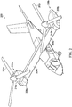
- FIG. 2 shows another tiltrotor aircraft 200 that utilizes the system in accordance with the present application.
- Tiltrotor aircraft 200 includes tilt rotor assemblies 202a and 202b that are carried by wings 204a and 204b, and are disposed at end portions 206a and 206b of wings 204a and 204b, respectively.
- Tilt rotor assemblies 202a and 202b include nacelles 208a and 208b, which include the engines and transmissions of tiltrotor aircraft 200.
- the engines are fixed to the wing and do not rotate, rather, only the pylons 210a and 210b with the tilt rotor assemblies 202a and 202b rotate.
- Tilt rotor assemblies 202a and 202b move and rotate relative to wing members 204a and 204b and the nacelles 208a and 208b.
- the tilt rotor assemblies 202a and 202b do not more relative to the wing members 204a and 204b. Instead, during the transition between a helicopter or hover mode only the pylons 210a and 210b with the tilt rotor assemblies 202a and 202b rotate to redirect the thrust from the tilt rotor assemblies 202a and 202b.
- the tiltrotor aircraft 200 is still able to fly like a conventional helicopter; and an airplane or cruise mode in which one of the rotors are tilted forward, such that tiltrotor aircraft 200 flies like a conventional propeller driven aircraft.
- the invention of a hybrid propulsion drive train system for tiltrotor aircraft which can be a stop-fold tiltrotor aircraft, that resolves the reliability and weight penalties of a mechanical propulsion system drive train by replacing gearboxes, drive shafts, clutches, and phasing units with redundant high-speed electric motors, electric generators and multiple electrics power distribution busses.
- the hybrid propulsion drive train system may be configured using redundant high-speed hydraulic motors, hydraulic pumps and multiple hydraulic power distribution systems. The skilled artisan will recognize that a combination of both the electric and hydraulic system may also be used in certain configurations.
- Hybrid propulsion as configured in this invention eliminates the use of gearboxes and drive shafts to distribute power from the engine to the prop rotors.
- a turbo shaft engine is connected to a reduction gearbox that drives redundant electric generators (e.g., high-speed electric generators) or hydraulic pumps to provide electric or hydraulic power, respectively.
- Power from the electric generators or hydraulic pumps is conveyed, respectively, to electric or hydraulic motors on the pylons that drive the proprotor gearboxes via multiple electrics power distribution busses or multiple hydraulic power distribution systems.
- the application of redundant electric and/or hydraulic power distribution systems supports required safety/reliability requirements while providing for simplified airframe routing over mechanical drive shafts.
- the hybrid power drive train system provides for variable speed operation of the rotors down to zero RPM, thus, the requirement for a high-speed clutch and a rotor-phasing unit is eliminated.
- the present invention includes a hybrid propulsion drive train system that does not include or require a high-speed clutch and/or a rotor-phasing unit.
- the hybrid propulsion drive train system for tiltrotor aircraft of the present invention utilizes existing internal combustion, jet, or turbo shaft engine technology, thereby the eliminating the requirement for a convertible engine.
- distributed propulsion Power generated from engines, such as a turbo shaft engine, is transmitted to the ducted fans utilizing electric generators on the engine to power electric motors on the variable speed ducted fans.
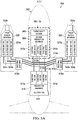
- FIG. 3A shows a top-view of an electric hybrid propulsion drive train system of the present invention that incorporates distributed propulsion to provide thrust for high speed and efficient forward flight using ducted fans.
- Aircraft 300 is depicted having a fuselage 302 and nacelles 304a, 304b.
- the fuselage 302 includes one or more engines 306, which is depicted in this embodiment as a single turbo shaft engine that is connected to an engine reduction gearbox 308.
- the skilled artisan will recognize that for purposes of redundancy the aircraft 300 can include more than one engine as depicted in the insert.
- the engine reduction gearbox 308 connected to one or more electric generators (in this version three electric generators 310a, 310b, and 310c are depicted) that convert shaft power from the turbo shaft engine 306 into electrical power.
- the electric generators 310a, 310b, and 310c are connected, respectively, to power conduits 312a, 312b, 312c.
- Power conduit 312a is connected to electric motors 313a, 320a and 324a.
- Power conduit 312b is connected to electric motors 313b, 320b and 324b.
- Power conduit 312c is connected to electric motors 313c, 320c and 324c.
- the aircraft 300 may be a tiltrotor aircraft and the nacelles 304a, 304b tilt, which can require, e.g., an electric slip ring 318a, 318b, respectively, to connect power conduits 312a, 312b, 312c to the respective electric motors.
- the various electric generators 310a, 310b, 310c power a single large electric motor, however, for applications in which redundancy is preferred (such as manned aircraft), it will be common to include 1, 2, 3, 4, or more electric motors.
- the number of electric motors can be optimized by factoring the weight of the electric motor, the speed of the electric motor, the torque of the electric motor, the weight of the aircraft, etc.
- the electric motors 313a, 313b, and 313c are depicted as driving a reduction gearbox 314 that connected to a ducted fan 316 that is used to provide additional thrust to the aircraft 300.
- a ducted fan 316 is depicted in this embodiment as being in the back of the aircraft 300, the skilled artisan will recognize that it may be positioned in front of the engine 306, adjacent to the engine 306 or may include more than one ducted fan 316, such as 1, 2, 3, 4, or more ducted fans.
- each of the nacelles 304a, 304b each is depicted with three electric motors, however the skilled artisan will recognize that the number of electric motors can be varied depending on power-to-weight curves or restrictions, such as 1, 2, 3, 4, or more electric motors.
- the electric motors 320a, 320b, and 320c are depicted in nacelles 304a connected to drive a prop rotor gearbox 322 that turns a proprotor (not depicted).
- the electric motors 324a, 324b, and 324c are depicted in nacelles 304b to connect to and drive a prop rotor gearbox 326 that turns a proprotor (not depicted).
- the two nacelles 304a, 304b are used in a traditional manner as with all tiltrotor or vertical take off and landing craft to provide lift when the proprotors are parallel to the ground and upon take off will rotate to a position generally perpendicular to the flight during forward flight providing thrust.
- the proprotors may be used primarily for the initial take-off and landing, but the ducted fan 316 may provide addition thrust or be the primary or sole source of thrust during forward flight.
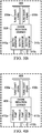
- FIG. 3B shows the turbo shaft engine 306 in an expanded view that depicts two turbo shaft engines 330a, 330b, that connect to the engine reduction gearbox 308.
- the aircraft 300 may include 1, 2, 3, 4, or more engines.
- the engines may be conventional jet engines or even standard combustion engines, so long as they provide shaft power to drive the reduction gearbox 314 that provides power to ducted fan 316.
- FIG. 4A shows a top-view of a hydraulic hybrid propulsion drive train system of the present invention that incorporates distributed propulsion to provide thrust for high speed and efficient forward flight using ducted fans.
- Aircraft 400 is depicted having a fuselage 402 and nacelles 404a, 404b.
- the fuselage 402 includes one or more engines 406, which is depicted in this embodiment as a single turbo shaft engine that is connected to an engine reduction gearbox 408.
- the skilled artisan will recognize that for purposes of redundancy the aircraft 400 can include more than one engine as depicted in the insert.
- the engine reduction gearbox 408 connected to one or more hydraulic pumps (in this version three hydraulic pumps 410a, 410b, and 410c are depicted) that convert shaft power from the turbo shaft engine 406 into hydraulic power.
- the hydraulic pumps 410a, 410b and 410c are connected, respectively, to hydraulic fluid conduits 412a, 412b, 412c.
- Hydraulic fluid conduit 412a is connected to hydraulic motors 413a, 420a and 424a.
- Hydraulic fluid conduit 412b is connected to hydraulic motors 413b, 420b and 424b.
- Hydraulic fluid conduit 412c is connected to hydraulic motors 413c, 420c and 424c.
- the aircraft 400 may be a tiltrotor aircraft and the nacelles 404a, 404b tilt, which can require, e.g., an hydraulic swivels 418a, 418b, respectively, to connect hydraulic fluid conduits 412a, 412b, 412c to the respective hydraulic motors.
- the various hydraulic pumps 410a, 410b, 410c power a single large hydraulic motor, however, for applications in which redundancy is preferred (such as manned aircraft), it will be common to include 1, 2, 3, 4, or more hydraulic motors.
- the number of hydraulic motors can be optimized by, e.g., factoring the weight of the hydraulic motor, the speed of the hydraulic motor, the torque of the hydraulic motor, the weight of the aircraft, etc.
- the hydraulic motors 413a, 413b, and 413c are depicted as driving a reduction gearbox 414 that connected to a ducted fan 416 that is used to provide additional thrust to the aircraft 400.
- a ducted fan 416 is depicted in this embodiment as being in the back of the aircraft 400, the skilled artisan will recognize that it may be positioned in front of the engine 406, adjacent to the engine 406 or may include more than one ducted fan 416, such as 1, 2, 3, 4, or more ducted fans.
- each of the nacelles 404a, 404b each is depicted with three hydraulic motors, however the skilled artisan will recognize that the number of hydraulic motors can be varied depending on power-to-weight curves or restrictions, such as 1, 2, 3, 4, or more hydraulic motors.
- the hydraulic motors 420a, 420b and 420c are depicted in nacelles 404a connected to drive a prop rotor gearbox 422 that turns a proprotor (not depicted).
- the hydraulic motors 424a, 424b and 424c are depicted in nacelles 404b to connect to and drive a prop rotor gearbox 426 that turns a proprotor (not depicted).
- the two nacelles 404a, 404b are used in a traditional manner as with all tiltrotor or vertical take off and landing craft to provide lift when the proprotors are parallel to the ground and upon take off will rotate to a position generally perpendicular to the flight during forward flight providing thrust.
- the proprotors may be used primarily for the initial take-off and landing, but the ducted fan 416 may provide addition thrust or be the primary or sole source of thrust during forward flight.
- FIG. 4B shows turbo shaft engine 406 in an expanded view that depicts two turbo shaft engines 430a, 430b, which connect to the engine reduction gearbox 408.
- the aircraft 400 may include 1, 2, 3, 4, or more engines.
- the engines may be conventional jet engines or even standard combustion engines, so long as they provide shaft power to drive the reduction gearbox 414 that provides power to ducted fan 416.
- the present invention also includes the combination of both electric generators connected to electric motors, and hydraulic pumps connected to hydraulic motors on the same aircraft. While generally only one type of torque-converting power will typically be used, it is possible that certain configurations, size, weight, and torque requirements may include at least one or more electric and one or more hydraulic system(s) in the same aircraft.
- FIG. 5A shows a top-view of an electric hybrid propulsion drive train system of the present invention that incorporates distributed propulsion to provide thrust for high speed and efficient forward flight using ducted fans.
- Aircraft 500 is depicted having a fuselage 302 and nacelles 304a, 304b.
- the fuselage 302 includes one or more engines 306, which is depicted in this embodiment as a single turbo shaft engine that is connected to an engine reduction gearbox 308.
- the skilled artisan will recognize that for purposes of redundancy the aircraft 500 can include more than one engine as depicted in the insert.
- the engine reduction gearbox 308 connected to one or more electric generators (in this version three electric generators 310a, 310b, and 310c are depicted) that convert shaft power from the turbo shaft engine 306 into electrical power.
- the electric generators 310a, 310b, and 310c are connected, respectively, to power conduits 312a, 312b, 312c.
- Power conduit 312a is connected to electric motors 313a, 502a and 506a.
- Power conduit 312b is connected to electric motors 313b, 502b and 506b.
- Power conduit 312c is connected to electric motors 313c, 502c and 506c.
- the aircraft 500 may be a tiltrotor aircraft and the nacelles 304a, 304b tilt, which can require, e.g., an electric slip ring 318a, 318b, respectively, to connect power conduits 312a, 312b, 312c to the respective electric motors.
- the various electric generators 310a, 310b, 310c power a single large electric motor, however, for applications in which redundancy is preferred (such as manned aircraft), it will be common to include 1, 2, 3, 4, or more electric motors.
- the number of electric motors can be optimized by factoring the weight of the electric motor, the speed of the electric motor, the torque of the electric motor, the weight of the aircraft, etc.
- the electric motors 313a, 313b, and 313c are directly connected to a ducted fan 316 that is used to provide additional thrust to the aircraft 500.
- a ducted fan 316 is depicted in this embodiment as being in the back of the aircraft 500, the skilled artisan will recognize that it may be positioned in front of the engine 306, adjacent to the engine 306 or may include more than one ducted fan 316, such as 1, 2, 3, 4, or more ducted fans.
- the nacelles 304a, 304b each is depicted with three electric motors, however the skilled artisan will recognize that the number of electric motors can be varied depending on power-to-weight curves or restrictions, such as 1, 2, 3, 4, or more electric motors.
- the electric motors 502a, 502b and 502c are depicted in nacelles 304a connected directly to the prop mast 504a.
- the electric motors 502a, 502b and 502c will be sized to provide partial or full torque to the prop mast 504a directly.
- electric motors 506a, 506b and 506c are depicted in nacelles 304b connected directly to the prop mast 504b.
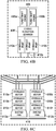
- FIG. 5B shows the turbo shaft engine 306 in an expanded view that depicts two turbo shaft engines 330a, 330b, that connect to the engine reduction gearbox.
- the aircraft 500 may include 1, 2, 3, 4, or more engines.
- the engines may be conventional jet engines or even standard combustion engines, so long as they provide shaft power to drive the reduction gearbox 308.
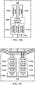
- FIG. 5C shows that the ducted fan 316 can include, in this embodiment, two ducted fans 512a, 512b, which are respectively driven directly by electric motors, in the case of ducted fan 512a connected to electric motors 510a, 510b, 510c, and in the case of ducted fan 512b connected to electric motors 510d, 510e, 510f.
- FIG. 6A shows a top-view of a hydraulic hybrid propulsion drive train system of the present invention that incorporates distributed propulsion to provide thrust for high speed and efficient forward flight using ducted fans.
- Aircraft 600 is depicted having a fuselage 402 and nacelles 404a, 404b.
- the fuselage 402 includes one or more engines 406, which is depicted in this embodiment as a single turbo shaft engine that is connected to an engine reduction gearbox 408.
- the skilled artisan will recognize that for purposes of redundancy the aircraft 600 can include more than one engine as depicted in the insert.
- the engine reduction gearbox 408 connected to one or more hydraulic pumps (in this version three hydraulic pumps 410a, 410b and 410c are depicted) that convert shaft power from the turbo shaft engine 406 into hydraulic power.
- the hydraulic pumps 410a, 410b and 410c are connected, respectively, to hydraulic fluid conduits 412a, 412b and 412c.
- Hydraulic fluid conduit 412a is connected to hydraulic motors 413a, 602a and 606a.
- Hydraulic fluid 412b is connected to hydraulic motors 413b, 602b and 606b.
- Hydraulic fluid 412c is connected to hydraulic motors 413c, 602c and 606c.
- the aircraft 600 may be a tiltrotor aircraft and the nacelles 404a, 404b tilt, which can require, e.g., a hydraulic swivels 418a, 418b, respectively, to connect hydraulic fluid conduits 412a, 412b and 412c to the respective hydraulic motors.
- the various hydraulic pumps 410a, 410b power a single large hydraulic motor, however, for applications in which redundancy is preferred (such as manned aircraft), it will be common to include 1, 2, 3, 4, or more hydraulic motors.
- the number of hydraulic motors can be optimized by, e.g., factoring the weight of the hydraulic motor, the speed of the hydraulic motor, the torque of the hydraulic motor, the weight of the aircraft, etc.
- the hydraulic motors 413a, 413b and 413c are driving directly a ducted fan 416 that is used to provide additional thrust to the aircraft 600.
- the ducted fan 416 is depicted in this embodiment as being in the back of the aircraft 600, the skilled artisan will recognize that it may be positioned in front of the engine 406, adjacent to the engine 406 or may include more than one ducted fan 416, such as 1, 2, 3, 4, or more ducted fans.
- the nacelles 404a, 404b each is depicted with three hydraulic motors, however the skilled artisan will recognize that the number of hydraulic motors can be varied depending on power-to-weight curves or restrictions, such as 1, 2, 3, 4, or more hydraulic motors.
- the hydraulic motors 602a, 602b and 602c are depicted in nacelles 404a connected directly to the prop mast 604a.
- the hydraulic motors 602a, 602b and 602c will be sized to provide partial or full torque to the prop mast 604a directly.
- hydraulic motors 606a, 606b and 606c are depicted in nacelles 404b connected directly to the prop mast 604b.
- FIG. 6B shows the turbo shaft engine 406 in an expanded view that depicts two turbo shaft engines 430a, 430b, that connect to the engine reduction gearbox 408.
- the aircraft 600 may include 1, 2, 3, 4, or more engines.
- the engines may be conventional jet engines or even standard combustion engines, so long as they provide shaft power to drive the engine reduction gearbox 408.
- FIG. 6C shows that the ducted fan 416 can include, in this embodiment, two ducted fans 612a, 612b, which are respectively driven directly by hydraulic motors, in the case of ducted fan 612a connected to hydraulic motors 610a, 610b, 610c, and in the case of ducted fan 612b connected to hydraulic motors 610d, 610e, 610f.
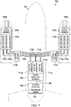
- FIG. 7 shows a top-view of an electric hybrid propulsion drive train system of the present invention that incorporates distributed propulsion to provide thrust for high speed and efficient forward flight using ducted fans.
- Aircraft 700 is depicted having a fuselage 302 and nacelles 304a, 304b.
- the fuselage 302 includes one or more engines, which is depicted in this embodiment as a high bypass engine 702 that is connected by shaft 706 to an engine reduction gearbox 708.
- the high bypass engine 702 can be connected directly or indirectly to a variable pitch fan 704, but also provide shaft power via shaft 706 to an engine reduction gearbox 708.
- the engine reduction gearbox 708 is connected to one or more electric generators (in this version three electric generators 710a, 710b and 710c are depicted) that convert shaft power from the high bypass engine 702 into electrical power.
- the electric generators 710a, 710b and 710c are connected, respectively, to power conduits 712a, 712b, 712c.
- Power conduit 712a is connected to electric motors 718a and 722a.
- Power conduit 712b is connected to electric motors 718b and 722b.
- Power conduit 712c is connected to electric motors 718c and 722c.
- the aircraft 700 may be a tiltrotor aircraft and the nacelles 304a, 304b tilt, which can require, e.g., an electric slip ring 716a, 716b, respectively, to connect power conduits 712a, 712b, 712c to the respective electric motors.
- the various electric generators 710a, 710b, 710c power a single large electric motor, however, for applications in which redundancy is preferred (such as manned aircraft), it will be common to include 1, 2, 3, 4, or more electric motors.
- the number of electric motors can be optimized by factoring the weight of the electric motor, the speed of the electric motor, the torque of the electric motor, the weight of the aircraft, etc.
- variable pitch fan 704 is depicted in this embodiment as being in front of the high bypass engine 702, the skilled artisan will recognize that it may be positioned rearward from the high bypass engine 702. Further, while depicted as a single variable pitch fan 704, variable pitch fan 704 may include more than one ducted fan, such as 2, 3, 4, or more ducted fans, which can also be positioned adjacent the high bypass engine 702 or elsewhere on the aircraft 700.
- each of the nacelles 304a, 304b each is depicted with three electric motors, however the skilled artisan will recognize that the number of electric motors can be varied depending on power-to-weight curves or restrictions, such as 1, 2, 3, 4, or more electric motors.
- the electric motors 718a, 718b and 718c are depicted in nacelles 304a connected to drive a proprotor reduction gearbox 720a that turns a proprotor (not depicted).
- the electric motors 722a, 722b and 722c are depicted in nacelles 304b to connect to and drive a proprotor reduction gearbox 720b that turns a proprotor (not depicted).
- the two nacelles 304a, 304b are used in a traditional manner as with all tiltrotor or vertical take off and landing craft to provide lift when the proprotors are parallel to the ground and upon take off will rotate to a position generally perpendicular to the flight during forward flight providing thrust.
- the proprotors may be used primarily for the initial take-off and landing, but the variable pitch fan 704 may provide addition thrust or be the primary or sole source of thrust during forward flight.
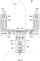
- FIG. 8 shows a top-view of a hydraulic hybrid propulsion drive train system of the present invention that incorporates distributed propulsion to provide thrust for high speed and efficient forward flight using ducted fans.
- Aircraft 800 is depicted having a fuselage 402 and nacelles 404a, 404b.
- the fuselage 402 includes one or more engines, which is depicted in this embodiment as a high bypass engine 802 that is connected by a shaft 806 to an engine reduction gearbox 808.
- the high bypass engine 802 can be connected directly or indirectly to a variable pitch fan 804, but also provide shaft power via shaft 806 to an engine reduction gearbox 808.
- the engine reduction gearbox 808 is connected to one or more hydraulic pumps (in this version three hydraulic pumps 810a, 810b and 810c are depicted) that convert shaft power from the high bypass engine 802 into hydraulic power.
- the hydraulic pumps 810a, 810b and 810c are connected, respectively, to hydraulic conduits 812a, 812b, 812c.
- Hydraulic conduit 812a is connected to hydraulic motors 818a and 822a.
- Hydraulic conduit 812b is connected to hydraulic motors 818b and 822b.
- Hydraulic conduit 812c is connected to hydraulic motors 818c and 822c.
- the aircraft 800 may be a tiltrotor aircraft and the nacelles 404a, 404b tilt, which can require, e.g., hydraulic swivels 814a, 814b, respectively, to connect hydraulic conduits 812a, 812b, 812c to the respective hydraulic motors.
- the various hydraulic pumps 810a, 810b, 810c power a single large hydraulic motor, however, for applications in which redundancy is preferred (such as manned aircraft), it will be common to include 1, 2, 3, 4, or more hydraulic motors.
- the number of hydraulic motors can be optimized by factoring the weight of the hydraulic motor, the speed of the hydraulic motor, the torque of the hydraulic motor, the weight of the aircraft, etc.
- variable pitch fan 804 is depicted in this embodiment as being in front of the high bypass engine 802, the skilled artisan will recognize that it may be positioned rearward from the high bypass engine 802. Further, while depicted as a single variable pitch fan 804, variable pitch fan 804 may include more than one ducted fan, such as 2, 3, 4, or more ducted fans, which can also be positioned adjacent the high bypass engine 802 or elsewhere on the aircraft 800.
- each of the nacelles 404a, 404b each is depicted with three hydraulic motors, however the skilled artisan will recognize that the number of hydraulic motors can be varied depending on power-to-weight curves or restrictions, such as 1, 2, 3, 4, or more hydraulic motors.
- the hydraulic motors 818a, 818b and 818c are depicted in nacelles 404a connected to drive a prop rotor reduction gearbox 820a that turns a proprotor (not depicted).
- the hydraulic motors 822a, 822b and 822c are depicted in nacelles 404b to connect to and drive a prop rotor reduction gearbox 820b that turns a proprotor (not depicted).
- the two nacelles 404a, 404b are used in a traditional manner as with all tiltrotor or vertical take off and landing craft to provide lift when the proprotors are parallel to the ground and upon take off will rotate to a position generally perpendicular to the flight during forward flight providing thrust.
- the proprotors may be used primarily for the initial take-off and landing, but the variable pitch fan 804 may provide addition thrust or be the primary or sole source of thrust during forward flight.
- the present invention may be a hybrid propulsion drive train system in which a stop-fold tiltrotor converts from helicopter to high-speed airplane mode, as follows: (a) conversion from helicopter to low speed airplane mode: generators/pumps transmit power to proprotor electric/hydraulic motors as pylons are rotated into airplane mode and speed is increased; (b) one or more ducted fans are not powered to reduce forward thrust; and/or (c) conversion from low to high speed airplane mode: generators/pumps provide increasing power to ducted fans to generate forward thrust as power to proprotors is decreased to zero. If the proprotors are stop-fold tiltrotors, the proprotors are folded during forward flight to reduce drag. Providing power for stopping and setting to folding proprotor folding index position can be provided by the proprotor electric/hydraulic motors. Finally, in full forward flight, power to the ducted fans is increased to allow for maximum speed.
- hybrid propulsion drive train systems are possible utilizing high torque electric and hydraulic motors.
- FIG. 5A for high torque electric and FIG. 6A for high torque hydraulic hybrid propulsion drive train systems incorporation high torque motor technology allows for the elimination of prop rotor and ducted fan reduction gearboxes. Elimination of prop rotor and ducted fan reduction gearboxes improves aircraft reliability and reduces weight.
- Another implementation of hybrid propulsion drive train systems is possible utilizing a high bypass jet engine with a variable pitch fan combined with either electric or hydraulic motors. As shown in FIG. 7 for electric and FIG.
- incorporation variable pitch fan high bypass engine technology allows for the elimination of the ducted fan reduction gearbox and drive motors.
- power to a bypass fan would be minimized by reducing the pitch of the fan blade or the inlet vane, while the engine core maintains required airflow.
- Unloading the turbofan from the generators or pumps in high-speed airplane mode is the same as other configuration.
- the aircraft may combine any of the embodiments depicted in FIGS. 3A , 4A , 5A , 6A , 7 and 8 in a single aircraft.
- the aircraft may also include a stop-fold tiltrotor.
- the words “comprising” (and any form of comprising, such as “comprise” and “comprises"), “having” (and any form of having, such as “have” and “has”), “including” (and any form of including, such as “includes” and “include”) or “containing” (and any form of containing, such as “contains” and “contain”) are inclusive or open-ended and do not exclude additional, unrecited elements or method steps.
- “comprising” may be replaced with “consisting essentially of” or “consisting of”.
- the phrase “consisting essentially of” requires the specified integer(s) or steps as well as those that do not materially affect the character or function of the claimed invention.
- the term “consisting” is used to indicate the presence of the recited integer (e.g., a feature, an element, a characteristic, a property, a method/process step or a limitation) or group of integers (e.g., feature(s), element(s), characteristic(s), propertie(s), method/process steps or limitation(s)) only.
- words of approximation such as, without limitation, "about”, “substantial” or “substantially” refers to a condition that when so modified is understood to not necessarily be absolute or perfect but would be considered close enough to those of ordinary skill in the art to warrant designating the condition as being present.
- the extent to which the description may vary will depend on how great a change can be instituted and still have one of ordinary skilled in the art recognize the modified feature as still having the required characteristics and capabilities of the unmodified feature.
- a numerical value herein that is modified by a word of approximation such as "about” may vary from the stated value by at least ⁇ 1, 2, 3, 4, 5, 6, 7, 10, 12 or 15%.
Landscapes
- Engineering & Computer Science (AREA)
- Aviation & Aerospace Engineering (AREA)
- Mechanical Engineering (AREA)
- General Engineering & Computer Science (AREA)
- Chemical & Material Sciences (AREA)
- Combustion & Propulsion (AREA)
- Transmission Devices (AREA)
- Wind Motors (AREA)
Abstract
Description
- This patent application claims priority to
U.S. provisional patent application serial number 62/465,934 filed on March 2, 2017 - Not applicable.
- The present invention relates in general to the field of aircraft, and more particularly, to a hybrid propulsion system for tiltrotor aircraft.
- Without limiting the scope of the invention, its background is described in connection with tiltrotor aircraft.
- United States Patent No.
7,571,879, issued to Builta, et al. , is entitled "Automatic conversion system for tiltrotor aircraft", and teaches a method for automatically controlling the conversion of a tiltrotor aircraft. An airspeed command for the tiltrotor aircraft is received. The airspeed command is converted to a pylon position, wherein a difference between the airspeed command and a measured airspeed is calculated. The difference between the airspeed command and a measured airspeed is converted to a dynamic pylon position, and a total pylon position is calculated from the pylon position and the dynamic pylon position. A pylon of the tiltrotor aircraft is moved to the total pylon position. Another embodiment of the present invention is a system for calculating a position of a pylon of a tiltrotor aircraft based on an airspeed command. The system includes an airspeed command module, a pylon trim position module, a dynamic pylon position module, and a pylon position module. - United States Patent No.
6,644,588, issued to King, et al. , is entitled, "Multi-mode tiltrotor nacelle control system with integrated envelope protection," and teaches a tiltrotor aircraft that has a multi-mode tiltrotor nacelle control system with integrated envelope protection. The tiltrotor aircraft has a fuselage, a tail section, a left wing member, a right wing member, a right engine nacelle, a left engine nacelle, a left proprotor, and a right proprotor. Activation of the nacelle control system causes preselected rotational movement of the tiltrotor assembly. - In one embodiment, the present invention includes a hybrid propulsion system for a tiltrotor craft comprising: one or more engines that drive a shaft; at least one of: one or more electrical generators or one or more hydraulic pumps, connected to the shaft of the one or more engines; and at least two rotatable nacelles, each nacelle housing at least one of: one or more electric motors or one or more hydraulic motors, each connected to a proprotor; wherein the one or more electric motors is electrically connected to the one or more electric generators, or the one or more hydraulic motors is connected to the one or more hydraulic pumps, respectively; and wherein the proprotors provide lift whenever the tiltrotor craft is in vertical takeoff and landing and stationary flight, and provide thrust whenever the tiltrotor craft is in forward flight. In one aspect, the tiltrotor craft is manned or unmanned. In another aspect, the one or more engines provide: direct, distributed, or direct and distributed, thrust during forward flight. In another aspect, the system further comprises one or more ducted fans, one or more variable pitch fans, or both, wherein the one or more ducted fans or the one or more variable pitch fans, or both, are connected to an electric motor, a hydraulic motor, or both, to provide additional thrust during forward flight. In another aspect, the system further comprises one or more ducted fans, one or more variable pitch fans, or both, wherein the one or more engines are directly connected via an electrical generator and electric motor, or a hydraulic pump and hydraulic motor, or both, to the one or more ducted fans. In another aspect, the system further comprises one or more ducted fans, one or more variable pitch fans, or both, wherein the one or more engines are indirectly connected via an electrical generator and electric motor, or a hydraulic pump and hydraulic motor, or both, to the one or more ducted fans. In another aspect, the system further comprises one or more ducted fans, one or more variable pitch fans, or both, wherein the one or more engines are connected to an electrical generator that is electrically connected to an electric motor, wherein the electric motor is connected to a variable pitch fan or ducted fan that provides additional thrust during forward flight, wherein the electric motor drives the one or more variable pitch fans or ducted fans that are positioned at least one of upstream, adjacent to, or downstream from, the one or more engines. In another aspect, the system further comprises one or more ducted fans, one or more variable pitch fans, or both, wherein the one or more engines are connected to a hydraulic pump that is hydraulically connected to a hydraulic motor, wherein the hydraulic motor is connected to a variable pitch fan or ducted fan that provides additional thrust during forward flight, wherein the hydraulic motor drives the one or more variable pitch fans or ducted fans that are positioned at least one of upstream, adjacent to, or downstream from, the one or more engines. In another aspect, the one or more engines comprise a turboshaft engine or a high bypass engine. In another aspect, the system further comprises a reduction gearbox positioned between the one or more engines and the one or more electrical generators or the one or more hydraulic pumps. In another aspect, the system further comprises a proprotor reduction gearbox positioned between at least one of: the one or more electrical motors or the one or more hydraulic motors, or both, and the proprotor. In another aspect, the proprotors are driven directly by the at least of: one or more electrical motors, the one or more hydraulic motors, or both. In another aspect, the one or more engines are defined further as one or more turboshaft engines, or one or more distributed engines that are not mechanically connected to one or more rotors or fans, wherein the one or more turboshaft engines or the one or more distributed engines provide additional thrust during forward flight. In another aspect, the system further comprises an electric slip ring that electrically connects the one or more electrical generators to the one or more electrical motors in each of the nacelles. In another aspect, the system further comprises a hydraulic swivel that hydraulically connects the one or more hydraulic pumps to the one or more hydraulic motors in each of the nacelles. In another aspect, the tiltrotor craft comprises, respectively: one to four electric generators connected to the one or more engines and connected one to four electric motors in each nacelle, or, one to four hydraulic pumps connected to the one or more turboshaft engines and connected to one to four hydraulic motors in each nacelle, or a combination thereof. In another aspect, each of the proprotors are stop-fold proprotors.
- In another embodiment, the present invention includes a method of providing propulsion to a tiltrotor craft comprising: providing one or more engines comprising a shaft; driving one or more electrical generators, one or more hydraulic pumps, or both, each connected to the shaft of the engine; and providing at least two nacelles, each nacelle comprising at least one of: one or more electric motors or one or more hydraulic motors each connected to a proprotor, wherein the electric motor is electrically connected to the electric generator, or the hydraulic motor is connected to the hydraulic pump, respectively; generating an electrical power from the electrical generators, or a hydraulic power from the hydraulic pumps; transmitting electrical power to the electric motors in the nacelles, or hydraulic power to the hydraulic motors in the nacelles, or both; and rotating the proprotors using the electrical motors, the hydraulic motors, or both, to provide lift whenever the tiltrotor craft is in vertical takeoff and landing and stationary flight, and to provide forward thrust whenever the tiltrotor craft is in forward flight. In one aspect, the tiltrotor craft is manned or unmanned. In another aspect, the one or more engines provide: direct, distributed, or direct and distributed, thrust during forward flight. In another aspect, each of the nacelles is rotatable. In another aspect, the method further comprises connecting one or more ducted fans, one or more variable pitch fans, or both, wherein the one or more ducted fans or the one or more variable pitch fans, or both, are connected to an electric motor, a hydraulic motor, or both, to provide additional thrust during forward flight. In another aspect, the method further comprises directly connecting one or more ducted fans, one or more variable pitch fans, or both, to the one or more engines via an electrical generator and electric motor, or a hydraulic pump and hydraulic motor, or both, to provide additional thrust during forward flight. In another aspect, the method further comprises indirectly connecting one or more ducted fans, one or more variable pitch fans, or both, to the one or more engines via an electrical generator and electric motor, or a hydraulic pump and hydraulic motor, or both, to provide additional thrust during forward flight. In another aspect, the method further comprises connecting one or more ducted fans, one or more variable pitch fans, or both, to the one or more engines via an electrical generator that is electrically connected to an electric motor, wherein the electric motor drives the one or more variable pitch fans or ducted fans that are positioned at least one of upstream, adjacent to, or downstream from, the one or more engines. In another aspect, the method further comprises connecting one or more ducted fans, one or more variable pitch fans, or both, to the one or more engines via a hydraulic pump that is hydraulically connected to a hydraulic motor, wherein the hydraulic motor drives the one or more variable pitch fans or ducted fans that are positioned at least one of upstream, adjacent to, or downstream from, the one or more engines. In another aspect, the one or more engines comprise a turboshaft engine or a high bypass engine. In another aspect, the method further comprises positioning a reduction gearbox between the one or more engines and the one or more electrical generators or the one or more hydraulic pumps. In another aspect, the method further comprises positioning a proprotor reduction gearbox between at least one of: the one or more electrical motors or the one or more hydraulic motors, or both, and the proprotor. In another aspect, the method further comprises directly driving each of the proprotors with the at least of: one or more electrical motors, the one or more hydraulic motors, or both. In another aspect, the one or more engines are defined further as: one or more turboshaft engines or one or more distributed engines that are not mechanically connected to one or more rotors or fans, wherein the one or more turboshaft engines or the one or more distributed engines provide additional thrust during forward flight. In another aspect, the method further comprises positioning an electric slip ring to electrically connect the one or more electrical generators to the one or more electrical motors in the nacelles. In another aspect, the method further comprises positioning a hydraulic swivel to hydraulically connect the one or more hydraulic pumps to the one or more hydraulic motors in the nacelles. In another aspect, the tiltrotor craft comprises, respectively: one to four electric generators connected to the one or more engines and connected one to four electric motors in each nacelle, or, one to four hydraulic pumps connected to the one or more turboshaft engines and connected to one to four hydraulic motors in each nacelle, or a combination thereof. In another aspect, each of the proprotors are stop-fold proprotors.
- In yet another embodiment, the present invention includes a hybrid propulsion system for an aircraft comprising: a turboshaft engine that provides shaft power and distributed thrust, wherein the turboshaft engine is connected directly or indirectly to one or more ducted fans, one or more variable pitch fans, or both, wherein the one or more ducted fans or the one or more variable pitch fans, or both, provide a first thrust during forward flight; at least one of: one or more electrical generators or one or more hydraulic pumps connected to the shaft of the turboshaft engine; and at least two nacelles, each nacelle comprising at least one of: one or more electric motors or one or more hydraulic motors each connected to a proprotor, wherein the electric motor is electrically connected to the electric generator, or the hydraulic motor is connected to the hydraulic pump, respectively, wherein the proprotors provide lift whenever the aircraft is in vertical takeoff and landing and stationary flight, and provide a second thrust whenever the aircraft is in forward flight.
- For a more complete understanding of the features and advantages of the present invention, reference is now made to the detailed description of the invention along with the accompanying figures and in which:
-
FIG. 1 shows a perspective view of a tiltrotor aircraft that can use the present application; -
FIG. 2 shows a perspective view of another tiltrotor aircraft that can also use the present application; -
FIGS. 3A and3B show top views of a tiltrotor high speed motor hybrid electric propulsion system of the present invention; -
FIGS. 4A and4B show top views of a tiltrotor high speed motor hybrid hydraulic propulsion system of the present invention; -
FIGS. 5A to 5C show top views of a tiltrotor high torque motor hybrid electric propulsion system of the present invention; -
FIGS. 6A to 6C show top views of a tiltrotor high torque motor hybrid hydraulic propulsion system of the present invention; -
FIG. 7 shows a top view of a tiltrotor high bypass engine hybrid electric propulsion system of the present invention; -
FIG. 8 shows a top view of a tiltrotor high bypass engine hybrid hydraulic propulsion system of the present invention. - Illustrative embodiments of the system of the present application are described below. In the interest of clarity, not all features of an actual implementation are described in this specification. It will of course be appreciated that in the development of any such actual embodiment, numerous implementation-specific decisions must be made to achieve the developer's specific goals, such as compliance with system-related and business-related constraints, which will vary from one implementation to another. Moreover, it will be appreciated that such a development effort might be complex and time-consuming but would nevertheless be a routine undertaking for those of ordinary skill in the art having the benefit of this disclosure.
- In the specification, reference may be made to the spatial relationships between various components and to the spatial orientation of various aspects of components as the devices are depicted in the attached drawings. However, as will be recognized by those skilled in the art after a complete reading of the present application, the devices, members, apparatuses, etc. described herein may be positioned in any desired orientation. Thus, the use of terms such as "above," "below," "upper," "lower," or other like terms to describe a spatial relationship between various components or to describe the spatial orientation of aspects of such components should be understood to describe a relative relationship between the components or a spatial orientation of aspects of such components, respectively, as the device described herein may be oriented in any desired direction.
- Helicopters are incredibly useful aircraft allowing for vertical takeoff, hovering and vertical landing. However, helicopter speed and range performance falls far short of that provided by conventional fixed wing airplanes. The development of tiltrotor technology has increased the speed rotorcraft speed to over 300 MPH (482 KPH) and extended range to approach the performance of conventional turboprop aircraft. Tiltrotor speed performance still falls short of what can be achieved by conventional jet propulsion aircraft.
- Jet fighter/attack aircraft such as the AV-8B Harrier and F-35 Lightning utilize jet thrust to provide vertical takeoff, hovering and vertical landing, and can obtain speeds of over 600 MPH (965 KPH). But the penalty for using jet thrust to provide vertical lift is dramatically reduced useful payload and range performance. Reduced payload and range performance is a direct consequence of the high disc loading (projected area of lift thrust) when using jet thrust to provide vertical lift. The relatively low disc loading of helicopters and tiltrotors allows for efficient vertical lift.
- In a conventional tiltrotor, a mechanical propulsion system drive train provides necessary safety, reliability, and operating performance at an acceptable weight. However, to support the unique operating requirements for a stop-fold tilt rotor, the addition of a high speed clutch, rotor phasing unit, and convertible engine can result in unacceptable loss of propulsion system reliability and an undesirable increase in aircraft weight.
- The hybrid propulsion system of the present invention can use a stop-fold proprotor, for conversion between helicopter and airplane modes by rotation of the pylons. With the stop fold tiltrotor operating in airplane mode, aircraft speed is increased further as the convertible engine transitions into a turbo jet to provide forward thrust and the rotors are slowed to a stop. Once the rotors are stopped they are folded back against the pylons to reduce aerodynamic drag and permit additional increase in speed.
-
FIG. 1 shows atiltrotor aircraft 100 that utilizes the system in accordance with the present application.Tiltrotor aircraft 100 includestilt rotor assemblies wings end portions wings Tilt rotor assemblies nacelles tiltrotor aircraft 100.Tilt rotor assemblies wing members rotor assemblies tiltrotor aircraft 100 flies like a conventional helicopter; and an airplane or cruise mode in which tiltrotor assemblies tiltrotor aircraft 100 flies like a conventional propeller driven aircraft. -
FIG. 2 shows anothertiltrotor aircraft 200 that utilizes the system in accordance with the present application.Tiltrotor aircraft 200 includestilt rotor assemblies wings end portions wings Tilt rotor assemblies nacelles tiltrotor aircraft 200. In this embodiment, the engines are fixed to the wing and do not rotate, rather, only thepylons tilt rotor assemblies Tilt rotor assemblies wing members nacelles tilt rotor assemblies wing members pylons tilt rotor assemblies tilt rotor assemblies tiltrotor aircraft 200 is still able to fly like a conventional helicopter; and an airplane or cruise mode in which one of the rotors are tilted forward, such thattiltrotor aircraft 200 flies like a conventional propeller driven aircraft. - The invention of a hybrid propulsion drive train system for tiltrotor aircraft, which can be a stop-fold tiltrotor aircraft, that resolves the reliability and weight penalties of a mechanical propulsion system drive train by replacing gearboxes, drive shafts, clutches, and phasing units with redundant high-speed electric motors, electric generators and multiple electrics power distribution busses. Alternatively, the hybrid propulsion drive train system may be configured using redundant high-speed hydraulic motors, hydraulic pumps and multiple hydraulic power distribution systems. The skilled artisan will recognize that a combination of both the electric and hydraulic system may also be used in certain configurations.
- Hybrid propulsion as configured in this invention eliminates the use of gearboxes and drive shafts to distribute power from the engine to the prop rotors. In one example, a turbo shaft engine is connected to a reduction gearbox that drives redundant electric generators (e.g., high-speed electric generators) or hydraulic pumps to provide electric or hydraulic power, respectively. Power from the electric generators or hydraulic pumps is conveyed, respectively, to electric or hydraulic motors on the pylons that drive the proprotor gearboxes via multiple electrics power distribution busses or multiple hydraulic power distribution systems. The application of redundant electric and/or hydraulic power distribution systems supports required safety/reliability requirements while providing for simplified airframe routing over mechanical drive shafts. The hybrid power drive train system provides for variable speed operation of the rotors down to zero RPM, thus, the requirement for a high-speed clutch and a rotor-phasing unit is eliminated. As such, the present invention includes a hybrid propulsion drive train system that does not include or require a high-speed clutch and/or a rotor-phasing unit.
- A major impediment to the development of a tiltrotor aircraft, such as a stop-fold tiltrotor aircraft, is the absence of an existing convertible engine capable of continuous overlapping transition between turbo-shaft and turbo-jet operating modes. The hybrid propulsion drive train system for tiltrotor aircraft of the present invention utilizes existing internal combustion, jet, or turbo shaft engine technology, thereby the eliminating the requirement for a convertible engine.
- In modern high bypass jet engines, the majority of the thrust is generated from a ducted fan in front of the engine, not from the flow of hot combustion gases passing through the engine as with early jet engines. Very large air-flow at relatively low differential to aircraft speed generated by the high bypass configuration increases engine efficiency, resulting in reduced fuel consumption. This is why commercial jet aircraft nacelles have grown in diameter with the demand for increased fuel efficiency. The greater the volume of bypass air, the greater the engine efficiency.
- To increase propulsion efficiency it is now possible to separate the fan from the engine completely, thus, locating the individual components in the aircraft to maximize aerodynamic efficiency and provide for variable fan speed operation. This is commonly known as "distributed propulsion". Power generated from engines, such as a turbo shaft engine, is transmitted to the ducted fans utilizing electric generators on the engine to power electric motors on the variable speed ducted fans.
-
FIG. 3A shows a top-view of an electric hybrid propulsion drive train system of the present invention that incorporates distributed propulsion to provide thrust for high speed and efficient forward flight using ducted fans.Aircraft 300 is depicted having afuselage 302 andnacelles fuselage 302 includes one ormore engines 306, which is depicted in this embodiment as a single turbo shaft engine that is connected to anengine reduction gearbox 308. Of course, the skilled artisan will recognize that for purposes of redundancy theaircraft 300 can include more than one engine as depicted in the insert. Theengine reduction gearbox 308 connected to one or more electric generators (in this version threeelectric generators turbo shaft engine 306 into electrical power. Theelectric generators power conduits 312c. Power conduit 312a is connected toelectric motors 324a. Power conduit 312b is connected toelectric motors 324b. Power conduit 312c is connected toelectric motors aircraft 300 may be a tiltrotor aircraft and thenacelles electric slip ring power conduits electric generators electric motors reduction gearbox 314 that connected to aducted fan 316 that is used to provide additional thrust to theaircraft 300. While theducted fan 316 is depicted in this embodiment as being in the back of theaircraft 300, the skilled artisan will recognize that it may be positioned in front of theengine 306, adjacent to theengine 306 or may include more than oneducted fan 316, such as 1, 2, 3, 4, or more ducted fans. Turning to each of thenacelles electric motors nacelles 304a connected to drive aprop rotor gearbox 322 that turns a proprotor (not depicted). Likewise, theelectric motors nacelles 304b to connect to and drive aprop rotor gearbox 326 that turns a proprotor (not depicted). Thus, the twonacelles ducted fan 316 may provide addition thrust or be the primary or sole source of thrust during forward flight.FIG. 3B shows theturbo shaft engine 306 in an expanded view that depicts twoturbo shaft engines engine reduction gearbox 308. Theaircraft 300 may include 1, 2, 3, 4, or more engines. Of course, in certain embodiments the engines may be conventional jet engines or even standard combustion engines, so long as they provide shaft power to drive thereduction gearbox 314 that provides power toducted fan 316. -
FIG. 4A shows a top-view of a hydraulic hybrid propulsion drive train system of the present invention that incorporates distributed propulsion to provide thrust for high speed and efficient forward flight using ducted fans.Aircraft 400 is depicted having afuselage 402 andnacelles fuselage 402 includes one ormore engines 406, which is depicted in this embodiment as a single turbo shaft engine that is connected to anengine reduction gearbox 408. Of course, the skilled artisan will recognize that for purposes of redundancy theaircraft 400 can include more than one engine as depicted in the insert. Theengine reduction gearbox 408 connected to one or more hydraulic pumps (in this version threehydraulic pumps turbo shaft engine 406 into hydraulic power. Thehydraulic pumps fluid conduits fluid conduit 412a is connected tohydraulic motors fluid conduit 412b is connected tohydraulic motors fluid conduit 412c is connected tohydraulic motors aircraft 400 may be a tiltrotor aircraft and thenacelles hydraulic swivels fluid conduits hydraulic pumps hydraulic motors reduction gearbox 414 that connected to aducted fan 416 that is used to provide additional thrust to theaircraft 400. While theducted fan 416 is depicted in this embodiment as being in the back of theaircraft 400, the skilled artisan will recognize that it may be positioned in front of theengine 406, adjacent to theengine 406 or may include more than oneducted fan 416, such as 1, 2, 3, 4, or more ducted fans. Turning to each of thenacelles hydraulic motors nacelles 404a connected to drive aprop rotor gearbox 422 that turns a proprotor (not depicted). Likewise, thehydraulic motors nacelles 404b to connect to and drive aprop rotor gearbox 426 that turns a proprotor (not depicted). Thus, the twonacelles ducted fan 416 may provide addition thrust or be the primary or sole source of thrust during forward flight.FIG. 4B showsturbo shaft engine 406 in an expanded view that depicts twoturbo shaft engines engine reduction gearbox 408. Theaircraft 400 may include 1, 2, 3, 4, or more engines. Of course, in certain embodiments the engines may be conventional jet engines or even standard combustion engines, so long as they provide shaft power to drive thereduction gearbox 414 that provides power toducted fan 416. - The present invention also includes the combination of both electric generators connected to electric motors, and hydraulic pumps connected to hydraulic motors on the same aircraft. While generally only one type of torque-converting power will typically be used, it is possible that certain configurations, size, weight, and torque requirements may include at least one or more electric and one or more hydraulic system(s) in the same aircraft.
-
FIG. 5A shows a top-view of an electric hybrid propulsion drive train system of the present invention that incorporates distributed propulsion to provide thrust for high speed and efficient forward flight using ducted fans.Aircraft 500 is depicted having afuselage 302 andnacelles fuselage 302 includes one ormore engines 306, which is depicted in this embodiment as a single turbo shaft engine that is connected to anengine reduction gearbox 308. Of course, the skilled artisan will recognize that for purposes of redundancy theaircraft 500 can include more than one engine as depicted in the insert. Theengine reduction gearbox 308 connected to one or more electric generators (in this version threeelectric generators turbo shaft engine 306 into electrical power. Theelectric generators power conduits 312c. Power conduit 312a is connected toelectric motors 506a. Power conduit 312b is connected toelectric motors 506b. Power conduit 312c is connected toelectric motors aircraft 500 may be a tiltrotor aircraft and thenacelles electric slip ring power conduits electric generators electric motors ducted fan 316 that is used to provide additional thrust to theaircraft 500. While theducted fan 316 is depicted in this embodiment as being in the back of theaircraft 500, the skilled artisan will recognize that it may be positioned in front of theengine 306, adjacent to theengine 306 or may include more than oneducted fan 316, such as 1, 2, 3, 4, or more ducted fans. Turning to each of thenacelles electric motors nacelles 304a connected directly to theprop mast 504a. Theelectric motors prop mast 504a directly. Likewise,electric motors nacelles 304b connected directly to theprop mast 504b.FIG. 5B shows theturbo shaft engine 306 in an expanded view that depicts twoturbo shaft engines aircraft 500 may include 1, 2, 3, 4, or more engines. Of course, in certain embodiments the engines may be conventional jet engines or even standard combustion engines, so long as they provide shaft power to drive thereduction gearbox 308.FIG. 5C shows that theducted fan 316 can include, in this embodiment, twoducted fans ducted fan 512a connected toelectric motors ducted fan 512b connected toelectric motors -
FIG. 6A shows a top-view of a hydraulic hybrid propulsion drive train system of the present invention that incorporates distributed propulsion to provide thrust for high speed and efficient forward flight using ducted fans.Aircraft 600 is depicted having afuselage 402 andnacelles fuselage 402 includes one ormore engines 406, which is depicted in this embodiment as a single turbo shaft engine that is connected to anengine reduction gearbox 408. Of course, the skilled artisan will recognize that for purposes of redundancy theaircraft 600 can include more than one engine as depicted in the insert. Theengine reduction gearbox 408 connected to one or more hydraulic pumps (in this version threehydraulic pumps turbo shaft engine 406 into hydraulic power. Thehydraulic pumps fluid conduits fluid conduit 412a is connected tohydraulic motors Hydraulic fluid 412b is connected tohydraulic motors Hydraulic fluid 412c is connected tohydraulic motors aircraft 600 may be a tiltrotor aircraft and thenacelles hydraulic swivels fluid conduits hydraulic pumps hydraulic motors ducted fan 416 that is used to provide additional thrust to theaircraft 600. While theducted fan 416 is depicted in this embodiment as being in the back of theaircraft 600, the skilled artisan will recognize that it may be positioned in front of theengine 406, adjacent to theengine 406 or may include more than oneducted fan 416, such as 1, 2, 3, 4, or more ducted fans. Turning to each of thenacelles hydraulic motors nacelles 404a connected directly to theprop mast 604a. Thehydraulic motors prop mast 604a directly. Likewise,hydraulic motors nacelles 404b connected directly to theprop mast 604b.FIG. 6B shows theturbo shaft engine 406 in an expanded view that depicts twoturbo shaft engines engine reduction gearbox 408. Theaircraft 600 may include 1, 2, 3, 4, or more engines. Of course, in certain embodiments the engines may be conventional jet engines or even standard combustion engines, so long as they provide shaft power to drive theengine reduction gearbox 408.FIG. 6C shows that theducted fan 416 can include, in this embodiment, twoducted fans ducted fan 612a connected tohydraulic motors ducted fan 612b connected tohydraulic motors -
FIG. 7 shows a top-view of an electric hybrid propulsion drive train system of the present invention that incorporates distributed propulsion to provide thrust for high speed and efficient forward flight using ducted fans.Aircraft 700 is depicted having afuselage 302 andnacelles fuselage 302 includes one or more engines, which is depicted in this embodiment as ahigh bypass engine 702 that is connected byshaft 706 to anengine reduction gearbox 708. Of course, the skilled artisan will recognize that for purposes of redundancy theaircraft 700 can include more than one engine. Thehigh bypass engine 702 can be connected directly or indirectly to avariable pitch fan 704, but also provide shaft power viashaft 706 to anengine reduction gearbox 708. Theengine reduction gearbox 708 is connected to one or more electric generators (in this version threeelectric generators high bypass engine 702 into electrical power. Theelectric generators power conduits 712c. Power conduit 712a is connected toelectric motors 718a and722a. Power conduit 712b is connected toelectric motors 718b and722b. Power conduit 712c is connected toelectric motors aircraft 700 may be a tiltrotor aircraft and thenacelles electric slip ring power conduits electric generators electric motors proprotor reduction gearbox 720a that is connected to a proprotor (not depicted). While thevariable pitch fan 704 is depicted in this embodiment as being in front of thehigh bypass engine 702, the skilled artisan will recognize that it may be positioned rearward from thehigh bypass engine 702. Further, while depicted as a singlevariable pitch fan 704,variable pitch fan 704 may include more than one ducted fan, such as 2, 3, 4, or more ducted fans, which can also be positioned adjacent thehigh bypass engine 702 or elsewhere on theaircraft 700. Turning to each of thenacelles electric motors nacelles 304a connected to drive aproprotor reduction gearbox 720a that turns a proprotor (not depicted). Likewise, theelectric motors nacelles 304b to connect to and drive aproprotor reduction gearbox 720b that turns a proprotor (not depicted). Thus, the twonacelles variable pitch fan 704 may provide addition thrust or be the primary or sole source of thrust during forward flight. -
FIG. 8 shows a top-view of a hydraulic hybrid propulsion drive train system of the present invention that incorporates distributed propulsion to provide thrust for high speed and efficient forward flight using ducted fans.Aircraft 800 is depicted having afuselage 402 andnacelles fuselage 402 includes one or more engines, which is depicted in this embodiment as ahigh bypass engine 802 that is connected by ashaft 806 to anengine reduction gearbox 808. Of course, the skilled artisan will recognize that for purposes of redundancy theaircraft 800 can include more than one engine. Thehigh bypass engine 802 can be connected directly or indirectly to avariable pitch fan 804, but also provide shaft power viashaft 806 to anengine reduction gearbox 808. Theengine reduction gearbox 808 is connected to one or more hydraulic pumps (in this version threehydraulic pumps high bypass engine 802 into hydraulic power. Thehydraulic pumps hydraulic conduits Hydraulic conduit 812a is connected tohydraulic motors Hydraulic conduit 812b is connected tohydraulic motors Hydraulic conduit 812c is connected tohydraulic motors aircraft 800 may be a tiltrotor aircraft and thenacelles hydraulic swivels hydraulic conduits hydraulic pumps hydraulic motors reduction gearbox 820a that connected to a proprotor (not depicted). While thevariable pitch fan 804 is depicted in this embodiment as being in front of thehigh bypass engine 802, the skilled artisan will recognize that it may be positioned rearward from thehigh bypass engine 802. Further, while depicted as a singlevariable pitch fan 804,variable pitch fan 804 may include more than one ducted fan, such as 2, 3, 4, or more ducted fans, which can also be positioned adjacent thehigh bypass engine 802 or elsewhere on theaircraft 800. Turning to each of thenacelles hydraulic motors nacelles 404a connected to drive a proprotor reduction gearbox 820a that turns a proprotor (not depicted). Likewise, thehydraulic motors nacelles 404b to connect to and drive a proprotor reduction gearbox 820b that turns a proprotor (not depicted). Thus, the twonacelles variable pitch fan 804 may provide addition thrust or be the primary or sole source of thrust during forward flight. - In certain additional embodiments, the present invention may be a hybrid propulsion drive train system in which a stop-fold tiltrotor converts from helicopter to high-speed airplane mode, as follows: (a) conversion from helicopter to low speed airplane mode: generators/pumps transmit power to proprotor electric/hydraulic motors as pylons are rotated into airplane mode and speed is increased; (b) one or more ducted fans are not powered to reduce forward thrust; and/or (c) conversion from low to high speed airplane mode: generators/pumps provide increasing power to ducted fans to generate forward thrust as power to proprotors is decreased to zero. If the proprotors are stop-fold tiltrotors, the proprotors are folded during forward flight to reduce drag. Providing power for stopping and setting to folding proprotor folding index position can be provided by the proprotor electric/hydraulic motors. Finally, in full forward flight, power to the ducted fans is increased to allow for maximum speed.
- Thus, in addition to the configurations described in
FIGS. 3A and4A using high-speed electric and hydraulic motors, additional implementations of hybrid propulsion drive train systems are possible utilizing high torque electric and hydraulic motors. As shown inFIG. 5A for high torque electric andFIG. 6A for high torque hydraulic hybrid propulsion drive train systems, incorporation high torque motor technology allows for the elimination of prop rotor and ducted fan reduction gearboxes. Elimination of prop rotor and ducted fan reduction gearboxes improves aircraft reliability and reduces weight. Another implementation of hybrid propulsion drive train systems is possible utilizing a high bypass jet engine with a variable pitch fan combined with either electric or hydraulic motors. As shown inFIG. 7 for electric andFIG. 8 for hydraulic hybrid propulsion drive train systems, incorporation variable pitch fan high bypass engine technology allows for the elimination of the ducted fan reduction gearbox and drive motors. In helicopter mode, power to a bypass fan would be minimized by reducing the pitch of the fan blade or the inlet vane, while the engine core maintains required airflow. Unloading the turbofan from the generators or pumps in high-speed airplane mode is the same as other configuration. The skilled artisan will recognize that for certain specific purposes, the aircraft may combine any of the embodiments depicted inFIGS. 3A ,4A ,5A ,6A ,7 and8 in a single aircraft. The aircraft may also include a stop-fold tiltrotor. - It will be understood that particular embodiments described herein are shown by way of illustration and not as limitations of the invention. The principal features of this invention can be employed in various embodiments without departing from the scope of the invention. Those skilled in the art will recognize, or be able to ascertain using no more than routine experimentation, numerous equivalents to the specific procedures described herein. Such equivalents are considered to be within the scope of this invention and are covered by the claims.
- All publications and patent applications mentioned in the specification are indicative of the level of skill of those skilled in the art to which this invention pertains. All publications and patent applications are herein incorporated by reference to the same extent as if each individual publication or patent application was specifically and individually indicated to be incorporated by reference.
- The use of the word "a" or "an" when used in conjunction with the term "comprising" in the claims and/or the specification may mean "one," but it is also consistent with the meaning of "one or more," "at least one," and "one or more than one." The use of the term "or" in the claims is used to mean "and/or" unless explicitly indicated to refer to alternatives only or the alternatives are mutually exclusive, although the disclosure supports a definition that refers to only alternatives and "and/or." Throughout this application, the term "about" is used to indicate that a value includes the inherent variation of error for the device, the method being employed to determine the value, or the variation that exists among the study subjects.
- As used in this specification and claim(s), the words "comprising" (and any form of comprising, such as "comprise" and "comprises"), "having" (and any form of having, such as "have" and "has"), "including" (and any form of including, such as "includes" and "include") or "containing" (and any form of containing, such as "contains" and "contain") are inclusive or open-ended and do not exclude additional, unrecited elements or method steps. In embodiments of any of the compositions and methods provided herein, "comprising" may be replaced with "consisting essentially of" or "consisting of". As used herein, the phrase "consisting essentially of" requires the specified integer(s) or steps as well as those that do not materially affect the character or function of the claimed invention. As used herein, the term "consisting" is used to indicate the presence of the recited integer (e.g., a feature, an element, a characteristic, a property, a method/process step or a limitation) or group of integers (e.g., feature(s), element(s), characteristic(s), propertie(s), method/process steps or limitation(s)) only.
- The term "or combinations thereof" as used herein refers to all permutations and combinations of the listed items preceding the term. For example, "A, B, C, or combinations thereof" is intended to include at least one of: A, B, C, AB, AC, BC, or ABC, and if order is important in a particular context, also BA, CA, CB, CBA, BCA, ACB, BAC, or CAB. Continuing with this example, expressly included are combinations that contain repeats of one or more item or term, such as BB, AAA, AB, BBC, AAABCCCC, CBBAAA, CABABB, and so forth. The skilled artisan will understand that typically there is no limit on the number of items or terms in any combination, unless otherwise apparent from the context.
- As used herein, words of approximation such as, without limitation, "about", "substantial" or "substantially" refers to a condition that when so modified is understood to not necessarily be absolute or perfect but would be considered close enough to those of ordinary skill in the art to warrant designating the condition as being present. The extent to which the description may vary will depend on how great a change can be instituted and still have one of ordinary skilled in the art recognize the modified feature as still having the required characteristics and capabilities of the unmodified feature. In general, but subject to the preceding discussion, a numerical value herein that is modified by a word of approximation such as "about" may vary from the stated value by at least ±1, 2, 3, 4, 5, 6, 7, 10, 12 or 15%.
- All of the devices and/or methods disclosed and claimed herein can be made and executed without undue experimentation in light of the present disclosure. While the devices and/or and methods of this invention have been described in terms of preferred embodiments, it will be apparent to those of skill in the art that variations may be applied to the compositions and/or methods and in the steps or in the sequence of steps of the method described herein without departing from the concept, spirit and scope of the invention. All such similar substitutes and modifications apparent to those skilled in the art are deemed to be within the spirit, scope and concept of the invention as defined by the appended claims.
- Furthermore, no limitations are intended to the details of construction or design herein shown, other than as described in the claims below. It is therefore evident that the particular embodiments disclosed above may be altered or modified and all such variations are considered within the scope and spirit of the disclosure. Accordingly, the protection sought herein is as set forth in the claims below.
- To aid the Patent Office, and any readers of any patent issued on this application in interpreting the claims appended hereto, applicants wish to note that they do not intend any of the appended claims to invoke paragraph 6 of 35 U.S.C. § 112 as it exists on the date of filing hereof unless the words "means for" or "step for" are explicitly used in the particular claim.
Claims (19)
- A hybrid propulsion system for a tiltrotor craft comprising:one or more engines that drive a shaft;at least one of: one or more electrical generators or one or more hydraulic pumps, connected to the shaft of the one or more engines; andat least two rotatable nacelles, each nacelle housing at least one of: one or more electric motors or one or more hydraulic motors, each connected to a proprotor;wherein the one or more electric motors is electrically connected to the one or more electric generators, or the one or more hydraulic motors is connected to the one or more hydraulic pumps, respectively; andwherein the proprotors provide lift whenever the tiltrotor craft is in vertical takeoff and landing and stationary flight, and provide thrust whenever the tiltrotor craft is in forward flight.
- A method of providing propulsion to a tiltrotor craft comprising:providing one or more engines comprising a shaft;driving one or more electrical generators, one or more hydraulic pumps, or both, each connected to the shaft of the engine; andproviding at least two nacelles, each nacelle comprising at least one of: one or more electric motors or one or more hydraulic motors each connected to a proprotor, wherein the electric motor is electrically connected to the electric generator, or the hydraulic motor is connected to the hydraulic pump, respectively;generating an electrical power from the electrical generators, or a hydraulic power from the hydraulic pumps;transmitting electrical power to the electric motors in the nacelles, or hydraulic power to the hydraulic motors in the nacelles, or both; androtating the proprotors using the electrical motors, the hydraulic motors, or both, to provide lift whenever the tiltrotor craft is in vertical takeoff and landing and stationary flight, and to provide forward thrust whenever the tiltrotor craft is in forward flight.
- The system of claim 1, or the method of claim 2, wherein the tiltrotor craft is manned or unmanned.
- The system of claim 1 or of claim 3, or the method of claim 2 or of claim 3, wherein the one or more engines provide: direct, distributed, or direct and distributed, thrust during forward flight.
- The system of claim 1or of claim 3 or of claim 4, or the method of claim 2 or of claim 3 or of claim 4, further comprising one or more ducted fans, one or more variable pitch fans, or both, wherein the one or more ducted fans or the one or more variable pitch fans, or both, are connected to an electric motor, a hydraulic motor, or both, to provide additional thrust during forward flight.
- The system of claim 1 or of any preceding system claim, further comprising:(i) one or more ducted fans, one or more variable pitch fans, or both, wherein the one or more engines are directly connected via an electrical generator and electric motor, or a hydraulic pump and hydraulic motor, or both, to the one or more ducted fans; or(ii) one or more ducted fans, one or more variable pitch fans, or both, wherein the one or more engines are indirectly connected via an electrical generator and electric motor, or a hydraulic pump and hydraulic motor, or both, to the one or more ducted fans; orthe method of claim 2 or of any preceding method claim, further comprising:(iii) directly connecting one or more ducted fans, one or more variable pitch fans, or both, to the one or more engines via an electrical generator and electric motor, or a hydraulic pump and hydraulic motor, or both, to provide additional thrust during forward flight; or(iv) indirectly connecting one or more ducted fans, one or more variable pitch fans, or both, to the one or more engines via an electrical generator and electric motor, or a hydraulic pump and hydraulic motor, or both, to provide additional thrust during forward flight.
- The system of claim 1 or of any preceding system claim, further comprising one or more ducted fans, one or more variable pitch fans, or both, wherein the one or more engines are connected to an electrical generator that is electrically connected to an electric motor, wherein the electric motor is connected to a variable pitch fan or ducted fan that provides additional thrust during forward flight, wherein the electric motor drives the one or more variable pitch fans or ducted fans that are positioned at least one of upstream, adjacent to, or downstream from, the one or more engines; or
the method of claim 2, or of any preceding method claim, further comprising connecting one or more ducted fans, one or more variable pitch fans, or both, to the one or more engines via an electrical generator that is electrically connected to an electric motor, wherein the electric motor drives the one or more variable pitch fans or ducted fans that are positioned at least one of upstream, adjacent to, or downstream from, the one or more engines. - The system of claim 1, or of any preceding system claim, further comprising one or more ducted fans, one or more variable pitch fans, or both, wherein the one or more engines are connected to a hydraulic pump that is hydraulically connected to a hydraulic motor, wherein the hydraulic motor is connected to a variable pitch fan or ducted fan that provides additional thrust during forward flight, wherein the hydraulic motor drives the one or more variable pitch fans or ducted fans that are positioned at least one of upstream, adjacent to, or downstream from, the one or more engines; or
the method of claim 2,or of any preceding method claim, further comprising connecting one or more ducted fans, one or more variable pitch fans, or both, to the one or more engines via a hydraulic pump that is hydraulically connected to a hydraulic motor, wherein the hydraulic motor drives the one or more variable pitch fans or ducted fans that are positioned at least one of upstream, adjacent to, or downstream from, the one or more engines. - The system of claim 1 or of any preceding system claim, or the method of claim 2 or of any preceding method claim, wherein the one or more engines comprise a turboshaft engine or a high bypass engine.
- The system of claim 1 or of any preceding system claim, or the method of claim 2 or of any preceding method claim, further comprising a reduction gearbox positioned between the one or more engines and the one or more electrical generators or the one or more hydraulic pumps.
- The system of claim 1 or of any preceding system claim, further comprising a proprotor reduction gearbox positioned between at least one of: the one or more electrical motors or the one or more hydraulic motors, or both, and the proprotor; or
the method of claim 2 or of any preceding method claim, further comprising positioning a proprotor reduction gearbox between at least one of: the one or more electrical motors or the one or more hydraulic motors, or both, and the proprotor. - The system of claim 1 or of any preceding system claim, wherein the proprotors are driven directly by the at least of: one or more electrical motors, the one or more hydraulic motors, or both; or
the method of claim 2 or of any preceding method claim, further comprising directly driving each of the proprotors with the at least of: one or more electrical motors, the one or more hydraulic motors, or both. - The system of claim 1 or of any preceding system claim, or the method of claim 2 or of any preceding method claim, wherein the one or more engines are defined further as one or more turboshaft engines, or one or more distributed engines that are not mechanically connected to one or more rotors or fans, wherein the one or more turboshaft engines or the one or more distributed engines provide additional thrust during forward flight.
- The system of claim 1 or of any preceding system claim, further comprising an electric slip ring that electrically connects the one or more electrical generators to the one or more electrical motors in each of the nacelles; or
the method of claim 2 or of any preceding method claim, further comprising positioning an electric slip ring to electrically connect the one or more electrical generators to the one or more electrical motors in the nacelles. - The system of claim 1 or of any preceding system claim, further comprising a hydraulic swivel that hydraulically connects the one or more hydraulic pumps to the one or more hydraulic motors in each of the nacelles; or
the method of claim 2 or of any preceding method claim, further comprising positioning a hydraulic swivel to hydraulically connect the one or more hydraulic pumps to the one or more hydraulic motors in the nacelles. - The system of claim 1 or of any preceding system claim, or the method of claim 2 or of any preceding method claim, wherein the tiltrotor craft comprises, respectively: one to four electric generators connected to the one or more engines and connected one to four electric motors in each nacelle, or, one to four hydraulic pumps connected to the one or more turboshaft engines and connected to one to four hydraulic motors in each nacelle, or a combination thereof
- The system of claim 1 or of any preceding system claim, or the method of claim 2 or of any preceding method claim, wherein each of the proprotors are stop-fold proprotors.
- The method of claim 2 or of any preceding method claim, wherein each of the nacelles is rotatable.
- A hybrid propulsion system for an aircraft comprising:a turboshaft engine that provides shaft power and distributed thrust, wherein the turboshaft engine is connected directly or indirectly to one or more ducted fans, one or more variable pitch fans, or both, wherein the one or more ducted fans or the one or more variable pitch fans, or both, provide a first thrust during forward flight;at least one of: one or more electrical generators or one or more hydraulic pumps connected to the shaft of the turboshaft engine; andat least two nacelles, each nacelle comprising at least one of: one or more electric motors or one or more hydraulic motors each connected to a proprotor, wherein the electric motor is electrically connected to the electric generator, or the hydraulic motor is connected to the hydraulic pump, respectively, wherein the proprotors provide lift whenever the aircraft is in vertical takeoff and landing and stationary flight, and provide a second thrust whenever the aircraft is in forward flight.
Applications Claiming Priority (2)
| Application Number | Priority Date | Filing Date | Title |
|---|---|---|---|
| US201762465934P | 2017-03-02 | 2017-03-02 | |
| US15/896,383 US11731772B2 (en) | 2017-03-02 | 2018-02-14 | Hybrid propulsion drive train system for tiltrotor aircraft |
Publications (2)
| Publication Number | Publication Date |
|---|---|
| EP3369655A1 true EP3369655A1 (en) | 2018-09-05 |
| EP3369655B1 EP3369655B1 (en) | 2020-01-08 |
Family
ID=61256742
Family Applications (1)
| Application Number | Title | Priority Date | Filing Date |
|---|---|---|---|
| EP18157978.0A Active EP3369655B1 (en) | 2017-03-02 | 2018-02-21 | Hybrid propulsion drive train system for tiltrotor aircraft |
Country Status (4)
| Country | Link |
|---|---|
| US (3) | US11731772B2 (en) |
| EP (1) | EP3369655B1 (en) |
| CN (1) | CN108528734B (en) |
| CA (1) | CA2997285C (en) |
Cited By (9)
| Publication number | Priority date | Publication date | Assignee | Title |
|---|---|---|---|---|
| DE102018107586A1 (en) * | 2018-03-29 | 2019-10-02 | Riedel Communications International GmbH | aircraft |
| EP3564122A1 (en) * | 2018-05-01 | 2019-11-06 | Bell Helicopter Textron Inc. | Hybrid tiltrotor drive system |
| EP3620386A1 (en) * | 2018-09-06 | 2020-03-11 | Pratt & Whitney Canada Corp. | Hybrid electric aircraft propulsion system |
| EP3494046A4 (en) * | 2016-08-05 | 2020-04-08 | Textron Aviation Inc. | HYDRAULIC PLANE WITH SIDE-ALIGNED ENGINE |
| EP3663197A1 (en) * | 2018-12-04 | 2020-06-10 | Bell Helicopter Textron Inc. | High-speed hybrid propulsion for aircraft |
| EP3630603A4 (en) * | 2017-05-22 | 2021-03-03 | Karem Aircraft, Inc. | EVTOL AIRCRAFT USING LARGE VARIABLE SPEED TILT-ROTORS |
| EP4036002A1 (en) * | 2021-02-01 | 2022-08-03 | Bell Textron Inc. | Electric tiltrotor aircraft with fixed motors |
| US11731772B2 (en) | 2017-03-02 | 2023-08-22 | Textron Innovations Inc. | Hybrid propulsion drive train system for tiltrotor aircraft |
| US11757386B2 (en) | 2018-09-06 | 2023-09-12 | Pratt & Whitney Canada Corp. | Hybrid electric propulsion system and method of operation |
Families Citing this family (66)
| Publication number | Priority date | Publication date | Assignee | Title |
|---|---|---|---|---|
| US10974826B2 (en) * | 2017-05-22 | 2021-04-13 | Overair, Inc. | EVTOL having many variable speed tilt rotors |
| USD852722S1 (en) * | 2017-10-11 | 2019-07-02 | Wing Aviation Llc | Wing for an unmanned aerial vehicle |
| USD852092S1 (en) * | 2017-10-12 | 2019-06-25 | Wing Aviation Llc | Unmanned aerial vehicle |
| FR3077804B1 (en) * | 2018-02-09 | 2022-03-18 | Safran | HYBRID PROPULSION FOR AN AIRCRAFT |
| WO2019217920A1 (en) | 2018-05-10 | 2019-11-14 | Joby Aero, Inc. | Electric tiltrotor aircraft |
| WO2019232472A1 (en) | 2018-05-31 | 2019-12-05 | Joby Aero Inc. | Electric power system architecture and fault tolerant vtol aircraft using same |
| US12006048B2 (en) | 2018-05-31 | 2024-06-11 | Joby Aero, Inc. | Electric power system architecture and fault tolerant VTOL aircraft using same |
| JP7130064B2 (en) | 2018-06-01 | 2022-09-02 | ジョビー エアロ,インコーポレイテッド | Aircraft noise abatement system and method |
| US10710741B2 (en) | 2018-07-02 | 2020-07-14 | Joby Aero, Inc. | System and method for airspeed determination |
| US11233470B2 (en) | 2018-09-06 | 2022-01-25 | Pratt & Whitney Canada Corp. | Synchronization of generator and electric motor in a hybrid electric aircraft propulsion system |
| WO2020061085A1 (en) | 2018-09-17 | 2020-03-26 | Joby Aero, Inc. | Aircraft control system |
| US11370554B2 (en) * | 2018-11-08 | 2022-06-28 | Rolls-Royce North American Technologies, Inc. | Hybrid propulsion systems |
| AU2019433213B2 (en) | 2018-12-07 | 2025-06-05 | Joby Aero, Inc. | Aircraft control system and method |
| WO2020118310A1 (en) | 2018-12-07 | 2020-06-11 | Joby Aero, Inc. | Rotary airfoil and design method therefor |
| US10845823B2 (en) | 2018-12-19 | 2020-11-24 | Joby Aero, Inc. | Vehicle navigation system |
| WO2020180367A1 (en) | 2019-03-01 | 2020-09-10 | United Technologies Advanced Projects Inc. | Torque balancing for hybrid electric propulsion systems and aircraft utilizing hybrid electric propulsion systems |
| US11732639B2 (en) | 2019-03-01 | 2023-08-22 | Pratt & Whitney Canada Corp. | Mechanical disconnects for parallel power lanes in hybrid electric propulsion systems |
| EP3931091B1 (en) | 2019-03-01 | 2025-10-29 | Pratt & Whitney Canada Corp. | Distributed propulsion configurations for aircraft having mixed drive systems |
| US11628942B2 (en) | 2019-03-01 | 2023-04-18 | Pratt & Whitney Canada Corp. | Torque ripple control for an aircraft power train |
| US11535392B2 (en) | 2019-03-18 | 2022-12-27 | Pratt & Whitney Canada Corp. | Architectures for hybrid-electric propulsion |
| CN109866919B (en) * | 2019-03-22 | 2020-12-29 | 南京乐飞航空技术有限公司 | Ship-borne thermal power electric-driven tilting rotor aircraft |
| EP4538182A3 (en) | 2019-04-23 | 2025-09-03 | Joby Aero, Inc. | Battery thermal management system and method |
| US11230384B2 (en) | 2019-04-23 | 2022-01-25 | Joby Aero, Inc. | Vehicle cabin thermal management system and method |
| EP3959127A4 (en) | 2019-04-25 | 2023-01-11 | Joby Aero, Inc. | VERTICAL TAKE OFF AND LANDING PLANE |
| FR3095806B1 (en) * | 2019-05-06 | 2021-08-20 | Safran Helicopter Engines | Hybrid propulsion system for vertical take-off and landing aircraft |
| US11613375B2 (en) | 2019-05-16 | 2023-03-28 | Textron Innovations Inc. | Dual motor input with overrunning clutch |
| CN110092000A (en) * | 2019-06-04 | 2019-08-06 | 南京灵龙旋翼无人机系统研究院有限公司 | A kind of all-electric tilting rotor wing unmanned aerial vehicle |
| US11279478B2 (en) | 2019-06-18 | 2022-03-22 | Textron Innovations Inc. | Tilting closed-wing aircraft |
| CN115071963A (en) * | 2019-07-25 | 2022-09-20 | 王德恒 | Vertical take-off and landing, integrated inspection and drilling and detachable fixed wing unmanned aerial vehicle with oil-electricity hybrid power |
| JP7265957B2 (en) * | 2019-08-06 | 2023-04-27 | 株式会社Subaru | Redundant propulsion system and electric aircraft |
| EP3838751B1 (en) * | 2019-12-17 | 2022-06-15 | LEONARDO S.p.A. | Convertiplane |
| EP3838753B1 (en) * | 2019-12-17 | 2022-03-16 | LEONARDO S.p.A. | Convertiplane |
| US11554859B2 (en) | 2020-03-04 | 2023-01-17 | Textron Innovations Inc. | Electric drive system line replaceable unit with integrated thermal cooling |
| US11565803B2 (en) | 2020-03-04 | 2023-01-31 | Textron Innovations Inc. | Electric drive system line replaceable unit with integrated cyclic actuation |
| US11472544B2 (en) | 2020-03-04 | 2022-10-18 | Textron Innovations Inc. | Electric drive system line replaceable unit with integrated collective actuation |
| US11486472B2 (en) | 2020-04-16 | 2022-11-01 | United Technologies Advanced Projects Inc. | Gear sytems with variable speed drive |
| US11408340B2 (en) | 2020-05-15 | 2022-08-09 | Pratt & Whitney Canada Corp. | Twin-engine system with electric drive |
| US11624319B2 (en) | 2020-05-15 | 2023-04-11 | Pratt & Whitney Canada Corp. | Reverse-flow gas turbine engine with electric motor |
| US11384693B2 (en) | 2020-05-15 | 2022-07-12 | Pratt & Whitney Canada Corp. | Through-flow gas turbine engine with electric motor and electric generator |
| EP4162473A4 (en) | 2020-06-05 | 2024-07-03 | Joby Aero, Inc. | AIRCRAFT CONTROL METHOD AND SYSTEM |
| US11831220B2 (en) * | 2020-06-22 | 2023-11-28 | Textron Innovations Inc. | Electric motor stack with integral one-piece gearbox input shaft |
| US11390395B2 (en) | 2020-06-25 | 2022-07-19 | Textron Innovations Inc. | Aircraft rotor assembly with segmented input shaft for electric motor stack and gearbox unit |
| WO2022049764A1 (en) * | 2020-09-07 | 2022-03-10 | 株式会社エアロネクスト | Flying vehicle |
| KR102487736B1 (en) * | 2020-09-08 | 2023-01-12 | 국방과학연구소 | Cabin module and multi modular flight vehicle |
| CN112373684A (en) * | 2020-12-01 | 2021-02-19 | 飞的科技有限公司 | Aircraft and driving system thereof |
| US11814163B2 (en) | 2021-01-13 | 2023-11-14 | Textron Innovations Inc. | Electric tiltrotor aircraft with tilting coaxial motors and gearbox |
| CN112810811B (en) * | 2021-01-19 | 2023-10-03 | 清华大学 | A dual-rotor drone |
| WO2022174229A1 (en) * | 2021-02-09 | 2022-08-18 | Joby Aero, Inc. | Aircraft propulsion unit |
| CN112977813B (en) * | 2021-04-02 | 2025-11-25 | 深圳市道通智能航空技术股份有限公司 | A tilting wing and unmanned aerial vehicle |
| CN113060279B (en) * | 2021-04-22 | 2024-09-17 | 北京金璐东方联合物流有限公司 | Aircraft |
| DE102021205994A1 (en) | 2021-06-14 | 2022-12-15 | Zf Friedrichshafen Ag | Drive device for a propeller of a multicopter |
| FR3125280A1 (en) * | 2021-07-19 | 2023-01-20 | Airbus Operations | PROPULSION SYSTEM FOR AIRCRAFT |
| FR3125281A1 (en) * | 2021-07-19 | 2023-01-20 | Airbus Operations | PROPULSION SYSTEM FOR AIRCRAFT |
| CN114180049B (en) * | 2021-10-22 | 2024-02-02 | 上海新云彩航空科技有限责任公司 | Box type composite wing aircraft |
| KR20230121010A (en) | 2022-02-09 | 2023-08-17 | 팅크웨어(주) | Aerial vehicle and control method thereof, using hybrid distributed propulsion system |
| CN114644122A (en) * | 2022-03-15 | 2022-06-21 | 航天时代飞鸿技术有限公司 | Hybrid power system, tilt rotor aircraft and control method |
| US12195192B2 (en) * | 2022-04-30 | 2025-01-14 | Beta Air Llc | Hybrid propulsion systems for an electric aircraft |
| US11634232B1 (en) * | 2022-04-30 | 2023-04-25 | Beta Air, Llc | Hybrid propulsion systems for an electric aircraft |
| US11639230B1 (en) * | 2022-04-30 | 2023-05-02 | Beta Air, Llc | System for an integral hybrid electric aircraft |
| US12559243B2 (en) * | 2022-07-08 | 2026-02-24 | Pratt & Whitney Canada Corp. | Hybrid-electric aircraft propulsion system and method |
| US12384556B2 (en) * | 2023-01-25 | 2025-08-12 | Rolls-Royce Corporation | Hybrid propulsion systems with power sharing |
| US12371177B2 (en) | 2023-01-25 | 2025-07-29 | Rolls-Royce Corporation | Hybrid propulsion systems with power sharing |
| US12172765B2 (en) * | 2023-02-08 | 2024-12-24 | Anduril Industries, Inc. | Dissassembly for dual engine vertical take off and landing collapsible fixed wing aircraft |
| US12270332B1 (en) * | 2023-09-26 | 2025-04-08 | Pratt & Whitney Canada Corp. | Hybrid-electric aircraft propulsion system control system and method |
| US20250206447A1 (en) * | 2023-12-26 | 2025-06-26 | North American Wave Engine Corporation | Hybrid aircraft using wave engine and electric propulsion |
| US12595071B1 (en) | 2024-12-16 | 2026-04-07 | Lockheed Martin Corporation | Parallel hybrid electric vertical takeoff and landing aircraft |
Citations (5)
| Publication number | Priority date | Publication date | Assignee | Title |
|---|---|---|---|---|
| US6644588B2 (en) | 2000-05-16 | 2003-11-11 | Bell Helicopter Textron, Inc. | Multi-mode tiltrotor nacelle control system with integrated envelope protection |
| US20070034739A1 (en) * | 2003-10-27 | 2007-02-15 | Urban Aeronautics Ltd. | Ducted fan VTOL vehicles |
| US7571879B2 (en) | 2006-09-22 | 2009-08-11 | Bell Helicopter Textron Inc. | Automatic conversion system for tiltrotor aircraft |
| US20160200436A1 (en) * | 2013-08-13 | 2016-07-14 | U.S.A. As Represented By The Administrator Of The National Aeronautics And Space Administration | Tri-Rotor Aircraft Capable of Vertical Takeoff and Landing and Transitioning to Forward Flight |
| US20160229532A1 (en) * | 2013-10-15 | 2016-08-11 | Sandor Wayne Shapery | Engine system for vertical and short take off and landing (v/stol) aircraft |
Family Cites Families (20)
| Publication number | Priority date | Publication date | Assignee | Title |
|---|---|---|---|---|
| US4982914A (en) * | 1966-05-18 | 1991-01-08 | Karl Eickmann | Aircraft with a plurality of propellers, a pipe structure for thereon holdable wings, for vertical take off and landing |
| US3790105A (en) | 1971-03-08 | 1974-02-05 | K Eickman | Hydraulically controlled fluid stream driven vehicle |
| US4856732A (en) * | 1987-05-01 | 1989-08-15 | Karl Eickmann | Airborne vehicle with hydraulic drive and control |
| EP0356541A1 (en) | 1988-08-30 | 1990-03-07 | Karl Eickmann | Vertically taking off and landing aircraft, which flies horizontally on wings which include a pipe structure and which can be pivoted from substantially vertical to horizontal position |
| US6729575B2 (en) * | 2002-04-01 | 2004-05-04 | Lockheed Martin Corporation | Propulsion system for a vertical and short takeoff and landing aircraft |
| WO2007052271A2 (en) | 2005-11-01 | 2007-05-10 | Urban Aeronautics Ltd. | Roof and floor flows |
| US7866598B2 (en) | 2008-03-06 | 2011-01-11 | Karem Aircraft, Inc. | Rotorcraft engine and rotor speed synchronization |
| WO2010123601A1 (en) * | 2009-01-27 | 2010-10-28 | Kuhn Ira F Jr | Purebred and hybrid electric vtol tilt rotor aircraft |
| CN102905972B (en) | 2010-06-15 | 2015-02-11 | 贝尔直升机泰克斯特龙公司 | Method and apparatus for in-flight blade folding |
| US20140103158A1 (en) * | 2012-10-12 | 2014-04-17 | Benjamin Lawrence Berry | AirShip Endurance VTOL UAV and Solar Turbine Clean Tech Propulsion |
| US9475579B2 (en) * | 2013-08-13 | 2016-10-25 | The United States Of America As Represented By The Administrator Of The National Aeronautics And Space Administration | Vertical take-off and landing vehicle with increased cruise efficiency |
| AU2015229860B2 (en) | 2014-03-13 | 2018-12-06 | Endurant Systems, Llc | UAV configurations and battery augmentation for UAV internal combustion engines, and associated systems and methods |
| US10000293B2 (en) * | 2015-01-23 | 2018-06-19 | General Electric Company | Gas-electric propulsion system for an aircraft |
| CN107849928B (en) * | 2015-07-22 | 2019-04-02 | 赛峰飞机发动机公司 | Aircraft including turbine engine with variable feed integrated into aft fuselage |
| CN105752345B (en) | 2016-03-18 | 2019-03-22 | 西安交通大学 | A large-load long-endurance multifunctional aircraft for operation |
| US10227137B2 (en) * | 2016-03-22 | 2019-03-12 | Ge Aviation Systems Llc | Hybrid power system for an aircraft |
| US10352274B2 (en) * | 2016-08-18 | 2019-07-16 | United Technologies Corporation | Direct drive aft fan engine |
| FR3060653B1 (en) * | 2016-12-15 | 2019-05-24 | Safran Power Units | GENERATING UNIT OF NON-PROPULSIVE ELECTRIC POWER |
| US10934008B2 (en) | 2017-02-10 | 2021-03-02 | General Electric Company | Dual function aircraft |
| US11731772B2 (en) | 2017-03-02 | 2023-08-22 | Textron Innovations Inc. | Hybrid propulsion drive train system for tiltrotor aircraft |
-
2018
- 2018-02-14 US US15/896,383 patent/US11731772B2/en active Active
- 2018-02-21 EP EP18157978.0A patent/EP3369655B1/en active Active
- 2018-03-02 CN CN201810175125.6A patent/CN108528734B/en not_active Expired - Fee Related
- 2018-03-02 CA CA2997285A patent/CA2997285C/en active Active
-
2023
- 2023-06-28 US US18/342,997 patent/US11970277B2/en active Active
-
2024
- 2024-03-28 US US18/619,376 patent/US12377994B1/en active Active
Patent Citations (5)
| Publication number | Priority date | Publication date | Assignee | Title |
|---|---|---|---|---|
| US6644588B2 (en) | 2000-05-16 | 2003-11-11 | Bell Helicopter Textron, Inc. | Multi-mode tiltrotor nacelle control system with integrated envelope protection |
| US20070034739A1 (en) * | 2003-10-27 | 2007-02-15 | Urban Aeronautics Ltd. | Ducted fan VTOL vehicles |
| US7571879B2 (en) | 2006-09-22 | 2009-08-11 | Bell Helicopter Textron Inc. | Automatic conversion system for tiltrotor aircraft |
| US20160200436A1 (en) * | 2013-08-13 | 2016-07-14 | U.S.A. As Represented By The Administrator Of The National Aeronautics And Space Administration | Tri-Rotor Aircraft Capable of Vertical Takeoff and Landing and Transitioning to Forward Flight |
| US20160229532A1 (en) * | 2013-10-15 | 2016-08-11 | Sandor Wayne Shapery | Engine system for vertical and short take off and landing (v/stol) aircraft |
Non-Patent Citations (1)
| Title |
|---|
| SARAH GONCALVES: "DARPA's Experimental VTOL Plane Looks Like the Osprey of Tomorrow", 3 August 2016 (2016-08-03), pages 1 - 2, XP055462683, Retrieved from the Internet <URL:https://www.ecnmag.com/blog/2016/03/darpas-experimental-vtol-plane-looks-osprey-tomorrow> [retrieved on 20180326] * |
Cited By (21)
| Publication number | Priority date | Publication date | Assignee | Title |
|---|---|---|---|---|
| EP3494046A4 (en) * | 2016-08-05 | 2020-04-08 | Textron Aviation Inc. | HYDRAULIC PLANE WITH SIDE-ALIGNED ENGINE |
| US10967981B2 (en) | 2016-08-05 | 2021-04-06 | Textron Innovations, Inc. | Hybrid aircraft with transversely oriented engine |
| US11970277B2 (en) | 2017-03-02 | 2024-04-30 | Textron Innovations Inc. | Hybrid propulsion drive train system for tiltrotor aircraft |
| US11731772B2 (en) | 2017-03-02 | 2023-08-22 | Textron Innovations Inc. | Hybrid propulsion drive train system for tiltrotor aircraft |
| US12377994B1 (en) | 2017-03-02 | 2025-08-05 | Textron Innovations Inc. | Hybrid propulsion drive train system for tiltrotor aircraft |
| US12552527B2 (en) | 2017-05-22 | 2026-02-17 | Archer Aviation Inc. | Propulsion system blade with internal actuator |
| US12473087B2 (en) | 2017-05-22 | 2025-11-18 | Archer Aviation Inc. | Battery and engine architecture for VTOL aircraft |
| US12404020B1 (en) | 2017-05-22 | 2025-09-02 | Archer Aviation Inc. | VTOL aircraft using large, variable speed tilt rotors |
| EP3630603A4 (en) * | 2017-05-22 | 2021-03-03 | Karem Aircraft, Inc. | EVTOL AIRCRAFT USING LARGE VARIABLE SPEED TILT-ROTORS |
| US11964755B2 (en) | 2017-05-22 | 2024-04-23 | Overair, Inc. | Tilt actuator for aircraft |
| DE102018107586A1 (en) * | 2018-03-29 | 2019-10-02 | Riedel Communications International GmbH | aircraft |
| US10906656B2 (en) | 2018-05-01 | 2021-02-02 | Bell Textron Inc. | Hybrid tiltrotor drive system |
| US11358729B2 (en) | 2018-05-01 | 2022-06-14 | Bell Textron Inc. | Hybrid tiltrotor drive system |
| EP3564122A1 (en) * | 2018-05-01 | 2019-11-06 | Bell Helicopter Textron Inc. | Hybrid tiltrotor drive system |
| US11757386B2 (en) | 2018-09-06 | 2023-09-12 | Pratt & Whitney Canada Corp. | Hybrid electric propulsion system and method of operation |
| EP3620384A1 (en) * | 2018-09-06 | 2020-03-11 | Pratt & Whitney Canada Corp. | Hybrid electric propulsion system and method of operation |
| EP3620386A1 (en) * | 2018-09-06 | 2020-03-11 | Pratt & Whitney Canada Corp. | Hybrid electric aircraft propulsion system |
| CN110877738A (en) * | 2018-09-06 | 2020-03-13 | 普拉特 - 惠特尼加拿大公司 | Hybrid electric propulsion system and method of operation |
| EP3663197A1 (en) * | 2018-12-04 | 2020-06-10 | Bell Helicopter Textron Inc. | High-speed hybrid propulsion for aircraft |
| EP4036002A1 (en) * | 2021-02-01 | 2022-08-03 | Bell Textron Inc. | Electric tiltrotor aircraft with fixed motors |
| US11975826B2 (en) | 2021-02-01 | 2024-05-07 | Textron Innovations Inc | Electric tiltrotor aircraft with fixed motors |
Also Published As
| Publication number | Publication date |
|---|---|
| US12377994B1 (en) | 2025-08-05 |
| CA2997285C (en) | 2023-02-28 |
| CN108528734B (en) | 2022-04-29 |
| US20230356851A1 (en) | 2023-11-09 |
| EP3369655B1 (en) | 2020-01-08 |
| US11970277B2 (en) | 2024-04-30 |
| US20250242929A1 (en) | 2025-07-31 |
| US20180251226A1 (en) | 2018-09-06 |
| CA2997285A1 (en) | 2018-09-02 |
| CN108528734A (en) | 2018-09-14 |
| US11731772B2 (en) | 2023-08-22 |
Similar Documents
| Publication | Publication Date | Title |
|---|---|---|
| CA2997285C (en) | Hybrid propulsion drive train system for tiltrotor aircraft | |
| US12325516B2 (en) | Distributed propulsion system | |
| EP3932805B1 (en) | Hybrid propulsion system for convertible aircraft | |
| US8636241B2 (en) | Hybrid jet/electric VTOL aircraft | |
| US7147182B1 (en) | Gas-powered tip-jet-driven tilt-rotor compound VTOL aircraft | |
| US8567709B2 (en) | Rotorcraft with variable incident wing | |
| US20050151001A1 (en) | Compound helicopter | |
| US5174523A (en) | Compound helicopter with engine shaft power output control | |
| US11325719B2 (en) | Lift engine auxiliary thrust system for stop fold aircraft | |
| EP3663197B1 (en) | High-speed hybrid propulsion for aircraft | |
| CA3099918C (en) | Distributed propulsion | |
| EP1704089A1 (en) | Tilt-rotor aircraft | |
| WO2025006314A2 (en) | Rotor assembly deployment mechanism and aircraft using same | |
| US20200231293A1 (en) | Dedicated core inflow inlet for convertible engine | |
| WO2024254523A9 (en) | Parallel and series multi-stage electric fan | |
| US20230174229A1 (en) | Tiltrotor aircraft with centerline and wing mounted engines | |
| US20250340290A1 (en) | Aircraft With Transonic Rotor | |
| WO2024233261A2 (en) | Aircraft with transonic rotor | |
| EP0378302A2 (en) | Helicopters |
Legal Events
| Date | Code | Title | Description |
|---|---|---|---|
| STAA | Information on the status of an ep patent application or granted ep patent |
Free format text: STATUS: EXAMINATION IS IN PROGRESS |
|
| PUAI | Public reference made under article 153(3) epc to a published international application that has entered the european phase |
Free format text: ORIGINAL CODE: 0009012 |
|
| 17P | Request for examination filed |
Effective date: 20180221 |
|
| AK | Designated contracting states |
Kind code of ref document: A1 Designated state(s): AL AT BE BG CH CY CZ DE DK EE ES FI FR GB GR HR HU IE IS IT LI LT LU LV MC MK MT NL NO PL PT RO RS SE SI SK SM TR |
|
| AX | Request for extension of the european patent |
Extension state: BA ME |
|
| GRAP | Despatch of communication of intention to grant a patent |
Free format text: ORIGINAL CODE: EPIDOSNIGR1 |
|
| STAA | Information on the status of an ep patent application or granted ep patent |
Free format text: STATUS: GRANT OF PATENT IS INTENDED |
|
| INTG | Intention to grant announced |
Effective date: 20190401 |
|
| GRAJ | Information related to disapproval of communication of intention to grant by the applicant or resumption of examination proceedings by the epo deleted |
Free format text: ORIGINAL CODE: EPIDOSDIGR1 |
|
| STAA | Information on the status of an ep patent application or granted ep patent |
Free format text: STATUS: EXAMINATION IS IN PROGRESS |
|
| GRAP | Despatch of communication of intention to grant a patent |
Free format text: ORIGINAL CODE: EPIDOSNIGR1 |
|
| STAA | Information on the status of an ep patent application or granted ep patent |
Free format text: STATUS: GRANT OF PATENT IS INTENDED |
|
| INTC | Intention to grant announced (deleted) | ||
| INTG | Intention to grant announced |
Effective date: 20190816 |
|
| RIN1 | Information on inventor provided before grant (corrected) |
Inventor name: WITTMAAK, JOHN ROBERT JR. Inventor name: FENNY, CARLOS ALEXANDER Inventor name: DRENNAN, JOSEPH SCOTT Inventor name: RYAN, MIKE JOHN |
|
| GRAS | Grant fee paid |
Free format text: ORIGINAL CODE: EPIDOSNIGR3 |
|
| GRAJ | Information related to disapproval of communication of intention to grant by the applicant or resumption of examination proceedings by the epo deleted |
Free format text: ORIGINAL CODE: EPIDOSDIGR1 |
|
| GRAL | Information related to payment of fee for publishing/printing deleted |
Free format text: ORIGINAL CODE: EPIDOSDIGR3 |
|
| STAA | Information on the status of an ep patent application or granted ep patent |
Free format text: STATUS: EXAMINATION IS IN PROGRESS |
|
| INTC | Intention to grant announced (deleted) | ||
| GRAR | Information related to intention to grant a patent recorded |
Free format text: ORIGINAL CODE: EPIDOSNIGR71 |
|
| STAA | Information on the status of an ep patent application or granted ep patent |
Free format text: STATUS: GRANT OF PATENT IS INTENDED |
|
| GRAA | (expected) grant |
Free format text: ORIGINAL CODE: 0009210 |
|
| STAA | Information on the status of an ep patent application or granted ep patent |
Free format text: STATUS: THE PATENT HAS BEEN GRANTED |
|
| AK | Designated contracting states |
Kind code of ref document: B1 Designated state(s): AL AT BE BG CH CY CZ DE DK EE ES FI FR GB GR HR HU IE IS IT LI LT LU LV MC MK MT NL NO PL PT RO RS SE SI SK SM TR |
|
| INTG | Intention to grant announced |
Effective date: 20191202 |
|
| REG | Reference to a national code |
Ref country code: GB Ref legal event code: FG4D |
|
| REG | Reference to a national code |
Ref country code: CH Ref legal event code: EP |
|
| REG | Reference to a national code |
Ref country code: DE Ref legal event code: R096 Ref document number: 602018001936 Country of ref document: DE |
|
| REG | Reference to a national code |
Ref country code: IE Ref legal event code: FG4D |
|
| REG | Reference to a national code |
Ref country code: AT Ref legal event code: REF Ref document number: 1222386 Country of ref document: AT Kind code of ref document: T Effective date: 20200215 |
|
| REG | Reference to a national code |
Ref country code: NL Ref legal event code: MP Effective date: 20200108 |
|
| REG | Reference to a national code |
Ref country code: LT Ref legal event code: MG4D |
|
| PG25 | Lapsed in a contracting state [announced via postgrant information from national office to epo] |
Ref country code: PT Free format text: LAPSE BECAUSE OF FAILURE TO SUBMIT A TRANSLATION OF THE DESCRIPTION OR TO PAY THE FEE WITHIN THE PRESCRIBED TIME-LIMIT Effective date: 20200531 Ref country code: NL Free format text: LAPSE BECAUSE OF FAILURE TO SUBMIT A TRANSLATION OF THE DESCRIPTION OR TO PAY THE FEE WITHIN THE PRESCRIBED TIME-LIMIT Effective date: 20200108 Ref country code: FI Free format text: LAPSE BECAUSE OF FAILURE TO SUBMIT A TRANSLATION OF THE DESCRIPTION OR TO PAY THE FEE WITHIN THE PRESCRIBED TIME-LIMIT Effective date: 20200108 Ref country code: RS Free format text: LAPSE BECAUSE OF FAILURE TO SUBMIT A TRANSLATION OF THE DESCRIPTION OR TO PAY THE FEE WITHIN THE PRESCRIBED TIME-LIMIT Effective date: 20200108 Ref country code: LT Free format text: LAPSE BECAUSE OF FAILURE TO SUBMIT A TRANSLATION OF THE DESCRIPTION OR TO PAY THE FEE WITHIN THE PRESCRIBED TIME-LIMIT Effective date: 20200108 Ref country code: NO Free format text: LAPSE BECAUSE OF FAILURE TO SUBMIT A TRANSLATION OF THE DESCRIPTION OR TO PAY THE FEE WITHIN THE PRESCRIBED TIME-LIMIT Effective date: 20200408 |
|
| PG25 | Lapsed in a contracting state [announced via postgrant information from national office to epo] |
Ref country code: HR Free format text: LAPSE BECAUSE OF FAILURE TO SUBMIT A TRANSLATION OF THE DESCRIPTION OR TO PAY THE FEE WITHIN THE PRESCRIBED TIME-LIMIT Effective date: 20200108 Ref country code: BG Free format text: LAPSE BECAUSE OF FAILURE TO SUBMIT A TRANSLATION OF THE DESCRIPTION OR TO PAY THE FEE WITHIN THE PRESCRIBED TIME-LIMIT Effective date: 20200408 Ref country code: GR Free format text: LAPSE BECAUSE OF FAILURE TO SUBMIT A TRANSLATION OF THE DESCRIPTION OR TO PAY THE FEE WITHIN THE PRESCRIBED TIME-LIMIT Effective date: 20200409 Ref country code: IS Free format text: LAPSE BECAUSE OF FAILURE TO SUBMIT A TRANSLATION OF THE DESCRIPTION OR TO PAY THE FEE WITHIN THE PRESCRIBED TIME-LIMIT Effective date: 20200508 Ref country code: SE Free format text: LAPSE BECAUSE OF FAILURE TO SUBMIT A TRANSLATION OF THE DESCRIPTION OR TO PAY THE FEE WITHIN THE PRESCRIBED TIME-LIMIT Effective date: 20200108 Ref country code: LV Free format text: LAPSE BECAUSE OF FAILURE TO SUBMIT A TRANSLATION OF THE DESCRIPTION OR TO PAY THE FEE WITHIN THE PRESCRIBED TIME-LIMIT Effective date: 20200108 |
|
| REG | Reference to a national code |
Ref country code: DE Ref legal event code: R097 Ref document number: 602018001936 Country of ref document: DE |
|
| REG | Reference to a national code |
Ref country code: BE Ref legal event code: MM Effective date: 20200229 |
|
| PG25 | Lapsed in a contracting state [announced via postgrant information from national office to epo] |
Ref country code: LU Free format text: LAPSE BECAUSE OF NON-PAYMENT OF DUE FEES Effective date: 20200221 Ref country code: DK Free format text: LAPSE BECAUSE OF FAILURE TO SUBMIT A TRANSLATION OF THE DESCRIPTION OR TO PAY THE FEE WITHIN THE PRESCRIBED TIME-LIMIT Effective date: 20200108 Ref country code: EE Free format text: LAPSE BECAUSE OF FAILURE TO SUBMIT A TRANSLATION OF THE DESCRIPTION OR TO PAY THE FEE WITHIN THE PRESCRIBED TIME-LIMIT Effective date: 20200108 Ref country code: SM Free format text: LAPSE BECAUSE OF FAILURE TO SUBMIT A TRANSLATION OF THE DESCRIPTION OR TO PAY THE FEE WITHIN THE PRESCRIBED TIME-LIMIT Effective date: 20200108 Ref country code: CZ Free format text: LAPSE BECAUSE OF FAILURE TO SUBMIT A TRANSLATION OF THE DESCRIPTION OR TO PAY THE FEE WITHIN THE PRESCRIBED TIME-LIMIT Effective date: 20200108 Ref country code: SK Free format text: LAPSE BECAUSE OF FAILURE TO SUBMIT A TRANSLATION OF THE DESCRIPTION OR TO PAY THE FEE WITHIN THE PRESCRIBED TIME-LIMIT Effective date: 20200108 Ref country code: RO Free format text: LAPSE BECAUSE OF FAILURE TO SUBMIT A TRANSLATION OF THE DESCRIPTION OR TO PAY THE FEE WITHIN THE PRESCRIBED TIME-LIMIT Effective date: 20200108 Ref country code: ES Free format text: LAPSE BECAUSE OF FAILURE TO SUBMIT A TRANSLATION OF THE DESCRIPTION OR TO PAY THE FEE WITHIN THE PRESCRIBED TIME-LIMIT Effective date: 20200108 Ref country code: MC Free format text: LAPSE BECAUSE OF FAILURE TO SUBMIT A TRANSLATION OF THE DESCRIPTION OR TO PAY THE FEE WITHIN THE PRESCRIBED TIME-LIMIT Effective date: 20200108 |
|
| PLBE | No opposition filed within time limit |
Free format text: ORIGINAL CODE: 0009261 |
|
| STAA | Information on the status of an ep patent application or granted ep patent |
Free format text: STATUS: NO OPPOSITION FILED WITHIN TIME LIMIT |
|
| REG | Reference to a national code |
Ref country code: AT Ref legal event code: MK05 Ref document number: 1222386 Country of ref document: AT Kind code of ref document: T Effective date: 20200108 |
|
| 26N | No opposition filed |
Effective date: 20201009 |
|
| PG25 | Lapsed in a contracting state [announced via postgrant information from national office to epo] |
Ref country code: IE Free format text: LAPSE BECAUSE OF NON-PAYMENT OF DUE FEES Effective date: 20200221 Ref country code: AT Free format text: LAPSE BECAUSE OF FAILURE TO SUBMIT A TRANSLATION OF THE DESCRIPTION OR TO PAY THE FEE WITHIN THE PRESCRIBED TIME-LIMIT Effective date: 20200108 |
|
| PG25 | Lapsed in a contracting state [announced via postgrant information from national office to epo] |
Ref country code: BE Free format text: LAPSE BECAUSE OF NON-PAYMENT OF DUE FEES Effective date: 20200229 Ref country code: SI Free format text: LAPSE BECAUSE OF FAILURE TO SUBMIT A TRANSLATION OF THE DESCRIPTION OR TO PAY THE FEE WITHIN THE PRESCRIBED TIME-LIMIT Effective date: 20200108 Ref country code: PL Free format text: LAPSE BECAUSE OF FAILURE TO SUBMIT A TRANSLATION OF THE DESCRIPTION OR TO PAY THE FEE WITHIN THE PRESCRIBED TIME-LIMIT Effective date: 20200108 |
|
| PG25 | Lapsed in a contracting state [announced via postgrant information from national office to epo] |
Ref country code: LI Free format text: LAPSE BECAUSE OF NON-PAYMENT OF DUE FEES Effective date: 20210228 Ref country code: CH Free format text: LAPSE BECAUSE OF NON-PAYMENT OF DUE FEES Effective date: 20210228 |
|
| PG25 | Lapsed in a contracting state [announced via postgrant information from national office to epo] |
Ref country code: TR Free format text: LAPSE BECAUSE OF FAILURE TO SUBMIT A TRANSLATION OF THE DESCRIPTION OR TO PAY THE FEE WITHIN THE PRESCRIBED TIME-LIMIT Effective date: 20200108 Ref country code: MT Free format text: LAPSE BECAUSE OF FAILURE TO SUBMIT A TRANSLATION OF THE DESCRIPTION OR TO PAY THE FEE WITHIN THE PRESCRIBED TIME-LIMIT Effective date: 20200108 Ref country code: CY Free format text: LAPSE BECAUSE OF FAILURE TO SUBMIT A TRANSLATION OF THE DESCRIPTION OR TO PAY THE FEE WITHIN THE PRESCRIBED TIME-LIMIT Effective date: 20200108 |
|
| PG25 | Lapsed in a contracting state [announced via postgrant information from national office to epo] |
Ref country code: MK Free format text: LAPSE BECAUSE OF FAILURE TO SUBMIT A TRANSLATION OF THE DESCRIPTION OR TO PAY THE FEE WITHIN THE PRESCRIBED TIME-LIMIT Effective date: 20200108 Ref country code: AL Free format text: LAPSE BECAUSE OF FAILURE TO SUBMIT A TRANSLATION OF THE DESCRIPTION OR TO PAY THE FEE WITHIN THE PRESCRIBED TIME-LIMIT Effective date: 20200108 |
|
| P01 | Opt-out of the competence of the unified patent court (upc) registered |
Effective date: 20230602 |
|
| PGFP | Annual fee paid to national office [announced via postgrant information from national office to epo] |
Ref country code: GB Payment date: 20260227 Year of fee payment: 9 |
|
| PGFP | Annual fee paid to national office [announced via postgrant information from national office to epo] |
Ref country code: DE Payment date: 20260227 Year of fee payment: 9 |
|
| PGFP | Annual fee paid to national office [announced via postgrant information from national office to epo] |
Ref country code: IT Payment date: 20260219 Year of fee payment: 9 |
|
| PGFP | Annual fee paid to national office [announced via postgrant information from national office to epo] |
Ref country code: FR Payment date: 20260225 Year of fee payment: 9 |