EP3369623A1 - Vehicular illumination device, vehicle system, and vehicle - Google Patents
Vehicular illumination device, vehicle system, and vehicle Download PDFInfo
- Publication number
- EP3369623A1 EP3369623A1 EP16859863.9A EP16859863A EP3369623A1 EP 3369623 A1 EP3369623 A1 EP 3369623A1 EP 16859863 A EP16859863 A EP 16859863A EP 3369623 A1 EP3369623 A1 EP 3369623A1
- Authority
- EP
- European Patent Office
- Prior art keywords
- vehicle
- illumination
- unit
- control unit
- wireless communication
- Prior art date
- Legal status (The legal status is an assumption and is not a legal conclusion. Google has not performed a legal analysis and makes no representation as to the accuracy of the status listed.)
- Granted
Links
Images






Classifications
-
- B—PERFORMING OPERATIONS; TRANSPORTING
- B60—VEHICLES IN GENERAL
- B60Q—ARRANGEMENT OF SIGNALLING OR LIGHTING DEVICES, THE MOUNTING OR SUPPORTING THEREOF OR CIRCUITS THEREFOR, FOR VEHICLES IN GENERAL
- B60Q1/00—Arrangement of optical signalling or lighting devices, the mounting or supporting thereof or circuits therefor
- B60Q1/26—Arrangement of optical signalling or lighting devices, the mounting or supporting thereof or circuits therefor the devices being primarily intended to indicate the vehicle, or parts thereof, or to give signals, to other traffic
- B60Q1/44—Arrangement of optical signalling or lighting devices, the mounting or supporting thereof or circuits therefor the devices being primarily intended to indicate the vehicle, or parts thereof, or to give signals, to other traffic for indicating braking action or preparation for braking, e.g. by detection of the foot approaching the brake pedal
- B60Q1/442—Arrangement of optical signalling or lighting devices, the mounting or supporting thereof or circuits therefor the devices being primarily intended to indicate the vehicle, or parts thereof, or to give signals, to other traffic for indicating braking action or preparation for braking, e.g. by detection of the foot approaching the brake pedal visible on the front side of the vehicle, e.g. for pedestrians
-
- B—PERFORMING OPERATIONS; TRANSPORTING
- B60—VEHICLES IN GENERAL
- B60Q—ARRANGEMENT OF SIGNALLING OR LIGHTING DEVICES, THE MOUNTING OR SUPPORTING THEREOF OR CIRCUITS THEREFOR, FOR VEHICLES IN GENERAL
- B60Q1/00—Arrangement of optical signalling or lighting devices, the mounting or supporting thereof or circuits therefor
- B60Q1/0029—Spatial arrangement
- B60Q1/0035—Spatial arrangement relative to the vehicle
-
- B—PERFORMING OPERATIONS; TRANSPORTING
- B60—VEHICLES IN GENERAL
- B60Q—ARRANGEMENT OF SIGNALLING OR LIGHTING DEVICES, THE MOUNTING OR SUPPORTING THEREOF OR CIRCUITS THEREFOR, FOR VEHICLES IN GENERAL
- B60Q1/00—Arrangement of optical signalling or lighting devices, the mounting or supporting thereof or circuits therefor
- B60Q1/26—Arrangement of optical signalling or lighting devices, the mounting or supporting thereof or circuits therefor the devices being primarily intended to indicate the vehicle, or parts thereof, or to give signals, to other traffic
- B60Q1/2661—Arrangement of optical signalling or lighting devices, the mounting or supporting thereof or circuits therefor the devices being primarily intended to indicate the vehicle, or parts thereof, or to give signals, to other traffic mounted on parts having other functions
- B60Q1/268—Arrangement of optical signalling or lighting devices, the mounting or supporting thereof or circuits therefor the devices being primarily intended to indicate the vehicle, or parts thereof, or to give signals, to other traffic mounted on parts having other functions on windscreens or windows
-
- B—PERFORMING OPERATIONS; TRANSPORTING
- B60—VEHICLES IN GENERAL
- B60Q—ARRANGEMENT OF SIGNALLING OR LIGHTING DEVICES, THE MOUNTING OR SUPPORTING THEREOF OR CIRCUITS THEREFOR, FOR VEHICLES IN GENERAL
- B60Q1/00—Arrangement of optical signalling or lighting devices, the mounting or supporting thereof or circuits therefor
- B60Q1/26—Arrangement of optical signalling or lighting devices, the mounting or supporting thereof or circuits therefor the devices being primarily intended to indicate the vehicle, or parts thereof, or to give signals, to other traffic
- B60Q1/2696—Mounting of devices using LEDs
-
- B—PERFORMING OPERATIONS; TRANSPORTING
- B60—VEHICLES IN GENERAL
- B60Q—ARRANGEMENT OF SIGNALLING OR LIGHTING DEVICES, THE MOUNTING OR SUPPORTING THEREOF OR CIRCUITS THEREFOR, FOR VEHICLES IN GENERAL
- B60Q1/00—Arrangement of optical signalling or lighting devices, the mounting or supporting thereof or circuits therefor
- B60Q1/26—Arrangement of optical signalling or lighting devices, the mounting or supporting thereof or circuits therefor the devices being primarily intended to indicate the vehicle, or parts thereof, or to give signals, to other traffic
- B60Q1/50—Arrangement of optical signalling or lighting devices, the mounting or supporting thereof or circuits therefor the devices being primarily intended to indicate the vehicle, or parts thereof, or to give signals, to other traffic for indicating other intentions or conditions, e.g. request for waiting or overtaking
- B60Q1/507—Arrangement of optical signalling or lighting devices, the mounting or supporting thereof or circuits therefor the devices being primarily intended to indicate the vehicle, or parts thereof, or to give signals, to other traffic for indicating other intentions or conditions, e.g. request for waiting or overtaking specific to autonomous vehicles
-
- B—PERFORMING OPERATIONS; TRANSPORTING
- B60—VEHICLES IN GENERAL
- B60Q—ARRANGEMENT OF SIGNALLING OR LIGHTING DEVICES, THE MOUNTING OR SUPPORTING THEREOF OR CIRCUITS THEREFOR, FOR VEHICLES IN GENERAL
- B60Q1/00—Arrangement of optical signalling or lighting devices, the mounting or supporting thereof or circuits therefor
- B60Q1/26—Arrangement of optical signalling or lighting devices, the mounting or supporting thereof or circuits therefor the devices being primarily intended to indicate the vehicle, or parts thereof, or to give signals, to other traffic
- B60Q1/50—Arrangement of optical signalling or lighting devices, the mounting or supporting thereof or circuits therefor the devices being primarily intended to indicate the vehicle, or parts thereof, or to give signals, to other traffic for indicating other intentions or conditions, e.g. request for waiting or overtaking
- B60Q1/52—Arrangement of optical signalling or lighting devices, the mounting or supporting thereof or circuits therefor the devices being primarily intended to indicate the vehicle, or parts thereof, or to give signals, to other traffic for indicating other intentions or conditions, e.g. request for waiting or overtaking for indicating emergencies
-
- B—PERFORMING OPERATIONS; TRANSPORTING
- B60—VEHICLES IN GENERAL
- B60Q—ARRANGEMENT OF SIGNALLING OR LIGHTING DEVICES, THE MOUNTING OR SUPPORTING THEREOF OR CIRCUITS THEREFOR, FOR VEHICLES IN GENERAL
- B60Q1/00—Arrangement of optical signalling or lighting devices, the mounting or supporting thereof or circuits therefor
- B60Q1/26—Arrangement of optical signalling or lighting devices, the mounting or supporting thereof or circuits therefor the devices being primarily intended to indicate the vehicle, or parts thereof, or to give signals, to other traffic
- B60Q1/50—Arrangement of optical signalling or lighting devices, the mounting or supporting thereof or circuits therefor the devices being primarily intended to indicate the vehicle, or parts thereof, or to give signals, to other traffic for indicating other intentions or conditions, e.g. request for waiting or overtaking
- B60Q1/543—Arrangement of optical signalling or lighting devices, the mounting or supporting thereof or circuits therefor the devices being primarily intended to indicate the vehicle, or parts thereof, or to give signals, to other traffic for indicating other intentions or conditions, e.g. request for waiting or overtaking for indicating other states or conditions of the vehicle
-
- B—PERFORMING OPERATIONS; TRANSPORTING
- B60—VEHICLES IN GENERAL
- B60Q—ARRANGEMENT OF SIGNALLING OR LIGHTING DEVICES, THE MOUNTING OR SUPPORTING THEREOF OR CIRCUITS THEREFOR, FOR VEHICLES IN GENERAL
- B60Q1/00—Arrangement of optical signalling or lighting devices, the mounting or supporting thereof or circuits therefor
- B60Q1/26—Arrangement of optical signalling or lighting devices, the mounting or supporting thereof or circuits therefor the devices being primarily intended to indicate the vehicle, or parts thereof, or to give signals, to other traffic
- B60Q1/50—Arrangement of optical signalling or lighting devices, the mounting or supporting thereof or circuits therefor the devices being primarily intended to indicate the vehicle, or parts thereof, or to give signals, to other traffic for indicating other intentions or conditions, e.g. request for waiting or overtaking
- B60Q1/544—Arrangement of optical signalling or lighting devices, the mounting or supporting thereof or circuits therefor the devices being primarily intended to indicate the vehicle, or parts thereof, or to give signals, to other traffic for indicating other intentions or conditions, e.g. request for waiting or overtaking for indicating other states or conditions of the vehicle occupants, e.g. for indicating disabled occupants
-
- G—PHYSICS
- G08—SIGNALLING
- G08G—TRAFFIC CONTROL SYSTEMS
- G08G1/00—Traffic control systems for road vehicles
- G08G1/16—Anti-collision systems
- G08G1/161—Decentralised systems, e.g. inter-vehicle communication
- G08G1/162—Decentralised systems, e.g. inter-vehicle communication event-triggered
-
- G—PHYSICS
- G08—SIGNALLING
- G08G—TRAFFIC CONTROL SYSTEMS
- G08G1/00—Traffic control systems for road vehicles
- G08G1/16—Anti-collision systems
- G08G1/166—Anti-collision systems for active traffic, e.g. moving vehicles, pedestrians, bikes
-
- B—PERFORMING OPERATIONS; TRANSPORTING
- B60—VEHICLES IN GENERAL
- B60Q—ARRANGEMENT OF SIGNALLING OR LIGHTING DEVICES, THE MOUNTING OR SUPPORTING THEREOF OR CIRCUITS THEREFOR, FOR VEHICLES IN GENERAL
- B60Q2300/00—Indexing codes for automatically adjustable headlamps or automatically dimmable headlamps
- B60Q2300/40—Indexing codes relating to other road users or special conditions
- B60Q2300/45—Special conditions, e.g. pedestrians, road signs or potential dangers
-
- B—PERFORMING OPERATIONS; TRANSPORTING
- B60—VEHICLES IN GENERAL
- B60Q—ARRANGEMENT OF SIGNALLING OR LIGHTING DEVICES, THE MOUNTING OR SUPPORTING THEREOF OR CIRCUITS THEREFOR, FOR VEHICLES IN GENERAL
- B60Q2300/00—Indexing codes for automatically adjustable headlamps or automatically dimmable headlamps
- B60Q2300/40—Indexing codes relating to other road users or special conditions
- B60Q2300/47—Direct command from other road users, i.e. the command for switching or changing the beam is sent by other vehicles or road devices
-
- B—PERFORMING OPERATIONS; TRANSPORTING
- B60—VEHICLES IN GENERAL
- B60Q—ARRANGEMENT OF SIGNALLING OR LIGHTING DEVICES, THE MOUNTING OR SUPPORTING THEREOF OR CIRCUITS THEREFOR, FOR VEHICLES IN GENERAL
- B60Q2400/00—Special features or arrangements of exterior signal lamps for vehicles
- B60Q2400/50—Projected symbol or information, e.g. onto the road or car body
Definitions
- the present disclosure relates to a vehicle illumination device.
- the present disclosure relates to a vehicle illumination device provided in a vehicle capable of travelling in an automatic driving mode.
- the present disclosure relates to a vehicle system including the vehicle illumination device, and a vehicle including the vehicle system.
- a vehicle refers to an automobile
- a vehicle system automatically controls the travelling of a vehicle. Specifically, in the automatic driving mode, the vehicle system performs at least one of a steering control (control of the vehicle in the travelling direction), a brake control and an accelerator control (control of the braking and acceleration/deceleration of the vehicle) based on various information obtained from a camera, a sensor, and a radar or the like.
- a driver controls the travelling of a vehicle, as in most of conventional vehicles.
- the travelling of the vehicle is controlled according to an operation (steering operation, braking operation, accelerator operation) of a driver, and the vehicle system does not automatically perform the steering control, the brake control and the accelerator control.
- the driving mode of the vehicle is not a concept existing only in some vehicles but a concept existing in all vehicles including conventional type vehicles having no automatic driving function.
- the driving mode of the vehicle is classified according to a vehicle control method or the like.
- autonomous driving vehicle travelling in the automatic driving mode
- manual driving vehicle vehicles travelling in the manual driving mode
- a pedestrian or the like in front of an automatic driving vehicle can grasp in advance that the automatic driving vehicle is stopped.
- the automatic driving vehicle is capable of presenting that it is recognizing a pedestrian or an emergency vehicle or the like (hereinafter, a pedestrian or the like).
- the pedestrian when a pedestrian trying to cross a crosswalk is present in front of a manual driving vehicle, the pedestrian can judge whether the vehicle is stopped before the crosswalk by confirming the state and sign of the driver of the manual driving vehicle.
- the automatic driving vehicle in particular, automatic driving vehicle that is travelling in the fully automatic driving mode without occupant
- Patent Document 1 discloses an automatic follow-up travelling system in which a following vehicle travels so as to automatically follow a preceding vehicle.
- each of the preceding vehicle and the following vehicle has an illumination device, character information for preventing interruption of other vehicle between the preceding vehicle and the following vehicle is displayed on the illumination device of the preceding vehicle, and character information indicating the automatic follow-up travelling mode is displayed on the illumination device of the following vehicle.
- Patent Document 1 JP-A-S9-277887
- Patent Document 1 does not discuss a vehicle illumination device or a vehicle system capable of displaying information forewarning the stop of an automatic driving vehicle toward the front of the vehicle.
- Patent Document 1 does not discuss a vehicle illumination device or a vehicle system capable of presenting, to an object, the fact that an automatic driving vehicle is recognizing the object.
- a first object of the present disclosure is to provide a vehicle illumination device which can display, toward a front of the own vehicle, stop warning information forewarning stop of the own vehicle travelling in the automatic driving mode.
- a second object of the present disclosure is to provide a vehicle illumination device which can present, to an object, a fact that the vehicle capable of travelling in the automatic driving mode is recognizing the object.
- a vehicle illumination device in a vehicle capable of travelling in an automatic driving mode and includes an illumination unit configured to display stop warning information forewarning stop of the vehicle toward a front of the vehicle, and an illumination control unit configured to control the illumination unit such that the stop warning information is displayed toward the front of the vehicle.
- the vehicle illumination device capable of displaying the stop warning information forewarning the stop of the own vehicle travelling in the automatic driving mode toward the front of the own vehicle. In this manner, since a pedestrian existing in front of the own vehicle can grasp in advance that the own vehicle is stopped by looking at the stop warning information, the pedestrian can safely cross a crosswalk or the like.
- the illumination unit may be configured to display the stop warning information on a road surface in front of the vehicle.
- a pedestrian existing in front of the own vehicle can grasp in advance that the own vehicle is stopped by looking at the stop warning information displayed on the road surface in front of the own vehicle.
- the illumination unit may be configured to display the stop warning information on a front window of the vehicle.
- a pedestrian existing in front of the own vehicle can grasp in advance that the own vehicle is stopped by looking at the stop warning information displayed on the front window of the vehicle.
- the illumination unit may be configured to irradiate light toward the front of the vehicle, and the illumination control unit may be configured to set an illumination state of the illumination unit to a predetermined illumination state.
- a pedestrian existing in front of the own vehicle can grasp in advance that the own vehicle is stopped by looking at the illumination state of the illumination unit.
- a vehicle system including the above vehicle illumination device and a vehicle control unit configured to control travelling of the vehicle.
- the vehicle control unit generates an instruction signal for instructing to display the stop warning information when it is determined that the vehicle should be stopped.
- the vehicle illumination device displays the stop warning information toward the front of the vehicle based on the instruction signal.
- the vehicle system capable of displaying the stop warning information forewarning the stop of the own vehicle travelling in the automatic driving mode toward the front of the own vehicle.
- a vehicle including the above vehicle system.
- the vehicle capable of displaying the stop warning information forewarning the stop of the own vehicle travelling in the automatic driving mode toward the front of the own vehicle.
- a vehicle illumination device in a vehicle capable of travelling in an automatic driving mode and includes a first illumination unit configured to irradiate light toward an outside of the vehicle, and an illumination control unit configured to control the first illumination unit to irradiate the light to an object based on position information of the object.
- the vehicle illumination device capable of presenting, to an object such as a pedestrian, a fact that the vehicle capable of travelling in the automatic driving mode is recognizing the object. In this manner, since an object such a pedestrian or an emergency vehicle can grasp that the vehicle is recognizing the object by looking at the light irradiated from the first illumination unit, the object can be relieved.
- the first illumination unit may be configured to irradiate a light pattern which has a ring shape or a linear shape toward the outside of the vehicle.
- the illumination control unit may be configured to control the first illumination unit to irradiate the light pattern toward the object based on the position information of the object.
- an object such a pedestrian or an emergency vehicle can grasp that the vehicle is recognizing the object by looking at the light pattern which has a ring shape or a linear shape irradiated from the first illumination unit, the object can be relieved.
- the object may be a pedestrian or an emergency vehicle.
- the pedestrian can safely cross the crosswalk or the like. Further, since an emergency vehicle trying to overtake the vehicle can grasp that the vehicle is recognizing the emergency vehicle by looking at the light irradiated from the first illumination unit, the emergency vehicle can safely overtake the vehicle.
- a vehicle system including a detection unit configured to detect an object, a position information acquisition unit configured to acquire position information of the object, and the above vehicle illumination device.
- the vehicle illumination device may be configured to irradiate light toward the object based on the position information.
- the vehicle system capable of presenting, to an object such as a pedestrian, the fact that a vehicle capable of travelling in the automatic driving mode is recognizing the object.
- a vehicle including the vehicle system.
- a system for vehicle including the above vehicle system and a mobile terminal.
- the object is a pedestrian carrying the mobile terminal
- the vehicle system further includes a first wireless communication unit configured to transmit or receive an illumination control signal.
- the vehicle illumination device further includes a second illumination unit configured to irradiate light toward the outside of the vehicle.
- the mobile terminal includes:
- a pedestrian carrying the mobile terminal can grasp that the vehicle is recognizing the pedestrian by looking at not only the light irradiated from the first illumination unit but also the illumination state of the second illumination unit and the illumination state of the display unit of the mobile terminal, the pedestrian can safely cross a crosswalk or the like.
- the illumination state of the second illumination unit corresponds to the illumination state of the display unit of the mobile terminal, the pedestrian can grasp that the vehicle is recognizing the pedestrian.
- a system for vehicle including the above vehicle system and an emergency vehicle.
- the object is the emergency vehicle
- the vehicle system further includes a first wireless communication unit configured to transmit or receive an illumination control signal.
- the vehicle illumination device further includes a second illumination unit configured to irradiate light toward the outside of the vehicle.
- the emergency vehicle includes:
- the driver of the emergency vehicle can grasp that the vehicle is recognizing the emergency vehicle by looking at not only the light irradiated from the first illumination unit but also the illumination state of the second illumination unit and the illumination state of the display unit of the emergency vehicle, the driver of the emergency vehicle can safely overtake the vehicle.
- the illumination state of the second illumination unit corresponds to the illumination state of the display unit of the emergency vehicle, the driver of the emergency vehicle can grasp that the vehicle is recognizing the emergency vehicle.
- the vehicle illumination device capable of displaying, toward the front of the own vehicle, the stop warning information forewarning the stop of the own vehicle travelling in the automatic driving mode.
- the vehicle illumination device which can present, to an object, the fact that the vehicle capable of travelling in the automatic driving mode is recognizing the object.
- a left-right direction refers to a direction including “an upper direction” and “a lower direction.”
- the front-rear direction refers to a direction including “a front direction” and “a rear direction.”
- the left-right direction refers to a direction including "a left direction” and "a right direction.”
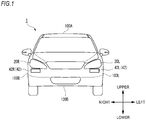
- FIG. 1 shows a front view of the vehicle 1 on which the illumination device 4 (see FIG. 2 ) according to the first embodiment is mounted.
- the vehicle 1 is an automobile capable of travelling in an automatic driving mode and includes the illumination device 4.
- the illumination device 4 includes an illumination unit 42 and an illumination control unit 43 (see FIG. 2 ).
- the illumination unit 42 is configured to display stop warning information forewarning the stop of the vehicle 1 toward the front of the vehicle 1 and has a left illumination unit 42L and a right illumination unit 42R.
- the left illumination unit 42L is disposed in the vicinity of a left headlamp 20L
- the right illumination unit 42R is disposed in the vicinity of a right headlamp 20R.
- Each of the left illumination unit 42L and the right illumination unit 42R is, for example, a laser scanning device that includes a laser light source and an optical deflection device for deflecting laser light emitted from the laser light source.
- the optical deflection device is, for example, a movable mirror such as an MEMS (Micro Electro Mechanical Systems) mirror or a galvanometer mirror.
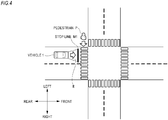
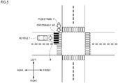
- the illumination unit 42 scans laser light to draw stop warning information (e.g., a stop line M1 shown in FIG. 4 or a crosswalk M2 shown in FIG. 5 ) on a road surface in front of the vehicle 1.
- stop warning information e.g., a stop line M1 shown in FIG. 4 or a crosswalk M2 shown in FIG. 5
- the left illumination unit 42L and the right illumination unit 42R are disposed in the vicinity of the left headlamp 20L and the right headlamp 20R, respectively.
- the number and arrangement of the illumination unit 42 are not particularly limited, so long as the illumination unit 42 (the left illumination unit 42L and the right illumination unit 42R) are configured to be able to display the stop warning information toward the front of the vehicle 1.
- the left illumination unit 42L may be disposed in the left headlamp 20L
- the right illumination unit 42R may be disposed in the right headlamp 20R.
- the left illumination unit 42L may be disposed on a left surface 100L
- the right illumination unit 42R may be disposed on a right surface 100R.
- the single illumination unit 42 may be disposed on a vehicle body roof 100A of the vehicle 1 or on a rear surface 100B facing a road surface.
- FIG. 2 shows a block diagram of the vehicle system 2.
- the vehicle system 2 includes a vehicle control unit 3, the illumination device 4, a sensor 5, a camera 6, a radar 7, a HMI (Human Machine Interface) 8, a GPS (Global Positioning System) 9, a wireless communication unit 10, and a map information storage unit 11.
- the vehicle system 2 further includes a steering actuator 12, a steering device 13, a brake actuator 14, a brake device 15, an accelerator actuator 16, and an accelerator device 17.
- the vehicle control unit 3 is configured to control the travelling of the vehicle 1.
- the vehicle control unit 3 is configured by, for example, an electronic control unit (ECU: Electronic Control Unit).
- the electronic control unit includes a microcontroller having a processor and a memory, and other electronic circuits (e.g., transistors, etc.).
- the processor is, for example, a CPU (Central Processing Unit), an MPU (Micro Processing Unit) and/or a GPU (Graphics Processing Unit).
- the memory includes a ROM (Read Only Memory) in which various vehicle control programs (e.g., an artificial intelligence (AI) program for automatic driving, etc.) are stored, and a RAM (Random Access Memory) in which various vehicle control data are temporarily stored.
- the processor is configured to develop, on the RAM, a program designated from the various vehicle control programs stored in the ROM and execute various processes in cooperation with the RAM
- the illumination device 4 is configured to display the stop warning information toward the front of the vehicle 1, and includes the illumination unit 42 and the illumination control unit 43.
- the illumination control unit 43 is configured by an electronic control unit (ECU) and controls the illumination unit 42 so that the stop warning information is displayed toward the front of the vehicle 1.
- ECU electronic control unit
- the vehicle control unit 3 when it is determined that the vehicle 1 should be stopped, the vehicle control unit 3 generates an instruction signal for instructing to display the stop warning information and transmits the instruction signal to the illumination control unit 43.
- the illumination control unit 43 displays the stop warning information in front of the vehicle 1 by driving and controlling the illumination unit 42 based on the received instruction signal. That is, the illumination device 4 displays the stop warning information in front of the vehicle 1 based on the instruction signal.
- the illumination control unit 43 is configured by an electronic control unit (ECU).
- the illumination control unit 43 is configured to set an illumination state (turn on/off, illumination color, luminous intensity, light emitting area or blinking cycle, etc.) of the illumination unit 42 to a predetermined illumination state in accordance with information relating to the automatic driving of the vehicle 1.
- the electronic control unit is electrically connected to a power supply (not shown) and includes a microcontroller having a processor such as a CPU or an MPU and a memory such as a ROM and a RAM, and other electronic circuits (e.g., a drive circuit such as an LED driver).
- the vehicle control unit 3 and the illumination control unit 43 are provided as a separate component.
- the vehicle control unit 3 and the illumination control unit 43 may be integrally configured. That is, the illumination control unit 43 and the vehicle control unit 3 may be configured by a single electronic control unit.
- the sensor 5 includes an acceleration sensor, a speed sensor, a gyro sensor, and the like.
- the sensor 5 is configured to detect a travelling condition of the vehicle 1 and output the travelling condition information to the vehicle control unit 3.
- the sensor 5 may further include a seating sensor configured to detect whether a driver is sitting on a driver's seat, a face orientation sensor configured to detect a direction of a driver's face, an external weather sensor configured to detect external weather condition, a human sensor configured to detect whether a person is inside a vehicle, and the like.
- the sensor 5 may include an illuminance sensor configured to detect illuminance of the surrounding environment of the vehicle 1.
- the camera 6 is, for example, a camera including an imaging device such as a CCD (Charge-Coupled Device) and CMOS (complementary MOS).
- the radar 7 is a millimeter wave radar, a microwave radar, a laser radar, or the like.
- the camera 6 and the radar 7 are configured to detect the surrounding environment (other vehicles, pedestrians, road shapes, traffic signs, obstacles, etc.) of the vehicle 1 and output the surrounding environment information to the vehicle control unit 3.
- the HMI 8 includes an input unit configured to receive an input operation from a driver and an output unit configured to output the travelling information and the like to the driver.
- the input unit includes a steering wheel, an accelerator pedal, a brake pedal, a driving mode changeover switch for switching the driving mode of the vehicle 1, and the like.
- the output unit is a display for displaying various travelling information.
- the GPS 9 is configured to acquire current position information of the vehicle 1 and output the acquired current position information to the vehicle control unit 3.
- the wireless communication unit 10 is configured to receive information (e.g., travelling information) relating to other vehicle around the vehicle 1 from other vehicle and transmit information (e.g., travelling information) relating to the vehicle 1 to other vehicle (inter-vehicle communication). Further, the wireless communication unit 10 is configured to receive infrastructure information from infrastructure equipment such as traffic lights and sign lamps and transmit the travelling information of the vehicle 1 to the infrastructure equipment (road-to-vehicle communication).
- the map information storage unit 11 is an external storage device such as a hard disk drive in which map information is stored. The map information storage unit 11 is configured to output the map information to the vehicle control unit 3.
- the vehicle control unit 3 automatically generates at least one of a steering control signal, an accelerator control signal and a brake control signal based on the travelling condition information, the surrounding environment information, the current position information, the map information, and the like.
- the steering actuator 12 is configured to receive the steering control signal from the vehicle control unit 3 and control the steering device 13 based on the received steering control signal.
- the brake actuator 14 is configured to receive the brake control signal from the vehicle control unit 3 and control the brake device 15 based on the received brake control signal.
- the accelerator actuator 16 is configured to receive the accelerator control signal from the vehicle control unit 3 and control the accelerator device 17 based on the received accelerator control signal.
- the travelling of the vehicle 1 is automatically controlled by the vehicle system 2.
- the vehicle control unit 3 when the vehicle 1 travels in a manual driving mode, the vehicle control unit 3 generates a steering control signal, an accelerator control signal and a brake control signal in accordance with a manual operation of a driver on the brake pedal and the steering wheel.
- the steering control signal, the accelerator control signal and the brake control signal are generated by the manual operation of the driver, so that the travelling of the vehicle 1 is controlled by the driver.
- the driving mode includes an automatic driving mode and a manual driving mode.
- the automatic driving mode includes a fully automatic driving mode, an advanced driving support mode, and a driving support mode.
- the vehicle system 2 automatically performs all of the travelling controls of the steering control, the brake control and the accelerator control, and the driver is not in a state where it is possible to drive the vehicle 1.
- the vehicle system 2 automatically performs all of the travelling controls of the steering control, the brake control and the accelerator control, and the driver does not drive the vehicle 1 although the driver is in a state where it is possible to drive the vehicle 1.
- the vehicle system 2 In the driving support mode, the vehicle system 2 automatically performs a part of the travelling controls of the steering control, the brake control and the accelerator control, and the driver drives the vehicle 1 under the driving support of the vehicle system 2.
- the vehicle system 2 In the manual driving mode, the vehicle system 2 does not automatically perform the travelling controls, and the driver drives the vehicle 1 without the driving support of the vehicle system 2.
- the driving mode of the vehicle 1 may be switched by operating a driving mode changeover switch.
- the vehicle control unit 3 switches the driving mode of the vehicle 1 among four driving modes (the fully automatic driving mode, the advanced driving support mode, the driving support mode, and the manual driving mode) in accordance with the operation of the driver on the driving mode changeover switch.
- the driving mode of the vehicle 1 may be automatically switched based on the information relating to a travel-allowed section where the travelling of an automatic driving vehicle is allowed or a travel-prohibited section where the travelling of the automatic driving vehicle is prohibited or the information relating to the external weather condition. In this case, the vehicle control unit 3 switches the driving mode of the vehicle 1 based on such information.
- the driving mode of the vehicle 1 may be automatically switched by using a seating sensor, a face orientation sensor, or the like. In this case, the vehicle control unit 3 switches the driving mode of the vehicle 1 based on the output signal from the seating sensor or the face orientation sensor.
- the vehicle control unit 3 determines whether the driving mode of the vehicle 1 is the automatic driving mode (Step S10). When it is determined that the driving mode of the vehicle 1 is the automatic driving mode (YES in Step S10), the vehicle control unit 3 determines whether to stop the vehicle 1 (Step S11). On the other hand, when it is determined that the driving mode of the vehicle 1 is not the automatic driving mode (that is, when it is determined that the driving mode of the vehicle 1 is the manual driving mode) (NO in Step S10), the vehicle control unit 3 waits until the driving mode of the vehicle 1 becomes the automatic driving mode.
- the vehicle control unit 3 may determine whether to stop the vehicle 1 based on the surrounding environment information obtained from the camera 6 or the radar 7. For example, when it is determined from the surrounding environment information that a front obstacle such as a broken car or a stop sign exists in front of the vehicle 1, the vehicle control unit 3 may determine that the vehicle 1 should be stopped. Further, when it is determined from the surrounding environment information that the color of a traffic light in front of the vehicle 1 is red, the vehicle control unit 3 may determine that the vehicle 1 should be stopped. Further, when it is determined from the surrounding environment information that a pedestrian exists in the vicinity of a crosswalk, the vehicle control unit 3 may determine that the vehicle 1 should be stopped.
- the vehicle control unit 3 may determine that the vehicle 1 should be stopped, irrespective of the present or absence of a pedestrian.
- Step S11 When it is determined that the vehicle 1 should be stopped (YES in Step S11), the vehicle control unit 3 generates an instruction signal for instructing to display the stop warning information and transmits the instruction signal to the illumination control unit 43. Then, the illumination control unit 43 drives and controls the illumination unit 42 based on the received instruction signal. As a result, the stop warning information formed by laser scanning is displayed on a road surface in front of the vehicle 1 (Step S12). Then, the vehicle control unit 3 transmits a brake control signal to the brake actuator 14. The brake actuator 14 stops the vehicle 1 by controlling the brake device 15 based on the received brake control signal (Step S13). On the other hand, when the vehicle control unit 3 determines that the vehicle 1 should not be stopped (NO in Step S11), the process returns to Step S10. In this manner, a series of process is ended. This process may be repeatedly executed at a predetermined cycle.
- Step S10 the vehicle control unit 3 determines whether the driving mode of the vehicle 1 is the automatic driving mode.
- the vehicle control unit 3 may determine whether the driving mode of the vehicle 1 is the automatic driving mode excluding the driving support mode. That is, since a pedestrian existing in front of the vehicle 1 cannot confirm the state and sign of a driver in the case where the vehicle 1 is travelling in the fully automatic driving mode or the advanced driving support mode, it is difficult to judge whether the vehicle 1 is stopped. Therefore, when the driving mode is the fully automatic driving mode or the advanced driving support mode, the stop warning information is especially beneficial for pedestrians.
- Step S12 when the vehicle control unit 3 determines that the vehicle 1 should be stopped, the stop warning information is displayed on a road surface in front of the vehicle 1.
- the stop warning information may not be displayed depending on a situation (in other words, the vehicle control unit 3 may not generate the instruction signal). For example, in a situation where the vehicle 1 is stopped at a travelling section for which entry of a pedestrian is prohibited or in a situation where the vehicle 1 is stopped at a crosswalk where a pedestrian does not exist obviously in the vicinity, the stop warning information may not be displayed.
- FIG. 4 shows the stop line M1 as an example of the stop warning information displayed on the road surface R in front of the vehicle 1.
- FIG. 5 shows the crosswalk M2 as another example of the stop warning information displayed on the road surface R in front of the vehicle 1.
- the illumination unit 42 (the left illumination unit 42L and the right illumination unit 42R) is configured by a laser light source for emitting laser light and an optical deflection device for deflecting the laser light.
- the optical deflection device deflects the laser light and scans the laser light on the road surface R in front of the vehicle 1. In this way, the stop line M1 or the crosswalk M2 is displayed on the road surface R in front of the vehicle 1 by the scanning of the laser light. Meanwhile, it is preferable that the color of the laser light is green.
- the illumination device 4 capable of displaying, toward the front of the vehicle 1, the stop warning information forewarning the stop of the vehicle 1 travelling in the automatic driving mode.
- a pedestrian P existing in front of the vehicle 1 can grasp in advance that the vehicle 1 is stopped by looking at the stop warning information (the stop line M1 or the crosswalk M2) displayed on the road surface R, so that the pedestrian P can safely cross the crosswalk or the like.
- an occupant of the vehicle 1 in particular, an occupant sitting on a driver's seat
- the stop line M1 and the crosswalk M2 are exemplified as an example of the stop warning information.
- other figures or character information may be displayed on the road surface R.
- the illumination unit 42 (the left illumination unit 42L and the right illumination unit 42R) is configured to display the stop warning information (the stop line M1 and the crosswalk M2) formed by the scanning of the laser light on the road surface R.
- the illumination unit 42 (the left illumination unit 42L and the right illumination unit 42R) is configured to irradiate light toward the front of the vehicle 1, and the illumination control unit 43 is configured to set the illumination state (the turn on/off, the illumination color, the light emitting area, the blinking cycle and the luminous intensity, etc.) of the illumination unit 42 to a predetermined illumination state.
- the illumination unit 42 includes one or more light emitting elements such as an LED (Light Emitting Diode) or laser.
- the illumination control unit 43 sets the illumination state of the illumination unit 42 to a predetermined illumination state based on the instruction signal received from the vehicle control unit 3. Specifically, the illumination control unit 43 may be configured to turn on or turn off the illumination unit 42 based on the instruction signal.
- the illumination control unit 43 may turn on the illumination unit 42 based on the instruction signal.
- the illumination control unit 43 may turn off the illumination unit 42 based on the instruction signal.
- the illumination control unit 43 may set the illumination color of the illumination unit 42 to a predetermined illumination color (e.g., white, green, blue, etc.) based on the instruction signal.
- the illumination control unit 43 may set the light emitting area of the illumination unit 42 to a predetermined light emitting area (e.g., the half of the volume of the illumination unit 42 may be set as the light emitting area) based on the instruction signal.
- the illumination control unit 43 may set the blinking cycle of the illumination unit 42 to a predetermined blinking cycle T based on the instruction signal. For example, when the illumination unit 42 is not blinking in the initial state, the illumination control unit 43 may cause the illumination unit 42 to blink based on the instruction signal. Furthermore, the illumination control unit 43 may set the luminous intensity of the illumination unit 42 to a predetermined luminous intensity I. As a result, the change in the illumination state of the illumination unit 42 of the illumination unit 42 is displayed toward the front of the vehicle 1.
- the pedestrian P existing in front of the vehicle 1 can grasp in advance that the vehicle 1 is stopped by looking at the illumination state of the illumination unit 42.
- the change in the illumination state of the illumination unit 42 the changes in the turn on/off, the light emitting area, the illumination color, the blinking cycle and the luminous intensity of the illumination unit 42 have been described, respectively.
- the change in the illumination state is not limited to these.
- Various changes in the illumination state can be applied, so long as the illumination state of the illumination unit 42 can be changed in accordance with the driving mode of the vehicle 1.
- the illumination state of the illumination unit 42 may be changed by combining the turn on/off, the light emitting area, the illumination color, the blinking cycle and the luminous intensity of the illumination unit 42.
- the illumination control unit 43 may predict the lifetime of the illumination unit 42 based on a current value and a voltage value of a lighting control circuit constituting the illumination control unit 43 and the temperature and humidity inside the illumination unit 42, and change the illumination state (the turn on/off, the light emitting area, the illumination color, the blinking cycle and the luminous intensity) of the illumination unit based on the predicted lifetime of the illumination unit 42. For example, when it is predicted that the predicted lifetime of the illumination unit 42 is short (e.g., the predicted lifetime is 100 hours or less), the illumination control unit 43 may set the illumination color of the illumination unit 42 to a first illumination color (e.g., red).
- a first illumination color e.g., red
- the illumination control unit 43 may set the illumination color of the illumination unit 42 to a second illumination color (e.g., yellow). Furthermore, when it is predicted that the predicted lifetime of the illumination unit 42 is long (e.g., the predicted lifetime is 500 hours or more), the illumination control unit 43 may set the illumination color of the illumination unit 42 to a third illumination color (e.g., green). Meanwhile, instead of the illumination control unit 43, the vehicle control unit 3 may predict the lifetime of the illumination unit 42. In this case, the illumination control unit 43 may receive data indicating the predicted lifetime of the illumination unit 42 from the vehicle control unit 3 and then change the illumination state of the illumination unit 42 based on the received data.
- a second illumination color e.g., yellow
- the illumination control unit 43 may set the illumination color of the illumination unit 42 to a third illumination color (e.g., green).
- the vehicle control unit 3 may predict the lifetime of the illumination unit 42. In this case, the illumination control unit 43 may receive data indicating the predicted lifetime of the illumination unit 42 from the vehicle control unit 3 and then change
- a temperature sensor configured to measure the internal temperature of the illumination unit 42 and a humidity sensor configured to measure the internal humidity of the illumination unit 42 may be provided inside the illumination unit 42.
- a lifetime prediction formula indicating the relationship between a use time t of the light emitting element and a luminance L of the light emitting element may be stored in a memory of the illumination control unit 43.
- the illumination control unit 43 may determine the predicted lifetime of the illumination unit 42 based on the lifetime prediction formula and the current luminance L of the light emitting element.
- the lifetime prediction formula stored in the memory may be acquired from a server arranged on a communication network via the wireless communication unit 10. In this case, the illumination control unit 43 may periodically acquire the updated lifetime prediction formula from the server arranged on the communication network.
- the illumination control unit 43 may acquire the lifetime prediction formula based on the indoor temperature of 50 degrees from the server and then determine the predicted lifetime of the illumination unit 42 based on the acquired lifetime prediction formula based on the indoor temperature of 50 degrees and the current luminance L of the light emitting element. In this way, a suitable lifetime prediction formula can be acquired via the communication network, so that the lifetime of the illumination unit 42 can be predicted more accurately.
- the illumination control unit 43 changes the illumination state of the illumination unit 42 in accordance with the predicted lifetime of the illumination unit 42, and thus, it is possible to present the information relating to the lifetime of the illumination unit 42 toward the outside of the vehicle. In this manner, pedestrians or the like existing outside the vehicle can grasp the lifetime of the illumination unit 42 by visually recognizing the illumination state of the illumination unit 42.
- the illumination control unit 43 may change the illumination state (the turn on/off, the light emitting area, the illumination color, the blinking cycle and the luminous intensity) of the illumination unit 42 based on the current condition of a driver.
- the vehicle control unit 3 may acquire the captured image of the driver from the camera 6 and then determine the current condition of the driver based on the acquired captured image and a face recognition algorithm.
- the vehicle control unit 3 when it is determined that the driver cannot drive (e.g., when it is determined that the driver is dozing), the vehicle control unit 3 generates a predetermined illumination control signal and then transmits the predetermined illumination control signal to the illumination control unit 43.
- the illumination control unit 43 may set the illumination color of the illumination unit 42 to a predetermined illumination color (e.g., red) based on the predetermined illumination control signal. In this manner, it is possible to present the information relating to the current condition of the driver toward the outside of the vehicle.
- a predetermined illumination color e.g., red
- a speaker may output the stop warning guidance of the vehicle 1.
- the speaker may be installed at a predetermined position of the vehicle so as to output the stop warning guidance of the vehicle 1 toward the outside of the vehicle.
- a speaker control unit (not shown) configured to control the speaker may store the data relating to the stop warning guidance of the vehicle 1.
- the speaker control unit receives a signal indicating the stop of the vehicle 1 from the vehicle control unit 3 and then outputs the stop voice guidance to the speaker in accordance with the received signal.
- FIG. 6 shows a front view of a vehicle 1A on which an illumination unit 42A according to the second modification is mounted.
- the illumination unit 42A displays character information M3 ("THE CAR WILL STOP SOON") as the stop warning information on a front window 120F of the vehicle 1A.
- the illumination unit 42A is a projection device such as a projector for projecting the character information M3 on the front window 120F and is arranged at a predetermined position on the front window 120F.
- the illumination control unit 43 drives and controls the illumination unit 42A based on the instruction signal received from the vehicle control unit 3. As a result, the stop warning information projected from the illumination unit 42A is displayed on the front window 120F of the vehicle 1.
- the pedestrian P existing in front of the vehicle 1A can grasp in advance that the vehicle 1A is stopped by looking at the stop warning information.
- the illumination unit 42A is disposed on the front window 120F.
- the illumination unit 42A may be formed integrally with the front window 120F.
- the front window 120F itself functions as a display device for displaying the character information M3.
- another illumination unit (not shown) may be disposed on side windows 120L, 120R, respectively.
- another illumination unit (not shown) may be disposed on the left surface 100L and the right surface 100R of the vehicle 1A, respectively.
- the character information M3 shown in FIG. 6 is merely an example, and other character information and graphic information may be displayed on the front window 120F as the stop warning information.
- the illumination units 42, 42A for displaying the stop warning information have been described, respectively.
- the vehicle may include both the illumination unit 42 and the illumination unit 42A.
- FIG. 7A shows a front view of a vehicle 1B
- FIG. 7B shows a left side view of the vehicle 1B
- the vehicle 1B is a vehicle capable of travelling in an automatic driving mode and includes the illumination device 4B.
- the illumination device 4B includes an illumination unit 42B (first illumination unit) and the illumination control unit 43 (see FIG. 8 ).
- the illumination unit 42B is disposed on the vehicle body roof 100A of the vehicle 1B and is configured to irradiate a light pattern toward the outside of the vehicle 1B.
- the illumination unit 42B (first illumination unit) is, for example, a laser scanning device that includes a laser light source and an optical deflection device for deflecting laser light emitted from the laser light source.
- the optical deflection device is, for example, a movable mirror such as an MEMS (Micro Electro Mechanical Systems) mirror or a galvanometer mirror.
- the illumination unit 42B scans laser light to irradiate a light pattern (e.g., a ring-shaped light pattern M1 or a linear light pattern M2 shown in FIG. 9 ) toward an object such as a pedestrian.
- a light pattern e.g., a ring-shaped light pattern M1 or a linear light pattern M2 shown in FIG. 9
- the illumination unit 42B scans the laser light to draw a light pattern on a road surface around the object.
- the single illumination unit 42B is disposed on the vehicle body roof 100A.
- the number, arrangement and shape or the like of the illumination unit 42B are not particularly limited, so long as the illumination unit 42B can irradiate a light pattern toward an object existing in an arbitrary direction with respect to the vehicle 1B.
- each of two illumination units 42B among four illumination units 42B may be disposed in the left headlamp 20L and the right headlamp 20R, and each of the remaining two illumination units 42B may be disposed in a left rear combination lamp 30L and a right rear combination lamp 30R.
- the illumination unit 42B may be arranged so as to surround a side surface 100X of the vehicle 1B.
- FIG. 8 shows a block diagram of the vehicle system 2B.
- the vehicle system 2B includes the vehicle control unit 3, the illumination device 4B, the sensor 5, the camera 6, the radar 7, the HMI (Human Machine Interface) 8, the GPS (Global Positioning System) 9, the wireless communication unit 10 (first wireless communication unit), and the map information storage unit 11.
- the vehicle system 2B further includes the steering actuator 12, the steering device 13, the brake actuator 14, the brake device 15, the accelerator actuator 16, and the accelerator device 17.
- the illumination device 4B is configured to irradiate laser light (in particular, a light pattern having a ring shape or a linear shape) toward the outside (in particular, an object such as a pedestrian or an emergency vehicle) of the vehicle 1B, and includes the illumination unit 42B and an illumination control unit 43B.
- the illumination control unit 43B is configured by an electronic control unit (ECU).
- the illumination control unit 43B is configured to control the illumination unit 42B so that the laser light is irradiated toward the object, based on the position information of the object.
- FIG. 9 shows a state in which the illumination unit 42B irradiates a light pattern toward a pedestrian.
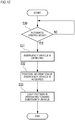
- FIG. 10 is a flowchart showing a process of irradiating a light pattern toward a pedestrian.
- the vehicle control unit 3 determines whether the driving mode of the vehicle 1B is the automatic driving mode (Step S20). When the vehicle control unit 3 determines that the driving mode of the vehicle 1B is the automatic driving mode (YES in Step S20), the process proceeds to Step S21. On the other hand, when it is determined that the driving mode of the vehicle 1B is not the automatic driving mode (that is, when it is determined that the driving mode of the vehicle 1B is the manual driving mode) (NO in Step S20), the vehicle control unit 3 waits until the driving mode of the vehicle 1B becomes the automatic driving mode.
- Step S21 the vehicle control unit 3 (detection unit) detects a pedestrian P1 (see FIG. 9 ) by using the camera 6 and/or the radar 7.
- the vehicle control unit 3 detects the pedestrian P1 based on the surrounding environment information acquired from the camera 6 and/or the radar 7.
- Step S22 the vehicle control unit 3 (position information acquisition unit) acquires position information of the pedestrian P1 based on the acquired surrounding environment information. Then, the vehicle control unit 3 generates an instruction signal for instructing to irradiate a light pattern and transmits the instruction signal and the position information of the pedestrian P1 to the illumination control unit 43B. Then, the illumination control unit 43B drives and controls the illumination unit 42B in accordance with the received instruction signal. Furthermore, the illumination control unit 43B controls the illumination unit 42B so that a light pattern is irradiated toward the pedestrian PI, based on the received position information. In particular, the optical deflection device of the illumination unit 42 scans the laser light emitted from the laser light source on a road surface around the pedestrian P1. As a result, the ring-shaped light pattern M1 (see FIG. 9 ) formed by the laser scanning is irradiated toward the pedestrian P1. In particular, the light pattern M1 is drawn on a road surface around the pedestrian P1.
- the linear light pattern M2 may be irradiated to a pedestrian P2 from the illumination unit 42B of a vehicle 1C having the same configuration as that of the vehicle 1B.
- the linear light pattern M2 is drawn on a road surface in front of the pedestrian P2.
- a light pattern having a ring shape or linear shape may be irradiated from the illumination unit 42B or a light pattern having other shapes may be irradiated from the illumination unit 42B.
- the laser light may be merely irradiated to a pedestrian.
- the illumination device 4B which can present, toward a pedestrian, the fact that the vehicle 1B capable of travelling in the automatic driving mode is recognizing the pedestrian.
- the pedestrian can grasp that the vehicle 1B is recognizing the pedestrian by looking at the ring-shaped light pattern or the linear light pattern irradiated from the illumination unit 42B, so that the pedestrian can be relieved.
- a pedestrian trying to cross a crosswalk or the like can grasp that the vehicle 1B is recognizing the pedestrian by looking at the light pattern irradiated from the illumination unit 42B, so that the pedestrian can safely cross the crosswalk or the like.
- Step S20 the vehicle control unit 3 determines whether the driving mode of the vehicle 1B is the automatic driving mode.
- the vehicle control unit 3 may determine whether the driving mode of the vehicle 1B is the automatic driving mode excluding the driving support mode. That is, since a pedestrian cannot confirm the state and sign of a driver in the case where the vehicle 1B is travelling in the fully automatic driving mode or the advanced driving support mode, it is difficult to judge whether the vehicle 1B recognizes the pedestrian. Therefore, when the driving mode is the fully automatic driving mode or the advanced driving support mode, it is especially beneficial to irradiate a light pattern toward a pedestrian. Further, in this process, Step S20 may be omitted.
- Steps S21 to S23 may be executed.
- this process may be executed by a driver of the vehicle 1B performing a predetermined operation (such as an operation of pressing a predetermined switch).
- the vehicle control unit 3 functions as a detecting unit for detecting the pedestrian P1 and a position information acquisition unit for acquiring position information of the pedestrian P1.
- the camera 6 and/or the radar 7 may function as the detecting unit for detecting the pedestrian P1 and/or the position information acquisition unit for acquiring position information of the pedestrian P1.
- the vehicle control unit 3 transmits the instruction signal and the position information to the illumination control unit 43B.
- the vehicle control unit 3 may transmit only the position information to the illumination control unit 43B.
- the vehicle control unit 3 may detect the pedestrian P1 and acquire position information of the pedestrian P1 by pedestrian-to-vehicle communication via the wireless communication unit 10, instead of the camera 6 and/or the radar 7.
- the wireless communication unit 10 receives position information or the like of the pedestrian P1 from a mobile terminal such as a mobile phone, a smart phone, a tablet or a wearable device carried by the pedestrian and provides the position information or the like to the vehicle control unit 3.
- the vehicle control unit 3 may detect the pedestrian P1 and acquire position information of the pedestrian P1 by road-to-vehicle communication via the wireless communication unit 10.
- infrastructure equipment existing in the vicinity of the pedestrian P1 includes an image acquisition means such as a camera capable of acquiring an image of the pedestrian P1.
- the infrastructure equipment detects the presence of the pedestrian P1 by the image acquisition means and acquires position information of the pedestrian P1.
- the wireless communication unit 10 receives the position information or the like of the pedestrian P1 from the infrastructure equipment and provides the position information or the like to the vehicle control unit 3.
- the illumination unit 42B irradiates a light pattern toward the pedestrian P1 existing in the vicinity of an intersection.
- the position of the pedestrian P1 is not particularly limited.
- the illumination unit 42B may irradiate a light pattern toward a pedestrian existing at a position distant from an intersection.
- the illumination unit 42B may irradiate a light pattern toward a plurality of pedestrians.
- the object to which a light pattern is irradiated is not limited to a pedestrian, but may be a person riding a bicycle, a person riding on a senior car (Senior Car (registered trademark)) or a person walking on a sidewalk.
- FIG. 11 shows a state in which the illumination unit 42B irradiates a light pattern toward an emergency vehicle 60.
- FIG. 12 is a flowchart showing a process of irradiating a light pattern toward the emergency vehicle 60.
- Step S30 the vehicle control unit 3 determines whether the driving mode of the vehicle 1B is the automatic driving mode (Step S30). Since Step S30 corresponds to Step S20 shown in FIG. 10 , the description thereof will be omitted here.
- Step S31 the vehicle control unit 3 (detection unit) detects the emergency vehicle 60 (see FIG. 11 ) by using the camera 6 and/or the radar 7.
- the vehicle control unit 3 detects the emergency vehicle 60 based on the surrounding environment information acquired from the camera 6 and/or the radar 7.
- Step S32 the vehicle control unit 3 (position information acquisition unit) acquires position information of the emergency vehicle 60 based on the acquired surrounding environment information. Then, the vehicle control unit 3 generates an instruction signal for instructing to irradiate a light pattern and transmits the instruction signal and the position information of the emergency vehicle 60 to the illumination control unit 43B. Then, the illumination control unit 43B drives and controls the illumination unit 42B in accordance with the received instruction signal. Further, the illumination control unit 43B controls the illumination unit 42B so that a light pattern is irradiated toward the emergency vehicle 60, based on the received position information. As a result, a ring-shaped light pattern M3 (see FIG.
- the light pattern M3 is drawn on a road surface around the emergency vehicle 60. Meanwhile, instead of the ring-shaped light pattern, a light pattern having other shapes may be irradiated.
- the illumination device 4B which can present, toward the emergency vehicle 60, the fact that the vehicle 1B capable of travelling in the automatic driving mode is recognizing the emergency vehicle 60.
- a driver of the emergency vehicle 60 can grasp that the vehicle 1B is recognizing the emergency vehicle 60 by looking at the ring-shaped light pattern irradiated from the illumination unit 42B, so that the driver of the emergency vehicle 60 can safely overtake the vehicle 1B.
- the vehicle control unit 3 may detect the emergency vehicle 60 and acquire position information of the emergency vehicle 60 by vehicle-to-vehicle communication via the wireless communication unit 10.
- the wireless communication unit 10 receives the position information or the like of the emergency vehicle 60 from a wireless communication unit of the emergency vehicle 60 and provides the position information or the like to the vehicle control unit 3.
- the vehicle control unit 3 may detect the emergency vehicle 60 and acquire position information of the emergency vehicle 60 by using a sound sensor.
- the system for vehicle 300 includes the vehicle system 2C and the mobile terminal 50.
- the vehicle system 2C has the same configuration as the vehicle system 2B shown in FIG. 8 except for a vehicle illumination device 4C.
- the description of the components having the same reference numerals as the components described above will be appropriately omitted.
- the vehicle illumination device 4C (hereinafter, simply referred to as the "illumination device 4C") includes an illumination control unit 43C, the illumination unit 42B, and an illumination unit 45 (second illumination unit).
- the illumination unit 45 (not shown) is disposed on the vehicle body roof 100A shown in FIGS. 7A and 7B and is configured to irradiate light toward the outside of the vehicle 1B and over the entire circumference of the vehicle 1B in the horizontal direction.
- the horizontal direction is a plane direction that includes a front-rear direction and a left-right direction and that is perpendicular to the vertical direction.
- the illumination unit 45 includes one or more light emitting elements such as an LED (Light Emitting Diode), for example. Meanwhile, the illumination unit 45 may be arranged so as to surround the side surface 100X of the vehicle 1B or may be formed integrally with the illumination unit 42B (e.g., the illumination unit 45 may be disposed in the illumination unit 42B).
- the illumination control unit 43C is configured by an electronic control unit (ECU).
- the illumination control unit 43C is configured to control the illumination unit 42B so that a light pattern is irradiated toward an object such as a pedestrian or an emergency vehicle. Further, the illumination control unit 43C is configured to control the illumination state (illumination color, blinking, etc.) of the illumination unit 45. In particular, the illumination control unit 43C is configured to control the illumination unit 45 so that the illumination state of the illumination unit 45 corresponds to an illumination state of a display unit 53 of the mobile terminal 50.
- ECU electronice control unit
- the mobile terminal 50 is, for example, a mobile phone, a smart phone, a tablet or a wearable device (e.g., Apple Watch or Google Glass (registered trademark)) and is carried by a pedestrian. Meanwhile, the mobile terminal 50 may be carried by a person riding a bicycle, a person riding on a senior car or a person walking on a sidewalk. In the following description, it is assumed that the mobile terminal 50 is carried by the pedestrian P1 shown in FIG. 9 .
- the mobile terminal 50 includes a wireless communication unit 51 (second wireless communication unit), a control unit 52, and the display unit 53.
- the wireless communication unit 51 is configured to perform wireless communication with the wireless communication unit 10 of the vehicle system 2C.
- the wireless communication unit 51 may directly communicate with the wireless communication unit 10 in an ad hoc mode or may communicate with the wireless communication unit 10 via an access point.
- the display unit 53 is, for example, a display device for displaying information and is configured to irradiate light.
- the control unit 52 is configured to control an illumination state (illumination color, blinking, etc.) of the display unit 53.
- the control unit 52 is configured to control the display unit 53 so that the illumination state of the display unit 53 corresponds to the illumination state of the illumination unit 45.
- the vehicle control unit 3 detects the pedestrian P1 shown in FIG. 9 and acquires position information of the pedestrian P1. Then, the vehicle control unit 3 transmits a communication request signal to the pedestrian P1 via the wireless communication unit 10 in order to establish wireless communication (ad hoc communication) between the vehicle system 2C and the mobile terminal 50 of the pedestrian P1. Then, the wireless communication unit 51 of the mobile terminal 50 receives the communication request signal, and then, the control unit 52 performs a predetermined process. Then, the wireless communication unit 51 transmits a response signal to the communication request signal to the wireless communication unit 10. In this way, the wireless communication between the vehicle system 2A and the mobile terminal 50 is established.
- the vehicle control unit 3 generates an illumination control signal including information relating to the illumination state of the illumination unit 45. Further, the wireless communication unit 10 transmits the illumination control signal to the wireless communication unit 51.
- the control unit 52 controls the display unit 53 so that the illumination state of the display unit 53 corresponds to the illumination state of the illumination unit 45, based on the received illumination control signal. For example, the control unit 52 controls the display unit 53 so that the illumination color of the display unit 53 is the same as the illumination color of the illumination unit 45. Further, the control unit 52 controls the display unit 53 so that the display unit 53 blinks in synchronization with the illumination unit 45.
- the control unit 52 After the wireless communication between the vehicle system 2C and the mobile terminal 50 is established, the control unit 52 generates an illumination control signal including information relating to the illumination state of the display unit 53. Further, the wireless communication unit 51 transmits the illumination control signal to the wireless communication unit 10. When the wireless communication unit 10 receives the illumination control signal from the wireless communication unit 51, the received illumination control signal is transmitted to the illumination control unit 43C. Then, the illumination control unit 43C controls the illumination unit 45 so that the illumination state of the illumination unit 45 corresponds to the illumination state of the display unit 53, based on the illumination control signal. For example, the illumination control unit 43C controls the illumination unit 45 so that the illumination color of the illumination unit 45 is the same as the illumination color of the display unit 53. Further, the illumination control unit 43C controls the illumination unit 45 so that the illumination unit 45 blinks in synchronization with the display unit 53.
- the pedestrian P1 carrying the mobile terminal 50 can graph that the vehicle 1 is recognizing the pedestrian P1 by looking at not only the ring-shaped light pattern M1 irradiated from the illumination unit 42 but also the illumination state of the illumination unit 45 and the illumination state of the display unit 53 of the mobile terminal 50, so that the pedestrian P1 can safely cross a crosswalk or the like.
- the illumination state of the illumination unit 45 corresponds to the illumination state of the display unit 53 of the mobile terminal 50
- the pedestrian P1 can grasp that the vehicle 1B is recognizing the pedestrian P1.
- the illumination state (illumination color, synchronous blinking) of the light pattern M1 irradiated from the illumination unit 42B may correspond to the illumination state of the display unit 53 while the illumination unit 42B irradiates the light pattern M1 toward the pedestrian. That is, the illumination color of the light pattern M1 may be the same as the illumination color of the display unit 53, or the light pattern M1 may blink in synchronization with the display unit 53.
- control unit 52 controls the display unit 53 so that the illumination state of the display unit 53 corresponds to the illumination state of the illumination unit 45.
- control unit 52 may control a speaker (not shown) so that an alarm sound is outputted from the speaker.
- the control unit 52 may change the alarm sound outputted from the speaker so as to be synchronized with the blinking of the display unit 53.
- the system for vehicle 400 includes the vehicle system 2C and the emergency vehicle 60.
- the emergency vehicle 60 includes a wireless communication unit 61 (second wireless communication unit), a control unit 62, and a display unit 63.
- the wireless communication unit 61 is configured to perform wireless communication (ad hoc communication) with the wireless communication unit 10 of the vehicle system 2C.
- the wireless communication unit 61 may directly communicate with the wireless communication unit 10 in an ad hoc mode or may communicate with the wireless communication unit 10 via an access point.
- the display unit 63 is, for example, an indicator displayed toward a driver and is configured to irradiate light.
- the control unit 62 is configured to control the illumination state (illumination color, blinking, etc.) of the display unit 63.
- the control unit 62 controls the display unit 63 so that the illumination state of the display unit 63 corresponds to the illumination state of the illumination unit 45.
- the process of controlling the illumination state of the display unit 63 is substantially the same as the process of controlling the illumination state of the display unit 53 shown in FIG. 13 . That is, when the wireless communication unit 61 receives a lighting control signal from the wireless communication unit 10, the control unit 62 controls the display unit 63 so that the illumination state of the display unit 63 corresponds to the illumination state of the illumination unit 45, based on the received lighting control signal.
- the process of controlling the illumination state of the illumination unit 45 is substantially the same as the process of controlling the illumination state of the illumination unit 45 shown in FIG. 13 . That is, when the wireless communication unit 10 receives a lighting control signal from the wireless communication unit 61, the illumination control unit 43C controls the illumination unit 45 so that the illumination state of the illumination unit 45 corresponds to the illumination state of the display unit 63, based on the received lighting control signal.
- the driver of the emergency vehicle 60 can grasp that the vehicle 1 is recognizing the emergency vehicle 60 by looking at not only the light pattern M3 (see FIG. 11 ) irradiated from the illumination unit 42 but also the illumination state of the illumination unit 45 and the illumination state of the display unit 63 of the emergency vehicle 60, so that the driver can safely overtake the vehicle 1B.
- the illumination state of the illumination unit 45 corresponds to the illumination state of the display unit 63, the driver of the emergency vehicle 60 can grasp that the vehicle 1B is recognizing the emergency vehicle 60.
- the driving mode of the vehicle includes the fully automatic driving mode, the advanced driving support mode, the driving support mode, and the manual driving mode.
- the driving mode of the vehicle should not be limited to these four modes.
- the classification of the driving mode of the vehicle may be appropriately changed in accordance with the laws and regulations pertaining to the automatic driving in each country.
- the definitions of "the fully automatic driving mode,” “the advanced driving support mode,” and “the driving support mode” described in the description of these embodiments are merely examples, and these definitions may be appropriately changed in accordance with the laws and regulations pertaining to the automatic driving in each country.
- the illumination control unit may set the illumination state (the turn on/off, the light emitting area, the illumination color, the blinking cycle and the luminous intensity) of the illumination unit to a predetermined illumination state in accordance with the following information.
Landscapes
- Engineering & Computer Science (AREA)
- Mechanical Engineering (AREA)
- Physics & Mathematics (AREA)
- General Physics & Mathematics (AREA)
- Automation & Control Theory (AREA)
- Transportation (AREA)
- Lighting Device Outwards From Vehicle And Optical Signal (AREA)
Abstract
Description
- The present disclosure relates to a vehicle illumination device. In particular, the present disclosure relates to a vehicle illumination device provided in a vehicle capable of travelling in an automatic driving mode. Further, the present disclosure relates to a vehicle system including the vehicle illumination device, and a vehicle including the vehicle system.
- Currently, research on the automatic driving technique of automobiles has been actively conducted in each country, and each country is examining laws so as to enable a vehicle (hereinafter, a "vehicle" refer to an automobile) to travel in an automatic driving mode on public roads. Here, in the automatic driving mode, a vehicle system automatically controls the travelling of a vehicle. Specifically, in the automatic driving mode, the vehicle system performs at least one of a steering control (control of the vehicle in the travelling direction), a brake control and an accelerator control (control of the braking and acceleration/deceleration of the vehicle) based on various information obtained from a camera, a sensor, and a radar or the like. On the other hand, in a manual driving mode described below, a driver controls the travelling of a vehicle, as in most of conventional vehicles. Specifically, in the manual driving mode, the travelling of the vehicle is controlled according to an operation (steering operation, braking operation, accelerator operation) of a driver, and the vehicle system does not automatically perform the steering control, the brake control and the accelerator control. Meanwhile, the driving mode of the vehicle is not a concept existing only in some vehicles but a concept existing in all vehicles including conventional type vehicles having no automatic driving function. For example, the driving mode of the vehicle is classified according to a vehicle control method or the like.
- Thus, in the future, it is expected that vehicles (hereinafter, suitably referred to as "automatic driving vehicle") travelling in the automatic driving mode and vehicles (hereinafter, suitably referred to as "manual driving vehicle") travelling in the manual driving mode coexist on public roads. In particular, under the situation where many automatic driving vehicles travel on public roads, it is preferable that a pedestrian or the like in front of an automatic driving vehicle can grasp in advance that the automatic driving vehicle is stopped. Furthermore, it is preferable that the automatic driving vehicle is capable of presenting that it is recognizing a pedestrian or an emergency vehicle or the like (hereinafter, a pedestrian or the like).
- For example, when a pedestrian trying to cross a crosswalk is present in front of a manual driving vehicle, the pedestrian can judge whether the vehicle is stopped before the crosswalk by confirming the state and sign of the driver of the manual driving vehicle. On the other hand, in the case of the automatic driving vehicle (in particular, automatic driving vehicle that is travelling in the fully automatic driving mode without occupant), it is difficult for a pedestrian trying to cross a crosswalk to judge in advance whether the vehicle is stopped before the crosswalk.
- Further, in the case where a pedestrian trying to cross a crosswalk is present in front of an automatic driving vehicle, the pedestrian feels uneasy whether he can cross the crosswalk if he does not know that the automatic driving vehicle is recognizing him. Furthermore, a driver of an emergency vehicle (an ambulance, a fire truck, a patrol car, etc.) travelling behind an automatic driving vehicle feels uneasy whether to overtake the automatic driving vehicle if he does not know that the automatic driving vehicle is recognizing the emergency vehicle.
-
Patent Document 1 discloses an automatic follow-up travelling system in which a following vehicle travels so as to automatically follow a preceding vehicle. In the automatic follow-up travelling system, each of the preceding vehicle and the following vehicle has an illumination device, character information for preventing interruption of other vehicle between the preceding vehicle and the following vehicle is displayed on the illumination device of the preceding vehicle, and character information indicating the automatic follow-up travelling mode is displayed on the illumination device of the following vehicle. - Patent Document 1:
JP-A-S9-277887 - However,
Patent Document 1 does not discuss a vehicle illumination device or a vehicle system capable of displaying information forewarning the stop of an automatic driving vehicle toward the front of the vehicle. - Further,
Patent Document 1 does not discuss a vehicle illumination device or a vehicle system capable of presenting, to an object, the fact that an automatic driving vehicle is recognizing the object. - Accordingly, a first object of the present disclosure is to provide a vehicle illumination device which can display, toward a front of the own vehicle, stop warning information forewarning stop of the own vehicle travelling in the automatic driving mode.
- Further, a second object of the present disclosure is to provide a vehicle illumination device which can present, to an object, a fact that the vehicle capable of travelling in the automatic driving mode is recognizing the object.
- A vehicle illumination device according to a first aspect of the present disclosure is provided in a vehicle capable of travelling in an automatic driving mode and includes an illumination unit configured to display stop warning information forewarning stop of the vehicle toward a front of the vehicle, and an illumination control unit configured to control the illumination unit such that the stop warning information is displayed toward the front of the vehicle.
- According to the above configuration, it is possible to provide the vehicle illumination device capable of displaying the stop warning information forewarning the stop of the own vehicle travelling in the automatic driving mode toward the front of the own vehicle. In this manner, since a pedestrian existing in front of the own vehicle can grasp in advance that the own vehicle is stopped by looking at the stop warning information, the pedestrian can safely cross a crosswalk or the like.
- The illumination unit may be configured to display the stop warning information on a road surface in front of the vehicle.
- According to the above configuration, a pedestrian existing in front of the own vehicle can grasp in advance that the own vehicle is stopped by looking at the stop warning information displayed on the road surface in front of the own vehicle.
- The illumination unit may be configured to display the stop warning information on a front window of the vehicle.
- According to the above configuration, a pedestrian existing in front of the own vehicle can grasp in advance that the own vehicle is stopped by looking at the stop warning information displayed on the front window of the vehicle.
- The illumination unit may be configured to irradiate light toward the front of the vehicle, and the illumination control unit may be configured to set an illumination state of the illumination unit to a predetermined illumination state.
- According to the above configuration, a pedestrian existing in front of the own vehicle can grasp in advance that the own vehicle is stopped by looking at the illumination state of the illumination unit.
- Further, there is provided a vehicle system including the above vehicle illumination device and a vehicle control unit configured to control travelling of the vehicle. The vehicle control unit generates an instruction signal for instructing to display the stop warning information when it is determined that the vehicle should be stopped. The vehicle illumination device displays the stop warning information toward the front of the vehicle based on the instruction signal.
- According to the above configuration, it is possible to provide the vehicle system capable of displaying the stop warning information forewarning the stop of the own vehicle travelling in the automatic driving mode toward the front of the own vehicle.
- Further, there may be provided a vehicle including the above vehicle system.
- According to the above configuration, it is possible to provide the vehicle capable of displaying the stop warning information forewarning the stop of the own vehicle travelling in the automatic driving mode toward the front of the own vehicle.
- A vehicle illumination device according to a second aspect of the present disclosure is provided in a vehicle capable of travelling in an automatic driving mode and includes a first illumination unit configured to irradiate light toward an outside of the vehicle, and an illumination control unit configured to control the first illumination unit to irradiate the light to an object based on position information of the object.
- According to the above configuration, it is possible to provide the vehicle illumination device capable of presenting, to an object such as a pedestrian, a fact that the vehicle capable of travelling in the automatic driving mode is recognizing the object. In this manner, since an object such a pedestrian or an emergency vehicle can grasp that the vehicle is recognizing the object by looking at the light irradiated from the first illumination unit, the object can be relieved.
- The first illumination unit may be configured to irradiate a light pattern which has a ring shape or a linear shape toward the outside of the vehicle. The illumination control unit may be configured to control the first illumination unit to irradiate the light pattern toward the object based on the position information of the object.
- According to the above configuration, since an object such a pedestrian or an emergency vehicle can grasp that the vehicle is recognizing the object by looking at the light pattern which has a ring shape or a linear shape irradiated from the first illumination unit, the object can be relieved.
- The object may be a pedestrian or an emergency vehicle.
- According to the above configuration, since a pedestrian trying to cross a crosswalk or the like can grasp that the vehicle is recognizing the pedestrian by looking at the light irradiated from the first illumination unit, the pedestrian can safely cross the crosswalk or the like. Further, since an emergency vehicle trying to overtake the vehicle can grasp that the vehicle is recognizing the emergency vehicle by looking at the light irradiated from the first illumination unit, the emergency vehicle can safely overtake the vehicle.
- Further, there may be provided a vehicle system including a detection unit configured to detect an object, a position information acquisition unit configured to acquire position information of the object, and the above vehicle illumination device. The vehicle illumination device may be configured to irradiate light toward the object based on the position information.
- According to the above configuration, it is possible to provide the vehicle system capable of presenting, to an object such as a pedestrian, the fact that a vehicle capable of travelling in the automatic driving mode is recognizing the object.
- Further, there may be provided a vehicle including the vehicle system.
- According to the above configuration, it is possible to provide the vehicle capable of travelling in the automatic driving mode and presenting, to an object, the fact that the vehicle is recognizing the object.
- Further, there may be provided a system for vehicle including the above vehicle system and a mobile terminal. In the system of vehicle, the object is a pedestrian carrying the mobile terminal, and the vehicle system further includes a first wireless communication unit configured to transmit or receive an illumination control signal. The vehicle illumination device further includes a second illumination unit configured to irradiate light toward the outside of the vehicle.
- The mobile terminal includes:
- a second wireless communication unit configured to transmit or receive the illumination control signal;
- a display unit configured to irradiate light; and
- a control unit configured to control an illumination state of the display unit.
- (A) When the first wireless communication unit receives the illumination control signal from the second wireless communication unit, the illumination control unit controls the second illumination unit such that the illumination state of the second illumination unit corresponds to the illumination state of the display unit, based on the received illumination control signal, or
- (B) When the second wireless communication unit receives the illumination control signal from the first wireless communication unit, the control unit controls the display unit such that the illumination state of the display unit corresponds to the illumination state of the second illumination unit, based on the received illumination control signal.
- According to the above configuration, since a pedestrian carrying the mobile terminal can grasp that the vehicle is recognizing the pedestrian by looking at not only the light irradiated from the first illumination unit but also the illumination state of the second illumination unit and the illumination state of the display unit of the mobile terminal, the pedestrian can safely cross a crosswalk or the like. In particular, since the illumination state of the second illumination unit corresponds to the illumination state of the display unit of the mobile terminal, the pedestrian can grasp that the vehicle is recognizing the pedestrian.
- Further, there may be provided a system for vehicle including the above vehicle system and an emergency vehicle.
- In the system for vehicle, the object is the emergency vehicle, and the vehicle system further includes a first wireless communication unit configured to transmit or receive an illumination control signal. The vehicle illumination device further includes a second illumination unit configured to irradiate light toward the outside of the vehicle.
- The emergency vehicle includes:
- a second wireless communication unit configured to transmit or receive the illumination control signal;
- a display unit configured to irradiate light; and
- a control unit configured to control an illumination state of the display unit.
- (A) When the first wireless communication unit receives the illumination control signal from the second wireless communication unit, the illumination control unit controls the second illumination unit such that the illumination state of the second illumination unit corresponds to the illumination state of the display unit, based on the received illumination control signal, or
- (B) When the second wireless communication unit receives the illumination control signal from the first wireless communication unit, the control unit controls the display unit such that the illumination state of the display unit corresponds to the illumination state of the second illumination unit, based on the received illumination control signal.
- According to the above configuration, since a driver of the emergency vehicle can grasp that the vehicle is recognizing the emergency vehicle by looking at not only the light irradiated from the first illumination unit but also the illumination state of the second illumination unit and the illumination state of the display unit of the emergency vehicle, the driver of the emergency vehicle can safely overtake the vehicle. In particular, since the illumination state of the second illumination unit corresponds to the illumination state of the display unit of the emergency vehicle, the driver of the emergency vehicle can grasp that the vehicle is recognizing the emergency vehicle.
- According the first aspect of the present disclosure, it is possible to provide the vehicle illumination device capable of displaying, toward the front of the own vehicle, the stop warning information forewarning the stop of the own vehicle travelling in the automatic driving mode.
- Further, according to the second aspect of the present disclosure, it is possible to provide the vehicle illumination device which can present, to an object, the fact that the vehicle capable of travelling in the automatic driving mode is recognizing the object.
-
-
FIG. 1 is a front view of a vehicle on which a vehicle illumination device according to a first embodiment of the present disclosure (hereinafter, simply referred to as a "first embodiment") is mounted. -
FIG. 2 is a block diagram of a vehicle system including the vehicle illumination device according to the first embodiment. -
FIG. 3 is a flowchart showing a process for displaying stop warning information. -
FIG. 4 is a view showing an example of the stop warning information displayed on a road surface in front of a vehicle. -
FIG. 5 is a view showing another example of the stop warning information displayed on the road surface in front of the vehicle. -
FIG. 6 is a front view of a vehicle on which an illumination unit according to a second modification is mounted. -
FIG. 7A is a plan view of a vehicle on which a vehicle illumination device according to a second embodiment of the present disclosure (hereinafter, simply referred to as a "second embodiment") is mounted. -
FIG. 7B is a left side view of the vehicle shown inFIG. 7A . -
FIG. 8 is a block diagram of a vehicle system including the vehicle illumination device according to the second embodiment. -
FIG. 9 is a view showing a state in which an illumination unit irradiates a light pattern toward a pedestrian. -
FIG. 10 is a flowchart showing a process of irradiating a light pattern toward a pedestrian. -
FIG. 11 is a view showing a state in which an illumination unit irradiates a light pattern toward an emergency vehicle. -
FIG. 12 is a flowchart showing a process of irradiating a light pattern toward an emergency vehicle. -
FIG. 13 is a block diagram showing a system for vehicle including a vehicle system and a mobile terminal. -
FIG. 14 is a block diagram showing a system for vehicle including a vehicle system and an emergency vehicle. - Hereinafter, a first embodiment will be described with reference to the drawings. Incidentally, for the sake of convenience of explanation, the explanation of members having the same reference numerals as those already described in the description of the present embodiment will be omitted. Further, for the sake of convenience of explanation, dimensions of each member shown in the drawings may be different from actual dimensions of each member.
- Further, for the sake of convenience of explanation, "a left-right direction," "a front-rear direction," and "an upper-lower direction" are appropriately mentioned in the description of the present embodiment. These directions refer to the relative directions set for a
vehicle 1 shown inFIG. 1 . Here, "the upper-lower direction" refers to a direction including "an upper direction" and "a lower direction." "The front-rear direction" refers to a direction including "a front direction" and "a rear direction." "The left-right direction" refers to a direction including "a left direction" and "a right direction." - A vehicle illumination device 4 (hereinafter, simply referred to as the "illumination device 4") according to a first embodiment will be described below.
FIG. 1 shows a front view of thevehicle 1 on which the illumination device 4 (seeFIG. 2 ) according to the first embodiment is mounted. Thevehicle 1 is an automobile capable of travelling in an automatic driving mode and includes the illumination device 4. The illumination device 4 includes anillumination unit 42 and an illumination control unit 43 (seeFIG. 2 ). Theillumination unit 42 is configured to display stop warning information forewarning the stop of thevehicle 1 toward the front of thevehicle 1 and has aleft illumination unit 42L and aright illumination unit 42R. Theleft illumination unit 42L is disposed in the vicinity of aleft headlamp 20L, and theright illumination unit 42R is disposed in the vicinity of aright headlamp 20R. Each of theleft illumination unit 42L and theright illumination unit 42R is, for example, a laser scanning device that includes a laser light source and an optical deflection device for deflecting laser light emitted from the laser light source. The optical deflection device is, for example, a movable mirror such as an MEMS (Micro Electro Mechanical Systems) mirror or a galvanometer mirror. As will be described later, theillumination unit 42 scans laser light to draw stop warning information (e.g., a stop line M1 shown inFIG. 4 or a crosswalk M2 shown inFIG. 5 ) on a road surface in front of thevehicle 1. - Meanwhile, in the first embodiment, the
left illumination unit 42L and theright illumination unit 42R are disposed in the vicinity of theleft headlamp 20L and theright headlamp 20R, respectively. However, the number and arrangement of theillumination unit 42 are not particularly limited, so long as the illumination unit 42 (theleft illumination unit 42L and theright illumination unit 42R) are configured to be able to display the stop warning information toward the front of thevehicle 1. For example, theleft illumination unit 42L may be disposed in theleft headlamp 20L, and theright illumination unit 42R may be disposed in theright headlamp 20R. Further, theleft illumination unit 42L may be disposed on aleft surface 100L, and theright illumination unit 42R may be disposed on aright surface 100R. Further, thesingle illumination unit 42 may be disposed on avehicle body roof 100A of thevehicle 1 or on arear surface 100B facing a road surface. - Next, a
vehicle system 2 of thevehicle 1 will be described with reference toFIG. 2. FIG. 2 shows a block diagram of thevehicle system 2. As shown inFIG. 2 , thevehicle system 2 includes avehicle control unit 3, the illumination device 4, asensor 5, acamera 6, aradar 7, a HMI (Human Machine Interface) 8, a GPS (Global Positioning System) 9, awireless communication unit 10, and a mapinformation storage unit 11. Thevehicle system 2 further includes asteering actuator 12, asteering device 13, abrake actuator 14, abrake device 15, anaccelerator actuator 16, and anaccelerator device 17. - The
vehicle control unit 3 is configured to control the travelling of thevehicle 1. Thevehicle control unit 3 is configured by, for example, an electronic control unit (ECU: Electronic Control Unit). The electronic control unit includes a microcontroller having a processor and a memory, and other electronic circuits (e.g., transistors, etc.). The processor is, for example, a CPU (Central Processing Unit), an MPU (Micro Processing Unit) and/or a GPU (Graphics Processing Unit). The memory includes a ROM (Read Only Memory) in which various vehicle control programs (e.g., an artificial intelligence (AI) program for automatic driving, etc.) are stored, and a RAM (Random Access Memory) in which various vehicle control data are temporarily stored. The processor is configured to develop, on the RAM, a program designated from the various vehicle control programs stored in the ROM and execute various processes in cooperation with the RAM - The illumination device 4 is configured to display the stop warning information toward the front of the
vehicle 1, and includes theillumination unit 42 and theillumination control unit 43. Theillumination control unit 43 is configured by an electronic control unit (ECU) and controls theillumination unit 42 so that the stop warning information is displayed toward the front of thevehicle 1. - For example, when it is determined that the
vehicle 1 should be stopped, thevehicle control unit 3 generates an instruction signal for instructing to display the stop warning information and transmits the instruction signal to theillumination control unit 43. Theillumination control unit 43 displays the stop warning information in front of thevehicle 1 by driving and controlling theillumination unit 42 based on the received instruction signal. That is, the illumination device 4 displays the stop warning information in front of thevehicle 1 based on the instruction signal. - The
illumination control unit 43 is configured by an electronic control unit (ECU). Theillumination control unit 43 is configured to set an illumination state (turn on/off, illumination color, luminous intensity, light emitting area or blinking cycle, etc.) of theillumination unit 42 to a predetermined illumination state in accordance with information relating to the automatic driving of thevehicle 1. Further, the electronic control unit is electrically connected to a power supply (not shown) and includes a microcontroller having a processor such as a CPU or an MPU and a memory such as a ROM and a RAM, and other electronic circuits (e.g., a drive circuit such as an LED driver). In the first embodiment, thevehicle control unit 3 and theillumination control unit 43 are provided as a separate component. However, thevehicle control unit 3 and theillumination control unit 43 may be integrally configured. That is, theillumination control unit 43 and thevehicle control unit 3 may be configured by a single electronic control unit. - The
sensor 5 includes an acceleration sensor, a speed sensor, a gyro sensor, and the like. Thesensor 5 is configured to detect a travelling condition of thevehicle 1 and output the travelling condition information to thevehicle control unit 3. Thesensor 5 may further include a seating sensor configured to detect whether a driver is sitting on a driver's seat, a face orientation sensor configured to detect a direction of a driver's face, an external weather sensor configured to detect external weather condition, a human sensor configured to detect whether a person is inside a vehicle, and the like. Furthermore, thesensor 5 may include an illuminance sensor configured to detect illuminance of the surrounding environment of thevehicle 1. - The
camera 6 is, for example, a camera including an imaging device such as a CCD (Charge-Coupled Device) and CMOS (complementary MOS). Theradar 7 is a millimeter wave radar, a microwave radar, a laser radar, or the like. Thecamera 6 and theradar 7 are configured to detect the surrounding environment (other vehicles, pedestrians, road shapes, traffic signs, obstacles, etc.) of thevehicle 1 and output the surrounding environment information to thevehicle control unit 3. - The
HMI 8 includes an input unit configured to receive an input operation from a driver and an output unit configured to output the travelling information and the like to the driver. The input unit includes a steering wheel, an accelerator pedal, a brake pedal, a driving mode changeover switch for switching the driving mode of thevehicle 1, and the like. The output unit is a display for displaying various travelling information. - The
GPS 9 is configured to acquire current position information of thevehicle 1 and output the acquired current position information to thevehicle control unit 3. Thewireless communication unit 10 is configured to receive information (e.g., travelling information) relating to other vehicle around thevehicle 1 from other vehicle and transmit information (e.g., travelling information) relating to thevehicle 1 to other vehicle (inter-vehicle communication). Further, thewireless communication unit 10 is configured to receive infrastructure information from infrastructure equipment such as traffic lights and sign lamps and transmit the travelling information of thevehicle 1 to the infrastructure equipment (road-to-vehicle communication). The mapinformation storage unit 11 is an external storage device such as a hard disk drive in which map information is stored. The mapinformation storage unit 11 is configured to output the map information to thevehicle control unit 3. - When the
vehicle 1 travels in an automatic driving mode, thevehicle control unit 3 automatically generates at least one of a steering control signal, an accelerator control signal and a brake control signal based on the travelling condition information, the surrounding environment information, the current position information, the map information, and the like. The steeringactuator 12 is configured to receive the steering control signal from thevehicle control unit 3 and control thesteering device 13 based on the received steering control signal. Thebrake actuator 14 is configured to receive the brake control signal from thevehicle control unit 3 and control thebrake device 15 based on the received brake control signal. Theaccelerator actuator 16 is configured to receive the accelerator control signal from thevehicle control unit 3 and control theaccelerator device 17 based on the received accelerator control signal. Thus, in the automatic driving mode, the travelling of thevehicle 1 is automatically controlled by thevehicle system 2. - On the other hand, when the
vehicle 1 travels in a manual driving mode, thevehicle control unit 3 generates a steering control signal, an accelerator control signal and a brake control signal in accordance with a manual operation of a driver on the brake pedal and the steering wheel. Thus, in the manual driving mode, the steering control signal, the accelerator control signal and the brake control signal are generated by the manual operation of the driver, so that the travelling of thevehicle 1 is controlled by the driver. - Next, a driving mode of the
vehicle 1 will be described. The driving mode includes an automatic driving mode and a manual driving mode. The automatic driving mode includes a fully automatic driving mode, an advanced driving support mode, and a driving support mode. In the fully automatic driving mode, thevehicle system 2 automatically performs all of the travelling controls of the steering control, the brake control and the accelerator control, and the driver is not in a state where it is possible to drive thevehicle 1. In the advanced driving support mode, thevehicle system 2 automatically performs all of the travelling controls of the steering control, the brake control and the accelerator control, and the driver does not drive thevehicle 1 although the driver is in a state where it is possible to drive thevehicle 1. In the driving support mode, thevehicle system 2 automatically performs a part of the travelling controls of the steering control, the brake control and the accelerator control, and the driver drives thevehicle 1 under the driving support of thevehicle system 2. On the other hand, in the manual driving mode, thevehicle system 2 does not automatically perform the travelling controls, and the driver drives thevehicle 1 without the driving support of thevehicle system 2. - Further, the driving mode of the
vehicle 1 may be switched by operating a driving mode changeover switch. In this case, thevehicle control unit 3 switches the driving mode of thevehicle 1 among four driving modes (the fully automatic driving mode, the advanced driving support mode, the driving support mode, and the manual driving mode) in accordance with the operation of the driver on the driving mode changeover switch. Further, the driving mode of thevehicle 1 may be automatically switched based on the information relating to a travel-allowed section where the travelling of an automatic driving vehicle is allowed or a travel-prohibited section where the travelling of the automatic driving vehicle is prohibited or the information relating to the external weather condition. In this case, thevehicle control unit 3 switches the driving mode of thevehicle 1 based on such information. Furthermore, the driving mode of thevehicle 1 may be automatically switched by using a seating sensor, a face orientation sensor, or the like. In this case, thevehicle control unit 3 switches the driving mode of thevehicle 1 based on the output signal from the seating sensor or the face orientation sensor. - Next, a process for displaying the stop warning information will be described with reference to
FIG. 3 . - First, the
vehicle control unit 3 determines whether the driving mode of thevehicle 1 is the automatic driving mode (Step S10). When it is determined that the driving mode of thevehicle 1 is the automatic driving mode (YES in Step S10), thevehicle control unit 3 determines whether to stop the vehicle 1 (Step S11). On the other hand, when it is determined that the driving mode of thevehicle 1 is not the automatic driving mode (that is, when it is determined that the driving mode of thevehicle 1 is the manual driving mode) (NO in Step S10), thevehicle control unit 3 waits until the driving mode of thevehicle 1 becomes the automatic driving mode. - The
vehicle control unit 3 may determine whether to stop thevehicle 1 based on the surrounding environment information obtained from thecamera 6 or theradar 7. For example, when it is determined from the surrounding environment information that a front obstacle such as a broken car or a stop sign exists in front of thevehicle 1, thevehicle control unit 3 may determine that thevehicle 1 should be stopped. Further, when it is determined from the surrounding environment information that the color of a traffic light in front of thevehicle 1 is red, thevehicle control unit 3 may determine that thevehicle 1 should be stopped. Further, when it is determined from the surrounding environment information that a pedestrian exists in the vicinity of a crosswalk, thevehicle control unit 3 may determine that thevehicle 1 should be stopped. Meanwhile, it is conceivable that the detection rate of a pedestrian is decreased at night or in bad weather or a pedestrian who has not been detected suddenly appears in the vicinity of a crosswalk. Therefore, when it is determined that a crosswalk is present in front of thevehicle 1, thevehicle control unit 3 may determine that thevehicle 1 should be stopped, irrespective of the present or absence of a pedestrian. - When it is determined that the
vehicle 1 should be stopped (YES in Step S11), thevehicle control unit 3 generates an instruction signal for instructing to display the stop warning information and transmits the instruction signal to theillumination control unit 43. Then, theillumination control unit 43 drives and controls theillumination unit 42 based on the received instruction signal. As a result, the stop warning information formed by laser scanning is displayed on a road surface in front of the vehicle 1 (Step S12). Then, thevehicle control unit 3 transmits a brake control signal to thebrake actuator 14. Thebrake actuator 14 stops thevehicle 1 by controlling thebrake device 15 based on the received brake control signal (Step S13). On the other hand, when thevehicle control unit 3 determines that thevehicle 1 should not be stopped (NO in Step S11), the process returns to Step S10. In this manner, a series of process is ended. This process may be repeatedly executed at a predetermined cycle. - Meanwhile, in Step S10, the
vehicle control unit 3 determines whether the driving mode of thevehicle 1 is the automatic driving mode. However, instead of this, thevehicle control unit 3 may determine whether the driving mode of thevehicle 1 is the automatic driving mode excluding the driving support mode. That is, since a pedestrian existing in front of thevehicle 1 cannot confirm the state and sign of a driver in the case where thevehicle 1 is travelling in the fully automatic driving mode or the advanced driving support mode, it is difficult to judge whether thevehicle 1 is stopped. Therefore, when the driving mode is the fully automatic driving mode or the advanced driving support mode, the stop warning information is especially beneficial for pedestrians. - Further, in Step S12, when the
vehicle control unit 3 determines that thevehicle 1 should be stopped, the stop warning information is displayed on a road surface in front of thevehicle 1. On the other hand, even when thevehicle control unit 3 determines that thevehicle 1 should be stopped, the stop warning information may not be displayed depending on a situation (in other words, thevehicle control unit 3 may not generate the instruction signal). For example, in a situation where thevehicle 1 is stopped at a travelling section for which entry of a pedestrian is prohibited or in a situation where thevehicle 1 is stopped at a crosswalk where a pedestrian does not exist obviously in the vicinity, the stop warning information may not be displayed. - Next, an example of the stop warning information displayed on a road surface R in front of the
vehicle 1 will be described with reference toFIGS. 4 and5 .FIG. 4 shows the stop line M1 as an example of the stop warning information displayed on the road surface R in front of thevehicle 1.FIG. 5 shows the crosswalk M2 as another example of the stop warning information displayed on the road surface R in front of thevehicle 1. As described above, the illumination unit 42 (theleft illumination unit 42L and theright illumination unit 42R) is configured by a laser light source for emitting laser light and an optical deflection device for deflecting the laser light. Therefore, when theillumination control unit 43 drives and controls theillumination unit 42 based on the instruction signal, the optical deflection device deflects the laser light and scans the laser light on the road surface R in front of thevehicle 1. In this way, the stop line M1 or the crosswalk M2 is displayed on the road surface R in front of thevehicle 1 by the scanning of the laser light. Meanwhile, it is preferable that the color of the laser light is green. - According to the first embodiment, it is possible to provide the illumination device 4 capable of displaying, toward the front of the
vehicle 1, the stop warning information forewarning the stop of thevehicle 1 travelling in the automatic driving mode. In this manner, a pedestrian P existing in front of thevehicle 1 can grasp in advance that thevehicle 1 is stopped by looking at the stop warning information (the stop line M1 or the crosswalk M2) displayed on the road surface R, so that the pedestrian P can safely cross the crosswalk or the like. Furthermore, an occupant of the vehicle 1 (in particular, an occupant sitting on a driver's seat) can grasp in advance that thevehicle 1 is stopped by looking at the stop warning information, so that the occupant becomes less susceptible to a surprise hit by the stop of thevehicle 1. Meanwhile, in the first embodiment, the stop line M1 and the crosswalk M2 are exemplified as an example of the stop warning information. However, other figures or character information may be displayed on the road surface R. - Next, a first modification of the illumination unit will be described below.
- In the embodiment described above, the illumination unit 42 (the
left illumination unit 42L and theright illumination unit 42R) is configured to display the stop warning information (the stop line M1 and the crosswalk M2) formed by the scanning of the laser light on the road surface R. - On the other hand, in the present modification, the illumination unit 42 (the
left illumination unit 42L and theright illumination unit 42R) is configured to irradiate light toward the front of thevehicle 1, and theillumination control unit 43 is configured to set the illumination state (the turn on/off, the illumination color, the light emitting area, the blinking cycle and the luminous intensity, etc.) of theillumination unit 42 to a predetermined illumination state. Theillumination unit 42 includes one or more light emitting elements such as an LED (Light Emitting Diode) or laser. Theillumination control unit 43 sets the illumination state of theillumination unit 42 to a predetermined illumination state based on the instruction signal received from thevehicle control unit 3. Specifically, theillumination control unit 43 may be configured to turn on or turn off theillumination unit 42 based on the instruction signal. For example, when theillumination unit 42 is turned off in the initial state, theillumination control unit 43 may turn on theillumination unit 42 based on the instruction signal. On the contrary, when theillumination unit 42 is turned on in the initial state, theillumination control unit 43 may turn off theillumination unit 42 based on the instruction signal. Alternatively, theillumination control unit 43 may set the illumination color of theillumination unit 42 to a predetermined illumination color (e.g., white, green, blue, etc.) based on the instruction signal. Further, theillumination control unit 43 may set the light emitting area of theillumination unit 42 to a predetermined light emitting area (e.g., the half of the volume of theillumination unit 42 may be set as the light emitting area) based on the instruction signal. Furthermore, theillumination control unit 43 may set the blinking cycle of theillumination unit 42 to a predetermined blinking cycle T based on the instruction signal. For example, when theillumination unit 42 is not blinking in the initial state, theillumination control unit 43 may cause theillumination unit 42 to blink based on the instruction signal. Furthermore, theillumination control unit 43 may set the luminous intensity of theillumination unit 42 to a predetermined luminous intensity I. As a result, the change in the illumination state of theillumination unit 42 of theillumination unit 42 is displayed toward the front of thevehicle 1. - In this manner, according to the present modification, since the change in the illumination state of the
illumination unit 42 is displayed as the stop warning information toward the front of thevehicle 1, the pedestrian P existing in front of thevehicle 1 can grasp in advance that thevehicle 1 is stopped by looking at the illumination state of theillumination unit 42. - In the first embodiment, as an example of the change in the illumination state of the
illumination unit 42, the changes in the turn on/off, the light emitting area, the illumination color, the blinking cycle and the luminous intensity of theillumination unit 42 have been described, respectively. However, the change in the illumination state is not limited to these. Various changes in the illumination state can be applied, so long as the illumination state of theillumination unit 42 can be changed in accordance with the driving mode of thevehicle 1. For example, the illumination state of theillumination unit 42 may be changed by combining the turn on/off, the light emitting area, the illumination color, the blinking cycle and the luminous intensity of theillumination unit 42. - Further, the
illumination control unit 43 may predict the lifetime of theillumination unit 42 based on a current value and a voltage value of a lighting control circuit constituting theillumination control unit 43 and the temperature and humidity inside theillumination unit 42, and change the illumination state (the turn on/off, the light emitting area, the illumination color, the blinking cycle and the luminous intensity) of the illumination unit based on the predicted lifetime of theillumination unit 42. For example, when it is predicted that the predicted lifetime of theillumination unit 42 is short (e.g., the predicted lifetime is 100 hours or less), theillumination control unit 43 may set the illumination color of theillumination unit 42 to a first illumination color (e.g., red). Further, when the predicted lifetime of theillumination unit 42 is within a predetermined range (e.g., the predicted lifetime is in the range of 100 hours to 500 hours), theillumination control unit 43 may set the illumination color of theillumination unit 42 to a second illumination color (e.g., yellow). Furthermore, when it is predicted that the predicted lifetime of theillumination unit 42 is long (e.g., the predicted lifetime is 500 hours or more), theillumination control unit 43 may set the illumination color of theillumination unit 42 to a third illumination color (e.g., green). Meanwhile, instead of theillumination control unit 43, thevehicle control unit 3 may predict the lifetime of theillumination unit 42. In this case, theillumination control unit 43 may receive data indicating the predicted lifetime of theillumination unit 42 from thevehicle control unit 3 and then change the illumination state of theillumination unit 42 based on the received data. - Here, a temperature sensor configured to measure the internal temperature of the
illumination unit 42 and a humidity sensor configured to measure the internal humidity of theillumination unit 42 may be provided inside theillumination unit 42. - Next, an example of predicting the lifetime of the illumination unit 42 (in particular, the light emitting element provided in the illumination unit 42) based on the internal temperature of the
illumination unit 42 will be described below. In this case, a lifetime prediction formula indicating the relationship between a use time t of the light emitting element and a luminance L of the light emitting element may be stored in a memory of theillumination control unit 43. Theillumination control unit 43 may determine the predicted lifetime of theillumination unit 42 based on the lifetime prediction formula and the current luminance L of the light emitting element. Further, the lifetime prediction formula stored in the memory may be acquired from a server arranged on a communication network via thewireless communication unit 10. In this case, theillumination control unit 43 may periodically acquire the updated lifetime prediction formula from the server arranged on the communication network. For example, when the lifetime prediction formula stored in the memory is a lifetime prediction formula based on the indoor temperature of 30 degrees and the internal temperature of theillumination unit 42 acquired from the temperature sensor is 50 degrees, theillumination control unit 43 may acquire the lifetime prediction formula based on the indoor temperature of 50 degrees from the server and then determine the predicted lifetime of theillumination unit 42 based on the acquired lifetime prediction formula based on the indoor temperature of 50 degrees and the current luminance L of the light emitting element. In this way, a suitable lifetime prediction formula can be acquired via the communication network, so that the lifetime of theillumination unit 42 can be predicted more accurately. Furthermore, theillumination control unit 43 changes the illumination state of theillumination unit 42 in accordance with the predicted lifetime of theillumination unit 42, and thus, it is possible to present the information relating to the lifetime of theillumination unit 42 toward the outside of the vehicle. In this manner, pedestrians or the like existing outside the vehicle can grasp the lifetime of theillumination unit 42 by visually recognizing the illumination state of theillumination unit 42. - Further, the
illumination control unit 43 may change the illumination state (the turn on/off, the light emitting area, the illumination color, the blinking cycle and the luminous intensity) of theillumination unit 42 based on the current condition of a driver. For example, in the case where one of the plurality ofcameras 6 is configured to capture the driver, thevehicle control unit 3 may acquire the captured image of the driver from thecamera 6 and then determine the current condition of the driver based on the acquired captured image and a face recognition algorithm. Here, when it is determined that the driver cannot drive (e.g., when it is determined that the driver is dozing), thevehicle control unit 3 generates a predetermined illumination control signal and then transmits the predetermined illumination control signal to theillumination control unit 43. Theillumination control unit 43 may set the illumination color of theillumination unit 42 to a predetermined illumination color (e.g., red) based on the predetermined illumination control signal. In this manner, it is possible to present the information relating to the current condition of the driver toward the outside of the vehicle. - Further, in the first embodiment, instead of the
illumination unit 42 or in addition to theillumination unit 42, a speaker (not shown) may output the stop warning guidance of thevehicle 1. For example, the speaker may be installed at a predetermined position of the vehicle so as to output the stop warning guidance of thevehicle 1 toward the outside of the vehicle. In this case, a speaker control unit (not shown) configured to control the speaker may store the data relating to the stop warning guidance of thevehicle 1. The speaker control unit receives a signal indicating the stop of thevehicle 1 from thevehicle control unit 3 and then outputs the stop voice guidance to the speaker in accordance with the received signal. By using the speaker in this way, the stop warning information of thevehicle 1 can be presented to pedestrians or other vehicles or the like existing outside the vehicle. - Next, a second modification of the illumination unit will be described with reference to
FIG. 6. FIG. 6 shows a front view of avehicle 1A on which anillumination unit 42A according to the second modification is mounted. In the second modification, theillumination unit 42A displays character information M3 ("THE CAR WILL STOP SOON") as the stop warning information on afront window 120F of thevehicle 1A. Theillumination unit 42A is a projection device such as a projector for projecting the character information M3 on thefront window 120F and is arranged at a predetermined position on thefront window 120F. Theillumination control unit 43 drives and controls theillumination unit 42A based on the instruction signal received from thevehicle control unit 3. As a result, the stop warning information projected from theillumination unit 42A is displayed on thefront window 120F of thevehicle 1. - In this manner, according to the second modification, since the character information M3 displayed on the
front window 120F of thevehicle 1 is displayed as the stop warning information toward the front of thevehicle 1, the pedestrian P existing in front of thevehicle 1A can grasp in advance that thevehicle 1A is stopped by looking at the stop warning information. - Meanwhile, in the second modification, the
illumination unit 42A is disposed on thefront window 120F. However, theillumination unit 42A may be formed integrally with thefront window 120F. In this case, thefront window 120F itself functions as a display device for displaying the character information M3. Further, in addition to theillumination unit 42A, another illumination unit (not shown) may be disposed onside windows left surface 100L and theright surface 100R of thevehicle 1A, respectively. Further, the character information M3 shown inFIG. 6 is merely an example, and other character information and graphic information may be displayed on thefront window 120F as the stop warning information. - Further, in the present embodiment, the
illumination units illumination unit 42 and theillumination unit 42A. - Hereinafter, a second embodiment will be described with reference to the drawings. Meanwhile, for the sake of convenience of explanation, the explanation of members having the same reference numerals as those already described in the description of the first embodiment will be omitted. Further, for the sake of convenience of explanation, dimensions of each member shown in the drawings may be different from actual dimensions of each member.
- A
vehicle illumination device 4B (hereinafter, simply referred to as the "illumination device 4B") according to the second embodiment will be described below.FIG. 7A shows a front view of avehicle 1B, andFIG. 7B shows a left side view of thevehicle 1B. Thevehicle 1B is a vehicle capable of travelling in an automatic driving mode and includes theillumination device 4B. Theillumination device 4B includes anillumination unit 42B (first illumination unit) and the illumination control unit 43 (seeFIG. 8 ). Theillumination unit 42B is disposed on thevehicle body roof 100A of thevehicle 1B and is configured to irradiate a light pattern toward the outside of thevehicle 1B. - The
illumination unit 42B (first illumination unit) is, for example, a laser scanning device that includes a laser light source and an optical deflection device for deflecting laser light emitted from the laser light source. The optical deflection device is, for example, a movable mirror such as an MEMS (Micro Electro Mechanical Systems) mirror or a galvanometer mirror. As will be described later, theillumination unit 42B scans laser light to irradiate a light pattern (e.g., a ring-shaped light pattern M1 or a linear light pattern M2 shown inFIG. 9 ) toward an object such as a pedestrian. In particular, theillumination unit 42B scans the laser light to draw a light pattern on a road surface around the object. - Meanwhile, in the second embodiment, the
single illumination unit 42B is disposed on thevehicle body roof 100A. However, the number, arrangement and shape or the like of theillumination unit 42B are not particularly limited, so long as theillumination unit 42B can irradiate a light pattern toward an object existing in an arbitrary direction with respect to thevehicle 1B. For example, each of twoillumination units 42B among fourillumination units 42B may be disposed in theleft headlamp 20L and theright headlamp 20R, and each of the remaining twoillumination units 42B may be disposed in a left rear combination lamp 30L and a rightrear combination lamp 30R. Furthermore, theillumination unit 42B may be arranged so as to surround aside surface 100X of thevehicle 1B. - Next, a
vehicle system 2B of thevehicle 1 will be described with reference toFIG. 8. FIG. 8 shows a block diagram of thevehicle system 2B. As shown inFIG. 8 , thevehicle system 2B includes thevehicle control unit 3, theillumination device 4B, thesensor 5, thecamera 6, theradar 7, the HMI (Human Machine Interface) 8, the GPS (Global Positioning System) 9, the wireless communication unit 10 (first wireless communication unit), and the mapinformation storage unit 11. Thevehicle system 2B further includes thesteering actuator 12, thesteering device 13, thebrake actuator 14, thebrake device 15, theaccelerator actuator 16, and theaccelerator device 17. - The
illumination device 4B is configured to irradiate laser light (in particular, a light pattern having a ring shape or a linear shape) toward the outside (in particular, an object such as a pedestrian or an emergency vehicle) of thevehicle 1B, and includes theillumination unit 42B and anillumination control unit 43B. Theillumination control unit 43B is configured by an electronic control unit (ECU). Theillumination control unit 43B is configured to control theillumination unit 42B so that the laser light is irradiated toward the object, based on the position information of the object. - Next, a process of irradiating a light pattern toward a pedestrian as an object will be described with reference to
FIGS. 9 and10 .FIG. 9 shows a state in which theillumination unit 42B irradiates a light pattern toward a pedestrian.FIG. 10 is a flowchart showing a process of irradiating a light pattern toward a pedestrian. - As shown in
FIG. 10 , first, thevehicle control unit 3 determines whether the driving mode of thevehicle 1B is the automatic driving mode (Step S20). When thevehicle control unit 3 determines that the driving mode of thevehicle 1B is the automatic driving mode (YES in Step S20), the process proceeds to Step S21. On the other hand, when it is determined that the driving mode of thevehicle 1B is not the automatic driving mode (that is, when it is determined that the driving mode of thevehicle 1B is the manual driving mode) (NO in Step S20), thevehicle control unit 3 waits until the driving mode of thevehicle 1B becomes the automatic driving mode. - Subsequently, in Step S21, the vehicle control unit 3 (detection unit) detects a pedestrian P1 (see
FIG. 9 ) by using thecamera 6 and/or theradar 7. In particular, thevehicle control unit 3 detects the pedestrian P1 based on the surrounding environment information acquired from thecamera 6 and/or theradar 7. - Subsequently, in Step S22, the vehicle control unit 3 (position information acquisition unit) acquires position information of the pedestrian P1 based on the acquired surrounding environment information. Then, the
vehicle control unit 3 generates an instruction signal for instructing to irradiate a light pattern and transmits the instruction signal and the position information of the pedestrian P1 to theillumination control unit 43B. Then, theillumination control unit 43B drives and controls theillumination unit 42B in accordance with the received instruction signal. Furthermore, theillumination control unit 43B controls theillumination unit 42B so that a light pattern is irradiated toward the pedestrian PI, based on the received position information. In particular, the optical deflection device of theillumination unit 42 scans the laser light emitted from the laser light source on a road surface around the pedestrian P1. As a result, the ring-shaped light pattern M1 (seeFIG. 9 ) formed by the laser scanning is irradiated toward the pedestrian P1. In particular, the light pattern M1 is drawn on a road surface around the pedestrian P1. - Further, as shown in
FIG. 9 , the linear light pattern M2 may be irradiated to a pedestrian P2 from theillumination unit 42B of avehicle 1C having the same configuration as that of thevehicle 1B. In this case, the linear light pattern M2 is drawn on a road surface in front of the pedestrian P2. In this manner, a light pattern having a ring shape or linear shape may be irradiated from theillumination unit 42B or a light pattern having other shapes may be irradiated from theillumination unit 42B. Further, instead of the light pattern formed by the laser scanning, the laser light may be merely irradiated to a pedestrian. - According to this embodiment, it is possible to provide the
illumination device 4B which can present, toward a pedestrian, the fact that thevehicle 1B capable of travelling in the automatic driving mode is recognizing the pedestrian. In this manner, the pedestrian can grasp that thevehicle 1B is recognizing the pedestrian by looking at the ring-shaped light pattern or the linear light pattern irradiated from theillumination unit 42B, so that the pedestrian can be relieved. In particular, a pedestrian trying to cross a crosswalk or the like can grasp that thevehicle 1B is recognizing the pedestrian by looking at the light pattern irradiated from theillumination unit 42B, so that the pedestrian can safely cross the crosswalk or the like. - Meanwhile, in Step S20, the
vehicle control unit 3 determines whether the driving mode of thevehicle 1B is the automatic driving mode. However, instead of this, thevehicle control unit 3 may determine whether the driving mode of thevehicle 1B is the automatic driving mode excluding the driving support mode. That is, since a pedestrian cannot confirm the state and sign of a driver in the case where thevehicle 1B is travelling in the fully automatic driving mode or the advanced driving support mode, it is difficult to judge whether thevehicle 1B recognizes the pedestrian. Therefore, when the driving mode is the fully automatic driving mode or the advanced driving support mode, it is especially beneficial to irradiate a light pattern toward a pedestrian. Further, in this process, Step S20 may be omitted. For example, even when the driving mode of thevehicle 1B is the manual driving mode, a light pattern may be irradiated toward an object (that is, Steps S21 to S23 may be executed). In this case, this process may be executed by a driver of thevehicle 1B performing a predetermined operation (such as an operation of pressing a predetermined switch). - Further, the
vehicle control unit 3 functions as a detecting unit for detecting the pedestrian P1 and a position information acquisition unit for acquiring position information of the pedestrian P1. However, instead of this, thecamera 6 and/or theradar 7 may function as the detecting unit for detecting the pedestrian P1 and/or the position information acquisition unit for acquiring position information of the pedestrian P1. Further, thevehicle control unit 3 transmits the instruction signal and the position information to theillumination control unit 43B. However, thevehicle control unit 3 may transmit only the position information to theillumination control unit 43B. - Further, the
vehicle control unit 3 may detect the pedestrian P1 and acquire position information of the pedestrian P1 by pedestrian-to-vehicle communication via thewireless communication unit 10, instead of thecamera 6 and/or theradar 7. In this case, thewireless communication unit 10 receives position information or the like of the pedestrian P1 from a mobile terminal such as a mobile phone, a smart phone, a tablet or a wearable device carried by the pedestrian and provides the position information or the like to thevehicle control unit 3. - Further, the
vehicle control unit 3 may detect the pedestrian P1 and acquire position information of the pedestrian P1 by road-to-vehicle communication via thewireless communication unit 10. For example, infrastructure equipment existing in the vicinity of the pedestrian P1 includes an image acquisition means such as a camera capable of acquiring an image of the pedestrian P1. The infrastructure equipment detects the presence of the pedestrian P1 by the image acquisition means and acquires position information of the pedestrian P1. Thewireless communication unit 10 receives the position information or the like of the pedestrian P1 from the infrastructure equipment and provides the position information or the like to thevehicle control unit 3. - Further, in the second embodiment, the
illumination unit 42B irradiates a light pattern toward the pedestrian P1 existing in the vicinity of an intersection. However, the position of the pedestrian P1 is not particularly limited. Theillumination unit 42B may irradiate a light pattern toward a pedestrian existing at a position distant from an intersection. Furthermore, theillumination unit 42B may irradiate a light pattern toward a plurality of pedestrians. Further, the object to which a light pattern is irradiated is not limited to a pedestrian, but may be a person riding a bicycle, a person riding on a senior car (Senior Car (registered trademark)) or a person walking on a sidewalk. - Next, a process of irradiating a light pattern toward an emergency vehicle (an ambulance, a patrol car, a fire truck, etc.) as an object will be described with reference to
FIGS. 11 and12 .FIG. 11 shows a state in which theillumination unit 42B irradiates a light pattern toward anemergency vehicle 60.FIG. 12 is a flowchart showing a process of irradiating a light pattern toward theemergency vehicle 60. - As shown in
FIG. 12 , thevehicle control unit 3 determines whether the driving mode of thevehicle 1B is the automatic driving mode (Step S30). Since Step S30 corresponds to Step S20 shown inFIG. 10 , the description thereof will be omitted here. - Subsequently, in Step S31, the vehicle control unit 3 (detection unit) detects the emergency vehicle 60 (see
FIG. 11 ) by using thecamera 6 and/or theradar 7. In particular, thevehicle control unit 3 detects theemergency vehicle 60 based on the surrounding environment information acquired from thecamera 6 and/or theradar 7. - Subsequently, in Step S32, the vehicle control unit 3 (position information acquisition unit) acquires position information of the
emergency vehicle 60 based on the acquired surrounding environment information. Then, thevehicle control unit 3 generates an instruction signal for instructing to irradiate a light pattern and transmits the instruction signal and the position information of theemergency vehicle 60 to theillumination control unit 43B. Then, theillumination control unit 43B drives and controls theillumination unit 42B in accordance with the received instruction signal. Further, theillumination control unit 43B controls theillumination unit 42B so that a light pattern is irradiated toward theemergency vehicle 60, based on the received position information. As a result, a ring-shaped light pattern M3 (seeFIG. 11 ) formed by laser scanning is irradiated toward theemergency vehicle 60. In particular, the light pattern M3 is drawn on a road surface around theemergency vehicle 60. Meanwhile, instead of the ring-shaped light pattern, a light pattern having other shapes may be irradiated. - According to this embodiment, it is possible to provide the
illumination device 4B which can present, toward theemergency vehicle 60, the fact that thevehicle 1B capable of travelling in the automatic driving mode is recognizing theemergency vehicle 60. In this manner, a driver of theemergency vehicle 60 can grasp that thevehicle 1B is recognizing theemergency vehicle 60 by looking at the ring-shaped light pattern irradiated from theillumination unit 42B, so that the driver of theemergency vehicle 60 can safely overtake thevehicle 1B. - Meanwhile, the
vehicle control unit 3 may detect theemergency vehicle 60 and acquire position information of theemergency vehicle 60 by vehicle-to-vehicle communication via thewireless communication unit 10. In this case, thewireless communication unit 10 receives the position information or the like of theemergency vehicle 60 from a wireless communication unit of theemergency vehicle 60 and provides the position information or the like to thevehicle control unit 3. Further, thevehicle control unit 3 may detect theemergency vehicle 60 and acquire position information of theemergency vehicle 60 by using a sound sensor. - Next, a system for
vehicle 300 including a vehicle system 2C and amobile terminal 50 will be described with reference toFIG. 13 . The system forvehicle 300 includes the vehicle system 2C and themobile terminal 50. The vehicle system 2C has the same configuration as thevehicle system 2B shown inFIG. 8 except for avehicle illumination device 4C. In the following, the description of the components having the same reference numerals as the components described above will be appropriately omitted. - The
vehicle illumination device 4C (hereinafter, simply referred to as the "illumination device 4C") includes anillumination control unit 43C, theillumination unit 42B, and an illumination unit 45 (second illumination unit). The illumination unit 45 (not shown) is disposed on thevehicle body roof 100A shown inFIGS. 7A and 7B and is configured to irradiate light toward the outside of thevehicle 1B and over the entire circumference of thevehicle 1B in the horizontal direction. Here, the horizontal direction is a plane direction that includes a front-rear direction and a left-right direction and that is perpendicular to the vertical direction. Theillumination unit 45 includes one or more light emitting elements such as an LED (Light Emitting Diode), for example. Meanwhile, theillumination unit 45 may be arranged so as to surround theside surface 100X of thevehicle 1B or may be formed integrally with theillumination unit 42B (e.g., theillumination unit 45 may be disposed in theillumination unit 42B). - The
illumination control unit 43C is configured by an electronic control unit (ECU). Theillumination control unit 43C is configured to control theillumination unit 42B so that a light pattern is irradiated toward an object such as a pedestrian or an emergency vehicle. Further, theillumination control unit 43C is configured to control the illumination state (illumination color, blinking, etc.) of theillumination unit 45. In particular, theillumination control unit 43C is configured to control theillumination unit 45 so that the illumination state of theillumination unit 45 corresponds to an illumination state of adisplay unit 53 of themobile terminal 50. - Next, a configuration of the
mobile terminal 50 will be described. Themobile terminal 50 is, for example, a mobile phone, a smart phone, a tablet or a wearable device (e.g., Apple Watch or Google Glass (registered trademark)) and is carried by a pedestrian. Meanwhile, themobile terminal 50 may be carried by a person riding a bicycle, a person riding on a senior car or a person walking on a sidewalk. In the following description, it is assumed that themobile terminal 50 is carried by the pedestrian P1 shown inFIG. 9 . Themobile terminal 50 includes a wireless communication unit 51 (second wireless communication unit), acontrol unit 52, and thedisplay unit 53. Thewireless communication unit 51 is configured to perform wireless communication with thewireless communication unit 10 of the vehicle system 2C. Thewireless communication unit 51 may directly communicate with thewireless communication unit 10 in an ad hoc mode or may communicate with thewireless communication unit 10 via an access point. Thedisplay unit 53 is, for example, a display device for displaying information and is configured to irradiate light. Thecontrol unit 52 is configured to control an illumination state (illumination color, blinking, etc.) of thedisplay unit 53. In particular, thecontrol unit 52 is configured to control thedisplay unit 53 so that the illumination state of thedisplay unit 53 corresponds to the illumination state of theillumination unit 45. - Next, a process of controlling the illumination state of the
display unit 53 will be described below. - First, the
vehicle control unit 3 detects the pedestrian P1 shown inFIG. 9 and acquires position information of the pedestrian P1. Then, thevehicle control unit 3 transmits a communication request signal to the pedestrian P1 via thewireless communication unit 10 in order to establish wireless communication (ad hoc communication) between the vehicle system 2C and themobile terminal 50 of the pedestrian P1. Then, thewireless communication unit 51 of themobile terminal 50 receives the communication request signal, and then, thecontrol unit 52 performs a predetermined process. Then, thewireless communication unit 51 transmits a response signal to the communication request signal to thewireless communication unit 10. In this way, the wireless communication between the vehicle system 2A and themobile terminal 50 is established. - Subsequently, the
vehicle control unit 3 generates an illumination control signal including information relating to the illumination state of theillumination unit 45. Further, thewireless communication unit 10 transmits the illumination control signal to thewireless communication unit 51. When thewireless communication unit 51 receives the illumination control signal from thewireless communication unit 10, thecontrol unit 52 controls thedisplay unit 53 so that the illumination state of thedisplay unit 53 corresponds to the illumination state of theillumination unit 45, based on the received illumination control signal. For example, thecontrol unit 52 controls thedisplay unit 53 so that the illumination color of thedisplay unit 53 is the same as the illumination color of theillumination unit 45. Further, thecontrol unit 52 controls thedisplay unit 53 so that thedisplay unit 53 blinks in synchronization with theillumination unit 45. - In the above description, the process of controlling the illumination state of the
display unit 53 has been described. Now, on the contrary, a process of controlling the illumination state of theillumination unit 45 will be described. - First, after the wireless communication between the vehicle system 2C and the
mobile terminal 50 is established, thecontrol unit 52 generates an illumination control signal including information relating to the illumination state of thedisplay unit 53. Further, thewireless communication unit 51 transmits the illumination control signal to thewireless communication unit 10. When thewireless communication unit 10 receives the illumination control signal from thewireless communication unit 51, the received illumination control signal is transmitted to theillumination control unit 43C. Then, theillumination control unit 43C controls theillumination unit 45 so that the illumination state of theillumination unit 45 corresponds to the illumination state of thedisplay unit 53, based on the illumination control signal. For example, theillumination control unit 43C controls theillumination unit 45 so that the illumination color of theillumination unit 45 is the same as the illumination color of thedisplay unit 53. Further, theillumination control unit 43C controls theillumination unit 45 so that theillumination unit 45 blinks in synchronization with thedisplay unit 53. - In this manner, according to this embodiment, the pedestrian P1 carrying the
mobile terminal 50 can graph that thevehicle 1 is recognizing the pedestrian P1 by looking at not only the ring-shaped light pattern M1 irradiated from theillumination unit 42 but also the illumination state of theillumination unit 45 and the illumination state of thedisplay unit 53 of themobile terminal 50, so that the pedestrian P1 can safely cross a crosswalk or the like. In particular, since the illumination state of theillumination unit 45 corresponds to the illumination state of thedisplay unit 53 of themobile terminal 50, the pedestrian P1 can grasp that thevehicle 1B is recognizing the pedestrian P1. - Meanwhile, in this embodiment, two illumination units of the
illumination unit 42B and theillumination unit 45 are provided. However, instead of this, the above effects may be realized only by theillumination unit 42B. For example, the illumination state (illumination color, synchronous blinking) of the light pattern M1 irradiated from theillumination unit 42B may correspond to the illumination state of thedisplay unit 53 while theillumination unit 42B irradiates the light pattern M1 toward the pedestrian. That is, the illumination color of the light pattern M1 may be the same as the illumination color of thedisplay unit 53, or the light pattern M1 may blink in synchronization with thedisplay unit 53. - Further, the
control unit 52 controls thedisplay unit 53 so that the illumination state of thedisplay unit 53 corresponds to the illumination state of theillumination unit 45. However, in addition to this, thecontrol unit 52 may control a speaker (not shown) so that an alarm sound is outputted from the speaker. For example, thecontrol unit 52 may change the alarm sound outputted from the speaker so as to be synchronized with the blinking of thedisplay unit 53. - Next, a system for
vehicle 400 including the vehicle system 2C and theemergency vehicle 60 will be described with reference toFIG. 14 . The system forvehicle 400 includes the vehicle system 2C and theemergency vehicle 60. Theemergency vehicle 60 includes a wireless communication unit 61 (second wireless communication unit), acontrol unit 62, and adisplay unit 63. Thewireless communication unit 61 is configured to perform wireless communication (ad hoc communication) with thewireless communication unit 10 of the vehicle system 2C. Thewireless communication unit 61 may directly communicate with thewireless communication unit 10 in an ad hoc mode or may communicate with thewireless communication unit 10 via an access point. Thedisplay unit 63 is, for example, an indicator displayed toward a driver and is configured to irradiate light. Thecontrol unit 62 is configured to control the illumination state (illumination color, blinking, etc.) of thedisplay unit 63. In particular, thecontrol unit 62 controls thedisplay unit 63 so that the illumination state of thedisplay unit 63 corresponds to the illumination state of theillumination unit 45. - Meanwhile, the process of controlling the illumination state of the
display unit 63 is substantially the same as the process of controlling the illumination state of thedisplay unit 53 shown inFIG. 13 . That is, when thewireless communication unit 61 receives a lighting control signal from thewireless communication unit 10, thecontrol unit 62 controls thedisplay unit 63 so that the illumination state of thedisplay unit 63 corresponds to the illumination state of theillumination unit 45, based on the received lighting control signal. - Furthermore, the process of controlling the illumination state of the
illumination unit 45 is substantially the same as the process of controlling the illumination state of theillumination unit 45 shown inFIG. 13 . That is, when thewireless communication unit 10 receives a lighting control signal from thewireless communication unit 61, theillumination control unit 43C controls theillumination unit 45 so that the illumination state of theillumination unit 45 corresponds to the illumination state of thedisplay unit 63, based on the received lighting control signal. - In this manner, according to this embodiment, the driver of the
emergency vehicle 60 can grasp that thevehicle 1 is recognizing theemergency vehicle 60 by looking at not only the light pattern M3 (seeFIG. 11 ) irradiated from theillumination unit 42 but also the illumination state of theillumination unit 45 and the illumination state of thedisplay unit 63 of theemergency vehicle 60, so that the driver can safely overtake thevehicle 1B. In particular, since the illumination state of theillumination unit 45 corresponds to the illumination state of thedisplay unit 63, the driver of theemergency vehicle 60 can grasp that thevehicle 1B is recognizing theemergency vehicle 60. - Although the embodiments of the present disclosure have been described above, it goes without saying that the technical scope of the present disclosure should not be interpreted limitedly by the description of these embodiments. It will be understood by those killed in the art that these embodiments are merely examples and that various modifications can be made within the scope of the invention described in the claims. The technical scope of the present disclosure should be determined based on the scope of the invention described in the claims and its equivalent scope.
- In each of the embodiments, the driving mode of the vehicle includes the fully automatic driving mode, the advanced driving support mode, the driving support mode, and the manual driving mode. However, the driving mode of the vehicle should not be limited to these four modes. The classification of the driving mode of the vehicle may be appropriately changed in accordance with the laws and regulations pertaining to the automatic driving in each country. Similarly, the definitions of "the fully automatic driving mode," "the advanced driving support mode," and "the driving support mode" described in the description of these embodiments are merely examples, and these definitions may be appropriately changed in accordance with the laws and regulations pertaining to the automatic driving in each country.
- Further, in each of the embodiments, the illumination control unit may set the illumination state (the turn on/off, the light emitting area, the illumination color, the blinking cycle and the luminous intensity) of the illumination unit to a predetermined illumination state in accordance with the following information.
- Information indicating the transition state of the driving mode of the vehicle
- Information indicating that the vehicle is travelling in the fully automatic driving mode in a state where no occupant exists in a driver's seat of the vehicle
- Information indicating that the vehicle is travelling in the fully automatic driving mode in a state where an occupant exists in the vehicle
- Stop Warning Information forewarning the stop of the vehicle
- Information indicating that the automatic driving control of the vehicle is in an abnormal state
- Information indicating whether it is possible to ride on the vehicle travelling in the fully automatic driving mode
- Information indicating the abnormality of a component (brake, tire, etc.) of the vehicle
- Information indicating whether the vehicle is connected to a communication network
- Information indicating the abnormality of a camera, a radar, etc.
- Information indicating the abnormality in occupant's vital sign
- Information indicating the capacity of a battery mounted on the vehicle
- The present application is based on Japanese Patent Application No.
2015-211221 filed on October 27, 2015 2015-211222 filed on October 27, 2015
Claims (13)
- A vehicle illumination device which is provided in a vehicle capable of travelling in an automatic driving mode, the vehicle illumination device comprising:an illumination unit configured to display stop warning information forewarning stop of the vehicle toward a front of the vehicle; andan illumination control unit configured to control the illumination unit such that the stop warning information is displayed toward the front of the vehicle.
- The vehicle illumination device according to claim 1,
wherein the illumination unit is configured to display the stop warning information on a road surface in front of the vehicle. - The vehicle illumination device according to claim 1,
wherein the illumination unit is configured to display the stop warning information on a front window of the vehicle. - The vehicle illumination device according to claim 1,
wherein the illumination unit is configured to irradiate light toward the front of the vehicle, and
wherein the illumination control unit is configured to set an illumination state of the illumination unit to a predetermined illumination state. - A vehicle system comprising:the vehicle illumination device according to any one of claims 1 to 4; anda vehicle control unit configured to control travelling of the vehicle,wherein the vehicle control unit generates an instruction signal for instructing to display the stop warning information when it is determined that the vehicle should be stopped, andwherein the vehicle illumination device displays the stop warning information toward the front of the vehicle based on the instruction signal.
- The vehicle comprising the vehicle system according to claim 5.
- A vehicle illumination device which is provided in a vehicle capable of travelling in an automatic driving mode, the vehicle illumination device comprising:a first illumination unit configured to irradiate light toward an outside of the vehicle; andan illumination control unit configured to control the first illumination unit to irradiate light to an object based on position information of the object.
- The vehicle illumination device according to claim 7,
wherein the first illumination unit is configured to irradiate a light pattern which has a ring shape or a linear shape toward the outside of the vehicle, and
wherein the illumination control unit is configured to control the first illumination unit to irradiate the light pattern toward the object based on the position information of the object. - The vehicle illumination device according to claim 7 or 8,
wherein the object is a pedestrian or an emergency vehicle. - A vehicle system comprising:a detection unit configured to detect an object;a position information acquisition unit configured to acquire position information of the object; andthe vehicle illumination device according to any one of claims 7 to 9,wherein the vehicle illumination device is configured to irradiate light toward the object based on the position information.
- A vehicle comprising the vehicle system according to claim 10,
- A system for vehicle comprising:the vehicle system according to claim 10; anda mobile terminal,wherein the object is a pedestrian carrying the mobile terminal,wherein the vehicle system further includes a first wireless communication unit configured to transmit or receive an illumination control signal,wherein the vehicle illumination device further includes a second illumination unit configured to irradiate light toward the outside of the vehicle,wherein the mobile terminal includes:a second wireless communication unit configured to transmit or receive the illumination control signal;a display unit configured to irradiate light; anda control unit configured to control an illumination state of the display unit,wherein (A) when the first wireless communication unit receives the illumination control signal from the second wireless communication unit, the illumination control unit controls the second illumination unit such that the illumination state of the second illumination unit corresponds to the illumination state of the display unit, based on the received illumination control signal, or(B) when the second wireless communication unit receives the illumination control signal from the first wireless communication unit, the control unit controls the display unit such that the illumination state of the display unit corresponds to the illumination state of the second illumination unit, based on the received illumination control signal.
- A system for vehicle comprising:the vehicle system according to claim 10; andan emergency vehicle,wherein the object is the emergency vehicle,wherein the vehicle system further includes a first wireless communication unit configured to transmit or receive an illumination control signal,wherein the vehicle illumination device further includes a second illumination unit configured to irradiate light toward the outside of the vehicle,wherein the emergency vehicle includes:a second wireless communication unit configured to transmit or receive the illumination control signal;a display unit configured to irradiate light; anda control unit configured to control an illumination state of the display unit, andwherein (A) when the first wireless communication unit receives the illumination control signal from the second wireless communication unit, the illumination control unit controls the second illumination unit such that the illumination state of the second illumination unit corresponds to the illumination state of the display unit, based on the received illumination control signal, orwherein (B) when the second wireless communication unit receives the illumination control signal from the first wireless communication unit, the control unit controls the display unit such that the illumination state of the display unit corresponds to the illumination state of the second illumination unit, based on the received illumination control signal.
Applications Claiming Priority (3)
| Application Number | Priority Date | Filing Date | Title |
|---|---|---|---|
| JP2015211221 | 2015-10-27 | ||
| JP2015211222 | 2015-10-27 | ||
| PCT/JP2016/081785 WO2017073634A1 (en) | 2015-10-27 | 2016-10-26 | Vehicular illumination device, vehicle system, and vehicle |
Publications (3)
| Publication Number | Publication Date |
|---|---|
| EP3369623A1 true EP3369623A1 (en) | 2018-09-05 |
| EP3369623A4 EP3369623A4 (en) | 2019-06-19 |
| EP3369623B1 EP3369623B1 (en) | 2020-11-25 |
Family
ID=58630368
Family Applications (1)
| Application Number | Title | Priority Date | Filing Date |
|---|---|---|---|
| EP16859863.9A Active EP3369623B1 (en) | 2015-10-27 | 2016-10-26 | Vehicular illumination device, vehicle system, and vehicle |
Country Status (5)
| Country | Link |
|---|---|
| US (1) | US11066009B2 (en) |
| EP (1) | EP3369623B1 (en) |
| JP (1) | JP6814153B2 (en) |
| CN (1) | CN108349429B (en) |
| WO (1) | WO2017073634A1 (en) |
Cited By (1)
| Publication number | Priority date | Publication date | Assignee | Title |
|---|---|---|---|---|
| EP4112380A4 (en) * | 2020-03-25 | 2023-04-19 | Huawei Technologies Co., Ltd. | Vehicle lighting control method and apparatus |
Families Citing this family (43)
| Publication number | Priority date | Publication date | Assignee | Title |
|---|---|---|---|---|
| US10988078B2 (en) | 2016-11-18 | 2021-04-27 | Panasonic Intellectual Property Management Co., Ltd. | Notifying device and notifying system |
| JP6954918B2 (en) * | 2016-11-21 | 2021-10-27 | 本田技研工業株式会社 | Vehicle control device and vehicle control method |
| KR20180123908A (en) * | 2017-05-10 | 2018-11-20 | 엘지전자 주식회사 | Lamp for vehicle and vehicle |
| CN111065547B (en) * | 2017-09-15 | 2022-12-06 | 三菱电机株式会社 | Irradiation apparatus and irradiation method |
| JP7201436B2 (en) | 2017-10-10 | 2023-01-10 | 積水化学工業株式会社 | Display device and message transmission method |
| JPWO2019078193A1 (en) * | 2017-10-19 | 2020-11-12 | 株式会社小糸製作所 | Vehicle lamp system |
| CN111247034B (en) * | 2017-10-19 | 2023-06-27 | 株式会社小糸制作所 | vehicle lighting system |
| JP7284705B2 (en) * | 2017-10-19 | 2023-05-31 | 株式会社小糸製作所 | vehicle lamp system |
| JP6977545B2 (en) * | 2017-12-25 | 2021-12-08 | トヨタ自動車株式会社 | Autonomous driving system and mobile, server |
| US11651684B2 (en) * | 2017-12-28 | 2023-05-16 | Koito Manufacturing Co., Ltd. | Vehicle lighting system, vehicle, inter-vehicle communication system and vehicle system |
| CN110097768B (en) * | 2018-01-30 | 2021-12-21 | 西门子公司 | Traffic signal indication method, device, system and machine readable medium |
| JP7059786B2 (en) * | 2018-05-08 | 2022-04-26 | トヨタ自動車株式会社 | Out-of-vehicle notification device |
| CN110803100B (en) * | 2018-08-06 | 2023-03-21 | 株式会社小糸制作所 | Display system for vehicle and vehicle |
| US11358521B2 (en) * | 2018-08-08 | 2022-06-14 | Uatc, Llc | Vehicle wheel units |
| EP3838670B1 (en) * | 2018-08-14 | 2022-01-05 | Nissan Motor Co., Ltd. | Headlamp control method and headlamp control device |
| DE102018214453A1 (en) * | 2018-08-27 | 2020-02-27 | Volkswagen Aktiengesellschaft | Warning system and motor vehicle |
| CN109334566B (en) * | 2018-08-31 | 2022-01-25 | 阿波罗智联(北京)科技有限公司 | Method, device, equipment and storage medium for providing feedback outside vehicle |
| CN110371021B (en) * | 2018-09-30 | 2021-05-25 | 长城汽车股份有限公司 | Projection method and system of pedestrian indicating line and vehicle |
| JP6754416B2 (en) * | 2018-11-16 | 2020-09-09 | 本田技研工業株式会社 | Vehicle control devices, vehicle control methods, and programs |
| US11267394B2 (en) * | 2018-11-19 | 2022-03-08 | Alpine Electronics, Inc. | Projection apparatus for indicating a recommended position to observe a movable body, portable device, and recording medium |
| JP6817584B2 (en) * | 2018-12-19 | 2021-01-20 | パナソニックIpマネジメント株式会社 | Notification control device, computer program, and in-vehicle system |
| JP2020097355A (en) * | 2018-12-19 | 2020-06-25 | 市光工業株式会社 | Safety driving level display device |
| JP7158279B2 (en) | 2018-12-28 | 2022-10-21 | 株式会社小糸製作所 | beacon system |
| JP7213091B2 (en) | 2018-12-28 | 2023-01-26 | 株式会社小糸製作所 | vehicle lamp |
| JP7147575B2 (en) * | 2019-01-17 | 2022-10-05 | トヨタ自動車株式会社 | Notification device |
| US10780897B2 (en) * | 2019-01-31 | 2020-09-22 | StradVision, Inc. | Method and device for signaling present driving intention of autonomous vehicle to humans by using various V2X-enabled application |
| KR20210134920A (en) * | 2019-02-26 | 2021-11-11 | 옵티멈 세미컨덕터 테크놀로지스 인코포레이티드 | Systems and methods for fog detection and vehicle light control |
| JP2020164085A (en) * | 2019-03-29 | 2020-10-08 | 本田技研工業株式会社 | Vehicle control system |
| LU101213B1 (en) * | 2019-05-15 | 2020-11-16 | Alpha Ec Ind 2018 S A R L | Bus with a variable height warning signal |
| JP7345123B2 (en) * | 2019-08-26 | 2023-09-15 | パナソニックIpマネジメント株式会社 | Information processing device, information processing method, and computer program |
| JP2021092979A (en) * | 2019-12-10 | 2021-06-17 | 本田技研工業株式会社 | Information presentation device for self-driving cars |
| JP7101161B2 (en) * | 2019-12-27 | 2022-07-14 | 本田技研工業株式会社 | Vehicle control device, vehicle control method and program |
| DE102020101280B4 (en) * | 2020-01-21 | 2025-02-06 | Audi Aktiengesellschaft | Method for operating an assistance system of a motor vehicle |
| WO2021149560A1 (en) * | 2020-01-23 | 2021-07-29 | 株式会社小糸製作所 | Lighting system, automobile, driving assistance device, and traffic system |
| JP7474133B2 (en) * | 2020-06-26 | 2024-04-24 | 株式会社小糸製作所 | Vehicle lighting fixtures |
| WO2022030181A1 (en) * | 2020-08-05 | 2022-02-10 | 株式会社小糸製作所 | Vehicular projection device |
| JP2022156078A (en) * | 2021-03-31 | 2022-10-14 | 本田技研工業株式会社 | transportation system |
| CN113428080A (en) * | 2021-06-22 | 2021-09-24 | 阿波罗智联(北京)科技有限公司 | Method and device for reminding pedestrians or vehicles to avoid by unmanned vehicle and unmanned vehicle |
| JP7736507B2 (en) * | 2021-10-05 | 2025-09-09 | トヨタ自動車株式会社 | Vehicle display device |
| JP7442948B2 (en) | 2021-10-18 | 2024-03-05 | 矢崎総業株式会社 | External display device |
| KR20230168859A (en) * | 2022-06-08 | 2023-12-15 | 현대모비스 주식회사 | Vehicle lighting device and method of operating thereof |
| JP7841985B2 (en) * | 2022-08-15 | 2026-04-07 | トヨタ自動車株式会社 | Vehicle display device |
| KR102848933B1 (en) * | 2022-11-09 | 2025-08-22 | (주)유투시스템 | Device and method for emergency vehicle driving notification |
Family Cites Families (77)
| Publication number | Priority date | Publication date | Assignee | Title |
|---|---|---|---|---|
| US53001A (en) * | 1866-03-06 | Improved rollers and fastenings for clothes-wringers | ||
| US4631516A (en) * | 1985-09-03 | 1986-12-23 | Gerald Clinker | Auxiliary vehicle warning system |
| US4956866A (en) * | 1989-06-30 | 1990-09-11 | Sy/Lert System Ltd. | Emergency signal warning system |
| US5235329A (en) * | 1991-10-01 | 1993-08-10 | E A S Emergency Alert Systems, Inc. | Emergency vehicle detection device |
| JPH05221263A (en) * | 1992-02-17 | 1993-08-31 | Nippon Steel Corp | Display device for vehicle |
| US5495242A (en) * | 1993-08-16 | 1996-02-27 | C.A.P.S., Inc. | System and method for detection of aural signals |
| JPH09277887A (en) | 1996-04-16 | 1997-10-28 | Honda Motor Co Ltd | Automatic tracking system |
| US5889475A (en) * | 1997-03-19 | 1999-03-30 | Klosinski; Stefan | Warning system for emergency vehicles |
| US6252519B1 (en) * | 1998-08-17 | 2001-06-26 | Mckenna Lou | Emergency vehicle signaling system |
| US6822580B2 (en) * | 1999-05-07 | 2004-11-23 | Jimmie L. Ewing | Emergency vehicle warning system |
| US6300870B1 (en) * | 1999-10-04 | 2001-10-09 | Warren F. Nelson | Automotive digital rear window display unit |
| US6087961A (en) * | 1999-10-22 | 2000-07-11 | Daimlerchrysler Corporation | Directional warning system for detecting emergency vehicles |
| FR2816264B1 (en) * | 2000-11-09 | 2003-02-21 | Thomas Bleiner | VISUAL SIGNALING DEVICE ADAPTABLE TO A VEHICLE |
| US6553285B1 (en) * | 2001-10-25 | 2003-04-22 | Reslan Bahmad | Message conveying system for motor vehicles |
| JP4092956B2 (en) | 2002-06-05 | 2008-05-28 | トヨタ自動車株式会社 | In-vehicle driving support device |
| US6937146B2 (en) * | 2003-04-15 | 2005-08-30 | Randy Lee Tracy | Vehicle acceleration/de-acceleration warning light system |
| US6967593B2 (en) * | 2003-06-26 | 2005-11-22 | International Business Machines Corporation | Emergency vehicle approach warning method and system |
| US7254439B2 (en) * | 2004-01-06 | 2007-08-07 | Monebo Technologies, Inc. | Method and system for contactless evaluation of fatigue of an operator |
| US7095318B1 (en) * | 2004-09-28 | 2006-08-22 | Solomon Bekhor | Enhanced vehicle advisory system to advise drivers of other vehicles and passengers in the vehicle of actions taken by the driver |
| US7449998B1 (en) | 2005-01-07 | 2008-11-11 | Au Daniel W | Electronic display panels for automobiles |
| US20080236007A1 (en) * | 2005-01-07 | 2008-10-02 | Kammy Au | Electronic Display Panels for Automobiles |
| US8136969B2 (en) | 2005-07-12 | 2012-03-20 | Burkett Karl A | Variable lighting system for optimizing night visibility |
| SE529304C2 (en) * | 2005-09-06 | 2007-06-26 | Gm Global Tech Operations Inc | Method and system for improving road safety |
| US20070139221A1 (en) * | 2005-12-20 | 2007-06-21 | Falvey Joseph P | Emergency vehicle and locomotive warning system |
| ITBO20060282A1 (en) * | 2006-04-13 | 2007-10-14 | Ferrari Spa | METHOD AND SITEMA OF HELP FOR A ROAD VEHICLE |
| US20080048858A1 (en) * | 2006-08-25 | 2008-02-28 | Lueth Jacquelynn R | Seatbelt fault alert system |
| US20080150755A1 (en) * | 2006-11-15 | 2008-06-26 | Alice Jane Van Zandt | Emergency Vehicle Indicator |
| US20090013922A1 (en) * | 2007-07-13 | 2009-01-15 | Yung-Fa Lin | Automobile projected light for life safety |
| US8179240B1 (en) * | 2009-07-31 | 2012-05-15 | Orefice Ryan M | Motorcycle detection and notification system and associated method |
| US9254781B2 (en) * | 2010-02-02 | 2016-02-09 | Craig David Applebaum | Emergency vehicle warning device and system |
| DE102010034853A1 (en) * | 2010-08-18 | 2012-02-23 | Gm Global Technology Operations Llc (N.D.Ges.D. Staates Delaware) | Motor vehicle with digital projectors |
| JP2012056438A (en) * | 2010-09-09 | 2012-03-22 | Takeshi Yamaoka | Lamp for decoration |
| US8606430B2 (en) * | 2010-10-08 | 2013-12-10 | GM Global Technology Operations LLC | External presentation of information on full glass display |
| WO2012137332A1 (en) * | 2011-04-07 | 2012-10-11 | パイオニア株式会社 | System for detecting surrounding conditions of moving body |
| JP2013159117A (en) * | 2012-02-01 | 2013-08-19 | Mitsubishi Motors Corp | Driving support device |
| DE102012206691A1 (en) * | 2012-04-24 | 2013-10-24 | Zumtobel Lighting Gmbh | Road and path lighting system |
| US8733939B2 (en) * | 2012-07-26 | 2014-05-27 | Cloudcar, Inc. | Vehicle content projection |
| JP5696701B2 (en) * | 2012-08-31 | 2015-04-08 | 株式会社デンソー | Anti-pedestrian notification device |
| US9196164B1 (en) * | 2012-09-27 | 2015-11-24 | Google Inc. | Pedestrian notifications |
| JP2014184876A (en) * | 2013-03-25 | 2014-10-02 | Stanley Electric Co Ltd | Road surface irradiation signal light |
| US9505412B2 (en) * | 2013-08-02 | 2016-11-29 | Honda Motor Co., Ltd. | System and method for detection and utilization of driver distraction level |
| US9947216B2 (en) * | 2014-01-07 | 2018-04-17 | Paul W. Jensen | Pedestrian safe crossing vehicle indication system |
| US9567102B1 (en) * | 2014-01-29 | 2017-02-14 | Stan W. Ross | Safety system with projectable warning indicia |
| US9349293B2 (en) | 2014-02-07 | 2016-05-24 | Here Global B.V | Method and apparatus for providing vehicle synchronization to facilitate a crossing |
| CN108800037B (en) * | 2014-03-03 | 2021-02-09 | 株式会社小糸制作所 | Vehicle lamp and control system for vehicle lamp |
| JP6137001B2 (en) * | 2014-03-14 | 2017-05-31 | 株式会社デンソー | In-vehicle device |
| WO2015193996A1 (en) * | 2014-06-18 | 2015-12-23 | 日立マクセル株式会社 | Headlight device, and vehicle device using same |
| US20170267167A1 (en) * | 2014-08-19 | 2017-09-21 | Mitsubishi Electric Corporation | Road surface illumination apparatus |
| DE112014006874B4 (en) * | 2014-08-19 | 2025-11-06 | Mitsubishi Electric Corporation | Street surface lighting system |
| JP6250180B2 (en) * | 2014-09-01 | 2017-12-20 | 三菱電機株式会社 | Vehicle irradiation control system and image irradiation control method |
| US9855890B2 (en) * | 2014-12-11 | 2018-01-02 | Toyota Motor Engineering & Manufacturing North America, Inc. | Autonomous vehicle interaction with external environment |
| JP5983798B2 (en) * | 2015-02-12 | 2016-09-06 | 株式会社デンソー | Anti-pedestrian notification device |
| JP6277999B2 (en) * | 2015-05-21 | 2018-02-14 | 株式会社デンソー | Driving assist control device and driving assist control method |
| US20170028902A1 (en) * | 2015-07-30 | 2017-02-02 | Elevationtv Llc | Safe backup system for vehicles |
| FR3041110B1 (en) * | 2015-09-14 | 2018-03-16 | Valeo Vision | PROJECTION METHOD FOR A MOTOR VEHICLE OF AN IMAGE ON A PROJECTION SURFACE |
| FR3040935B1 (en) * | 2015-09-14 | 2018-08-24 | Valeo Vision | LIGHTING SYSTEM FOR MOTOR VEHICLES |
| US10053001B1 (en) * | 2015-09-24 | 2018-08-21 | Apple Inc. | System and method for visual communication of an operational status |
| US9878659B2 (en) * | 2015-09-30 | 2018-01-30 | Nissan North America, Inc. | Vehicle state indication system |
| US9694736B2 (en) * | 2015-09-30 | 2017-07-04 | Nissan North America, Inc. | Vehicle state indication system |
| US9868389B2 (en) * | 2015-09-30 | 2018-01-16 | Nissan North America, Inc. | Vehicle state indication system |
| DE102016205996A1 (en) * | 2015-12-16 | 2017-06-22 | Robert Bosch Gmbh | Method for issuing a drowsiness warning and control device |
| US20170217361A1 (en) * | 2016-02-02 | 2017-08-03 | Jeffrey James Miller | Optical Warning Illumination Array |
| WO2017138146A1 (en) | 2016-02-12 | 2017-08-17 | 三菱電機株式会社 | Information display device and information display method |
| US9902311B2 (en) * | 2016-02-22 | 2018-02-27 | Uber Technologies, Inc. | Lighting device for a vehicle |
| US9969326B2 (en) * | 2016-02-22 | 2018-05-15 | Uber Technologies, Inc. | Intention signaling for an autonomous vehicle |
| FR3048219B1 (en) * | 2016-02-26 | 2020-12-25 | Valeo Vision | VEHICLE LIGHTING DEVICE WITH DRIVING ASSISTANCE INFORMATION PRESENTATION |
| JP6418182B2 (en) * | 2016-03-07 | 2018-11-07 | トヨタ自動車株式会社 | Vehicle lighting device |
| JP6500814B2 (en) * | 2016-03-07 | 2019-04-17 | トヨタ自動車株式会社 | Vehicle lighting system |
| US10752165B2 (en) * | 2016-04-13 | 2020-08-25 | Panasonic Automative Systems Company of America, Division of Panasonic Corporation of North America | Vehicle signal |
| FR3056490B1 (en) * | 2016-09-29 | 2018-10-12 | Valeo Vision | METHOD FOR PROJECTING AN IMAGE BY A PROJECTION SYSTEM OF A MOTOR VEHICLE, AND ASSOCIATED PROJECTION SYSTEM |
| FR3056680B1 (en) * | 2016-09-29 | 2018-11-09 | Valeo Vision | LIGHTING SYSTEM FOR MOTOR VEHICLE |
| FR3056775B1 (en) * | 2016-09-29 | 2021-08-20 | Valeo Vision | PROCESS FOR PROJECTING IMAGES BY A PROJECTION SYSTEM OF A MOTOR VEHICLE, AND ASSOCIATED PROJECTION SYSTEM |
| US10845693B2 (en) * | 2016-12-20 | 2020-11-24 | Dennis FRIMPONG | Vehicle information device and a method of providing information pertaining to a vehicle |
| JP6515125B2 (en) * | 2017-03-10 | 2019-05-15 | 株式会社Subaru | Image display device |
| JP6465317B2 (en) * | 2017-03-10 | 2019-02-06 | 株式会社Subaru | Image display device |
| JP6465318B2 (en) * | 2017-03-10 | 2019-02-06 | 株式会社Subaru | Image display device |
| JP6593803B2 (en) * | 2017-03-10 | 2019-10-23 | 株式会社Subaru | Image display device |
-
2016
- 2016-10-26 CN CN201680062846.5A patent/CN108349429B/en active Active
- 2016-10-26 WO PCT/JP2016/081785 patent/WO2017073634A1/en not_active Ceased
- 2016-10-26 JP JP2017547840A patent/JP6814153B2/en active Active
- 2016-10-26 EP EP16859863.9A patent/EP3369623B1/en active Active
- 2016-10-26 US US15/771,367 patent/US11066009B2/en active Active
Cited By (1)
| Publication number | Priority date | Publication date | Assignee | Title |
|---|---|---|---|---|
| EP4112380A4 (en) * | 2020-03-25 | 2023-04-19 | Huawei Technologies Co., Ltd. | Vehicle lighting control method and apparatus |
Also Published As
| Publication number | Publication date |
|---|---|
| US20180319325A1 (en) | 2018-11-08 |
| CN108349429A (en) | 2018-07-31 |
| WO2017073634A1 (en) | 2017-05-04 |
| JP6814153B2 (en) | 2021-01-13 |
| CN108349429B (en) | 2021-03-23 |
| EP3369623B1 (en) | 2020-11-25 |
| JPWO2017073634A1 (en) | 2018-08-09 |
| US11066009B2 (en) | 2021-07-20 |
| EP3369623A4 (en) | 2019-06-19 |
Similar Documents
| Publication | Publication Date | Title |
|---|---|---|
| EP3369623B1 (en) | Vehicular illumination device, vehicle system, and vehicle | |
| EP3369622B1 (en) | Vehicle with an illumination device | |
| EP3369617B1 (en) | Vehicular illumination device, vehicle system, and vehicle | |
| CN110027468B (en) | Vehicle-to-vehicle communication system, vehicle system, vehicle lighting system and vehicle | |
| CN108349430B (en) | Lighting device for vehicle, vehicle system, and vehicle | |
| CN109641552B (en) | Automotive lighting systems, vehicle systems and vehicles | |
| JP7045880B2 (en) | Vehicle lighting system and vehicle | |
| US10663978B2 (en) | Vehicle illumination device, vehicle and illumination control system | |
| CN108367708B (en) | Vehicle lighting device, vehicle and lighting control system | |
| JP6980553B2 (en) | Vehicle lighting system and vehicle |
Legal Events
| Date | Code | Title | Description |
|---|---|---|---|
| STAA | Information on the status of an ep patent application or granted ep patent |
Free format text: STATUS: THE INTERNATIONAL PUBLICATION HAS BEEN MADE |
|
| PUAI | Public reference made under article 153(3) epc to a published international application that has entered the european phase |
Free format text: ORIGINAL CODE: 0009012 |
|
| STAA | Information on the status of an ep patent application or granted ep patent |
Free format text: STATUS: REQUEST FOR EXAMINATION WAS MADE |
|
| 17P | Request for examination filed |
Effective date: 20180426 |
|
| AK | Designated contracting states |
Kind code of ref document: A1 Designated state(s): AL AT BE BG CH CY CZ DE DK EE ES FI FR GB GR HR HU IE IS IT LI LT LU LV MC MK MT NL NO PL PT RO RS SE SI SK SM TR |
|
| AX | Request for extension of the european patent |
Extension state: BA ME |
|
| DAV | Request for validation of the european patent (deleted) | ||
| DAX | Request for extension of the european patent (deleted) | ||
| REG | Reference to a national code |
Ref country code: DE Ref legal event code: R079 Ref document number: 602016048801 Country of ref document: DE Free format text: PREVIOUS MAIN CLASS: B60Q0001500000 Ipc: B60Q0001440000 |
|
| A4 | Supplementary search report drawn up and despatched |
Effective date: 20190520 |
|
| RIC1 | Information provided on ipc code assigned before grant |
Ipc: B60Q 1/00 20060101ALI20190514BHEP Ipc: B60Q 1/44 20060101AFI20190514BHEP Ipc: G08G 1/16 20060101ALI20190514BHEP Ipc: B60Q 1/50 20060101ALI20190514BHEP |
|
| STAA | Information on the status of an ep patent application or granted ep patent |
Free format text: STATUS: EXAMINATION IS IN PROGRESS |
|
| 17Q | First examination report despatched |
Effective date: 20200121 |
|
| GRAP | Despatch of communication of intention to grant a patent |
Free format text: ORIGINAL CODE: EPIDOSNIGR1 |
|
| STAA | Information on the status of an ep patent application or granted ep patent |
Free format text: STATUS: GRANT OF PATENT IS INTENDED |
|
| INTG | Intention to grant announced |
Effective date: 20200703 |
|
| GRAS | Grant fee paid |
Free format text: ORIGINAL CODE: EPIDOSNIGR3 |
|
| GRAA | (expected) grant |
Free format text: ORIGINAL CODE: 0009210 |
|
| STAA | Information on the status of an ep patent application or granted ep patent |
Free format text: STATUS: THE PATENT HAS BEEN GRANTED |
|
| AK | Designated contracting states |
Kind code of ref document: B1 Designated state(s): AL AT BE BG CH CY CZ DE DK EE ES FI FR GB GR HR HU IE IS IT LI LT LU LV MC MK MT NL NO PL PT RO RS SE SI SK SM TR |
|
| REG | Reference to a national code |
Ref country code: GB Ref legal event code: FG4D |
|
| REG | Reference to a national code |
Ref country code: CH Ref legal event code: EP |
|
| REG | Reference to a national code |
Ref country code: DE Ref legal event code: R096 Ref document number: 602016048801 Country of ref document: DE |
|
| REG | Reference to a national code |
Ref country code: AT Ref legal event code: REF Ref document number: 1337920 Country of ref document: AT Kind code of ref document: T Effective date: 20201215 |
|
| REG | Reference to a national code |
Ref country code: IE Ref legal event code: FG4D |
|
| REG | Reference to a national code |
Ref country code: AT Ref legal event code: MK05 Ref document number: 1337920 Country of ref document: AT Kind code of ref document: T Effective date: 20201125 |
|
| REG | Reference to a national code |
Ref country code: NL Ref legal event code: MP Effective date: 20201125 |
|
| PG25 | Lapsed in a contracting state [announced via postgrant information from national office to epo] |
Ref country code: PT Free format text: LAPSE BECAUSE OF FAILURE TO SUBMIT A TRANSLATION OF THE DESCRIPTION OR TO PAY THE FEE WITHIN THE PRESCRIBED TIME-LIMIT Effective date: 20210325 Ref country code: RS Free format text: LAPSE BECAUSE OF FAILURE TO SUBMIT A TRANSLATION OF THE DESCRIPTION OR TO PAY THE FEE WITHIN THE PRESCRIBED TIME-LIMIT Effective date: 20201125 Ref country code: NO Free format text: LAPSE BECAUSE OF FAILURE TO SUBMIT A TRANSLATION OF THE DESCRIPTION OR TO PAY THE FEE WITHIN THE PRESCRIBED TIME-LIMIT Effective date: 20210225 Ref country code: FI Free format text: LAPSE BECAUSE OF FAILURE TO SUBMIT A TRANSLATION OF THE DESCRIPTION OR TO PAY THE FEE WITHIN THE PRESCRIBED TIME-LIMIT Effective date: 20201125 Ref country code: GR Free format text: LAPSE BECAUSE OF FAILURE TO SUBMIT A TRANSLATION OF THE DESCRIPTION OR TO PAY THE FEE WITHIN THE PRESCRIBED TIME-LIMIT Effective date: 20210226 |
|
| PG25 | Lapsed in a contracting state [announced via postgrant information from national office to epo] |
Ref country code: SE Free format text: LAPSE BECAUSE OF FAILURE TO SUBMIT A TRANSLATION OF THE DESCRIPTION OR TO PAY THE FEE WITHIN THE PRESCRIBED TIME-LIMIT Effective date: 20201125 Ref country code: AT Free format text: LAPSE BECAUSE OF FAILURE TO SUBMIT A TRANSLATION OF THE DESCRIPTION OR TO PAY THE FEE WITHIN THE PRESCRIBED TIME-LIMIT Effective date: 20201125 Ref country code: IS Free format text: LAPSE BECAUSE OF FAILURE TO SUBMIT A TRANSLATION OF THE DESCRIPTION OR TO PAY THE FEE WITHIN THE PRESCRIBED TIME-LIMIT Effective date: 20210325 Ref country code: LV Free format text: LAPSE BECAUSE OF FAILURE TO SUBMIT A TRANSLATION OF THE DESCRIPTION OR TO PAY THE FEE WITHIN THE PRESCRIBED TIME-LIMIT Effective date: 20201125 Ref country code: PL Free format text: LAPSE BECAUSE OF FAILURE TO SUBMIT A TRANSLATION OF THE DESCRIPTION OR TO PAY THE FEE WITHIN THE PRESCRIBED TIME-LIMIT Effective date: 20201125 Ref country code: BG Free format text: LAPSE BECAUSE OF FAILURE TO SUBMIT A TRANSLATION OF THE DESCRIPTION OR TO PAY THE FEE WITHIN THE PRESCRIBED TIME-LIMIT Effective date: 20210225 |
|
| REG | Reference to a national code |
Ref country code: LT Ref legal event code: MG9D |
|
| PG25 | Lapsed in a contracting state [announced via postgrant information from national office to epo] |
Ref country code: HR Free format text: LAPSE BECAUSE OF FAILURE TO SUBMIT A TRANSLATION OF THE DESCRIPTION OR TO PAY THE FEE WITHIN THE PRESCRIBED TIME-LIMIT Effective date: 20201125 |
|
| PG25 | Lapsed in a contracting state [announced via postgrant information from national office to epo] |
Ref country code: SK Free format text: LAPSE BECAUSE OF FAILURE TO SUBMIT A TRANSLATION OF THE DESCRIPTION OR TO PAY THE FEE WITHIN THE PRESCRIBED TIME-LIMIT Effective date: 20201125 Ref country code: RO Free format text: LAPSE BECAUSE OF FAILURE TO SUBMIT A TRANSLATION OF THE DESCRIPTION OR TO PAY THE FEE WITHIN THE PRESCRIBED TIME-LIMIT Effective date: 20201125 Ref country code: EE Free format text: LAPSE BECAUSE OF FAILURE TO SUBMIT A TRANSLATION OF THE DESCRIPTION OR TO PAY THE FEE WITHIN THE PRESCRIBED TIME-LIMIT Effective date: 20201125 Ref country code: CZ Free format text: LAPSE BECAUSE OF FAILURE TO SUBMIT A TRANSLATION OF THE DESCRIPTION OR TO PAY THE FEE WITHIN THE PRESCRIBED TIME-LIMIT Effective date: 20201125 Ref country code: LT Free format text: LAPSE BECAUSE OF FAILURE TO SUBMIT A TRANSLATION OF THE DESCRIPTION OR TO PAY THE FEE WITHIN THE PRESCRIBED TIME-LIMIT Effective date: 20201125 Ref country code: SM Free format text: LAPSE BECAUSE OF FAILURE TO SUBMIT A TRANSLATION OF THE DESCRIPTION OR TO PAY THE FEE WITHIN THE PRESCRIBED TIME-LIMIT Effective date: 20201125 |
|
| REG | Reference to a national code |
Ref country code: DE Ref legal event code: R097 Ref document number: 602016048801 Country of ref document: DE |
|
| PG25 | Lapsed in a contracting state [announced via postgrant information from national office to epo] |
Ref country code: DK Free format text: LAPSE BECAUSE OF FAILURE TO SUBMIT A TRANSLATION OF THE DESCRIPTION OR TO PAY THE FEE WITHIN THE PRESCRIBED TIME-LIMIT Effective date: 20201125 |
|
| PLBE | No opposition filed within time limit |
Free format text: ORIGINAL CODE: 0009261 |
|
| STAA | Information on the status of an ep patent application or granted ep patent |
Free format text: STATUS: NO OPPOSITION FILED WITHIN TIME LIMIT |
|
| PG25 | Lapsed in a contracting state [announced via postgrant information from national office to epo] |
Ref country code: IT Free format text: LAPSE BECAUSE OF FAILURE TO SUBMIT A TRANSLATION OF THE DESCRIPTION OR TO PAY THE FEE WITHIN THE PRESCRIBED TIME-LIMIT Effective date: 20201125 Ref country code: NL Free format text: LAPSE BECAUSE OF FAILURE TO SUBMIT A TRANSLATION OF THE DESCRIPTION OR TO PAY THE FEE WITHIN THE PRESCRIBED TIME-LIMIT Effective date: 20201125 Ref country code: AL Free format text: LAPSE BECAUSE OF FAILURE TO SUBMIT A TRANSLATION OF THE DESCRIPTION OR TO PAY THE FEE WITHIN THE PRESCRIBED TIME-LIMIT Effective date: 20201125 |
|
| 26N | No opposition filed |
Effective date: 20210826 |
|
| PG25 | Lapsed in a contracting state [announced via postgrant information from national office to epo] |
Ref country code: SI Free format text: LAPSE BECAUSE OF FAILURE TO SUBMIT A TRANSLATION OF THE DESCRIPTION OR TO PAY THE FEE WITHIN THE PRESCRIBED TIME-LIMIT Effective date: 20201125 |
|
| PG25 | Lapsed in a contracting state [announced via postgrant information from national office to epo] |
Ref country code: ES Free format text: LAPSE BECAUSE OF FAILURE TO SUBMIT A TRANSLATION OF THE DESCRIPTION OR TO PAY THE FEE WITHIN THE PRESCRIBED TIME-LIMIT Effective date: 20201125 |
|
| REG | Reference to a national code |
Ref country code: CH Ref legal event code: PL |
|
| PG25 | Lapsed in a contracting state [announced via postgrant information from national office to epo] |
Ref country code: IS Free format text: LAPSE BECAUSE OF FAILURE TO SUBMIT A TRANSLATION OF THE DESCRIPTION OR TO PAY THE FEE WITHIN THE PRESCRIBED TIME-LIMIT Effective date: 20210325 |
|
| REG | Reference to a national code |
Ref country code: BE Ref legal event code: MM Effective date: 20211031 |
|
| GBPC | Gb: european patent ceased through non-payment of renewal fee |
Effective date: 20211026 |
|
| PG25 | Lapsed in a contracting state [announced via postgrant information from national office to epo] |
Ref country code: MC Free format text: LAPSE BECAUSE OF FAILURE TO SUBMIT A TRANSLATION OF THE DESCRIPTION OR TO PAY THE FEE WITHIN THE PRESCRIBED TIME-LIMIT Effective date: 20201125 |
|
| PG25 | Lapsed in a contracting state [announced via postgrant information from national office to epo] |
Ref country code: LU Free format text: LAPSE BECAUSE OF NON-PAYMENT OF DUE FEES Effective date: 20211026 Ref country code: GB Free format text: LAPSE BECAUSE OF NON-PAYMENT OF DUE FEES Effective date: 20211026 Ref country code: BE Free format text: LAPSE BECAUSE OF NON-PAYMENT OF DUE FEES Effective date: 20211031 |
|
| PG25 | Lapsed in a contracting state [announced via postgrant information from national office to epo] |
Ref country code: LI Free format text: LAPSE BECAUSE OF NON-PAYMENT OF DUE FEES Effective date: 20211031 Ref country code: CH Free format text: LAPSE BECAUSE OF NON-PAYMENT OF DUE FEES Effective date: 20211031 |
|
| PG25 | Lapsed in a contracting state [announced via postgrant information from national office to epo] |
Ref country code: IE Free format text: LAPSE BECAUSE OF NON-PAYMENT OF DUE FEES Effective date: 20211026 |
|
| PG25 | Lapsed in a contracting state [announced via postgrant information from national office to epo] |
Ref country code: HU Free format text: LAPSE BECAUSE OF FAILURE TO SUBMIT A TRANSLATION OF THE DESCRIPTION OR TO PAY THE FEE WITHIN THE PRESCRIBED TIME-LIMIT; INVALID AB INITIO Effective date: 20161026 |
|
| P01 | Opt-out of the competence of the unified patent court (upc) registered |
Effective date: 20230509 |
|
| PG25 | Lapsed in a contracting state [announced via postgrant information from national office to epo] |
Ref country code: CY Free format text: LAPSE BECAUSE OF FAILURE TO SUBMIT A TRANSLATION OF THE DESCRIPTION OR TO PAY THE FEE WITHIN THE PRESCRIBED TIME-LIMIT Effective date: 20201125 |
|
| PG25 | Lapsed in a contracting state [announced via postgrant information from national office to epo] |
Ref country code: MK Free format text: LAPSE BECAUSE OF FAILURE TO SUBMIT A TRANSLATION OF THE DESCRIPTION OR TO PAY THE FEE WITHIN THE PRESCRIBED TIME-LIMIT Effective date: 20201125 |
|
| PG25 | Lapsed in a contracting state [announced via postgrant information from national office to epo] |
Ref country code: TR Free format text: LAPSE BECAUSE OF FAILURE TO SUBMIT A TRANSLATION OF THE DESCRIPTION OR TO PAY THE FEE WITHIN THE PRESCRIBED TIME-LIMIT Effective date: 20201125 |
|
| PG25 | Lapsed in a contracting state [announced via postgrant information from national office to epo] |
Ref country code: MT Free format text: LAPSE BECAUSE OF FAILURE TO SUBMIT A TRANSLATION OF THE DESCRIPTION OR TO PAY THE FEE WITHIN THE PRESCRIBED TIME-LIMIT Effective date: 20201125 |
|
| PGFP | Annual fee paid to national office [announced via postgrant information from national office to epo] |
Ref country code: DE Payment date: 20240904 Year of fee payment: 9 |
|
| PGFP | Annual fee paid to national office [announced via postgrant information from national office to epo] |
Ref country code: FR Payment date: 20250908 Year of fee payment: 10 |