EP3369574A1 - Carriage assembly for a printer having independent reservoirs - Google Patents
Carriage assembly for a printer having independent reservoirs Download PDFInfo
- Publication number
- EP3369574A1 EP3369574A1 EP18153277.1A EP18153277A EP3369574A1 EP 3369574 A1 EP3369574 A1 EP 3369574A1 EP 18153277 A EP18153277 A EP 18153277A EP 3369574 A1 EP3369574 A1 EP 3369574A1
- Authority
- EP
- European Patent Office
- Prior art keywords
- row
- carriage assembly
- jetting channels
- printhead
- reservoir
- Prior art date
- Legal status (The legal status is an assumption and is not a legal conclusion. Google has not performed a legal analysis and makes no representation as to the accuracy of the status listed.)
- Granted
Links
Images




Classifications
-
- B—PERFORMING OPERATIONS; TRANSPORTING
- B41—PRINTING; LINING MACHINES; TYPEWRITERS; STAMPS
- B41J—TYPEWRITERS; SELECTIVE PRINTING MECHANISMS, i.e. MECHANISMS PRINTING OTHERWISE THAN FROM A FORME; CORRECTION OF TYPOGRAPHICAL ERRORS
- B41J25/00—Actions or mechanisms not otherwise provided for
- B41J25/001—Mechanisms for bodily moving print heads or carriages parallel to the paper surface
-
- B—PERFORMING OPERATIONS; TRANSPORTING
- B41—PRINTING; LINING MACHINES; TYPEWRITERS; STAMPS
- B41J—TYPEWRITERS; SELECTIVE PRINTING MECHANISMS, i.e. MECHANISMS PRINTING OTHERWISE THAN FROM A FORME; CORRECTION OF TYPOGRAPHICAL ERRORS
- B41J2/00—Typewriters or selective printing mechanisms characterised by the printing or marking process for which they are designed
- B41J2/005—Typewriters or selective printing mechanisms characterised by the printing or marking process for which they are designed characterised by bringing liquid or particles selectively into contact with a printing material
- B41J2/01—Ink jet
- B41J2/135—Nozzles
- B41J2/14—Structure thereof only for on-demand ink jet heads
-
- B—PERFORMING OPERATIONS; TRANSPORTING
- B41—PRINTING; LINING MACHINES; TYPEWRITERS; STAMPS
- B41J—TYPEWRITERS; SELECTIVE PRINTING MECHANISMS, i.e. MECHANISMS PRINTING OTHERWISE THAN FROM A FORME; CORRECTION OF TYPOGRAPHICAL ERRORS
- B41J2/00—Typewriters or selective printing mechanisms characterised by the printing or marking process for which they are designed
- B41J2/005—Typewriters or selective printing mechanisms characterised by the printing or marking process for which they are designed characterised by bringing liquid or particles selectively into contact with a printing material
- B41J2/01—Ink jet
- B41J2/135—Nozzles
- B41J2/14—Structure thereof only for on-demand ink jet heads
- B41J2/14201—Structure of print heads with piezoelectric elements
- B41J2/14233—Structure of print heads with piezoelectric elements of film type, deformed by bending and disposed on a diaphragm
-
- B—PERFORMING OPERATIONS; TRANSPORTING
- B41—PRINTING; LINING MACHINES; TYPEWRITERS; STAMPS
- B41J—TYPEWRITERS; SELECTIVE PRINTING MECHANISMS, i.e. MECHANISMS PRINTING OTHERWISE THAN FROM A FORME; CORRECTION OF TYPOGRAPHICAL ERRORS
- B41J11/00—Devices or arrangements of selective printing mechanisms, e.g. ink-jet printers or thermal printers, for supporting or handling copy material in sheet or web form
- B41J11/0015—Devices or arrangements of selective printing mechanisms, e.g. ink-jet printers or thermal printers, for supporting or handling copy material in sheet or web form for treating before, during or after printing or for uniform coating or laminating the copy material before or after printing
- B41J11/002—Curing or drying the ink on the copy materials, e.g. by heating or irradiating
-
- B—PERFORMING OPERATIONS; TRANSPORTING
- B41—PRINTING; LINING MACHINES; TYPEWRITERS; STAMPS
- B41J—TYPEWRITERS; SELECTIVE PRINTING MECHANISMS, i.e. MECHANISMS PRINTING OTHERWISE THAN FROM A FORME; CORRECTION OF TYPOGRAPHICAL ERRORS
- B41J2/00—Typewriters or selective printing mechanisms characterised by the printing or marking process for which they are designed
- B41J2/005—Typewriters or selective printing mechanisms characterised by the printing or marking process for which they are designed characterised by bringing liquid or particles selectively into contact with a printing material
- B41J2/01—Ink jet
- B41J2/135—Nozzles
- B41J2/14—Structure thereof only for on-demand ink jet heads
- B41J2/1433—Structure of nozzle plates
-
- B—PERFORMING OPERATIONS; TRANSPORTING
- B41—PRINTING; LINING MACHINES; TYPEWRITERS; STAMPS
- B41J—TYPEWRITERS; SELECTIVE PRINTING MECHANISMS, i.e. MECHANISMS PRINTING OTHERWISE THAN FROM A FORME; CORRECTION OF TYPOGRAPHICAL ERRORS
- B41J2/00—Typewriters or selective printing mechanisms characterised by the printing or marking process for which they are designed
- B41J2/005—Typewriters or selective printing mechanisms characterised by the printing or marking process for which they are designed characterised by bringing liquid or particles selectively into contact with a printing material
- B41J2/01—Ink jet
- B41J2/17—Ink jet characterised by ink handling
- B41J2/175—Ink supply systems ; Circuit parts therefor
-
- B—PERFORMING OPERATIONS; TRANSPORTING
- B41—PRINTING; LINING MACHINES; TYPEWRITERS; STAMPS
- B41J—TYPEWRITERS; SELECTIVE PRINTING MECHANISMS, i.e. MECHANISMS PRINTING OTHERWISE THAN FROM A FORME; CORRECTION OF TYPOGRAPHICAL ERRORS
- B41J2/00—Typewriters or selective printing mechanisms characterised by the printing or marking process for which they are designed
- B41J2/005—Typewriters or selective printing mechanisms characterised by the printing or marking process for which they are designed characterised by bringing liquid or particles selectively into contact with a printing material
- B41J2/01—Ink jet
- B41J2/17—Ink jet characterised by ink handling
- B41J2/175—Ink supply systems ; Circuit parts therefor
- B41J2/17503—Ink cartridges
-
- B—PERFORMING OPERATIONS; TRANSPORTING
- B41—PRINTING; LINING MACHINES; TYPEWRITERS; STAMPS
- B41J—TYPEWRITERS; SELECTIVE PRINTING MECHANISMS, i.e. MECHANISMS PRINTING OTHERWISE THAN FROM A FORME; CORRECTION OF TYPOGRAPHICAL ERRORS
- B41J2/00—Typewriters or selective printing mechanisms characterised by the printing or marking process for which they are designed
- B41J2/005—Typewriters or selective printing mechanisms characterised by the printing or marking process for which they are designed characterised by bringing liquid or particles selectively into contact with a printing material
- B41J2/01—Ink jet
- B41J2/17—Ink jet characterised by ink handling
- B41J2/18—Ink recirculation systems
-
- B—PERFORMING OPERATIONS; TRANSPORTING
- B41—PRINTING; LINING MACHINES; TYPEWRITERS; STAMPS
- B41J—TYPEWRITERS; SELECTIVE PRINTING MECHANISMS, i.e. MECHANISMS PRINTING OTHERWISE THAN FROM A FORME; CORRECTION OF TYPOGRAPHICAL ERRORS
- B41J29/00—Details of, or accessories for, typewriters or selective printing mechanisms not otherwise provided for
- B41J29/38—Drives, motors, controls or automatic cut-off devices for the entire printing mechanism
- B41J29/393—Devices for controlling or analysing the entire machine ; Controlling or analysing mechanical parameters involving printing of test patterns
-
- B—PERFORMING OPERATIONS; TRANSPORTING
- B41—PRINTING; LINING MACHINES; TYPEWRITERS; STAMPS
- B41J—TYPEWRITERS; SELECTIVE PRINTING MECHANISMS, i.e. MECHANISMS PRINTING OTHERWISE THAN FROM A FORME; CORRECTION OF TYPOGRAPHICAL ERRORS
- B41J2/00—Typewriters or selective printing mechanisms characterised by the printing or marking process for which they are designed
- B41J2/005—Typewriters or selective printing mechanisms characterised by the printing or marking process for which they are designed characterised by bringing liquid or particles selectively into contact with a printing material
- B41J2/01—Ink jet
- B41J2/135—Nozzles
- B41J2/14—Structure thereof only for on-demand ink jet heads
- B41J2002/14419—Manifold
-
- B—PERFORMING OPERATIONS; TRANSPORTING
- B41—PRINTING; LINING MACHINES; TYPEWRITERS; STAMPS
- B41J—TYPEWRITERS; SELECTIVE PRINTING MECHANISMS, i.e. MECHANISMS PRINTING OTHERWISE THAN FROM A FORME; CORRECTION OF TYPOGRAPHICAL ERRORS
- B41J2/00—Typewriters or selective printing mechanisms characterised by the printing or marking process for which they are designed
- B41J2/005—Typewriters or selective printing mechanisms characterised by the printing or marking process for which they are designed characterised by bringing liquid or particles selectively into contact with a printing material
- B41J2/01—Ink jet
- B41J2/135—Nozzles
- B41J2/14—Structure thereof only for on-demand ink jet heads
- B41J2002/14467—Multiple feed channels per ink chamber
-
- B—PERFORMING OPERATIONS; TRANSPORTING
- B41—PRINTING; LINING MACHINES; TYPEWRITERS; STAMPS
- B41J—TYPEWRITERS; SELECTIVE PRINTING MECHANISMS, i.e. MECHANISMS PRINTING OTHERWISE THAN FROM A FORME; CORRECTION OF TYPOGRAPHICAL ERRORS
- B41J2202/00—Embodiments of or processes related to ink-jet or thermal heads
- B41J2202/01—Embodiments of or processes related to ink-jet heads
- B41J2202/12—Embodiments of or processes related to ink-jet heads with ink circulating through the whole print head
Definitions
- the following disclosure relates to the field of printing, and in particular, to carriage assemblies for printers.
- Inkjet printing is a type of printing that propels drops of ink (also referred to as droplets) onto a medium, such as paper, a substrate for 3D printing, etc.
- the core of an inkjet printer includes one or more printheads (also referred to as inkjet heads) having multiple jetting channels arranged in a row to discharge drops of ink.
- a typical jetting channel includes a nozzle, a chamber, and a mechanism for ejecting the ink from the chamber and through the nozzle, which is typically a piezoelectric actuator connected to a diaphragm.
- a drive circuit To discharge a drop from a jetting channel, a drive circuit provides a drive waveform to the piezoelectric actuator of that jetting channel that includes a jetting pulse.
- the piezoelectric actuator In response to the jetting pulse, the piezoelectric actuator generates pressure oscillations inside of the chamber to push the drop out of the nozzle.
- the drive waveforms provided to individual piezoelectric actuators control how drops are ejected from each of the jetting channels.
- Shuttle-type printers are a class of printers having a movable shuttle or carriage assemble that reciprocates back and forth across a medium.
- a printhead is mounted on the carriage assembly, and jetting from the printhead is synchronized with movement of the carriage assembly to print desired images. Movement of the carriage assembly is also synchronized with a medium transfer mechanism that advances the medium through the printer.
- Embodiments described herein include a carriage assembly for a printer that has one or more printheads, and independent reservoirs that supply a print fluid to the printhead.
- the reservoirs are mounted on the carriage assembly, and at least one of the reservoirs is offset from the printhead.
- force is created that causes the print fluid to flow between the reservoirs through the printhead.
- the motion of the carriage assembly creates a differential pressure between the reservoirs due to the way the reservoirs are mounted in an offset position, and allows ink to flow through the printhead.
- the printhead remains primed, and print fluid is able to be circulated through printhead without the use of a circulation pump.
- One embodiment includes an apparatus comprising a carriage assembly of a printer that reciprocates along scan directions.
- the carriage assembly includes at least one printhead having a row of jetting channels for ejecting a print fluid, and reservoirs mounted on the carriage assembly that each supply the print fluid to the printhead. At least one of reservoirs is mounted on the carriage assembly to be offset from the row of jetting channels.
- the at least one printhead includes manifolds disposed in the printhead along the opposite sides of the row of jetting channels.
- a first one of the manifolds is fluidly connected to a first one of the reservoirs, and fluidly connected to each of the jetting channels.
- a second one of the manifolds is fluidly connected to a second one of the reservoirs, and fluidly connected to each of the jetting channels.
- the first one of the manifolds is disposed in the printhead along a first side of the row of jetting channels, and parallels the row of jetting channels.
- the second one of the manifolds is disposed in the printhead along a second side of the row of jetting channels, and parallels the row of jetting channels.
- the row of jetting channels defines an axis perpendicular to the scan directions of the carriage assembly.
- a first one of the reservoirs is offset from the axis by a first distance in a first scan direction
- a second one of the reservoirs is offset from the axis by a second distance in a second scan direction that is opposite the first scan direction.
- the first distance and the second distance are equal.
- the row of jetting channels defines an axis perpendicular to the scan directions of the carriage assembly.
- a first one of the reservoirs is offset from the axis by a first distance in a scan direction
- a second one of the reservoirs is offset from the axis by a second distance in the scan direction
- the first distance is different than the second distance.
- the at least one printhead comprises a flow-through printhead.
- the carriage assembly includes a printhead having a row of jetting channels for ejecting a print fluid, a first manifold disposed along a first side of the row of jetting channels and fluidly connected to each of the jetting channels, and a second manifold disposed along a second side of the row of jetting channels and fluidly connected to each of the jetting channels.
- the carriage assembly also includes a first reservoir fluidly connected to the first manifold of the printhead, and a second reservoir fluidly connected to the second manifold of the printhead. At least one of the first reservoir and the second reservoir is offset from the row of jetting channels.
- the first reservoir is mounted on the carriage assembly on the first side of the row of jetting channels
- the second reservoir is mounted on the carriage assembly on the second side of the row of jetting channels.
- first reservoir and the second reservoir are mounted on the carriage assembly on the first side of the row of jetting channels.
- the row of jetting channels defines an axis perpendicular to the scan directions of the carriage assembly.
- the first reservoir is offset from the axis by a first distance in a first scan direction
- the second reservoir is offset from the axis by a second distance in a second scan direction that is opposite the first scan direction.
- the first distance and the second distance are equal.
- the row of jetting channels defines an axis perpendicular to the scan directions of the carriage assembly, the first reservoir is offset from the axis by a first distance in a scan direction, the second reservoir is offset from the axis by a second distance in the scan direction, and the first distance is different than the second distance.
- the printhead comprises a flow-through printhead.
- Another embodiment includes a printer comprising a carriage assembly comprising a conveyance structure that reciprocates along scan directions within the printer, and at least one printhead mounted on the conveyance structure, where the at least one printhead has a row of jetting channels for ejecting a print fluid.
- the carriage assembly further includes a first manifold disposed along a first side of the row of jetting channels and fluidly connected to each of the jetting channels, and a second manifold disposed along a second side of the row of jetting channels and fluidly connected to each of the jetting channels.
- the carriage assembly further includes a first reservoir for storing the print fluid, and a second reservoir for storing the print fluid. At least one of the first reservoir and the second reservoir is mounted on the conveyance structure offset from the row of jetting channels.
- FIG. 1 is a schematic diagram of an image forming apparatus 100 in an exemplary embodiment.
- Image forming apparatus 100 such as a printer, is a shuttle-type apparatus that includes a carriage assembly 102.
- Carriage assembly 102 includes a conveyance structure 103 that reciprocates back and forth along a scan line or scan directions during operation.
- One or more inkjet head or printheads 104 are mounted on conveyance structure 103.
- Printhead 104 is configured to eject drops 106 of a print fluid, such as ink (e.g., water, solvent, oil, or UV-curable), through a plurality of orifices or nozzles (not visible in FIG. 1 ).
- Independent reservoirs 108-109 are also mounted on conveyance structure 103.
- Each reservoir 108-109 is configured to store the same type of print fluid (e.g., same color of ink), and is fluidly connected to printhead 104.
- Negative pressure regulators 110 may be installed between reservoirs 108-109 and printhead 104 to regulate negative pressures of print fluid flowing from a reservoir 108-109 to printhead 104.
- the height of reservoirs 108-109 may also be adjusted to create negative pressure, which may eliminate the use of pressure regulators 110.
- Conveyance structure 103 may comprise any desired structure for mounting printhead 104 and reservoirs 108-109.
- the shape of conveyance structure 103 may vary as desired.
- conveyance structure 103 may have the shape or profile of an inkjet cartridge or pen that are used in a printer.
- Medium 112 comprises any type of material upon which ink or another print fluid is applied by a printhead, such as paper, card stock, transparent sheets, a substrate for 3D printing, cloth, etc.
- nozzles of printhead 104 are arranged in one or more rows so that ejection of print fluid from the nozzles causes formation of characters, symbols, images, layers of an object, etc., on medium 112 as printhead 104 and medium 112 are moved relative to one another.
- Media transport mechanism 114 moves medium 112 relative to printhead 104.
- image forming apparatus 100 is a shuttle-type apparatus, where carriage assembly 102 reciprocates back and forth across a surface of medium 112 (e.g., left and right in FIG. 1 ).
- image forming apparatus 100 includes a carriage movement mechanism 120 that moves carriage assembly 102 relative to medium 112 to perform print operations.
- carriage movement mechanism 120 may include one or more elongated rods, and carriage assembly 102 may be slidably mounted to the elongated rods to move bi-directionally over the medium 112.
- Carriage movement mechanism 120 may also include an actuator that slides carriage assembly 102 along the elongated rods.
- Image forming apparatus 100 also includes a print controller 122 that communicates with carriage assembly 102, media transport mechanism 114, and carriage movement mechanism 120.
- Print controller 122 may connect to a data source to receive printable data.
- Print controller 122 then controls carriage assembly 102, media transport mechanism 114, and carriage movement mechanism 120 to print the printable data on medium 112 via printhead 104.
- FIG. 2 is a cross-sectional view of a set of jetting channels 202 within printhead 104.
- Printhead 104 includes multiple jetting channels 202 that are arranged in a line or row, a portion of which are illustrated in FIG. 2 .
- Each jetting channel 202 includes a piezoelectric actuator 210, a chamber 212, and a nozzle 214.
- Piezoelectric actuators 210 are configured to receive drive waveforms, and to actuate or "fire” in response to a jetting pulse on the drive waveform. Firing of a piezoelectric actuator 210 in a jetting channel 202 creates pressure waves in chamber 212 that cause jetting of droplets from its corresponding nozzle 214.
- FIG. 3 is a schematic view of printhead 104 in an exemplary embodiment.
- jetting channels 202 are arranged in a straight line or row 302 within printhead 104.
- printhead 104 includes manifolds 310-311.
- a manifold comprises a groove, duct, conduit, etc., disposed substantially parallel to the row 302 of jetting channels 202 within printhead 104, and fluidly connected to each jetting channel 202 to supply ink or other print fluid.
- the row 302 of jetting channels 202 has opposing sides 330-331.
- Manifold 310 is disposed along one side 330 of the row 302 of jetting channels 202, and manifold 311 is disposed along the opposite side 331 of the row 302 of jetting channels 202.
- Manifolds 310-311 are fluidly connected to one another, such as through jetting channels 202.
- a print fluid may flow between manifold 310 and manifold 311 through jetting channels 202, assuming that printhead 104 is a flow-through printhead.
- the same type of fluid e.g., same color of ink
- Printhead 104 also includes fluid ports 320-321.
- Fluid port 320 provides a pathway to manifold 310 of printhead 104.
- Fluid port 321 provides a pathway to manifold 311 of printhead 104.
- Fluid ports 320-321 may be connected (e.g., through a supply hose) to reservoirs 108-109, respectively.
- FIG. 4 is a perspective view of carriage assembly 102 moving in relation to medium 112 in an exemplary embodiment.
- Medium 112 is fed along the paper feed direction by media transport mechanism 114.
- Carriage assembly 102 is driven to move in reciprocation along the scan directions, which are substantially perpendicular to the paper feed direction (or sub-scan direction).
- the drive mechanism for carriage assembly 102 is beyond the scope of this specification, but may include a motor, a drive belt, guide rails, etc.
- FIG. 5 is a top schematic view of carriage assembly 102 in an exemplary embodiment.
- Reservoir 108 is fluidly connected to manifold 310 of printhead 104 to supply a print fluid
- reservoir 109 is fluidly connected to manifold 311 of printhead 104 to supply the print fluid.
- Manifold 310 supplies the print fluid to the row 302 of jetting channels 202 from one side of the row 302
- manifold 311 supplies the print fluid to the row 302 of jetting channels 202 (see FIG. 3 ) from an opposite side of the row 302.
- reservoirs 108-109 are mounted an opposite sides of carriage assembly 102, and are offset from the row 302 of jetting channels 202.
- the arrangement of jetting channels 202 defines an axis 502 for the row 302.
- Axis 502 represents a line of direction or orientation of jetting channels 202 in the row 302.
- Reservoir 108 is mounted on side 330 of the row 302 of jetting channels 202, and is offset from axis 502 on side 330.
- Reservoir 109 is mounted on side 331 of the row 302 of jetting channels 202, and is offset from axis 502 on side 331.
- To be “offset” means that a center portion of a reservoir is not inline with the row 302 of jetting channels along axis 502 (or more particularly, not in-line with its corresponding manifold, but is separated from axis 502 or is corresponding manifold by an amount or distance.
- the sides of the row 302 of jetting channels 202/axis 502 are along the scan directions of carriage assembly 102.
- reservoir 108 is offset from axis 502 by distance D1 along a first scan direction 510 of carriage assembly 102.
- Reservoir 109 is offset from axis 502 by distance D2 along a second (opposing) scan direction 511 of carriage assembly 102.
- the distances D1 and D2 may be equal in a preferred embodiment, but may be different in other embodiments.
- FIG. 6 is another top schematic view of carriage assembly 102 in an exemplary embodiment.
- reservoirs 108-109 are mounted on the same end of carriage assembly 102, and are offset from the row 302 of jetting channels 202.
- reservoir 108 is offset from axis 502 by distance D1 along scan direction 510 of carriage assembly 102.
- Reservoir 109 is offset from axis 502 by distance D2 along scan direction 511 of carriage assembly 102.
- FIGS. 7-10 illustrate a flow of print fluid due to movement of carriage assembly 102 along the scan directions.
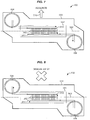
- FIG. 7 illustrates a flow of print fluid due to acceleration of carriage assembly 102 along scan direction 510 in an exemplary embodiment.
- the acceleration creates a G-force that causes the print fluid to flow in the direction indicated by the arrows. More particularly, the G-force causes the print fluid to flow from reservoir 108 to manifold 310, and from manifold 311 to reservoir 109. If jetting channels 202 in the row 302 are flow-through, then the print fluid will also flow from manifold 310 through the jetting channels 202 to manifold 311.
- FIG. 8 illustrates a flow of print fluid due to deceleration or stopping of carriage assembly 102 that was moving along scan direction 510 in an exemplary embodiment.
- carriage assembly 102 is initially moving along scan direction 510 and then decelerates or stops, this creates a G-force that causes the print fluid to flow in the direction indicated by the arrows. More particularly, the G-force causes the print fluid to flow from reservoir 109 to manifold 311, and from manifold 310 to reservoir 108. If jetting channels 202 in the row 302 are flow-through, then the print fluid will also flow from manifold 311 through the jetting channels 202 to manifold 310.
- FIG. 9 illustrates a flow of print fluid due to acceleration of carriage assembly 102 along scan direction 511 in an exemplary embodiment.
- the acceleration creates a G-force that causes the print fluid to flow in the direction indicated by the arrows. More particularly, the G-force causes the print fluid to flow from reservoir 109 to manifold 311, and from manifold 310 to reservoir 108. If jetting channels 202 in the row 302 are flow-through, then the print fluid will also flow from manifold 311 through the jetting channels 202 to manifold 310.
- FIG. 10 illustrates a flow of print fluid due to deceleration or stopping of carriage assembly 102 that was moving along scan direction 511 in an exemplary embodiment.
- carriage assembly 102 When carriage assembly 102 is initially moving along scan direction 511 and then decelerates or stops, this creates a G-force that causes the print fluid to flow in the direction indicated by the arrows. More particularly, the G-force causes the print fluid to flow from reservoir 108 to manifold 310, and from manifold 311 to reservoir 109. If jetting channels 202 in the row 302 are flow-through, then the print fluid will also flow from manifold 310 through the jetting channels 202 to manifold 311.
- FIG. 11 is another top schematic view of carriage assembly 102 in an exemplary embodiment.
- reservoirs 108-109 are mounted the same side of carriage assembly 102, and are offset from the row 302 of jetting channels 202 by different amounts.
- Reservoir 108 is offset from axis 502 by distance D1 along scan direction 510 of carriage assembly 102
- reservoir 109 is offset from axis 502 by distance D2 along scan direction 510 of carriage assembly 102.
- the distances D1 and D2 are different so that the print fluid has to travel a different distance between reservoir 108 and manifold 310 (along the scan directions 510-511) than the print fluid has to travel between reservoir 109 and manifold 311. Movement of carriage assembly 102 along the scan directions 510-511 therefore creates a differential pressure between reservoirs 108-109.
- FIG. 12 is another top schematic view of carriage assembly 102 in an exemplary embodiment.
- one reservoir 108 is offset from the row 302 of jetting channels 202, and the other reservoir 109 is mounted in-line with the row 302 of jetting channels 202.
- Reservoir 108 is offset from axis 502 by distance D1 along scan direction 510 of carriage assembly 102, and reservoir 109 is not offset but is in-line with axis 502. Again, the print fluid has to travel a different distance between reservoir 108 and manifold 310 (along the scan directions 510-511) than the print fluid has to travel between reservoir 109 and manifold 311.
- Carriage assembly 102 may be used with a flow-through printhead or a non-flow-through printhead.
- a flow-through printhead allows for ink to circulate through the jetting channels even when the jetting channels are not jetting.
- FIG. 13 illustrates a jetting channel 202 in printhead 104 in an exemplary embodiment.
- the assumption for this embodiment is that printhead 104 is a flow-through head.
- jetting channel 202 includes a restrictor 1302 that controls a flow of print fluid from a supply manifold (e.g., manifold 310) to chamber 212.
- Jetting channel 202 also includes another restrictor 1304 that controls a flow of ink from chamber 212 to a return manifold (e.g., manifold 311).
- the use of two restrictors as in FIG. 13 allows for print fluid to circulate through jetting channel 202 even when no jetting occurs.
- the flow of the print fluid is illustrated by the arrows in FIG. 13 .
- the print fluid flows from a supply manifold, through restrictor 1302, and into chamber 212.
- the print fluid then flows through restrictor 1304 (instead of exiting out of nozzle 214), and enters the return manifold.
- restrictor 1304 allows print fluid to flow out of chamber 212 instead of sitting in chamber 212 and potentially drying or settling.
Landscapes
- Ink Jet (AREA)
Abstract
Description
- The following disclosure relates to the field of printing, and in particular, to carriage assemblies for printers.
- Inkjet printing is a type of printing that propels drops of ink (also referred to as droplets) onto a medium, such as paper, a substrate for 3D printing, etc. The core of an inkjet printer includes one or more printheads (also referred to as inkjet heads) having multiple jetting channels arranged in a row to discharge drops of ink. A typical jetting channel includes a nozzle, a chamber, and a mechanism for ejecting the ink from the chamber and through the nozzle, which is typically a piezoelectric actuator connected to a diaphragm. To discharge a drop from a jetting channel, a drive circuit provides a drive waveform to the piezoelectric actuator of that jetting channel that includes a jetting pulse. In response to the jetting pulse, the piezoelectric actuator generates pressure oscillations inside of the chamber to push the drop out of the nozzle. The drive waveforms provided to individual piezoelectric actuators control how drops are ejected from each of the jetting channels.
- Shuttle-type printers are a class of printers having a movable shuttle or carriage assemble that reciprocates back and forth across a medium. A printhead is mounted on the carriage assembly, and jetting from the printhead is synchronized with movement of the carriage assembly to print desired images. Movement of the carriage assembly is also synchronized with a medium transfer mechanism that advances the medium through the printer.
- It remains an issue for manufacturers to find effective ways to supply ink or another print fluid to printheads in shuttle-type printers.
- Embodiments described herein include a carriage assembly for a printer that has one or more printheads, and independent reservoirs that supply a print fluid to the printhead. The reservoirs are mounted on the carriage assembly, and at least one of the reservoirs is offset from the printhead. When the carriage assembly accelerates and decelerates in the scan directions, force is created that causes the print fluid to flow between the reservoirs through the printhead. The motion of the carriage assembly creates a differential pressure between the reservoirs due to the way the reservoirs are mounted in an offset position, and allows ink to flow through the printhead. Thus, the printhead remains primed, and print fluid is able to be circulated through printhead without the use of a circulation pump.
- One embodiment includes an apparatus comprising a carriage assembly of a printer that reciprocates along scan directions. The carriage assembly includes at least one printhead having a row of jetting channels for ejecting a print fluid, and reservoirs mounted on the carriage assembly that each supply the print fluid to the printhead. At least one of reservoirs is mounted on the carriage assembly to be offset from the row of jetting channels.
- In another embodiment, the at least one printhead includes manifolds disposed in the printhead along the opposite sides of the row of jetting channels. A first one of the manifolds is fluidly connected to a first one of the reservoirs, and fluidly connected to each of the jetting channels. A second one of the manifolds is fluidly connected to a second one of the reservoirs, and fluidly connected to each of the jetting channels.
- In another embodiment, the first one of the manifolds is disposed in the printhead along a first side of the row of jetting channels, and parallels the row of jetting channels. The second one of the manifolds is disposed in the printhead along a second side of the row of jetting channels, and parallels the row of jetting channels.
- In another embodiment, the row of jetting channels defines an axis perpendicular to the scan directions of the carriage assembly. A first one of the reservoirs is offset from the axis by a first distance in a first scan direction, and a second one of the reservoirs is offset from the axis by a second distance in a second scan direction that is opposite the first scan direction.
- In another embodiment, the first distance and the second distance are equal.
- In another embodiment, the row of jetting channels defines an axis perpendicular to the scan directions of the carriage assembly. A first one of the reservoirs is offset from the axis by a first distance in a scan direction, a second one of the reservoirs is offset from the axis by a second distance in the scan direction, and the first distance is different than the second distance.
- In another embodiment, the at least one printhead comprises a flow-through printhead.
- Another embodiment comprises a carriage assembly of a printer that is configured to reciprocate along scan directions. The carriage assembly includes a printhead having a row of jetting channels for ejecting a print fluid, a first manifold disposed along a first side of the row of jetting channels and fluidly connected to each of the jetting channels, and a second manifold disposed along a second side of the row of jetting channels and fluidly connected to each of the jetting channels. The carriage assembly also includes a first reservoir fluidly connected to the first manifold of the printhead, and a second reservoir fluidly connected to the second manifold of the printhead. At least one of the first reservoir and the second reservoir is offset from the row of jetting channels.
- In another embodiment, the first reservoir is mounted on the carriage assembly on the first side of the row of jetting channels, and the second reservoir is mounted on the carriage assembly on the second side of the row of jetting channels.
- In another embodiment, the first reservoir and the second reservoir are mounted on the carriage assembly on the first side of the row of jetting channels.
- In another embodiment, the row of jetting channels defines an axis perpendicular to the scan directions of the carriage assembly. The first reservoir is offset from the axis by a first distance in a first scan direction, and the second reservoir is offset from the axis by a second distance in a second scan direction that is opposite the first scan direction.
- In another embodiment, the first distance and the second distance are equal.
- In another embodiment, the row of jetting channels defines an axis perpendicular to the scan directions of the carriage assembly, the first reservoir is offset from the axis by a first distance in a scan direction, the second reservoir is offset from the axis by a second distance in the scan direction, and the first distance is different than the second distance.
- In another embodiment, the printhead comprises a flow-through printhead.
- Another embodiment includes a printer comprising a carriage assembly comprising a conveyance structure that reciprocates along scan directions within the printer, and at least one printhead mounted on the conveyance structure, where the at least one printhead has a row of jetting channels for ejecting a print fluid. The carriage assembly further includes a first manifold disposed along a first side of the row of jetting channels and fluidly connected to each of the jetting channels, and a second manifold disposed along a second side of the row of jetting channels and fluidly connected to each of the jetting channels. The carriage assembly further includes a first reservoir for storing the print fluid, and a second reservoir for storing the print fluid. At least one of the first reservoir and the second reservoir is mounted on the conveyance structure offset from the row of jetting channels.
- The above summary provides a basic understanding of some aspects of the specification. This summary is not an extensive overview of the specification. It is intended to neither identify key or critical elements of the specification nor delineate any scope particular embodiments of the specification, or any scope of the claims. Its sole purpose is to present some concepts of the specification in a simplified form as a prelude to the more detailed description that is presented later.
- Some embodiments of the present disclosure are now described, by way of example only, and with reference to the accompanying drawings. The same reference number represents the same element or the same type of element on all drawings.
-
FIG. 1 is a schematic diagram of an image forming apparatus in an exemplary embodiment. -
FIG. 2 is a cross-sectional view of a set of jetting channels within a printhead. -
FIG. 3 is a schematic view of a printhead in an exemplary embodiment. -
FIG. 4 is a perspective view of a carriage assembly moving in relation to a medium in an exemplary embodiment. -
FIG. 5 is a top schematic view of a carriage assembly in an exemplary embodiment. -
FIG. 6 is another top schematic view of a carriage assembly in an exemplary embodiment. -
FIG. 7 illustrates a flow of print fluid due to acceleration of a carriage assembly along a scan direction in an exemplary embodiment. -
FIG. 8 illustrates a flow of print fluid due to deceleration or stopping of a carriage assembly that was moving along a scan direction in an exemplary embodiment. -
FIG. 9 illustrates a flow of print fluid due to acceleration of a carriage assembly along a scan direction in an exemplary embodiment. -
FIG. 10 illustrates a flow of print fluid due to deceleration or stopping of a carriage assembly that was moving along a scan direction in an exemplary embodiment. -
FIG. 11 is another top schematic view of a carriage assembly in an exemplary embodiment. -
FIG. 12 is another top schematic view of a carriage assembly in an exemplary embodiment. -
FIG. 13 illustrates a jetting channel in a printhead in an exemplary embodiment. - The figures and the following description illustrate specific exemplary embodiments. It will thus be appreciated that those skilled in the art will be able to devise various arrangements that, although not explicitly described or shown herein, embody the principles of the embodiments and are included within the scope of the embodiments. Furthermore, any examples described herein are intended to aid in understanding the principles of the embodiments, and are to be construed as being without limitation to such specifically recited examples and conditions. As a result, the inventive concept(s) is not limited to the specific embodiments or examples described below, but by the claims and their equivalents.
-
FIG. 1 is a schematic diagram of animage forming apparatus 100 in an exemplary embodiment.Image forming apparatus 100, such as a printer, is a shuttle-type apparatus that includes acarriage assembly 102.Carriage assembly 102 includes aconveyance structure 103 that reciprocates back and forth along a scan line or scan directions during operation. One or more inkjet head orprintheads 104 are mounted onconveyance structure 103.Printhead 104 is configured to ejectdrops 106 of a print fluid, such as ink (e.g., water, solvent, oil, or UV-curable), through a plurality of orifices or nozzles (not visible inFIG. 1 ). Independent reservoirs 108-109 are also mounted onconveyance structure 103. Each reservoir 108-109 is configured to store the same type of print fluid (e.g., same color of ink), and is fluidly connected toprinthead 104.Negative pressure regulators 110 may be installed between reservoirs 108-109 andprinthead 104 to regulate negative pressures of print fluid flowing from a reservoir 108-109 toprinthead 104. The height of reservoirs 108-109 may also be adjusted to create negative pressure, which may eliminate the use ofpressure regulators 110. -
Conveyance structure 103 may comprise any desired structure for mountingprinthead 104 and reservoirs 108-109. The shape ofconveyance structure 103 may vary as desired. In one embodiment,conveyance structure 103 may have the shape or profile of an inkjet cartridge or pen that are used in a printer. - The drops 106 ejected from the nozzles of
printhead 104 are directed toward a medium 112.Medium 112 comprises any type of material upon which ink or another print fluid is applied by a printhead, such as paper, card stock, transparent sheets, a substrate for 3D printing, cloth, etc. Typically, nozzles ofprinthead 104 are arranged in one or more rows so that ejection of print fluid from the nozzles causes formation of characters, symbols, images, layers of an object, etc., onmedium 112 asprinthead 104 and medium 112 are moved relative to one another.Media transport mechanism 114 moves medium 112 relative toprinthead 104. - In this embodiment,
image forming apparatus 100 is a shuttle-type apparatus, wherecarriage assembly 102 reciprocates back and forth across a surface of medium 112 (e.g., left and right inFIG. 1 ). To provide the movement ofcarriage assembly 102,image forming apparatus 100 includes acarriage movement mechanism 120 that movescarriage assembly 102 relative to medium 112 to perform print operations. For example,carriage movement mechanism 120 may include one or more elongated rods, andcarriage assembly 102 may be slidably mounted to the elongated rods to move bi-directionally over the medium 112.Carriage movement mechanism 120 may also include an actuator that slidescarriage assembly 102 along the elongated rods. -
Image forming apparatus 100 also includes aprint controller 122 that communicates withcarriage assembly 102,media transport mechanism 114, andcarriage movement mechanism 120.Print controller 122 may connect to a data source to receive printable data.Print controller 122 then controlscarriage assembly 102,media transport mechanism 114, andcarriage movement mechanism 120 to print the printable data onmedium 112 viaprinthead 104. -
FIG. 2 is a cross-sectional view of a set of jettingchannels 202 withinprinthead 104.Printhead 104 includes multiple jettingchannels 202 that are arranged in a line or row, a portion of which are illustrated inFIG. 2 . Each jettingchannel 202 includes apiezoelectric actuator 210, achamber 212, and anozzle 214.Piezoelectric actuators 210 are configured to receive drive waveforms, and to actuate or "fire" in response to a jetting pulse on the drive waveform. Firing of apiezoelectric actuator 210 in a jettingchannel 202 creates pressure waves inchamber 212 that cause jetting of droplets from itscorresponding nozzle 214. -
FIG. 3 is a schematic view ofprinthead 104 in an exemplary embodiment. InFIG. 3 , jettingchannels 202 are arranged in a straight line orrow 302 withinprinthead 104. To supply ink or another print fluid to jettingchannels 202,printhead 104 includes manifolds 310-311. A manifold comprises a groove, duct, conduit, etc., disposed substantially parallel to therow 302 of jettingchannels 202 withinprinthead 104, and fluidly connected to each jettingchannel 202 to supply ink or other print fluid. Therow 302 of jettingchannels 202 has opposing sides 330-331.Manifold 310 is disposed along oneside 330 of therow 302 of jettingchannels 202, andmanifold 311 is disposed along theopposite side 331 of therow 302 of jettingchannels 202. Manifolds 310-311 are fluidly connected to one another, such as through jettingchannels 202. For example, a print fluid may flow betweenmanifold 310 andmanifold 311 through jettingchannels 202, assuming thatprinthead 104 is a flow-through printhead. Thus, the same type of fluid (e.g., same color of ink) is supplied to both manifolds 310-311. -
Printhead 104 also includes fluid ports 320-321.Fluid port 320 provides a pathway tomanifold 310 ofprinthead 104.Fluid port 321 provides a pathway tomanifold 311 ofprinthead 104. Fluid ports 320-321 may be connected (e.g., through a supply hose) to reservoirs 108-109, respectively. - In the embodiments described herein, reservoirs 108-109 are mounted to
carriage assembly 102 along withprinthead 104, and at least one of reservoirs 108-109 are offset from therow 302 of jettingchannels 202. Thus, ascarriage assembly 102 reciprocates along the scan directions, acceleration and deceleration ofcarriage assembly 102 causes a differential pressure between reservoirs 108-109.FIG. 4 is a perspective view ofcarriage assembly 102 moving in relation to medium 112 in an exemplary embodiment.Medium 112 is fed along the paper feed direction bymedia transport mechanism 114.Carriage assembly 102 is driven to move in reciprocation along the scan directions, which are substantially perpendicular to the paper feed direction (or sub-scan direction). The drive mechanism forcarriage assembly 102 is beyond the scope of this specification, but may include a motor, a drive belt, guide rails, etc. -
FIG. 5 is a top schematic view ofcarriage assembly 102 in an exemplary embodiment.Reservoir 108 is fluidly connected tomanifold 310 ofprinthead 104 to supply a print fluid, andreservoir 109 is fluidly connected tomanifold 311 ofprinthead 104 to supply the print fluid.Manifold 310 supplies the print fluid to therow 302 of jettingchannels 202 from one side of therow 302, andmanifold 311 supplies the print fluid to therow 302 of jetting channels 202 (seeFIG. 3 ) from an opposite side of therow 302. - In this embodiment, reservoirs 108-109 are mounted an opposite sides of
carriage assembly 102, and are offset from therow 302 of jettingchannels 202. The arrangement of jettingchannels 202 defines anaxis 502 for therow 302.Axis 502 represents a line of direction or orientation of jettingchannels 202 in therow 302.Reservoir 108 is mounted onside 330 of therow 302 of jettingchannels 202, and is offset fromaxis 502 onside 330.Reservoir 109 is mounted onside 331 of therow 302 of jettingchannels 202, and is offset fromaxis 502 onside 331. To be "offset" means that a center portion of a reservoir is not inline with therow 302 of jetting channels along axis 502 (or more particularly, not in-line with its corresponding manifold, but is separated fromaxis 502 or is corresponding manifold by an amount or distance. The sides of therow 302 of jettingchannels 202/axis 502 are along the scan directions ofcarriage assembly 102. For example,reservoir 108 is offset fromaxis 502 by distance D1 along afirst scan direction 510 ofcarriage assembly 102.Reservoir 109 is offset fromaxis 502 by distance D2 along a second (opposing) scandirection 511 ofcarriage assembly 102. The distances D1 and D2 may be equal in a preferred embodiment, but may be different in other embodiments. -
FIG. 6 is another top schematic view ofcarriage assembly 102 in an exemplary embodiment. In this arrangement, reservoirs 108-109 are mounted on the same end ofcarriage assembly 102, and are offset from therow 302 of jettingchannels 202. As in the above embodiment,reservoir 108 is offset fromaxis 502 by distance D1 alongscan direction 510 ofcarriage assembly 102.Reservoir 109 is offset fromaxis 502 by distance D2 alongscan direction 511 ofcarriage assembly 102. - When reservoirs 108-109 are offset as in
FIGS. 5-6 , movement ofcarriage assembly 102 along the scan directions 510-511 creates a flow of print fluid from reservoirs 108-109 to manifolds 310-311 ofprinthead 104. This in turn provides the print fluid to therow 302 of jettingchannels 202 so that jettingchannels 202 have a supply of the print fluid for jetting.FIGS. 7-10 illustrate a flow of print fluid due to movement ofcarriage assembly 102 along the scan directions.FIG. 7 illustrates a flow of print fluid due to acceleration ofcarriage assembly 102 alongscan direction 510 in an exemplary embodiment. Whencarriage assembly 102 accelerates alongscan direction 510, the acceleration creates a G-force that causes the print fluid to flow in the direction indicated by the arrows. More particularly, the G-force causes the print fluid to flow fromreservoir 108 tomanifold 310, and frommanifold 311 toreservoir 109. If jettingchannels 202 in therow 302 are flow-through, then the print fluid will also flow frommanifold 310 through the jettingchannels 202 tomanifold 311. -
FIG. 8 illustrates a flow of print fluid due to deceleration or stopping ofcarriage assembly 102 that was moving alongscan direction 510 in an exemplary embodiment. Whencarriage assembly 102 is initially moving alongscan direction 510 and then decelerates or stops, this creates a G-force that causes the print fluid to flow in the direction indicated by the arrows. More particularly, the G-force causes the print fluid to flow fromreservoir 109 tomanifold 311, and frommanifold 310 toreservoir 108. If jettingchannels 202 in therow 302 are flow-through, then the print fluid will also flow frommanifold 311 through the jettingchannels 202 tomanifold 310. -
FIG. 9 illustrates a flow of print fluid due to acceleration ofcarriage assembly 102 alongscan direction 511 in an exemplary embodiment. Whencarriage assembly 102 accelerates alongscan direction 511, the acceleration creates a G-force that causes the print fluid to flow in the direction indicated by the arrows. More particularly, the G-force causes the print fluid to flow fromreservoir 109 tomanifold 311, and frommanifold 310 toreservoir 108. If jettingchannels 202 in therow 302 are flow-through, then the print fluid will also flow frommanifold 311 through the jettingchannels 202 tomanifold 310. -
FIG. 10 illustrates a flow of print fluid due to deceleration or stopping ofcarriage assembly 102 that was moving alongscan direction 511 in an exemplary embodiment. Whencarriage assembly 102 is initially moving alongscan direction 511 and then decelerates or stops, this creates a G-force that causes the print fluid to flow in the direction indicated by the arrows. More particularly, the G-force causes the print fluid to flow fromreservoir 108 tomanifold 310, and frommanifold 311 toreservoir 109. If jettingchannels 202 in therow 302 are flow-through, then the print fluid will also flow frommanifold 310 through the jettingchannels 202 tomanifold 311. -
FIG. 11 is another top schematic view ofcarriage assembly 102 in an exemplary embodiment. In this embodiment, reservoirs 108-109 are mounted the same side ofcarriage assembly 102, and are offset from therow 302 of jettingchannels 202 by different amounts.Reservoir 108 is offset fromaxis 502 by distance D1 alongscan direction 510 ofcarriage assembly 102, andreservoir 109 is offset fromaxis 502 by distance D2 alongscan direction 510 ofcarriage assembly 102. The distances D1 and D2 are different so that the print fluid has to travel a different distance betweenreservoir 108 and manifold 310 (along the scan directions 510-511) than the print fluid has to travel betweenreservoir 109 andmanifold 311. Movement ofcarriage assembly 102 along the scan directions 510-511 therefore creates a differential pressure between reservoirs 108-109. -
FIG. 12 is another top schematic view ofcarriage assembly 102 in an exemplary embodiment. In this embodiment, onereservoir 108 is offset from therow 302 of jettingchannels 202, and theother reservoir 109 is mounted in-line with therow 302 of jettingchannels 202.Reservoir 108 is offset fromaxis 502 by distance D1 alongscan direction 510 ofcarriage assembly 102, andreservoir 109 is not offset but is in-line withaxis 502. Again, the print fluid has to travel a different distance betweenreservoir 108 and manifold 310 (along the scan directions 510-511) than the print fluid has to travel betweenreservoir 109 andmanifold 311. Movement ofcarriage assembly 102 along the scan directions 510-511 therefore creates a differential pressure between reservoirs 108-109.Carriage assembly 102 may be used with a flow-through printhead or a non-flow-through printhead. A flow-through printhead, for example, allows for ink to circulate through the jetting channels even when the jetting channels are not jetting. -
FIG. 13 illustrates a jettingchannel 202 inprinthead 104 in an exemplary embodiment. The assumption for this embodiment is thatprinthead 104 is a flow-through head. In addition topiezoelectric actuator 210,chamber 212, andnozzle 214, jettingchannel 202 includes a restrictor 1302 that controls a flow of print fluid from a supply manifold (e.g., manifold 310) tochamber 212. Jettingchannel 202 also includes another restrictor 1304 that controls a flow of ink fromchamber 212 to a return manifold (e.g., manifold 311). The use of two restrictors as inFIG. 13 allows for print fluid to circulate through jettingchannel 202 even when no jetting occurs. The flow of the print fluid is illustrated by the arrows inFIG. 13 . During circulation, the print fluid flows from a supply manifold, throughrestrictor 1302, and intochamber 212. The print fluid then flows through restrictor 1304 (instead of exiting out of nozzle 214), and enters the return manifold. As is evident from this figure, circulation of print fluid in jettingchannel 202 is possible becauserestrictor 1304 allows print fluid to flow out ofchamber 212 instead of sitting inchamber 212 and potentially drying or settling. - Although specific embodiments were described herein, the scope of the invention is not limited to those specific embodiments. The scope of the invention is defined by the following claims and any equivalents thereof.
Claims (15)
- An apparatus comprising:a carriage assembly of a printer that reciprocates along scan directions, the carriage assembly comprising:at least one printhead having a row of jetting channels for ejecting a print fluid; andreservoirs mounted on the carriage assembly that each supply the print fluid to the printhead;wherein at least one of reservoirs is mounted on the carriage assembly to be offset from the row of jetting channels.
- The apparatus of claim 1 wherein:the at least one printhead includes manifolds disposed in the printhead along the opposite sides of the row of jetting channels;a first one of the manifolds is fluidly connected to a first one of the reservoirs, and fluidly connected to each of the jetting channels; anda second one of the manifolds is fluidly connected to a second one of the reservoirs, and fluidly connected to each of the jetting channels.
- The apparatus of claim 2 wherein:the first one of the manifolds is disposed in the printhead along a first side of the row of jetting channels, and parallels the row of jetting channels; andthe second one of the manifolds is disposed in the printhead along a second side of the row of jetting channels, and parallels the row of jetting channels.
- The apparatus of claim 1 wherein:the row of jetting channels defines an axis perpendicular to the scan directions of the carriage assembly;a first one of the reservoirs is offset from the axis by a first distance in a first scan direction; anda second one of the reservoirs is offset from the axis by a second distance in a second scan direction that is opposite the first scan direction.
- The apparatus of claim 4 wherein:the first distance and the second distance are equal.
- The apparatus of claim 1 wherein:the row of jetting channels defines an axis perpendicular to the scan directions of the carriage assembly;a first one of the reservoirs is offset from the axis by a first distance in a scan direction;a second one of the reservoirs is offset from the axis by a second distance in the scan direction; andthe first distance is different than the second distance.
- The apparatus of claim 1 wherein:the at least one printhead comprises a flow-through printhead.
- An apparatus comprising:a carriage assembly of a printer that is configured to reciprocate along scan directions, the carriage assembly comprising:a printhead having a row of jetting channels for ejecting a print fluid, a first manifold disposed along a first side of the row of jetting channels and fluidly connected to each of the jetting channels, and a second manifold disposed along a second side of the row of jetting channels and fluidly connected to each of the jetting channels;a first reservoir fluidly connected to the first manifold of the printhead; anda second reservoir fluidly connected to the second manifold of the printhead;wherein at least one of the first reservoir and the second reservoir is offset from the row of jetting channels.
- The apparatus of claim 8 wherein:the first reservoir is mounted on the carriage assembly on the first side of the row of jetting channels; andthe second reservoir is mounted on the carriage assembly on the second side of the row of jetting channels.
- The apparatus of claim 8 wherein:the first reservoir and the second reservoir are mounted on the carriage assembly on the first side of the row of jetting channels.
- The apparatus of claim 8 wherein:the row of jetting channels defines an axis perpendicular to the scan directions of the carriage assembly;the first reservoir is offset from the axis by a first distance in a first scan direction; andthe second reservoir is offset from the axis by a second distance in a second scan direction that is opposite the first scan direction.
- The apparatus of claim 11 wherein:the first distance and the second distance are equal.
- The apparatus of claim 8 wherein:the row of jetting channels defines an axis perpendicular to the scan directions of the carriage assembly;the first reservoir is offset from the axis by a first distance in a scan direction;the second reservoir is offset from the axis by a second distance in the scan direction; andthe first distance is different than the second distance.
- The apparatus of claim 8 wherein:the printhead comprises a flow-through printhead.
- A printer comprising:a carriage assembly comprising:a conveyance structure that reciprocates along scan directions within the printer;at least one printhead mounted on the conveyance structure, wherein the at least one printhead has a row of jetting channels for ejecting a print fluid, a first manifold disposed along a first side of the row of jetting channels and fluidly connected to each of the jetting channels, and a second manifold disposed along a second side of the row of jetting channels and fluidly connected to each of the jetting channels;a first reservoir for storing the print fluid; anda second reservoir for storing the print fluid;wherein at least one of the first reservoir and the second reservoir is mounted on the conveyance structure offset from the row of jetting channels.
Applications Claiming Priority (1)
| Application Number | Priority Date | Filing Date | Title |
|---|---|---|---|
| US15/443,520 US10016991B1 (en) | 2017-02-27 | 2017-02-27 | Carriage assembly for a printer having independent reservoirs |
Publications (2)
| Publication Number | Publication Date |
|---|---|
| EP3369574A1 true EP3369574A1 (en) | 2018-09-05 |
| EP3369574B1 EP3369574B1 (en) | 2022-03-02 |
Family
ID=61024689
Family Applications (1)
| Application Number | Title | Priority Date | Filing Date |
|---|---|---|---|
| EP18153277.1A Active EP3369574B1 (en) | 2017-02-27 | 2018-01-24 | Carriage assembly for a printer having independent reservoirs |
Country Status (3)
| Country | Link |
|---|---|
| US (2) | US10016991B1 (en) |
| EP (1) | EP3369574B1 (en) |
| CN (1) | CN108501531B (en) |
Families Citing this family (5)
| Publication number | Priority date | Publication date | Assignee | Title |
|---|---|---|---|---|
| JP2020124817A (en) * | 2019-02-01 | 2020-08-20 | 東芝テック株式会社 | Inkjet recording device |
| JP7404638B2 (en) | 2019-04-01 | 2023-12-26 | ブラザー工業株式会社 | liquid discharge head |
| JP7310320B2 (en) * | 2019-06-03 | 2023-07-19 | ブラザー工業株式会社 | LIQUID EJECTION HEAD AND LIQUID EJECTION APPARATUS INCLUDING THE SAME |
| JP7326900B2 (en) * | 2019-06-12 | 2023-08-16 | ブラザー工業株式会社 | liquid ejection head |
| JP7552266B2 (en) * | 2020-11-09 | 2024-09-18 | 株式会社リコー | Liquid ejection head, ejection unit, and liquid ejection device |
Citations (7)
| Publication number | Priority date | Publication date | Assignee | Title |
|---|---|---|---|---|
| WO2006060622A2 (en) * | 2004-12-03 | 2006-06-08 | Fujifilm Dimatix, Inc. | Printheads and systems using printheads |
| US20070176985A1 (en) * | 2006-02-02 | 2007-08-02 | Yoshio Takeuchi | Liquid jetting head and liquid jetting apparatus |
| JP2008149594A (en) * | 2006-12-19 | 2008-07-03 | Toshiba Tec Corp | Inkjet recording device |
| US20080266365A1 (en) * | 2007-04-27 | 2008-10-30 | Samsung Electro-Mechanics Co., Ltd. | Ink-jet head |
| US20090009565A1 (en) * | 2007-07-03 | 2009-01-08 | Samsung Electronics Co., Ltd. | Piezoelectric inkjet head |
| US20100327025A1 (en) * | 2009-06-30 | 2010-12-30 | Canon Kabushiki Kaisha | Liquid discharging apparatus |
| US20150183227A1 (en) * | 2013-12-27 | 2015-07-02 | Toshiba Tec Kabushiki Kaisha | Liquid circulation device and liquid discharging apparatus |
Family Cites Families (4)
| Publication number | Priority date | Publication date | Assignee | Title |
|---|---|---|---|---|
| JP5209431B2 (en) * | 2008-09-30 | 2013-06-12 | 富士フイルム株式会社 | Inkjet recording device |
| US8235494B2 (en) * | 2010-02-18 | 2012-08-07 | Kabushiki Kaisha Toshiba | Image forming apparatus and ejection liquid circulating method |
| US8517522B2 (en) * | 2011-02-07 | 2013-08-27 | Fujifilm Dimatix, Inc. | Fluid circulation |
| US8454145B1 (en) * | 2011-11-29 | 2013-06-04 | Eastman Kodak Company | Air extraction momentum pump for inkjet printhead |
-
2017
- 2017-02-27 US US15/443,520 patent/US10016991B1/en active Active
-
2018
- 2018-01-24 EP EP18153277.1A patent/EP3369574B1/en active Active
- 2018-02-12 CN CN201810145100.1A patent/CN108501531B/en active Active
- 2018-06-18 US US16/011,589 patent/US10350921B2/en not_active Expired - Fee Related
Patent Citations (7)
| Publication number | Priority date | Publication date | Assignee | Title |
|---|---|---|---|---|
| WO2006060622A2 (en) * | 2004-12-03 | 2006-06-08 | Fujifilm Dimatix, Inc. | Printheads and systems using printheads |
| US20070176985A1 (en) * | 2006-02-02 | 2007-08-02 | Yoshio Takeuchi | Liquid jetting head and liquid jetting apparatus |
| JP2008149594A (en) * | 2006-12-19 | 2008-07-03 | Toshiba Tec Corp | Inkjet recording device |
| US20080266365A1 (en) * | 2007-04-27 | 2008-10-30 | Samsung Electro-Mechanics Co., Ltd. | Ink-jet head |
| US20090009565A1 (en) * | 2007-07-03 | 2009-01-08 | Samsung Electronics Co., Ltd. | Piezoelectric inkjet head |
| US20100327025A1 (en) * | 2009-06-30 | 2010-12-30 | Canon Kabushiki Kaisha | Liquid discharging apparatus |
| US20150183227A1 (en) * | 2013-12-27 | 2015-07-02 | Toshiba Tec Kabushiki Kaisha | Liquid circulation device and liquid discharging apparatus |
Also Published As
| Publication number | Publication date |
|---|---|
| US20180297381A1 (en) | 2018-10-18 |
| US10350921B2 (en) | 2019-07-16 |
| EP3369574B1 (en) | 2022-03-02 |
| US10016991B1 (en) | 2018-07-10 |
| CN108501531B (en) | 2021-08-31 |
| CN108501531A (en) | 2018-09-07 |
Similar Documents
| Publication | Publication Date | Title |
|---|---|---|
| US10350921B2 (en) | Carriage assembly for a printer having independent reservoirs | |
| EP3708371B1 (en) | Flow-through printhead with bypass manifold | |
| US11230097B2 (en) | Fluid ejection device | |
| US10717274B2 (en) | Fluid ejection device | |
| US10766272B2 (en) | Fluid ejection device | |
| US10632749B2 (en) | Fluid ejection device | |
| US10207516B2 (en) | Fluid ejection device | |
| US10850511B2 (en) | Fluid ejection device | |
| EP3536507B1 (en) | Independent reservoirs and method for supplying a print fluid to a flow-through printhead | |
| US11059290B2 (en) | Fluid ejection device | |
| US10780705B2 (en) | Fluid ejection device | |
| US20200031135A1 (en) | Fluid ejection device |
Legal Events
| Date | Code | Title | Description |
|---|---|---|---|
| PUAI | Public reference made under article 153(3) epc to a published international application that has entered the european phase |
Free format text: ORIGINAL CODE: 0009012 |
|
| STAA | Information on the status of an ep patent application or granted ep patent |
Free format text: STATUS: REQUEST FOR EXAMINATION WAS MADE |
|
| 17P | Request for examination filed |
Effective date: 20180124 |
|
| AK | Designated contracting states |
Kind code of ref document: A1 Designated state(s): AL AT BE BG CH CY CZ DE DK EE ES FI FR GB GR HR HU IE IS IT LI LT LU LV MC MK MT NL NO PL PT RO RS SE SI SK SM TR |
|
| AX | Request for extension of the european patent |
Extension state: BA ME |
|
| RAP1 | Party data changed (applicant data changed or rights of an application transferred) |
Owner name: RICOH COMPANY, LTD. |
|
| STAA | Information on the status of an ep patent application or granted ep patent |
Free format text: STATUS: EXAMINATION IS IN PROGRESS |
|
| 17Q | First examination report despatched |
Effective date: 20201130 |
|
| GRAP | Despatch of communication of intention to grant a patent |
Free format text: ORIGINAL CODE: EPIDOSNIGR1 |
|
| STAA | Information on the status of an ep patent application or granted ep patent |
Free format text: STATUS: GRANT OF PATENT IS INTENDED |
|
| INTG | Intention to grant announced |
Effective date: 20211108 |
|
| GRAS | Grant fee paid |
Free format text: ORIGINAL CODE: EPIDOSNIGR3 |
|
| GRAA | (expected) grant |
Free format text: ORIGINAL CODE: 0009210 |
|
| STAA | Information on the status of an ep patent application or granted ep patent |
Free format text: STATUS: THE PATENT HAS BEEN GRANTED |
|
| AK | Designated contracting states |
Kind code of ref document: B1 Designated state(s): AL AT BE BG CH CY CZ DE DK EE ES FI FR GB GR HR HU IE IS IT LI LT LU LV MC MK MT NL NO PL PT RO RS SE SI SK SM TR |
|
| REG | Reference to a national code |
Ref country code: GB Ref legal event code: FG4D |
|
| REG | Reference to a national code |
Ref country code: CH Ref legal event code: EP Ref country code: AT Ref legal event code: REF Ref document number: 1471927 Country of ref document: AT Kind code of ref document: T Effective date: 20220315 |
|
| REG | Reference to a national code |
Ref country code: DE Ref legal event code: R096 Ref document number: 602018031463 Country of ref document: DE |
|
| REG | Reference to a national code |
Ref country code: IE Ref legal event code: FG4D |
|
| REG | Reference to a national code |
Ref country code: NL Ref legal event code: FP |
|
| REG | Reference to a national code |
Ref country code: LT Ref legal event code: MG9D |
|
| PG25 | Lapsed in a contracting state [announced via postgrant information from national office to epo] |
Ref country code: SE Free format text: LAPSE BECAUSE OF FAILURE TO SUBMIT A TRANSLATION OF THE DESCRIPTION OR TO PAY THE FEE WITHIN THE PRESCRIBED TIME-LIMIT Effective date: 20220302 Ref country code: RS Free format text: LAPSE BECAUSE OF FAILURE TO SUBMIT A TRANSLATION OF THE DESCRIPTION OR TO PAY THE FEE WITHIN THE PRESCRIBED TIME-LIMIT Effective date: 20220302 Ref country code: NO Free format text: LAPSE BECAUSE OF FAILURE TO SUBMIT A TRANSLATION OF THE DESCRIPTION OR TO PAY THE FEE WITHIN THE PRESCRIBED TIME-LIMIT Effective date: 20220602 Ref country code: LT Free format text: LAPSE BECAUSE OF FAILURE TO SUBMIT A TRANSLATION OF THE DESCRIPTION OR TO PAY THE FEE WITHIN THE PRESCRIBED TIME-LIMIT Effective date: 20220302 Ref country code: HR Free format text: LAPSE BECAUSE OF FAILURE TO SUBMIT A TRANSLATION OF THE DESCRIPTION OR TO PAY THE FEE WITHIN THE PRESCRIBED TIME-LIMIT Effective date: 20220302 Ref country code: ES Free format text: LAPSE BECAUSE OF FAILURE TO SUBMIT A TRANSLATION OF THE DESCRIPTION OR TO PAY THE FEE WITHIN THE PRESCRIBED TIME-LIMIT Effective date: 20220302 Ref country code: BG Free format text: LAPSE BECAUSE OF FAILURE TO SUBMIT A TRANSLATION OF THE DESCRIPTION OR TO PAY THE FEE WITHIN THE PRESCRIBED TIME-LIMIT Effective date: 20220602 |
|
| REG | Reference to a national code |
Ref country code: AT Ref legal event code: MK05 Ref document number: 1471927 Country of ref document: AT Kind code of ref document: T Effective date: 20220302 |
|
| PG25 | Lapsed in a contracting state [announced via postgrant information from national office to epo] |
Ref country code: PL Free format text: LAPSE BECAUSE OF FAILURE TO SUBMIT A TRANSLATION OF THE DESCRIPTION OR TO PAY THE FEE WITHIN THE PRESCRIBED TIME-LIMIT Effective date: 20220302 Ref country code: LV Free format text: LAPSE BECAUSE OF FAILURE TO SUBMIT A TRANSLATION OF THE DESCRIPTION OR TO PAY THE FEE WITHIN THE PRESCRIBED TIME-LIMIT Effective date: 20220302 Ref country code: GR Free format text: LAPSE BECAUSE OF FAILURE TO SUBMIT A TRANSLATION OF THE DESCRIPTION OR TO PAY THE FEE WITHIN THE PRESCRIBED TIME-LIMIT Effective date: 20220603 Ref country code: FI Free format text: LAPSE BECAUSE OF FAILURE TO SUBMIT A TRANSLATION OF THE DESCRIPTION OR TO PAY THE FEE WITHIN THE PRESCRIBED TIME-LIMIT Effective date: 20220302 |
|
| PG25 | Lapsed in a contracting state [announced via postgrant information from national office to epo] |
Ref country code: SM Free format text: LAPSE BECAUSE OF FAILURE TO SUBMIT A TRANSLATION OF THE DESCRIPTION OR TO PAY THE FEE WITHIN THE PRESCRIBED TIME-LIMIT Effective date: 20220302 Ref country code: SK Free format text: LAPSE BECAUSE OF FAILURE TO SUBMIT A TRANSLATION OF THE DESCRIPTION OR TO PAY THE FEE WITHIN THE PRESCRIBED TIME-LIMIT Effective date: 20220302 Ref country code: RO Free format text: LAPSE BECAUSE OF FAILURE TO SUBMIT A TRANSLATION OF THE DESCRIPTION OR TO PAY THE FEE WITHIN THE PRESCRIBED TIME-LIMIT Effective date: 20220302 Ref country code: PT Free format text: LAPSE BECAUSE OF FAILURE TO SUBMIT A TRANSLATION OF THE DESCRIPTION OR TO PAY THE FEE WITHIN THE PRESCRIBED TIME-LIMIT Effective date: 20220704 Ref country code: EE Free format text: LAPSE BECAUSE OF FAILURE TO SUBMIT A TRANSLATION OF THE DESCRIPTION OR TO PAY THE FEE WITHIN THE PRESCRIBED TIME-LIMIT Effective date: 20220302 Ref country code: CZ Free format text: LAPSE BECAUSE OF FAILURE TO SUBMIT A TRANSLATION OF THE DESCRIPTION OR TO PAY THE FEE WITHIN THE PRESCRIBED TIME-LIMIT Effective date: 20220302 Ref country code: AT Free format text: LAPSE BECAUSE OF FAILURE TO SUBMIT A TRANSLATION OF THE DESCRIPTION OR TO PAY THE FEE WITHIN THE PRESCRIBED TIME-LIMIT Effective date: 20220302 |
|
| PG25 | Lapsed in a contracting state [announced via postgrant information from national office to epo] |
Ref country code: IS Free format text: LAPSE BECAUSE OF FAILURE TO SUBMIT A TRANSLATION OF THE DESCRIPTION OR TO PAY THE FEE WITHIN THE PRESCRIBED TIME-LIMIT Effective date: 20220702 Ref country code: AL Free format text: LAPSE BECAUSE OF FAILURE TO SUBMIT A TRANSLATION OF THE DESCRIPTION OR TO PAY THE FEE WITHIN THE PRESCRIBED TIME-LIMIT Effective date: 20220302 |
|
| REG | Reference to a national code |
Ref country code: DE Ref legal event code: R097 Ref document number: 602018031463 Country of ref document: DE |
|
| PLBE | No opposition filed within time limit |
Free format text: ORIGINAL CODE: 0009261 |
|
| STAA | Information on the status of an ep patent application or granted ep patent |
Free format text: STATUS: NO OPPOSITION FILED WITHIN TIME LIMIT |
|
| PG25 | Lapsed in a contracting state [announced via postgrant information from national office to epo] |
Ref country code: DK Free format text: LAPSE BECAUSE OF FAILURE TO SUBMIT A TRANSLATION OF THE DESCRIPTION OR TO PAY THE FEE WITHIN THE PRESCRIBED TIME-LIMIT Effective date: 20220302 |
|
| 26N | No opposition filed |
Effective date: 20221205 |
|
| PG25 | Lapsed in a contracting state [announced via postgrant information from national office to epo] |
Ref country code: SI Free format text: LAPSE BECAUSE OF FAILURE TO SUBMIT A TRANSLATION OF THE DESCRIPTION OR TO PAY THE FEE WITHIN THE PRESCRIBED TIME-LIMIT Effective date: 20220302 |
|
| P01 | Opt-out of the competence of the unified patent court (upc) registered |
Effective date: 20230522 |
|
| PG25 | Lapsed in a contracting state [announced via postgrant information from national office to epo] |
Ref country code: IT Free format text: LAPSE BECAUSE OF FAILURE TO SUBMIT A TRANSLATION OF THE DESCRIPTION OR TO PAY THE FEE WITHIN THE PRESCRIBED TIME-LIMIT Effective date: 20220302 |
|
| REG | Reference to a national code |
Ref country code: CH Ref legal event code: PL |
|
| PG25 | Lapsed in a contracting state [announced via postgrant information from national office to epo] |
Ref country code: LU Free format text: LAPSE BECAUSE OF NON-PAYMENT OF DUE FEES Effective date: 20230124 |
|
| REG | Reference to a national code |
Ref country code: BE Ref legal event code: MM Effective date: 20230131 |
|
| PG25 | Lapsed in a contracting state [announced via postgrant information from national office to epo] |
Ref country code: LI Free format text: LAPSE BECAUSE OF NON-PAYMENT OF DUE FEES Effective date: 20230131 Ref country code: CH Free format text: LAPSE BECAUSE OF NON-PAYMENT OF DUE FEES Effective date: 20230131 |
|
| PG25 | Lapsed in a contracting state [announced via postgrant information from national office to epo] |
Ref country code: BE Free format text: LAPSE BECAUSE OF NON-PAYMENT OF DUE FEES Effective date: 20230131 |
|
| PG25 | Lapsed in a contracting state [announced via postgrant information from national office to epo] |
Ref country code: IE Free format text: LAPSE BECAUSE OF NON-PAYMENT OF DUE FEES Effective date: 20230124 |
|
| PG25 | Lapsed in a contracting state [announced via postgrant information from national office to epo] |
Ref country code: MC Free format text: LAPSE BECAUSE OF FAILURE TO SUBMIT A TRANSLATION OF THE DESCRIPTION OR TO PAY THE FEE WITHIN THE PRESCRIBED TIME-LIMIT Effective date: 20220302 |
|
| PG25 | Lapsed in a contracting state [announced via postgrant information from national office to epo] |
Ref country code: MC Free format text: LAPSE BECAUSE OF FAILURE TO SUBMIT A TRANSLATION OF THE DESCRIPTION OR TO PAY THE FEE WITHIN THE PRESCRIBED TIME-LIMIT Effective date: 20220302 |
|
| PG25 | Lapsed in a contracting state [announced via postgrant information from national office to epo] |
Ref country code: CY Free format text: LAPSE BECAUSE OF FAILURE TO SUBMIT A TRANSLATION OF THE DESCRIPTION OR TO PAY THE FEE WITHIN THE PRESCRIBED TIME-LIMIT; INVALID AB INITIO Effective date: 20180124 |
|
| PG25 | Lapsed in a contracting state [announced via postgrant information from national office to epo] |
Ref country code: HU Free format text: LAPSE BECAUSE OF FAILURE TO SUBMIT A TRANSLATION OF THE DESCRIPTION OR TO PAY THE FEE WITHIN THE PRESCRIBED TIME-LIMIT; INVALID AB INITIO Effective date: 20180124 |
|
| PG25 | Lapsed in a contracting state [announced via postgrant information from national office to epo] |
Ref country code: TR Free format text: LAPSE BECAUSE OF FAILURE TO SUBMIT A TRANSLATION OF THE DESCRIPTION OR TO PAY THE FEE WITHIN THE PRESCRIBED TIME-LIMIT Effective date: 20220302 |
|
| PGFP | Annual fee paid to national office [announced via postgrant information from national office to epo] |
Ref country code: NL Payment date: 20260121 Year of fee payment: 9 |
|
| PGFP | Annual fee paid to national office [announced via postgrant information from national office to epo] |
Ref country code: GB Payment date: 20260123 Year of fee payment: 9 |
|
| PGFP | Annual fee paid to national office [announced via postgrant information from national office to epo] |
Ref country code: DE Payment date: 20260121 Year of fee payment: 9 |
|
| PGFP | Annual fee paid to national office [announced via postgrant information from national office to epo] |
Ref country code: FR Payment date: 20260123 Year of fee payment: 9 |