EP3369372A1 - Soft gripper and blood pressure measuring cuff comprising same - Google Patents
Soft gripper and blood pressure measuring cuff comprising same Download PDFInfo
- Publication number
- EP3369372A1 EP3369372A1 EP16870217.3A EP16870217A EP3369372A1 EP 3369372 A1 EP3369372 A1 EP 3369372A1 EP 16870217 A EP16870217 A EP 16870217A EP 3369372 A1 EP3369372 A1 EP 3369372A1
- Authority
- EP
- European Patent Office
- Prior art keywords
- fluid
- actuators
- actuator
- soft gripper
- leading end
- Prior art date
- Legal status (The legal status is an assumption and is not a legal conclusion. Google has not performed a legal analysis and makes no representation as to the accuracy of the status listed.)
- Granted
Links
Images












Classifications
-
- A—HUMAN NECESSITIES
- A61—MEDICAL OR VETERINARY SCIENCE; HYGIENE
- A61B—DIAGNOSIS; SURGERY; IDENTIFICATION
- A61B5/00—Measuring for diagnostic purposes; Identification of persons
- A61B5/02—Detecting, measuring or recording for evaluating the cardiovascular system, e.g. pulse, heart rate, blood pressure or blood flow
- A61B5/021—Measuring pressure in heart or blood vessels
- A61B5/022—Measuring pressure in heart or blood vessels by applying pressure to close blood vessels, e.g. against the skin; Ophthalmodynamometers
- A61B5/02233—Occluders specially adapted therefor
-
- A—HUMAN NECESSITIES
- A61—MEDICAL OR VETERINARY SCIENCE; HYGIENE
- A61B—DIAGNOSIS; SURGERY; IDENTIFICATION
- A61B5/00—Measuring for diagnostic purposes; Identification of persons
- A61B5/02—Detecting, measuring or recording for evaluating the cardiovascular system, e.g. pulse, heart rate, blood pressure or blood flow
- A61B5/021—Measuring pressure in heart or blood vessels
- A61B5/02141—Details of apparatus construction, e.g. pump units or housings therefor, cuff pressurising systems, arrangements of fluid conduits or circuits
-
- A—HUMAN NECESSITIES
- A61—MEDICAL OR VETERINARY SCIENCE; HYGIENE
- A61B—DIAGNOSIS; SURGERY; IDENTIFICATION
- A61B5/00—Measuring for diagnostic purposes; Identification of persons
- A61B5/02—Detecting, measuring or recording for evaluating the cardiovascular system, e.g. pulse, heart rate, blood pressure or blood flow
- A61B5/021—Measuring pressure in heart or blood vessels
- A61B5/02108—Measuring pressure in heart or blood vessels from analysis of pulse wave characteristics
- A61B5/02116—Measuring pressure in heart or blood vessels from analysis of pulse wave characteristics of pulse wave amplitude
-
- A—HUMAN NECESSITIES
- A61—MEDICAL OR VETERINARY SCIENCE; HYGIENE
- A61B—DIAGNOSIS; SURGERY; IDENTIFICATION
- A61B5/00—Measuring for diagnostic purposes; Identification of persons
- A61B5/02—Detecting, measuring or recording for evaluating the cardiovascular system, e.g. pulse, heart rate, blood pressure or blood flow
- A61B5/021—Measuring pressure in heart or blood vessels
- A61B5/022—Measuring pressure in heart or blood vessels by applying pressure to close blood vessels, e.g. against the skin; Ophthalmodynamometers
-
- B—PERFORMING OPERATIONS; TRANSPORTING
- B25—HAND TOOLS; PORTABLE POWER-DRIVEN TOOLS; MANIPULATORS
- B25J—MANIPULATORS; CHAMBERS PROVIDED WITH MANIPULATION DEVICES
- B25J9/00—Program-controlled manipulators
- B25J9/10—Program-controlled manipulators characterised by positioning means for manipulator elements
- B25J9/14—Program-controlled manipulators characterised by positioning means for manipulator elements fluid
- B25J9/142—Program-controlled manipulators characterised by positioning means for manipulator elements fluid comprising inflatable bodies
Definitions
- the present invention relates to a soft gripper, more particularly to a soft gripper that automatically surrounds and grips an object using air pressure.
- the present invention also relates to a blood pressure measuring cuff provided with the soft gripper.
- Patent Literature 1 JP 2013-220321 A discloses that a subject wears a blood pressure measuring cuff while wrapping the blood pressure measuring cuff around an upper arm during measurement.
- Patent Literature 1 JP 2013-220321 A
- An object of the present invention is to provide a soft gripper that can automatically surround and grip the object while adapting to the thickness of the object (including a region to be measured such as the arm).
- Another object of the present invention is to provide a blood pressure measuring cuff, which includes the soft gripper and can be mounted by automatically surrounding the region to be measured.
- the soft gripper for fixing a human body of the present invention comprises:
- the “base” means an end on the side of a connection portion where the first actuator and the second actuator are connected to each other.
- the “leading end” means an end on the opposite side to the "base”.
- each of the first and second actuators when receiving the supply of the fluid, sequentially surrounds the object from the base or a specific point between the base and the leading end toward the side of the leading end.
- the soft gripper of this embodiment it becomes possible to automatically surround and grip the object using the first and second actuators.
- the fluid is exhausted from the first and second actuators to which the fluid was supplied. Consequently, the bending states of the first and second actuators, which are bent to surround the object, are eliminated, and the first and second actuators are detached from the object.
- bending rigidity on a side of the base is smaller than bending rigidity on the side of the leading end.
- the soft gripper of the present invention when the same pressure is applied to the first and second actuators, the first and second actuators are bent from the side of the base toward the side of the leading end to surround the object. In such a case, pressurization control is easily performed when the first and second actuators are bent. If the bending rigidity of each of the first and second actuators were uniform in the longitudinal direction, the pressurization would be performed at a plurality of levels in the longitudinal direction of the first and second actuators, making the pressurization control complicated and troublesome.
- each of the first and second actuators includes a flexible plate and a fluid bag stuck to the flexible plate, each of the fluid bags includes a plurality of expandable pleats that are formed while divided in a length direction, each of the fluid bags includes first and second air supply ports that supply the fluid, and each of the fluid bags is separately pressurized by receiving the supply of the fluid from an outside through the first or second air supply port.
- the "outside” means an outside of the soft gripper.
- the timing at which the leading end of the first actuator is bent along the outer peripheral surface of the object and the timing at which the leading end of the second actuator is bent along the outer peripheral surface of the object can separately be controlled.
- the first actuator is sequentially bent from the side of the base toward the side of the leading end
- the second actuator is sequentially bent from the side of the base toward the side of the leading end.
- each of the first and second actuators includes a fluid bag
- each of the fluid bags includes a plurality of expandable pleats that are formed while divided in a length direction, and a first throttle that is provided at one or a plurality of points so as to be sequentially bent from the base or the specific point toward the side of the leading end in the length direction
- each of the fluid bags includes first and second air supply ports that receive the supply of the fluid at the base, and each of the fluid bags is pressurized by receiving the supply of the fluid from an outside through the first or second air supply port.
- each of the fluid bags receives the supply of the fluid from the outside through the first or second air supply port.
- the fluid is supplied from the side of the base toward the side of the leading end through the first throttles provided at one or a plurality of points in the length direction. Consequently, each of the fluid bags is sequentially bent from the base or the specific point toward the side of the leading end in the length direction.
- the fluid bags are separately pressurized. Consequently, it is possible to control timing at which the leading end of the first actuator is bent along an outer peripheral surface of the object, and timing at which the leading end of the second actuator is bent along an outer peripheral surface of the object. For example, the first actuator is sequentially bent from the side of the base toward the side of the leading end, and then the second actuator is sequentially bent from the side of the base toward the side of the leading end.
- each of the fluid bags includes along the length direction, a first portion of large-swelling and a second portion of swelling smaller than that of the first portion.
- the bending force is large in the large-swelling portion and the bending force is small in the small-swelling portion.
- the large-swelling portion having the large bending force moves similarly to a joint of a human finger
- the small-swelling portion having the small bending force moves similarly to the finger other than the joint.
- the soft gripper of this embodiment when the object is surrounded by the first and second actuators, the first fixing element and the second fixing element are fixed to each other while overlapping each other.
- the object can firmly be fixed with the soft gripper by receiving the supply of the fluid from the outside.
- a detaching fluid bag that receives the supply of the fluid from the outside to detach the first and second fixing elements from each other is disposed at positions corresponding to the first and second fixing elements.
- the fixing between the first fixing element and the second fixing element is automatically released when the detaching fluid bag receives the supply of the fluid.
- the fixing between the first and second actuators can automatically be released.
- a stretching fluid bag is provided along each surface side of the first and second actuators which comes into contact with the object, so as to eliminate the bending of the first and second actuators and stretch the first and second actuators when the stretching fluid bag receives the supply of the fluid from the outside.
- the speed at which the first and second actuators are stretched can be enhanced when the stretching fluid bag receives the supply of the fluid from the outside.
- opening times of the first and second actuators can be shortened.
- one of the sides of the leading ends of the first and second actuators is divided into two portions, and the other side of the leading end of the first and second actuators is disposed between the two divided portions.
- the soft gripper of this embodiment with respect to the width direction perpendicular to the longitudinal direction in which the first and second actuators extend, one of the sides of the leading ends of the first and second actuators is divided in two portions, and the other side of the leading end of the first and second actuators is disposed between the two divided portions.
- the soft gripper can wind around the object without a gap when surrounding the object.
- one of the sides of the leading ends of the first and second actuators is divided into a plurality of portions, and the other side of the leading end of the first and second actuators is disposed between the plurality of divided portions.
- the soft gripper of this embodiment with respect to the width direction perpendicular to the longitudinal direction in which the first and second actuators extend, one of the sides of the leading ends of the first and second actuators is divided in two portions, and the other side of the leading end of the first and second actuators is disposed between the two divided portions.
- the soft gripper can wind around the object without a gap when surrounding the object.
- the object has an elongated shape in one direction
- the soft gripper further comprising: a pressurization unit that sequentially pressurizes the first and second actuators from one side to the other side in an elongated direction of the object.
- the object having an elongated shape can sequentially be wound around from one side to the other side in the elongated direction of the object.
- the pressurization unit includes one flow path that receives the supply of the fluid from the outside to its one end, and a second throttle interposed between a portion connected to the first actuator in the flow path and a portion connected to the second actuator in the flow path.
- the timing of supplying the fluid from the hydraulic pump to each fluid bag can be changed by the simple configuration in which the throttle (second throttle) is interposed in one flow path, such as the tube, which passes the fluid.
- the timings at which the plurality of portions of the divided leading ends of the first and second actuators are bent along the outer peripheral surface of the object can be controlled.
- the first or second actuator in a natural state, has a shape bent or folded on an opposite side to a direction in which the object is surrounded.
- the apparent dimension in the longitudinal direction of the soft gripper can be shortened. Since the size of the soft gripper can be further miniaturized, thus a volume for storage can further be reduced. Therefore, the storage is facilitated.
- the first or second actuator sequentially surrounds the object while releasing the bending or the folding.
- the soft gripper of this embodiment sequentially surrounds the object while releasing the bending or the folding. With this configuration, the object can be surrounded even for the narrow space around the soft gripper.
- a blood pressure measuring cuff of the present invention comprises the above described soft gripper.
- the soft gripper provided in the blood pressure measuring cuff surrounds the object in a manner that each of the first and second actuators sequentially surrounds it from the base or the specific point between the base and the leading end toward the side of the leading end.
- the object in the soft gripper and the blood pressure measuring cuff of the present invention, the object can automatically be surrounded and gripped.
- Fig. 1 is a top view illustrating an appearance of a blood pressure measuring cuff according to a first embodiment of the present invention
- Fig. 2 is an exploded perspective view illustrating a structure of the blood pressure measuring cuff in Fig. 1
- the blood pressure measuring cuff in Fig. 1 includes a measurement air bag 11 used to measure a blood pressure and a soft gripper 1.
- the soft gripper 1 includes an elongated first actuator 2 deformed by receiving supply of fluid, an elongated second actuator 3 deformed by receiving supply of fluid, a base plastic film 12 welding the first actuator 2 and the second actuator 3, and a Hook-and-Loop fastener 4 that detachably attaches the measurement air bag 11.
- the first actuator 2 includes a first bending type actuator unit 2a and a second bending type actuator unit 2b, in each of which the fluid can be stored.
- the second actuator 3 includes a first bending type actuator unit 3a and a second bending type actuator unit 3b, in each of which the fluid can be stored.
- the first actuator 2 and the second actuator 3 extend from bases n toward opposite sides to each other.
- each of the first and second actuators 2, 3 sequentially surrounds an object from the base n toward a side of leading end s of the each of the first and second actuators 2, 3.
- the soft gripper 1 is detached from the object, the fluid is exhausted from the first and second actuators 2, 3 to which the fluid was supplied. Consequently, bending states of the first and second actuators 2, 3 surrounding the object in a curved manner are eliminated, and the first and second actuators 2, 3 are detached from the object.
- the soft gripper can wind around the object without a gap when surrounding the object.
- the measurement air bag 11 Since the measurement air bag 11 needs to be changed according to a human arm diameter after being wound around an upper arm 90, the measurement air bag 11 is detachable using the Hook-and-Loop fastener 4.
- An air supply port 10a is provided in the measurement air bag 11 such that the fluid can be supplied and discharged.
- gas such as air is used as the fluid.
- the fluid is not limited to the air, but liquid such as water may be used.
- the fluid is supplied from a hydraulic pump (see Fig. 5 ) that is of a fluid supply source to the measurement air bag 11 through a tube 10 connected to the air supply port 10a, and discharged from the measurement air bag 11 through the tube 10.
- a plurality of strip-shaped Hook-and-Loop fasteners are stuck to a front surface side and a back surface side of the base plastic film 12.
- a fixing element such as a Hook-and-Loop fastener 13 is stuck onto a back surface side of the base plastic film 12. That is, the fixing element is provided on an outer periphery of a leading end side of the first actuator 2.
- a fixing element such as a Hook-and-Loop fastener 5 in which a plurality of strip-shaped Hook-and-Loop fasteners 5a are arranged is stuck onto a front surface side of the base plastic film 12.
- the fixing element is provided on an inner periphery of the leading end s of the second actuator 3.
- Each of the first bending type actuator units 2a, 2b and the second bending type actuator units 3a, 3b includes a flexible plate 14 and a fluid bag 15, which is stuck to the flexible plate 14 and can store the fluid therein.
- the flexible plate 14 is made of low density polyethylene (LDPE) or polypropylene (PP).
- LDPE low density polyethylene
- PP polypropylene
- the flexible plate 14 is made of vinyl chloride.
- the flexible plate 14 is constructed with two plates of a first vinyl chloride plate 14a having a rectangular shape in an XY planar view and a triangular second vinyl chloride plate 14b bonded on the first vinyl chloride plate 14a.
- Each of the first vinyl chloride plate 14a and the second vinyl chloride plate 14b has a thickness of 0.2 mm.
- the fluid bag 15 has a bag structure constructed with a first sheet member 15a and a second sheet member 15b. Since the second sheet member 15b is subjected to a folding process called a pleat, when an air pressure is applied to the bag structure, a difference in surface area occurs to generate bending motion. Details of the fluid bag 15 will be described below with reference to Figs. 3 and 4 .
- each flexible plate 14 is an X-axis direction
- a width direction is a Y-axis direction
- a thickness direction is a Z-axis direction
- the soft gripper 1 has a length of approximately 500 mm in the X-axis direction
- the first actuator 2 has a width of approximately 200 mm in the Y-axis direction
- the second actuator 3 has a width of approximately 80 mm in the Y-axis direction.
- Air supply ports 6a, 7a, 8a, 9a are provided in the fluid bags 15 of the first bending type actuator units 2a, 2b and the second bending type actuator units 3a, 3b, respectively, such that the fluid can be supplied to and discharged from each of the fluid bags 15.
- gas such as air
- the fluid is not limited to the air, but liquid such as water may be used.
- the fluid is supplied from the hydraulic pump (see Fig. 5 ) that is of the fluid supply source to the fluid bags 15 connected to the air supply ports 6a, 7a, 8a, 9a through the tubes 6, 7.
- the fluid is simultaneously supplied to the first bending type actuator units 2a, 2b from an outside such as the hydraulic pump through the air supply ports 6a, 7a to pressurize the first actuator 2
- the fluid is simultaneously supplied to the second bending type actuator units 3a, 3b through the air supply ports 8a, 9a to pressurize the second actuator 3. Consequently, it is possible to control timing at which the leading end s of the first actuator 2 is bent along an outer peripheral surface of the object and timing at which the leading end s of the second actuator 3 is bent along an outer peripheral surface of the object.
- the first actuator 2 is sequentially bent from the side of the base n toward the side of the leading end s
- the second actuator 3 is sequentially bent from the side of the base n toward the side of the leading end s.
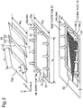
- Fig. 3 is a schematic perspective view illustrating the fluid bag 15 in Fig. 2 .
- each of the first sheet member 15a and the second sheet member 15b is constructed with a sheet member having a substantially rectangular shape in the XY planar view, a dimension in the length direction (X-axis direction) of the second sheet member 15b is longer than a dimension I 0 in the length direction of the first sheet member 15a, and a dimension W1 in the width direction (Y-axis direction) of the second sheet member 15b is longer than a dimension W0 in the width direction of the first sheet member 15a.
- the length directions of the first sheet member 15a and the second sheet member 15b are the X-axis direction
- the width directions of the first sheet member 15a and the second sheet member 15b are the Y-axis direction
- the thickness directions of the first sheet member 15a and the second sheet member 15b are the Z-axis direction.
- the second sheet member 15b is divided in the length direction to form a plurality of expandable pleats 70, and each of the pleat 70 includes an outside pleat 71 located outside and an inside pleat 72 folded inside.
- the outside pleat 71 and the inside pleat 72 are formed by being folded back at a pleat folding line L1 constituting a mountain of the pleat 70 and a pleat folding line L2 constituting a valley.
- the pleat folding line L1 and the pleat folding line L2 are provided such that a dimension a in the length direction of the outside pleat 71 is longer than a dimension b in the length direction of the inside pleat 72 when the pleat 70 is formed.
- the first sheet member 15a and the second sheet member 15b are thermally welded while a corner of the second sheet member 15b is aligned with a corner (welded portion) 21 of the first sheet member 15a indicated by hatching in Fig. 3 .
- a portion where the dimension a in the length direction of the outside pleat 71 of the second sheet member 15b and the dimension b in the length direction of the inside pleat 72 overlap with each other is also thermally welded, the overlapping portion being aligned with the welded portion 21 of the first sheet member 15a.
- a non-welded portion 22 in which the first sheet member 15a and the second sheet member 15b are not thermally welded is provided in order to provide the air supply port 6a.
- the fluid bag 15 having the bag structure is thermally welded onto the base plastic film 12.
- the fluid bag 15 is thermally welded while aligned with a welded portion 31 of the base plastic film 12 indicated by hatching in Fig. 3 .
- a non-welded portion 32 in which the base plastic film 12 and the fluid bag 15 are not thermally welded is provided in order to provide the air supply port 6a.
- the flexible plate 14 is assembled while inserted in a gap formed between the base plastic film 12 and the fluid bag 15.
- Fig. 4A is a perspective view illustrating a structure obtained by a combination of the flexible plate 14 and the fluid bag 15
- Fig. 4B is a longitudinal sectional view taken along line A-A in Fig. 4A
- Fig. 4C is a longitudinal sectional view taken along line B-B in Fig. 4A .
- the rectangular first vinyl chloride plate 14a is attached to prevent a change of a sectional shape of the fluid bag 15, thus preventing the change of the sectional shape and reducing a change in bending rigidity of the fluid bag 15 due to the sectional shape.
- the triangular second vinyl chloride plate 14b is attached to change the bending rigidity of the fluid bag 15.
- an amount of displacement per unit time is increased on the base side of the fluid bag 15 , and the amount of displacement per unit time of the fluid bag 15 can be decreased sequentially toward the leading end side. That is, in the first and second actuators 2, 3, the bending rigidity on the side of the base n is smaller than that on the side of the leading end s. With this configuration, the sides of the bases n of the first and second actuators 2, 3 are bent along the outer peripheral surface of the object, and then the sides of the leading ends s are bent along the outer peripheral surface of the object.
- the same pressure is preferably applied to each of the first and second actuators 2, 3 without pressurizing the first and second actuators 2, 3 in the longitudinal direction a plurality of times. Consequently, pressurization control is easily performed when the first and second actuators 2, 3 are bent.
- Fig. 5 is a schematic diagram illustrating a hydraulic pump 20 that supplies the air as the fluid to the soft gripper 1 in Fig. 1 .
- the hydraulic pump 20 includes a compressor that is of a pressure source, an electropneumatic regulator that adjusts an air pressure to a predetermined pressure value by controlling the air pressure using an electric signal, an electromagnetic valve, and a rubber valve.
- the hydraulic pump 20 can apply an electric signal corresponding to a predetermined pressure to the electropneumatic regulator through a computer, and obtain the air pressure adjusted to a target pressure value in a short time.
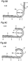
- Figs. 6A to 6C are schematic diagrams illustrating the operation of the soft gripper 1 in Fig. 1 .
- the upper arm 90 that is of the object is placed on the surface, on which the measurement air bag 11 is located, of the soft gripper 1 in the non-pressurized state ( Fig. 6A ).
- the first actuator 2 winds around the upper arm 90 ( Fig. 6B ).
- the second actuator 3 winds around the upper arm 90 ( Fig. 6C ).
- the soft gripper 1 can wind around the upper arm 90. This will be described in more detail below.
- Fig. 7 is a time axis waveform chart illustrating a change in pressure P to time t, the pressure P being applied to the first and second actuators 2, 3 in Fig. 1
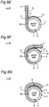
- Figs. 8A to 8G are schematic diagrams illustrating operating states of the first and second actuators 2, 3 at each time t in Fig. 7 .
- Figs. 7 and 8 the pressures applied to the first and second actuator 2, 3 are set to zero at time t1 (non-pressurized).
- the upper arm 90 is placed on the surface of the measurement air bag 11 of the soft gripper 1 (identical to Fig. 6A ).
- a pressure P1 is applied only to the first actuator 2 (the second actuator 3 remains in the non-pressurized state).
- the side of the base n of the first actuator 2 starts to be bent along the outer peripheral surface of the upper arm 90.
- the state in which the pressure PI is applied only to the first actuator 2 is continued (the second actuator 3 remains in the non-pressurized state), and at time t3, the leading end side of the first actuator 2 is bent along the outer peripheral surface of the upper arm 90 subsequent to the base side.
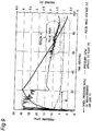
- Fig. 9 is a graph illustrating detection of a pulse wave using the blood pressure measuring cuff in Fig. 1 .
- a peak indicating a pulse wave appears continuously in a region A of around 60 seconds to around 90 seconds, and the blood pressure can be measured based on the peaks. Therefore, it can be understood that the soft gripper 1 can be used as the blood pressure measuring cuff.
- the pressure applied to the pleat 70 is decreased in a section B, this is caused by a leakage of a valve or the like, and the pressure becomes constant after a certain time elapses.
- Fig. 25A is a top view illustrating a flexible plate 14A according to a first modification of the first embodiment of the present invention.
- the flexible plate 14A in Fig. 25A is different from the flexible plate 14 in Fig. 2 in that two triangular second vinyl chloride plates 14Ab are bonded onto the first vinyl chloride plate 14a having the rectangular shape in the XY planar view instead of the triangular second vinyl chloride plate 14b bonded onto the first vinyl chloride plate 14a.
- the two second vinyl chloride plates 14Ab are disposed such that apexes of the triangles are matched with each other at a specific point C between the base n and the leading end s of the flexible plate 14A.
- the first and second actuators 2, 3 can sequentially surround the upper arm 90 from the specific point C toward the side of the leading end s and from the specific point C toward the side of the base n.
- Fig. 25B is a top view illustrating a flexible plate 14B according to a second modification of the first embodiment of the present invention.
- the flexible plate 14B in Fig. 25B is different from the flexible plate 14 in Fig. 2 in that a triangular second vinyl chloride plate 14Bb is bonded onto the first vinyl chloride plate 14a having the rectangular shape in the XY planar view instead of the triangular second vinyl chloride plate 14b bonded onto the first vinyl chloride plate 14a.
- the apex of the triangular second vinyl chloride 14Ab is disposed at the specific point C between the base n and the leading end s of the flexible plate 14B.
- Fig. 26 is a perspective view schematically illustrating a configuration of a soft gripper 1I according to a third modification of the first embodiment of the present invention.
- the soft gripper 1I in Fig. 26 is different from the soft gripper 1 in Fig. 2 in that the side of the leading end s is not divided with respect to the width direction perpendicular to the longitudinal direction in which first and second actuators 2E, 3E extend.
- An air supply port 7a that supplies and discharges the fluid to and from the fluid bag of the first actuator 2E constituting the soft gripper 1I, and an air supply port 8a that supplies and discharges the fluid to and from the fluid bag of the second actuator 3E constituting the soft gripper 1I are provided in the soft gripper 1I of Fig. 26 .
- the first and second actuators 2E, 3E can sequentially surround the object from the side of the base n toward the side of the leading end s.
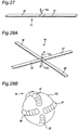
- Fig. 27 is a perspective view schematically illustrating a configuration of a soft gripper 1J according to a fourth modification of the first embodiment of the present invention.
- the soft gripper 1J in Fig. 27 is different from the soft gripper 1I in Fig. 26 in that one air supply port capable of supplying and discharging the fluid to and from each fluid bag is provided.
- the air supply port 7a that supplies and discharges the fluid to and from the fluid bag of the first actuator 2E constituting the soft gripper 1I, and the air supply port 8a that supplies and discharges the fluid to and from the fluid bag of the second actuator 3E constituting the soft gripper 1I are provided in the soft gripper 1I of Fig. 26 .
- one air supply port 11a that supplies and discharges the fluid to and from the fluid bags of the first and second actuators 2F, 3F constituting the soft gripper 1J in Fig. 27 is provided in the soft gripper 1J of Fig. 27 .
- Fig. 28A is a perspective view schematically illustrating a configuration of a soft gripper 1K according to a fifth modification of the first embodiment of the present invention.
- the soft gripper 1K in Fig. 28A is configured such that two soft grippers 1J in Fig. 27 are disposed into a substantially cross shape.
- the Hook-and-Loop fastener is provided on the outer periphery at the leading end of the first actuator, the Hook-and-Loop fastener is provided on the inner periphery at the leading end of the second actuator, and a sphere 92 is surrounded by first and second actuators 2F, 3F. At this point, the Hook-and-Loop fasteners may be fixed while overlapping each other.
- Fig. 28B is a schematic diagram illustrating the operation of the soft gripper 1K in Fig. 28A .
- the fluid is supplied from each air supply port 11a, the fluid is supplied to the fluid bags of the first and second actuators 2F, 3F, and the first and second actuators 2F, 3F are bent along the outer peripheral surface of the sphere 92 to wrap the sphere 92.
- Each of the actuators of the second to fifth modifications may be constructed with a fluid bag 15A according to a third embodiment (to be described later). In that case, the flexible plate 14 may be eliminated. Additionally, the configurations of an opening air bag 30 and a stretching air bag 40 according to a second embodiment (to be described later) may be incorporated.
- Fig. 10 is an exploded perspective view illustrating a structure of a soft gripper 1A according to the second embodiment.
- the soft gripper 1A in Fig. 10 is different from the soft gripper 1 in Fig. 2 in that the opening air bag 30 is attached onto the Hook-and-Loop fastener 13, and that the stretching air bag 40 is attached between the base plastic film 12 and the flexible plate 14. That is, in the second embodiment, the opening air bag 30 that is of a detaching fluid bag, in which the fluid is supplied from the outside to detach these Hook-and-Loop fasteners 5, 13 from each other, is disposed at the positions corresponding to the Hook-and-Loop fasteners 5, 13.
- the stretching air bag 40 which is of a stretching fluid bag in which the fluid is supplied from the outside to eliminate and stretch the bending of the first and second actuators 2, 3, is provided along each surface side, which comes into contact with the upper arm 90, of the first and second actuators 2, 3.
- the fixing between the Hook-and-Loop fastener 5 and the Hook-and-Loop fastener 13 is automatically released by supplying, for example, air as the fluid from the hydraulic pump 20 to the opening air bag 30.
- the fixing between the first and second actuators 2, 3 can automatically be released.
- Stretching speeds of the first and second actuators 2, 3 can be increased by supplying, for example, air as the fluid from the hydraulic pump 20 to the stretching air bag 40. With this configuration, opening times of the first and second actuators 2, 3 can be shortened.
- a tube through which air is supplied from the hydraulic pump 20 to the opening air bag 30 and the stretching air bag 40 may be shared. With this configuration, a size and manufacturing cost of the soft gripper 1A can be reduced.
- Fig. 11 is a schematic diagram illustrating details of the operation of the opening air bag 30 in Fig. 10 .
- Fig. 11A is a schematic diagram illustrating a state immediately before the Hook-and-Loop fastener 5 and the Hook-and-Loop fastener 13 are fixed
- Fig. 11B is a schematic diagram illustrating a state in which the Hook-and-Loop fastener 5 and the Hook-and-Loop fastener 13 are fixed
- Fig. 11C is a schematic diagram illustrating a moment when the air is supplied to the opening air bag 30 to release the fixing between the Hook-and-Loop fastener 5 and the Hook-and-Loop fastener 13.
- Fig. 12 is a time axis waveform chart illustrating the change in pressure P to time t, the pressure P being applied to the first and second actuator 2, 3 in Fig. 1
- Figs. 13A to 13G are schematic diagrams illustrating operating states of the first and the second actuators 2, 3 at each time t in Fig. 12 .
- Figs. 12 and 13A opening operation of the first and second actuators 2, 3 is started at time t10.
- both the pressures applied to the first and second actuators 2, 3 are set to zero, and the pressure P1 is applied to the opening air bag 30 and the stretching air bag 40.
- the leading end side of the second actuator 3 starts to be released from the outer peripheral surface of the upper arm 90 at time t11 as illustrated in Fig. 13B , and the base side of the second actuator 3 is released from the outer peripheral surface of the upper arm 90 at time t12 subsequent to the leading end side as illustrated in Fig. 13C .
- the second actuator 3 is completely opened at time t13.
- the base side of the first actuator 2 is released from the outer peripheral surface of the upper arm 90 subsequent to the leading end side.
- This state is further continued as illustrated in Fig. 13F , and the first and second actuators 2, 3 are completely opened at time t16 as illustrated in Fig. 13G .
- the air is supplied to not only the opening air bag 30 but also the stretching air bag 40, the speed at which the first actuator 2 is released from the outer peripheral surface of the upper arm 90 is enhanced.
- the air is simultaneously supplied from the hydraulic pump 20 to the opening air bag 30 and the stretching air bag 40. With this configuration, the opening speed is further enhanced, so that the first and second actuators 2, 3 can be opened in a short time.
- the air may sequentially be supplied to the opening air bag 30 and the stretching air bag 40.
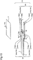
- Fig. 14 is a top view illustrating an appearance of a blood pressure measuring cuff according to the third embodiment of the present invention
- Fig. 15 is an exploded perspective view illustrating a structure of the blood pressure measuring cuff in Fig. 14 .
- the blood pressure measuring cuff in Fig. 14 includes the measurement air bag 11 used to measure the blood pressure and a soft gripper 1B.
- the soft gripper 1B is different from the soft gripper 1 illustrated in Fig. 2 in that the base plastic film 12 and the Hook-and-Loop fasteners 5, 13 are eliminated, that a first actuator 2A is provided instead of the first actuator 2, and that a second actuator 3A is provided instead of the second actuator 3.
- the first actuator 2A includes first bending type actuator units 2Aa, 2Ab instead of the first bending type actuator units 2a, 2b and second bending type actuator units 3Aa, 3Ab instead of the second bending type actuator units 3a, 3b.
- the first bending type actuator units 2Aa, 2Ab and the second bending type actuator units 3Aa, 3Ab are constructed with the fluid bag 15A in which the fluid can be stored.
- the fluid bag 15A has a bag structure including a first sheet member 15Aa, and a second sheet member 15Ab.
- the second sheet members 15Ab is subjected to the folding process called the pleat, when the air pressure is applied to the bag structure, a difference in surface area occurs to generate the bending motion. Details of the fluid bag 15A will be described below with reference to Figs. 16A and 16B .
- the soft gripper 1B has the length of approximately 500 mm in the X-axis direction
- the first actuator 2A has the width of approximately 200 mm in the Y-axis direction
- the second actuator 3A has the width of approximately 80 mm in the Y-axis direction.
- the first and second actuators 2A, 3A extend from the bases n toward opposite sides to each other.
- each of the first and second actuators 2A, 3A sequentially surrounds the object from the side of the base n toward the side of the leading end s of the each of the first and second actuators 2A, 3A.
- the soft gripper 1B is detached from the object, the fluid is exhausted from the first and second actuators 2A, 3A to which the fluid was supplied. Consequently, the bending states of the first and second actuators 2A, 3A, which are bent to surround the object, are eliminated and removed from the object.
- one of the sides of the leading ends s of the first and second actuators 2A, 3A is divided in two portions, and the other side of the leading end s of the first and second actuators 2A, 3A is disposed between the two divided portions.
- the air supply ports 6a, 7a, 8a, 9a are provided in the fluid bags 15A of the first bending type actuator units 2Aa, 2Ab and the second bending type actuator units 3Aa, 3Ab, respectively, such that the fluid can be supplied to and discharged from each of the fluid bags 15A.
- gas such as air
- the fluid is not limited to the air, but liquid such as water may be used.
- the fluid is supplied from the hydraulic pump (see Fig. 5 ) that is of the fluid supply source to the fluid bags 15A connected to the air supply ports 6a, 7a, 8a, 9a through the tubes 6, 7.
- the fluid is simultaneously supplied to the first bending type actuator units 2Aa, 2Ab from the outside such as the hydraulic pump through the air supply ports 6a, 7a to pressurize the first actuator 2A
- the fluid is simultaneously supplied to the second bending type actuator units 3Aa, 3Ab through the air supply ports 8a, 9a to pressurize the second actuator 3A.
- the timing at which the leading end s of the first actuator 2A is bent along the outer peripheral surface of the object and the timing at which the leading end s of the second actuator 3A is bent along the outer peripheral surface of the object.
- the first actuator 2A is sequentially bent from the side of the base n to the side of the leading end s
- the second actuator 3A is sequentially bent from the side of the base n toward the side of the leading end s.
- Fig. 16A is a schematic plan view illustrating the fluid bag 15A in Fig. 15 .
- Fig. 16B is a longitudinal sectional view taken along line A-A in Fig. 16A
- Fig. 16C is a longitudinal sectional view taken along line B-B in Fig. 16A .
- each of the first sheet member 15Aa and the second sheet member 15Ab is constructed with the sheet member having the substantially rectangular shape in the XY planar view, the dimension in the length direction (X-axis direction) of the second sheet member 15Ab is longer than the dimension I 0 in the length direction of the first sheet member 15Aa, and the dimension W1 in the width direction (Y-axis direction) of the second sheet member 15Ab is longer than the dimension W0 in the width direction of the first sheet member 15Aa.
- the length directions of the first sheet member 15Aa and the second sheet member 15Ab are the X-axis direction
- the width directions of the first sheet member 15Aa and the second sheet member 15Ab are the Y-axis direction
- the thickness directions of the first sheet member 15Aa and the second sheet member 15Ab are the Z-axis direction.
- the second sheet member 15Ab is divided in the length direction to form the plurality of expandable pleats 70, and each of the pleat 70 includes the outside pleat 71 located outside and the inside pleat 72 folded inside.
- the outside pleat 71 and the inside pleat 72 are formed by being folded back at a pleat folding line L1 constituting a mountain of the pleat 70 and a pleat folding line L2 constituting a valley.
- the pleat folding line L1 and the pleat folding line L2 are provided such that a dimension a in the length direction of the outside pleat 71 is longer than a dimension b in the length direction of the inside pleat 72 when the pleat 70 is formed.
- the first sheet member 15Aa and the second sheet member 15Ab are thermally welded while the corner of the second sheet member 15Ab is aligned with the corner (welded portion) 21 of the first sheet member 15Aa indicated by hatching in Fig. 16A .
- a portion where the dimension a in the length direction of the outside pleat 71 of the second sheet member 15b and the dimension b in the length direction of the inside pleat 72 overlap with each other is also thermally welded, the overlapping portion being aligned with the welded portion 21 of the first sheet member 15a. Consequently, the fluid can be prevented from leaking out of the fluid chamber to the outside.
- the first sheet member 15Aa and the second sheet member 15Ab are thermally welded while a part of the second sheet member 15Ab is aligned with the welded portion 23 of the first sheet member 15Aa indicated by hatching in Fig. 16A . Consequently, as illustrated in Figs. 16B and 16C , a throttle S that is of a first throttle is provided in the fluid bag 15A at one or a plurality of points in the longitudinal direction of the fluid bag 15A.
- Each of the fluid bags receives the supply of the fluid from the outside through the first or second air supply port. The fluid is supplied from the side of the base toward the side of the leading end through the first throttles provided at one or a plurality of points in the length direction.
- each of the fluid bags is sequentially bent from the base or the specific point toward the side of the leading end in the length direction. It is preferable that the fluid bags are separately pressurized. This enables a time difference of bending to be provided such that the fluid bag 15A is sequentially bent from the base n toward the side of the leading end s with respect to the longitudinal direction of the fluid bag 15A.
- the sides of the bases n of the first and second actuators 2A, 3A are bent along the outer peripheral surface of the object, and then the sides of the leading ends s are bent along the outer peripheral surface of the object.
- the same pressure is preferably applied to each of the first and second actuators 2A, 3A without pressurizing the first and second actuators 2A, 3A in the longitudinal direction a plurality of times. Consequently, the pressurization control is easily performed when the first and second actuators 2A, 3A are bent.
- the fluid bag 15A includes a large-swelling portion and a small-swelling portion along the longitudinal direction. That is, a swelling H2 in Fig. 16C is larger than a swelling H1 in Fig. 16B .
- bending force is large in the large-swelling portion, and bending force is small in the small-swelling portion.
- the large-swelling portion having the large bending force moves similarly to a joint of a human finger
- the small-swelling portion having the small bending force moves similarly to the finger other than the joint.
- the non-welded portion 22 in which the first sheet member 15Aa and the second sheet member 15Ab are not thermally welded is provided in order to provide the air supply port 6a.
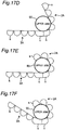
- Figs. 17A to 17I are schematic diagrams illustrating operating states of the first and second actuators 2A, 3A.
- the pressures applied to the first and second actuators 2A, 3A are set to zero (non-pressurized).
- the upper arm 90 is placed on the surface of the measurement air bag 11 of the soft gripper 1B (identical to Fig. 6A ).
- a pressure P1 is applied only to the first actuator 2A (the second actuator 3A remains in the non-pressurized state).
- the side of the base n of the first actuator 2A starts to be bent along the outer peripheral surface of the upper arm 90.
- the side of the base n of the first actuator 2A is bent along the outer peripheral surface of the upper arm 90 as illustrated in Fig. 17C .
- the leading end side of the first actuator 2A is further bent along the outer peripheral surface of the upper arm 90 to wrap the upper arm 90 as illustrated in Fig. 17E (identical to Fig. 6B ).
- the pressure P1 is also applied to the second actuator 3A while the pressure P1 is applied to the first actuator 2A.
- the side of the base n of the second actuator 3A starts to be bent along the outer peripheral surface of the upper arm 90.
- the central portion of the second actuator 3A is bent along the outer peripheral surface of the upper arm 90 subsequent to the base side as illustrated in Fig. 17H .
- the leading end side of the second actuator 3A is further bent along the outer peripheral surface of the upper arm 90 to wrap the upper arm 90 as illustrated in Fig. 17I (identical to Fig. 6C ).
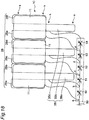
- Fig. 18 is a top view illustrating an appearance of a soft gripper 1C according to a fourth embodiment of the present invention.
- the soft gripper 1B of the third embodiment with respect to the width direction perpendicular to the longitudinal direction in which the first and second actuators 2A, 3A extend, the sides of the leading ends s of the first and second actuators 2A, 3A are divided in two portions, and the second bending type actuator units 3Aa, 3Ab constituting the second actuator 3A are disposed between the two divided portions.
- the side of the leading end s of a first actuator 2B is divided into four portions, and second bending type actuator units 3Ba, 3Bb, 3Bc constituting a second actuator 3B are disposed among the four divided portions.
- the side of the leading end s of the first actuator 2B is constructed with first bending type actuator units 2Ba, 2Bb, 2Bc, 2Bd, 2Be, 2Bf, the first bending type actuator units 2Bb, 2Bc being disposed adjacent to each other, and also the first bending type actuator 2Bd, 2Be being disposed adjacent to each other.
- the operation of the soft gripper 1C having the above configuration will be described below.
- the operation of the soft gripper 1C when the pressures applied to the first and second actuators 2B, 3B using the hydraulic pump 20 in Fig. 5 are set to 15 kPa will be described below.
- a pressurization unit 80 that pressurizes the first and second actuators 2B, 3B in order from one side in an elongated direction of the object is provided at a preceding stage of the first and second actuators 2B, 3B of the soft gripper 1C.
- the pressurization unit 80 includes one flow path through which the fluid is supplied from the outside to its one end (the left end in Fig. 18 ) and throttles 50 to 54 interposed in the portions, which are connected to the first and second actuators 2B, 3B, in the flow path.
- the pressurization unit 80 includes a branch point a that supplies the fluid from the pressure source to the first bending type actuator units 2Ba, 2Bb, a branch point b that supplies the fluid from the pressure source to the second bending type actuator unit 3Ba, a branch point c that supplies the fluid from the pressure source to the first bending type actuator units 2Bc, 2Bd, a branch point d that supplies the fluid from the pressure source to the second bending type actuator unit 3Bb, and a branch point e that supplies the fluid from the pressure source to the first bending type actuator units 2Be, 2Bf.
- the pressurization unit 80 includes the throttle 50 interposed between the branch point a and the branch point b, the throttle 51 interposed between the branch point b and the branch point c, the throttle 52 interposed between the branch point c and the branch point d, the throttle 53 interposed between the branch point d and the branch point e, and the throttle 54 interposed between the branch point e and the second bending type actuator unit 3Bc.
- the fluid is supplied from the hydraulic pump (see Fig. 5 ), which is of the supply source of the fluid, to each fluid bag through the tube 7.
- Fig. 5 The fluid is supplied from the hydraulic pump (see Fig. 5 ), which is of the supply source of the fluid, to each fluid bag through the tube 7.
- the fluid is simultaneously supplied from the hydraulic pump to the first bending type actuator units 2Ba, 2Bb through the branch point a. Consequently, the leading ends s of the first bending type actuator units 2Ba, 2Bb are bent along the outer peripheral surface of the object.
- the fluid passing the throttle 50 is supplied to the second bending type actuator unit 3Ba through the branch point b. Consequently, the second bending type actuator unit 3Ba is bent along the object while being delayed from the first bending type actuator units 2Ba, 2Bb simultaneously bent along the object.
- the fluid passing the throttle 51 is simultaneously supplied to the first bending type actuator units 2Bc, 2Bd through the branch point c. Consequently, the first bending type actuator units 2Bc, 2Bd are simultaneously bent along the object while being delayed from the second bending type actuator unit 3Ba bent along the object.
- the fluid passing the throttle 52 is supplied to the second bending type actuator unit 3Bb through the branch point d. Consequently, the second bending type actuator unit 3Bb is bent along the object while being delayed from the first bending type actuator units 2Bc, 2Bd bent along the object.
- the fluid passing the throttle 53 is simultaneously supplied to the first bending type actuator units 2Be, 2Bf through the branch point e. Consequently, the first bending type actuator units 2Be, 2Bf are simultaneously bent along the object while being delayed from the second bending type actuator unit 3Bb bent along the object.
- the fluid passing the throttle 54 is supplied to the second bending type actuator unit 3Bc. Consequently, the second bending type actuator unit 3Bc is bent along the object while being delayed from the first bending type actuator units 2Be, 2Bf bent along the object, the bending type actuators that are of all the fluid bags surround the object, and the operation is ended.
- This enables the control of the timing at which the leading end s of each fluid bag is bent along the outer peripheral surface of the object. Therefore, the timing of supplying the fluid from the hydraulic pump to each fluid bag can be changed by the simple configuration in which the throttle is interposed in one flow path, such as the tube 7, which passes the fluid.
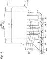
- Fig. 19 is a top view illustrating an appearance of a soft gripper 1D according to a fifth embodiment of the present invention.
- the soft gripper 1B of the third embodiment with respect to the width direction perpendicular to the longitudinal direction in which the first and second actuators 2A, 3A extend, the sides of the leading ends s of the first actuator 2A are divided in two portions, and the second bending type actuator units 3Aa, 3Ab constituting the second actuator 3A are disposed between the two divided portions.
- the side of the leading end s of a first actuator 2C is divided into two portions, and four of second bending type actuator units 3Ca, 3Cb, 3Cc, 3Cd constituting a second actuator 3C are disposed between the two divided portions.
- the operation of the soft gripper 1D having the above configuration will be described below.
- the operation of the soft gripper 1D when the pressures applied to the first and second actuators 2C, 3C using the hydraulic pump 20 in Fig. 5 are set to 15 kPa will be described below.
- a pressurization unit 80A that pressurizes the first and second actuators 2C, 3C in order from one side in the elongated direction of the object is provided at the preceding stage of the first and second actuators 2C, 3C of the soft gripper 1D.
- the pressurization unit 80A includes one flow path through which the fluid is supplied from the outside to its one end (the left end in Fig. 19 ) and throttles 55 to 59 interposed in the portions, which are connected to the first and second actuators 2C, 3C, in the flow path.
- the pressurization unit 80A includes a branch point f that supplies the fluid from the pressure source to the first bending type actuator unit 2Ca, a branch point g that supplies the fluid from the pressure source to the second bending type actuator unit 3Ca, a branch point h that supplies the fluid from the pressure source to the second bending type actuator unit 3Cb, a branch point i that supplies the fluid from the pressure source to the second bending type actuator unit 3Cc, and a branch point j that supplies the fluid from the pressure source to the second bending type actuator unit 3Cd.
- the pressurization unit 80A includes the throttle 55 interposed between the branch point f and the branch point g, the throttle 56 interposed between the branch point g and the branch point h, the throttle 57 interposed between the branch point h and the branch point i, the throttle 58 interposed between the branch point i and the branch point j, and the throttle 59 interposed between the branch point j and the first bending type actuator unit 2Cb.
- the fluid is supplied from the hydraulic pump (see Fig. 5 ), which is of the supply source of the fluid, to each fluid bag through the tube 7.
- Fig. 5 The fluid is supplied from the hydraulic pump (see Fig. 5 ), which is of the supply source of the fluid, to each fluid bag through the tube 7.
- the fluid is supplied from the hydraulic pump to the first bending type actuator unit 2Ca through the branch point f. Consequently, the leading end s of the first bending type actuator unit 2Ca is bent along the outer peripheral surface of the object.
- the fluid passing the throttle 55 is supplied to the second bending type actuator unit 3Ca through the branch point g. Consequently, the second bending type actuator unit 3Ca is bent along the object while being delayed from the first bending type actuator unit 2Ca bent along the object.
- the fluid passing the throttle 56 is supplied to the second bending type actuator unit 3Cb through the branch point h. Consequently, the second bending type actuator unit 3Cb is bent along the object while being delayed from the second bending type actuator unit 3Ca bent along the object.
- the fluid passing the throttle 57 is supplied to the second bending type actuator unit 3Cc through the branch point i. Consequently, the second bending type actuator unit 3Cc is bent along the object while being delayed from the second bending type actuator unit 3Cb bent along the object.
- the fluid passing the throttle 58 is supplied to the second bending type actuator unit 3Cd through the branch point j. Consequently, the second bending type actuator unit 3Cd is bent along the object while being delayed from the second bending type actuator unit 3Cc bent along the object.
- the fluid passing the throttle 59 is supplied to the first bending type actuator unit 2Cb. Consequently, the first bending type actuator unit 2Cb is bent along the object while being delayed from the second bending type actuator unit 3Cd bent along the object, all the fluid bags surround the object, and the operation is ended.
- This enables the control of the timing at which the leading end s of each fluid bag is bent along the outer peripheral surface of the object. Therefore, the timing of supplying the fluid from the hydraulic pump to each fluid bag can be changed by the simple configuration in which the throttle is interposed in one flow path, such as the tube 7, which passes the fluid.
- Fig. 20 is a top view illustrating an appearance of a soft gripper 1E according to a sixth embodiment of the present invention.
- the soft gripper 1B of the third embodiment with respect to the width direction perpendicular to the longitudinal direction in which the first and second actuators 2A, 3A extend, the sides of the leading ends s of the first and second actuators 2A, 3A are divided in two portions, and the second bending type actuator units 3Aa, 3Ab constituting the second actuator 3A are disposed between the two divided portions.
- the side of the leading end s of a first actuator 2D is divided into five portions of second bending type actuator units 2Da, 2Db, 2Dc, 2Dd, 2De, and four of second bending type actuator units 3Da, 3Db, 3Dc and 3Dd constituting a second actuator 3D are disposed among the divided five portions.
- the operation of the soft gripper 1E having the above configuration will be described below.
- the operation of the soft gripper 1E when the pressures applied to the first and second actuators 2D, 3D using the hydraulic pump 20 in Fig. 5 are set to 15 kPa will be described below.
- a pressurization unit 80B that pressurizes the first and second actuators 2D, 3D in order from one side in the elongated direction of the object is provided at the preceding stage of the first and second actuators 2D, 3D of the soft gripper 1E.
- the pressurization unit 80B includes one flow path through which the fluid is supplied from the outside to its one end (the left end in Fig. 20 ) and throttles 60 to 67 interposed in the portions, which are connected to the first and second actuators 2D, 3D, in the flow path.
- the pressurization unit 80B includes a branch point k that supplies the fluid from the pressure source to the first bending type actuator unit 2Da, a branch point 1 that supplies the fluid from the pressure source to the second bending type actuator unit 3Da, a branch point m that supplies the fluid from the pressure source to the first bending type actuator unit 2Db, a branch point n that supplies the fluid from the pressure source to the second bending type actuator unit 3Db, a branch point o that supplies the fluid from the pressure source to the first bending type actuator unit 2Dc, a branch point p that supplies the fluid from the pressure source to the second bending type actuator unit 3Dc, a branch point q that supplies the fluid from the pressure source to the first bending type actuator unit 2Dd, and a branch point r that supplies the fluid from the pressure source to the second bending type actuator unit 3Dd.
- the pressurization unit 80B includes the throttle 60 interposed between the branch point k and the branch point 1, the throttle 61 interposed between the branch point 1 and the branch point m, the throttle 62 interposed between the branch point m and the branch point n, the throttle 63 inserted between the branch point n and the branch point o, the throttle 64 interposed between the branch point o and the branch point p, the throttle 65 interposed between the branch point p and the branch point q, the throttle 66 interposed between the branch point q and the branch point r, and the throttle 67 interposed between the branch point r and the first bending type actuator unit 2De.
- the fluid is supplied from the hydraulic pump (see Fig. 5 ), which is of the supply source of the fluid, to each fluid bag through the tube 7.
- Fig. 5 The fluid is supplied from the hydraulic pump (see Fig. 5 ), which is of the supply source of the fluid, to each fluid bag through the tube 7.
- Fig. 21 is a schematic diagram illustrating the operation of the soft gripper 1E in Fig. 20 .
- Fig. 21 illustrates the operation in which the soft gripper 1E wraps an object 91 long in one direction.
- the fluid is supplied from the hydraulic pump to the first bending type actuator unit 2Da through the branch point k. Consequently, the leading end s of the first bending type actuator unit 2Da is bent along the outer peripheral surface of the object 91.
- the fluid passing the throttle 60 is supplied to the second bending type actuator unit 3Da through the branch point 1. Consequently, the second bending type actuator unit 3Da is bent along the object 91 while being delayed from the first bending type actuator unit 2Da bent along the object 91.
- the fluid passing the throttle 61 is supplied to the first bending type actuator unit 2Db through the branch point m. Consequently, the first bending type actuator unit 2Db is bent along the object 91 while being delayed from the second bending type actuator unit 3Da bent along the object 91.
- the fluid passing the throttle 62 is supplied to the second bending type actuator unit 3Db through the branch point n. Consequently, the second bending type actuator unit 3Db is bent along the object 91 while being delayed from the first bending type actuator unit 2Db bent along the object 91.
- the fluid passing the throttle 63 is supplied to the first bending type actuator unit 2Dc through the branch point o. Consequently, the first bending type actuator unit 2Dc is bent along the object 91 while being delayed from the second bending type actuator unit 3Db bent along the object 91.
- the fluid passing the throttle 64 is supplied to the second bending type actuator unit 3Dc through the branch point p. Consequently, the second bending type actuator unit 3Dc is bent along the object 91 while being delayed from the first bending type actuator unit 2Dc bent along the object 91.
- the fluid passing the throttle 65 is supplied to the first bending type actuator unit 2Dd through the branch point q. Consequently, the first bending type actuator unit 2Dd is bent along the object 91 while being delayed from the second bending type actuator unit 3Dc bent along the object 91.
- the fluid passing the throttle 66 is supplied to the second bending type actuator unit 3Dd through the branch point r. Consequently, the second bending type actuator unit 3Dd is bent along the object 91 while being delayed from the first bending type actuator unit 2Dd bent along the object 91.
- the fluid passing the throttle 67 is supplied to the first bending type actuator unit 2De. Consequently, the first bending type actuator unit 2De is bent along the object 91 while being delayed from the second bending type actuator unit 3Dd bent along the object 91, all the fluid bags surround the object 91, and the operation is ended.
- This enables the control of the timing at which the leading end s of the fluid bag is bent along the outer peripheral surface of the object 91. Therefore, the timing of supplying the fluid from the hydraulic pump to each fluid bag can be changed by the simple configuration in which the throttle is interposed in one flow path, such as the tube 7, which passes the fluid.
- the third to sixth embodiments do not include the configurations of the flexible plate 14 of the first and second embodiments.
- the third to sixth embodiments may further include the configuration of the flexible plate 14 that changes the bending rigidity of the fluid bag. In this case, the bending speed along the object is further enhanced.
- the configurations of the Hook-and-Loop fasteners 5, 13, the opening air bag 30, and the stretching air bag 40 in the first and second embodiments may also be incorporated in the third to sixth embodiments.
- Fig. 22 is a side view illustrating an appearance of a soft gripper 1F according to the seventh embodiment of the present invention.
- the soft gripper 1F in Fig. 22 includes a flexible plate 14A having an elongated shape and a bending type actuator unit 15B that is stuck to the flexible plate 14A so as to overlap the flexible plate 14A.
- the flexible plate 14A in Fig. 22 has the configuration similar to the flexible plate 14 of the first and second embodiments.
- the bending type actuator unit 15B in Fig. 22 has a bag structure similar to that of the bending type actuator unit of the third to sixth embodiments.
- the soft gripper 1F In a natural state before the soft gripper 1F is wound around the object, the soft gripper 1F has a shape in which the soft gripper 1F is bent onto the opposite side to the direction in which the object is surrounded. With this configuration, an apparent dimension (length) in the X direction of the soft gripper 1F can be shortened. Since the size of the soft gripper 1F can be further miniaturized, a volume for storage can further be reduced. Therefore, the storage is facilitated.
- the soft gripper 1F sequentially surrounds the object while releasing the bending. With this configuration, the object can be surrounded even for the narrow space around the soft gripper 1F.
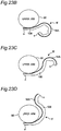
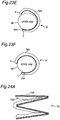
- Figs. 23A-23F are schematic diagrams illustrating the operation of the soft gripper 1F in Fig. 22 .
- Figs. 23A-23F illustrate the operation in which the soft gripper 1F wraps around the upper arm 90.
- the upper arm 90 is placed on the base n on the flexible plate 14A of the soft gripper 1F.
- the leading end s of the soft gripper 1F bent onto the opposite side to the direction in which the upper arm 90 that is of the object is surrounded moves in the direction in which the bending is released (see Fig. 23B ).
- the side of the leading end s of the soft gripper 1F is further bent along the outer peripheral surface to wrap the upper arm 90 as illustrated in Fig. 23F .
- the soft gripper 1F is configured to be bent only once on the opposite side to the direction in which the object is surrounded.
- a soft gripper 1G may be configured to be folded on the opposite side to the direction in which the object is surrounded.
- the soft gripper 1G has the shape in the natural state before the soft gripper 1G is wound around the object.
- a soft gripper 1H may be constructed only with the bending type actuator unit 15B.
- the soft gripper 1H has the shape in the natural state before the soft gripper 1H is wound around the object.
- the operation similar to that of the seventh embodiment can be obtained, and the apparent dimension (length) in the X direction of the soft grippers 1G, 1H can further be shortened. Since the size of the soft grippers 1G, 1H can be further reduced, the volume for storage can further be reduced. Therefore, the storage is further facilitated.
- the configuration of the Hook-and-Loop fasteners 5, 13 of the first embodiment may be incorporated in the end of the soft gripper, or the configurations of the opening air bag 30 and the stretching air bag 40 of the second embodiment may be incorporated.
- the soft grippers 1 to 1K that surround and grip the outer peripheral surface of the upper arm 90, the object 91, or the sphere 92, the soft grippers 1 to 1K include the elongated first actuators 2 to 2F and the elongated second actuators 3 to 3F, which are deformed in response to the supply of the fluid.
- the first actuators 2 to 2F and the second actuators 3 to 3F extend from bases n of the first and second actuators 2 to 2F, 3 to 3F toward opposite sides to each other.
- the first and second actuators 2 to 2F, 3 to 3F sequentially surround the upper arm 90, the object 91, or the sphere 92 in a manner that each of the first and second actuators 2 to 2F, 3 to 3F sequentially surrounds it from the base n or the specific point C between the base n and the leading end s toward the side of the leading end s.
- the first and second actuators 2 to 2F, 3 to 3F when receiving the supply of the fluid, sequentially surround the upper arm 90, the object 91, or the sphere 92 from the bases n of the first and second actuators 2 to 2F, 3 to 3F or the specific point C between the base n and the leading end s toward the side of the leading end s.
- the upper arm 90, the object 91, or the sphere 92 can automatically be surrounded and gripped using the first and second actuators 2 to 2F, 3 to 3F.
- bending rigidity on the side of the base n is smaller than bending rigidity on the side of the leading end s.
- the soft grippers 1 to 1K of the present invention when the same pressure is applied to the first and second actuators 2 to 2F, 3 to 3F, the first and second actuators 2 to 2F, 3 to 3F are bent from the side of the base n toward the side of the leading end s to surround the upper arm 90, the object 91, or the sphere 92. In such a case, the pressurization control is easily performed when the first and second actuators 2 to 2F, 3 to 3F are bent.
- the pressurization would be performed at a plurality of levels in the longitudinal direction of the first and second actuators 2 to 2F, 3 to 3F, making the pressurization control complicated and troublesome.
- each of the first and second actuators 2 to 2F, 3 to 3F includes the flexible plate 14, 14A, 14B and the fluid bag 15 stuck to the flexible plate 14, 14A, 14B
- each of the fluid bags 15 includes a plurality of expandable pleats 70 formed while divided in the length direction
- each of the fluid bags 15 includes the first and second air supply ports 6a, 7a, 8a, 9a that supplies the fluid
- each of the fluid bags 15, 15A, 15B is separately pressurized by receiving the supply of the fluid from the outside through the first or second air supply ports 6a, 7a, 8a, 9a.
- the first and second air supply ports 6a, 7a, 8a, 9a are separately pressurized, the timing at which the leading end s of the first actuators 2 to 2F are bent along the outer peripheral surface of the upper arm 90, the object 91, or the sphere 92 and the timing at which the leading end s of the second actuators 3 to 3F are bent along the outer peripheral surface of the upper arm 90, the object 91, or the sphere 92 can separately be controlled.
- the first actuators 2 to 2F are sequentially bent from the side of the base n to the side of the leading end s
- the second actuators 3 to 3F are sequentially bent from the side of the base n toward the side of the leading end s.
- each of the first and second actuators 2 to 2F, 3 to 3F include the fluid bags 15A, 15B, each of the fluid bags 15A and 15B includes a plurality of expandable pleats 70 that are formed while divided in the length direction and the first throttle S that is provided at one or a plurality of points so as to be sequentially bent from the base n or the specific point C toward the side of the leading end s in the length direction, each of the fluid bags 15A, 15B includes first and second air supply ports 6a, 7a, 8a, 9a that receive the supply of the fluid at the base n, and each of the fluid bags 15A, 15B is pressurized by receiving the supply of the fluid from an outside through the first or second air supply port 6a, 7a, 8a, 9a.
- each of the fluid bags 15A, 15B receives the supply of the fluid from the outside through the first or second air supply ports 6a, 7a, 8a, 9a.
- the fluid is supplied from the side of the base n toward the side of the leading end s through the first throttles S provided at one or a plurality of points in the length direction. Consequently, each of the fluid bags 15A, 15B is sequentially bent from the base n or the specific point C toward the side of the leading end s in the length direction. It is preferable that the fluid bags 15A, 15B are separately pressurized.
- the first actuators 2 to 2F are sequentially bent from the side of the base n to the side of the leading end s
- the second actuators 3 to 3F are sequentially bent from the side of the base n toward the side of the leading end s.
- each of the fluid bags 15A, 15B includes along the length direction, a first portion of large-swelling and a second portion of swelling smaller than that of the first portion.
- the bending force is large in the large-swelling portion and the bending force is small in the small-swelling portion.
- the large-swelling portion having the large bending force moves similarly to a joint of a human finger
- the small-swelling portion having the small bending force moves similarly to the finger other than the joint.
- the soft grippers 1 to 1K of one embodiment includes:
- the soft grippers 1 to 1K of this embodiment when the upper arm 90, the object 91, or the sphere 92 is surrounded by the first and second actuators 2 to 2F, 3 to 3F, the Hook-and-Loop fastener 13 and the Hook-and-Loop fastener 5 are fixed to each other while overlapping each other.
- the upper arm 90 can firmly be fixed with the soft grippers 1 to 1K by receiving the supply of the fluid from the outside.
- the opening air bag 30, which detaches the Hook-and-Loop fasteners 5, 13 from each other by receiving the supply of the fluid from the outside, is disposed at the positions corresponding to the Hook-and-Loop fasteners 5, 13.
- the opening air bag 30 receives the supply of the fluid, whereby the fixing between the Hook-and-Loop fastener 13 and the Hook-and-Loop fastener 5 is automatically released.
- the fixing between the first and second actuators 2 to 2F, 3 to 3F can automatically be released.
- the stretching air bag 40 is provided along each surface side of the first and second actuators 2 to 2F, 3 to 3F which comes into contact with the upper arm 90, the object 91, or the sphere 92, so as to eliminate the bending of the first and second actuators 2 to 2F, 3 to 3F and stretch the first and second actuators 2 to 2F, 3 to 3F when the stretching fluid bag 40 receives the supply of the fluid from the outside.
- the speed at which the first and second actuators 2 to 2F, 3 to 3F are stretched can be enhanced when the stretching air bag 40 receives the supply of the fluid from the outside.
- opening times of the first and second actuators 2 to 2F, 3 to 3F can be shortened.
- one of the sides of the leading ends s of the first and second actuators 2 to 2F, 3 to 3F is divided in two portions, and the other side of the leading end s of the first and second actuators 2 to 2F, 3 to 3F is disposed between the two divided portions.
- the soft grippers 1 to 1K of this embodiment with respect to the width direction perpendicular to the longitudinal direction in which the first and second actuators 2 to 2F, 3 to 3F extend, one of the sides of the leading ends s of the first and second actuators 2 to 2F, 3 to 3F is divided in two portions, and the other side of the leading end s of the first and second actuators 2 to 2F, 3 to 3F is disposed between the two divided portions.
- the soft grippers 1 to 1K wind around the upper arm 90, the object 91, or the sphere 92 without a gap.
- one of the sides of the leading ends s of the first and second actuators 2 to 2F, 3 to 3F is divided in the plurality of portions, and the other side of the leading end s of the first and second actuators 2 to 2F, 3 to 3F is disposed between the plurality of divided portions.
- the soft grippers 1 to 1K of this embodiment with respect to the width direction perpendicular to the longitudinal direction in which the first and second actuators 2 to 2F, 3 to 3F extend, one of the sides of the leading ends s of the first and second actuators 2 to 2F, 3 to 3F is divided in two portions, and the other side of the leading end s of the first and second actuators 2 to 2F, 3 to 3F is disposed between the two divided portions.
- the soft grippers 1 to 1K wind around the upper arm 90, the object 91, or the sphere 92 without a gap.
- the object 91 has an elongated shape in one direction.
- the soft grippers 1 to 1K further include the pressurization unit 80 to 80B that sequentially pressurizes the first and second actuators 2 to 2F, 3 to 3F from one side to the other side in an elongated direction of the object 91.
- the object 91 having the elongated shape can sequentially be wound around from one side to the other side in the elongated direction of the object 91.
- the pressurization units 80 to 80B include one flow path that receives the supply of the fluid from the outside to its one end and the second throttle 50 to 67 interposed between a portion connected to the first actuators 2 to 2F in the flow path and a portion connected to the second actuators 3 to 3F in the flow path.
- the timing of supplying the fluid from the hydraulic pump 20 to each of the fluid bags 15 to 15B can be changed by the simple configuration in which the throttle (second throttles 50 to 67) is interposed in one flow path, such as the tube 7, which passes the fluid.
- the timings at which the plurality of portions of the divided leading ends s of the first and second actuators 2 to 2F, 3 to 3F are bent along the outer peripheral surface of the object 91 can be controlled.
- the first or second actuator 2 to 2F, 3 to 3F in a natural state, has the shape bent or folded on the opposite side to the direction in which the object 91 is surrounded.
- the apparent dimension in the longitudinal direction of the soft grippers 1 to 1K can be shortened. Since the size of the soft grippers 1 to 1K can be further miniaturized, a volume for storage can further be reduced. Therefore, the storage is facilitated.
- the first or second actuator sequentially surrounds the object 91 while releasing the bending or the folding.
- the objects 91 are sequentially surrounded while the bending or the folding is released. With this configuration, the object 91 can be surrounded even for the narrow space around the soft grippers 1 to 1K.
- the blood pressure measuring cuff of the present invention includes the soft grippers 1 to 1K.
- the soft grippers 1 to 1K provided in the blood pressure measuring cuff successively surrounds the upper arm 90 in a manner that each of the first and second actuators 2 to 2F, 3 to 3F sequentially surrounds it from the base n or the specific point C between the base n and the leading end s toward the side of the leading end s.
- the blood pressure measuring cuff on the upper arm 90 even for elderly persons who have difficulties in tightening or removing the blood pressure measuring cuff by themselves or persons having diseases of the shoulder, so that the elderly persons who have difficulties in tightening or detaching the blood pressure measuring cuff by themselves or the persons having the diseases of the shoulder can measure the blood pressure. Since the arm can automatically be wrapped according to a thickness of the arm corresponding to the person who uses the blood pressure measuring cuff, even a person with a thick arm or thin arm can measure the blood pressure.
- the object is assumed to be the arm such as the upper arm, but the object is not limited to the arm.
- the region to be measured may be an upper body, a wrist, or a leg.
- the object is not limited to the human body region to be measured, but may be an object other than the human body.
- the present invention is used for the blood pressure measuring cuff, the present invention is not limited to the blood pressure measuring cuff.
- the present invention can be used for a seatbelt used for vehicles such as a car or an airplane, a rescue robot, an object gripping device that grips soft objects such as a fruit, an amusement playthings such as a crane game machine, an industrial robot used to manufacture a product, a household electric appliance, such as a massage machine, which repeats grasping and releasing operations, and a patient restraint tool that restrains a patient to a bed in a surgical operation or an MRI (Magnetic Resonance Imaging) examination.
- a seatbelt used for vehicles such as a car or an airplane
- a rescue robot an object gripping device that grips soft objects such as a fruit
- an amusement playthings such as a crane game machine
- an industrial robot used to manufacture a product such as a household electric appliance, such as a massage machine, which repeats grasping and releasing operations
Landscapes
- Health & Medical Sciences (AREA)
- Life Sciences & Earth Sciences (AREA)
- Cardiology (AREA)
- Vascular Medicine (AREA)
- Engineering & Computer Science (AREA)
- Heart & Thoracic Surgery (AREA)
- Molecular Biology (AREA)
- Physics & Mathematics (AREA)
- Veterinary Medicine (AREA)
- Biophysics (AREA)
- Pathology (AREA)
- Biomedical Technology (AREA)
- Public Health (AREA)
- Medical Informatics (AREA)
- Physiology (AREA)
- Surgery (AREA)
- Animal Behavior & Ethology (AREA)
- General Health & Medical Sciences (AREA)
- Ophthalmology & Optometry (AREA)
- Dentistry (AREA)
- Robotics (AREA)
- Mechanical Engineering (AREA)
- Measuring Pulse, Heart Rate, Blood Pressure Or Blood Flow (AREA)
- Actuator (AREA)
Abstract
Description
- The present invention relates to a soft gripper, more particularly to a soft gripper that automatically surrounds and grips an object using air pressure. The present invention also relates to a blood pressure measuring cuff provided with the soft gripper.
- In recent years, Japan is approaching a super-aging society. High-blood pressure diseases are cited as injuries and/or diseases with a high rate of treatment accepter for the elderly. Health care by the elderly themselves is regarded as important, and many people use commercially available mobile type sphygmomanometers at home in recent years. For example, Patent Literature 1 (
JP 2013-220321 A - Patent Literature 1:
JP 2013-220321 A - However, it is difficult for the elderly and those having diseases of the shoulder to tighten or detach the blood pressure measuring cuff by themselves. Typically, the elderly and women have a small arm diameter, while in Western countries, sometimes people have an arm diameter large enough not to fix the conventional blood pressure measuring cuff. The thickness of the arm varies by people, and therefore, it was difficult to address these problems.
- An object of the present invention is to provide a soft gripper that can automatically surround and grip the object while adapting to the thickness of the object (including a region to be measured such as the arm). Another object of the present invention is to provide a blood pressure measuring cuff, which includes the soft gripper and can be mounted by automatically surrounding the region to be measured.
- In order to solve the above problem, the soft gripper for fixing a human body of the present invention comprises:
- an elongated first actuator and an elongated second actuator, which are deformed in response to supply of a fluid;
- wherein the first actuator and the second actuator extend from bases of the first and second actuators toward opposite sides to each other, and
- when receiving the supply of the fluid, each of the first and second actuators sequentially surrounds the object from the base or a specific point between the base and a leading end of the each of the first and second actuators toward a side of the leading end.
- As used herein, the "base" means an end on the side of a connection portion where the first actuator and the second actuator are connected to each other. The "leading end" means an end on the opposite side to the "base".
- In the soft gripper of the present invention, when receiving the supply of the fluid, each of the first and second actuators sequentially surrounds the object from the base or a specific point between the base and the leading end toward the side of the leading end.
- Thus, by the soft gripper of this embodiment, it becomes possible to automatically surround and grip the object using the first and second actuators.
- When the soft gripper is detached from the object, the fluid is exhausted from the first and second actuators to which the fluid was supplied. Consequently, the bending states of the first and second actuators, which are bent to surround the object, are eliminated, and the first and second actuators are detached from the object.
- In one embodiment of the soft gripper, in each of the first and second actuators, bending rigidity on a side of the base is smaller than bending rigidity on the side of the leading end.
- In the soft gripper of the present invention, when the same pressure is applied to the first and second actuators, the first and second actuators are bent from the side of the base toward the side of the leading end to surround the object. In such a case, pressurization control is easily performed when the first and second actuators are bent. If the bending rigidity of each of the first and second actuators were uniform in the longitudinal direction, the pressurization would be performed at a plurality of levels in the longitudinal direction of the first and second actuators, making the pressurization control complicated and troublesome.
- In one embodiment of the soft gripper,
each of the first and second actuators includes a flexible plate and a fluid bag stuck to the flexible plate,
each of the fluid bags includes a plurality of expandable pleats that are formed while divided in a length direction,
each of the fluid bags includes first and second air supply ports that supply the fluid, and
each of the fluid bags is separately pressurized by receiving the supply of the fluid from an outside through the first or second air supply port. - As used herein, the "outside" means an outside of the soft gripper.
- In the soft gripper of this embodiment, when the first and second air supply ports are separately pressurized, the timing at which the leading end of the first actuator is bent along the outer peripheral surface of the object and the timing at which the leading end of the second actuator is bent along the outer peripheral surface of the object can separately be controlled. For example, the first actuator is sequentially bent from the side of the base toward the side of the leading end, and then the second actuator is sequentially bent from the side of the base toward the side of the leading end.
- In one embodiment of the soft gripper,
each of the first and second actuators includes a fluid bag,
each of the fluid bags includes a plurality of expandable pleats that are formed while divided in a length direction, and a first throttle that is provided at one or a plurality of points so as to be sequentially bent from the base or the specific point toward the side of the leading end in the length direction,
each of the fluid bags includes first and second air supply ports that receive the supply of the fluid at the base, and
each of the fluid bags is pressurized by receiving the supply of the fluid from an outside through the first or second air supply port. - In the soft gripper of this embodiment, each of the fluid bags receives the supply of the fluid from the outside through the first or second air supply port. The fluid is supplied from the side of the base toward the side of the leading end through the first throttles provided at one or a plurality of points in the length direction. Consequently, each of the fluid bags is sequentially bent from the base or the specific point toward the side of the leading end in the length direction. It is preferable that the fluid bags are separately pressurized. Consequently, it is possible to control timing at which the leading end of the first actuator is bent along an outer peripheral surface of the object, and timing at which the leading end of the second actuator is bent along an outer peripheral surface of the object. For example, the first actuator is sequentially bent from the side of the base toward the side of the leading end, and then the second actuator is sequentially bent from the side of the base toward the side of the leading end.
- In one embodiment of the soft gripper, each of the fluid bags includes along the length direction, a first portion of large-swelling and a second portion of swelling smaller than that of the first portion.
- In the soft gripper of this embodiment, the bending force is large in the large-swelling portion and the bending force is small in the small-swelling portion. With this configuration, the large-swelling portion having the large bending force moves similarly to a joint of a human finger, and the small-swelling portion having the small bending force moves similarly to the finger other than the joint. Thus, it is possible to grip the object like a human hand as a whole.
- One embodiment of the soft gripper comprises:
- a first fixing element provided on an outer periphery at the leading end of the first actuator; and
- a second fixing element provided on an inner periphery at the leading end of the second actuator,
- wherein the first fixing element and the second fixing element are fixed to each other while overlapping each other when the object is surrounded by the first and second actuators.
- In the soft gripper of this embodiment, when the object is surrounded by the first and second actuators, the first fixing element and the second fixing element are fixed to each other while overlapping each other. Thus, the object can firmly be fixed with the soft gripper by receiving the supply of the fluid from the outside.
- In one embodiment of the soft gripper, a detaching fluid bag that receives the supply of the fluid from the outside to detach the first and second fixing elements from each other is disposed at positions corresponding to the first and second fixing elements.
- In the soft gripper of this embodiment, the fixing between the first fixing element and the second fixing element is automatically released when the detaching fluid bag receives the supply of the fluid. Thus, the fixing between the first and second actuators can automatically be released.
- In one embodiment of the soft gripper, a stretching fluid bag is provided along each surface side of the first and second actuators which comes into contact with the object, so as to eliminate the bending of the first and second actuators and stretch the first and second actuators when the stretching fluid bag receives the supply of the fluid from the outside.
- In the soft gripper of this embodiment, the speed at which the first and second actuators are stretched can be enhanced when the stretching fluid bag receives the supply of the fluid from the outside. Thus, opening times of the first and second actuators can be shortened.
- In one embodiment of the soft gripper, with respect to a width direction perpendicular to a longitudinal direction in which the first and second actuators extend, one of the sides of the leading ends of the first and second actuators is divided into two portions, and the other side of the leading end of the first and second actuators is disposed between the two divided portions.
- In the soft gripper of this embodiment, with respect to the width direction perpendicular to the longitudinal direction in which the first and second actuators extend, one of the sides of the leading ends of the first and second actuators is divided in two portions, and the other side of the leading end of the first and second actuators is disposed between the two divided portions. Thus, the soft gripper can wind around the object without a gap when surrounding the object.
- In one embodiment of the soft gripper, with respect to a width direction perpendicular to a longitudinal direction in which the first and second actuators extend, one of the sides of the leading ends of the first and second actuators is divided into a plurality of portions, and the other side of the leading end of the first and second actuators is disposed between the plurality of divided portions.
- In the soft gripper of this embodiment, with respect to the width direction perpendicular to the longitudinal direction in which the first and second actuators extend, one of the sides of the leading ends of the first and second actuators is divided in two portions, and the other side of the leading end of the first and second actuators is disposed between the two divided portions. Thus, the soft gripper can wind around the object without a gap when surrounding the object.
- In one embodiment of the soft gripper,
the object has an elongated shape in one direction,
the soft gripper further comprising:
a pressurization unit that sequentially pressurizes the first and second actuators from one side to the other side in an elongated direction of the object. - In the soft gripper of this embodiment, the object having an elongated shape can sequentially be wound around from one side to the other side in the elongated direction of the object.
- In one embodiment of the soft gripper, the pressurization unit includes one flow path that receives the supply of the fluid from the outside to its one end, and a second throttle interposed between a portion connected to the first actuator in the flow path and a portion connected to the second actuator in the flow path.
- In the soft gripper of this embodiment, the timing of supplying the fluid from the hydraulic pump to each fluid bag can be changed by the simple configuration in which the throttle (second throttle) is interposed in one flow path, such as the tube, which passes the fluid. Thus, the timings at which the plurality of portions of the divided leading ends of the first and second actuators are bent along the outer peripheral surface of the object can be controlled.
- In one embodiment of the soft gripper, in a natural state, the first or second actuator has a shape bent or folded on an opposite side to a direction in which the object is surrounded.
- In the soft gripper of this embodiment, the apparent dimension in the longitudinal direction of the soft gripper can be shortened. Since the size of the soft gripper can be further miniaturized, thus a volume for storage can further be reduced. Therefore, the storage is facilitated.
- In one embodiment of the soft gripper, the first or second actuator sequentially surrounds the object while releasing the bending or the folding.
- The soft gripper of this embodiment sequentially surrounds the object while releasing the bending or the folding. With this configuration, the object can be surrounded even for the narrow space around the soft gripper.
- In another aspect, a blood pressure measuring cuff of the present invention comprises the above described soft gripper.
- In the blood pressure measuring cuff of the present invention, when the first and second actuators receive the supply of the fluid, the soft gripper provided in the blood pressure measuring cuff surrounds the object in a manner that each of the first and second actuators sequentially surrounds it from the base or the specific point between the base and the leading end toward the side of the leading end. Thus, it is possible to automatically mount the blood pressure measuring cuff on the upper arm even for elderly persons who have difficulties in tightening or removing the blood pressure measuring cuff by themselves or persons having diseases of the shoulder, so that they can measure the blood pressure. Since the arm can automatically be wrapped according to a thickness of the arm corresponding to the person who uses the blood pressure measuring cuff, even a person with a thick arm or thin arm can measure the blood pressure.
- As is clear from the above description, in the soft gripper and the blood pressure measuring cuff of the present invention, the object can automatically be surrounded and gripped.
-
-
Fig. 1 is a top view illustrating an appearance of a blood pressure measuring cuff according to a first embodiment of the present invention. -
Fig. 2 is an exploded perspective view illustrating a structure of the blood pressure measuring cuff inFig. 1 . -
Fig. 3 is a schematic perspective view illustrating afluid bag 15 inFig. 2 . -
Fig. 4A is a perspective view illustrating a structure obtained by a combination of aflexible plate 14 and thefluid bag 15. -
Fig. 4B is a longitudinal sectional view taken along line A-A inFig. 4A . -
Fig. 4C is a longitudinal sectional view taken along line B-B inFig. 4A . -
Fig. 5 is a schematic diagram illustrating ahydraulic pump 20 that supplies air as a fluid to thesoft gripper 1 inFig. 1 . -
Fig. 6A is a schematic diagram illustrating a first state of operation of thesoft gripper 1 inFig. 1 . -
Fig. 6B is a schematic diagram illustrating a second state of the operation of thesoft gripper 1 inFig. 1 . -
Fig. 6C is a schematic diagram illustrating a third state of the operation of thesoft gripper 1 inFig. 1 . -
Fig. 7 is a time axis waveform chart illustrating a change in pressure P to time t, the pressure P being applied to afirst actuator 2 and asecond actuator 3 inFig. 1 . -
Fig. 8A is a schematic diagram illustrating operating states of thefirst actuator 2 and thesecond actuator 3 at time t1 inFig. 7 . -
Fig. 8B is a schematic diagram illustrating the operating states of thefirst actuator 2 and thesecond actuator 3 at time t2 inFig. 7 . -
Fig. 8C is a schematic diagram illustrating the operating states of thefirst actuator 2 and thesecond actuator 3 at time t3 inFig. 7 . -
Fig. 8D is a schematic diagram illustrating the operating states of thefirst actuator 2 and thesecond actuator 3 at time t4 inFig. 7 . -
Fig. 8E is a schematic diagram illustrating the operating states of thefirst actuator 2 and thesecond actuator 3 at time t5 inFig. 7 . -
Fig. 8F is a schematic diagram illustrating the operating states of thefirst actuator 2 and thesecond actuator 3 at time t6 inFig. 7 . -
Fig. 8G is a schematic diagram illustrating the operating states of thefirst actuator 2 and thesecond actuator 3 at time t7 inFig. 7 . -
Fig. 9 is a graph illustrating detection of a pulse wave using ameasurement air bag 11 of thesoft gripper 1 inFig. 1 . -
Fig. 10 is an exploded perspective view illustrating a structure of asoft gripper 1A according to a second embodiment. -
Fig. 11A is a schematic diagram illustrating details of operation of an openingair bag 30 inFig. 10 . -
Fig. 11B is a schematic diagram illustrating the details of the operation of the openingair bag 30 inFig. 10 . -
Fig. 11C is a schematic diagram illustrating the details of the operation of the openingair bag 30 inFig. 10 . -
Fig. 12 is a time axis waveform chart illustrating the change in pressure P to time t, the pressure P being applied to thefirst actuator 2 and thesecond actuator 3 inFig. 1 . -
Fig. 13A is a schematic diagram illustrating the operating states of thefirst actuator 2 and thesecond actuator 3 at time t1 inFig. 12 . -
Fig. 13B is a schematic diagram illustrating the operating states of thefirst actuator 2 and thesecond actuator 3 at time t2 inFig. 12 . -
Fig. 13C is a schematic diagram illustrating the operating states of thefirst actuator 2 and thesecond actuator 3 at time t3 inFig. 12 . -
Fig. 13D is a schematic diagram illustrating the operating states of thefirst actuator 2 and thesecond actuator 3 at time t4 inFig. 12 . -
Fig. 13E is a schematic diagram illustrating the operating states of thefirst actuator 2 and thesecond actuator 3 at time t5 inFig. 12 . -
Fig. 13F is a schematic diagram illustrating the operating states of thefirst actuator 2 and thesecond actuator 3 at time t6 inFig. 12 . -
Fig. 13G is a schematic diagram illustrating the operating states of thefirst actuator 2 and thesecond actuator 3 at time t7 inFig. 12 . -
Fig. 14 is a top view illustrating an appearance of a blood pressure measuring cuff according to a third embodiment of the present invention. -
Fig. 15 is an exploded perspective view illustrating the structure of the blood pressure measuring cuff inFig. 14 . -
Fig. 16A is a schematic plan view illustrating afluid bag 15A inFig. 15 . -
Fig. 16B is a longitudinal sectional view taken along line A-A inFig. 16A . -
Fig. 16C is a longitudinal sectional view taken along line B-B inFig. 16A . -
Fig. 17A is a schematic diagram illustrating first operating states of afirst actuator 2A and asecond actuator 3A inFig. 14 . -
Fig. 17B is a schematic diagram illustrating second operating states of thefirst actuator 2A and thesecond actuator 3A inFig. 14 . -
Fig. 17C is a schematic diagram illustrating third operating states of thefirst actuator 2A and thesecond actuator 3A inFig. 14 . -
Fig. 17D is a schematic diagram illustrating fourth operating states of thefirst actuator 2A and thesecond actuator 3A inFig. 14 . -
Fig. 17E is a schematic view illustrating fifth operating states of thefirst actuator 2A and thesecond actuator 3A inFig. 14 . -
Fig. 17F is a schematic diagram illustrating sixth operating states of thefirst actuator 2A and thesecond actuator 3A inFig. 14 . -
Fig. 17G is a schematic diagram illustrating seventh operating states of thefirst actuator 2A and thesecond actuator 3A inFig. 14 . -
Fig. 17H is a schematic diagram illustrating eighth operating states of thefirst actuator 2A and thesecond actuator 3A inFig. 14 . -
Fig. 17I is a schematic diagram illustrating ninth operating states of thefirst actuator 2A and thesecond actuator 3A inFig. 14 . -
Fig. 18 is a top view illustrating an appearance of asoft gripper 1C according to a fourth embodiment of the present invention. -
Fig. 19 is a top view illustrating an appearance of asoft gripper 1D according to a fifth embodiment of the present invention. -
Fig. 20 is a top view illustrating an appearance of asoft gripper 1E according to a sixth embodiment of the present invention. -
Fig. 21 is a schematic diagram illustrating the operation of thesoft gripper 1E inFig. 20 . -
Fig. 22 is a side view illustrating an appearance of asoft gripper 1F according to a seventh embodiment of the present invention. -
Fig. 23A is a schematic diagram illustrating a first state of the operation of thesoft gripper 1F inFig. 22 . -
Fig. 23B is a schematic diagram illustrating a second state of the operation of thesoft gripper 1F inFig. 22 . -
Fig. 23C is a schematic view illustrating a third state of the operation of thesoft gripper 1F inFig. 22 . -
Fig. 23D is a schematic view illustrating a fourth state of the operation of thesoft gripper 1F inFig. 22 . -
Fig. 23E is a schematic view illustrating a fifth state of the operation of thesoft gripper 1F inFig. 22 . -
Fig. 23F is a schematic view illustrating a sixth state of the operation of thesoft gripper 1F inFig. 22 . -
Fig. 24A is a side view illustrating an appearance of asoft gripper 1G according to a first modification of the seventh embodiment of the present invention. -
Fig. 24B is a side view illustrating an appearance of asoft gripper 1H according to a second modification of the seventh embodiment of the present invention. -
Fig. 25A is a top view illustrating aflexible plate 14A according to a first modification of the first embodiment of the present invention. -
Fig. 25B is a top view illustrating aflexible plate 14B according to a second modification of the first embodiment of the present invention. -
Fig. 26 is a perspective view schematically illustrating a configuration of a soft gripper 1I according to a third modification of the first embodiment of the present invention. -
Fig. 27 is a perspective view schematically illustrating a configuration of asoft gripper 1J according to a fourth modification of the first embodiment of the present invention. -
Fig. 28A is a perspective view schematically illustrating a configuration of asoft gripper 1K according to a fifth modification of the first embodiment of the present invention. -
Fig. 28B is a schematic view illustrating the operation of thesoft gripper 1K inFig. 28A . - Hereinafter, embodiments of the present invention will be described with reference to the drawings. In each of the following embodiments, the same components are designated by the same reference numerals, and the description thereof will be omitted.
-
Fig. 1 is a top view illustrating an appearance of a blood pressure measuring cuff according to a first embodiment of the present invention, andFig. 2 is an exploded perspective view illustrating a structure of the blood pressure measuring cuff inFig. 1 . The blood pressure measuring cuff inFig. 1 includes ameasurement air bag 11 used to measure a blood pressure and asoft gripper 1. Thesoft gripper 1 includes an elongatedfirst actuator 2 deformed by receiving supply of fluid, an elongatedsecond actuator 3 deformed by receiving supply of fluid, abase plastic film 12 welding thefirst actuator 2 and thesecond actuator 3, and a Hook-and-Loop fastener 4 that detachably attaches themeasurement air bag 11. - In
Figs. 1 and2 , thefirst actuator 2 includes a first bendingtype actuator unit 2a and a second bendingtype actuator unit 2b, in each of which the fluid can be stored. Thesecond actuator 3 includes a first bendingtype actuator unit 3a and a second bendingtype actuator unit 3b, in each of which the fluid can be stored. Thefirst actuator 2 and thesecond actuator 3 extend from bases n toward opposite sides to each other. When receiving the supply of the fluid, each of the first andsecond actuators second actuators soft gripper 1 is detached from the object, the fluid is exhausted from the first andsecond actuators second actuators second actuators - In the first embodiment, with respect to a width direction perpendicular to a longitudinal direction in which the first and
second actuators second actuators second actuators - Since the
measurement air bag 11 needs to be changed according to a human arm diameter after being wound around anupper arm 90, themeasurement air bag 11 is detachable using the Hook-and-Loop fastener 4. Anair supply port 10a is provided in themeasurement air bag 11 such that the fluid can be supplied and discharged. For example, gas such as air is used as the fluid. However, the fluid is not limited to the air, but liquid such as water may be used. The fluid is supplied from a hydraulic pump (seeFig. 5 ) that is of a fluid supply source to themeasurement air bag 11 through atube 10 connected to theair supply port 10a, and discharged from themeasurement air bag 11 through thetube 10. - A plurality of strip-shaped Hook-and-Loop fasteners are stuck to a front surface side and a back surface side of the
base plastic film 12. In particular, on the side of thefirst actuator 2, a fixing element such as a Hook-and-Loop fastener 13 is stuck onto a back surface side of thebase plastic film 12. That is, the fixing element is provided on an outer periphery of a leading end side of thefirst actuator 2. On the side of thesecond actuator 3, a fixing element such as a Hook-and-Loop fastener 5 in which a plurality of strip-shaped Hook-and-Loop fasteners 5a are arranged is stuck onto a front surface side of thebase plastic film 12. That is, the fixing element is provided on an inner periphery of the leading end s of thesecond actuator 3. When thesoft gripper 1 wraps theupper arm 90, the Hook-and-Loop fastener 13 and the Hook-and-Loop fastener 5 are stuck while overlapping each other, and thesoft gripper 1 is fixed to theupper arm 90. - Each of the first bending
type actuator units type actuator units flexible plate 14 and afluid bag 15, which is stuck to theflexible plate 14 and can store the fluid therein. For example, theflexible plate 14 is made of low density polyethylene (LDPE) or polypropylene (PP). In the first embodiment, theflexible plate 14 is made of vinyl chloride. Theflexible plate 14 is constructed with two plates of a firstvinyl chloride plate 14a having a rectangular shape in an XY planar view and a triangular secondvinyl chloride plate 14b bonded on the firstvinyl chloride plate 14a. Each of the firstvinyl chloride plate 14a and the secondvinyl chloride plate 14b has a thickness of 0.2 mm. - The
fluid bag 15 has a bag structure constructed with afirst sheet member 15a and asecond sheet member 15b. Since thesecond sheet member 15b is subjected to a folding process called a pleat, when an air pressure is applied to the bag structure, a difference in surface area occurs to generate bending motion. Details of thefluid bag 15 will be described below with reference toFigs. 3 and4 . Assuming that a length direction of eachflexible plate 14 is an X-axis direction, that a width direction is a Y-axis direction, and that a thickness direction is a Z-axis direction, thesoft gripper 1 has a length of approximately 500 mm in the X-axis direction, thefirst actuator 2 has a width of approximately 200 mm in the Y-axis direction, and thesecond actuator 3 has a width of approximately 80 mm in the Y-axis direction. -
Air supply ports fluid bags 15 of the first bendingtype actuator units type actuator units fluid bags 15. In the first embodiment, gas such as air is used as the fluid. However, the fluid is not limited to the air, but liquid such as water may be used. The fluid is supplied from the hydraulic pump (seeFig. 5 ) that is of the fluid supply source to thefluid bags 15 connected to theair supply ports tubes type actuator units air supply ports first actuator 2, the fluid is simultaneously supplied to the second bendingtype actuator units air supply ports second actuator 3. Consequently, it is possible to control timing at which the leading end s of thefirst actuator 2 is bent along an outer peripheral surface of the object and timing at which the leading end s of thesecond actuator 3 is bent along an outer peripheral surface of the object. For example, thefirst actuator 2 is sequentially bent from the side of the base n toward the side of the leading end s, and then thesecond actuator 3 is sequentially bent from the side of the base n toward the side of the leading end s. -
Fig. 3 is a schematic perspective view illustrating thefluid bag 15 inFig. 2 . As illustrated inFig. 3 , each of thefirst sheet member 15a and thesecond sheet member 15b is constructed with a sheet member having a substantially rectangular shape in the XY planar view, a dimension in the length direction (X-axis direction) of thesecond sheet member 15b is longer than a dimension I0 in the length direction of thefirst sheet member 15a, and a dimension W1 in the width direction (Y-axis direction) of thesecond sheet member 15b is longer than a dimension W0 in the width direction of thefirst sheet member 15a. At this point, it is assumed that the length directions of thefirst sheet member 15a and thesecond sheet member 15b are the X-axis direction, that the width directions of thefirst sheet member 15a and thesecond sheet member 15b are the Y-axis direction, and that the thickness directions of thefirst sheet member 15a and thesecond sheet member 15b are the Z-axis direction. - As illustrated in
Fig. 3 , thesecond sheet member 15b is divided in the length direction to form a plurality ofexpandable pleats 70, and each of thepleat 70 includes anoutside pleat 71 located outside and aninside pleat 72 folded inside. Theoutside pleat 71 and theinside pleat 72 are formed by being folded back at a pleat folding line L1 constituting a mountain of thepleat 70 and a pleat folding line L2 constituting a valley. The pleat folding line L1 and the pleat folding line L2 are provided such that a dimension a in the length direction of theoutside pleat 71 is longer than a dimension b in the length direction of theinside pleat 72 when thepleat 70 is formed. - When a bag structure is formed using the
first sheet member 15a and thesecond sheet member 15b having different surface areas, in order to form a space (fluid chamber) in which the fluid is stored, thefirst sheet member 15a and thesecond sheet member 15b are thermally welded while a corner of thesecond sheet member 15b is aligned with a corner (welded portion) 21 of thefirst sheet member 15a indicated by hatching inFig. 3 . At this point, a portion where the dimension a in the length direction of theoutside pleat 71 of thesecond sheet member 15b and the dimension b in the length direction of theinside pleat 72 overlap with each other is also thermally welded, the overlapping portion being aligned with the weldedportion 21 of thefirst sheet member 15a. Consequently, the fluid can be prevented from leaking out of the fluid chamber to the outside. InFig. 3 , anon-welded portion 22 in which thefirst sheet member 15a and thesecond sheet member 15b are not thermally welded is provided in order to provide theair supply port 6a. - Then, the
fluid bag 15 having the bag structure is thermally welded onto thebase plastic film 12. In particular, thefluid bag 15 is thermally welded while aligned with a weldedportion 31 of thebase plastic film 12 indicated by hatching inFig. 3 . InFig. 3 , anon-welded portion 32 in which thebase plastic film 12 and thefluid bag 15 are not thermally welded is provided in order to provide theair supply port 6a. Theflexible plate 14 is assembled while inserted in a gap formed between thebase plastic film 12 and thefluid bag 15. -
Fig. 4A is a perspective view illustrating a structure obtained by a combination of theflexible plate 14 and thefluid bag 15,Fig. 4B is a longitudinal sectional view taken along line A-A inFig. 4A, and Fig. 4C is a longitudinal sectional view taken along line B-B inFig. 4A . InFigs. 4A to 4C , the rectangular firstvinyl chloride plate 14a is attached to prevent a change of a sectional shape of thefluid bag 15, thus preventing the change of the sectional shape and reducing a change in bending rigidity of thefluid bag 15 due to the sectional shape. The triangular secondvinyl chloride plate 14b is attached to change the bending rigidity of thefluid bag 15. By setting the A-A side of the sectional view to the base (that is, setting the B-B side of the sectional view to the leading end), an amount of displacement per unit time is increased on the base side of thefluid bag 15 , and the amount of displacement per unit time of thefluid bag 15 can be decreased sequentially toward the leading end side. That is, in the first andsecond actuators second actuators second actuators second actuators second actuators - Operation of the
soft gripper 1 having the above configuration will be described below. -
Fig. 5 is a schematic diagram illustrating ahydraulic pump 20 that supplies the air as the fluid to thesoft gripper 1 inFig. 1 . Thehydraulic pump 20 includes a compressor that is of a pressure source, an electropneumatic regulator that adjusts an air pressure to a predetermined pressure value by controlling the air pressure using an electric signal, an electromagnetic valve, and a rubber valve. Thehydraulic pump 20 can apply an electric signal corresponding to a predetermined pressure to the electropneumatic regulator through a computer, and obtain the air pressure adjusted to a target pressure value in a short time. - The operation of the
soft gripper 1 when the pressures applied to the first andsecond actuators hydraulic pump 20 inFig. 5 are set to 15 kPa will be described below. -
Figs. 6A to 6C are schematic diagrams illustrating the operation of thesoft gripper 1 inFig. 1 . First, theupper arm 90 that is of the object is placed on the surface, on which themeasurement air bag 11 is located, of thesoft gripper 1 in the non-pressurized state (Fig. 6A ). Then, when a pressure of 15 kPa is applied only to thefirst actuator 2, thefirst actuator 2 winds around the upper arm 90 (Fig. 6B ). When a pressure of 15 kPa is also applied to thesecond actuator 3 after thefirst actuator 2 winds around theupper arm 90, thesecond actuator 3 winds around the upper arm 90 (Fig. 6C ). Thus, thesoft gripper 1 can wind around theupper arm 90. This will be described in more detail below. -
Fig. 7 is a time axis waveform chart illustrating a change in pressure P to time t, the pressure P being applied to the first andsecond actuators Fig. 1 , andFigs. 8A to 8G are schematic diagrams illustrating operating states of the first andsecond actuators Fig. 7 . - In
Figs. 7 and8 , the pressures applied to the first andsecond actuator upper arm 90 is placed on the surface of themeasurement air bag 11 of the soft gripper 1 (identical toFig. 6A ). At time t2, a pressure P1 is applied only to the first actuator 2 (thesecond actuator 3 remains in the non-pressurized state). At this point, the side of the base n of thefirst actuator 2 starts to be bent along the outer peripheral surface of theupper arm 90. The state in which the pressure PI is applied only to thefirst actuator 2 is continued (thesecond actuator 3 remains in the non-pressurized state), and at time t3, the leading end side of thefirst actuator 2 is bent along the outer peripheral surface of theupper arm 90 subsequent to the base side. - The state in which the pressure P1 is applied only to the
first actuator 2 is further continued, and at time t4, the leading end side of thefirst actuator 2 is further bent along the outer peripheral surface of theupper arm 90 to wrap the upper arm 90 (identical toFig. 6B ). At time t5, the pressure P1 is also applied to thesecond actuator 3 while thepressure P 1 is applied to thefirst actuator 2. At this point, the side of the base n of thesecond actuator 3 starts to be bent along the outer peripheral surface of theupper arm 90. The state in which the pressure P1 is applied to the first andsecond actuators second actuator 3 is bent along the outer peripheral surface of theupper arm 90 subsequent to the base side. The state is continued, and at time t7, the leading end side of thesecond actuator 3 is further bent along the outer peripheral surface of theupper arm 90 to wrap the upper arm 90 (identical toFig. 6C ). -
Fig. 9 is a graph illustrating detection of a pulse wave using the blood pressure measuring cuff inFig. 1 . As can be seen fromFig. 9 , in the graph of the pulse wave voltage, a peak indicating a pulse wave appears continuously in a region A of around 60 seconds to around 90 seconds, and the blood pressure can be measured based on the peaks. Therefore, it can be understood that thesoft gripper 1 can be used as the blood pressure measuring cuff. Although the pressure applied to thepleat 70 is decreased in a section B, this is caused by a leakage of a valve or the like, and the pressure becomes constant after a certain time elapses. -
Fig. 25A is a top view illustrating aflexible plate 14A according to a first modification of the first embodiment of the present invention. Theflexible plate 14A inFig. 25A is different from theflexible plate 14 inFig. 2 in that two triangular second vinyl chloride plates 14Ab are bonded onto the firstvinyl chloride plate 14a having the rectangular shape in the XY planar view instead of the triangular secondvinyl chloride plate 14b bonded onto the firstvinyl chloride plate 14a. The two second vinyl chloride plates 14Ab are disposed such that apexes of the triangles are matched with each other at a specific point C between the base n and the leading end s of theflexible plate 14A. With this configuration, when receiving the supply of the fluid, the first andsecond actuators upper arm 90 from the specific point C toward the side of the leading end s and from the specific point C toward the side of the base n. -
Fig. 25B is a top view illustrating aflexible plate 14B according to a second modification of the first embodiment of the present invention. Theflexible plate 14B inFig. 25B is different from theflexible plate 14 inFig. 2 in that a triangular second vinyl chloride plate 14Bb is bonded onto the firstvinyl chloride plate 14a having the rectangular shape in the XY planar view instead of the triangular secondvinyl chloride plate 14b bonded onto the firstvinyl chloride plate 14a. In the second vinyl chloride plate 14Bb, the apex of the triangular second vinyl chloride 14Ab is disposed at the specific point C between the base n and the leading end s of theflexible plate 14B. With this configuration, when receiving the fluid supply, the first andsecond actuators upper arm 90 from the specific point C toward the side of the leading end s. -
Fig. 26 is a perspective view schematically illustrating a configuration of a soft gripper 1I according to a third modification of the first embodiment of the present invention. The soft gripper 1I inFig. 26 is different from thesoft gripper 1 inFig. 2 in that the side of the leading end s is not divided with respect to the width direction perpendicular to the longitudinal direction in which first andsecond actuators - An
air supply port 7a that supplies and discharges the fluid to and from the fluid bag of thefirst actuator 2E constituting the soft gripper 1I, and anair supply port 8a that supplies and discharges the fluid to and from the fluid bag of thesecond actuator 3E constituting the soft gripper 1I are provided in the soft gripper 1I ofFig. 26 . - Even in this case, when receiving the fluid supply, the first and
second actuators -
Fig. 27 is a perspective view schematically illustrating a configuration of asoft gripper 1J according to a fourth modification of the first embodiment of the present invention. Thesoft gripper 1J inFig. 27 is different from the soft gripper 1I inFig. 26 in that one air supply port capable of supplying and discharging the fluid to and from each fluid bag is provided. In particular, theair supply port 7a that supplies and discharges the fluid to and from the fluid bag of thefirst actuator 2E constituting the soft gripper 1I, and theair supply port 8a that supplies and discharges the fluid to and from the fluid bag of thesecond actuator 3E constituting the soft gripper 1I are provided in the soft gripper 1I ofFig. 26 . On the other hand, oneair supply port 11a that supplies and discharges the fluid to and from the fluid bags of the first andsecond actuators soft gripper 1J inFig. 27 is provided in thesoft gripper 1J ofFig. 27 . -
Fig. 28A is a perspective view schematically illustrating a configuration of asoft gripper 1K according to a fifth modification of the first embodiment of the present invention. Thesoft gripper 1K inFig. 28A is configured such that twosoft grippers 1J inFig. 27 are disposed into a substantially cross shape. The Hook-and-Loop fastener is provided on the outer periphery at the leading end of the first actuator, the Hook-and-Loop fastener is provided on the inner periphery at the leading end of the second actuator, and asphere 92 is surrounded by first andsecond actuators -
Fig. 28B is a schematic diagram illustrating the operation of thesoft gripper 1K inFig. 28A . As illustrated inFig. 28B , when the fluid is supplied from eachair supply port 11a, the fluid is supplied to the fluid bags of the first andsecond actuators second actuators sphere 92 to wrap thesphere 92. - Each of the actuators of the second to fifth modifications may be constructed with a
fluid bag 15A according to a third embodiment (to be described later). In that case, theflexible plate 14 may be eliminated. Additionally, the configurations of an openingair bag 30 and a stretchingair bag 40 according to a second embodiment (to be described later) may be incorporated. -
Fig. 10 is an exploded perspective view illustrating a structure of asoft gripper 1A according to the second embodiment. Thesoft gripper 1A inFig. 10 is different from thesoft gripper 1 inFig. 2 in that the openingair bag 30 is attached onto the Hook-and-Loop fastener 13, and that the stretchingair bag 40 is attached between thebase plastic film 12 and theflexible plate 14. That is, in the second embodiment, the openingair bag 30 that is of a detaching fluid bag, in which the fluid is supplied from the outside to detach these Hook-and-Loop fasteners Loop fasteners air bag 40, which is of a stretching fluid bag in which the fluid is supplied from the outside to eliminate and stretch the bending of the first andsecond actuators upper arm 90, of the first andsecond actuators - At this point, the fixing between the Hook-and-
Loop fastener 5 and the Hook-and-Loop fastener 13 is automatically released by supplying, for example, air as the fluid from thehydraulic pump 20 to the openingair bag 30. With this configuration, the fixing between the first andsecond actuators - Stretching speeds of the first and
second actuators hydraulic pump 20 to the stretchingair bag 40. With this configuration, opening times of the first andsecond actuators - A tube through which air is supplied from the
hydraulic pump 20 to the openingair bag 30 and the stretchingair bag 40 may be shared. With this configuration, a size and manufacturing cost of thesoft gripper 1A can be reduced. - The operation of the
soft gripper 1A having the above configuration will be described below. -
Fig. 11 is a schematic diagram illustrating details of the operation of the openingair bag 30 inFig. 10 .Fig. 11A is a schematic diagram illustrating a state immediately before the Hook-and-Loop fastener 5 and the Hook-and-Loop fastener 13 are fixed,Fig. 11B is a schematic diagram illustrating a state in which the Hook-and-Loop fastener 5 and the Hook-and-Loop fastener 13 are fixed, andFig. 11C is a schematic diagram illustrating a moment when the air is supplied to the openingair bag 30 to release the fixing between the Hook-and-Loop fastener 5 and the Hook-and-Loop fastener 13. -
Fig. 12 is a time axis waveform chart illustrating the change in pressure P to time t, the pressure P being applied to the first andsecond actuator Fig. 1 , andFigs. 13A to 13G are schematic diagrams illustrating operating states of the first and thesecond actuators Fig. 12 . - In
Figs. 12 and 13A , opening operation of the first andsecond actuators second actuators air bag 30 and the stretchingair bag 40. By continuing this state, the leading end side of thesecond actuator 3 starts to be released from the outer peripheral surface of theupper arm 90 at time t11 as illustrated inFig. 13B , and the base side of thesecond actuator 3 is released from the outer peripheral surface of theupper arm 90 at time t12 subsequent to the leading end side as illustrated inFig. 13C . As illustrated inFig. 13D , thesecond actuator 3 is completely opened at time t13. - As illustrated in
Fig. 13E , at the time t14, at the same time as the leading end side of thefirst actuator 2 is released from the outer peripheral surface of theupper arm 90, the base side of thefirst actuator 2 is released from the outer peripheral surface of theupper arm 90 subsequent to the leading end side. This state is further continued as illustrated inFig. 13F , and the first andsecond actuators Fig. 13G . At this point, since the air is supplied to not only the openingair bag 30 but also the stretchingair bag 40, the speed at which thefirst actuator 2 is released from the outer peripheral surface of theupper arm 90 is enhanced. In the second embodiment, the air is simultaneously supplied from thehydraulic pump 20 to the openingair bag 30 and the stretchingair bag 40. With this configuration, the opening speed is further enhanced, so that the first andsecond actuators air bag 30 and the stretchingair bag 40. -
Fig. 14 is a top view illustrating an appearance of a blood pressure measuring cuff according to the third embodiment of the present invention, andFig. 15 is an exploded perspective view illustrating a structure of the blood pressure measuring cuff inFig. 14 . The blood pressure measuring cuff inFig. 14 includes themeasurement air bag 11 used to measure the blood pressure and asoft gripper 1B. As illustrated inFig. 15 , thesoft gripper 1B is different from thesoft gripper 1 illustrated inFig. 2 in that thebase plastic film 12 and the Hook-and-Loop fasteners first actuator 2A is provided instead of thefirst actuator 2, and that asecond actuator 3A is provided instead of thesecond actuator 3. - As illustrated in
Fig. 15 , compared with thefirst actuator 2 inFig. 2 , thefirst actuator 2A includes first bending type actuator units 2Aa, 2Ab instead of the first bendingtype actuator units type actuator units fluid bag 15A in which the fluid can be stored. Thefluid bag 15A has a bag structure including a first sheet member 15Aa, and a second sheet member 15Ab. Since the second sheet members 15Ab is subjected to the folding process called the pleat, when the air pressure is applied to the bag structure, a difference in surface area occurs to generate the bending motion. Details of thefluid bag 15A will be described below with reference toFigs. 16A and 16B . Assuming that the length direction of each of the actuators 2A, 3A is the X-axis direction, that the width direction is the Y-axis direction, and that the thickness direction is the Z-axis direction, thesoft gripper 1B has the length of approximately 500 mm in the X-axis direction, thefirst actuator 2A has the width of approximately 200 mm in the Y-axis direction, and thesecond actuator 3A has the width of approximately 80 mm in the Y-axis direction. - The first and
second actuators second actuators second actuators soft gripper 1B is detached from the object, the fluid is exhausted from the first andsecond actuators second actuators - In the third embodiment, with respect to the width direction perpendicular to the longitudinal direction in which the first and
second actuators second actuators second actuators - The
air supply ports fluid bags 15A of the first bending type actuator units 2Aa, 2Ab and the second bending type actuator units 3Aa, 3Ab, respectively, such that the fluid can be supplied to and discharged from each of thefluid bags 15A. In the first embodiment, gas such as air is used as the fluid. However, the fluid is not limited to the air, but liquid such as water may be used. The fluid is supplied from the hydraulic pump (seeFig. 5 ) that is of the fluid supply source to thefluid bags 15A connected to theair supply ports tubes air supply ports first actuator 2A, the fluid is simultaneously supplied to the second bending type actuator units 3Aa, 3Ab through theair supply ports second actuator 3A. Consequently, it is possible to control the timing at which the leading end s of thefirst actuator 2A is bent along the outer peripheral surface of the object and the timing at which the leading end s of thesecond actuator 3A is bent along the outer peripheral surface of the object. For example, thefirst actuator 2A is sequentially bent from the side of the base n to the side of the leading end s, and then thesecond actuator 3A is sequentially bent from the side of the base n toward the side of the leading end s. -
Fig. 16A is a schematic plan view illustrating thefluid bag 15A inFig. 15 .Fig. 16B is a longitudinal sectional view taken along line A-A inFig. 16A, and Fig. 16C is a longitudinal sectional view taken along line B-B inFig. 16A . - As illustrated in
Fig. 16A , each of the first sheet member 15Aa and the second sheet member 15Ab is constructed with the sheet member having the substantially rectangular shape in the XY planar view, the dimension in the length direction (X-axis direction) of the second sheet member 15Ab is longer than the dimension I0 in the length direction of the first sheet member 15Aa, and the dimension W1 in the width direction (Y-axis direction) of the second sheet member 15Ab is longer than the dimension W0 in the width direction of the first sheet member 15Aa. At this point, it is assumed that the length directions of the first sheet member 15Aa and the second sheet member 15Ab are the X-axis direction, that the width directions of the first sheet member 15Aa and the second sheet member 15Ab are the Y-axis direction, and that the thickness directions of the first sheet member 15Aa and the second sheet member 15Ab are the Z-axis direction. - As illustrated in
Fig. 16A , the second sheet member 15Ab is divided in the length direction to form the plurality ofexpandable pleats 70, and each of thepleat 70 includes theoutside pleat 71 located outside and theinside pleat 72 folded inside. Theoutside pleat 71 and theinside pleat 72 are formed by being folded back at a pleat folding line L1 constituting a mountain of thepleat 70 and a pleat folding line L2 constituting a valley. The pleat folding line L1 and the pleat folding line L2 are provided such that a dimension a in the length direction of theoutside pleat 71 is longer than a dimension b in the length direction of theinside pleat 72 when thepleat 70 is formed. - When the bag structure is formed using the first sheet member 15Aa and the second sheet member 15Ab having different surface areas, in order to form the space (fluid chamber) in which the fluid is stored, the first sheet member 15Aa and the second sheet member 15Ab are thermally welded while the corner of the second sheet member 15Ab is aligned with the corner (welded portion) 21 of the first sheet member 15Aa indicated by hatching in
Fig. 16A . At this point, a portion where the dimension a in the length direction of theoutside pleat 71 of thesecond sheet member 15b and the dimension b in the length direction of theinside pleat 72 overlap with each other is also thermally welded, the overlapping portion being aligned with the weldedportion 21 of thefirst sheet member 15a. Consequently, the fluid can be prevented from leaking out of the fluid chamber to the outside. - The first sheet member 15Aa and the second sheet member 15Ab are thermally welded while a part of the second sheet member 15Ab is aligned with the welded
portion 23 of the first sheet member 15Aa indicated by hatching inFig. 16A . Consequently, as illustrated inFigs. 16B and 16C , a throttle S that is of a first throttle is provided in thefluid bag 15A at one or a plurality of points in the longitudinal direction of thefluid bag 15A. Each of the fluid bags receives the supply of the fluid from the outside through the first or second air supply port. The fluid is supplied from the side of the base toward the side of the leading end through the first throttles provided at one or a plurality of points in the length direction. Consequently, each of the fluid bags is sequentially bent from the base or the specific point toward the side of the leading end in the length direction. It is preferable that the fluid bags are separately pressurized. This enables a time difference of bending to be provided such that thefluid bag 15A is sequentially bent from the base n toward the side of the leading end s with respect to the longitudinal direction of thefluid bag 15A. With this configuration, the sides of the bases n of the first andsecond actuators second actuators second actuators second actuators - As illustrated in
Figs. 16B and 16C , thefluid bag 15A includes a large-swelling portion and a small-swelling portion along the longitudinal direction. That is, a swelling H2 inFig. 16C is larger than a swelling H1 inFig. 16B . Thus, bending force is large in the large-swelling portion, and bending force is small in the small-swelling portion. With this configuration, the large-swelling portion having the large bending force moves similarly to a joint of a human finger, and the small-swelling portion having the small bending force moves similarly to the finger other than the joint. Thus, it is possible to grip the object like a human hand as a whole. InFig. 16A , thenon-welded portion 22 in which the first sheet member 15Aa and the second sheet member 15Ab are not thermally welded is provided in order to provide theair supply port 6a. - The operation of the
soft gripper 1B having the above configuration will be described below. - The operation of the
soft gripper 1B when the pressures applied to the first andsecond actuators hydraulic pump 20 inFig. 5 are set to 15 kPa will be described below. -
Figs. 17A to 17I are schematic diagrams illustrating operating states of the first andsecond actuators - First, as illustrated in
Fig. 17A , the pressures applied to the first andsecond actuators upper arm 90 is placed on the surface of themeasurement air bag 11 of thesoft gripper 1B (identical toFig. 6A ). - Then, a pressure P1 is applied only to the
first actuator 2A (thesecond actuator 3A remains in the non-pressurized state). At this point, as illustrated inFig. 17B , the side of the base n of thefirst actuator 2A starts to be bent along the outer peripheral surface of theupper arm 90. - When the state in which the pressure P1 is applied only to the
first actuator 2A is continued (thesecond actuator 3A remains in the non-pressurized state), the side of the base n of thefirst actuator 2A is bent along the outer peripheral surface of theupper arm 90 as illustrated inFig. 17C . - When the state in which the pressure P1 is applied only to the
first actuator 2A is further continued (thesecond actuator 3A remains in the non-pressurized state), a central portion of thefirst actuator 2A is bent along the outer peripheral surface of theupper arm 90 as illustrated inFig. 17D . - When the state in which the pressure P1 is applied only to the
first actuator 2A is further continued, the leading end side of thefirst actuator 2A is further bent along the outer peripheral surface of theupper arm 90 to wrap theupper arm 90 as illustrated inFig. 17E (identical toFig. 6B ). - Then, the pressure P1 is also applied to the
second actuator 3A while the pressure P1 is applied to thefirst actuator 2A. At this point, as illustrated inFig. 17F , the side of the base n of thesecond actuator 3A starts to be bent along the outer peripheral surface of theupper arm 90. - When the state in which the pressure P1 is applied to the first and
second actuators second actuator 3A is bent along the outer peripheral surface of theupper arm 90 as illustrated inFig. 17G . - When the state in which the pressure P1 is applied to the first and
second actuators second actuator 3A is bent along the outer peripheral surface of theupper arm 90 subsequent to the base side as illustrated inFig. 17H . When the state is continued, the leading end side of thesecond actuator 3A is further bent along the outer peripheral surface of theupper arm 90 to wrap theupper arm 90 as illustrated inFig. 17I (identical toFig. 6C ). -
Fig. 18 is a top view illustrating an appearance of asoft gripper 1C according to a fourth embodiment of the present invention. In thesoft gripper 1B of the third embodiment, with respect to the width direction perpendicular to the longitudinal direction in which the first andsecond actuators second actuators second actuator 3A are disposed between the two divided portions. On the other hand, in thesoft gripper 1C ofFig. 18 , the side of the leading end s of afirst actuator 2B is divided into four portions, and second bending type actuator units 3Ba, 3Bb, 3Bc constituting asecond actuator 3B are disposed among the four divided portions. At this point, the side of the leading end s of thefirst actuator 2B is constructed with first bending type actuator units 2Ba, 2Bb, 2Bc, 2Bd, 2Be, 2Bf, the first bending type actuator units 2Bb, 2Bc being disposed adjacent to each other, and also the first bending type actuator 2Bd, 2Be being disposed adjacent to each other. - The operation of the
soft gripper 1C having the above configuration will be described below. The operation of thesoft gripper 1C when the pressures applied to the first andsecond actuators hydraulic pump 20 inFig. 5 are set to 15 kPa will be described below. - In the fourth embodiment, as illustrated in
Fig. 18 , in atube 7, apressurization unit 80 that pressurizes the first andsecond actuators second actuators soft gripper 1C. Thepressurization unit 80 includes one flow path through which the fluid is supplied from the outside to its one end (the left end inFig. 18 ) and throttles 50 to 54 interposed in the portions, which are connected to the first andsecond actuators - The
pressurization unit 80 includes a branch point a that supplies the fluid from the pressure source to the first bending type actuator units 2Ba, 2Bb, a branch point b that supplies the fluid from the pressure source to the second bending type actuator unit 3Ba, a branch point c that supplies the fluid from the pressure source to the first bending type actuator units 2Bc, 2Bd, a branch point d that supplies the fluid from the pressure source to the second bending type actuator unit 3Bb, and a branch point e that supplies the fluid from the pressure source to the first bending type actuator units 2Be, 2Bf. - The
pressurization unit 80 includes thethrottle 50 interposed between the branch point a and the branch point b, thethrottle 51 interposed between the branch point b and the branch point c, thethrottle 52 interposed between the branch point c and the branch point d, thethrottle 53 interposed between the branch point d and the branch point e, and thethrottle 54 interposed between the branch point e and the second bending type actuator unit 3Bc. - The fluid is supplied from the hydraulic pump (see
Fig. 5 ), which is of the supply source of the fluid, to each fluid bag through thetube 7. A procedure for bending each bending type actuator unit will be described in detail below. - First, the fluid is simultaneously supplied from the hydraulic pump to the first bending type actuator units 2Ba, 2Bb through the branch point a. Consequently, the leading ends s of the first bending type actuator units 2Ba, 2Bb are bent along the outer peripheral surface of the object.
- Then, the fluid passing the
throttle 50 is supplied to the second bending type actuator unit 3Ba through the branch point b. Consequently, the second bending type actuator unit 3Ba is bent along the object while being delayed from the first bending type actuator units 2Ba, 2Bb simultaneously bent along the object. - Then, the fluid passing the
throttle 51 is simultaneously supplied to the first bending type actuator units 2Bc, 2Bd through the branch point c. Consequently, the first bending type actuator units 2Bc, 2Bd are simultaneously bent along the object while being delayed from the second bending type actuator unit 3Ba bent along the object. - Then, the fluid passing the
throttle 52 is supplied to the second bending type actuator unit 3Bb through the branch point d. Consequently, the second bending type actuator unit 3Bb is bent along the object while being delayed from the first bending type actuator units 2Bc, 2Bd bent along the object. - Then, the fluid passing the
throttle 53 is simultaneously supplied to the first bending type actuator units 2Be, 2Bf through the branch point e. Consequently, the first bending type actuator units 2Be, 2Bf are simultaneously bent along the object while being delayed from the second bending type actuator unit 3Bb bent along the object. - Then, the fluid passing the
throttle 54 is supplied to the second bending type actuator unit 3Bc. Consequently, the second bending type actuator unit 3Bc is bent along the object while being delayed from the first bending type actuator units 2Be, 2Bf bent along the object, the bending type actuators that are of all the fluid bags surround the object, and the operation is ended. This enables the control of the timing at which the leading end s of each fluid bag is bent along the outer peripheral surface of the object. Therefore, the timing of supplying the fluid from the hydraulic pump to each fluid bag can be changed by the simple configuration in which the throttle is interposed in one flow path, such as thetube 7, which passes the fluid. -
Fig. 19 is a top view illustrating an appearance of asoft gripper 1D according to a fifth embodiment of the present invention. In thesoft gripper 1B of the third embodiment, with respect to the width direction perpendicular to the longitudinal direction in which the first andsecond actuators first actuator 2A are divided in two portions, and the second bending type actuator units 3Aa, 3Ab constituting thesecond actuator 3A are disposed between the two divided portions. On the other hand, in thesoft gripper 1D ofFig. 19 , the side of the leading end s of afirst actuator 2C is divided into two portions, and four of second bending type actuator units 3Ca, 3Cb, 3Cc, 3Cd constituting asecond actuator 3C are disposed between the two divided portions. - The operation of the
soft gripper 1D having the above configuration will be described below. The operation of thesoft gripper 1D when the pressures applied to the first andsecond actuators hydraulic pump 20 inFig. 5 are set to 15 kPa will be described below. - In the fifth embodiment, as illustrated in
Fig. 19 , in thetube 7, apressurization unit 80A that pressurizes the first andsecond actuators second actuators soft gripper 1D. Thepressurization unit 80A includes one flow path through which the fluid is supplied from the outside to its one end (the left end inFig. 19 ) and throttles 55 to 59 interposed in the portions, which are connected to the first andsecond actuators - The
pressurization unit 80A includes a branch point f that supplies the fluid from the pressure source to the first bending type actuator unit 2Ca, a branch point g that supplies the fluid from the pressure source to the second bending type actuator unit 3Ca, a branch point h that supplies the fluid from the pressure source to the second bending type actuator unit 3Cb, a branch point i that supplies the fluid from the pressure source to the second bending type actuator unit 3Cc, and a branch point j that supplies the fluid from the pressure source to the second bending type actuator unit 3Cd. - The
pressurization unit 80A includes thethrottle 55 interposed between the branch point f and the branch point g, thethrottle 56 interposed between the branch point g and the branch point h, thethrottle 57 interposed between the branch point h and the branch point i, thethrottle 58 interposed between the branch point i and the branch point j, and thethrottle 59 interposed between the branch point j and the first bending type actuator unit 2Cb. - The fluid is supplied from the hydraulic pump (see
Fig. 5 ), which is of the supply source of the fluid, to each fluid bag through thetube 7. A procedure for bending each bending type actuator unit will be described in detail below. - First, the fluid is supplied from the hydraulic pump to the first bending type actuator unit 2Ca through the branch point f. Consequently, the leading end s of the first bending type actuator unit 2Ca is bent along the outer peripheral surface of the object.
- Then, the fluid passing the
throttle 55 is supplied to the second bending type actuator unit 3Ca through the branch point g. Consequently, the second bending type actuator unit 3Ca is bent along the object while being delayed from the first bending type actuator unit 2Ca bent along the object. - Then, the fluid passing the
throttle 56 is supplied to the second bending type actuator unit 3Cb through the branch point h. Consequently, the second bending type actuator unit 3Cb is bent along the object while being delayed from the second bending type actuator unit 3Ca bent along the object. - Then, the fluid passing the
throttle 57 is supplied to the second bending type actuator unit 3Cc through the branch point i. Consequently, the second bending type actuator unit 3Cc is bent along the object while being delayed from the second bending type actuator unit 3Cb bent along the object. - Then, the fluid passing the
throttle 58 is supplied to the second bending type actuator unit 3Cd through the branch point j. Consequently, the second bending type actuator unit 3Cd is bent along the object while being delayed from the second bending type actuator unit 3Cc bent along the object. - Then, the fluid passing the
throttle 59 is supplied to the first bending type actuator unit 2Cb. Consequently, the first bending type actuator unit 2Cb is bent along the object while being delayed from the second bending type actuator unit 3Cd bent along the object, all the fluid bags surround the object, and the operation is ended. This enables the control of the timing at which the leading end s of each fluid bag is bent along the outer peripheral surface of the object. Therefore, the timing of supplying the fluid from the hydraulic pump to each fluid bag can be changed by the simple configuration in which the throttle is interposed in one flow path, such as thetube 7, which passes the fluid. -
Fig. 20 is a top view illustrating an appearance of asoft gripper 1E according to a sixth embodiment of the present invention. In thesoft gripper 1B of the third embodiment, with respect to the width direction perpendicular to the longitudinal direction in which the first andsecond actuators second actuators second actuator 3A are disposed between the two divided portions. On the other hand, in thesoft gripper 1E ofFig. 20 , the side of the leading end s of afirst actuator 2D is divided into five portions of second bending type actuator units 2Da, 2Db, 2Dc, 2Dd, 2De, and four of second bending type actuator units 3Da, 3Db, 3Dc and 3Dd constituting asecond actuator 3D are disposed among the divided five portions. - The operation of the
soft gripper 1E having the above configuration will be described below. The operation of thesoft gripper 1E when the pressures applied to the first andsecond actuators hydraulic pump 20 inFig. 5 are set to 15 kPa will be described below. - In the sixth embodiment, as illustrated in
Fig. 20 , in thetube 7, apressurization unit 80B that pressurizes the first andsecond actuators second actuators soft gripper 1E. Thepressurization unit 80B includes one flow path through which the fluid is supplied from the outside to its one end (the left end inFig. 20 ) and throttles 60 to 67 interposed in the portions, which are connected to the first andsecond actuators - The
pressurization unit 80B includes a branch point k that supplies the fluid from the pressure source to the first bending type actuator unit 2Da, abranch point 1 that supplies the fluid from the pressure source to the second bending type actuator unit 3Da, a branch point m that supplies the fluid from the pressure source to the first bending type actuator unit 2Db, a branch point n that supplies the fluid from the pressure source to the second bending type actuator unit 3Db, a branch point o that supplies the fluid from the pressure source to the first bending type actuator unit 2Dc, a branch point p that supplies the fluid from the pressure source to the second bending type actuator unit 3Dc, a branch point q that supplies the fluid from the pressure source to the first bending type actuator unit 2Dd, and a branch point r that supplies the fluid from the pressure source to the second bending type actuator unit 3Dd. - The
pressurization unit 80B includes thethrottle 60 interposed between the branch point k and thebranch point 1, thethrottle 61 interposed between thebranch point 1 and the branch point m, thethrottle 62 interposed between the branch point m and the branch point n, thethrottle 63 inserted between the branch point n and the branch point o, thethrottle 64 interposed between the branch point o and the branch point p, thethrottle 65 interposed between the branch point p and the branch point q, thethrottle 66 interposed between the branch point q and the branch point r, and thethrottle 67 interposed between the branch point r and the first bending type actuator unit 2De. - The fluid is supplied from the hydraulic pump (see
Fig. 5 ), which is of the supply source of the fluid, to each fluid bag through thetube 7. A procedure for bending each bending type actuator unit will be described in detail below. -
Fig. 21 is a schematic diagram illustrating the operation of thesoft gripper 1E inFig. 20 .Fig. 21 illustrates the operation in which thesoft gripper 1E wraps anobject 91 long in one direction. - First, the fluid is supplied from the hydraulic pump to the first bending type actuator unit 2Da through the branch point k. Consequently, the leading end s of the first bending type actuator unit 2Da is bent along the outer peripheral surface of the
object 91. - Then, the fluid passing the
throttle 60 is supplied to the second bending type actuator unit 3Da through thebranch point 1. Consequently, the second bending type actuator unit 3Da is bent along theobject 91 while being delayed from the first bending type actuator unit 2Da bent along theobject 91. - Then, the fluid passing the
throttle 61 is supplied to the first bending type actuator unit 2Db through the branch point m. Consequently, the first bending type actuator unit 2Db is bent along theobject 91 while being delayed from the second bending type actuator unit 3Da bent along theobject 91. - Then, the fluid passing the
throttle 62 is supplied to the second bending type actuator unit 3Db through the branch point n. Consequently, the second bending type actuator unit 3Db is bent along theobject 91 while being delayed from the first bending type actuator unit 2Db bent along theobject 91. - Then, the fluid passing the
throttle 63 is supplied to the first bending type actuator unit 2Dc through the branch point o. Consequently, the first bending type actuator unit 2Dc is bent along theobject 91 while being delayed from the second bending type actuator unit 3Db bent along theobject 91. - Then, the fluid passing the
throttle 64 is supplied to the second bending type actuator unit 3Dc through the branch point p. Consequently, the second bending type actuator unit 3Dc is bent along theobject 91 while being delayed from the first bending type actuator unit 2Dc bent along theobject 91. - Then, the fluid passing the
throttle 65 is supplied to the first bending type actuator unit 2Dd through the branch point q. Consequently, the first bending type actuator unit 2Dd is bent along theobject 91 while being delayed from the second bending type actuator unit 3Dc bent along theobject 91. - Then, the fluid passing the
throttle 66 is supplied to the second bending type actuator unit 3Dd through the branch point r. Consequently, the second bending type actuator unit 3Dd is bent along theobject 91 while being delayed from the first bending type actuator unit 2Dd bent along theobject 91. - Then, the fluid passing the
throttle 67 is supplied to the first bending type actuator unit 2De. Consequently, the first bending type actuator unit 2De is bent along theobject 91 while being delayed from the second bending type actuator unit 3Dd bent along theobject 91, all the fluid bags surround theobject 91, and the operation is ended. This enables the control of the timing at which the leading end s of the fluid bag is bent along the outer peripheral surface of theobject 91. Therefore, the timing of supplying the fluid from the hydraulic pump to each fluid bag can be changed by the simple configuration in which the throttle is interposed in one flow path, such as thetube 7, which passes the fluid. - The third to sixth embodiments do not include the configurations of the
flexible plate 14 of the first and second embodiments. However, the third to sixth embodiments may further include the configuration of theflexible plate 14 that changes the bending rigidity of the fluid bag. In this case, the bending speed along the object is further enhanced. - The configurations of the Hook-and-
Loop fasteners air bag 30, and the stretchingair bag 40 in the first and second embodiments may also be incorporated in the third to sixth embodiments. -
Fig. 22 is a side view illustrating an appearance of asoft gripper 1F according to the seventh embodiment of the present invention. Thesoft gripper 1F inFig. 22 includes aflexible plate 14A having an elongated shape and a bendingtype actuator unit 15B that is stuck to theflexible plate 14A so as to overlap theflexible plate 14A. - The
flexible plate 14A inFig. 22 has the configuration similar to theflexible plate 14 of the first and second embodiments. The bendingtype actuator unit 15B inFig. 22 has a bag structure similar to that of the bending type actuator unit of the third to sixth embodiments. - In a natural state before the
soft gripper 1F is wound around the object, thesoft gripper 1F has a shape in which thesoft gripper 1F is bent onto the opposite side to the direction in which the object is surrounded. With this configuration, an apparent dimension (length) in the X direction of thesoft gripper 1F can be shortened. Since the size of thesoft gripper 1F can be further miniaturized, a volume for storage can further be reduced. Therefore, the storage is facilitated. - Additionally, the
soft gripper 1F sequentially surrounds the object while releasing the bending. With this configuration, the object can be surrounded even for the narrow space around thesoft gripper 1F. - The operation of the
soft gripper 1F having the above configuration will be described below. -
Figs. 23A-23F are schematic diagrams illustrating the operation of thesoft gripper 1F inFig. 22 .Figs. 23A-23F illustrate the operation in which thesoft gripper 1F wraps around theupper arm 90. - First, as illustrated in
Fig. 23A , theupper arm 90 is placed on the base n on theflexible plate 14A of thesoft gripper 1F. When the pressure is applied to thesoft gripper 1F, the leading end s of thesoft gripper 1F bent onto the opposite side to the direction in which theupper arm 90 that is of the object is surrounded moves in the direction in which the bending is released (seeFig. 23B ). - When pressure is further applied to the
soft gripper 1F, the bending of thesoft gripper 1F toward the opposite side to theupper arm 90 is further released as illustrated inFig. 23C . - When pressure is further applied to the
soft gripper 1F, the bending of thesoft gripper 1F toward the opposite side to theupper arm 90 is further released as illustrated inFig. 23D , and the side of the leading end s of thesoft gripper 1F moves toward the side of theupper arm 90. - When pressure is further applied to the
soft gripper 1F, the side of the leading end s of thesoft gripper 1F starts to be bent along the outer peripheral surface as illustrated inFig. 23E . - When pressure is further applied to the
soft gripper 1F, the side of the leading end s of thesoft gripper 1F is further bent along the outer peripheral surface to wrap theupper arm 90 as illustrated inFig. 23F . - In the seventh embodiment, the
soft gripper 1F is configured to be bent only once on the opposite side to the direction in which the object is surrounded. In contrast, as illustrated inFig. 24A , asoft gripper 1G may be configured to be folded on the opposite side to the direction in which the object is surrounded. InFig. 24A , thesoft gripper 1G has the shape in the natural state before thesoft gripper 1G is wound around the object. As illustrated inFig. 24B , asoft gripper 1H may be constructed only with the bendingtype actuator unit 15B. InFig. 24B , thesoft gripper 1H has the shape in the natural state before thesoft gripper 1H is wound around the object. Even in these cases, the operation similar to that of the seventh embodiment can be obtained, and the apparent dimension (length) in the X direction of thesoft grippers soft grippers - In the seventh embodiment and its modifications, the configuration of the Hook-and-
Loop fasteners air bag 30 and the stretchingair bag 40 of the second embodiment may be incorporated. - As described above, in the embodiments, the
soft grippers 1 to 1K that surround and grip the outer peripheral surface of theupper arm 90, theobject 91, or thesphere 92, thesoft grippers 1 to 1K include the elongatedfirst actuators 2 to 2F and the elongatedsecond actuators 3 to 3F, which are deformed in response to the supply of the fluid. Thefirst actuators 2 to 2F and thesecond actuators 3 to 3F extend from bases n of the first andsecond actuators 2 to 2F, 3 to 3F toward opposite sides to each other. When receiving the supply of the fluid, the first andsecond actuators 2 to 2F, 3 to 3F sequentially surround theupper arm 90, theobject 91, or thesphere 92 in a manner that each of the first andsecond actuators 2 to 2F, 3 to 3F sequentially surrounds it from the base n or the specific point C between the base n and the leading end s toward the side of the leading end s. - In the
soft grippers 1 to 1K of the present invention, when receiving the supply of the fluid, the first andsecond actuators 2 to 2F, 3 to 3F sequentially surround theupper arm 90, theobject 91, or thesphere 92 from the bases n of the first andsecond actuators 2 to 2F, 3 to 3F or the specific point C between the base n and the leading end s toward the side of the leading end s. - Thus, in the
soft grippers 1 to 1K of this embodiment, theupper arm 90, theobject 91, or thesphere 92 can automatically be surrounded and gripped using the first andsecond actuators 2 to 2F, 3 to 3F. - When the
soft grippers 1 to 1K are detached from theupper arm 90, theobject 91 or thesphere 92, the fluid is exhausted from the first andsecond actuators 2 to 2F, 3 to 3F to which the fluid was supplied. Consequently, the bending states of the first andsecond actuators 2 to 2F, 3 to 3F, which are bent to surround theupper arm 90, theobject 91, or thesphere 92, are eliminated, and the first andsecond actuators 2 to 2F, 3 to 3F are detached from theupper arm 90, theobject 91, or thesphere 92. - In the
soft grippers 1 to 1K of the embodiment, in the first andsecond actuators 2 to 2F, 3 to 3F, bending rigidity on the side of the base n is smaller than bending rigidity on the side of the leading end s. - In the
soft grippers 1 to 1K of the present invention, when the same pressure is applied to the first andsecond actuators 2 to 2F, 3 to 3F, the first andsecond actuators 2 to 2F, 3 to 3F are bent from the side of the base n toward the side of the leading end s to surround theupper arm 90, theobject 91, or thesphere 92. In such a case, the pressurization control is easily performed when the first andsecond actuators 2 to 2F, 3 to 3F are bent. If the bending rigidity of each of the first andsecond actuators 2 to 2F, 3 to 3F were uniform in the longitudinal direction, the pressurization would be performed at a plurality of levels in the longitudinal direction of the first andsecond actuators 2 to 2F, 3 to 3F, making the pressurization control complicated and troublesome. - In the
soft grippers 1 to 1K of one embodiment,
each of the first andsecond actuators 2 to 2F, 3 to 3F includes theflexible plate fluid bag 15 stuck to theflexible plate
each of thefluid bags 15 includes a plurality ofexpandable pleats 70 formed while divided in the length direction,
each of thefluid bags 15 includes the first and secondair supply ports
each of thefluid bags air supply ports - In the
soft grippers 1 to 1K of this embodiment, the first and secondair supply ports first actuators 2 to 2F are bent along the outer peripheral surface of theupper arm 90, theobject 91, or thesphere 92 and the timing at which the leading end s of thesecond actuators 3 to 3F are bent along the outer peripheral surface of theupper arm 90, theobject 91, or thesphere 92 can separately be controlled. For example, thefirst actuators 2 to 2F are sequentially bent from the side of the base n to the side of the leading end s, and then thesecond actuators 3 to 3F are sequentially bent from the side of the base n toward the side of the leading end s. - In the
soft grippers 1 to 1K of one embodiment, each of the first andsecond actuators 2 to 2F, 3 to 3F include thefluid bags
each of thefluid bags expandable pleats 70 that are formed while divided in the length direction and the first throttle S that is provided at one or a plurality of points so as to be sequentially bent from the base n or the specific point C toward the side of the leading end s in the length direction,
each of thefluid bags air supply ports
each of thefluid bags air supply port - In the
soft grippers 1 to 1K of this embodiment, each of thefluid bags air supply ports fluid bags fluid bags first actuators 2 to 2F are bent along the outer peripheral surface of theupper arm 90, theobject 91, or thesphere 92 and the timing at which the leading ends s of thesecond actuators 3 to 3F is bent along the outer peripheral surface of theupper arm 90, theobject 91, or thesphere 92. For example, thefirst actuators 2 to 2F are sequentially bent from the side of the base n to the side of the leading end s, and then thesecond actuators 3 to 3F are sequentially bent from the side of the base n toward the side of the leading end s. - In the
soft grippers 1 to 1K of one embodiment, each of thefluid bags - In the
soft grippers 1 to 1K of this embodiment, the bending force is large in the large-swelling portion and the bending force is small in the small-swelling portion. With this configuration, the large-swelling portion having the large bending force moves similarly to a joint of a human finger, and the small-swelling portion having the small bending force moves similarly to the finger other than the joint. Thus, it is possible to grip the object like a human hand as a whole. - The
soft grippers 1 to 1K of one embodiment includes: - the Hook-and-
Loop fastener 13 provided on the outer periphery of the leading end s of thefirst actuator 2; and - the Hook-and-
Loop fastener 5 provided on the inner periphery of the leading end s of thesecond actuator 3. - When the
upper arm 90 is surrounded by the first andsecond actuators 2 to 2F, 3 to 3F, the Hook-and-Loop fastener 13 and the Hook-and-Loop fastener 5 are fixed to each other while overlapping each other. - In the
soft grippers 1 to 1K of this embodiment, when theupper arm 90, theobject 91, or thesphere 92 is surrounded by the first andsecond actuators 2 to 2F, 3 to 3F, the Hook-and-Loop fastener 13 and the Hook-and-Loop fastener 5 are fixed to each other while overlapping each other. Thus, theupper arm 90 can firmly be fixed with thesoft grippers 1 to 1K by receiving the supply of the fluid from the outside. - In the
soft grippers 1 to 1K of one embodiment, the openingair bag 30, which detaches the Hook-and-Loop fasteners Loop fasteners - In the
soft grippers 1 to 1K of this embodiment, the openingair bag 30 receives the supply of the fluid, whereby the fixing between the Hook-and-Loop fastener 13 and the Hook-and-Loop fastener 5 is automatically released. Thus, the fixing between the first andsecond actuators 2 to 2F, 3 to 3F can automatically be released. - In the
soft grippers 1 to 1K of one embodiment, the stretchingair bag 40 is provided along each surface side of the first andsecond actuators 2 to 2F, 3 to 3F which comes into contact with theupper arm 90, theobject 91, or thesphere 92, so as to eliminate the bending of the first andsecond actuators 2 to 2F, 3 to 3F and stretch the first andsecond actuators 2 to 2F, 3 to 3F when the stretchingfluid bag 40 receives the supply of the fluid from the outside. - In the
soft grippers 1 to 1K of this embodiment, the speed at which the first andsecond actuators 2 to 2F, 3 to 3F are stretched can be enhanced when the stretchingair bag 40 receives the supply of the fluid from the outside. Thus, opening times of the first andsecond actuators 2 to 2F, 3 to 3F can be shortened. - In the
soft grippers 1 to 1K of the embodiment, with respect to the width direction perpendicular to the longitudinal direction in which the first andsecond actuators 2 to 2F, 3 to 3F extend, one of the sides of the leading ends s of the first andsecond actuators 2 to 2F, 3 to 3F is divided in two portions, and the other side of the leading end s of the first andsecond actuators 2 to 2F, 3 to 3F is disposed between the two divided portions. - In the
soft grippers 1 to 1K of this embodiment, with respect to the width direction perpendicular to the longitudinal direction in which the first andsecond actuators 2 to 2F, 3 to 3F extend, one of the sides of the leading ends s of the first andsecond actuators 2 to 2F, 3 to 3F is divided in two portions, and the other side of the leading end s of the first andsecond actuators 2 to 2F, 3 to 3F is disposed between the two divided portions. Thus, when surrounding theupper arm 90, theobject 91, or thesphere 92, thesoft grippers 1 to 1K wind around theupper arm 90, theobject 91, or thesphere 92 without a gap. - In the
soft grippers 1 to 1K of one embodiment,
with respect to the width direction perpendicular to the longitudinal direction in which the first andsecond actuators 2 to 2F, 3 to 3F extend, one of the sides of the leading ends s of the first andsecond actuators 2 to 2F, 3 to 3F is divided in the plurality of portions, and the other side of the leading end s of the first andsecond actuators 2 to 2F, 3 to 3F is disposed between the plurality of divided portions. - In the
soft grippers 1 to 1K of this embodiment, with respect to the width direction perpendicular to the longitudinal direction in which the first andsecond actuators 2 to 2F, 3 to 3F extend, one of the sides of the leading ends s of the first andsecond actuators 2 to 2F, 3 to 3F is divided in two portions, and the other side of the leading end s of the first andsecond actuators 2 to 2F, 3 to 3F is disposed between the two divided portions. Thus, when surrounding theupper arm 90, theobject 91, or thesphere 92, thesoft grippers 1 to 1K wind around theupper arm 90, theobject 91, or thesphere 92 without a gap. - In the
soft grippers 1 to 1K of one embodiment, theobject 91 has an elongated shape in one direction. Thesoft grippers 1 to 1K further include thepressurization unit 80 to 80B that sequentially pressurizes the first andsecond actuators 2 to 2F, 3 to 3F from one side to the other side in an elongated direction of theobject 91. - In the
soft grippers 1 to 1K of this embodiment, theobject 91 having the elongated shape can sequentially be wound around from one side to the other side in the elongated direction of theobject 91. - In the
soft grippers 1 to 1K of one embodiment, thepressurization units 80 to 80B include one flow path that receives the supply of the fluid from the outside to its one end and thesecond throttle 50 to 67 interposed between a portion connected to thefirst actuators 2 to 2F in the flow path and a portion connected to thesecond actuators 3 to 3F in the flow path. - In the
soft grippers 1 to 1K of this embodiment, the timing of supplying the fluid from thehydraulic pump 20 to each of thefluid bags 15 to 15B can be changed by the simple configuration in which the throttle (second throttles 50 to 67) is interposed in one flow path, such as thetube 7, which passes the fluid. Thus, the timings at which the plurality of portions of the divided leading ends s of the first andsecond actuators 2 to 2F, 3 to 3F are bent along the outer peripheral surface of theobject 91 can be controlled. - In the
soft grippers 1 to 1K of one embodiment, in a natural state, the first orsecond actuator 2 to 2F, 3 to 3F has the shape bent or folded on the opposite side to the direction in which theobject 91 is surrounded. - In the
soft grippers 1 to 1K of this embodiment, the apparent dimension in the longitudinal direction of thesoft grippers 1 to 1K can be shortened. Since the size of thesoft grippers 1 to 1K can be further miniaturized, a volume for storage can further be reduced. Therefore, the storage is facilitated. - In the
soft grippers 1 to 1K of one embodiment, the first or second actuator sequentially surrounds theobject 91 while releasing the bending or the folding. - In the
soft grippers 1 to 1K of this embodiment, theobjects 91 are sequentially surrounded while the bending or the folding is released. With this configuration, theobject 91 can be surrounded even for the narrow space around thesoft grippers 1 to 1K. - In another aspect, the blood pressure measuring cuff of the present invention includes the
soft grippers 1 to 1K. - In the blood pressure measuring cuff of the present invention, when the first and
second actuators 2 to 2F, 3 to 3F receive the fluid supply, thesoft grippers 1 to 1K provided in the blood pressure measuring cuff successively surrounds theupper arm 90 in a manner that each of the first andsecond actuators 2 to 2F, 3 to 3F sequentially surrounds it from the base n or the specific point C between the base n and the leading end s toward the side of the leading end s. Thus, it is possible to automatically mount the blood pressure measuring cuff on theupper arm 90 even for elderly persons who have difficulties in tightening or removing the blood pressure measuring cuff by themselves or persons having diseases of the shoulder, so that the elderly persons who have difficulties in tightening or detaching the blood pressure measuring cuff by themselves or the persons having the diseases of the shoulder can measure the blood pressure. Since the arm can automatically be wrapped according to a thickness of the arm corresponding to the person who uses the blood pressure measuring cuff, even a person with a thick arm or thin arm can measure the blood pressure. - In the above embodiments, the object is assumed to be the arm such as the upper arm, but the object is not limited to the arm. The region to be measured may be an upper body, a wrist, or a leg. The object is not limited to the human body region to be measured, but may be an object other than the human body.
- Although the present invention is used for the blood pressure measuring cuff, the present invention is not limited to the blood pressure measuring cuff. For example, the present invention can be used for a seatbelt used for vehicles such as a car or an airplane, a rescue robot, an object gripping device that grips soft objects such as a fruit, an amusement playthings such as a crane game machine, an industrial robot used to manufacture a product, a household electric appliance, such as a massage machine, which repeats grasping and releasing operations, and a patient restraint tool that restrains a patient to a bed in a surgical operation or an MRI (Magnetic Resonance Imaging) examination.
- The above embodiments are only by way of an example, and various modifications can be made without departing from the scope of the present invention.
-
- 1 to 1K
- soft gripper
- 2 to 2F
- first actuator
- 3 to 3F
- second actuator
- 4, 5, 13
- Hook-and-Loop fastener
- 6, 7, 10
- tube
- 11
- measurement air bag
- 12
- base plastic film
- 14
- flexible plate
- 15
- fluid bag
- 90
- upper arm
- 91
- object
- 92
- sphere
Claims (15)
- A soft gripper that surrounds and grips an outer peripheral surface of an object, the soft gripper comprising:an elongated first actuator and an elongated second actuator, which are deformed in response to supply of a fluid;wherein the first actuator and the second actuator extend from bases of the first and second actuators toward opposite sides to each other, andwhen receiving the supply of the fluid, each of the first and second actuators sequentially surrounds the object from the base or a specific point between the base and a leading end of the each of the first and second actuators toward a side of the leading end.
- The soft gripper according to claim 1, wherein
in each of the first and second actuators, bending rigidity on a side of the base is smaller than bending rigidity on the side of the leading end. - The soft gripper according to claim 1 or 2, wherein
each of the first and second actuators includes a flexible plate and a fluid bag stuck to the flexible plate,
each of the fluid bags includes a plurality of expandable pleats that are formed while divided in a length direction,
each of the fluid bags includes first and second air supply ports that supply the fluid, and
each of the fluid bags is separately pressurized by receiving the supply of the fluid from an outside through the first or second air supply port. - The soft gripper according to claim 1 or 2, wherein
each of the first and second actuators includes a fluid bag,
each of the fluid bags includes a plurality of expandable pleats that are formed while divided in a length direction, and a first throttle that is provided at one or a plurality of points so as to be sequentially bent from the base or the specific point toward the side of the leading end in the length direction,
each of the fluid bags includes first and second air supply ports that receive the supply of the fluid at the base, and
each of the fluid bags is pressurized by receiving the supply of the fluid from an outside through the first or second air supply port. - The soft gripper according to claim 4, wherein
each of the fluid bags includes along the length direction, a first portion of large-swelling and a second portion of swelling smaller than that of the first portion. - The soft gripper according to any one of claims 1 to 5, comprising:a first fixing element provided on an outer periphery at the leading end of the first actuator; anda second fixing element provided on an inner periphery at the leading end of the second actuator,wherein the first fixing element and the second fixing element are fixed to each other while overlapping each other when the object is surrounded by the first and second actuators.
- The soft gripper according to claim 6, wherein
a detaching fluid bag that receives the supply of the fluid from the outside to detach the first and second fixing elements from each other is disposed at positions corresponding to the first and second fixing elements. - The soft gripper according to any one of claims 1 to 7, wherein
a stretching fluid bag is provided along each surface side of the first and second actuators which comes into contact with the object, so as to eliminate the bending of the first and second actuators and stretch the first and second actuators when the stretching fluid bag receives the supply of the fluid from the outside. - The soft gripper according to any one of claims 1 to 8, wherein
with respect to a width direction perpendicular to a longitudinal direction in which the first and second actuators extend, one of the sides of the leading ends of the first and second actuators is divided into two portions, and the other side of the leading end of the first and second actuators is disposed between the two divided portions. - The soft gripper according to any one of claims 1 to 8, wherein
with respect to a width direction perpendicular to a longitudinal direction in which the first and second actuators extend, one of the sides of the leading ends of the first and second actuators is divided into a plurality of portions, and the other side of the leading end of the first and second actuators is disposed between the plurality of divided portions. - The soft gripper according to claim 10,
wherein the object has an elongated shape in one direction.
the soft gripper further comprising:
a pressurization unit that sequentially pressurizes the first and second actuators from one side to the other side in an elongated direction of the object. - The soft gripper according to claim 11, wherein
the pressurization unit includes one flow path that receives the supply of the fluid from the outside to its one end, and a second throttle interposed between a portion connected to the first actuator in the flow path and a portion connected to the second actuator in the flow path. - The soft gripper according to any one of claims 1 to 12, wherein
in a natural state, the first or second actuator has a shape bent or folded on an opposite side to a direction in which the object is surrounded. - The soft gripper according to claim 13, wherein
the first or second actuator sequentially surrounds the object while releasing the bending or the folding. - A blood pressure measuring cuff comprising the soft gripper according to any one of claims 1 to 14.
Applications Claiming Priority (2)
| Application Number | Priority Date | Filing Date | Title |
|---|---|---|---|
| JP2015234101 | 2015-11-30 | ||
| PCT/JP2016/066941 WO2017094276A1 (en) | 2015-11-30 | 2016-06-07 | Soft gripper and blood pressure measuring cuff comprising same |
Publications (3)
| Publication Number | Publication Date |
|---|---|
| EP3369372A1 true EP3369372A1 (en) | 2018-09-05 |
| EP3369372A4 EP3369372A4 (en) | 2019-06-26 |
| EP3369372B1 EP3369372B1 (en) | 2024-01-10 |
Family
ID=58796724
Family Applications (1)
| Application Number | Title | Priority Date | Filing Date |
|---|---|---|---|
| EP16870217.3A Active EP3369372B1 (en) | 2015-11-30 | 2016-06-07 | Soft gripper and blood pressure measuring cuff comprising same |
Country Status (5)
| Country | Link |
|---|---|
| US (1) | US10874306B2 (en) |
| EP (1) | EP3369372B1 (en) |
| JP (1) | JP6547007B2 (en) |
| CN (1) | CN108601538B (en) |
| WO (1) | WO2017094276A1 (en) |
Families Citing this family (3)
| Publication number | Priority date | Publication date | Assignee | Title |
|---|---|---|---|---|
| JP7064366B2 (en) | 2018-03-30 | 2022-05-10 | オムロンヘルスケア株式会社 | Cuff unit and sphygmomanometer |
| CN109514542A (en) * | 2018-12-14 | 2019-03-26 | 浙江工业大学 | A kind of flexible manipulator |
| JP7743296B2 (en) * | 2021-12-20 | 2025-09-24 | 株式会社ブリヂストン | gripping device |
Family Cites Families (17)
| Publication number | Priority date | Publication date | Assignee | Title |
|---|---|---|---|---|
| JPS60179038A (en) * | 1984-02-28 | 1985-09-12 | 株式会社富士電機総合研究所 | Automatic cuff winding apparatus for measuring blood pressure |
| US4784042A (en) * | 1986-02-12 | 1988-11-15 | Nathaniel A. Hardin | Method and system employing strings of opposed gaseous-fluid inflatable tension actuators in jointed arms, legs, beams and columns for controlling their movements |
| US5069219A (en) * | 1989-12-20 | 1991-12-03 | Spacelabs, Inc. | Self snugging universal blood pressure cuff |
| JP3235602B2 (en) * | 1999-09-28 | 2001-12-04 | オムロン株式会社 | Biological compression device |
| JP2006198280A (en) * | 2005-01-24 | 2006-08-03 | Matsushita Electric Works Ltd | Sphygmomanometer |
| JP2010110846A (en) * | 2008-11-05 | 2010-05-20 | Panasonic Corp | Robot hand and control device used for the same |
| DE102009039257A1 (en) * | 2009-08-28 | 2011-03-10 | Up Management Gmbh | Blood pressure measuring device and method for measuring the blood pressure of a living being |
| WO2012148472A2 (en) * | 2010-11-19 | 2012-11-01 | President And Fellows Of Harvard College | Soft robotic actuators |
| JP5921225B2 (en) * | 2011-07-20 | 2016-05-24 | 株式会社岩田鉄工所 | Multi-finger hand device |
| JP5910212B2 (en) * | 2012-03-19 | 2016-04-27 | オムロンヘルスケア株式会社 | Blood pressure measurement device |
| JP2013220321A (en) | 2012-04-19 | 2013-10-28 | Omron Healthcare Co Ltd | Blood-pressure measurement apparatus, control device in blood-pressure measurement apparatus and method for controlling blood-pressure measurement apparatus |
| CN202622798U (en) * | 2012-06-04 | 2012-12-26 | 东北林业大学 | Magneto-rheological continuum robot operator |
| US9311792B2 (en) * | 2013-09-27 | 2016-04-12 | Nokia Technologies Oy | Wearable electronic device |
| AU2014329788B2 (en) * | 2013-10-01 | 2020-02-06 | President And Fellows Of Harvard College | Manufacturing soft devices out of sheet materials |
| WO2015138649A1 (en) * | 2014-03-11 | 2015-09-17 | Soft Robotics, Inc. | Soft conformal laparoscopic instrument |
| WO2015138597A1 (en) * | 2014-03-11 | 2015-09-17 | Soft Robotics, Inc. | Soft conformal compression devices and methods |
| CA3175239C (en) * | 2014-09-17 | 2026-03-31 | Schmalz Flexible Gripping Inc. | Soft robotic actuator attachment hub and grasper assembly, reinforced actuators, and electroadhesive actuators |
-
2016
- 2016-06-07 JP JP2017553639A patent/JP6547007B2/en active Active
- 2016-06-07 WO PCT/JP2016/066941 patent/WO2017094276A1/en not_active Ceased
- 2016-06-07 CN CN201680069380.1A patent/CN108601538B/en active Active
- 2016-06-07 EP EP16870217.3A patent/EP3369372B1/en active Active
-
2018
- 2018-05-25 US US15/989,627 patent/US10874306B2/en active Active
Also Published As
| Publication number | Publication date |
|---|---|
| EP3369372B1 (en) | 2024-01-10 |
| CN108601538B (en) | 2021-05-04 |
| EP3369372A4 (en) | 2019-06-26 |
| JPWO2017094276A1 (en) | 2018-11-22 |
| US10874306B2 (en) | 2020-12-29 |
| US20180271386A1 (en) | 2018-09-27 |
| JP6547007B2 (en) | 2019-07-24 |
| WO2017094276A1 (en) | 2017-06-08 |
| CN108601538A (en) | 2018-09-28 |
Similar Documents
| Publication | Publication Date | Title |
|---|---|---|
| US6336901B1 (en) | Sphygmomanometer cuff achieving precise measurement of blood pressure | |
| US6694821B2 (en) | Cuff of wrist-mount blood pressure monitor | |
| JP4742576B2 (en) | Sphygmomanometer cuff and sphygmomanometer equipped with the same | |
| US7637879B2 (en) | Method and apparatus for assisting vascular flow through external compression synchronized with venous phasic flow | |
| EP3369372B1 (en) | Soft gripper and blood pressure measuring cuff comprising same | |
| ATE533413T1 (en) | DEVICE AND METHOD FOR WOUND COMPRESSION | |
| JP2011212159A (en) | Wrist-mount sphymomanometer | |
| JP2006218178A (en) | Cuff for hemadynamometer and hemadynamometer | |
| JP5251447B2 (en) | Cuff for blood pressure information measuring device and blood pressure information measuring device provided with the same | |
| CN102770065B (en) | Cuff for blood pressure information measuring device and blood pressure information measuring device having the cuff | |
| JP2015036041A (en) | Arm site compression device and blood pressure measurement device | |
| WO2019131241A1 (en) | Blood pressure measurement device | |
| JP2010233655A (en) | Sphygmomanometer | |
| JPH0217032A (en) | Cuff winding device of digital electronic hemomanometer for finger | |
| CN211213328U (en) | Compression hemostasis tool | |
| JP6612628B2 (en) | Armband wearing aids and armbands with wearing aids | |
| JP6410506B2 (en) | Breathing apparatus | |
| KR20150142490A (en) | Diagnostic Tester for Pulse of Both Hands | |
| JP3532271B2 (en) | Blood pressure measurement cuff and its fixing device | |
| CN211633822U (en) | An emergency position fixation device | |
| WO2018150749A1 (en) | Cuff for blood pressure information measurement device | |
| KR101646980B1 (en) | Blood pressure measuring apparatus embedding ECG electrode | |
| US12070296B2 (en) | Cuff unit and sphygmomanometer | |
| JP2004065336A (en) | Biological phenomenon measuring apparatus | |
| JP2004159968A (en) | Cuff |
Legal Events
| Date | Code | Title | Description |
|---|---|---|---|
| STAA | Information on the status of an ep patent application or granted ep patent |
Free format text: STATUS: THE INTERNATIONAL PUBLICATION HAS BEEN MADE |
|
| PUAI | Public reference made under article 153(3) epc to a published international application that has entered the european phase |
Free format text: ORIGINAL CODE: 0009012 |
|
| STAA | Information on the status of an ep patent application or granted ep patent |
Free format text: STATUS: REQUEST FOR EXAMINATION WAS MADE |
|
| 17P | Request for examination filed |
Effective date: 20180528 |
|
| AK | Designated contracting states |
Kind code of ref document: A1 Designated state(s): AL AT BE BG CH CY CZ DE DK EE ES FI FR GB GR HR HU IE IS IT LI LT LU LV MC MK MT NL NO PL PT RO RS SE SI SK SM TR |
|
| AX | Request for extension of the european patent |
Extension state: BA ME |
|
| DAV | Request for validation of the european patent (deleted) | ||
| DAX | Request for extension of the european patent (deleted) | ||
| A4 | Supplementary search report drawn up and despatched |
Effective date: 20190523 |
|
| RIC1 | Information provided on ipc code assigned before grant |
Ipc: A61B 5/022 20060101AFI20190517BHEP |
|
| STAA | Information on the status of an ep patent application or granted ep patent |
Free format text: STATUS: EXAMINATION IS IN PROGRESS |
|
| 17Q | First examination report despatched |
Effective date: 20200312 |
|
| REG | Reference to a national code |
Ref country code: DE Ref country code: DE Ref legal event code: R079 Ref document number: 602016085305 Country of ref document: DE Free format text: PREVIOUS MAIN CLASS: A61B0005022000 Ipc: B25J0009140000 |
|
| RIC1 | Information provided on ipc code assigned before grant |
Ipc: A61B 5/022 20060101ALI20230705BHEP Ipc: B25J 9/14 20060101AFI20230705BHEP |
|
| GRAP | Despatch of communication of intention to grant a patent |
Free format text: ORIGINAL CODE: EPIDOSNIGR1 |
|
| STAA | Information on the status of an ep patent application or granted ep patent |
Free format text: STATUS: GRANT OF PATENT IS INTENDED |
|
| INTG | Intention to grant announced |
Effective date: 20230830 |
|
| GRAS | Grant fee paid |
Free format text: ORIGINAL CODE: EPIDOSNIGR3 |
|
| GRAA | (expected) grant |
Free format text: ORIGINAL CODE: 0009210 |
|
| STAA | Information on the status of an ep patent application or granted ep patent |
Free format text: STATUS: THE PATENT HAS BEEN GRANTED |
|
| AK | Designated contracting states |
Kind code of ref document: B1 Designated state(s): AL AT BE BG CH CY CZ DE DK EE ES FI FR GB GR HR HU IE IS IT LI LT LU LV MC MK MT NL NO PL PT RO RS SE SI SK SM TR |
|
| REG | Reference to a national code |
Ref country code: GB Ref legal event code: FG4D |
|
| REG | Reference to a national code |
Ref country code: CH Ref legal event code: EP |
|
| REG | Reference to a national code |
Ref country code: DE Ref legal event code: R096 Ref document number: 602016085305 Country of ref document: DE |
|
| REG | Reference to a national code |
Ref country code: IE Ref legal event code: FG4D |
|
| REG | Reference to a national code |
Ref country code: LT Ref legal event code: MG9D |
|
| REG | Reference to a national code |
Ref country code: NL Ref legal event code: MP Effective date: 20240110 |
|
| REG | Reference to a national code |
Ref country code: AT Ref legal event code: MK05 Ref document number: 1648556 Country of ref document: AT Kind code of ref document: T Effective date: 20240110 |
|
| PG25 | Lapsed in a contracting state [announced via postgrant information from national office to epo] |
Ref country code: NL Free format text: LAPSE BECAUSE OF FAILURE TO SUBMIT A TRANSLATION OF THE DESCRIPTION OR TO PAY THE FEE WITHIN THE PRESCRIBED TIME-LIMIT Effective date: 20240110 |
|
| PG25 | Lapsed in a contracting state [announced via postgrant information from national office to epo] |
Ref country code: NL Free format text: LAPSE BECAUSE OF FAILURE TO SUBMIT A TRANSLATION OF THE DESCRIPTION OR TO PAY THE FEE WITHIN THE PRESCRIBED TIME-LIMIT Effective date: 20240110 |
|
| PG25 | Lapsed in a contracting state [announced via postgrant information from national office to epo] |
Ref country code: IS Free format text: LAPSE BECAUSE OF FAILURE TO SUBMIT A TRANSLATION OF THE DESCRIPTION OR TO PAY THE FEE WITHIN THE PRESCRIBED TIME-LIMIT Effective date: 20240510 |
|
| PG25 | Lapsed in a contracting state [announced via postgrant information from national office to epo] |
Ref country code: LT Free format text: LAPSE BECAUSE OF FAILURE TO SUBMIT A TRANSLATION OF THE DESCRIPTION OR TO PAY THE FEE WITHIN THE PRESCRIBED TIME-LIMIT Effective date: 20240110 |
|
| PG25 | Lapsed in a contracting state [announced via postgrant information from national office to epo] |
Ref country code: GR Free format text: LAPSE BECAUSE OF FAILURE TO SUBMIT A TRANSLATION OF THE DESCRIPTION OR TO PAY THE FEE WITHIN THE PRESCRIBED TIME-LIMIT Effective date: 20240411 |
|
| PG25 | Lapsed in a contracting state [announced via postgrant information from national office to epo] |
Ref country code: RS Free format text: LAPSE BECAUSE OF FAILURE TO SUBMIT A TRANSLATION OF THE DESCRIPTION OR TO PAY THE FEE WITHIN THE PRESCRIBED TIME-LIMIT Effective date: 20240410 Ref country code: HR Free format text: LAPSE BECAUSE OF FAILURE TO SUBMIT A TRANSLATION OF THE DESCRIPTION OR TO PAY THE FEE WITHIN THE PRESCRIBED TIME-LIMIT Effective date: 20240110 |
|
| PG25 | Lapsed in a contracting state [announced via postgrant information from national office to epo] |
Ref country code: ES Free format text: LAPSE BECAUSE OF FAILURE TO SUBMIT A TRANSLATION OF THE DESCRIPTION OR TO PAY THE FEE WITHIN THE PRESCRIBED TIME-LIMIT Effective date: 20240110 |
|
| PG25 | Lapsed in a contracting state [announced via postgrant information from national office to epo] |
Ref country code: AT Free format text: LAPSE BECAUSE OF FAILURE TO SUBMIT A TRANSLATION OF THE DESCRIPTION OR TO PAY THE FEE WITHIN THE PRESCRIBED TIME-LIMIT Effective date: 20240110 |
|
| PG25 | Lapsed in a contracting state [announced via postgrant information from national office to epo] |
Ref country code: RS Free format text: LAPSE BECAUSE OF FAILURE TO SUBMIT A TRANSLATION OF THE DESCRIPTION OR TO PAY THE FEE WITHIN THE PRESCRIBED TIME-LIMIT Effective date: 20240410 Ref country code: NO Free format text: LAPSE BECAUSE OF FAILURE TO SUBMIT A TRANSLATION OF THE DESCRIPTION OR TO PAY THE FEE WITHIN THE PRESCRIBED TIME-LIMIT Effective date: 20240410 Ref country code: LT Free format text: LAPSE BECAUSE OF FAILURE TO SUBMIT A TRANSLATION OF THE DESCRIPTION OR TO PAY THE FEE WITHIN THE PRESCRIBED TIME-LIMIT Effective date: 20240110 Ref country code: IS Free format text: LAPSE BECAUSE OF FAILURE TO SUBMIT A TRANSLATION OF THE DESCRIPTION OR TO PAY THE FEE WITHIN THE PRESCRIBED TIME-LIMIT Effective date: 20240510 Ref country code: HR Free format text: LAPSE BECAUSE OF FAILURE TO SUBMIT A TRANSLATION OF THE DESCRIPTION OR TO PAY THE FEE WITHIN THE PRESCRIBED TIME-LIMIT Effective date: 20240110 Ref country code: GR Free format text: LAPSE BECAUSE OF FAILURE TO SUBMIT A TRANSLATION OF THE DESCRIPTION OR TO PAY THE FEE WITHIN THE PRESCRIBED TIME-LIMIT Effective date: 20240411 Ref country code: ES Free format text: LAPSE BECAUSE OF FAILURE TO SUBMIT A TRANSLATION OF THE DESCRIPTION OR TO PAY THE FEE WITHIN THE PRESCRIBED TIME-LIMIT Effective date: 20240110 Ref country code: BG Free format text: LAPSE BECAUSE OF FAILURE TO SUBMIT A TRANSLATION OF THE DESCRIPTION OR TO PAY THE FEE WITHIN THE PRESCRIBED TIME-LIMIT Effective date: 20240110 Ref country code: AT Free format text: LAPSE BECAUSE OF FAILURE TO SUBMIT A TRANSLATION OF THE DESCRIPTION OR TO PAY THE FEE WITHIN THE PRESCRIBED TIME-LIMIT Effective date: 20240110 |
|
| PG25 | Lapsed in a contracting state [announced via postgrant information from national office to epo] |
Ref country code: PL Free format text: LAPSE BECAUSE OF FAILURE TO SUBMIT A TRANSLATION OF THE DESCRIPTION OR TO PAY THE FEE WITHIN THE PRESCRIBED TIME-LIMIT Effective date: 20240110 Ref country code: PT Free format text: LAPSE BECAUSE OF FAILURE TO SUBMIT A TRANSLATION OF THE DESCRIPTION OR TO PAY THE FEE WITHIN THE PRESCRIBED TIME-LIMIT Effective date: 20240510 |
|
| PG25 | Lapsed in a contracting state [announced via postgrant information from national office to epo] |
Ref country code: SE Free format text: LAPSE BECAUSE OF FAILURE TO SUBMIT A TRANSLATION OF THE DESCRIPTION OR TO PAY THE FEE WITHIN THE PRESCRIBED TIME-LIMIT Effective date: 20240110 Ref country code: PT Free format text: LAPSE BECAUSE OF FAILURE TO SUBMIT A TRANSLATION OF THE DESCRIPTION OR TO PAY THE FEE WITHIN THE PRESCRIBED TIME-LIMIT Effective date: 20240510 Ref country code: PL Free format text: LAPSE BECAUSE OF FAILURE TO SUBMIT A TRANSLATION OF THE DESCRIPTION OR TO PAY THE FEE WITHIN THE PRESCRIBED TIME-LIMIT Effective date: 20240110 Ref country code: LV Free format text: LAPSE BECAUSE OF FAILURE TO SUBMIT A TRANSLATION OF THE DESCRIPTION OR TO PAY THE FEE WITHIN THE PRESCRIBED TIME-LIMIT Effective date: 20240110 |
|
| PG25 | Lapsed in a contracting state [announced via postgrant information from national office to epo] |
Ref country code: DK Free format text: LAPSE BECAUSE OF FAILURE TO SUBMIT A TRANSLATION OF THE DESCRIPTION OR TO PAY THE FEE WITHIN THE PRESCRIBED TIME-LIMIT Effective date: 20240110 |
|
| REG | Reference to a national code |
Ref country code: DE Ref legal event code: R097 Ref document number: 602016085305 Country of ref document: DE |
|
| PG25 | Lapsed in a contracting state [announced via postgrant information from national office to epo] |
Ref country code: SM Free format text: LAPSE BECAUSE OF FAILURE TO SUBMIT A TRANSLATION OF THE DESCRIPTION OR TO PAY THE FEE WITHIN THE PRESCRIBED TIME-LIMIT Effective date: 20240110 |
|
| PG25 | Lapsed in a contracting state [announced via postgrant information from national office to epo] |
Ref country code: CZ Free format text: LAPSE BECAUSE OF FAILURE TO SUBMIT A TRANSLATION OF THE DESCRIPTION OR TO PAY THE FEE WITHIN THE PRESCRIBED TIME-LIMIT Effective date: 20240110 Ref country code: EE Free format text: LAPSE BECAUSE OF FAILURE TO SUBMIT A TRANSLATION OF THE DESCRIPTION OR TO PAY THE FEE WITHIN THE PRESCRIBED TIME-LIMIT Effective date: 20240110 |
|
| PG25 | Lapsed in a contracting state [announced via postgrant information from national office to epo] |
Ref country code: SK Free format text: LAPSE BECAUSE OF FAILURE TO SUBMIT A TRANSLATION OF THE DESCRIPTION OR TO PAY THE FEE WITHIN THE PRESCRIBED TIME-LIMIT Effective date: 20240110 |
|
| PG25 | Lapsed in a contracting state [announced via postgrant information from national office to epo] |
Ref country code: SM Free format text: LAPSE BECAUSE OF FAILURE TO SUBMIT A TRANSLATION OF THE DESCRIPTION OR TO PAY THE FEE WITHIN THE PRESCRIBED TIME-LIMIT Effective date: 20240110 Ref country code: SK Free format text: LAPSE BECAUSE OF FAILURE TO SUBMIT A TRANSLATION OF THE DESCRIPTION OR TO PAY THE FEE WITHIN THE PRESCRIBED TIME-LIMIT Effective date: 20240110 Ref country code: RO Free format text: LAPSE BECAUSE OF FAILURE TO SUBMIT A TRANSLATION OF THE DESCRIPTION OR TO PAY THE FEE WITHIN THE PRESCRIBED TIME-LIMIT Effective date: 20240110 Ref country code: EE Free format text: LAPSE BECAUSE OF FAILURE TO SUBMIT A TRANSLATION OF THE DESCRIPTION OR TO PAY THE FEE WITHIN THE PRESCRIBED TIME-LIMIT Effective date: 20240110 Ref country code: DK Free format text: LAPSE BECAUSE OF FAILURE TO SUBMIT A TRANSLATION OF THE DESCRIPTION OR TO PAY THE FEE WITHIN THE PRESCRIBED TIME-LIMIT Effective date: 20240110 Ref country code: CZ Free format text: LAPSE BECAUSE OF FAILURE TO SUBMIT A TRANSLATION OF THE DESCRIPTION OR TO PAY THE FEE WITHIN THE PRESCRIBED TIME-LIMIT Effective date: 20240110 |
|
| PLBE | No opposition filed within time limit |
Free format text: ORIGINAL CODE: 0009261 |
|
| STAA | Information on the status of an ep patent application or granted ep patent |
Free format text: STATUS: NO OPPOSITION FILED WITHIN TIME LIMIT |
|
| PG25 | Lapsed in a contracting state [announced via postgrant information from national office to epo] |
Ref country code: IT Free format text: LAPSE BECAUSE OF FAILURE TO SUBMIT A TRANSLATION OF THE DESCRIPTION OR TO PAY THE FEE WITHIN THE PRESCRIBED TIME-LIMIT Effective date: 20240110 |
|
| 26N | No opposition filed |
Effective date: 20241011 |
|
| PG25 | Lapsed in a contracting state [announced via postgrant information from national office to epo] |
Ref country code: IT Free format text: LAPSE BECAUSE OF FAILURE TO SUBMIT A TRANSLATION OF THE DESCRIPTION OR TO PAY THE FEE WITHIN THE PRESCRIBED TIME-LIMIT Effective date: 20240110 |
|
| PG25 | Lapsed in a contracting state [announced via postgrant information from national office to epo] |
Ref country code: MC Free format text: LAPSE BECAUSE OF FAILURE TO SUBMIT A TRANSLATION OF THE DESCRIPTION OR TO PAY THE FEE WITHIN THE PRESCRIBED TIME-LIMIT Effective date: 20240110 |
|
| REG | Reference to a national code |
Ref country code: CH Ref legal event code: PL |
|
| PG25 | Lapsed in a contracting state [announced via postgrant information from national office to epo] |
Ref country code: LU Free format text: LAPSE BECAUSE OF NON-PAYMENT OF DUE FEES Effective date: 20240607 |
|
| GBPC | Gb: european patent ceased through non-payment of renewal fee |
Effective date: 20240607 |
|
| PG25 | Lapsed in a contracting state [announced via postgrant information from national office to epo] |
Ref country code: IE Free format text: LAPSE BECAUSE OF NON-PAYMENT OF DUE FEES Effective date: 20240607 |
|
| PG25 | Lapsed in a contracting state [announced via postgrant information from national office to epo] |
Ref country code: BE Free format text: LAPSE BECAUSE OF NON-PAYMENT OF DUE FEES Effective date: 20240630 Ref country code: SI Free format text: LAPSE BECAUSE OF FAILURE TO SUBMIT A TRANSLATION OF THE DESCRIPTION OR TO PAY THE FEE WITHIN THE PRESCRIBED TIME-LIMIT Effective date: 20240110 Ref country code: CH Free format text: LAPSE BECAUSE OF NON-PAYMENT OF DUE FEES Effective date: 20240630 |
|
| PG25 | Lapsed in a contracting state [announced via postgrant information from national office to epo] |
Ref country code: FR Free format text: LAPSE BECAUSE OF NON-PAYMENT OF DUE FEES Effective date: 20240630 |
|
| PG25 | Lapsed in a contracting state [announced via postgrant information from national office to epo] |
Ref country code: GB Free format text: LAPSE BECAUSE OF NON-PAYMENT OF DUE FEES Effective date: 20240607 |
|
| REG | Reference to a national code |
Ref country code: BE Ref legal event code: MM Effective date: 20240630 |
|
| PGFP | Annual fee paid to national office [announced via postgrant information from national office to epo] |
Ref country code: DE Payment date: 20250429 Year of fee payment: 10 |
|
| PG25 | Lapsed in a contracting state [announced via postgrant information from national office to epo] |
Ref country code: FI Free format text: LAPSE BECAUSE OF FAILURE TO SUBMIT A TRANSLATION OF THE DESCRIPTION OR TO PAY THE FEE WITHIN THE PRESCRIBED TIME-LIMIT Effective date: 20240110 |
|
| PG25 | Lapsed in a contracting state [announced via postgrant information from national office to epo] |
Ref country code: CY Free format text: LAPSE BECAUSE OF FAILURE TO SUBMIT A TRANSLATION OF THE DESCRIPTION OR TO PAY THE FEE WITHIN THE PRESCRIBED TIME-LIMIT; INVALID AB INITIO Effective date: 20160607 |
|
| PG25 | Lapsed in a contracting state [announced via postgrant information from national office to epo] |
Ref country code: HU Free format text: LAPSE BECAUSE OF FAILURE TO SUBMIT A TRANSLATION OF THE DESCRIPTION OR TO PAY THE FEE WITHIN THE PRESCRIBED TIME-LIMIT; INVALID AB INITIO Effective date: 20160607 |