EP3369363A1 - Endoscope - Google Patents
Endoscope Download PDFInfo
- Publication number
- EP3369363A1 EP3369363A1 EP16859670.8A EP16859670A EP3369363A1 EP 3369363 A1 EP3369363 A1 EP 3369363A1 EP 16859670 A EP16859670 A EP 16859670A EP 3369363 A1 EP3369363 A1 EP 3369363A1
- Authority
- EP
- European Patent Office
- Prior art keywords
- image pickup
- endoscope
- section
- pickup module
- casing
- Prior art date
- Legal status (The legal status is an assumption and is not a legal conclusion. Google has not performed a legal analysis and makes no representation as to the accuracy of the status listed.)
- Withdrawn
Links
Images


Classifications
-
- A—HUMAN NECESSITIES
- A61—MEDICAL OR VETERINARY SCIENCE; HYGIENE
- A61B—DIAGNOSIS; SURGERY; IDENTIFICATION
- A61B1/00—Instruments for performing medical examinations of the interior of cavities or tubes of the body by visual or photographical inspection, e.g. endoscopes; Illuminating arrangements therefor
- A61B1/005—Flexible endoscopes
- A61B1/0051—Flexible endoscopes with controlled bending of insertion part
- A61B1/0057—Constructional details of force transmission elements, e.g. control wires
-
- A—HUMAN NECESSITIES
- A61—MEDICAL OR VETERINARY SCIENCE; HYGIENE
- A61B—DIAGNOSIS; SURGERY; IDENTIFICATION
- A61B1/00—Instruments for performing medical examinations of the interior of cavities or tubes of the body by visual or photographical inspection, e.g. endoscopes; Illuminating arrangements therefor
- A61B1/00064—Constructional details of the endoscope body
- A61B1/00071—Insertion part of the endoscope body
- A61B1/0008—Insertion part of the endoscope body characterised by distal tip features
- A61B1/00096—Optical elements
-
- A—HUMAN NECESSITIES
- A61—MEDICAL OR VETERINARY SCIENCE; HYGIENE
- A61B—DIAGNOSIS; SURGERY; IDENTIFICATION
- A61B1/00—Instruments for performing medical examinations of the interior of cavities or tubes of the body by visual or photographical inspection, e.g. endoscopes; Illuminating arrangements therefor
- A61B1/00064—Constructional details of the endoscope body
- A61B1/0011—Manufacturing of endoscope parts
-
- A—HUMAN NECESSITIES
- A61—MEDICAL OR VETERINARY SCIENCE; HYGIENE
- A61B—DIAGNOSIS; SURGERY; IDENTIFICATION
- A61B1/00—Instruments for performing medical examinations of the interior of cavities or tubes of the body by visual or photographical inspection, e.g. endoscopes; Illuminating arrangements therefor
- A61B1/04—Instruments for performing medical examinations of the interior of cavities or tubes of the body by visual or photographical inspection, e.g. endoscopes; Illuminating arrangements therefor combined with photographic or television appliances
- A61B1/05—Instruments for performing medical examinations of the interior of cavities or tubes of the body by visual or photographical inspection, e.g. endoscopes; Illuminating arrangements therefor combined with photographic or television appliances characterised by the image sensor, e.g. camera, being in the distal end portion
- A61B1/051—Details of CCD assembly
-
- G—PHYSICS
- G02—OPTICS
- G02B—OPTICAL ELEMENTS, SYSTEMS OR APPARATUS
- G02B23/00—Telescopes, e.g. binoculars; Periscopes; Instruments for viewing the inside of hollow bodies; Viewfinders; Optical aiming or sighting devices
- G02B23/24—Instruments or systems for viewing the inside of hollow bodies, e.g. fibrescopes
Definitions
- the present invention relates to an endoscope including an insertion portion that includes a distal end portion in which an image pickup module is disposed and a bending portion configured to change a direction of the distal end portion.
- an ultra-thin endoscope For invasiveness reduction, endoscopes have increasingly been thinned. On the other hand, for insertion into an ultra-thin lumen, for example, a blood vessel or a small bronchus, an ultra-thin endoscope is needed. However, by only following the thinning technique for invasiveness reduction, it is not easy to provide an ultra-thin endoscope having a diameter of, for example, less than 1 mm.
- Japanese Patent Application Laid-Open Publication No. 2012-18993 discloses an image pickup module including a wafer-level stack.
- the image pickup module is fabricated by bonding a lens wafer including a plurality of lenses and an image pickup wafer including a plurality of image pickup devices to each other and subsequently cutting the bonded wafers into individual pieces.
- a wafer-level stack is an important component.
- Use of a wafer-level stack as an image pickup module enables thinning of a distal end portion of an endoscope.
- an operation wire is fixed at a position distant from the image pickup module as in conventional image pickup modules, the distal end portion becomes long.
- a direction in which the image pickup module performs shooting move (upward/ downward or leftward/rightward).
- view direction move (upward/ downward or leftward/rightward).
- a wafer-level stack has a large number of layers stacked, for example, if a semiconductor stack including a plurality of semiconductor devices stacked is bonded to an image pickup module, application of external large stress may cause detachment between devices and thus cause breakage.
- an endoscope including a wafer-level stack is thin but may be poor in reliability.
- An object of embodiments of the present invention is to provide a thin and highly reliable endoscope, and furthermore, an endoscope having good operability.
- An endoscope includes: an insertion portion that includes a distal end portion, and a bending portion configured to change a direction of the distal end portion, the bending portion being provided so as to extend from the distal end portion, and the distal end portion includes a casing having a round shape in a cross-section, and an image pickup module that includes an optical module section including a plurality of optical members and an image pickup section, the image pickup module having a rectangular shape in a cross-section, the image pickup section includes an image pickup device, and a semiconductor stack in which a plurality of semiconductor devices is stacked, and entirety of the image pickup module is completely housed inside the casing.
- An endoscope includes an insertion portion that includes a distal end portion, and a bending portion configured to change a direction of the distal end portion, the bending portion being provided so as to extend from the distal end portion, and the distal end portion includes a casing having a round shape in a cross-section, and an image pickup module that includes an optical module section including a plurality of optical members and an image pickup device, the image pickup module having a rectangular shape in a cross-section, an end portion of a drive member configured to bend the bending portion is a fixed end inserted and fixed in a space over a side face of the image pickup module, and a maximum length of a cross-section of the space is no less than 100% and no more than 112.5% of an outer dimension of the fixed end.
- Embodiments of the present invention enable provision of a thin and highly reliable endoscope, and furthermore, an endoscope having good operability.
- an endoscope system 70 includes an endoscope 1 according to the present embodiment, a processor 75A and a monitor 75B. Insertion of an elongated insertion portion 73 into a body cavity of a subject allows the endoscope 1 to pick up an image of the inside of the subject and output an image pickup signal.
- drawings based on the respective embodiments are schematic ones; and, e.g., a relationship between a thickness and a width of each part and ratios in thickness among, and relative angles between, the respective parts are different from actual ones, and parts that are different in dimensional relationship and/or ratio depending on the drawings may be included in the drawings. Also, illustration of some components may be omitted.
- the endoscope 1 includes the insertion portion 73, a grasping portion 74 disposed on the proximal end portion side of the insertion portion 73, a universal cord 74B provided so as to extend from the grasping portion 74, and a connector 74C disposed on the proximal end portion side of the universal cord 74B.
- the insertion portion 73 includes a rigid distal end portion 73A in which an image pickup module 30 is disposed, a bendable bending portion 73B for changing a direction of the distal end portion 73A, the bendable bending portion 73B being provided on the proximal end side of the distal end portion 73A, and a flexible portion 73C provided so as to extend on the proximal end side of the bending portion 73B.
- the endoscope 1 is a flexible endoscope but may be a rigid endoscope if such an endoscope includes a bending portion. In other words, the flexible portion etc., are not critical components for an endoscope according to an embodiment.
- a pivoting angle knob 74A which is an operation portion for a surgeon to operate the bending portion 73B, is disposed at the grasping portion 74.
- the universal cord 74B is connected to a processor 75A via the connector 74C.
- the processor 75A controls the entire endoscope system 70 and performs signal processing of an image pickup signal outputted by the image pickup module 30 and outputs the resulting image signal.
- a monitor 75B displays the image signal outputted by the processor 75A, in the form of an endoscopic image.
- the distal end portion 73A of the endoscope 1 includes a casing 40 having a cylindrical shape (having a round shape in a cross-section in a direction orthogonal to an optical axis), the casing 40 housing the image pickup module 30 having a substantially cuboid shape (having a rectangular shape in a cross-section in the direction orthogonal to the optical axis) inside.
- a sealing resin 34 such as a silicone resin or an epoxy resin is charged inside the casing 40 including, for example, a metal such as a stainless steel, which is a rigid material.
- an outer face of the casing 40 may be covered by a non-illustrated resin layer.
- a corner of the distal end portion 73A is chambered.
- the material of the casing 40 have a light shielding property.
- Use of a light shielding material as the material of the casing 40 can further prevent light entering from side faces of the image pickup module 30 from affecting a light receiving section 21.
- an optical module section 10 and an image pickup device 20 are stacked in a layered form.
- a light receiving section 21 including, e.g., a CCD or CMOS image pickup device is formed in a light receiving surface of the image pickup device 20 including a semiconductor.
- a plurality of external electrodes electrically connected to the light receiving section 21 is disposed on a rear face of the image pickup device 20, the rear face opposite to the light receiving surface, via, e.g., a through-wiring.
- the plurality of external electrodes is electrically connected to a signal cable 36 via a wiring board 35.
- the light receiving section 21 of the image pickup device 20 has a substantially rectangular shape. Then, the four sides of the light receiving section 21 are parallel to the four sides of a cross-section, in a direction orthogonal to an optical axis, of the image pickup module 30, respectively.
- the operation wire 50 is a metal wire having a round shape in a cross-section in a direction orthogonal to a longitudinal axis.
- an inner diameter R40 of the casing 40 be slightly larger than a length L30 of a diagonal line of the rectangle of the cross-section in the direction orthogonal to the optical axis of the cuboid image pickup module 30.
- the relationship indicated by Expression 1 below is preferable, and the relationship indicated by Expression 2 is particularly preferable.
- an outer diameter R50 of (each fixed end of) the operation wire 50, a length D30 of the cross-section in the direction orthogonal to the optical axis of the image pickup module 30 and the inner diameter R40 of the casing 40 be in the relationship indicated by Expression 3 below, and particularly preferably the relationship indicated by Expression 4.
- a maximum length G of each of the spaces over the side faces of the image pickup module 30 in the cross-section in the direction orthogonal to the optical axis, in which the operation wire 50 is inserted is no less than 100% and no more than 112.5% of the diameter (outer dimension) R50 of the operation wire 50.
- R50 ⁇ G ⁇ 1.125 ⁇ R50 (Expression 5) is preferable, and R50 ⁇ G ⁇ 1.05 ⁇ R50 (Expression 6) is particularly preferable.
- the fixed ends are processed so as to cause the outer diameter of each fixed end to fall within the range.
- the operation wire 50 is ground to decrease the outer diameter or a film of another member, for example, solder is formed on an outer face of the operation wire 50 to increase the outer diameter.
- the operation wire 50 is inserted in each of the respective spaces between the side faces 30S1, 30S3 of the image pickup module 30 and the inner face of the casing 40.
- an increase in diameter R of the casing 40 due to disposition of the operation wire 50 is prevented.
- the inner diameter of the casing 40 is selected so as to be slightly larger than a minimum diameter that enables insertion of the operation wire 50 having a diameter of, for example, 10 ⁇ m to 100 ⁇ m into the respective spaces.
- a thickness of the casing 40 is, for example, 50 ⁇ m to 100 ⁇ m.
- the diameter R40 of the casing 40 is, for example, no more than 2 mm and thus, is small. Also, an ultra-thin endoscope including a casing 40 having a diameter R40 of less than 1 mm, which is hard to provide by following the conventional techniques, can be provided.
- light guides configured to guide illuminating light may be inserted through respective spaces between side faces 30S2, 30S4 of the image pickup module 30 and the inner face of the casing 40, in which the operation wires 50 are not inserted.
- the cross-sectional shape of the image pickup module 30 may be a rectangular shape having sides having different lengths.
- one end portion (first end portion) of the operation wires 50 is fixed to the side face 30S1
- the other end portion (second end portion) of the operation wires 50 is fixed to the side face 30S3
- an intermediate portion of the operation wires 50 is fixed to the angle knob 74A.
- the optical module section 10 and the image pickup device 20 are stacked in a layered form.
- the optical module section 10 is a stack in which a plurality of optical members 10A to 10G has been stacked in a layered form at wafer level.
- a plurality of light receiving sections 21 etc. is disposed on, e.g., a silicon wafer, using a publicly known semiconductor manufacturing technique.
- Peripheral circuits each configured to perform primary processing of output signals from the relevant light receiving section 21 or processing of drive control signals may be formed on the image pickup wafer 20W.
- An optical member stacked wafer 10W is a stack of optical member wafers 10AW to 10GW each including a plurality of optical elements formed on the optical member wafer.
- optical member wafers 10AW, 10CW, 10EW, 10GW are wafers each including a transparent member
- optical member wafers 10BW, 10DW, 10FE between the respective optical member wafers 10AW, 10CW, 10EW, 10GW are spacer wafers in which parts each serving as an optical path are through holes.
- the image pickup module 30 is a wafer-level stack fabricated by cutting a stacked wafer 30W in which the image pickup wafer 20W and the optical member stacked wafer 10W are stacked into individual pieces.
- the respective wafers are joined via, for example, a transparent adhesive or are directly bonded.
- a transparent adhesive or are directly bonded.
- the order of stacking of the wafers can be changed as necessary.
- an optical member wafer 10A including a flat glass plate may be joined to the image pickup wafer 20W, and after disposition of external electrodes on a rear face, an optical member stacked wafer including the optical member wafers 10BW to 10GW may be stacked on the optical member wafer 10A.
- the stacking may be performed after each of the image pickup wafer 20W and the optical member stacked wafer 10W being cut into individual pieces, rather than the stacked wafer 30W in which the image pickup wafer 20W and the optical member stacked wafer 10W are stacked being cut into individual pieces.
- the stacked wafer 30W is cut into individual image pickup modules 30, which are cuboid wafer-level stacks, in such a manner that the four sides of a substantially rectangular light receiving section 21 of each image pickup device 20 are parallel to the respective four sides of a rectangular cross-section orthogonal to an optical axis of the relevant image pickup module 30.
- corner portions of the image pickup module 30, the corner portions being parallel to the optical axis may be chamfered in such a manner that the image pickup module 30 has a polygonal shape in a cross-section in the direction orthogonal to the optical axis.
- the individual image pickup modules 30 are housed inside respective cylindrical casings 40.
- the inner diameter R40 of each casing 40 is slightly larger than the length L30 of a diagonal line of the rectangle of the cross-section of the cuboid image pickup module 30.
- the outer diameter (outer dimension) R50 of the operation wire 50 which is a drive member, is substantially the same as the maximum length G of the cross-section in the direction orthogonal to the optical axis of each of the spaces in which the fixed ends of the image pickup module 30 are fixed.
- “Substantially the same” here means that the length G of the cross-section is slightly larger than the outer diameter R50 of the operation wire 50, which is clear from Expression 3 or Expression 4.
- the maximum length G of the cross-section is a distance from a center point of a side face of the image pickup module 30 to a point at which a straight line vertically drawn from the center point of the side face meets the inner face of the casing 40.
- distal end portions that is, the fixed ends of the operation wire 50 are automatically disposed at the substantial centers of the side faces of the image pickup module 30 (image pickup device 20).
- the adhesive 51 being applied to the side faces of the image pickup module 30 in advance, the fixed ends of the operation wire 50 are fixed to the side faces of the image pickup module 30. Furthermore, the sealing resin 34 is charged between the side faces of the image pickup module 30 and the inner face of the casing 40.
- the sealing resin 34 may double as the adhesive 51.
- the fixed ends of the operation wire 50 are automatically fixed at the substantial centers of the side faces of the image pickup module 30 (image pickup device 20). Therefore, in the endoscope 1, a direction of movement of the distal end portion 73A by an operation to bend the bending portion 73B is orthogonal to or parallel to an endoscopic image picked up by the light receiving section 21. In other words, an observation direction (view) moves upward/downward or leftward/rightward in an endoscopic image via an operation to bend the bending portion 73B, and thus, the endoscope 1 has good operability.
- the endoscope 1 in which the operation wires 50 are fixed at the centers of the side faces of the small and substantially cuboid image pickup module 30 includes a thin distal end portion 73A and has good operability.
- an endoscope may include a single operation wire connecting one side face 30S1 of the image pickup module and an angle knob 74A alone. Note that an endoscope including such a single operation wire alone only allows an operation for bending in one direction. However, for example, other functional members can be inserted through respective spaces between three side faces of an image pickup module and a casing.
- one operation wire may connect the side face 30S1 and the angle knob 74A and another operation wire may connect the side face 30S3 and the angle knob 74A.
- two operation wires having a same function may be used instead of the operation wire 50.
- fixed ends of an operation wire other than the operation wire 50 may be fixed to respective two side faces 30S2, 30S4 orthogonal to the side face 30S1 of the image pickup module 30 and the operation wire may be connected to an angle knob other than the angle knob 74A.
- a bending portion can be bent in a direction orthogonal to a direction of bending by pivoting the angle knob 74A, by pivoting another angle knob, that is, leftward/rightward.
- an observation direction moves upward/downward and leftward/rightward in a picked-up image via operations for bending by the two angle knobs.
- Another functional member may further be inserted through either of the spaces between the side faces of the image pickup module 30 to which the operation wire 50 is fixed and the casing 40.
- an endoscope according to an embodiment may be a side viewing endoscope including an image pickup module in which an optical module includes a prism.
- a strength of fixation of each of the fixed ends 50T of the operation wire 50, which is a drive member, to the image pickup module 30 be set to be equal to or lower than a predetermined strength.
- the endoscope 1 is ultra-thin.
- the endoscope 1 can be inserted into a narrow lumen into which a conventional endoscope cannot be inserted. Since a narrow lumen has a small wall thickness, an endoscope is required to have higher safety.
- the strength of fixation of each of the fixed ends 50T of the operation wire 50 to the image pickup module 30 is set to be equal to or lower than a predetermined strength.
- the bending portion 73B is largely bent by the operation wire 50 because of, e.g., an erroneous operation and the distal end portion 73A is strongly pressed against a wall surface of a lumen, the relevant fixed end 50T of the operation wire 50 comes off because of a repulsion force from the wall surface, and thus, the endoscope according to the present embodiment is highly safe.
- the strength of fixation of the operation wire 50 is, for example, 1 kg, and the fixed ends 50T come off upon application of tensile stress that is equal to or higher than the strength.
- the ultra-thin endoscope 1 in which the outer diameter of the casing of the distal end portion is less than 1 mm is inserted into even a thin lumen having an inner diameter of less than 1 mm, that is, a lumen having a small wall thickness, and thus, particularly preferably has a fail-safe function.
- an operation wire having good conductivity may be used to provide the operation wire with a part of a function of the signal cable 36.
- an operation wire obtained by forming a copper plating film on an outer periphery of the stainless steel wire may be bonded and fixed to electrodes on the side faces of the image pickup module 30 to use the operation wire as a ground potential wire or a signal wire for supplying a drive power signal.
- An endoscope including an operation wire having a signal wire function is thinner.
- a distal end portion 73A includes a casing 40 having a round shape in a cross-section orthogonal to an optical axis, and an image pickup module 30 that includes an optical module section 10 including a plurality of optical members, and an image pickup device 20, the image pickup module 30 having a rectangular shape in a cross-section in the direction orthogonal to the optical axis.
- An end portion of an operation wire 50 which is a drive member configured to bend a bending portion 73B, is a fixed end inserted and fixed in a space over a side face of the image pickup module 30, and a maximum length G of a cross-section in the direction orthogonal to the optical axis of the space is no less than 100% and no more than 112.5% of an outer dimension of the fixed end of the operation wire 50.
- the endoscope 1A is similar to the endoscope 1 and has effects that are the same as effects of the endoscope 1, and thus, components having a same function are provided with same reference numerals and description of the relevant component is omitted.
- a casing 41 includes a mold resin having a columnar shape (round shape in a cross-section in a direction orthogonal to an optical axis) in which an image pickup module 30 (having a rectangular shape in a cross-section in the direction orthogonal to the optical axis) is embedded. Then, fixed ends 50T of an operation wire 50 (having a round shape in a cross-section in the direction orthogonal to the optical axis), which is a drive member, are embedded in respective parts, over side faces 30S1, 30S2 of the image pickup module 30, of the casing 41.
- the operation wire 50 is inserted and fixed in spaces between the side faces of the image pickup module 30 having a rectangular shape in a cross-section and an outer face of the casing 41 having a round shape in a cross-section.
- the image pickup module 30 is inserted into a mold 40A having a shape corresponding to the casing 41.
- the operation wire 50 is inserted into respective spaces between the relevant side faces of the image pickup module 30 and the mold 40A.
- a mold resin is injected into the spaces and subjected to cure treatment, and the casing 41 is thus fabricated.
- the mold resin is, e.g., an epoxy resin or a fluorine resin, which is a hard resin having a Rockwell hardness (JIS K7202-2, measurement temperature: 23°C) of no less than HR100 on the R scale.
- an inner diameter of the mold 40A As with the inner diameter of the casing 40 of the endoscope 1, in an inner diameter of the mold 40A, a length of each of the spaces between an inner face of the mold 40A and the operation wire 50 is set. In other words, it is preferable that the inner diameter of the mold 40A meet, e.g., conditions obtained by replacement of the inner diameter R40 of the casing 40 in Expression 1 to Expression 6 with the inner diameter of the mold 40A.
- the operation wire 50 is automatically disposed at substantial centers of the side faces.
- the endoscope 1A is thinner than the endoscope 1 including a tubular body for holding, e.g., the image pickup module 30 in the distal end portion 73A.
- the image pickup module 30 having a stacked structure is housed inside the mold resin including a member that is harder than the bending portion. Even if bending stress is applied to the distal end portion 73A as a result of an operation of the operation wire 50, the casing 41 including a hard mold resin does not deform. Thus, the image pickup module 30 having a stacked structure is protected from effects caused by operation of the operation wire 50.
- the front side of the casing 41 may include a hard resin and the rear side of the casing 41 may include another soft resin.
- a light receiving section 21 can be prevented from being affected by light entering from side faces of the image pickup module 30 by covering the image pickup module 30 using a mold resin in which a light-shielding member such as carbon power is mixed.
- the covering of the image pickup module 30 extending to a rear face of the image pickup device 20 is particularly preferable because light penetrating silicon such as infrared light can be blocked.
- the endoscope 1B is similar to the endoscope 1 and has effects that are the same as the effects of the endoscope 1, and thus, components having a same function are provided with same reference numerals and description of the relevant component is omitted.
- fixed ends 50T that are opposite ends of an operation wire 50, which is a drive member, are fixed to an inner face of a cylindrical casing 42 that houses an image pickup module 30 inside, respectively, via an adhesive 31. Positions at which the fixed ends 50T are fixed are located in respective areas over substantial centers of side faces 30S1, 30S3 of the image pickup module 30.
- the operation wire 50 is inserted and fixed in the respective spaces between the side faces of the rectangular image pickup module 30 and the inner face of the casing 42.
- the image pickup module 30 may be inserted after fixation of the fixed ends 50T of the operation wire 50 at two opposite positions in the inner face of the casing 42, or the operation wire 50 may be fixed to the casing 42 in which the image pickup module 30 is inserted.
- an inner diameter of the casing 42 meet, e.g., the conditions of Expression 1 to Expression 6.
- the operation wire 50 is automatically disposed at substantial centers of the side faces of the image pickup module 30.
- fixation of the operation wire 50 to the image pickup module 30 may be not easy.
- the operation wire 50 is fixed to the inner face of the casing 42 including a metal, and thus, is easy to manufacture and has high reliability. Note that the fixation of the operation wire 50 to the inner face of the casing is not limited to fixation using an adhesive but may be fixation using solder bonding.
- the fixed ends of the operation wire 50 may be fixed to both the side faces of the image pickup module 30 and the inner face of the casing 42.
- an endoscope in which an operation wire 50 is inserted and fixed in a space between a side face of a cuboid image pickup module 30, which is a wafer-level stack, and a casing having a round shape in a cross-section can easily be thinned, and have good operability because an observation direction is moved upward/downward (leftward/rightward) in an endoscopic image by an operation for bending.
- the endoscope 1C is similar to the endoscopes 1, 1A and 1B (hereinafter referred to as "endoscope 1 and the like") and has effects that are the same as the effects of the endoscope 1 and the like, and thus components having a same function are provided with same reference numerals and description of the relevant component is omitted.
- drive members for bending a bending portion 73B are bimetallic strips 52 on which a heater 53, which is a heating section, is disposed.
- each bimetallic strip 52 a first metal 52A and a second metal 52B that are different from each other in thermal expansion coefficient are stacked. Then, if the bimetallic strip 52 is heated by the relevant heater 53, the bimetallic strip 52 bends according to temperature variation resulting from the heating. Note that, although not illustrated, a conductive wire configured to supply power is connected to the heater 53, and is inserted through an insertion portion 73, and power supplied to the heater 53 is increased/decreased by pivoting an angle knob 74A of a grasping portion 74. Also, instead of the heater 53, the bimetallic strip 52 itself may be used as a heating element.
- Respective end portions (fixed ends) 52T of two bimetallic strips 52 are fixed to respective side faces 30S1, 30S3 of an image pickup module 30.
- the fixed end 52T may be fixed to an area over the side face 30S1 of the image pickup module 30.
- the fixed end 52T may be embedded in a casing 41 including a mold resin, or as with the endoscope 1B, the fixed end 52T may be fixed to an inner face of a cylindrical casing.
- a columnar casing 41 includes a mold resin. Fixation portions of distal ends of respective drive members 54A to 54D are joined to areas over side faces 30S1 to 30S4 of the image pickup module 30 via an adhesive (not illustrated). Furthermore, four light guides 81 to 84 configured to guide illuminating light and an illumination optical system (not illustrated) are embedded in areas over the side faces 30S1 to 30S4 of the image pickup module 30.
- a direction of bending of each bimetallic strip 52 is different between a time when the bimetallic strip 52 is heated and a time when the bimetallic strip 52 is cooled. Therefore, a cooling section such as a Peltier device may be provided instead of the heater 53, which is a heating section. Also, disposing a heating section and a cooling section on one bimetallic strip 52 enables bending in two directions via the bimetallic strip 52.
- the endoscope 1C includes no operation wire inserted through a flexible portion 73C, and thus has a simple structure and is thinner than the endoscope 1 etc.
- each of the drive members may be a bimorph piezoelectric body in which two piezoelectric bodies that are different from each other in a rate of deformation according to an applied voltage are stacked.
- an electrode configured to apply a voltage is disposed on the bimorph piezoelectric body.
- bimorph piezoelectric bodies are higher in deformation speed than the bimetallic strips 52, and thus, have high responsiveness to an operation of an operation portion compared to the bimetallic strips 52.
- the drive member is not limited to the operation wire 50 and may be, e.g., a bimetallic strip or a bimorph piezoelectric body if the bimetallic strip or the bimorph piezoelectric body can bend the bending portion.
- the endoscope 1D is similar to the endoscope 1 and the like and has effects that are the same as the effects of the endoscope 1 and the like, and thus, components having a same function are provided with same reference numerals and description of the relevant component is omitted.
- the endoscope 1D includes an insertion portion 73 that includes an distal end portion 73A and a bending portion 73B configured to change a direction of the distal end portion 73A, the bending portion 73B being provided so as to extend from the distal end portion 73A, and the distal end portion 73A includes a casing 40 having a round shape in a cross-section in a direction orthogonal to an optical axis, and an image pickup module 30D that includes an optical module section 10 including a plurality of optical members 10A to 10F, and an image pickup section 20D, the image pickup module 30D having a rectangular shape in a cross-section in the direction, and the image pickup section 20D includes an image pickup device 20 and a semiconductor stack 60 in which a plurality of semiconductor devices 61, 62, 63 is stacked, and entirety of the image pickup module 30D is completely housed inside the casing 40.
- the plurality of semiconductor devices 61 to 63 is stacked via respective sealing resin layers 66.
- the semiconductor devices 61 to 63 in which a planer device 64 is formed are connected via respective through-wirings 65.
- Entirety of the image pickup module 30D is completely housed inside the casing 40 having a round shape in a cross-section in the direction orthogonal to the optical axis.
- a signal cable 36 bonded to the stack 60 is provided to extend in a rear portion of the casing 40.
- the semiconductor devices 61 to 63 in which a planer device 64 is formed each process an image signal generated by the image pickup device 20 and output the resulting signal to the signal cable 36.
- Each of the planer devices 64 is, e.g., a buffer, a capacitor, an inductor, a resistor, a denoising circuit or an analog-digital conversion circuit, and is one formed by what is called a semiconductor manufacturing process.
- the image pickup module 30D is a wafer-level stack fabricated by cutting a stacked wafer 30DW.
- stacked wafer 30DW an optical member stacked wafer 10W, an image pickup wafer 20W and a semiconductor stacked wafer 60W are stacked.
- optical member stacked wafer 10W optical member wafers 10AW, 10CW, 10EW, 10GW are stacked.
- semiconductor wafers 61W, 62W, 63W are stacked.
- the semiconductor wafers 61W, 62W, 63W include pluralities of semiconductor devices 61, 62, 63, respectively.
- the pluralities of semiconductor devices 61, 62, 63 are the same in disposition in the respective semiconductor wafers 61W, 62W, 63W.
- the image pickup module 30D in which the semiconductor stack 60 is bonded to a rear face of the image pickup device 20 is short. Furthermore, respective through vias 54 are formed in the semiconductor devices 61 to 63, and a size of projection on a surface orthogonal to the optical axis direction of the image stack 60 is a size that falls within a projection surface in the optical axis direction of the image pickup device 20.
- the endoscope 1D includes the short and small-diameter image pickup module 30D and the distal end portion 73A is short and has a small diameter, and thus the endoscope 1D is less invasive.
- the endoscope 1D is highly reliable because entirety of the image pickup module 30D is completely housed in the casing 40 that does not deform.
- the image pickup module 30D is a single wafer-level stack.
- a semiconductor stacked wafer 60W may be cut after disposition of an image pickup module 30, which is a wafer-level stack of an optical module section 10 and an image pickup device 20, on the semiconductor stacked wafer 60W.
- an optical module section 10 may be joined to a stacked wafer of an image pickup wafer 20AW including a cover glass wafer 10AW and a semiconductor stacked wafer 60W.
- the endoscope 1E relates to the endoscopes 1 and 1A to 1D.
- the endoscope 1E is similar to the endoscopes 1 and 1A to 1D and has effects that are the same as the effects of the endoscopes 1 and 1A to 1D, and thus, components having a same function are provided with same reference numerals and description of the relevant component is omitted.
- end portions of operation wires 50A, 50B are inserted and fixed in spaces over side faces of the image pickup module 30D.
- a casing 40 has a cylindrical shape, and an image pickup module 30D has a rectangular shape in a cross-section.
- a maximum length of a cross-section of the space between a side face of the image pickup module 30D and an inner face of the casing 40 varies depending on the orthogonal side face of the image pickup module 30D.
- G1 is a maximum length of the space over a long-side side face
- G2 of the space over a short-side side face is smaller than G1.
- the lengths G1, G2 of the spaces in which the operation wires 50A, 50B are inserted be no less than 100% and no more than 112.5% of respective outer diameters (outer dimensions) of the operation wires 50A, 50B. Therefore, the outer diameter R50B of the operation wire 50B is smaller than the outer diameter R50A of the operation wire 50A.
- the number of operation wires is not limited to four; and the endoscope IE has the effects of both the endoscope 1 and the endoscope 1D even if the number of operation wires is two or one.
- the endoscope 1F is similar to the endoscope 1D and the like, and has effects that are the same as the effects of the endoscopes endoscope 1D and the like, and thus, components having a same function are provided with same reference numerals and description of the relevant component is omitted.
- a stepped portion C10 is provided in an outer peripheral portion of a frontmost optical member 10G in an optical module section 10S, a sealing resin 34 covering an outer peripheral face of the optical module section 10S is charged in the stepped portion C10.
- two-step dicing is performed in a step of cutting a stacked wafer 30DW in a process of manufacturing the endoscope IE.
- steps T10 are formed along cutting lines CL in a most upper optical member wafer 10GW by a first dicing blade 88.
- the stacked wafer 30DW is cut into individual optical module sections 10S by a second dicing blade 89 having a width that is smaller than a width of the first dicing blade 88.
- the optical module section 10S of the endoscope 1F is prevented from projecting from a front face of the casing 40, by the sealing resin 34 charged in the stepped portion C10.
- the stepped portion C10 is provided around the entire outer peripheral portion of the frontmost optical member 10G.
- the endoscope 1G illustrated in Fig. 25 even if a stepped portion C10G is provided only in some parts, for example, corner portions of the outer peripheral portion of the optical member 10G, the endoscope 1G has effects that are the same as the effects of the endoscope 1F.
- the endoscope 1H is similar to the endoscopes 1, 1D and 1F and the like, and has effects that are the same as the effects of the endoscope 1 and the like.
- the endoscope 1I is similar to the endoscopes 1A, 1D and 1F and the like, and has effects that are the same as the effects of the endoscope 1 and the like.
- components having a same function are provided with same reference numerals and description of the relevant component is omitted.
- a maximum length G of a cross-section of each of spaces over side faces of the image pickup module 30F, in which end portions of an operation wire 50, which is a drive member, are fixed is no less than 100% and no more than 112.5% of an outer dimension of the fixed end.
- a stepped portion C10 is provided in an outer peripheral portion of a frontmost optical member 10G in an optical module section 10S, and a sealing resin 34 covering an outer peripheral face of the optical module section 10S is charged in the stepped portion C10.
- a maximum length G of a cross-section of each of spaces over side faces of an image pickup module 30F, in which end portions of an operation wire 50, which is a drive member, are fixed, is no less than 100% and no more than 112.5% of an outer dimension of the fixed end.
- a stepped portion C10 is provided in an outer peripheral portion of a frontmost optical member 10G in an optical module section 10S, and the mold resin of the casing 41 is charged in the stepped portion C10.
- an endoscope according to an embodiment of the present invention is not limited to a medical endoscope and may be an industrial endoscope.
Abstract
Description
- The present invention relates to an endoscope including an insertion portion that includes a distal end portion in which an image pickup module is disposed and a bending portion configured to change a direction of the distal end portion.
- For invasiveness reduction, endoscopes have increasingly been thinned. On the other hand, for insertion into an ultra-thin lumen, for example, a blood vessel or a small bronchus, an ultra-thin endoscope is needed. However, by only following the thinning technique for invasiveness reduction, it is not easy to provide an ultra-thin endoscope having a diameter of, for example, less than 1 mm.
- Japanese Patent Application Laid-Open Publication No.
2012-18993 U.S. Patent Application Publication No. 2012/0008934 ) discloses an image pickup module including a wafer-level stack. The image pickup module is fabricated by bonding a lens wafer including a plurality of lenses and an image pickup wafer including a plurality of image pickup devices to each other and subsequently cutting the bonded wafers into individual pieces. - On the other hand, as disclosed in the description of
U.S. Patent No. 8228369 , in an endoscope including an image pickup module disposed in a distal end portion of an insertion portion, a fixed end of an operation wire, which is a drive member for a bending portion, is fixed to the vicinity of a boundary between a rigid distal end portion and the bending portion, which is distant from the image pickup module. - In an ultra-thin endoscope, a wafer-level stack is an important component. Use of a wafer-level stack as an image pickup module enables thinning of a distal end portion of an endoscope. However, even though a wafer-level stack is used, if an operation wire is fixed at a position distant from the image pickup module as in conventional image pickup modules, the distal end portion becomes long.
- Also, it is preferable that when the operation wire is operated, a direction in which the image pickup module performs shooting (view direction) move (upward/ downward or leftward/rightward). However, in the case of an ultra-thin endoscope, it is not easy to fix an operation wire at a predetermined position relative to the image pickup module. If the operation wire is not fixed at a proper position, a view direction is moved obliquely by an operation of the operation wire and thus the operability is poor.
- Furthermore, if a wafer-level stack has a large number of layers stacked, for example, if a semiconductor stack including a plurality of semiconductor devices stacked is bonded to an image pickup module, application of external large stress may cause detachment between devices and thus cause breakage. In other words, an endoscope including a wafer-level stack is thin but may be poor in reliability.
-
- Patent Literature 1: Japanese Patent Application Laid-Open Publication No.
2012-18993 - Patent Literature 2:
U.S. Patent No. 8228369 , Description - An object of embodiments of the present invention is to provide a thin and highly reliable endoscope, and furthermore, an endoscope having good operability.
- An endoscope according to an embodiment includes: an insertion portion that includes a distal end portion, and a bending portion configured to change a direction of the distal end portion, the bending portion being provided so as to extend from the distal end portion, and the distal end portion includes a casing having a round shape in a cross-section, and an image pickup module that includes an optical module section including a plurality of optical members and an image pickup section, the image pickup module having a rectangular shape in a cross-section, the image pickup section includes an image pickup device, and a semiconductor stack in which a plurality of semiconductor devices is stacked, and entirety of the image pickup module is completely housed inside the casing.
- An endoscope according to another embodiment includes an insertion portion that includes a distal end portion, and a bending portion configured to change a direction of the distal end portion, the bending portion being provided so as to extend from the distal end portion, and the distal end portion includes a casing having a round shape in a cross-section, and an image pickup module that includes an optical module section including a plurality of optical members and an image pickup device, the image pickup module having a rectangular shape in a cross-section, an end portion of a drive member configured to bend the bending portion is a fixed end inserted and fixed in a space over a side face of the image pickup module, and a maximum length of a cross-section of the space is no less than 100% and no more than 112.5% of an outer dimension of the fixed end.
- Embodiments of the present invention enable provision of a thin and highly reliable endoscope, and furthermore, an endoscope having good operability.
-
-
Fig. 1 is a perspective view of an endoscope system including an endoscope according to a first embodiment; -
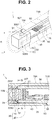
Fig. 2 is a perspective transparent view of a distal end portion of the endoscope according to the first embodiment; -
Fig. 3 is a cross-sectional view of the distal end portion of the endoscope according to the first embodiment; -
Fig. 4 is a cross-sectional view along line IV-IV of the endoscope according to the first embodiment inFig. 3 ; -
Fig. 5 is a schematic cross-sectional view for describing a bending operation of the endoscope according to the first embodiment; -
Fig. 6 is a schematic cross-sectional view for describing a bending operation of the endoscope according to the first embodiment; -
Fig. 7 is a diagram for describing a method for manufacturing an image pickup module in the endoscope according to the first embodiment; -
Fig. 8 is a diagram for describing a method for manufacturing the image pickup module in the endoscope according to the first embodiment; -
Fig. 9 is a perspective transparent view of a distal end portion of an endoscope according to a second embodiment; -
Fig. 10 is a cross-sectional view of the distal end portion of the endoscope according to the second embodiment; -
Fig. 11 is a cross-sectional view of the endoscope according to the second embodiment along line XI-XI inFig. 10 ; -
Fig. 12 is a cross-sectional view of a distal end portion of an endoscope of a third embodiment; -
Fig. 13 is a cross-sectional view of the endoscope according to the third embodiment along line XIII-XIII inFig. 12 ; -
Fig. 14 is a schematic cross-sectional view for describing a bending operation of an endoscope according to a fourth embodiment; -
Fig. 15 is a cross-sectional view of a distal end portion of the endoscope according to the fourth embodiment; -
Fig. 16 is a cross-sectional view of a distal end portion of an endoscope according to a fifth embodiment; -
Fig. 17 is a cross-sectional view of the endoscope according to the fifth embodiment along line XVII-XVII inFig. 16 ; -
Fig. 18 is a perspective view of a stacked wafer for describing a method for manufacturing the endoscope according to the fifth embodiment; -
Fig. 19A is an exploded cross-sectional view for describing another method for manufacturing the endoscope according to the fifth embodiment; -
Fig. 19B is an exploded cross-sectional view for describing another method for manufacturing the endoscope according to the fifth embodiment; -
Fig. 20 is a cross-sectional view of a distal end portion of an endoscope according to a modification of the fifth embodiment; -
Fig. 21 is a cross-sectional view of the endoscope according to the modification of the fifth embodiment along line XXI-XXI inFig. 20 ; -
Fig. 22 is a cross-sectional view of a distal end portion of an endoscope according to a sixth embodiment; -
Fig. 23 is a front view of the distal end portion of the endoscope according to the sixth embodiment; -
Fig. 24 is a cross-sectional view of a stacked wafer for describing a method for manufacturing the endoscope according to the sixth embodiment; -
Fig. 25 is a front view of a distal end portion of an endoscope according to a modification of the sixth embodiment; -
Fig. 26 is a cross-sectional view of a distal end portion of an endoscope according to a seventh embodiment; and -
Fig. 27 is a cross-sectional view of a distal end portion of an endoscope according to an eighth embodiment. - As illustrated in
Fig. 1 , anendoscope system 70 includes anendoscope 1 according to the present embodiment, aprocessor 75A and amonitor 75B. Insertion of anelongated insertion portion 73 into a body cavity of a subject allows theendoscope 1 to pick up an image of the inside of the subject and output an image pickup signal. - Note that in the following description, drawings based on the respective embodiments are schematic ones; and, e.g., a relationship between a thickness and a width of each part and ratios in thickness among, and relative angles between, the respective parts are different from actual ones, and parts that are different in dimensional relationship and/or ratio depending on the drawings may be included in the drawings. Also, illustration of some components may be omitted.
- The
endoscope 1 includes theinsertion portion 73, agrasping portion 74 disposed on the proximal end portion side of theinsertion portion 73, auniversal cord 74B provided so as to extend from thegrasping portion 74, and aconnector 74C disposed on the proximal end portion side of theuniversal cord 74B. Theinsertion portion 73 includes a rigiddistal end portion 73A in which animage pickup module 30 is disposed, abendable bending portion 73B for changing a direction of thedistal end portion 73A, thebendable bending portion 73B being provided on the proximal end side of thedistal end portion 73A, and aflexible portion 73C provided so as to extend on the proximal end side of thebending portion 73B. Theendoscope 1 is a flexible endoscope but may be a rigid endoscope if such an endoscope includes a bending portion. In other words, the flexible portion etc., are not critical components for an endoscope according to an embodiment. - A pivoting
angle knob 74A, which is an operation portion for a surgeon to operate the bendingportion 73B, is disposed at the graspingportion 74. - The
universal cord 74B is connected to aprocessor 75A via theconnector 74C. Theprocessor 75A controls theentire endoscope system 70 and performs signal processing of an image pickup signal outputted by theimage pickup module 30 and outputs the resulting image signal. Amonitor 75B displays the image signal outputted by theprocessor 75A, in the form of an endoscopic image. - As illustrated in
Figs. 2 to 4 , thedistal end portion 73A of theendoscope 1 includes acasing 40 having a cylindrical shape (having a round shape in a cross-section in a direction orthogonal to an optical axis), thecasing 40 housing theimage pickup module 30 having a substantially cuboid shape (having a rectangular shape in a cross-section in the direction orthogonal to the optical axis) inside. A sealingresin 34 such as a silicone resin or an epoxy resin is charged inside thecasing 40 including, for example, a metal such as a stainless steel, which is a rigid material. Here, an outer face of thecasing 40 may be covered by a non-illustrated resin layer. Also, a corner of thedistal end portion 73A is chambered. - It is desirable that the material of the
casing 40 have a light shielding property. Use of a light shielding material as the material of thecasing 40 can further prevent light entering from side faces of theimage pickup module 30 from affecting alight receiving section 21. - In the
image pickup module 30, anoptical module section 10 and animage pickup device 20 are stacked in a layered form. Alight receiving section 21 including, e.g., a CCD or CMOS image pickup device is formed in a light receiving surface of theimage pickup device 20 including a semiconductor. Although not illustrated, a plurality of external electrodes electrically connected to thelight receiving section 21 is disposed on a rear face of theimage pickup device 20, the rear face opposite to the light receiving surface, via, e.g., a through-wiring. The plurality of external electrodes is electrically connected to asignal cable 36 via awiring board 35. - Here, as illustrated in
Fig. 4 , thelight receiving section 21 of theimage pickup device 20 has a substantially rectangular shape. Then, the four sides of thelight receiving section 21 are parallel to the four sides of a cross-section, in a direction orthogonal to an optical axis, of theimage pickup module 30, respectively. - Then, fixed ends 50T that are opposite ends of an
operation wire 50, which is a drive member configured to bend the bendingportion 73B, are inserted in respective spaces between two opposite side faces 30S1, 30S3 of theimage pickup module 30 and an inner face of thecasing 40, over the substantial centers of the side faces 30S1, 30S3, and the respective fixed ends are fixed to the relevant side faces 30S1, 30S3 via an adhesive 51. Theoperation wire 50 is a metal wire having a round shape in a cross-section in a direction orthogonal to a longitudinal axis. - Here, for thinning the
distal end portion 73A, it is preferable that an inner diameter R40 of thecasing 40 be slightly larger than a length L30 of a diagonal line of the rectangle of the cross-section in the direction orthogonal to the optical axis of the cuboidimage pickup module 30. For example, the relationship indicated byExpression 1 below is preferable, and the relationship indicated by Expression 2 is particularly preferable.

- Furthermore, it is preferable that an outer diameter R50 of (each fixed end of) the
operation wire 50, a length D30 of the cross-section in the direction orthogonal to the optical axis of theimage pickup module 30 and the inner diameter R40 of thecasing 40 be in the relationship indicated byExpression 3 below, and particularly preferably the relationship indicated by Expression 4.

- In other words, a maximum length G of each of the spaces over the side faces of the
image pickup module 30 in the cross-section in the direction orthogonal to the optical axis, in which theoperation wire 50 is inserted, is no less than 100% and no more than 112.5% of the diameter (outer dimension) R50 of theoperation wire 50. - In other words, R50 ≤ G ≤ 1.125 × R50 (Expression 5) is preferable, and R50 ≤ G ≤ 1.05 × R50 (Expression 6) is particularly preferable.
- If the outer diameter of the
operation wire 50 is out of the aforementioned range, the fixed ends are processed so as to cause the outer diameter of each fixed end to fall within the range. For example, theoperation wire 50 is ground to decrease the outer diameter or a film of another member, for example, solder is formed on an outer face of theoperation wire 50 to increase the outer diameter. - In the
endoscope 1, theoperation wire 50 is inserted in each of the respective spaces between the side faces 30S1, 30S3 of theimage pickup module 30 and the inner face of thecasing 40. Thus, an increase in diameter R of thecasing 40 due to disposition of theoperation wire 50 is prevented. In other words, the inner diameter of thecasing 40 is selected so as to be slightly larger than a minimum diameter that enables insertion of theoperation wire 50 having a diameter of, for example, 10 µm to 100 µm into the respective spaces. A thickness of thecasing 40 is, for example, 50 µm to 100 µm. - Therefore, the diameter R40 of the
casing 40 is, for example, no more than 2 mm and thus, is small. Also, an ultra-thin endoscope including acasing 40 having a diameter R40 of less than 1 mm, which is hard to provide by following the conventional techniques, can be provided. - Note that, for example, light guides configured to guide illuminating light may be inserted through respective spaces between side faces 30S2, 30S4 of the
image pickup module 30 and the inner face of thecasing 40, in which theoperation wires 50 are not inserted. Also, the cross-sectional shape of theimage pickup module 30 may be a rectangular shape having sides having different lengths. - Next, an operation for bending, which is performed via the
angle knob 74A, will be described. As illustrated inFig. 5 , one end portion (first end portion) of theoperation wires 50 is fixed to the side face 30S1, the other end portion (second end portion) of theoperation wires 50 is fixed to the side face 30S3, and an intermediate portion of theoperation wires 50 is fixed to theangle knob 74A. - As illustrated in
Fig. 6 , upon theangle knob 74A being operated so as to pivot, for example, clockwise by a surgeon, the part of theoperation wire 50 fixed to the side face 30S1 is pulled, and on the other hand, the part of theoperation wire 50 fixed to the side face 30S3 is pushed out. Thus, the bendingportion 73B bends upward in the figure (toward the side face 30S1). Contrarily, upon theangle knob 74A being operated so as to pivot counterclockwise, the bendingportion 73B bends downward. - Next, a method for manufacturing the
image pickup module 30 will be described. As already described, in theimage pickup module 30, theoptical module section 10 and theimage pickup device 20 are stacked in a layered form. As illustrated inFigs. 7 and 8 , theoptical module section 10 is a stack in which a plurality ofoptical members 10A to 10G has been stacked in a layered form at wafer level. - In an
image pickup wafer 20W, a plurality of light receivingsections 21 etc., is disposed on, e.g., a silicon wafer, using a publicly known semiconductor manufacturing technique. Peripheral circuits each configured to perform primary processing of output signals from the relevantlight receiving section 21 or processing of drive control signals may be formed on theimage pickup wafer 20W. - An optical member stacked
wafer 10W is a stack of optical member wafers 10AW to 10GW each including a plurality of optical elements formed on the optical member wafer. For example, optical member wafers 10AW, 10CW, 10EW, 10GW are wafers each including a transparent member, and optical member wafers 10BW, 10DW, 10FE between the respective optical member wafers 10AW, 10CW, 10EW, 10GW are spacer wafers in which parts each serving as an optical path are through holes. - As illustrated in
Fig. 8 , theimage pickup module 30 is a wafer-level stack fabricated by cutting a stackedwafer 30W in which theimage pickup wafer 20W and the optical member stackedwafer 10W are stacked into individual pieces. - The respective wafers are joined via, for example, a transparent adhesive or are directly bonded. Note that the order of stacking of the wafers can be changed as necessary. For example, in order to protect the
light receiving section 21 of theimage pickup wafer 20W, anoptical member wafer 10A including a flat glass plate may be joined to theimage pickup wafer 20W, and after disposition of external electrodes on a rear face, an optical member stacked wafer including the optical member wafers 10BW to 10GW may be stacked on theoptical member wafer 10A. - Also, the stacking may be performed after each of the
image pickup wafer 20W and the optical member stackedwafer 10W being cut into individual pieces, rather than the stackedwafer 30W in which theimage pickup wafer 20W and the optical member stackedwafer 10W are stacked being cut into individual pieces. - Then, the stacked
wafer 30W is cut into individualimage pickup modules 30, which are cuboid wafer-level stacks, in such a manner that the four sides of a substantially rectangularlight receiving section 21 of eachimage pickup device 20 are parallel to the respective four sides of a rectangular cross-section orthogonal to an optical axis of the relevantimage pickup module 30. Here, after the cutting, corner portions of theimage pickup module 30, the corner portions being parallel to the optical axis, may be chamfered in such a manner that theimage pickup module 30 has a polygonal shape in a cross-section in the direction orthogonal to the optical axis. - The individual
image pickup modules 30 are housed inside respectivecylindrical casings 40. As already described, the inner diameter R40 of eachcasing 40 is slightly larger than the length L30 of a diagonal line of the rectangle of the cross-section of the cuboidimage pickup module 30. - Then, the outer diameter (outer dimension) R50 of the
operation wire 50, which is a drive member, is substantially the same as the maximum length G of the cross-section in the direction orthogonal to the optical axis of each of the spaces in which the fixed ends of theimage pickup module 30 are fixed. "Substantially the same" here means that the length G of the cross-section is slightly larger than the outer diameter R50 of theoperation wire 50, which is clear fromExpression 3 or Expression 4. Also, the maximum length G of the cross-section is a distance from a center point of a side face of theimage pickup module 30 to a point at which a straight line vertically drawn from the center point of the side face meets the inner face of thecasing 40. - Therefore, as illustrated in
Fig. 4 , upon insertion of theoperation wire 50 into the spaces between the side faces of theimage pickup module 30 and the inner face of thecasing 40, distal end portions, that is, the fixed ends of theoperation wire 50 are automatically disposed at the substantial centers of the side faces of the image pickup module 30 (image pickup device 20). - As a result of the adhesive 51 being applied to the side faces of the
image pickup module 30 in advance, the fixed ends of theoperation wire 50 are fixed to the side faces of theimage pickup module 30. Furthermore, the sealingresin 34 is charged between the side faces of theimage pickup module 30 and the inner face of thecasing 40. The sealingresin 34 may double as the adhesive 51. - At the time of manufacture of the
endoscope 1, the fixed ends of theoperation wire 50 are automatically fixed at the substantial centers of the side faces of the image pickup module 30 (image pickup device 20). Therefore, in theendoscope 1, a direction of movement of thedistal end portion 73A by an operation to bend the bendingportion 73B is orthogonal to or parallel to an endoscopic image picked up by thelight receiving section 21. In other words, an observation direction (view) moves upward/downward or leftward/rightward in an endoscopic image via an operation to bend the bendingportion 73B, and thus, theendoscope 1 has good operability. - As described above, the
endoscope 1 in which theoperation wires 50 are fixed at the centers of the side faces of the small and substantially cuboidimage pickup module 30 includes a thindistal end portion 73A and has good operability. - Note that, in the
endoscope 1, the opposite ends of asingle operation wire 50 are fixed to the two opposite side faces 30S1, 30S3 of theimage pickup module 30. On the other hand, an endoscope according to another embodiment may include a single operation wire connecting one side face 30S1 of the image pickup module and anangle knob 74A alone. Note that an endoscope including such a single operation wire alone only allows an operation for bending in one direction. However, for example, other functional members can be inserted through respective spaces between three side faces of an image pickup module and a casing. - Also, one operation wire may connect the side face 30S1 and the
angle knob 74A and another operation wire may connect the side face 30S3 and theangle knob 74A. In other words, instead of theoperation wire 50, two operation wires having a same function may be used. - Also, fixed ends of an operation wire other than the
operation wire 50 may be fixed to respective two side faces 30S2, 30S4 orthogonal to the side face 30S1 of theimage pickup module 30 and the operation wire may be connected to an angle knob other than theangle knob 74A. For example, in an endoscope configured to be bent upward/downward via anangle knob 74A, a bending portion can be bent in a direction orthogonal to a direction of bending by pivoting theangle knob 74A, by pivoting another angle knob, that is, leftward/rightward. - Note that, in this case, an observation direction moves upward/downward and leftward/rightward in a picked-up image via operations for bending by the two angle knobs.
- As described above, in an endoscope according to an embodiment, it is only necessary that a fixed end of an operation wire be fixed to at least one side face of an
image pickup module 30. - Note that another functional member may further be inserted through either of the spaces between the side faces of the
image pickup module 30 to which theoperation wire 50 is fixed and thecasing 40. - Also, an endoscope according to an embodiment may be a side viewing endoscope including an image pickup module in which an optical module includes a prism.
- Here, in the
endoscope 1, it is preferable that a strength of fixation of each of the fixed ends 50T of theoperation wire 50, which is a drive member, to theimage pickup module 30 be set to be equal to or lower than a predetermined strength. - As already described, the
endoscope 1 is ultra-thin. Thus, theendoscope 1 can be inserted into a narrow lumen into which a conventional endoscope cannot be inserted. Since a narrow lumen has a small wall thickness, an endoscope is required to have higher safety. - In the endoscope according to the present embodiment, the strength of fixation of each of the fixed ends 50T of the
operation wire 50 to theimage pickup module 30 is set to be equal to or lower than a predetermined strength. Thus, if the bendingportion 73B is largely bent by theoperation wire 50 because of, e.g., an erroneous operation and thedistal end portion 73A is strongly pressed against a wall surface of a lumen, the relevantfixed end 50T of theoperation wire 50 comes off because of a repulsion force from the wall surface, and thus, the endoscope according to the present embodiment is highly safe. - The strength of fixation of the
operation wire 50 is, for example, 1 kg, and the fixed ends 50T come off upon application of tensile stress that is equal to or higher than the strength. - If the fixed ends 50T of the
operation wire 50 come off, an operation for bending cannot be performed, but a subject is prevented from being damaged. In particular, theultra-thin endoscope 1 in which the outer diameter of the casing of the distal end portion is less than 1 mm is inserted into even a thin lumen having an inner diameter of less than 1 mm, that is, a lumen having a small wall thickness, and thus, particularly preferably has a fail-safe function. - Also, an operation wire having good conductivity may be used to provide the operation wire with a part of a function of the
signal cable 36. For example, an operation wire obtained by forming a copper plating film on an outer periphery of the stainless steel wire may be bonded and fixed to electrodes on the side faces of theimage pickup module 30 to use the operation wire as a ground potential wire or a signal wire for supplying a drive power signal. An endoscope including an operation wire having a signal wire function is thinner. - As described above, in an endoscope according to an embodiment, a
distal end portion 73A includes acasing 40 having a round shape in a cross-section orthogonal to an optical axis, and animage pickup module 30 that includes anoptical module section 10 including a plurality of optical members, and animage pickup device 20, theimage pickup module 30 having a rectangular shape in a cross-section in the direction orthogonal to the optical axis. An end portion of anoperation wire 50, which is a drive member configured to bend a bendingportion 73B, is a fixed end inserted and fixed in a space over a side face of theimage pickup module 30, and a maximum length G of a cross-section in the direction orthogonal to the optical axis of the space is no less than 100% and no more than 112.5% of an outer dimension of the fixed end of theoperation wire 50. - Next, an
endoscope 1A according to a second embodiment will be described. Theendoscope 1A is similar to theendoscope 1 and has effects that are the same as effects of theendoscope 1, and thus, components having a same function are provided with same reference numerals and description of the relevant component is omitted. - As illustrated in
Figs. 9, 10 and11 , in theendoscope 1A, acasing 41 includes a mold resin having a columnar shape (round shape in a cross-section in a direction orthogonal to an optical axis) in which an image pickup module 30 (having a rectangular shape in a cross-section in the direction orthogonal to the optical axis) is embedded. Then, fixed ends 50T of an operation wire 50 (having a round shape in a cross-section in the direction orthogonal to the optical axis), which is a drive member, are embedded in respective parts, over side faces 30S1, 30S2 of theimage pickup module 30, of thecasing 41. - In other words, in the
endoscope 1A, also, theoperation wire 50 is inserted and fixed in spaces between the side faces of theimage pickup module 30 having a rectangular shape in a cross-section and an outer face of thecasing 41 having a round shape in a cross-section. - For the
casing 41, theimage pickup module 30 is inserted into amold 40A having a shape corresponding to thecasing 41. Next, theoperation wire 50 is inserted into respective spaces between the relevant side faces of theimage pickup module 30 and themold 40A. Then, a mold resin is injected into the spaces and subjected to cure treatment, and thecasing 41 is thus fabricated. The mold resin is, e.g., an epoxy resin or a fluorine resin, which is a hard resin having a Rockwell hardness (JIS K7202-2, measurement temperature: 23°C) of no less than HR100 on the R scale. - As with the inner diameter of the
casing 40 of theendoscope 1, in an inner diameter of themold 40A, a length of each of the spaces between an inner face of themold 40A and theoperation wire 50 is set. In other words, it is preferable that the inner diameter of themold 40A meet, e.g., conditions obtained by replacement of the inner diameter R40 of thecasing 40 inExpression 1 to Expression 6 with the inner diameter of themold 40A. - If the above conditions are met, upon the
operation wire 50 being disposed in the respective spaces between parts of themold 40A on the relevant side faces of theimage pickup module 30 and the side faces, theoperation wire 50 is automatically disposed at substantial centers of the side faces. - The
endoscope 1A is thinner than theendoscope 1 including a tubular body for holding, e.g., theimage pickup module 30 in thedistal end portion 73A. Also, theimage pickup module 30 having a stacked structure is housed inside the mold resin including a member that is harder than the bending portion. Even if bending stress is applied to thedistal end portion 73A as a result of an operation of theoperation wire 50, thecasing 41 including a hard mold resin does not deform. Thus, theimage pickup module 30 having a stacked structure is protected from effects caused by operation of theoperation wire 50. - Note that, in order to firmly fix the
operation wire 50, the front side of thecasing 41 may include a hard resin and the rear side of thecasing 41 may include another soft resin. - Also, a
light receiving section 21 can be prevented from being affected by light entering from side faces of theimage pickup module 30 by covering theimage pickup module 30 using a mold resin in which a light-shielding member such as carbon power is mixed. In this case, the covering of theimage pickup module 30 extending to a rear face of theimage pickup device 20 is particularly preferable because light penetrating silicon such as infrared light can be blocked. - Next, an
endoscope 1B according to a third embodiment will be described. Theendoscope 1B is similar to theendoscope 1 and has effects that are the same as the effects of theendoscope 1, and thus, components having a same function are provided with same reference numerals and description of the relevant component is omitted. - As illustrated in
Figs. 12 and 13 , in theendoscope 1B, fixed ends 50T that are opposite ends of anoperation wire 50, which is a drive member, are fixed to an inner face of acylindrical casing 42 that houses animage pickup module 30 inside, respectively, via an adhesive 31. Positions at which the fixed ends 50T are fixed are located in respective areas over substantial centers of side faces 30S1, 30S3 of theimage pickup module 30. - In other words, in the
endoscope 1B, also, theoperation wire 50 is inserted and fixed in the respective spaces between the side faces of the rectangularimage pickup module 30 and the inner face of thecasing 42. - The
image pickup module 30 may be inserted after fixation of the fixed ends 50T of theoperation wire 50 at two opposite positions in the inner face of thecasing 42, or theoperation wire 50 may be fixed to thecasing 42 in which theimage pickup module 30 is inserted. - As with the inner diameter of the
casing 40 in theendoscope 1, it is preferable that an inner diameter of thecasing 42 meet, e.g., the conditions ofExpression 1 to Expression 6. - If the
casing 42 meets the above conditions, theoperation wire 50 is automatically disposed at substantial centers of the side faces of theimage pickup module 30. - In the side faces of the
image pickup module 30, e.g., glass, which is largely different in thermal expansion coefficient from theoperation wire 50 including a metal and is subject to breakage is exposed. Thus, in the case of theendoscope 1, fixation of theoperation wire 50 to theimage pickup module 30 may be not easy. On the other hand, in the case of theendoscope 1B, theoperation wire 50 is fixed to the inner face of thecasing 42 including a metal, and thus, is easy to manufacture and has high reliability. Note that the fixation of theoperation wire 50 to the inner face of the casing is not limited to fixation using an adhesive but may be fixation using solder bonding. - Note that the fixed ends of the
operation wire 50 may be fixed to both the side faces of theimage pickup module 30 and the inner face of thecasing 42. - As described above, an endoscope in which an
operation wire 50 is inserted and fixed in a space between a side face of a cuboidimage pickup module 30, which is a wafer-level stack, and a casing having a round shape in a cross-section can easily be thinned, and have good operability because an observation direction is moved upward/downward (leftward/rightward) in an endoscopic image by an operation for bending. - Next, an
endoscope 1C according to a fourth embodiment will be described. Theendoscope 1C is similar to theendoscopes endoscope 1 and the like") and has effects that are the same as the effects of theendoscope 1 and the like, and thus components having a same function are provided with same reference numerals and description of the relevant component is omitted. - As illustrated in
Fig. 14 , in theendoscope 1C, drive members for bending a bendingportion 73B arebimetallic strips 52 on which aheater 53, which is a heating section, is disposed. - In each
bimetallic strip 52, afirst metal 52A and asecond metal 52B that are different from each other in thermal expansion coefficient are stacked. Then, if thebimetallic strip 52 is heated by therelevant heater 53, thebimetallic strip 52 bends according to temperature variation resulting from the heating. Note that, although not illustrated, a conductive wire configured to supply power is connected to theheater 53, and is inserted through aninsertion portion 73, and power supplied to theheater 53 is increased/decreased by pivoting anangle knob 74A of a graspingportion 74. Also, instead of theheater 53, thebimetallic strip 52 itself may be used as a heating element. - Respective end portions (fixed ends) 52T of two
bimetallic strips 52 are fixed to respective side faces 30S1, 30S3 of animage pickup module 30. - Note that the
fixed end 52T may be fixed to an area over the side face 30S1 of theimage pickup module 30. In other words, as with theendoscope 1A, thefixed end 52T may be embedded in acasing 41 including a mold resin, or as with theendoscope 1B, thefixed end 52T may be fixed to an inner face of a cylindrical casing. - As illustrated in
Fig. 15 , in theendoscope 1C, acolumnar casing 41 includes a mold resin. Fixation portions of distal ends ofrespective drive members 54A to 54D are joined to areas over side faces 30S1 to 30S4 of theimage pickup module 30 via an adhesive (not illustrated). Furthermore, fourlight guides 81 to 84 configured to guide illuminating light and an illumination optical system (not illustrated) are embedded in areas over the side faces 30S1 to 30S4 of theimage pickup module 30. - Here, a direction of bending of each
bimetallic strip 52 is different between a time when thebimetallic strip 52 is heated and a time when thebimetallic strip 52 is cooled. Therefore, a cooling section such as a Peltier device may be provided instead of theheater 53, which is a heating section. Also, disposing a heating section and a cooling section on onebimetallic strip 52 enables bending in two directions via thebimetallic strip 52. - The
endoscope 1C includes no operation wire inserted through aflexible portion 73C, and thus has a simple structure and is thinner than theendoscope 1 etc. - Here, each of the drive members may be a bimorph piezoelectric body in which two piezoelectric bodies that are different from each other in a rate of deformation according to an applied voltage are stacked. In this case, instead of the
heater 53, an electrode configured to apply a voltage is disposed on the bimorph piezoelectric body. - Since the bimorph piezoelectric bodies are higher in deformation speed than the
bimetallic strips 52, and thus, have high responsiveness to an operation of an operation portion compared to thebimetallic strips 52. - As described above, the drive member is not limited to the
operation wire 50 and may be, e.g., a bimetallic strip or a bimorph piezoelectric body if the bimetallic strip or the bimorph piezoelectric body can bend the bending portion. - Next, an
endoscope 1D according to a fifth embodiment will be described. Theendoscope 1D is similar to theendoscope 1 and the like and has effects that are the same as the effects of theendoscope 1 and the like, and thus, components having a same function are provided with same reference numerals and description of the relevant component is omitted. - As illustrated in
Figs. 16 and 17 , theendoscope 1D includes aninsertion portion 73 that includes andistal end portion 73A and a bendingportion 73B configured to change a direction of thedistal end portion 73A, the bendingportion 73B being provided so as to extend from thedistal end portion 73A, and thedistal end portion 73A includes acasing 40 having a round shape in a cross-section in a direction orthogonal to an optical axis, and animage pickup module 30D that includes anoptical module section 10 including a plurality ofoptical members 10A to 10F, and animage pickup section 20D, theimage pickup module 30D having a rectangular shape in a cross-section in the direction, and theimage pickup section 20D includes animage pickup device 20 and asemiconductor stack 60 in which a plurality ofsemiconductor devices image pickup module 30D is completely housed inside thecasing 40. - In the
semiconductor stack 60, the plurality ofsemiconductor devices 61 to 63 is stacked via respective sealing resin layers 66. Thesemiconductor devices 61 to 63 in which a planer device 64 is formed are connected via respective through-wirings 65. - Entirety of the
image pickup module 30D is completely housed inside thecasing 40 having a round shape in a cross-section in the direction orthogonal to the optical axis. Asignal cable 36 bonded to thestack 60 is provided to extend in a rear portion of thecasing 40. - The
semiconductor devices 61 to 63 in which a planer device 64 is formed each process an image signal generated by theimage pickup device 20 and output the resulting signal to thesignal cable 36. Each of the planer devices 64 is, e.g., a buffer, a capacitor, an inductor, a resistor, a denoising circuit or an analog-digital conversion circuit, and is one formed by what is called a semiconductor manufacturing process. - As illustrated in
Fig. 18 , theimage pickup module 30D is a wafer-level stack fabricated by cutting a stacked wafer 30DW. In the stacked wafer 30DW, an optical member stackedwafer 10W, animage pickup wafer 20W and a semiconductor stackedwafer 60W are stacked. In the optical member stackedwafer 10W, optical member wafers 10AW, 10CW, 10EW, 10GW are stacked. In the semiconductor stackedwafer 60W,semiconductor wafers - The
semiconductor wafers semiconductor devices semiconductor devices respective semiconductor wafers - The
image pickup module 30D in which thesemiconductor stack 60 is bonded to a rear face of theimage pickup device 20 is short. Furthermore, respective throughvias 54 are formed in thesemiconductor devices 61 to 63, and a size of projection on a surface orthogonal to the optical axis direction of theimage stack 60 is a size that falls within a projection surface in the optical axis direction of theimage pickup device 20. - The
endoscope 1D includes the short and small-diameterimage pickup module 30D and thedistal end portion 73A is short and has a small diameter, and thus theendoscope 1D is less invasive. - Furthermore, the
endoscope 1D is highly reliable because entirety of theimage pickup module 30D is completely housed in thecasing 40 that does not deform. - Note that, in the
endoscope 1D, theimage pickup module 30D is a single wafer-level stack. On the other hand, as illustrated inFig. 19A , a semiconductor stackedwafer 60W may be cut after disposition of animage pickup module 30, which is a wafer-level stack of anoptical module section 10 and animage pickup device 20, on the semiconductor stackedwafer 60W. Also, as illustrated inFig. 19B , anoptical module section 10 may be joined to a stacked wafer of an image pickup wafer 20AW including a cover glass wafer 10AW and a semiconductor stackedwafer 60W. - Next, an endoscope IE according to a modification of the fifth embodiment will be described. The
endoscope 1E relates to theendoscopes endoscope 1E is similar to theendoscopes endoscopes - As illustrated in
Figs. 20 and 21 , in the endoscope IE, in addition to the configuration of theendoscope 1D, end portions ofoperation wires 50A, 50B are inserted and fixed in spaces over side faces of theimage pickup module 30D. - A
casing 40 has a cylindrical shape, and animage pickup module 30D has a rectangular shape in a cross-section. Thus, a maximum length of a cross-section of the space between a side face of theimage pickup module 30D and an inner face of thecasing 40 varies depending on the orthogonal side face of theimage pickup module 30D. - In other words, where G1 is a maximum length of the space over a long-side side face, a maximum length G2 of the space over a short-side side face is smaller than G1.
- It is preferable that the lengths G1, G2 of the spaces in which the
operation wires 50A, 50B are inserted be no less than 100% and no more than 112.5% of respective outer diameters (outer dimensions) of theoperation wires 50A, 50B. Therefore, the outer diameter R50B of the operation wire 50B is smaller than the outer diameter R50A of theoperation wire 50A. - In the
endoscope 1E, also, it should be understood that: the number of operation wires is not limited to four; and the endoscope IE has the effects of both theendoscope 1 and theendoscope 1D even if the number of operation wires is two or one. - Next, an
endoscope 1F according to a sixth embodiment will be described. Theendoscope 1F is similar to theendoscope 1D and the like, and has effects that are the same as the effects of theendoscopes endoscope 1D and the like, and thus, components having a same function are provided with same reference numerals and description of the relevant component is omitted. - As illustrated in
Figs. 22 and 23 , in theendoscope 1F, a stepped portion C10 is provided in an outer peripheral portion of a frontmostoptical member 10G in anoptical module section 10S, a sealingresin 34 covering an outer peripheral face of theoptical module section 10S is charged in the stepped portion C10. - As illustrated in
Fig. 24 , two-step dicing (stepwise dicing) is performed in a step of cutting a stacked wafer 30DW in a process of manufacturing the endoscope IE. For example, first, trenches T10 are formed along cutting lines CL in a most upper optical member wafer 10GW by afirst dicing blade 88. Subsequently, the stacked wafer 30DW is cut into individualoptical module sections 10S by asecond dicing blade 89 having a width that is smaller than a width of thefirst dicing blade 88. - The
optical module section 10S of theendoscope 1F is prevented from projecting from a front face of thecasing 40, by the sealingresin 34 charged in the stepped portion C10. - Note that, in the
endoscope 1F, the stepped portion C10 is provided around the entire outer peripheral portion of the frontmostoptical member 10G. However, like theendoscope 1G illustrated inFig. 25 , even if a stepped portion C10G is provided only in some parts, for example, corner portions of the outer peripheral portion of theoptical member 10G, theendoscope 1G has effects that are the same as the effects of theendoscope 1F. - Next, an
endoscope 1H according to a seventh embodiment and an endoscope 1I according to an eighth embodiment will be described. Theendoscope 1H is similar to theendoscopes endoscope 1 and the like. Also, the endoscope 1I is similar to theendoscopes endoscope 1 and the like. Thus, components having a same function are provided with same reference numerals and description of the relevant component is omitted. - As illustrated in
Fig. 26 , in theendoscope 1H, entirety of animage pickup module 30F is completely housed inside acylindrical casing 40. Then, a maximum length G of a cross-section of each of spaces over side faces of theimage pickup module 30F, in which end portions of anoperation wire 50, which is a drive member, are fixed, is no less than 100% and no more than 112.5% of an outer dimension of the fixed end. Furthermore, a stepped portion C10 is provided in an outer peripheral portion of a frontmostoptical member 10G in anoptical module section 10S, and a sealingresin 34 covering an outer peripheral face of theoptical module section 10S is charged in the stepped portion C10. - As illustrated in
Fig. 27 , in the endoscope 1I, entirety of animage pickup module 30F is completely housed inside acasing 41 including a mold resin. Then, a maximum length G of a cross-section of each of spaces over side faces of animage pickup module 30F, in which end portions of anoperation wire 50, which is a drive member, are fixed, is no less than 100% and no more than 112.5% of an outer dimension of the fixed end. Furthermore, a stepped portion C10 is provided in an outer peripheral portion of a frontmostoptical member 10G in anoptical module section 10S, and the mold resin of thecasing 41 is charged in the stepped portion C10. - It should be understood that an endoscope according to an embodiment of the present invention is not limited to a medical endoscope and may be an industrial endoscope.
- The present invention is not limited to the above-described embodiments and modifications and the like, and various changes, combinations and applications are possible without departing from the spirit of the invention.
- The present application is filed claiming the priority from the international application (Application No.
PCT/JP2015/080181) filed on October 27, 2015 -
- 1, 1A to 1I ... endoscope
- 10, 10S ... optical module section
- 10A ... optical member wafer
- 10W ... optical member stacked wafer
- 20 ... image pickup device
- 20W ... image pickup wafer
- 20D ... image pickup section
- 21 ... light receiving section
- 30 ... image pickup module
- 30W ... stacked wafer
- 31 ... adhesive
- 34 ... sealing resin
- 35 ... wiring board
- 36 ... signal cable
- 40, 41, 42 ... casing
- 40A ... mold
- 50 ... operation wire
- 50T ... fixed end
- 51 ... adhesive
- 54 ... through-via
- 60 ... semiconductor stack
- 60W ... semiconductor stacked wafer
- 61 to 63 ... semiconductor device
- 61W to 63W ... semiconductor wafer
- 64 ... planer device
- 65 ... through-wiring
- 66 ... sealing resin layer
- 70 ... endoscope system
- 73 ... insertion portion
- 73A ... distal end portion
- 73B ... bending portion
- 88, 89 ... dicing blade
Claims (12)
- An endoscope comprising an insertion portion that includes a distal end portion, and a bending portion configured to change a direction of the distal end portion, the bending portion being provided so as to extend from the distal end portion, wherein:the distal end portion includes a casing having a round shape in a cross-section, and an image pickup module that includes an optical module section including a plurality of optical members and an image pickup section, the image pickup module having a rectangular shape in a cross-section;the image pickup section includes an image pickup device, and a semiconductor stack in which a plurality of semiconductor devices is stacked; andentirety of the image pickup module is completely housed inside the casing.
- The endoscope according to claim 1, wherein:an end portion of a drive member configured to bend the bending portion is a fixed end inserted and fixed in a space over a side face of the image pickup module; anda maximum length of a cross-section of the space is no less than 100% and no more than 112.5% of an outer dimension of the fixed end.
- The endoscope according to claim 2, wherein:the drive member is an operation wire having a round shape in a cross-section; anda diameter R50 of the operation wire, a length D30 of the image pickup module and a diameter R40 of the casing meet the following expression:

- The endoscope according to claim 3, wherein the fixed end is fixed to the side face of the image pickup module.
- The endoscope according to claim 3 or 4, wherein the fixed end is fixed to an inner face of the casing having a cylindrical shape.
- The endoscope according to claim 3, wherein:the casing includes a columnar mold resin in which the image pickup module is embedded; andthe fixed end is embedded in the mold resin.
- The endoscope according to any one of claims 1 to 6, wherein the image pickup module is a wafer-level stack.
- The endoscope according to any one of claims 1 to 7, wherein an outer diameter of the casing is less than 1 mm.
- An endoscope comprising an insertion portion that includes a distal end portion, and a bending portion configured to change a direction of the distal end portion, the bending portion being provided so as to extend from the distal end portion, wherein:the distal end portion includes a casing having a round shape in a cross-section, and an image pickup module that includes an optical module section including a plurality of optical members and an image pickup device, the image pickup module having a rectangular shape in a cross-section;an end portion of a drive member configured to bend the bending portion is a fixed end inserted and fixed in a space over a side face of the image pickup module; anda maximum length of a cross-section of the space is no less than 100% and no more than 112.5% of an outer dimension of the fixed end.
- The endoscope according to any one of claims 1 to 9, wherein an outer peripheral portion of a frontmost optical member in the optical module section includes a stepped portion, and a sealing resin covering an outer peripheral face of the optical module section is charged in the stepped portion.
- The endoscope according to claim 1, wherein a material of the casing is a light-shielding member.
- The endoscope according to claim 6, wherein the mold resin is a resin in which a light-shielding member is mixed.
Applications Claiming Priority (2)
| Application Number | Priority Date | Filing Date | Title |
|---|---|---|---|
| PCT/JP2015/080181 WO2017072847A1 (en) | 2015-10-27 | 2015-10-27 | Endoscope |
| PCT/JP2016/081041 WO2017073440A1 (en) | 2015-10-27 | 2016-10-20 | Endoscope |
Publications (2)
| Publication Number | Publication Date |
|---|---|
| EP3369363A1 true EP3369363A1 (en) | 2018-09-05 |
| EP3369363A4 EP3369363A4 (en) | 2019-11-06 |
Family
ID=58630132
Family Applications (1)
| Application Number | Title | Priority Date | Filing Date |
|---|---|---|---|
| EP16859670.8A Withdrawn EP3369363A4 (en) | 2015-10-27 | 2016-10-20 | Endoscope |
Country Status (5)
| Country | Link |
|---|---|
| US (1) | US11109749B2 (en) |
| EP (1) | EP3369363A4 (en) |
| JP (1) | JPWO2017073440A1 (en) |
| CN (1) | CN108348144A (en) |
| WO (2) | WO2017072847A1 (en) |
Cited By (1)
| Publication number | Priority date | Publication date | Assignee | Title |
|---|---|---|---|---|
| US11099374B2 (en) | 2017-06-29 | 2021-08-24 | Olympus Corporation | Endoscope |
Families Citing this family (20)
| Publication number | Priority date | Publication date | Assignee | Title |
|---|---|---|---|---|
| WO2018098465A1 (en) | 2016-11-28 | 2018-05-31 | Inventio, Inc. | Endoscope with separable, disposable shaft |
| WO2018211652A1 (en) * | 2017-05-18 | 2018-11-22 | オリンパス株式会社 | Imaging device and endoscope |
| WO2019138442A1 (en) * | 2018-01-09 | 2019-07-18 | オリンパス株式会社 | Imaging device, endoscope, and method for manufacturing imaging device |
| WO2019138440A1 (en) | 2018-01-09 | 2019-07-18 | オリンパス株式会社 | Imaging device, endoscope, and manufacturing method for imaging device |
| WO2019138463A1 (en) * | 2018-01-10 | 2019-07-18 | オリンパス株式会社 | Method for manufacturing optical unit, optical unit, and endoscope |
| WO2019138462A1 (en) * | 2018-01-10 | 2019-07-18 | オリンパス株式会社 | Imaging device, endoscope, and method for manufacturing imaging device |
| JP2019160830A (en) * | 2018-03-07 | 2019-09-19 | ソニーセミコンダクタソリューションズ株式会社 | Imaging element and manufacturing method thereof |
| WO2020003398A1 (en) * | 2018-06-27 | 2020-01-02 | オリンパス株式会社 | Endoscope and endoscopic imaging device |
| WO2020090049A1 (en) * | 2018-10-31 | 2020-05-07 | 株式会社住田光学ガラス | Endoscope |
| US11690497B2 (en) * | 2018-11-27 | 2023-07-04 | Fujikura Ltd. | Lens unit |
| CN113169192A (en) * | 2018-12-19 | 2021-07-23 | 奥林巴斯株式会社 | Imaging device and method for manufacturing imaging device |
| WO2020152782A1 (en) * | 2019-01-22 | 2020-07-30 | オリンパス株式会社 | Method for manufacturing endoscope imaging device, endoscope imaging device, and endoscope |
| WO2020208750A1 (en) * | 2019-04-10 | 2020-10-15 | オリンパス株式会社 | Method for manufacturing imaging device, imaging device, and endoscope |
| USD1018844S1 (en) | 2020-01-09 | 2024-03-19 | Adaptivendo Llc | Endoscope handle |
| WO2021152658A1 (en) * | 2020-01-27 | 2021-08-05 | オリンパス株式会社 | Imaging device and endoscope |
| WO2021161452A1 (en) * | 2020-02-13 | 2021-08-19 | オリンパス株式会社 | Endoscope and imaging module |
| WO2021176704A1 (en) * | 2020-03-06 | 2021-09-10 | オリンパス株式会社 | Optical unit, optical-unit manufacturing method, and endoscope |
| JP7272507B2 (en) | 2020-04-10 | 2023-05-12 | コニカミノルタ株式会社 | Gas detection device, gas detection method, and gas detection program |
| DE102020111455A1 (en) * | 2020-04-27 | 2021-10-28 | Schölly Fiberoptic GmbH | Flexible endoscope based on an investment material |
| DE102020111458A1 (en) | 2020-04-27 | 2021-10-28 | Schölly Fiberoptic GmbH | Flexible endoscope with a skeletal structure |
Family Cites Families (28)
| Publication number | Priority date | Publication date | Assignee | Title |
|---|---|---|---|---|
| US4772093A (en) * | 1985-12-12 | 1988-09-20 | Microvasive, Inc. | Fiber-optic image-carrying device |
| US4779613A (en) * | 1986-03-13 | 1988-10-25 | Olympus Optical Co., Ltd. | Endoscope with means for preventing an observing optical system from being fogged |
| JPS6365840A (en) * | 1986-04-04 | 1988-03-24 | オリンパス光学工業株式会社 | Endoscope |
| US5438975A (en) * | 1993-03-24 | 1995-08-08 | Machida Endoscope Co., Ltd. | Distal tip of endoscope having spirally coiled control wires |
| JP3394604B2 (en) * | 1994-08-02 | 2003-04-07 | オリンパス光学工業株式会社 | Ultrasonic probe with bending mechanism |
| JPH08280603A (en) * | 1995-04-17 | 1996-10-29 | Olympus Optical Co Ltd | Cover type endoscope |
| US6132390A (en) * | 1996-02-28 | 2000-10-17 | Eupalamus Llc | Handle for manipulation of a stylet used for deflecting a tip of a lead or catheter |
| JP2001128930A (en) * | 1999-11-01 | 2001-05-15 | Olympus Optical Co Ltd | Endoscope |
| CN100440544C (en) * | 2002-09-17 | 2008-12-03 | 安特约恩股份有限公司 | Camera device, method of manufacturing a camera device, wafer scale package |
| JP4398184B2 (en) * | 2003-06-24 | 2010-01-13 | オリンパス株式会社 | Endoscope |
| US8435173B2 (en) * | 2003-10-06 | 2013-05-07 | Olympus Corporation | Endoscope |
| JP2005312555A (en) * | 2004-04-27 | 2005-11-10 | Olympus Corp | Endoscope |
| JP4722912B2 (en) * | 2005-03-08 | 2011-07-13 | オリンパスメディカルシステムズ株式会社 | Endoscope, endoscope manufacturing method |
| US20070052050A1 (en) * | 2005-09-07 | 2007-03-08 | Bart Dierickx | Backside thinned image sensor with integrated lens stack |
| US7749799B2 (en) * | 2005-11-15 | 2010-07-06 | California Institute Of Technology | Back-illuminated imager and method for making electrical and optical connections to same |
| US20090171150A1 (en) * | 2007-12-27 | 2009-07-02 | Olympus Corporation | Observation unit detachable type endoscope and endoscope main body |
| JP5325416B2 (en) * | 2007-12-27 | 2013-10-23 | オリンパスメディカルシステムズ株式会社 | Endoscope body and endoscope |
| JP2009240634A (en) * | 2008-03-31 | 2009-10-22 | Olympus Corp | Endoscope apparatus |
| JP5424825B2 (en) * | 2009-11-12 | 2014-02-26 | オリンパス株式会社 | Stacked mounting structure |
| JP2012018993A (en) | 2010-07-06 | 2012-01-26 | Toshiba Corp | Camera module and method of manufacturing the same |
| US20120029289A1 (en) * | 2010-07-29 | 2012-02-02 | Cannuflow, Inc. | Optical Cap for Use With Arthroscopic System |
| JP5721981B2 (en) * | 2010-09-10 | 2015-05-20 | オリンパス株式会社 | Imaging unit and endoscope including imaging unit |
| JP2012075658A (en) * | 2010-09-30 | 2012-04-19 | Fujifilm Corp | Endoscope apparatus |
| JP6270339B2 (en) * | 2013-05-22 | 2018-01-31 | オリンパス株式会社 | Imaging apparatus, manufacturing method of imaging apparatus, and endoscope system |
| US9872606B2 (en) * | 2013-12-27 | 2018-01-23 | University Of Washington Through Its Center For Commercialization | Adaptive control of a fiber scanner with piezoelectric sensing |
| WO2015164912A1 (en) * | 2014-05-02 | 2015-11-05 | Intellimedical Technologies Pty Ltd | Elongate steerable devices for insertion into a subject's body |
| CN108289618A (en) * | 2015-11-30 | 2018-07-17 | 新日本无线株式会社 | Photoelectric sensor |
| DE112016006906T5 (en) * | 2016-05-24 | 2019-03-07 | Olympus Corporation | Image recording unit for an endoscope and endoscope |
-
2015
- 2015-10-27 WO PCT/JP2015/080181 patent/WO2017072847A1/en active Application Filing
-
2016
- 2016-10-20 WO PCT/JP2016/081041 patent/WO2017073440A1/en active Application Filing
- 2016-10-20 EP EP16859670.8A patent/EP3369363A4/en not_active Withdrawn
- 2016-10-20 CN CN201680062696.8A patent/CN108348144A/en active Pending
- 2016-10-20 JP JP2017547756A patent/JPWO2017073440A1/en active Pending
-
2018
- 2018-04-20 US US15/958,063 patent/US11109749B2/en active Active
Cited By (1)
| Publication number | Priority date | Publication date | Assignee | Title |
|---|---|---|---|---|
| US11099374B2 (en) | 2017-06-29 | 2021-08-24 | Olympus Corporation | Endoscope |
Also Published As
| Publication number | Publication date |
|---|---|
| EP3369363A4 (en) | 2019-11-06 |
| US20180303325A1 (en) | 2018-10-25 |
| CN108348144A (en) | 2018-07-31 |
| WO2017073440A1 (en) | 2017-05-04 |
| US11109749B2 (en) | 2021-09-07 |
| JPWO2017073440A1 (en) | 2018-08-09 |
| WO2017072847A1 (en) | 2017-05-04 |
Similar Documents
| Publication | Publication Date | Title |
|---|---|---|
| EP3369363A1 (en) | Endoscope | |
| US9462933B2 (en) | Image pickup unit for endoscope | |
| JP4916595B2 (en) | Imaging unit | |
| US20170035279A1 (en) | Image pickup unit and electronic endoscope including the image pickup unit | |
| US20120293641A1 (en) | Image pickup unit for endoscope | |
| US20180070799A1 (en) | Imaging device, endoscope system, and method of manufacturing imaging device | |
| CN106886088B (en) | Endoscope with a detachable handle | |
| WO2016111075A1 (en) | Imaging unit, imaging module and endoscopic system | |
| JP5399305B2 (en) | Imaging apparatus and endoscope | |
| US20180045948A1 (en) | Stereo image pickup unit | |
| US20150279764A1 (en) | Semiconductor device connection structure, ultrasonic module, and ultrasonic endoscope system having ultrasonic module | |
| WO2019176601A1 (en) | Imaging unit and oblique endoscope | |
| US9629524B2 (en) | Image pickup unit for endoscope having first and second leads with differing distances to image pickup device | |
| US10542874B2 (en) | Imaging device and endoscope device | |
| US10456013B2 (en) | Cable connection structure, imaging apparatus, and endoscope | |
| US20180296076A1 (en) | Imageing device and endoscope | |
| US20180310813A1 (en) | Imageing unit and endoscope | |
| JP2016214660A (en) | Medical camera head and medical camera device | |
| JP6209288B2 (en) | Miniaturization of imaging device | |
| US20170059850A1 (en) | Endoscope | |
| CN115079397A (en) | Camera module | |
| JP2022142220A (en) | Imaging module | |
| WO2011092904A1 (en) | Structure for tip of endoscope | |
| JP2022179301A (en) | Endoscope imaging apparatus and endoscope |
Legal Events
| Date | Code | Title | Description |
|---|---|---|---|
| PUAI | Public reference made under article 153(3) epc to a published international application that has entered the european phase |
Free format text: ORIGINAL CODE: 0009012 |
|
| 17P | Request for examination filed |
Effective date: 20180525 |
|
| AK | Designated contracting states |
Kind code of ref document: A1 Designated state(s): AL AT BE BG CH CY CZ DE DK EE ES FI FR GB GR HR HU IE IS IT LI LT LU LV MC MK MT NL NO PL PT RO RS SE SI SK SM TR |
|
| AX | Request for extension of the european patent |
Extension state: BA ME |
|
| DAV | Request for validation of the european patent (deleted) | ||
| DAX | Request for extension of the european patent (deleted) | ||
| A4 | Supplementary search report drawn up and despatched |
Effective date: 20191008 |
|
| RIC1 | Information provided on ipc code assigned before grant |
Ipc: G02B 23/24 20060101ALI20191001BHEP Ipc: A61B 1/04 20060101AFI20191001BHEP |
|
| STAA | Information on the status of an ep patent application or granted ep patent |
Free format text: STATUS: THE APPLICATION IS DEEMED TO BE WITHDRAWN |
|
| 18D | Application deemed to be withdrawn |
Effective date: 20200603 |