EP3369148B1 - Process for quantum random number generation in a multimode laser cavity - Google Patents
Process for quantum random number generation in a multimode laser cavity Download PDFInfo
- Publication number
- EP3369148B1 EP3369148B1 EP16781692.5A EP16781692A EP3369148B1 EP 3369148 B1 EP3369148 B1 EP 3369148B1 EP 16781692 A EP16781692 A EP 16781692A EP 3369148 B1 EP3369148 B1 EP 3369148B1
- Authority
- EP
- European Patent Office
- Prior art keywords
- cavity
- laser
- round trip
- random
- modes
- Prior art date
- Legal status (The legal status is an assumption and is not a legal conclusion. Google has not performed a legal analysis and makes no representation as to the accuracy of the status listed.)
- Active
Links
Images
Classifications
-
- G—PHYSICS
- G06—COMPUTING OR CALCULATING; COUNTING
- G06F—ELECTRIC DIGITAL DATA PROCESSING
- G06F7/00—Methods or arrangements for processing data by operating upon the order or content of the data handled
- G06F7/58—Random or pseudo-random number generators
- G06F7/588—Random number generators, i.e. based on natural stochastic processes
-
- G—PHYSICS
- G06—COMPUTING OR CALCULATING; COUNTING
- G06N—COMPUTING ARRANGEMENTS BASED ON SPECIFIC COMPUTATIONAL MODELS
- G06N10/00—Quantum computing, i.e. information processing based on quantum-mechanical phenomena
- G06N10/40—Physical realisations or architectures of quantum processors or components for manipulating qubits, e.g. qubit coupling or qubit control
-
- H—ELECTRICITY
- H01—ELECTRIC ELEMENTS
- H01S—DEVICES USING THE PROCESS OF LIGHT AMPLIFICATION BY STIMULATED EMISSION OF RADIATION [LASER] TO AMPLIFY OR GENERATE LIGHT; DEVICES USING STIMULATED EMISSION OF ELECTROMAGNETIC RADIATION IN WAVE RANGES OTHER THAN OPTICAL
- H01S3/00—Lasers, i.e. devices using stimulated emission of electromagnetic radiation in the infrared, visible or ultraviolet wave range
- H01S3/10—Controlling the intensity, frequency, phase, polarisation or direction of the emitted radiation, e.g. switching, gating, modulating or demodulating
- H01S3/11—Mode locking; Q-switching; Other giant-pulse techniques, e.g. cavity dumping
- H01S3/1106—Mode locking
-
- H—ELECTRICITY
- H01—ELECTRIC ELEMENTS
- H01S—DEVICES USING THE PROCESS OF LIGHT AMPLIFICATION BY STIMULATED EMISSION OF RADIATION [LASER] TO AMPLIFY OR GENERATE LIGHT; DEVICES USING STIMULATED EMISSION OF ELECTROMAGNETIC RADIATION IN WAVE RANGES OTHER THAN OPTICAL
- H01S5/00—Semiconductor lasers
- H01S5/06—Arrangements for controlling the laser output parameters, e.g. by operating on the active medium
- H01S5/062—Arrangements for controlling the laser output parameters, e.g. by operating on the active medium by varying the potential of the electrodes
- H01S5/06226—Modulation at ultra-high frequencies
- H01S5/0623—Modulation at ultra-high frequencies using the beating between two closely spaced optical frequencies, i.e. heterodyne mixing
-
- H—ELECTRICITY
- H01—ELECTRIC ELEMENTS
- H01S—DEVICES USING THE PROCESS OF LIGHT AMPLIFICATION BY STIMULATED EMISSION OF RADIATION [LASER] TO AMPLIFY OR GENERATE LIGHT; DEVICES USING STIMULATED EMISSION OF ELECTROMAGNETIC RADIATION IN WAVE RANGES OTHER THAN OPTICAL
- H01S5/00—Semiconductor lasers
- H01S5/06—Arrangements for controlling the laser output parameters, e.g. by operating on the active medium
- H01S5/065—Mode locking; Mode suppression; Mode selection ; Self pulsating
-
- H—ELECTRICITY
- H01—ELECTRIC ELEMENTS
- H01S—DEVICES USING THE PROCESS OF LIGHT AMPLIFICATION BY STIMULATED EMISSION OF RADIATION [LASER] TO AMPLIFY OR GENERATE LIGHT; DEVICES USING STIMULATED EMISSION OF ELECTROMAGNETIC RADIATION IN WAVE RANGES OTHER THAN OPTICAL
- H01S5/00—Semiconductor lasers
- H01S5/06—Arrangements for controlling the laser output parameters, e.g. by operating on the active medium
- H01S5/065—Mode locking; Mode suppression; Mode selection ; Self pulsating
- H01S5/0657—Mode locking, i.e. generation of pulses at a frequency corresponding to a roundtrip in the cavity
-
- H—ELECTRICITY
- H01—ELECTRIC ELEMENTS
- H01S—DEVICES USING THE PROCESS OF LIGHT AMPLIFICATION BY STIMULATED EMISSION OF RADIATION [LASER] TO AMPLIFY OR GENERATE LIGHT; DEVICES USING STIMULATED EMISSION OF ELECTROMAGNETIC RADIATION IN WAVE RANGES OTHER THAN OPTICAL
- H01S5/00—Semiconductor lasers
- H01S5/30—Structure or shape of the active region; Materials used for the active region
- H01S5/3013—AIIIBV compounds
-
- G—PHYSICS
- G06—COMPUTING OR CALCULATING; COUNTING
- G06F—ELECTRIC DIGITAL DATA PROCESSING
- G06F2207/00—Indexing scheme relating to methods or arrangements for processing data by operating upon the order or content of the data handled
- G06F2207/58—Indexing scheme relating to groups G06F7/58 - G06F7/588
-
- H—ELECTRICITY
- H01—ELECTRIC ELEMENTS
- H01S—DEVICES USING THE PROCESS OF LIGHT AMPLIFICATION BY STIMULATED EMISSION OF RADIATION [LASER] TO AMPLIFY OR GENERATE LIGHT; DEVICES USING STIMULATED EMISSION OF ELECTROMAGNETIC RADIATION IN WAVE RANGES OTHER THAN OPTICAL
- H01S5/00—Semiconductor lasers
- H01S5/06—Arrangements for controlling the laser output parameters, e.g. by operating on the active medium
- H01S5/062—Arrangements for controlling the laser output parameters, e.g. by operating on the active medium by varying the potential of the electrodes
- H01S5/06209—Arrangements for controlling the laser output parameters, e.g. by operating on the active medium by varying the potential of the electrodes in single-section lasers
- H01S5/06213—Amplitude modulation
-
- H—ELECTRICITY
- H01—ELECTRIC ELEMENTS
- H01S—DEVICES USING THE PROCESS OF LIGHT AMPLIFICATION BY STIMULATED EMISSION OF RADIATION [LASER] TO AMPLIFY OR GENERATE LIGHT; DEVICES USING STIMULATED EMISSION OF ELECTROMAGNETIC RADIATION IN WAVE RANGES OTHER THAN OPTICAL
- H01S5/00—Semiconductor lasers
- H01S5/06—Arrangements for controlling the laser output parameters, e.g. by operating on the active medium
- H01S5/065—Mode locking; Mode suppression; Mode selection ; Self pulsating
- H01S5/0651—Mode control
- H01S5/0652—Coherence lowering or collapse, e.g. multimode emission by additional input or modulation
-
- H—ELECTRICITY
- H04—ELECTRIC COMMUNICATION TECHNIQUE
- H04L—TRANSMISSION OF DIGITAL INFORMATION, e.g. TELEGRAPHIC COMMUNICATION
- H04L9/00—Cryptographic mechanisms or cryptographic arrangements for secret or secure communications; Network security protocols
- H04L9/08—Key distribution or management, e.g. generation, sharing or updating, of cryptographic keys or passwords
- H04L9/0861—Generation of secret information including derivation or calculation of cryptographic keys or passwords
- H04L9/0869—Generation of secret information including derivation or calculation of cryptographic keys or passwords involving random numbers or seeds
Definitions
- the present invention relates to random number generators (RNGs), in particular to generators based on the intrinsic randomness of quantum observables in multimode laser cavities with variable gain or loss.
- RNGs random number generators
- Random numbers form sequences of numbers or symbols that lack any pattern, appear random.
- a random number generator is a computational or physical device designed to generate random numbers. RNGs can be classified in pseudo-RNGs (PRNGs), computational algorithms, and true-RNGs (TRNGs). TRNGs are physical devices and can be subdivided into classical RNGs (CRNGs) based on classical deterministic laws, and quantum RNGs (QRNGs) based on quantum effects.
- PRNGs pseudo-RNGs
- TRNGs true-RNGs
- TRNGs are physical devices and can be subdivided into classical RNGs (CRNGs) based on classical deterministic laws, and quantum RNGs (QRNGs) based on quantum effects.
- the patent application "ultrafast quantum random number generator and system thereof" by Pruneri et al [5] discloses a QRNG based on measuring quantum phase diffusion in a pulsed single-mode semiconductor laser. By modulating the laser from below to above threshold, optical pulses with nearly identical intensities and completely randomized phases are generated. Then, by using an external interferometer, the random phases are translated into random amplitudes, which can be digitised with a PIN detector. Instead of one laser source and an interferometer, two laser sources can be used together with a combiner. The technique allows for ultrafast operation regimes, and recent publications have shown bitrates up to 40-80 Gbps [7,8].
- the invention is based on the transformation of the random phases of the modes of a multimode laser into random intensity patterns that can be detected with a fast photodiode.
- the invention comprises the steps of utilizing a multimode laser whose net gain per round trip is modulated continuously from positive to negative values and viceversa by means of an electrical pulse driver, maintaining net gain per round trip positive for a longer period than the round trip time of the cavity, maintaining net gain per round trip negative for a longer period than the round trip time of the cavity and detecting the resulting beating pattern between the longitudinal modes of the laser cavity utilizing a fast photodiode (PIN).
- PIN fast photodiode
- a multimode laser for implementing the invention, for example a Fabry Perot cavity semiconductor laser whose multimode response is achieved through proper wavelength selective reflectors or a fiber ring laser comprising fiber Bragg gratings for mode selection and a semiconductor optical amplifier as gain medium.
- Any laser cavity which has at least two modes is in principle suitable as long as the net gain, i.e. the difference between gain and loss in the cavity, of at least one of the at least two modes can be properly modulated, in particular to achieve sufficiently negative net gain values and, correspondingly, large phase diffusion.
- the laser gain, the loss of the cavity or, alternatively, both the laser gain and cavity loss can be modulated.
- the laser experiences two stable working regimes: (i) above threshold, in which the different longitudinal modes of the multimode laser will create a random intensity pattern characterized by the frequency spacing and the relative phases between the modes, and (ii) below threshold, in which the laser cavity field is forced to operate in a spontaneous emission regime, resetting and randomising in this way the relative phases between the modes for the next modulation period.
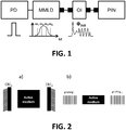
- Fig 1 shows a first set up for putting into practice the invention, in which a two-mode laser is obtained via selective filtering within the cavity of a multimode laser diode (MMLD).
- the MMLD is modulated by means of an electrical pulse driver (PD). Since only two modes are selected in the example, the beating pattern when detected with the photodiode (PIN) shows cosine dependence with a frequency given by the mode spacing (frequency difference between modes m 2 and m 3 in the figure) and initial phase ⁇ init given by the phase difference between the modes in that particular period.
- An optical isolator (OI) can be added to avoid optical back reflections into the laser cavity.
- the resulting intensity pattern shows cosine dependence, due to the dual-mode emission, with a random initial phase.
- sampling subsequent pulses produces digitization of random amplitudes, since each pulse generated by modulating the effective laser cavity gain is built on the random initial phase of the two modes.
- the larger the number of modes involved in the beating the more complex the resulting intensity pattern and the larger the number of random samples that can be extracted within each net gain modulation period.
- modulating the net gain of the laser cavity is essential for the system to provide quantum random samples (numbers). If the net gain were kept constant above threshold, mode beating would still exist but correlations would be present between the pulses leaving the cavity. If the net gain were modulated with a frequency correlated to the round trip of the cavity, this mode beating could become what is known as mode-locking producing a train of periodic pulses.
- a similar structure for an integrated version of the scheme could be made as follows: placing the active material inside or on top of a photonic integrated circuit (PIC), and using the cleaved facets of the chip itself as mirrors.
- the spectral filtering can be achieved either by placing gratings on both sides of the active material, or by using a ring-like structure.
- Fig. 2 an active material such as InP or InGaAsPis placed in a Fabry Perot cavity with highly reflective end mirrors.
- the spectral reflectivity of the mirrors can be engineered so that the cavity itself acts as a filter allowing only a few modes to oscillate.
- the two reflective mirrors can filter two desired modes (CRC 1,2 ).
- CRC 1,2 desired modes
- the separation between the mirrors and the refractive index of the material in between determines the mode spacing.
- the cavity is designed so that the mode spacing is smaller than the detection bandwidth, the inter-mode beating of the laser can be resolved with a fast photodiode (PIN).
- Fig. 2b the active material is deposited on top of a photonic chip and using the reflection produced by the cleaved facets of a chip the cavity is created.
- the spectral filtering is obtained by means of gratings.
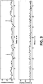
- Fig. 3 shows the autocorrelation function for two operating regimes: (upper picture) the laser never reaches the spontaneous emission regime, and (lower picture) the laser successfully reaches the spontaneous emission regime.
- the correlation function reveals that patterns between subsequent pulses are similar (shown as peaks in the figure). Instead, in the bottom picture, no correlation is observable due to complete randomization of the phase between subsequent pulses.
Landscapes
- Physics & Mathematics (AREA)
- General Physics & Mathematics (AREA)
- Electromagnetism (AREA)
- Optics & Photonics (AREA)
- Engineering & Computer Science (AREA)
- Condensed Matter Physics & Semiconductors (AREA)
- Theoretical Computer Science (AREA)
- General Engineering & Computer Science (AREA)
- Pure & Applied Mathematics (AREA)
- Mathematical Optimization (AREA)
- Mathematical Analysis (AREA)
- Computational Mathematics (AREA)
- Plasma & Fusion (AREA)
- Data Mining & Analysis (AREA)
- Artificial Intelligence (AREA)
- Evolutionary Computation (AREA)
- Computing Systems (AREA)
- Mathematical Physics (AREA)
- Software Systems (AREA)
- Semiconductor Lasers (AREA)
- Optical Modulation, Optical Deflection, Nonlinear Optics, Optical Demodulation, Optical Logic Elements (AREA)
Description
- The present invention relates to random number generators (RNGs), in particular to generators based on the intrinsic randomness of quantum observables in multimode laser cavities with variable gain or loss.
- Random numbers form sequences of numbers or symbols that lack any pattern, appear random. A random number generator (RNG) is a computational or physical device designed to generate random numbers. RNGs can be classified in pseudo-RNGs (PRNGs), computational algorithms, and true-RNGs (TRNGs). TRNGs are physical devices and can be subdivided into classical RNGs (CRNGs) based on classical deterministic laws, and quantum RNGs (QRNGs) based on quantum effects.
- Current commercial RNG devices are based on the spatial distribution of single photons [1], chaotic dynamics in semiconductor lasers [2], CMOS metastability [3], single photon detection in arrays of single photon detectors [4], or phase diffusion in semiconductor lasers [5,6], among many other schemes.
- The patent application "ultrafast quantum random number generator and system thereof" by Pruneri et al [5] discloses a QRNG based on measuring quantum phase diffusion in a pulsed single-mode semiconductor laser. By modulating the laser from below to above threshold, optical pulses with nearly identical intensities and completely randomized phases are generated. Then, by using an external interferometer, the random phases are translated into random amplitudes, which can be digitised with a PIN detector. Instead of one laser source and an interferometer, two laser sources can be used together with a combiner. The technique allows for ultrafast operation regimes, and recent publications have shown bitrates up to 40-80 Gbps [7,8]. However, the need of an external interferometric element or two lasers which are spectrally matched in emission and coupling optics complicates the layout as it increases the number of elements, the overall dimension of the QRNG device, and, in some cases the performance of the QRNG is affected by the stability of the components. For example, in the case of the two lasers their emission wavelength spectra have to be narrow (single mode), matched and maintained over time and this is not always easy to achieve due to intrinsic instability and environmental changes.
- There is thus a need of a smaller form factor RNG source, with reduced dimensions (footprint) which maintains the ultrafast and quantum mechanical entropy properties.
- It is the aim of the invention to provide a process for quantum random number generation and a system therefore that overcomes the limitations of the prior art. The invention is based on the transformation of the random phases of the modes of a multimode laser into random intensity patterns that can be detected with a fast photodiode. For this purpose, the invention comprises the steps of utilizing a multimode laser whose net gain per round trip is modulated continuously from positive to negative values and viceversa by means of an electrical pulse driver, maintaining net gain per round trip positive for a longer period than the round trip time of the cavity, maintaining net gain per round trip negative for a longer period than the round trip time of the cavity and detecting the resulting beating pattern between the longitudinal modes of the laser cavity utilizing a fast photodiode (PIN).
- There are many different schemes of a multimode laser for implementing the invention, for example a Fabry Perot cavity semiconductor laser whose multimode response is achieved through proper wavelength selective reflectors or a fiber ring laser comprising fiber Bragg gratings for mode selection and a semiconductor optical amplifier as gain medium. Any laser cavity which has at least two modes is in principle suitable as long as the net gain, i.e. the difference between gain and loss in the cavity, of at least one of the at least two modes can be properly modulated, in particular to achieve sufficiently negative net gain values and, correspondingly, large phase diffusion.
- For modulating the net gain, the laser gain, the loss of the cavity or, alternatively, both the laser gain and cavity loss can be modulated. In each modulation cycle, the laser experiences two stable working regimes: (i) above threshold, in which the different longitudinal modes of the multimode laser will create a random intensity pattern characterized by the frequency spacing and the relative phases between the modes, and (ii) below threshold, in which the laser cavity field is forced to operate in a spontaneous emission regime, resetting and randomising in this way the relative phases between the modes for the next modulation period. Not succeeding in bringing the laser below threshold and keeping it in such a condition for a time sufficiently long compared to the round trip time so that the stimulated emission photons leave the cavity before generating a new stimulated emission pulse would introduce correlations between the patterns of subsequent pulses. Thanks to the invention, it is possible to provide quantum numbers without any external or interferometric element, with a very compact (small footprint) system, especially when integrated photonic circuits are used to build it.
- To complete the description for a better understanding of the invention a set of drawings is provided. Said drawings illustrate preferred embodiments of the invention, which should not be interpreted as restricting the scope of the invention, but just as an example of how the invention can be embodied.
-
Fig. 1 shows a possible set up for putting the invention into practice. -
Fig. 2 shows another set up. -
Fig. 3 shows the autocorrelation function for two operating regimes of a multi-mode laser. -
Fig 1 shows a first set up for putting into practice the invention, in which a two-mode laser is obtained via selective filtering within the cavity of a multimode laser diode (MMLD). The MMLD is modulated by means of an electrical pulse driver (PD). Since only two modes are selected in the example, the beating pattern when detected with the photodiode (PIN) shows cosine dependence with a frequency given by the mode spacing (frequency difference between modes m2 and m3 in the figure) and initial phase Φinit given by the phase difference between the modes in that particular period. An optical isolator (OI) can be added to avoid optical back reflections into the laser cavity. - The resulting intensity pattern shows cosine dependence, due to the dual-mode emission, with a random initial phase. Hence, sampling subsequent pulses produces digitization of random amplitudes, since each pulse generated by modulating the effective laser cavity gain is built on the random initial phase of the two modes. The larger the number of modes involved in the beating, the more complex the resulting intensity pattern and the larger the number of random samples that can be extracted within each net gain modulation period.
- Note that modulating the net gain of the laser cavity is essential for the system to provide quantum random samples (numbers). If the net gain were kept constant above threshold, mode beating would still exist but correlations would be present between the pulses leaving the cavity. If the net gain were modulated with a frequency correlated to the round trip of the cavity, this mode beating could become what is known as mode-locking producing a train of periodic pulses.
- A similar structure for an integrated version of the scheme could be made as follows: placing the active material inside or on top of a photonic integrated circuit (PIC), and using the cleaved facets of the chip itself as mirrors. The spectral filtering can be achieved either by placing gratings on both sides of the active material, or by using a ring-like structure.
- In
Fig. 2 an active material such as InP or InGaAsPis placed in a Fabry Perot cavity with highly reflective end mirrors. The spectral reflectivity of the mirrors can be engineered so that the cavity itself acts as a filter allowing only a few modes to oscillate. InFig. 2a the two reflective mirrors can filter two desired modes (CRC1,2). By electrically pumping the active medium, lasing can take place and a broad multimode optical spectrum is generated. The separation between the mirrors and the refractive index of the material in between determines the mode spacing. Finally, if the cavity is designed so that the mode spacing is smaller than the detection bandwidth, the inter-mode beating of the laser can be resolved with a fast photodiode (PIN). - In
Fig. 2b the active material is deposited on top of a photonic chip and using the reflection produced by the cleaved facets of a chip the cavity is created. The spectral filtering is obtained by means of gratings. -
Fig. 3 shows the autocorrelation function for two operating regimes: (upper picture) the laser never reaches the spontaneous emission regime, and (lower picture) the laser successfully reaches the spontaneous emission regime. In the top picture, since the laser never reaches the spontaneous emission region, the correlation function reveals that patterns between subsequent pulses are similar (shown as peaks in the figure). Instead, in the bottom picture, no correlation is observable due to complete randomization of the phase between subsequent pulses. - In this text, the term "comprises" and its derivations (such as "comprising", etc.) should not be understood in an excluding sense, that is, these terms should not be interpreted as excluding the possibility that what is described and defined may include further elements, steps, etc.
- On the other hand, the invention is obviously not limited to the specific embodiment(s) described herein, but also encompasses any variations that may be considered by any person skilled in the art (for example, as regards the choice components, configuration, etc.), within the general scope of the invention as defined in the claims.
-
- [1] G. Ribordy et al, "Method and apparatus for generating true random numbers by way of a quantum optics process",
US 7519641 B2 (2009 ). - [2] A. Uchida et al, "Fast physical random bit generation with chaotic semiconductor lasers", Nat. Photonics, vol. 2, 12, 728-732 (2008)
- [3] H.C. Herbert et al, "Digital random number generator",
US20100332574A1 (2010 ) - [4] S. Tisa et al, "High-Speed Quantum Random Number Generation Using CMOS Photon Counting Detectors", IEEE Journal of Selected Topics in Quantum Electronics, (21) 3, 23-29 (2015)
- [5] V. Pruneri et al, "Ultrafast quantum random number generation process and system therefor",
US2013/0036145 A1 - [6] F. Xu et al, "An ultrafast quantum random number generator based on quantum phase fluctuations", Opt. )
- [7] Z.L. Yuan et al, "Robust random number generation using steady-state emission of gain-switched laser diodes", Appl. Phys. Lett. 104, 261112 (2014)
- [8] C. Abellan et al, "Ultra-fast quantum randomness generation by accelerated phase diffusion in a pulsed laser diode", Opt. Express 22, 1645 (2014)
Claims (4)
- A process for producing random numbers by means of a quantum random number generator, the process comprising the steps of:a) operating a multimode laser diode in high modulation bandwidth and depth by means of an electrical pulse driver that modulates the net gain continuously from positive to negative values and vice-versa;b) maintaining the net gain per round trip positive over a period longer than the round trip time of the cavity;c) maintaining the time net gain per round trip negative over a period longer than the round trip time of the cavity;d) detecting the resulting random beating pattern between the multiple modes in a) by means of a fast photodiode;e) obtaining random numbers by sampling subsequent pulses so as to produce a digitization of random amplitudes.
- A process according to claim 1 further comprising selecting a number of frequencies within the laser cavity so as to reduce the number of modes involved in the beating process.
- A process according to claims 1-2 in which the laser is operated at a non-resonant frequency, such that a locking mechanism between the longitudinal modes of the cavity is prevented.
- A process according to any of the previous claims further comprising a step of optically isolating the signals so as to avoid reflected optical power into the laser cavity.
Applications Claiming Priority (2)
| Application Number | Priority Date | Filing Date | Title |
|---|---|---|---|
| US14/923,495 US9710230B2 (en) | 2015-10-27 | 2015-10-27 | Process for quantum random number generation in a multimode laser cavity |
| PCT/EP2016/073099 WO2017071901A1 (en) | 2015-10-27 | 2016-09-28 | Process for quantum random number generation in a multimode laser cavity |
Publications (2)
| Publication Number | Publication Date |
|---|---|
| EP3369148A1 EP3369148A1 (en) | 2018-09-05 |
| EP3369148B1 true EP3369148B1 (en) | 2019-08-14 |
Family
ID=57136827
Family Applications (1)
| Application Number | Title | Priority Date | Filing Date |
|---|---|---|---|
| EP16781692.5A Active EP3369148B1 (en) | 2015-10-27 | 2016-09-28 | Process for quantum random number generation in a multimode laser cavity |
Country Status (6)
| Country | Link |
|---|---|
| US (1) | US9710230B2 (en) |
| EP (1) | EP3369148B1 (en) |
| JP (1) | JP6945539B2 (en) |
| KR (1) | KR102626031B1 (en) |
| CN (1) | CN108352677B (en) |
| WO (1) | WO2017071901A1 (en) |
Families Citing this family (13)
| Publication number | Priority date | Publication date | Assignee | Title |
|---|---|---|---|---|
| US10019235B2 (en) | 2011-09-30 | 2018-07-10 | Los Alamos National Security, Llc | Quantum random number generators |
| WO2019086730A1 (en) | 2017-11-06 | 2019-05-09 | Fundació Institut De Ciències Fotòniques | Method for physical random number generation using a vertical cavity surface emitting laser |
| RU2662641C1 (en) * | 2018-02-22 | 2018-07-26 | Андрей Николаевич Климов | Quantum random number generator |
| CN108446099B (en) * | 2018-05-02 | 2024-05-14 | 如般量子科技有限公司 | Source-independent high-dimensional time-coded quantum random number generator |
| CN111522530B (en) * | 2019-02-03 | 2023-07-18 | 华为技术有限公司 | Quantum random number generator and key generation system |
| EP3703283A1 (en) * | 2019-02-27 | 2020-09-02 | Fundació Institut de Ciències Fotòniques | Generation of optical pulses with controlled distributions of quadrature values |
| GB2582311B (en) * | 2019-03-18 | 2021-10-20 | Toshiba Kk | A quantum random number generator |
| CN110426863B (en) * | 2019-07-01 | 2021-04-23 | 中国科学技术大学 | A quantum random switch |
| ES2861512B2 (en) | 2020-04-03 | 2022-12-30 | Univ Vigo | Quantum Random Number Generator |
| CN112217477A (en) * | 2020-09-03 | 2021-01-12 | 广东工业大学 | Device and method for generating millimeter wave noise by quantum phase fluctuation |
| EP4037115A1 (en) * | 2021-02-01 | 2022-08-03 | Quside Technologies S.L. | Random number generator comprising a vertical cavity surface emitting laser |
| DE102024205605A1 (en) * | 2024-06-18 | 2025-12-18 | Fraunhofer-Gesellschaft zur Förderung der angewandten Forschung eingetragener Verein | Random number generator and method for generating random information |
| CN119960729B (en) * | 2025-01-09 | 2026-03-24 | 哈尔滨工业大学(深圳)(哈尔滨工业大学深圳科技创新研究院) | A method and system for generating true random numbers based on quantum dot lasers |
Family Cites Families (14)
| Publication number | Priority date | Publication date | Assignee | Title |
|---|---|---|---|---|
| US6487151B1 (en) * | 1994-12-20 | 2002-11-26 | Matsushita Electric Industrial Co. Ltd. | Optical information recording and reproducing system with overwrite capability and recording medium for use therewith |
| US6873797B2 (en) * | 2001-01-30 | 2005-03-29 | The Regents Of The University Of California | Optical layer multicasting |
| US7519641B2 (en) | 2003-08-27 | 2009-04-14 | Id Quantique S.A. | Method and apparatus for generating true random numbers by way of a quantum optics process |
| WO2006038660A1 (en) * | 2004-10-06 | 2006-04-13 | Matsushita Electric Industrial Co., Ltd. | Data communication system |
| WO2007083417A1 (en) * | 2006-01-20 | 2007-07-26 | Niigata University | Physical random number generation method and physical random number generator |
| JP5196093B2 (en) * | 2006-04-20 | 2013-05-15 | 日本電気株式会社 | Optical communication apparatus and quantum cryptography key distribution system using the same |
| JP4950924B2 (en) * | 2008-03-19 | 2012-06-13 | 日本電信電話株式会社 | Chaos laser oscillator, ultra-high speed physical random number generator and method using the same, program, and recording medium |
| US8489660B2 (en) | 2009-06-26 | 2013-07-16 | Intel Corporation | Digital random number generator using partially entropic data |
| GB0915000D0 (en) * | 2009-08-27 | 2009-09-30 | Univ Bruxelles | Quantum random number generation |
| ES2378024B1 (en) * | 2011-08-04 | 2013-01-29 | Fundació Institut De Ciències Fotòniques | ULTRARFAST QUANTUM GENERATION PROCEDURE OF RANDOM NUMBERS AND SYSTEM TO CARRY OUT THE PROCEDURE. |
| CN102681817B (en) * | 2012-06-05 | 2015-03-04 | 太原理工大学 | All-optical true random number generator with Tbps-level code rate |
| CN103793198B (en) * | 2014-01-24 | 2017-01-04 | 上海交通大学 | Based on quantum random number generator and the method for amplifying vacuum state |
| CN103942030B (en) * | 2014-03-25 | 2017-02-08 | 电子科技大学 | True random number generation method and device |
| CN104516713B (en) * | 2014-12-29 | 2017-11-14 | 太原理工大学 | A kind of full light true random number generation device |
-
2015
- 2015-10-27 US US14/923,495 patent/US9710230B2/en active Active
-
2016
- 2016-09-28 WO PCT/EP2016/073099 patent/WO2017071901A1/en not_active Ceased
- 2016-09-28 CN CN201680062838.0A patent/CN108352677B/en active Active
- 2016-09-28 KR KR1020187014879A patent/KR102626031B1/en active Active
- 2016-09-28 EP EP16781692.5A patent/EP3369148B1/en active Active
- 2016-09-28 JP JP2018541494A patent/JP6945539B2/en active Active
Non-Patent Citations (1)
| Title |
|---|
| None * |
Also Published As
| Publication number | Publication date |
|---|---|
| JP6945539B2 (en) | 2021-10-06 |
| US20170115960A1 (en) | 2017-04-27 |
| KR20180073663A (en) | 2018-07-02 |
| CN108352677A (en) | 2018-07-31 |
| WO2017071901A1 (en) | 2017-05-04 |
| CN108352677B (en) | 2020-07-07 |
| KR102626031B1 (en) | 2024-01-18 |
| US9710230B2 (en) | 2017-07-18 |
| EP3369148A1 (en) | 2018-09-05 |
| JP2019500707A (en) | 2019-01-10 |
Similar Documents
| Publication | Publication Date | Title |
|---|---|---|
| US9710230B2 (en) | Process for quantum random number generation in a multimode laser cavity | |
| US9218160B2 (en) | Ultrafast quantum random number generation process and system therefore | |
| Sciamanna et al. | Physics and applications of laser diode chaos | |
| Soriano et al. | Complex photonics: Dynamics and applications of delay-coupled semiconductors lasers | |
| Delfyett et al. | Advanced ultrafast technologies based on optical frequency combs | |
| Lee et al. | Dynamical characterisation of laser diode subject to double optical feedback for chaotic optical communications | |
| US12080993B2 (en) | Method for physical random number generation using a vertical cavity surface emitting laser | |
| Zhong et al. | Tunable broadband chaotic signal synthesis from a WRC-FPLD subject to filtered feedback | |
| Alkhazragi et al. | Semiconductor emitters in entropy sources for quantum random number generation | |
| Chen et al. | Optical chaos generation and applications | |
| Shakhovoy et al. | Wavelength-and time-division multiplexing via pump current variation of a pulsed semiconductor laser—A method of synchronization for quantum key distribution | |
| Deng et al. | Generation and Intelligent synchronization of photonic millimeter-wave chaos | |
| EP3731081A1 (en) | Compact digitization system for generating random numbers | |
| CN105490160A (en) | All-optical laser device for locking repetition frequency and method for applying device | |
| RU122208U1 (en) | SUBPIC-SECOND HOLMIC FIBER LASER PUMPED SEMICONDUCTOR DISK LASER | |
| Raffaelli et al. | A soi integrated quantum random number generator based on phase fluctuations from a laser diode | |
| Caspani et al. | Integrated source of multiplexed photon pairs | |
| Ohtsubo et al. | Chaotic optical communication | |
| Abellan et al. | Integrated quantum entropy sources | |
| Li et al. | Tri-comb and quad-comb generation from a multidimensional-multiplexed fiber laser | |
| Doumbia | Optical injection dynamics and polarization properties of semiconductor lasers frequency combs | |
| Roztocki et al. | Pulsed quantum frequency combs from an actively mode-locked intra-cavity generation scheme | |
| JP2025100307A (en) | Optical device, optical transmitter and optical quantum random number generator | |
| HK40029680A (en) | Method for physical random number generation using a vertical cavity surface emitting laser | |
| Pasquazi et al. | Mode-locked laser based on an integrated nonlinear microring resonator generating a dual comb. |
Legal Events
| Date | Code | Title | Description |
|---|---|---|---|
| STAA | Information on the status of an ep patent application or granted ep patent |
Free format text: STATUS: THE INTERNATIONAL PUBLICATION HAS BEEN MADE |
|
| PUAI | Public reference made under article 153(3) epc to a published international application that has entered the european phase |
Free format text: ORIGINAL CODE: 0009012 |
|
| STAA | Information on the status of an ep patent application or granted ep patent |
Free format text: STATUS: REQUEST FOR EXAMINATION WAS MADE |
|
| 17P | Request for examination filed |
Effective date: 20180518 |
|
| AK | Designated contracting states |
Kind code of ref document: A1 Designated state(s): AL AT BE BG CH CY CZ DE DK EE ES FI FR GB GR HR HU IE IS IT LI LT LU LV MC MK MT NL NO PL PT RO RS SE SI SK SM TR |
|
| AX | Request for extension of the european patent |
Extension state: BA ME |
|
| DAV | Request for validation of the european patent (deleted) | ||
| DAX | Request for extension of the european patent (deleted) | ||
| GRAP | Despatch of communication of intention to grant a patent |
Free format text: ORIGINAL CODE: EPIDOSNIGR1 |
|
| STAA | Information on the status of an ep patent application or granted ep patent |
Free format text: STATUS: GRANT OF PATENT IS INTENDED |
|
| INTG | Intention to grant announced |
Effective date: 20190225 |
|
| GRAS | Grant fee paid |
Free format text: ORIGINAL CODE: EPIDOSNIGR3 |
|
| GRAA | (expected) grant |
Free format text: ORIGINAL CODE: 0009210 |
|
| STAA | Information on the status of an ep patent application or granted ep patent |
Free format text: STATUS: THE PATENT HAS BEEN GRANTED |
|
| AK | Designated contracting states |
Kind code of ref document: B1 Designated state(s): AL AT BE BG CH CY CZ DE DK EE ES FI FR GB GR HR HU IE IS IT LI LT LU LV MC MK MT NL NO PL PT RO RS SE SI SK SM TR |
|
| REG | Reference to a national code |
Ref country code: GB Ref legal event code: FG4D |
|
| REG | Reference to a national code |
Ref country code: CH Ref legal event code: EP Ref country code: AT Ref legal event code: REF Ref document number: 1168138 Country of ref document: AT Kind code of ref document: T Effective date: 20190815 |
|
| REG | Reference to a national code |
Ref country code: IE Ref legal event code: FG4D |
|
| REG | Reference to a national code |
Ref country code: DE Ref legal event code: R096 Ref document number: 602016018708 Country of ref document: DE |
|
| REG | Reference to a national code |
Ref country code: NL Ref legal event code: MP Effective date: 20190814 |
|
| REG | Reference to a national code |
Ref country code: LT Ref legal event code: MG4D |
|
| PG25 | Lapsed in a contracting state [announced via postgrant information from national office to epo] |
Ref country code: SE Free format text: LAPSE BECAUSE OF FAILURE TO SUBMIT A TRANSLATION OF THE DESCRIPTION OR TO PAY THE FEE WITHIN THE PRESCRIBED TIME-LIMIT Effective date: 20190814 Ref country code: NL Free format text: LAPSE BECAUSE OF FAILURE TO SUBMIT A TRANSLATION OF THE DESCRIPTION OR TO PAY THE FEE WITHIN THE PRESCRIBED TIME-LIMIT Effective date: 20190814 Ref country code: BG Free format text: LAPSE BECAUSE OF FAILURE TO SUBMIT A TRANSLATION OF THE DESCRIPTION OR TO PAY THE FEE WITHIN THE PRESCRIBED TIME-LIMIT Effective date: 20191114 Ref country code: LT Free format text: LAPSE BECAUSE OF FAILURE TO SUBMIT A TRANSLATION OF THE DESCRIPTION OR TO PAY THE FEE WITHIN THE PRESCRIBED TIME-LIMIT Effective date: 20190814 Ref country code: HR Free format text: LAPSE BECAUSE OF FAILURE TO SUBMIT A TRANSLATION OF THE DESCRIPTION OR TO PAY THE FEE WITHIN THE PRESCRIBED TIME-LIMIT Effective date: 20190814 Ref country code: PT Free format text: LAPSE BECAUSE OF FAILURE TO SUBMIT A TRANSLATION OF THE DESCRIPTION OR TO PAY THE FEE WITHIN THE PRESCRIBED TIME-LIMIT Effective date: 20191216 Ref country code: FI Free format text: LAPSE BECAUSE OF FAILURE TO SUBMIT A TRANSLATION OF THE DESCRIPTION OR TO PAY THE FEE WITHIN THE PRESCRIBED TIME-LIMIT Effective date: 20190814 Ref country code: NO Free format text: LAPSE BECAUSE OF FAILURE TO SUBMIT A TRANSLATION OF THE DESCRIPTION OR TO PAY THE FEE WITHIN THE PRESCRIBED TIME-LIMIT Effective date: 20191114 |
|
| REG | Reference to a national code |
Ref country code: AT Ref legal event code: MK05 Ref document number: 1168138 Country of ref document: AT Kind code of ref document: T Effective date: 20190814 |
|
| PG25 | Lapsed in a contracting state [announced via postgrant information from national office to epo] |
Ref country code: GR Free format text: LAPSE BECAUSE OF FAILURE TO SUBMIT A TRANSLATION OF THE DESCRIPTION OR TO PAY THE FEE WITHIN THE PRESCRIBED TIME-LIMIT Effective date: 20191115 Ref country code: LV Free format text: LAPSE BECAUSE OF FAILURE TO SUBMIT A TRANSLATION OF THE DESCRIPTION OR TO PAY THE FEE WITHIN THE PRESCRIBED TIME-LIMIT Effective date: 20190814 Ref country code: IS Free format text: LAPSE BECAUSE OF FAILURE TO SUBMIT A TRANSLATION OF THE DESCRIPTION OR TO PAY THE FEE WITHIN THE PRESCRIBED TIME-LIMIT Effective date: 20191214 Ref country code: ES Free format text: LAPSE BECAUSE OF FAILURE TO SUBMIT A TRANSLATION OF THE DESCRIPTION OR TO PAY THE FEE WITHIN THE PRESCRIBED TIME-LIMIT Effective date: 20190814 Ref country code: RS Free format text: LAPSE BECAUSE OF FAILURE TO SUBMIT A TRANSLATION OF THE DESCRIPTION OR TO PAY THE FEE WITHIN THE PRESCRIBED TIME-LIMIT Effective date: 20190814 Ref country code: AL Free format text: LAPSE BECAUSE OF FAILURE TO SUBMIT A TRANSLATION OF THE DESCRIPTION OR TO PAY THE FEE WITHIN THE PRESCRIBED TIME-LIMIT Effective date: 20190814 |
|
| PG25 | Lapsed in a contracting state [announced via postgrant information from national office to epo] |
Ref country code: TR Free format text: LAPSE BECAUSE OF FAILURE TO SUBMIT A TRANSLATION OF THE DESCRIPTION OR TO PAY THE FEE WITHIN THE PRESCRIBED TIME-LIMIT Effective date: 20190814 |
|
| PG25 | Lapsed in a contracting state [announced via postgrant information from national office to epo] |
Ref country code: AT Free format text: LAPSE BECAUSE OF FAILURE TO SUBMIT A TRANSLATION OF THE DESCRIPTION OR TO PAY THE FEE WITHIN THE PRESCRIBED TIME-LIMIT Effective date: 20190814 Ref country code: RO Free format text: LAPSE BECAUSE OF FAILURE TO SUBMIT A TRANSLATION OF THE DESCRIPTION OR TO PAY THE FEE WITHIN THE PRESCRIBED TIME-LIMIT Effective date: 20190814 Ref country code: EE Free format text: LAPSE BECAUSE OF FAILURE TO SUBMIT A TRANSLATION OF THE DESCRIPTION OR TO PAY THE FEE WITHIN THE PRESCRIBED TIME-LIMIT Effective date: 20190814 Ref country code: PL Free format text: LAPSE BECAUSE OF FAILURE TO SUBMIT A TRANSLATION OF THE DESCRIPTION OR TO PAY THE FEE WITHIN THE PRESCRIBED TIME-LIMIT Effective date: 20190814 Ref country code: IT Free format text: LAPSE BECAUSE OF FAILURE TO SUBMIT A TRANSLATION OF THE DESCRIPTION OR TO PAY THE FEE WITHIN THE PRESCRIBED TIME-LIMIT Effective date: 20190814 Ref country code: DK Free format text: LAPSE BECAUSE OF FAILURE TO SUBMIT A TRANSLATION OF THE DESCRIPTION OR TO PAY THE FEE WITHIN THE PRESCRIBED TIME-LIMIT Effective date: 20190814 |
|
| PG25 | Lapsed in a contracting state [announced via postgrant information from national office to epo] |
Ref country code: IS Free format text: LAPSE BECAUSE OF FAILURE TO SUBMIT A TRANSLATION OF THE DESCRIPTION OR TO PAY THE FEE WITHIN THE PRESCRIBED TIME-LIMIT Effective date: 20200224 Ref country code: MC Free format text: LAPSE BECAUSE OF FAILURE TO SUBMIT A TRANSLATION OF THE DESCRIPTION OR TO PAY THE FEE WITHIN THE PRESCRIBED TIME-LIMIT Effective date: 20190814 Ref country code: SM Free format text: LAPSE BECAUSE OF FAILURE TO SUBMIT A TRANSLATION OF THE DESCRIPTION OR TO PAY THE FEE WITHIN THE PRESCRIBED TIME-LIMIT Effective date: 20190814 Ref country code: SK Free format text: LAPSE BECAUSE OF FAILURE TO SUBMIT A TRANSLATION OF THE DESCRIPTION OR TO PAY THE FEE WITHIN THE PRESCRIBED TIME-LIMIT Effective date: 20190814 Ref country code: CZ Free format text: LAPSE BECAUSE OF FAILURE TO SUBMIT A TRANSLATION OF THE DESCRIPTION OR TO PAY THE FEE WITHIN THE PRESCRIBED TIME-LIMIT Effective date: 20190814 |
|
| REG | Reference to a national code |
Ref country code: CH Ref legal event code: PL |
|
| REG | Reference to a national code |
Ref country code: DE Ref legal event code: R097 Ref document number: 602016018708 Country of ref document: DE |
|
| PLBE | No opposition filed within time limit |
Free format text: ORIGINAL CODE: 0009261 |
|
| STAA | Information on the status of an ep patent application or granted ep patent |
Free format text: STATUS: NO OPPOSITION FILED WITHIN TIME LIMIT |
|
| PG2D | Information on lapse in contracting state deleted |
Ref country code: IS |
|
| PG25 | Lapsed in a contracting state [announced via postgrant information from national office to epo] |
Ref country code: IE Free format text: LAPSE BECAUSE OF NON-PAYMENT OF DUE FEES Effective date: 20190928 Ref country code: CH Free format text: LAPSE BECAUSE OF NON-PAYMENT OF DUE FEES Effective date: 20190930 Ref country code: LU Free format text: LAPSE BECAUSE OF NON-PAYMENT OF DUE FEES Effective date: 20190928 Ref country code: LI Free format text: LAPSE BECAUSE OF NON-PAYMENT OF DUE FEES Effective date: 20190930 |
|
| 26N | No opposition filed |
Effective date: 20200603 |
|
| REG | Reference to a national code |
Ref country code: BE Ref legal event code: MM Effective date: 20190930 |
|
| PG25 | Lapsed in a contracting state [announced via postgrant information from national office to epo] |
Ref country code: SI Free format text: LAPSE BECAUSE OF FAILURE TO SUBMIT A TRANSLATION OF THE DESCRIPTION OR TO PAY THE FEE WITHIN THE PRESCRIBED TIME-LIMIT Effective date: 20190814 Ref country code: BE Free format text: LAPSE BECAUSE OF NON-PAYMENT OF DUE FEES Effective date: 20190930 |
|
| PG25 | Lapsed in a contracting state [announced via postgrant information from national office to epo] |
Ref country code: FR Free format text: LAPSE BECAUSE OF NON-PAYMENT OF DUE FEES Effective date: 20191014 |
|
| PG25 | Lapsed in a contracting state [announced via postgrant information from national office to epo] |
Ref country code: CY Free format text: LAPSE BECAUSE OF FAILURE TO SUBMIT A TRANSLATION OF THE DESCRIPTION OR TO PAY THE FEE WITHIN THE PRESCRIBED TIME-LIMIT Effective date: 20190814 |
|
| PG25 | Lapsed in a contracting state [announced via postgrant information from national office to epo] |
Ref country code: HU Free format text: LAPSE BECAUSE OF FAILURE TO SUBMIT A TRANSLATION OF THE DESCRIPTION OR TO PAY THE FEE WITHIN THE PRESCRIBED TIME-LIMIT; INVALID AB INITIO Effective date: 20160928 Ref country code: MT Free format text: LAPSE BECAUSE OF FAILURE TO SUBMIT A TRANSLATION OF THE DESCRIPTION OR TO PAY THE FEE WITHIN THE PRESCRIBED TIME-LIMIT Effective date: 20190814 |
|
| PG25 | Lapsed in a contracting state [announced via postgrant information from national office to epo] |
Ref country code: MK Free format text: LAPSE BECAUSE OF FAILURE TO SUBMIT A TRANSLATION OF THE DESCRIPTION OR TO PAY THE FEE WITHIN THE PRESCRIBED TIME-LIMIT Effective date: 20190814 |
|
| PGFP | Annual fee paid to national office [announced via postgrant information from national office to epo] |
Ref country code: DE Payment date: 20250919 Year of fee payment: 10 |
|
| PGFP | Annual fee paid to national office [announced via postgrant information from national office to epo] |
Ref country code: GB Payment date: 20250805 Year of fee payment: 10 |