EP3368231B1 - Method and apparatus for forming a lip skin sector - Google Patents
Method and apparatus for forming a lip skin sector Download PDFInfo
- Publication number
- EP3368231B1 EP3368231B1 EP16798657.9A EP16798657A EP3368231B1 EP 3368231 B1 EP3368231 B1 EP 3368231B1 EP 16798657 A EP16798657 A EP 16798657A EP 3368231 B1 EP3368231 B1 EP 3368231B1
- Authority
- EP
- European Patent Office
- Prior art keywords
- draw
- blank
- sector
- leading edge
- die
- Prior art date
- Legal status (The legal status is an assumption and is not a legal conclusion. Google has not performed a legal analysis and makes no representation as to the accuracy of the status listed.)
- Active
Links
Images







Classifications
-
- B—PERFORMING OPERATIONS; TRANSPORTING
- B21—MECHANICAL METAL-WORKING WITHOUT ESSENTIALLY REMOVING MATERIAL; PUNCHING METAL
- B21D—WORKING OR PROCESSING OF SHEET METAL OR METAL TUBES, RODS OR PROFILES WITHOUT ESSENTIALLY REMOVING MATERIAL; PUNCHING METAL
- B21D53/00—Making other particular articles
- B21D53/92—Making other particular articles other parts for aircraft
-
- B—PERFORMING OPERATIONS; TRANSPORTING
- B21—MECHANICAL METAL-WORKING WITHOUT ESSENTIALLY REMOVING MATERIAL; PUNCHING METAL
- B21D—WORKING OR PROCESSING OF SHEET METAL OR METAL TUBES, RODS OR PROFILES WITHOUT ESSENTIALLY REMOVING MATERIAL; PUNCHING METAL
- B21D25/00—Working sheet metal of limited length by stretching, e.g. for straightening
- B21D25/02—Working sheet metal of limited length by stretching, e.g. for straightening by pulling over a die
Definitions
- a lip skin is the mechanical component surrounding the inlet opening of an aircraft nacelle.
- the nacelle generally has a thin, aerodynamically shaped metal skin covering the jet engine of the aircraft.
- the lip skin is generally comprised of a single piece or multiple sectors and the main features of the lip skin are a smooth outer trailing edge which must be free from irregularities and discontinuities to reduce drag and to avoid the creation of turbulence.
- An inner inlet edge which is typically shaped to attenuate noise from the engine by shielding fan noise and to guide the flow of air into the engine, and a leading edge or lip, which provides a smooth transition between the outer trailing edge and the inner inlet edge while creating a small frontal area to reduce drag.
- the complex three dimensional compound curvature shape of the lip skin typically requires a complex multi-stage forming process, often requiring intermediate heat treatments.
- lip skins are produced by multiple stage deep drawings or spin forming processes, requiring complex and costly tooling and time consuming multi-step processing with intermediate heat treatments. Due to aerodynamic and noise considerations, it is particularly desirable to extend the outer trailing edge of the lip skin as far as possible, known as extended trailing edges wherein the axial length of the outer trailing edge of the lip skin can be much greater than axial length of the inner inlet edge.
- Known deep drawing processes are unsuitable for the manufacture of such extended trailing edges.
- WO 2014/118300 A1 forming the basis for the preamble of claim 1, relates to a sector of an annular component.
- FIG. 1 A typical lip skin of an extended inlet cowl is illustrated in Figure 1 of the drawings.
- the main features of an inlet cowl are the:
- the method and apparatus of the present invention can be used for standard inlet cowl sectors where the axial distance between features 1 and 3 is similar to that between features 2 and 3.
- the process can also be used for laminar flow inlet cowls where the axial distance from features 1 to 3 is much greater than that from features 2 to 3.
- the overall size of the sector is determined by the blank size referred to as Item 10 in the Figures 2 and 3 .
- One object of the present invention is to provide a sector of a lip skin and a method and apparatus for forming a sector of a lip skin with an extended outer portion to increase the extent of laminar flow over the outer surface of the nacelle and thus remove any flow interruptions.
- the present invention is equally applicable to standard inlet cowl sectors.
- the present invention provides an apparatus for forming a sector of an annular component as claimed in claim 1.
- the retaining means is adapted to create a continuous clamping boundary enclosing the accessible part of the blank to be formed by the punch.
- the retaining means forms a frame enclosing the accessible part of the blank to be formed by the punch.
- the retaining means forms a continuous frame enclosing the part of the blank to be formed by the punch.
- the use of a clamping boundary enclosing the part of the blank to be formed means that the blank will draw in a substantially uniform manner through this clamping boundary as the punch comes into contact with the blank.
- This provides a major advantage over existing technologies for forming a sector of an annular component such as a lip skin of a nacelle where only leading edges and trailing edges of the blank sector are gripped in the prior art forming processes. In the main, it prevents warping along the edges of the blank sector that are not gripped. This reduces the amount of manual work required to finish the formed sector of the lip skin and also reduces the risk of material deformation or degradation as a result of warping or wrinkling along the edges.
- the cooperating forming means are operable as the retaining means and the punch are held in a fixed position relatively.
- the cooperating forming means are operable in combination with the retaining means and the punch.
- the cooperating forming means are adjustable in an axial direction defined by a centre-line.
- the cooperating forming means are adjustable in a direction from the leading edge to the inlet edge of the formed sector.
- the apparatus comprises actuation means for facilitating radial movement of the punch and/or retaining means.
- the apparatus comprising actuation means for facilitating axial movement of the cooperating forming means along at least part of its travel.
- the retaining means being adapted to define a gap for facilitating location of the punch.
- the blank is formed into a sector of an annular component such as an inlet cowl/lip skin of an aircraft nacelle in a two stage forming process.
- At least part of the retaining means is also capable of operating as at least part of the cooperating forming means for draw forming the sector of the annular component from the leading edge to the inlet edge.
- the retaining means comprises a blank holder and a die.
- At least part of the blank holder has an external surface contour corresponding to the surface contour of a formed sector mountable thereon.
- the die is a die plate.
- the die plate has an internal surface contour corresponding to the surface contour of a formed sector mountable between the blank holder and the die.
- the external surface contour of the blank holder and the internal surface contour of the die correspond as closely as possible to the surface contour of the formed sector of the annular component.
- At least part of the die plate has the shape of an outer wall of a frusto conical body sectioned at or about its longitudinal axis.
- the surface of the die plate contactable with the blank is cast or machined.
- the die plate is supported by an additional cast or machined structure that transfers the force from the die plate to the press system.
- the die plate surface for engaging the blank is conically contoured.
- the die plate surface is designed to ensure an even draw over the surface of the punch while providing sufficient clearance to re-draw the internal surface using the cooperating forming means.
- the die plate has linear extensions on each side.
- the die plate has a cut out.
- the cut out is in the centre of the die.
- the central location of the cutout allows a uniform amount of material to be clamped around the cutout thereby ensuring an even draw of blank material around the punch.
- the shape of the cut out is designed to match the shape of the punch with a small clearance for the blank material thickness.
- the corners of the cut out are rounded.
- this ensures sufficient material flow which also minimises wrinkling.
- At least part of the internal peripheral surface of the cut out is rounded by a radius for providing controlled material flow during the drawing operation.
- the boundary between the internal surface of the die plate and the part of the internal peripheral surface of the cutout proximal to the blank is rounded by a radius for providing controlled material flow during the draw forming operation.
- the retaining means comprises a blank holder and a die.
- the die has a movable portion capable of being moved relative to the remainder of the die when the blank is clamped between the die and blank holder.
- the movable portion of the die is located proximal to the leading edge of the die.
- leading edge of the die we mean the edge of the die proximal to the leading edge of the punch and the leading edge of the blank to be formed into a sector of an annular component such as a lipskin.
- the movable portion of the die is movable by powered actuation means.
- the powered actuation means is operable between the movable portion and another portion of the die.
- the movable portion of the die provides a part of the cooperating forming means.
- the movable portion of the die is movable in a direction from the leading edge to the inlet edge of the sector of the annular component for draw forming this part of the blank.
- the die comprises a die plate and a support means around all or part of the perimeter of the die plate.
- the support means provides structural support for the die plate for transferring the clamping forces being applied though the die to clamp the blank between the die and the blank holder and for absorbing the actuation forces being applied through the support means to allow the movable portion of the die to be activated.
- all or part of clamping surfaces of the movable portion of the die and the mutually opposing clamping surface of the blank holder are planar, most preferably horizontal planar clamping surfaces.
- the punch comprises an internal grip.
- the internal grip has an arcuate profile that matches the internal profile of the forming punch.
- the internal grip can move in the axial direction with a resisting force provided by an integrated actuation system or biasing means such as one or more springs.
- the internal grip provides the second part of the cooperating forming means working together with the movable portion of the die.
- the internal grip is alignable with the movable portion of the die as the punch forms the trailing edge to the leading edge of the lipskin sector.
- the punch has an outer surface contour and a forming end shaped to correspond to the finished shape of the profile of the sector of the annular component from the trailing edge to the inlet edge.
- the annular component is a lip skin for an aircraft nacelle.
- the lip skin must generally be made from a metal, such as aluminum or titanium, to be able to withstand impacts upon the leading edge or lip thereof.
- the titanium is also useful in view of recently legislated stringent de-icing requirements requiring higher temperatures at the nacelle leading edge.
- the forming end of the punch has an arcuate shape.
- the punch has an external surface shaped to provide the profile of the formed sector of a lip skin.
- the external surface of the punch is optimized for springback.
- the external surface of the punch has a high surface finish.
- the high surface finish value reduces friction during forming.
- the actuation means is a hydraulic or electromechanical actuation system.
- the punch and/or the retaining means is mechanically coupled to the actuation means
- the blank holder has a cast or machined surface to match the surface of the die.
- the blank holder and die are designed to match with clearance for the blank thickness.
- the blank holder has the shape of a frusto conical body sectioned at or about its longitudinal axis.
- the surface of the blank holder contactable with the blank is cast or machined.
- the blank holder surface for engaging the blank is conically contoured.
- the blank holder surface is designed to ensure an even draw over the surface of the punch while providing sufficient clearance to re-draw the internal surface using the cooperating forming means.
- the blank holder and/or the die is initially movable for clamping the blank, most preferably in a vertical axis.
- this ensures an even contact pressure over the entire blank surface. This is one important aspect of ensuring even flow of blank material during the draw forming process.
- the blank holder has a cutout defining the gap and being formed for alignment with the cutout of the die in use.
- the blank holder cutout/gap is formed for receiving the punch.
- the cooperating forming means comprises a re-draw ring sector being movably mounted on the retaining means facing the punch for insertable movement into the punch.
- the retaining means has a cavity formed for receiving the re-draw ring sector opening towards the punch.
- the redraw ring sector is designed to draw the internal profile of the sector of the annular component from the leading edge to the inlet edge while ensuring the blank does not wrinkle or rip.
- the outer curved surface of the re-draw ring sector is designed to match the internal profile of the punch with clearance for the material thickness.
- the internal curved surface of the re-draw ring sector is designed to match the surface of the blank holder.
- the leading edge of the re-draw ring sector between the outer curved surface and the internal curved surface is rounded by a radius.
- the size of the radius ensures that the blank can re-draw around the ring without ripping or wrinkling.
- the re-draw ring sector is driven by an integrated actuator system or by a series of cam dies from a main press.
- the punch comprises a punch sub-assembly.
- the punch sub-assembly comprises an internal support, the forming punch and an internal grip.
- the forming punch and the internal support define an axial arcuate channel opening towards the redraw ring sector.
- the punch has an axial arcuate channel opening towards the redraw ring sector.
- the punch has an internal grip in the axial arcuate channel.
- the axial arcuate channel is alignable with the redraw ring sector.
- the axial arcuate channel is formed for receiving at least part of the redraw ring sector for forming the sector of the annular component between the leading edge and the inlet edge.
- the internal support supports the forming punch and the internal grip.
- the external surface of the forming punch is designed to match the internal surface of a sector of the inlet cowl.
- the forming punch is extended on each side beyond the segment in order to minimise the distortion along the edges of the part.
- the forming punch axial length is extended beyond the trailing edge of the desired sector to minimise final part distortion.
- the internal grip has an arcuate profile that matches the internal profile of the forming punch.
- the internal grip can move in the axial direction with a resisting force provided by an integrated actuation system or biasing means such as springs.
- the blank is produced from a single sheet or several joined sheets.
- the joint is normally achieved using the friction stir welding process although linear friction and other high formability high quality welding processes can also be used to form the frusto-conical blank.
- the profile of the punch is designed to match the profile of the lip skin with allowance for springback where required.
- the trailing edge of the punch has a radius.
- the size of the radius ensures that the blank can draw around the punch without ripping or wrinkling.
- the apparatus comprises two separate draw forming tools.
- the first tool has a blank holder and die for retaining a blank there between with alignable cutouts respectively for receiving punch.
- no cooperating forming arrangement is included in the first tool.
- a second tool comprises a sector of a punch formed for receiving the partially formed lip skin sector, the form of the arcuate leading edge of the punch sector corresponding closely to the form of the leading edge of the punch of the first tool so as to neatly accommodate the partially formed lip skin sector.
- a clamping ring sector has an interior curved surface formed for nesting engagement with the exterior curved surface of the punch with clearance for the thickness of the blank.
- an operator removes the partially formed blank from the first tool and sets it onto the punch of the second tool.
- the operator actuates a powered actuation system to move the clamping ring sector and/or punch so as to bring the blank into engagement with the clamping ring sector.
- a cooperating forming arrangement in the form of a pair of cooperating gripping ring sectors are provided for draw forming the blank from the leading edge to the inlet edge of the lip skin sector.
- a first gripping ring sector is an internal gripping ring sector having an external curved surface formed for engaging the internal surface of the blank.
- a second gripping ring sector is an external gripping ring sector having an internal curved surface formed for engaging the external surface of the blank.
- external gripping ring sector has an interior curved surface formed for nesting engagement with the exterior curved surface of the internal gripping ring sector with clearance for the thickness of the blank.
- the operator actuates a powered actuation system to move the internal griping ring sector into engagement with the blank and then moves the external gripping ring sector into engagement with the blank.
- the leading edge of the gripping ring sector is radiused to allow the blank to flow through and around the leading edge during the redraw forming process.
- the apparatus comprises a second arrangement of two separate draw forming tools.
- the first tool has a blank holder and die for retaining a blank there between with alignable cutouts respectively for receiving punch.
- no cooperating forming arrangement is included in the first tool.
- the apparatus has a separate aft re-draw forming tool and a leading edge re-draw tool.
- the leading edge re-draw tool has a blank holder and die for retaining a blank there between.
- the aft re-draw forming tool has two arcuate plates formed for gripping the trailing edge of the blank there between.
- a gap is provided between re-draw forming tool and leading edge re-draw tool for receiving a further punch.
- the fourth embodiment of apparatus comprises a sector of a punch formed for receiving the partially formed lip skin sector formed by the first tool.
- the form of the arcuate leading edge of the punch corresponds closely to the form of the leading edge of the punch so as to neatly accommodate the partially formed lip skin sector.
- an operator removes the partially formed blank from the first tool after the blank has been formed.
- the trailing edge of this partially formed blank is trimmed leaving a first bent section bent at approximately 90 degrees relative to the trailing end of the partially formed annular sector.
- the trailing edge is further formed to leave a second shorter bent section bent from the end of the first bent section of the trimmed portion, the second short bent section being bent back towards the leading edge of the partially formed lip skin sector.
- This trimmed partially formed lip skin sector is set onto the punch 6.
- the operator actuates a powered actuation system to bring the aft re-draw forming tool and the blank into engagement with each other.
- the first and second bent sections of the trailing edge of the partially formed lip skin sector is located between the two arcuate plates and as the plates are closed together by a powered actuator the bent sections are clamped and gripped there between.
- one of the interior gripping faces of the arcuate gripping plates an arcuate groove formed therein and this groove is formed for receiving the short bent section of the trimmed portion of the partially formed lip skin sector.
- this provides a secondary locking function between the bent sections of the tailing edge of the partially formed lipskin sector and the gripping plates to further enhance the gripping action of the arcuate gripping plates.
- the second arrangement of draw forming tools has a leading edge re-draw tool in the form of a pair of cooperating gripping ring sectors provided for draw forming the partially formed lip skin sector from the leading edge to the inlet edge of the lip skin sector.
- one gripping ring sector is an internal gripping ring sector having an external curved surface formed for engaging the internal surface of the partially formed lip skin sector.
- the other gripping ring sector is an external gripping ring sector having an internal curved surface formed for engaging the external surface of the partially formed lip skin sector.
- the external gripping ring sector has an interior curved surface formed for nesting engagement with the exterior curved surface of the gripping ring sector with clearance for the thickness of the partially formed lip skin sector.
- the operator actuates a powered actuation system to move the internal griping ring sector into engagement with the partially formed lip skin sector and then moves the external gripping ring sector into engagement with the partially formed lip skin sector or vice versa.
- leading edge of the external gripping ring sector is radiused to allow the partially formed lip skin sector to flow through and around the leading edge during the redraw forming process.
- the present invention provides a method of forming a sector of an annular component as claimed in claim 10.
- the method comprising the steps of clamping at least part of a blank along a continuous clamping boundary in a retaining means so as to leave a portion of the blank exposed within the clamping boundary.
- the method comprising clamping at least part of the blank along a clamping boundary in a retaining means enclosing the portion of the exposed blank.
- the method comprising shearing the partly formed blank along two axial lines.
- the method comprising radially moving the retaining means and/or the punch so that a redraw ring sector aligns with an arcuate channel of a punch and actuating the redraw ring sector so that it moves axially into the arcuate channel for engaging the blank and drawing the blank over the punch forming the sector of the inlet cowl from the leading edge to the inlet edge.
- step for draw forming the sector of the annular component from the leading edge to the inlet edge comprising moving a movable portion of the die axially towards the remaining part of the die under powered actuation means.
- the movable part of the die acts as part of the cooperating forming means.
- the method comprising placing the blank between a blank holder and die before closing the blank holder and die together.
- the method comprising closing the die and applying a closing force to the blank holder and/or die during this closing stage.
- the method comprising drawing the blank over the punch by a predetermined distance while maintaining the closing force.
- the blank is free to draw in a controlled fashion from between the blank holder and die through a die cavity.
- the method comprising increasing the blank holder/die load upon reaching a predetermined draw depth while stretching the blank from all sides over the punch by a predetermined distance.
- the method comprising limiting the drawing of the blank from between the blank holder and die during the stretching process. At this stage, the profile of the sector of the annular component from the leading edge to the trailing edge is formed.
- the method comprising shearing the blank along two axial lines either in the tooling system or by removing the part from the tooling system and using either a manual or CNC cutting process. If the material removal process occurs outside the tool system, the blank is then placed back into the tooling system or into another tool.
- the method comprising fixing the die in the locked position and forcing the redraw ring sector or movable portion of the die into a punch by a predetermined distance under a predetermined blank holder/die load.
- the method comprising contacting the re-draw ring sector or movable portion of the die against an internal grip providing a reaction load which then reduces or eliminates the draw of the blank between the internal grip and the re-draw ring sector/movable portion of the die.
- the method comprising removing the blank by removing all holding forces, retracting the re-draw ring sector and lifting the die clear.
- the method comprising trimming the blank using either a manual or CNC cutting process.
- the method comprising using a second draw forming tooling arrangement for the cooperating forming means.
- the method comprising placing the partially formed lip skin sector into a second draw forming tooling arrangement and applying a draw load between a blank holder and die of a leading edge re-draw tool.
- the method further comprises placing a draw load on the aft re-draw forming tool.
- the method comprising fixing the position of two arcuate plates of aft redraw forming tool remain while applying a draw load to the blank holder and die of the leading edge redraw tool while the blank holder and die of the leading edge re-draw tool are forced into the punch by a predetermined draw distance under a predetermined gripping force load.
- the method further comprising applying a predetermined stretch load to the blank holder and die of the leading edge re-draw tool once the draw distance has been reached for reducing or eliminating the draw of the partially formed lip skin sector between blank holder and die of the leading edge re-draw tool.
- the method further comprising placing a predetermined stretch load on the aft re-draw forming tool.
- the method further comprising simultaneously moving the two arcuate plates of aft re-draw forming tool a predetermined stretch distance while the stretch load is applied to the blank holder and die of the leading edge re-draw tool.
- the method comprising forming the blank under tension for the remainder of the stretch motion while the forces are maintained.
- the method further comprising removing the blank by removing all holding forces, retracting the die of the leading edge re-draw tool and lifting the arcuate plate clear of the arcuate plate.
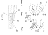
- an apparatus indicated generally by the reference 31 for forming a sector of a lip skin of an aircraft nacelle has a die plate 6 having a cast or machined surface supported by an additional cast or machined structure, not shown that transfers the force from the die plate 6 to a press system.
- the surface of the die plate 6 is made from a conic section with linear extensions on each side.
- the die plate surface is designed to ensure an even draw over the surface of a punch 12 while providing sufficient clearance to re-draw the internal surface using redraw ring sector 7.
- the shape of a cut out 16 in the centre of the die plate 6 is designed to match the shape of the punch 12 with a small clearance for the material blank thickness.
- the corners of the cut out 16 are rounded 17 to ensure sufficient material flow that also minimises wrinkling.
- the internal peripheral surface of the cutout 16 is rounded by a radius 14 to provide controlled material flow during the drawing operation.
- the re-draw ring sector 7 is movably mounted on the die plate 16 of the retaining arrangement 6, 8 facing a gap 51 for insertable movement into the gap 51.
- the redraw ring sector 7 is a semi arcuate member designed to draw the internal profile from the leading edge 3 to the inlet edge 2 while ensuring the blank 10 does not wrinkle or rip.
- the outer curved surface of the re-draw ring sector 7 is designed to match the internal profile of the punch 12 with clearance for the material thickness.
- the front of the re-draw ring sector 7 is rounded by radius 16 the size of which ensures that the blank 10 can re-draw around the ring sector 7 without ripping or wrinkling.
- the re-draw ring sector 7 can be driven by an integrated actuator system or by a series of cam dies from the main press.
- the blank holder 8 has a cast or machined surface to match the die plate 6.
- the blank holder 8 and die 6 are designed to match with clearance for the blank thickness.
- the main action of closing the blank holder 8 relative to the die 6 occurs in a vertical axis.
- the punch 12 comprises a punch sub-assembly having three main components, the internal support 11, punch 12 and internal grip 13.
- the internal support 11 supports the punch 12 and the internal grip 13.
- the external surface of the punch 12 is designed to match the internal surface of the inlet cowl up to 120 degree segments.
- the punch 12 is extended on each side beyond the 120 degree segment in order to minimise the distortion along the edges of the part.
- the punch axial length is extended beyond the trailing edge to minimise final part distortion.
- the internal grip 13 has an arcuate profile that matches the internal profile of the punch 12.
- the internal grip 13 can move in the axial direction 18 with a resisting force provided by an integrated actuation system or mechanical spring 71.
- the blank 10 is a profiled sheet material.
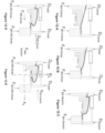
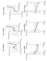
- the processing steps are shown in Figures 5A to 5F and the corresponding changes in the blank shape are shown in Figures 6A to 6F .
- the blank 10 is placed between the blank holder 8 and die 6 before closing see Figure 5A and 6A .
- the die 6 or blank holder 8 is then closed vertically.
- a force FBH-Clamp is applied to the blank holder 8 by a die cushion action from the die 6 or an additional actuation system in a preferably vertical direction 18.
- the blank 10 is then drawn over the punch sub-assembly 9 by a distance D Draw as shown in Figures 5B while applying the force FBH-Draw.
- the blank 10 is free to draw in a controlled fashion from between the blank holder 8 and die 6 through the die cavity 16 as shown in Figure 5B and 6B .
- the blank 10 is then sheared along two axial lines see Figure 6D either in the tooling system or by removing the part from the tooling system and using either a manual or CNC cutting process. If the material removal process occurs outside the tool system, the blank is then placed back into the tooling system see Figure 6D and a load F BH rr Draw is applied.
- the blank holder 8 and die 6 remain in the D Fixed position while the load FBH-RR Draw is maintained see Figure 5D while the re-draw ring sector 7 is forced into the punch sub-assembly 9 by a distance DRR-Draw under a spring force load of F RR-Draw see Figure 5D .
- the re-draw ring sector 7 contacts the internal grip 13 with a reaction load FRR-Stretch which then reduces or eliminates the draw of the blank 10 between the internal grip 13 and the re-draw ring sector 7.
- the blank 10 is then formed under tension for the remainder of the motion DRR-Stretch while the forces FBH RR draw and FRR-Stretch are maintained see Figure 5E .
- the blank 10 shape is then that shown in see Figure 6E .
- the blank 10 is then removed by removing all holding forces, retracting the re-draw ring sector 7 and lifting the die 6 clear as shown in see Figure 6F .
- the blank 10 is then trimmed using either a manual or CNC cutting process see Figure 6F .
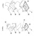
- the retaining arrangement 23 has a blank holder 28 and a die 26.
- the die 26 has a movable portion 27 capable of being moved relative to the remainder of the die 26 when the blank 10 is clamped between the die 26 and blank holder 28.
- the movable portion 27 of the die 26 is located proximal to the leading edge of the die 26.
- leading edge of the die 26 we mean the edge of the die 26 proximal to the leading edge of the punch 32 and the leading edge of the blank 10 to be formed into a sector 22 of an annular component such as a lipskin.
- the movable portion 27 of the die 26 is movable by powered actuation members 29, such as hydraulic rams.
- the powered actuation members 29 are operable between the movable portion 27 and another portion 30 of the die 26, mutually opposing the movable portion 27.
- the movable portion 27 of the die 26 provides one part of the cooperating forming arrangement indicated generally by reference numeral 33.
- the movable portion 27 of the die 26 is movable in a direction from the leading edge to the inlet edge of the sector 22 see figure 13F of the annular component for draw forming this part of the blank.
- the die 26 has a die plate 34, see figure 11 and a support member 35 see Figure 10 around all or part of the perimeter of the die plate 34.
- the support member 35 is provided by a four walled open top box with reinforced corners and walls.
- the support member 35 provides structural support for the die plate 34 for transferring the clamping forces being applied through the die 26 to clamp the blank 10 between the die 26 and the blank holder 28 and for absorbing the actuation forces being applied by the actuation members 29 through the walls of the support member 35 to allow the movable portion 27 of the die 26 to be activated.
- the punch 32 has an internal grip 39.
- the internal grip 39 has an arcuate profile that matches the internal profile of the forming punch 32.
- the internal grip 39 can move in the axial direction with a resisting force provided by an integrated actuation system or biasing means such as one or more springs 36.
- the internal grip 39 provides the second part of the cooperating forming arrangement 33 working together with the movable portion 27 of the die 26.
- the internal grip 39 is alignable with the movable portion 27 of the die 26 as the punch 32 forms the trailing edge to the leading edge of the lipskin sector.
- a cut out 46 in the centre of the die plate 26 is designed to match the shape of the punch 32 with a small clearance for the material blank 10 thickness.
- the corners of the cut out 46 are rounded 47 to ensure sufficient material flow that also minimises wrinkling.
- the internal peripheral surface of the cutout 46 is rounded by a radius 44 to provide controlled material flow during the drawing operation.
- Both the upper and the lower edges of the leading edge of the movable portion 27 of the die 26 have a radius 44.
- arrows Rd and Ad on Figure 12E indicate the radial and axial directions respectively.
- FIG. 12A to 12E The processing steps are shown in Figures 12A to 12E and the corresponding changes in the blank shape are shown in Figures 13A to 13F .
- the blank 10 is placed between the blank holder 28 and die 26 before closing see Figure 12A and 13A .
- the die 26 or blank holder 28 is then closed vertically.
- a force FBH-Clamp is applied to the blank holder 28 by a die cushion action from the die 26 or an additional actuation system in a preferably vertical direction 18.
- the blank 10 is then drawn over the punch 32 by a distance D Draw as shown in Figures 12B while applying the force FBH-Draw.
- the blank 10 is free to draw in a controlled fashion from between the blank holder 28 and die 26 through the die cavity 46 as shown in Figure 12B and 13B .
- the blank 10 is then sheared along two axial lines see Figure 13D either in the tooling system or by removing the part from the tooling system and using either a manual or CNC cutting process. If the material removal process occurs outside the tool system, the blank is then placed back into the tooling system see Figure 13D and a load F BH RR Draw is applied.
- the blank holder 28 and die 26 remain in the D Fixed position while the load FBH-RR Draw is maintained see Figure 13D while the movable portion 27 of the die 26 is forced into the punch 32 by a distance DRR-Draw under a spring force load of F RR-Draw see Figure 12D .
- the movable portion 27 of the die 26 contacts the internal grip 39 with a reaction load FRR-Stretch which then reduces or eliminates the draw of the blank 10 between the internal grip 39 and the movable portion 27 of the die 26.
- the blank 10 is then formed under tension for the remainder of the motion DRR-Stretch while the forces FBH RR draw and FRR-Stretch are maintained see Figure 12E .
- the blank 10 shape is then that shown in see Figure 13E .
- the blank 10 is then removed by removing all holding forces, retracting the movable portion 27 of the die 26 and lifting the die 26 clear as shown in see Figure 13F .
- the blank 10 is then trimmed using either a manual or CNC cutting process see Figure 13F .
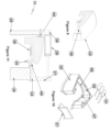
- the apparatus has two separate draw forming tools, the first tool 51 having similar components to the components illustrated in Figures 7 to 13 .
- the first tool 51 has blank holder 52 and die 53 for retaining a blank 54 there between with alignable cutouts 56, 57 respectively for receiving punch 55.
- the function of the tool is clearly illustrated in Figures 18A to 18C and will be described in greater detail below.
- a second tool is used as illustrated in Figures 16 and 17 and in Figures 18D to 18F , no cooperating forming arrangement is included in the first tool.
- the second tool illustrated in Figures 16 and 17 comprises a sector of a punch 65 formed for receiving the partially formed lip skin sector formed by the tool illustrated in Figure 14 and 15 .
- the form of the arcuate leading edge of the punch 65 corresponds closely to the form of the leading edge of the punch 55 so as to neatly accommodate the partially formed lip skin sector.
- a clamping ring sector 66 has an interior curved surface formed for nesting engagement with the exterior curved surface of the punch 65 with clearance for the thickness of the blank 10.
- a cooperating forming arrangement in the form of a pair of cooperating gripping ring sectors 67, 68 are provided for draw forming the blank from the leading edge to the inlet edge of the lip skin sector.
- Gripping ring sector 68 is an internal gripping ring sector 68 having an external curved surface formed for engaging the internal surface of the blank 10.
- Gripping ring sector 67 is an external gripping ring sector 67 having an internal curved surface formed for engaging the external surface of the blank 10.
- Gripping ring sector 67 has an interior curved surface formed for nesting engagement with the exterior curved surface of the gripping ring sector 68 with clearance for the thickness of the blank 10.
- the operator actuates a powered actuation system to move the griping ring sector 68 into engagement with the blank 10 and then moves the gripping ring sector 67 into engagement with the blank.
- the leading edge of the gripping ring sector 67 is radiused to allow the blank 10 to flow through and around the leading edge during the redraw forming process.
- the processing steps are shown in Figures 18A to 18F .
- the blank 10 is placed between the blank holder 52 and die 53 before closing.
- the die 53 or blank holder 52 is then closed vertically.
- a force FBH-Clamp is applied to the blank holder 52 by a die cushion action from the die 53 or an additional actuation system in a preferably vertical direction 18.
- the blank 10 is then drawn over the punch 52 by a distance D Draw as shown in Figures 18B while applying the force FBH-Draw.
- the blank 10 is free to draw in a controlled fashion from between the blank holder 52 and die 53 through the die cavity 57 as shown in Figure 18B .
- the blank 10 is then sheared along two axial lines either in the tooling system or by removing the part from the tooling system and using either a manual or CNC cutting process.
- the blank is then placed into the second tooling system see Figure 18D and a load F BH RR Draw is applied.
- the blank holder 52 and die 53 remain in the D Fixed position while the load FGrip-RR Draw is applied to the gripping ring sectors 67, 68 see Figure 13D while the gripping ring sectors 67, 68 are forced into the punch 65 by a distance DRR-Draw under gripping force load of F Grip RR-Draw see Figure 18E .
- a stretching load Fstretch RR draw is applied to the gripping ring sectors 67, 68 which then reduces or eliminates the draw of the blank 10 between the gripping ring sectors 67, 68.
- the blank 10 is then formed under tension for the remainder of the motion DRR-Stretch while the forces FBH RR stretch and F Grip RR-Stretch are maintained see Figure 18F .
- the blank 10 is then removed by removing all holding forces, retracting the gripping ring sectors 67, 68 and lifting the clamping ring sector and the gripping ring sector clear.
- the blank 10 is then trimmed using either a manual or CNC cutting process.
- the apparatus has a separate aft re-draw forming tool 70, 73 and a leading edge re-draw tool 71, 72 having similar components to the components 67, 68 illustrated in Figures 16 and 17 .
- the leading edge re-draw tool 71, 72 has blank holder 72 and die 71 for retaining a blank 94 there between.
- the aft re-draw forming tool 70, 73 has two arcuate plates 70, 73 formed for gripping the blank there between.
- a gap is provided between re-draw forming tool 70, 73 and leading edge re-draw tool 71, 72 for receiving punch 69.
- the function of the tool is clearly illustrated in Figures 20 :C to 20:G and will be described in greater detail below.
- a second tool is used as illustrated in Figures 19 and 20 and in Figures 20 : D to 20:F, no additional cooperating forming arrangement is included.
- the fourth embodiment of apparatus illustrated in Figures 19 and 20 comprises a sector of a punch 69 formed for receiving the partially formed lip skin sector formed by the tool illustrated in Figure 14 and 15 .
- the form of the arcuate leading edge of the punch 69 corresponds closely to the form of the leading edge of the punch 55 so as to neatly accommodate the partially formed lip skin sector.
- an operator removes the partially formed blank from the first tool after the blank has been formed as illustrated in Figures 20 :A to 20: C.
- the trailing edge of this partially formed blank is trimmed leaving a first bent section bent at approximately 90 degrees relative to the trailing end of the partially formed annular sector.
- a second shorter bent section is bent from the end of the first bent section of the trimmed portion, the second short bent section being bent back towards the leading edge of the partially formed lip skin sector.
- This trimmed partially formed lip skin sector is set onto the punch 69.
- the operator actuates a powered actuation system to bring the aft re-draw forming tool 70, 73 and the blank 94 into engagement with each other.
- the first and second bent sections of the trailing edge of the partially formed lip skin sector is located between the two arcuate plates 70, 73 and as the plates 70, 73 are closed together by a powered actuator the bent sections are clamped and gripped there between.
- An arcuate groove is formed in one of the interior gripping faces of the arcuate gripping plates and this groove is formed for receiving the short bent section of the trimmed portion of the partially formed lip skin sector. This provides a secondary locking function between the bent sections of the tailing edge of the partially formed lipskin sector and the gripping plates 70, 73 to further enhance the gripping action of the arcuate gripping plates 70, 73.
- a leading edge re-draw tool 71, 72 in the form of a pair of cooperating gripping ring sectors 71, 72 are provided for draw forming the partially formed lip skin sector from the leading edge to the inlet edge of the lip skin sector.
- Gripping ring sector 72 is an internal gripping ring sector 72 having an external curved surface formed for engaging the internal surface of the partially formed lip skin sector 94.
- Gripping ring sector 71 is an external gripping ring sector 71 having an internal curved surface formed for engaging the external surface of the partially formed lip skin sector 94.
- Gripping ring sector 71 has an interior curved surface formed for nesting engagement with the exterior curved surface of the gripping ring sector 72 with clearance for the thickness of the partially formed lip skin sector 94.
- the operator actuates a powered actuation system to move the griping ring sector 72 into engagement with the partially formed lip skin sector 94 and then moves the gripping ring sector 71 into engagement with the partially formed lip skin sector 94.
- the leading edge of the gripping ring sector 71 is radiused to allow the partially formed lip skin sector 94 to flow through and around the leading edge during the redraw forming process.
- the processing steps are shown in Figures 20 :A to 20F.
- the blank 94 is placed between the blank holder 52 and die 53 before closing, see Figure 14 and 15 .
- the die 53 or blank holder 52 is then closed vertically.
- a force FBH-Clamp is applied to the blank holder 52 by a die cushion action from the die 53 or an additional actuation system in a preferably vertical direction 18.
- the blank 94 is then drawn over the punch 52 by a distance D Draw as shown in Figures 20B while applying the force FBH-Draw.
- the blank 94 is free to draw in a controlled fashion from between the blank holder 52 and die 53 through the die cavity 57 as shown in Figure 20B .
- the blank 10 is then sheared along two axial lines either in the tooling system or by removing the part from the tooling system and using either a manual or CNC cutting process.
- the blank is then placed into the second tooling system see Figure 20 :D and a load F Grip RR Draw is applied between blank holder 72 and die 71 of the leading edge re-draw tool 71, 72.
- a load F aftgrip-RR-Draw is placed on the aft re-draw forming tool 70, 73.
- the two arcuate plates 70, 73 of aft re-draw forming tool 70, 73 remain in the fixed position while the load FGrip-RR Draw is applied to the blank holder 72 and die 71 of the leading edge re-draw tool 71, 72 see Figure 20 :D while the blank holder 72 and die 71 of the leading edge re-draw tool 71, 72 are forced into the punch 69 by a distance DRR-Draw under gripping force load of F Grip RR-Draw see Figure 20 :E.
- a stretching load F Grip RR stretch is applied to the blank holder 72 and die 71 of the leading edge re-draw tool 71, 72 which then reduces or eliminates the draw of the blank 10 between blank holder 72 and die 71 of the leading edge re-draw tool 71, 72.
- a load F aftgrip-RR-stretch is placed on the aft re-draw forming tool 70, 73.
- the two arcuate plates 70, 73 of aft re-draw forming tool 70, 73 are simultaneously moved a distance D RR-Stretch while the load FGrip-RR Stretch is applied to the blank holder 72 and die 71 of the leading edge re-draw tool 71, 72 see Figure 20 :F.
- the blank 94 is then formed under tension for the remainder of the motion DRR-Stretch while the forces are maintained.
- the blank 10 is then removed by removing all holding forces, retracting the die 71 of the leading edge re-draw tool 71 and lifting the arcuate plate 70 clear of the arcuate plate 73.
- the blank 10 is then trimmed using either a manual or CNC cutting process.
Landscapes
- Engineering & Computer Science (AREA)
- Mechanical Engineering (AREA)
- Aviation & Aerospace Engineering (AREA)
- Shaping Metal By Deep-Drawing, Or The Like (AREA)
Description
- This invention relates to a lip skin sector and to a method and apparatus for forming a lip skin sector. A lip skin is the mechanical component surrounding the inlet opening of an aircraft nacelle. The nacelle generally has a thin, aerodynamically shaped metal skin covering the jet engine of the aircraft. The lip skin is generally comprised of a single piece or multiple sectors and the main features of the lip skin are a smooth outer trailing edge which must be free from irregularities and discontinuities to reduce drag and to avoid the creation of turbulence. An inner inlet edge which is typically shaped to attenuate noise from the engine by shielding fan noise and to guide the flow of air into the engine, and a leading edge or lip, which provides a smooth transition between the outer trailing edge and the inner inlet edge while creating a small frontal area to reduce drag.
- The complex three dimensional compound curvature shape of the lip skin typically requires a complex multi-stage forming process, often requiring intermediate heat treatments. Typically lip skins are produced by multiple stage deep drawings or spin forming processes, requiring complex and costly tooling and time consuming multi-step processing with intermediate heat treatments. Due to aerodynamic and noise considerations, it is particularly desirable to extend the outer trailing edge of the lip skin as far as possible, known as extended trailing edges wherein the axial length of the outer trailing edge of the lip skin can be much greater than axial length of the inner inlet edge. Known deep drawing processes are unsuitable for the manufacture of such extended trailing edges.
WO 2014/118300 A1 , forming the basis for the preamble ofclaim 1, relates to a sector of an annular component. - A typical lip skin of an extended inlet cowl is illustrated in
Figure 1 of the drawings. The main features of an inlet cowl are the: - 1. Trailing edge;
- 2. Inlet edge;
- 3. Leading edge;
- 4. Arc or sector definition; and,
- 5. Centre line extending in the axial direction
- The method and apparatus of the present invention can be used for standard inlet cowl sectors where the axial distance between
features features features 1 to 3 is much greater than that fromfeatures 2 to 3. The overall size of the sector is determined by the blank size referred to asItem 10 in theFigures 2 and 3 . - One object of the present invention is to provide a sector of a lip skin and a method and apparatus for forming a sector of a lip skin with an extended outer portion to increase the extent of laminar flow over the outer surface of the nacelle and thus remove any flow interruptions. However, the present invention is equally applicable to standard inlet cowl sectors.
- Accordingly, the present invention provides an apparatus for forming a sector of an annular component as claimed in
claim 1. - Ideally, the retaining means is adapted to create a continuous clamping boundary enclosing the accessible part of the blank to be formed by the punch.
- Preferably, the retaining means forms a frame enclosing the accessible part of the blank to be formed by the punch.
- Ideally, the retaining means forms a continuous frame enclosing the part of the blank to be formed by the punch.
- Advantageously, the use of a clamping boundary enclosing the part of the blank to be formed means that the blank will draw in a substantially uniform manner through this clamping boundary as the punch comes into contact with the blank. This provides a major advantage over existing technologies for forming a sector of an annular component such as a lip skin of a nacelle where only leading edges and trailing edges of the blank sector are gripped in the prior art forming processes. In the main, it prevents warping along the edges of the blank sector that are not gripped. This reduces the amount of manual work required to finish the formed sector of the lip skin and also reduces the risk of material deformation or degradation as a result of warping or wrinkling along the edges.
- Ideally, the cooperating forming means are operable as the retaining means and the punch are held in a fixed position relatively.
- Preferably, the cooperating forming means are operable in combination with the retaining means and the punch.
- Ideally, the cooperating forming means are adjustable in an axial direction defined by a centre-line.
- Preferably, the cooperating forming means are adjustable in a direction from the leading edge to the inlet edge of the formed sector.
- Preferably, the apparatus comprises actuation means for facilitating radial movement of the punch and/or retaining means.
- Ideally, the apparatus comprising actuation means for facilitating axial movement of the cooperating forming means along at least part of its travel.
- Ideally, the retaining means being adapted to define a gap for facilitating location of the punch.
- In use, the blank is formed into a sector of an annular component such as an inlet cowl/lip skin of an aircraft nacelle in a two stage forming process.
- In a second embodiment of the invention, at least part of the retaining means is also capable of operating as at least part of the cooperating forming means for draw forming the sector of the annular component from the leading edge to the inlet edge.
- Preferably, the retaining means comprises a blank holder and a die.
- Ideally, at least part of the blank holder has an external surface contour corresponding to the surface contour of a formed sector mountable thereon.
- Preferably, the die is a die plate.
- Ideally, the die plate has an internal surface contour corresponding to the surface contour of a formed sector mountable between the blank holder and the die.
- Ideally, the external surface contour of the blank holder and the internal surface contour of the die correspond as closely as possible to the surface contour of the formed sector of the annular component. Advantageously, this means that the forces being applied to the blank from the relative radial movement of the retaining means and the punch, as the punch comes into contact with the blank are as evenly distributed as possible. This means that the flow of blank material from between the blank holder and die will also be as uniform as possible. Again, this mitigates as far as possible the risk of deformation or damage to the material properties as a result of uneven strains applied by the forming tools to the material.
- Ideally, at least part of the die plate has the shape of an outer wall of a frusto conical body sectioned at or about its longitudinal axis.
- Preferably, the surface of the die plate contactable with the blank is cast or machined.
- Preferably, the die plate is supported by an additional cast or machined structure that transfers the force from the die plate to the press system.
- Ideally, the die plate surface for engaging the blank is conically contoured. Advantageously, the die plate surface is designed to ensure an even draw over the surface of the punch while providing sufficient clearance to re-draw the internal surface using the cooperating forming means.
- Preferably, the die plate has linear extensions on each side.
- Preferably, the die plate has a cut out.
- Ideally, the cut out is in the centre of the die. Advantageously, the central location of the cutout allows a uniform amount of material to be clamped around the cutout thereby ensuring an even draw of blank material around the punch.
- Preferably, the shape of the cut out is designed to match the shape of the punch with a small clearance for the blank material thickness.
- Preferably, the corners of the cut out are rounded. Advantageously, this ensures sufficient material flow which also minimises wrinkling.
- Ideally, at least part of the internal peripheral surface of the cut out is rounded by a radius for providing controlled material flow during the drawing operation.
- Preferably, the boundary between the internal surface of the die plate and the part of the internal peripheral surface of the cutout proximal to the blank is rounded by a radius for providing controlled material flow during the draw forming operation.
- In the second embodiment, the retaining means comprises a blank holder and a die.
- In the second embodiment, the die has a movable portion capable of being moved relative to the remainder of the die when the blank is clamped between the die and blank holder.
- In the second embodiment, the movable portion of the die is located proximal to the leading edge of the die. By leading edge of the die we mean the edge of the die proximal to the leading edge of the punch and the leading edge of the blank to be formed into a sector of an annular component such as a lipskin.
- In the second embodiment, the movable portion of the die is movable by powered actuation means.
- In the second embodiment, the powered actuation means is operable between the movable portion and another portion of the die.
- In the second embodiment, the movable portion of the die provides a part of the cooperating forming means.
- In the second embodiment, the movable portion of the die is movable in a direction from the leading edge to the inlet edge of the sector of the annular component for draw forming this part of the blank.
- In the second embodiment, the die comprises a die plate and a support means around all or part of the perimeter of the die plate. Advantageously, the support means provides structural support for the die plate for transferring the clamping forces being applied though the die to clamp the blank between the die and the blank holder and for absorbing the actuation forces being applied through the support means to allow the movable portion of the die to be activated.
- In the second embodiment, all or part of clamping surfaces of the movable portion of the die and the mutually opposing clamping surface of the blank holder are planar, most preferably horizontal planar clamping surfaces.
- In the second embodiment, the punch comprises an internal grip.
- In the second embodiment, the internal grip has an arcuate profile that matches the internal profile of the forming punch.
- In the second embodiment, the internal grip can move in the axial direction with a resisting force provided by an integrated actuation system or biasing means such as one or more springs.
- In the second embodiment, the internal grip provides the second part of the cooperating forming means working together with the movable portion of the die.
- In the second embodiment, the internal grip is alignable with the movable portion of the die as the punch forms the trailing edge to the leading edge of the lipskin sector.
- Ideally, the punch has an outer surface contour and a forming end shaped to correspond to the finished shape of the profile of the sector of the annular component from the trailing edge to the inlet edge.
- Ideally, the annular component is a lip skin for an aircraft nacelle.
- While composite materials can be used for many parts of the nacelle, the lip skin must generally be made from a metal, such as aluminum or titanium, to be able to withstand impacts upon the leading edge or lip thereof. The titanium is also useful in view of recently legislated stringent de-icing requirements requiring higher temperatures at the nacelle leading edge.
- Preferably, the forming end of the punch has an arcuate shape.
- Preferably, the punch has an external surface shaped to provide the profile of the formed sector of a lip skin.
- Ideally, the external surface of the punch is optimized for springback.
- Preferably, the external surface of the punch has a high surface finish. Advantageously, the high surface finish value reduces friction during forming.
- Ideally, the actuation means is a hydraulic or electromechanical actuation system.
- Preferably, the punch and/or the retaining means is mechanically coupled to the actuation means
- Ideally, the blank holder has a cast or machined surface to match the surface of the die.
- Preferably, the blank holder and die are designed to match with clearance for the blank thickness.
- Ideally, the blank holder has the shape of a frusto conical body sectioned at or about its longitudinal axis.
- Preferably, the surface of the blank holder contactable with the blank is cast or machined.
- Ideally, the blank holder surface for engaging the blank is conically contoured. Advantageously, the blank holder surface is designed to ensure an even draw over the surface of the punch while providing sufficient clearance to re-draw the internal surface using the cooperating forming means.
- Ideally, the blank holder and/or the die is initially movable for clamping the blank, most preferably in a vertical axis. Advantageously, this ensures an even contact pressure over the entire blank surface. This is one important aspect of ensuring even flow of blank material during the draw forming process.
- Ideally, the blank holder has a cutout defining the gap and being formed for alignment with the cutout of the die in use.
- Preferably, the blank holder cutout/gap is formed for receiving the punch.
- Preferably, the cooperating forming means comprises a re-draw ring sector being movably mounted on the retaining means facing the punch for insertable movement into the punch.
- Ideally, the retaining means has a cavity formed for receiving the re-draw ring sector opening towards the punch.
- In use, the redraw ring sector is designed to draw the internal profile of the sector of the annular component from the leading edge to the inlet edge while ensuring the blank does not wrinkle or rip.
- Preferably, the outer curved surface of the re-draw ring sector is designed to match the internal profile of the punch with clearance for the material thickness.
- Ideally, the internal curved surface of the re-draw ring sector is designed to match the surface of the blank holder.
- Preferably, the leading edge of the re-draw ring sector between the outer curved surface and the internal curved surface is rounded by a radius. Advantageously, the size of the radius ensures that the blank can re-draw around the ring without ripping or wrinkling.
- Ideally, the re-draw ring sector is driven by an integrated actuator system or by a series of cam dies from a main press.
- Ideally, the punch comprises a punch sub-assembly.
- Preferably, the punch sub-assembly comprises an internal support, the forming punch and an internal grip.
- Ideally, the forming punch and the internal support define an axial arcuate channel opening towards the redraw ring sector.
- Preferably, the punch has an axial arcuate channel opening towards the redraw ring sector.
- Ideally, the punch has an internal grip in the axial arcuate channel.
- Preferably, the axial arcuate channel is alignable with the redraw ring sector.
- Preferably, the axial arcuate channel is formed for receiving at least part of the redraw ring sector for forming the sector of the annular component between the leading edge and the inlet edge.
- Ideally, the internal support supports the forming punch and the internal grip.
- Preferably, the external surface of the forming punch is designed to match the internal surface of a sector of the inlet cowl.
- Ideally, the forming punch is extended on each side beyond the segment in order to minimise the distortion along the edges of the part.
- Preferably, the forming punch axial length is extended beyond the trailing edge of the desired sector to minimise final part distortion.
- Ideally, the internal grip has an arcuate profile that matches the internal profile of the forming punch.
- Preferably, the internal grip can move in the axial direction with a resisting force provided by an integrated actuation system or biasing means such as springs.
- Preferably, the blank is produced from a single sheet or several joined sheets. The joint is normally achieved using the friction stir welding process although linear friction and other high formability high quality welding processes can also be used to form the frusto-conical blank.
- Ideally, the profile of the punch is designed to match the profile of the lip skin with allowance for springback where required.
- Preferably, the trailing edge of the punch has a radius. Advantageously, the size of the radius ensures that the blank can draw around the punch without ripping or wrinkling.
- In a third embodiment of apparatus for forming lip skin sector, the apparatus comprises two separate draw forming tools.
- Ideally, the first tool has a blank holder and die for retaining a blank there between with alignable cutouts respectively for receiving punch. In view of the fact that a second tool is used, no cooperating forming arrangement is included in the first tool.
- Preferably, a second tool comprises a sector of a punch formed for receiving the partially formed lip skin sector, the form of the arcuate leading edge of the punch sector corresponding closely to the form of the leading edge of the punch of the first tool so as to neatly accommodate the partially formed lip skin sector.
- Preferably, a clamping ring sector has an interior curved surface formed for nesting engagement with the exterior curved surface of the punch with clearance for the thickness of the blank. In use an operator removes the partially formed blank from the first tool and sets it onto the punch of the second tool. The operator actuates a powered actuation system to move the clamping ring sector and/or punch so as to bring the blank into engagement with the clamping ring sector.
- Ideally, a cooperating forming arrangement in the form of a pair of cooperating gripping ring sectors are provided for draw forming the blank from the leading edge to the inlet edge of the lip skin sector.
- Preferably, a first gripping ring sector is an internal gripping ring sector having an external curved surface formed for engaging the internal surface of the blank.
- Ideally, a second gripping ring sector is an external gripping ring sector having an internal curved surface formed for engaging the external surface of the blank.
- Ideally, external gripping ring sector has an interior curved surface formed for nesting engagement with the exterior curved surface of the internal gripping ring sector with clearance for the thickness of the blank. The operator actuates a powered actuation system to move the internal griping ring sector into engagement with the blank and then moves the external gripping ring sector into engagement with the blank. The leading edge of the gripping ring sector is radiused to allow the blank to flow through and around the leading edge during the redraw forming process.
- In a fourth embodiment of apparatus for forming lip skin sector, the apparatus comprises a second arrangement of two separate draw forming tools.
- Ideally, the first tool has a blank holder and die for retaining a blank there between with alignable cutouts respectively for receiving punch. In view of the fact that a second tool is used, no cooperating forming arrangement is included in the first tool.
- In the fourth embodiment, and in the invention as claimed in
claim 1, the apparatus has a separate aft re-draw forming tool and a leading edge re-draw tool. - Ideally, the leading edge re-draw tool has a blank holder and die for retaining a blank there between.
- Preferably, the aft re-draw forming tool has two arcuate plates formed for gripping the trailing edge of the blank there between.
- Ideally, a gap is provided between re-draw forming tool and leading edge re-draw tool for receiving a further punch.
- The fourth embodiment of apparatus comprises a sector of a punch formed for receiving the partially formed lip skin sector formed by the first tool.
- Ideally, the form of the arcuate leading edge of the punch corresponds closely to the form of the leading edge of the punch so as to neatly accommodate the partially formed lip skin sector.
- In use an operator removes the partially formed blank from the first tool after the blank has been formed.
- Ideally, the trailing edge of this partially formed blank is trimmed leaving a first bent section bent at approximately 90 degrees relative to the trailing end of the partially formed annular sector.
- Preferably, the trailing edge is further formed to leave a second shorter bent section bent from the end of the first bent section of the trimmed portion, the second short bent section being bent back towards the leading edge of the partially formed lip skin sector.
- This trimmed partially formed lip skin sector is set onto the
punch 6. The operator actuates a powered actuation system to bring the aft re-draw forming tool and the blank into engagement with each other. The first and second bent sections of the trailing edge of the partially formed lip skin sector is located between the two arcuate plates and as the plates are closed together by a powered actuator the bent sections are clamped and gripped there between. - Ideally, one of the interior gripping faces of the arcuate gripping plates an arcuate groove formed therein and this groove is formed for receiving the short bent section of the trimmed portion of the partially formed lip skin sector. Advantageously, this provides a secondary locking function between the bent sections of the tailing edge of the partially formed lipskin sector and the gripping plates to further enhance the gripping action of the arcuate gripping plates.
- Ideally, the second arrangement of draw forming tools has a leading edge re-draw tool in the form of a pair of cooperating gripping ring sectors provided for draw forming the partially formed lip skin sector from the leading edge to the inlet edge of the lip skin sector.
- Preferably, one gripping ring sector is an internal gripping ring sector having an external curved surface formed for engaging the internal surface of the partially formed lip skin sector.
- Ideally, the other gripping ring sector is an external gripping ring sector having an internal curved surface formed for engaging the external surface of the partially formed lip skin sector.
- Preferably, the external gripping ring sector has an interior curved surface formed for nesting engagement with the exterior curved surface of the gripping ring sector with clearance for the thickness of the partially formed lip skin sector.
- In use, the operator actuates a powered actuation system to move the internal griping ring sector into engagement with the partially formed lip skin sector and then moves the external gripping ring sector into engagement with the partially formed lip skin sector or vice versa.
- Ideally, the leading edge of the external gripping ring sector is radiused to allow the partially formed lip skin sector to flow through and around the leading edge during the redraw forming process.
- Accordingly, the present invention provides a method of forming a sector of an annular component as claimed in
claim 10. - Ideally, the method comprising the steps of clamping at least part of a blank along a continuous clamping boundary in a retaining means so as to leave a portion of the blank exposed within the clamping boundary.
- Preferably, the method comprising clamping at least part of the blank along a clamping boundary in a retaining means enclosing the portion of the exposed blank.
- Ideally, the method comprising shearing the partly formed blank along two axial lines.
- Preferably, the method comprising radially moving the retaining means and/or the punch so that a redraw ring sector aligns with an arcuate channel of a punch and actuating the redraw ring sector so that it moves axially into the arcuate channel for engaging the blank and drawing the blank over the punch forming the sector of the inlet cowl from the leading edge to the inlet edge.
- In an alternative method step for draw forming the sector of the annular component from the leading edge to the inlet edge, the method comprising moving a movable portion of the die axially towards the remaining part of the die under powered actuation means. In this method, the movable part of the die acts as part of the cooperating forming means.
- Ideally, the method comprising placing the blank between a blank holder and die before closing the blank holder and die together.
- Preferably, the method comprising closing the die and applying a closing force to the blank holder and/or die during this closing stage.
- Preferably, the method comprising drawing the blank over the punch by a predetermined distance while maintaining the closing force. Advantageously, the blank is free to draw in a controlled fashion from between the blank holder and die through a die cavity.
- Ideally, the method comprising increasing the blank holder/die load upon reaching a predetermined draw depth while stretching the blank from all sides over the punch by a predetermined distance.
- Preferably, the method comprising limiting the drawing of the blank from between the blank holder and die during the stretching process. At this stage, the profile of the sector of the annular component from the leading edge to the trailing edge is formed.
- Ideally, the method comprising shearing the blank along two axial lines either in the tooling system or by removing the part from the tooling system and using either a manual or CNC cutting process. If the material removal process occurs outside the tool system, the blank is then placed back into the tooling system or into another tool.
- Ideally, the method comprising fixing the die in the locked position and forcing the redraw ring sector or movable portion of the die into a punch by a predetermined distance under a predetermined blank holder/die load.
- Preferably, the method comprising contacting the re-draw ring sector or movable portion of the die against an internal grip providing a reaction load which then reduces or eliminates the draw of the blank between the internal grip and the re-draw ring sector/movable portion of the die.
- Preferably, the method comprising removing the blank by removing all holding forces, retracting the re-draw ring sector and lifting the die clear.
- Ideally, the method comprising trimming the blank using either a manual or CNC cutting process.
- Ideally, the method comprising using a second draw forming tooling arrangement for the cooperating forming means.
- Preferably, the method comprising placing the partially formed lip skin sector into a second draw forming tooling arrangement and applying a draw load between a blank holder and die of a leading edge re-draw tool.
- The method further comprises placing a draw load on the aft re-draw forming tool.
- Preferably, the method comprising fixing the position of two arcuate plates of aft redraw forming tool remain while applying a draw load to the blank holder and die of the leading edge redraw tool while the blank holder and die of the leading edge re-draw tool are forced into the punch by a predetermined draw distance under a predetermined gripping force load.
- Ideally, the method further comprising applying a predetermined stretch load to the blank holder and die of the leading edge re-draw tool once the draw distance has been reached for reducing or eliminating the draw of the partially formed lip skin sector between blank holder and die of the leading edge re-draw tool.
- Preferably, the method further comprising placing a predetermined stretch load on the aft re-draw forming tool.
- Ideally, the method further comprising simultaneously moving the two arcuate plates of aft re-draw forming tool a predetermined stretch distance while the stretch load is applied to the blank holder and die of the leading edge re-draw tool.
- Ideally, the method comprising forming the blank under tension for the remainder of the stretch motion while the forces are maintained.
- Preferably, the method further comprising removing the blank by removing all holding forces, retracting the die of the leading edge re-draw tool and lifting the arcuate plate clear of the arcuate plate.
- According to a further aspect of the present invention, there is provided a sector of an annular component produced by the method outlined above.
- The invention will now be described with reference to the accompanying drawings, which show by way of example only three embodiments of an apparatus and method for forming a sector of an annular member such as a lip skin for a nacelle and the sector itself. In the drawings:-
-
Figure 1 is a sectional perspective view of an extended inlet cowl of a nacelle for an aircraft engine; -
Figure 2 is an exploded perspective view of an apparatus for forming a sector of a lip skin; -
Figure 3 is a sectional perspective view of a punch sub-assembly for forming a sector of a lip skin; -
Figure 4 is an exploded sectional perspective view of an apparatus for forming a sector of a lip skin; -
Figure 5 is a vertical section view of an apparatus for forming a sector of a lip skin; -
Figures 5A to 5E are vertical section views of the apparatus for forming a sector of a lip skin in first to fifth stages respectively of the forming process; - Figure 5F is a perspective view of the blank after the forming process and prior to trimming;
-
Figures 6A to 6E are perspective views of a sector of a frusto-conical blank at first to fifth stages respectively of the forming process; -
Figure 6F is a perspective view of a formed sector of inlet cowl after the forming process. -
Figure 7 is an exploded perspective view of a second embodiment of apparatus of the present invention; -
Figure 8 is a section of the perspective view ofFigure 7 ; -
Figure 9 is a detail section view of the punch assembly ofFigures 7 and 8 ; -
Figure 10 is an exploded detail view of a second embodiment of die plate and cooperating forming arrangement; -
Figure 11 is a sectional elevation view of the second embodiment of apparatus; -
Figures 12A to 12E are vertical section views of the apparatus for forming a sector of a lip skin in first to fifth stages respectively of the forming process; -
Figures 13A to 13E are perspective views of a sector of a frusto-conical blank at first to fifth stages respectively of the forming process; -
Figure 13F is a perspective view of a formed sector of inlet cowl after the forming process. -
Figure 14 is an exploded perspective view of a third embodiment showing a first tool of a two tool apparatus; -
Figure 15 is a section of the perspective view ofFigure 14 ; -
Figure 16 is an exploded perspective view of the third embodiment showing a second tool of the two tool apparatus; -
Figure 17 is a section of the perspective view ofFigure 16 ; -
Figures 18A to18C are vertical section views of the apparatus for forming a sector of a lip skin in first to third stages respectively carried out on the first tool of the two tool forming apparatus of the third embodiment; -
Figures 18D to 18F are vertical section views of the apparatus for forming a sector of a lip skin in fourth to sixth stages respectively carried out on the second tool of the two tool forming apparatus of the third embodiment; -
Figure 19 is an exploded perspective view of the fourth embodiment showing a second tool of the second arrangement of two tool apparatus; -
Figure 20 is a section of the perspective view ofFigure 19 ; -
Figures 20A to 20C are vertical section views of the apparatus for forming a sector of a lip skin in first to third stages respectively carried out on the first tool of the second arrangement of two tool forming apparatus of the fourth embodiment; and -
Figures 20D to 20G are vertical section views of the apparatus for forming a sector of a lip skin in fourth to sixth stages respectively carried out on the second tool of the second arrangement of two tool forming apparatus of the fourth embodiment. - Referring to the drawings and initially to
Figures 1 to 5F, there is shown an apparatus indicated generally by thereference 31 for forming a sector of a lip skin of an aircraft nacelle. Theapparatus 31 has adie plate 6 having a cast or machined surface supported by an additional cast or machined structure, not shown that transfers the force from thedie plate 6 to a press system. The surface of thedie plate 6 is made from a conic section with linear extensions on each side. The die plate surface is designed to ensure an even draw over the surface of apunch 12 while providing sufficient clearance to re-draw the internal surface using redrawring sector 7. The shape of a cut out 16 in the centre of thedie plate 6 is designed to match the shape of thepunch 12 with a small clearance for the material blank thickness. The corners of the cut out 16 are rounded 17 to ensure sufficient material flow that also minimises wrinkling. The internal peripheral surface of thecutout 16 is rounded by aradius 14 to provide controlled material flow during the drawing operation. - The
re-draw ring sector 7 is movably mounted on thedie plate 16 of the retainingarrangement gap 51 for insertable movement into thegap 51. The redrawring sector 7 is a semi arcuate member designed to draw the internal profile from theleading edge 3 to theinlet edge 2 while ensuring the blank 10 does not wrinkle or rip. The outer curved surface of there-draw ring sector 7 is designed to match the internal profile of thepunch 12 with clearance for the material thickness. The front of there-draw ring sector 7 is rounded byradius 16 the size of which ensures that the blank 10 can re-draw around thering sector 7 without ripping or wrinkling. There-draw ring sector 7 can be driven by an integrated actuator system or by a series of cam dies from the main press. - The
blank holder 8 has a cast or machined surface to match thedie plate 6. Theblank holder 8 and die 6 are designed to match with clearance for the blank thickness. The main action of closing theblank holder 8 relative to thedie 6 occurs in a vertical axis. - The
punch 12 comprises a punch sub-assembly having three main components, theinternal support 11, punch 12 andinternal grip 13. Theinternal support 11 supports thepunch 12 and theinternal grip 13. The external surface of thepunch 12 is designed to match the internal surface of the inlet cowl up to 120 degree segments. Thepunch 12 is extended on each side beyond the 120 degree segment in order to minimise the distortion along the edges of the part. The punch axial length is extended beyond the trailing edge to minimise final part distortion. Theinternal grip 13 has an arcuate profile that matches the internal profile of thepunch 12. Theinternal grip 13 can move in theaxial direction 18 with a resisting force provided by an integrated actuation system ormechanical spring 71. The blank 10 is a profiled sheet material. - The processing steps are shown in
Figures 5A to 5F and the corresponding changes in the blank shape are shown inFigures 6A to 6F . The blank 10 is placed between theblank holder 8 and die 6 before closing seeFigure 5A and6A . Thedie 6 orblank holder 8 is then closed vertically. During this closing stage a force FBH-Clamp is applied to theblank holder 8 by a die cushion action from thedie 6 or an additional actuation system in a preferablyvertical direction 18. The blank 10 is then drawn over thepunch sub-assembly 9 by a distance D Draw as shown inFigures 5B while applying the force FBH-Draw. The blank 10 is free to draw in a controlled fashion from between theblank holder 8 and die 6 through thedie cavity 16 as shown inFigure 5B and6B . - Upon reaching the draw depth D Draw the
blank holder 8 load is increased to FBH-Stretch seeFigure 5C while the blank 10 is stretched from all sides over thepunch sub-assembly 9 by a distance D Stretch. The blank 10 has minimal draw from between theblank holder 8 and die 6 during the stretching process seeFigure 5C . At this stage the inlet cowl profile from theleading edge 3 to the trailingedge 1 has been formed as shown inFigure 6C . - The blank 10 is then sheared along two axial lines see
Figure 6D either in the tooling system or by removing the part from the tooling system and using either a manual or CNC cutting process. If the material removal process occurs outside the tool system, the blank is then placed back into the tooling system seeFigure 6D and a load F BH rr Draw is applied. Theblank holder 8 and die 6 remain in the D Fixed position while the load FBH-RR Draw is maintained seeFigure 5D while there-draw ring sector 7 is forced into thepunch sub-assembly 9 by a distance DRR-Draw under a spring force load of F RR-Draw seeFigure 5D . - Once the distance DRR-Draw has been reached the
re-draw ring sector 7 contacts theinternal grip 13 with a reaction load FRR-Stretch which then reduces or eliminates the draw of the blank 10 between theinternal grip 13 and there-draw ring sector 7. The blank 10 is then formed under tension for the remainder of the motion DRR-Stretch while the forces FBH RR draw and FRR-Stretch are maintained seeFigure 5E . The blank 10 shape is then that shown in seeFigure 6E . The blank 10 is then removed by removing all holding forces, retracting there-draw ring sector 7 and lifting thedie 6 clear as shown in seeFigure 6F . The blank 10 is then trimmed using either a manual or CNC cutting process seeFigure 6F . - Referring to the drawings and now to
Figures 7 to 13 , there is shown a second embodiment of apparatus indicated generally by thereference numeral 21 for forming a sector of a standard lip skin and asector 22 of an extended trailing edge lip skin. In the second embodiment, the retaining arrangement 23 has ablank holder 28 and adie 26. Thedie 26 has amovable portion 27 capable of being moved relative to the remainder of the die 26 when the blank 10 is clamped between the die 26 andblank holder 28. Themovable portion 27 of the die 26 is located proximal to the leading edge of thedie 26. By leading edge of the die 26 we mean the edge of the die 26 proximal to the leading edge of thepunch 32 and the leading edge of the blank 10 to be formed into asector 22 of an annular component such as a lipskin. Themovable portion 27 of the die 26 is movable bypowered actuation members 29, such as hydraulic rams. Thepowered actuation members 29 are operable between themovable portion 27 and anotherportion 30 of the die 26, mutually opposing themovable portion 27. Themovable portion 27 of the die 26 provides one part of the cooperating forming arrangement indicated generally byreference numeral 33. Themovable portion 27 of the die 26 is movable in a direction from the leading edge to the inlet edge of thesector 22 seefigure 13F of the annular component for draw forming this part of the blank. - The
die 26 has adie plate 34, seefigure 11 and asupport member 35 seeFigure 10 around all or part of the perimeter of thedie plate 34. In the embodiment shown in the drawings, thesupport member 35 is provided by a four walled open top box with reinforced corners and walls. Advantageously, thesupport member 35 provides structural support for thedie plate 34 for transferring the clamping forces being applied through the die 26 to clamp the blank 10 between the die 26 and theblank holder 28 and for absorbing the actuation forces being applied by theactuation members 29 through the walls of thesupport member 35 to allow themovable portion 27 of the die 26 to be activated. Thepunch 32 has aninternal grip 39. Theinternal grip 39 has an arcuate profile that matches the internal profile of the formingpunch 32. Theinternal grip 39 can move in the axial direction with a resisting force provided by an integrated actuation system or biasing means such as one or more springs 36. Theinternal grip 39 provides the second part of the cooperating formingarrangement 33 working together with themovable portion 27 of thedie 26. Theinternal grip 39 is alignable with themovable portion 27 of the die 26 as thepunch 32 forms the trailing edge to the leading edge of the lipskin sector. - The shape of a cut out 46 in the centre of the
die plate 26 is designed to match the shape of thepunch 32 with a small clearance for the material blank 10 thickness. The corners of the cut out 46 are rounded 47 to ensure sufficient material flow that also minimises wrinkling. The internal peripheral surface of thecutout 46 is rounded by aradius 44 to provide controlled material flow during the drawing operation. Both the upper and the lower edges of the leading edge of themovable portion 27 of the die 26 have aradius 44. In terms of the meaning of radial and axial direction, arrows Rd and Ad onFigure 12E indicate the radial and axial directions respectively. - The processing steps are shown in
Figures 12A to 12E and the corresponding changes in the blank shape are shown inFigures 13A to 13F . The blank 10 is placed between theblank holder 28 and die 26 before closing seeFigure 12A and13A . The die 26 orblank holder 28 is then closed vertically. During this closing stage a force FBH-Clamp is applied to theblank holder 28 by a die cushion action from the die 26 or an additional actuation system in a preferablyvertical direction 18. The blank 10 is then drawn over thepunch 32 by a distance D Draw as shown inFigures 12B while applying the force FBH-Draw. The blank 10 is free to draw in a controlled fashion from between theblank holder 28 and die 26 through thedie cavity 46 as shown inFigure 12B and13B . - Upon reaching the draw depth D Draw the blank holder load is increased to FBH-Stretch see
Figure 12C while the blank 10 is stretched from all sides over thepunch 32 by a distance D Stretch. The blank 10 has minimal draw from between theblank holder 28 and die 26 during the stretching process seeFigure 12C . At this stage the inlet cowl profile from theleading edge 3 to the trailingedge 1 has been formed as shown inFigure 13C . - The blank 10 is then sheared along two axial lines see
Figure 13D either in the tooling system or by removing the part from the tooling system and using either a manual or CNC cutting process. If the material removal process occurs outside the tool system, the blank is then placed back into the tooling system seeFigure 13D and a load F BH RR Draw is applied. Theblank holder 28 and die 26 remain in the D Fixed position while the load FBH-RR Draw is maintained seeFigure 13D while themovable portion 27 of the die 26 is forced into thepunch 32 by a distance DRR-Draw under a spring force load of F RR-Draw seeFigure 12D . - Once the distance DRR-Draw has been reached the
movable portion 27 of the die 26 contacts theinternal grip 39 with a reaction load FRR-Stretch which then reduces or eliminates the draw of the blank 10 between theinternal grip 39 and themovable portion 27 of thedie 26. The blank 10 is then formed under tension for the remainder of the motion DRR-Stretch while the forces FBH RR draw and FRR-Stretch are maintained seeFigure 12E . The blank 10 shape is then that shown in seeFigure 13E . The blank 10 is then removed by removing all holding forces, retracting themovable portion 27 of thedie 26 and lifting the die 26 clear as shown in seeFigure 13F . The blank 10 is then trimmed using either a manual or CNC cutting process seeFigure 13F . - Referring to the drawings and now to
Figures 14 to 18 , there is shown a third embodiment of apparatus for forming lip skin sector. In the third embodiment, the apparatus has two separate draw forming tools, thefirst tool 51 having similar components to the components illustrated inFigures 7 to 13 . Thefirst tool 51 hasblank holder 52 and die 53 for retaining a blank 54 there between withalignable cutouts punch 55. The function of the tool is clearly illustrated inFigures 18A to 18C and will be described in greater detail below. In view of the fact that a second tool is used as illustrated inFigures 16 and 17 and inFigures 18D to 18F , no cooperating forming arrangement is included in the first tool. - The second tool illustrated in
Figures 16 and 17 comprises a sector of apunch 65 formed for receiving the partially formed lip skin sector formed by the tool illustrated inFigure 14 and 15 . The form of the arcuate leading edge of thepunch 65 corresponds closely to the form of the leading edge of thepunch 55 so as to neatly accommodate the partially formed lip skin sector. A clampingring sector 66 has an interior curved surface formed for nesting engagement with the exterior curved surface of thepunch 65 with clearance for the thickness of the blank 10. In use an operator removes the partially formed blank from the first tool and sets it onto thepunch 65. The operator actuates a powered actuation system to move theclamping ring sector 66 and/or punch 65 so as to bring the blank 10 into engagement with the clampingring sector 66. A cooperating forming arrangement in the form of a pair of cooperating grippingring sectors ring sector 68 is an internalgripping ring sector 68 having an external curved surface formed for engaging the internal surface of the blank 10. Grippingring sector 67 is an externalgripping ring sector 67 having an internal curved surface formed for engaging the external surface of the blank 10. - Gripping
ring sector 67 has an interior curved surface formed for nesting engagement with the exterior curved surface of thegripping ring sector 68 with clearance for the thickness of the blank 10. The operator actuates a powered actuation system to move thegriping ring sector 68 into engagement with the blank 10 and then moves thegripping ring sector 67 into engagement with the blank. The leading edge of thegripping ring sector 67 is radiused to allow the blank 10 to flow through and around the leading edge during the redraw forming process. - The processing steps are shown in
Figures 18A to 18F . The blank 10 is placed between theblank holder 52 and die 53 before closing. The die 53 orblank holder 52 is then closed vertically. During this closing stage a force FBH-Clamp is applied to theblank holder 52 by a die cushion action from the die 53 or an additional actuation system in a preferablyvertical direction 18. The blank 10 is then drawn over thepunch 52 by a distance D Draw as shown inFigures 18B while applying the force FBH-Draw. The blank 10 is free to draw in a controlled fashion from between theblank holder 52 and die 53 through thedie cavity 57 as shown inFigure 18B . - Upon reaching the draw depth D Draw the blank holder load is increased to FBH-Stretch see
Figure 18C while the blank 10 is stretched from all sides over thepunch 52 by a distance D Stretch. The blank 10 has minimal draw from between theblank holder 52 and die 53 during the stretching process seeFigure 18C . At this stage the inlet cowl profile from theleading edge 3 to the trailingedge 1 has been formed. - The blank 10 is then sheared along two axial lines either in the tooling system or by removing the part from the tooling system and using either a manual or CNC cutting process. The blank is then placed into the second tooling system see
Figure 18D and a load F BH RR Draw is applied. Theblank holder 52 and die 53 remain in the D Fixed position while the load FGrip-RR Draw is applied to thegripping ring sectors Figure 13D while thegripping ring sectors punch 65 by a distance DRR-Draw under gripping force load of F Grip RR-Draw seeFigure 18E . - Once the distance DRR-Draw has been reached a stretching load Fstretch RR draw is applied to the
gripping ring sectors gripping ring sectors Figure 18F . The blank 10 is then removed by removing all holding forces, retracting thegripping ring sectors - Referring to the drawings and now to
Figures 19 to 20 :G, there is shown a fourth embodiment of apparatus for forming a lip skin sector. In the fourth embodiment, the apparatus has a separate aftre-draw forming tool re-draw tool components Figures 16 and 17 . The leading edgere-draw tool blank holder 72 and die 71 for retaining a blank 94 there between. The aftre-draw forming tool arcuate plates re-draw forming tool re-draw tool punch 69. The function of the tool is clearly illustrated inFigures 20 :C to 20:G and will be described in greater detail below. In view of the fact that a second tool is used as illustrated inFigures 19 and 20 and inFigures 20 : D to 20:F, no additional cooperating forming arrangement is included. - The fourth embodiment of apparatus illustrated in
Figures 19 and 20 comprises a sector of apunch 69 formed for receiving the partially formed lip skin sector formed by the tool illustrated inFigure 14 and 15 . The form of the arcuate leading edge of thepunch 69 corresponds closely to the form of the leading edge of thepunch 55 so as to neatly accommodate the partially formed lip skin sector. In use an operator removes the partially formed blank from the first tool after the blank has been formed as illustrated inFigures 20 :A to 20: C. The trailing edge of this partially formed blank is trimmed leaving a first bent section bent at approximately 90 degrees relative to the trailing end of the partially formed annular sector. A second shorter bent section is bent from the end of the first bent section of the trimmed portion, the second short bent section being bent back towards the leading edge of the partially formed lip skin sector. This trimmed partially formed lip skin sector is set onto thepunch 69. The operator actuates a powered actuation system to bring the aftre-draw forming tool arcuate plates plates gripping plates gripping plates - A leading edge
re-draw tool ring sectors ring sector 72 is an internalgripping ring sector 72 having an external curved surface formed for engaging the internal surface of the partially formed lip skin sector 94. Grippingring sector 71 is an externalgripping ring sector 71 having an internal curved surface formed for engaging the external surface of the partially formed lip skin sector 94. - Gripping
ring sector 71 has an interior curved surface formed for nesting engagement with the exterior curved surface of thegripping ring sector 72 with clearance for the thickness of the partially formed lip skin sector 94. The operator actuates a powered actuation system to move thegriping ring sector 72 into engagement with the partially formed lip skin sector 94 and then moves thegripping ring sector 71 into engagement with the partially formed lip skin sector 94. The leading edge of thegripping ring sector 71 is radiused to allow the partially formed lip skin sector 94 to flow through and around the leading edge during the redraw forming process. - The processing steps are shown in
Figures 20 :A to 20F. The blank 94 is placed between theblank holder 52 and die 53 before closing, seeFigure 14 and 15 . The die 53 orblank holder 52 is then closed vertically. During this closing stage a force FBH-Clamp is applied to theblank holder 52 by a die cushion action from the die 53 or an additional actuation system in a preferablyvertical direction 18. The blank 94 is then drawn over thepunch 52 by a distance D Draw as shown inFigures 20B while applying the force FBH-Draw. The blank 94 is free to draw in a controlled fashion from between theblank holder 52 and die 53 through thedie cavity 57 as shown inFigure 20B . - Upon reaching the draw depth D Draw the blank holder load is increased to FBH-Stretch see
Figure 20C while the blank 94 is stretched from all sides over thepunch 52 by a distance D Stretch. The blank 94 has minimal draw from between theblank holder 52 and die 53 during the stretching process seeFigure 20C . At this stage the inlet cowl profile from theleading edge 3 to the trailingedge 1 has been formed. - The blank 10 is then sheared along two axial lines either in the tooling system or by removing the part from the tooling system and using either a manual or CNC cutting process. The blank is then placed into the second tooling system see
Figure 20 :D and a load F Grip RR Draw is applied betweenblank holder 72 and die 71 of the leading edgere-draw tool re-draw forming tool arcuate plates re-draw forming tool blank holder 72 and die 71 of the leading edgere-draw tool Figure 20 :D while theblank holder 72 and die 71 of the leading edgere-draw tool punch 69 by a distance DRR-Draw under gripping force load of F Grip RR-Draw seeFigure 20 :E. - Once the distance DRR-Draw has been reached a stretching load F Grip RR stretch is applied to the
blank holder 72 and die 71 of the leading edgere-draw tool blank holder 72 and die 71 of the leading edgere-draw tool re-draw forming tool arcuate plates re-draw forming tool blank holder 72 and die 71 of the leading edgere-draw tool Figure 20 :F. The blank 94 is then formed under tension for the remainder of the motion DRR-Stretch while the forces are maintained. The blank 10 is then removed by removing all holding forces, retracting thedie 71 of the leading edgere-draw tool 71 and lifting thearcuate plate 70 clear of thearcuate plate 73. The blank 10 is then trimmed using either a manual or CNC cutting process. - In relation to the detailed description of the different embodiments of the invention, it will be understood that one or more technical features of one embodiment can be used in combination with one or more technical features of any other embodiment where the transferred use of the one or more technical features would be immediately apparent to a person of ordinary skill in the art to carry out a similar function in a similar way on the other embodiment.
- In the preceding discussion of the invention, unless stated to the contrary, the disclosure of alternative values for the upper or lower limit of the permitted range of a parameter, coupled with an indication that one of the said values is more highly preferred than the other, is to be construed as an implied statement that each intermediate value of said parameter, lying between the more preferred and the less preferred of said alternatives, is itself preferred to said less preferred value and also to each value lying between said less preferred value and said intermediate value.
Claims (15)
- An apparatus for forming a sector of an annular component comprising means (6, 8) for securely retaining at least a portion of a blank (10) mountable thereon, the retaining means being adapted to leave a portion of the blank accessible, and a punch (12) having an external surface contour shaped to correspond to the shape of all or a part of a profile of the sector of the annular component from a trailing edge (1) to a leading edge (3) and/or from the leading edge to an inlet edge (2), wherein the punch and/or the retaining means is capable of radial movement so that the punch is capable of coming into contact with the accessible portion of the blank for forming the blank from the trailing edge to the leading edge, the retaining means is adapted to allow controlled flow of the blank material through the retaining means as the punch comes into contact with the blank for draw forming the blank across the punch, and the retaining means is adapted to form a clamping boundary enclosing the accessible portion of the blank to be formed by the punch, characterised in that the apparatus further comprises an arrangement of two separate draw forming tools, comprisinga separate aft re-draw forming tool (70, 73) comprising a first arcuate gripping plate and a second arcuate gripping plate formed for gripping a bent section of the trailing edge of the blank there between;and a leading edge re-draw tool (71, 72).
- The apparatus as claimed in claim 1, wherein the retaining means comprises a blank holder (8) and a die (6) for retaining the blank (10) there between with alignable cutouts respectively for receiving the punch.
- The apparatus as claimed in claim 1, wherein the leading edge re-draw tool has a blank holder and die for retaining the blank there between.
- The apparatus as claimed in any claims 1 or 3, wherein a gap is provided between the aft re-draw forming tool and leading edge re-draw tool for receiving a second punch.
- The apparatus as claimed in claim 4, wherein the punch comes into contact with the blank for draw forming the blank across the punch to form a partially formed lip skin sector from the blank; and
an interior gripping face of at least one of the first arcuate gripping plate and the second arcuate gripping plate comprises an arcuate groove formed therein and the arcuate groove is formed for receiving the bent section of a trimmed portion of the partially formed lip skin sector. - The apparatus as claimed in any preceding claim, wherein the punch comes into contact with the blank for draw forming the blank across the punch to form a partially formed lip skin sector from the blank; and
the leading edge re-draw tool comprising a pair of cooperating gripping ring sectors provided for draw forming the partially formed lip skin sector from the leading edge to the inlet edge of the lip skin sector. - An apparatus as claimed in claim 6, wherein one gripping ring sector (67) of the pair of cooperating gripping ring sectors is an internal gripping ring sector having an external curved surface formed for engaging an internal surface of the partially formed lip skin sector.
- The apparatus as claimed in claim 6 or claim 7, wherein the other gripping ring sector (68) of the pair of cooperating gripping ring sectors is an external gripping ring sector having an internal curved surface formed for engaging an external surface of the partially formed lip skin sector, and preferably
wherein the internal curved surface is formed for nesting engagement with an exterior curved surface of the internal gripping ring sector with clearance for the thickness of the partially formed lip skin sector; and further preferably wherein the leading edge of the external gripping ring sector is radiused to allow the partially formed lip skin sector to flow through and around the leading edge during a redraw forming process. - The apparatus as claimed in claim 1, wherein the first arcuate gripping plate and the second arcuate gripping plate are configured to move in an axial direction for gripping the bent section of the trailing edge of the blank, and preferably wherein a gripping face of the first arcuate gripping plate and a gripping face of the second arcuate gripping plate face in an axial direction.
- A method of forming a sector of an annular component, the method comprising the steps of:clamping at least part of a blank (10) along a clamping boundary in a retaining means so as to leave a portion of the blank exposed within the clamping boundary;moving a punch (12) and/or the retaining means radially so that the punch comes in to contact with the exposed portion of the blank and through a main body of the exposed portion of the blank thereby drawing the blank onto an external surface of the punch forming the sector from a leading edge (3) of the sector to a trailing edge (1) of the sector, thereby forming a partially formed lip skin sector;trimming a trailing portion of the partially formed lip skin sector, leaving a bent section at the trailing edge;placing the partially formed lip skin sector into a second draw forming tooling arrangement, the second draw forming tooling arrangement comprising a separate aft re-draw forming tool and a leading edge re-draw tool;clamping the bent section of the partially formed lip skin sector between a first arcuate gripping plate of the separate aft re-draw forming tool and a second arcuate gripping plate of the separate aft re-draw forming tool; andactivating the second draw forming tooling arrangement for engaging the partially formed sector and drawing the partially formed sector over a second punch forming the sector from the leading edge to an inlet edge (2).
- The method as claimed in claim 10, wherein the method further comprises applying a draw load between a blank holder and die of a leading edge re-draw tool (71, 72).
- The method as claimed in claim 11, wherein the method further comprises:placing a draw load on an after-draw forming tool; andfixing a position of two arcuate plates (70, 73) of the aft re-draw forming tool while applying a draw load to the blank holder and the die of the leading edge re-draw tool while the blank holder and the die of the leading edge re-draw tool are forced into the second punch by a predetermined draw distance under a predetermined gripping force load.
- The method as claimed in claim 11, wherein the method further comprises applying a predetermined stretch load to the blank holder and the die of the leading edge re-draw tool once the predetermined draw distance has been reached for reducing or eliminating the draw of the partially formed lip skin sector between the blank holder and the die of the leading edge re-draw tool.
- The method as claimed in claim 12, wherein the method further comprises placing a predetermined stretch load on the aft re-draw forming tool,
and preferably wherein the method further comprises:applying a predetermined stretch load to the blank holder and the die of the leading edge re-draw tool once the predetermined draw distance has been reached for reducing or eliminating the draw of the partially formed lip skin sector between the blank holder and the die of the leading edge re-draw tool; andplacing a predetermined stretch load on the aft re-draw forming tool; and simultaneously moving the two arcuate plates of the aft re-draw forming tool a predetermined stretch distance while the stretch load is applied to the blank holder and the die of the leading edge re-draw tool,and preferably wherein the method further comprises:
forming the blank under tension for a remainder of the stretch motion while the predetermined stretch load is maintained. - The method as claimed in claim 12, wherein the method further comprises:applying a predetermined stretch load to the blank holder and the die of the leading edge re-draw tool once the predetermined draw distance has been reached for reducing or eliminating the draw of the partially formed lip skin sector between the blank holder and the die of the leading edge re-draw tool;placing a predetermined stretch load on the aft re-draw forming tool;simultaneously moving the two arcuate plates of the aft re-draw forming tool a predetermined stretch distance while the stretch load is applied to the blank holder and the die of the leading edge re-draw tool; andremoving the blank by retracting the die of the leading edge re-draw tool, and lifting an arcuate plate of the two arcuate plates clear of the other arcuate plate of the two arcuate plates.
Applications Claiming Priority (2)
| Application Number | Priority Date | Filing Date | Title |
|---|---|---|---|
| GBGB1519064.8A GB201519064D0 (en) | 2015-10-28 | 2015-10-28 | A lip skin sector and a method and apparatus for forming a lip skin sector |
| PCT/EP2016/076179 WO2017072350A1 (en) | 2015-10-28 | 2016-10-28 | A lip skin sector and a method and apparatus for forming a lip skin sector |
Publications (2)
| Publication Number | Publication Date |
|---|---|
| EP3368231A1 EP3368231A1 (en) | 2018-09-05 |
| EP3368231B1 true EP3368231B1 (en) | 2023-03-01 |
Family
ID=55130344
Family Applications (1)
| Application Number | Title | Priority Date | Filing Date |
|---|---|---|---|
| EP16798657.9A Active EP3368231B1 (en) | 2015-10-28 | 2016-10-28 | Method and apparatus for forming a lip skin sector |
Country Status (4)
| Country | Link |
|---|---|
| US (1) | US10875079B2 (en) |
| EP (1) | EP3368231B1 (en) |
| GB (1) | GB201519064D0 (en) |
| WO (1) | WO2017072350A1 (en) |
Families Citing this family (6)
| Publication number | Priority date | Publication date | Assignee | Title |
|---|---|---|---|---|
| US11065668B2 (en) | 2019-02-01 | 2021-07-20 | Rohr, Inc. | Method and apparatus for forming a nacelle leading edge |
| FR3115223B1 (en) * | 2020-10-21 | 2023-05-12 | Safran Nacelles | Manufacture of an air inlet lip or an annular sector of an air inlet lip incorporating openings with a recessed edge |
| FR3115222B1 (en) * | 2020-10-21 | 2023-05-12 | Safran Nacelles | Manufacture of annular sectors for the production of an air inlet lip |
| CN113649467B (en) * | 2021-07-27 | 2023-08-04 | 中航西安飞机工业集团股份有限公司 | Forming method of large-size near-revolving body engine lip |
| GB2618123A (en) * | 2022-04-28 | 2023-11-01 | Rohr Inc | A method and arrangement for forming a lip skin for a nacelle |
| EP4275835B1 (en) * | 2022-05-12 | 2024-12-04 | Creuzet Aeronautique | Inlet lip skin manufacturing method |
Family Cites Families (4)
| Publication number | Priority date | Publication date | Assignee | Title |
|---|---|---|---|---|
| US5035133A (en) * | 1990-02-09 | 1991-07-30 | Rohr Industries, Inc. | Method and apparatus for hot die draw forming metal sheets |
| GB0812614D0 (en) * | 2008-07-10 | 2008-08-20 | Univ Ulster | Metal forming |
| WO2012116999A1 (en) * | 2011-02-28 | 2012-09-07 | Globally Local Solutions Limited | A lip skin and a method and apparatus for forming a lip skin |
| GB201301627D0 (en) * | 2013-01-30 | 2013-03-13 | Globally Local Solutions Ltd | A lip skin sector and a method and apparatus for forming a lip skin sector |
-
2015
- 2015-10-28 GB GBGB1519064.8A patent/GB201519064D0/en not_active Ceased
-
2016
- 2016-10-28 EP EP16798657.9A patent/EP3368231B1/en active Active
- 2016-10-28 WO PCT/EP2016/076179 patent/WO2017072350A1/en not_active Ceased
-
2018
- 2018-04-23 US US15/959,928 patent/US10875079B2/en active Active
Also Published As
| Publication number | Publication date |
|---|---|
| US20180236526A1 (en) | 2018-08-23 |
| EP3368231A1 (en) | 2018-09-05 |
| WO2017072350A1 (en) | 2017-05-04 |
| GB201519064D0 (en) | 2015-12-09 |
| US10875079B2 (en) | 2020-12-29 |
Similar Documents
| Publication | Publication Date | Title |
|---|---|---|
| US10240454B2 (en) | Lip skin sector and a method and apparatus for forming a lip skin sector | |
| US10875079B2 (en) | Lip skin sector and a method and apparatus for forming a lip skin sector | |
| WO2012116999A1 (en) | A lip skin and a method and apparatus for forming a lip skin | |
| EP2328698B1 (en) | Method for forming a sector for a nacelle lip skin | |
| US10427197B2 (en) | Method and apparatus for forming an annular part | |
| US7650773B2 (en) | Method for manufacturing an edge protector and die assemblies therefor | |
| EP3689489B1 (en) | Method and apparatus for forming a nacelle leading edge | |
| RS63631B1 (en) | COMBINED TOOL AND PROCEDURE FOR PRODUCTION OF SHEET METAL COMPONENTS | |
| US20180093316A1 (en) | Method and apparatus for forming a compound curvature metal skin | |
| JP6204512B2 (en) | Cold flare forming apparatus for steel pipe and cold flare forming method for steel pipe using the apparatus | |
| EP2186620B1 (en) | Panel forming apparatus | |
| US20230347402A1 (en) | Method and arrangement for forming a lip skin for a nacelle | |
| EP4268990A1 (en) | A method and arrangement for forming a lip skin for a nacelle | |
| CN105899307B (en) | For forming the device of sheet metal work piece | |
| HK1158568B (en) | Method for forming a sector for a nacelle lip skin | |
| JP2016182637A (en) | Molding apparatus and molding method |
Legal Events
| Date | Code | Title | Description |
|---|---|---|---|
| STAA | Information on the status of an ep patent application or granted ep patent |
Free format text: STATUS: UNKNOWN |
|
| STAA | Information on the status of an ep patent application or granted ep patent |
Free format text: STATUS: THE INTERNATIONAL PUBLICATION HAS BEEN MADE |
|
| PUAI | Public reference made under article 153(3) epc to a published international application that has entered the european phase |
Free format text: ORIGINAL CODE: 0009012 |
|
| STAA | Information on the status of an ep patent application or granted ep patent |
Free format text: STATUS: REQUEST FOR EXAMINATION WAS MADE |
|
| 17P | Request for examination filed |
Effective date: 20180430 |
|
| AK | Designated contracting states |
Kind code of ref document: A1 Designated state(s): AL AT BE BG CH CY CZ DE DK EE ES FI FR GB GR HR HU IE IS IT LI LT LU LV MC MK MT NL NO PL PT RO RS SE SI SK SM TR |
|
| AX | Request for extension of the european patent |
Extension state: BA ME |
|
| STAA | Information on the status of an ep patent application or granted ep patent |
Free format text: STATUS: EXAMINATION IS IN PROGRESS |
|
| DAV | Request for validation of the european patent (deleted) | ||
| DAX | Request for extension of the european patent (deleted) | ||
| 17Q | First examination report despatched |
Effective date: 20190205 |
|
| GRAP | Despatch of communication of intention to grant a patent |
Free format text: ORIGINAL CODE: EPIDOSNIGR1 |
|
| STAA | Information on the status of an ep patent application or granted ep patent |
Free format text: STATUS: GRANT OF PATENT IS INTENDED |
|
| INTG | Intention to grant announced |
Effective date: 20220919 |
|
| GRAS | Grant fee paid |
Free format text: ORIGINAL CODE: EPIDOSNIGR3 |
|
| GRAA | (expected) grant |
Free format text: ORIGINAL CODE: 0009210 |
|
| STAA | Information on the status of an ep patent application or granted ep patent |
Free format text: STATUS: THE PATENT HAS BEEN GRANTED |
|
| AK | Designated contracting states |
Kind code of ref document: B1 Designated state(s): AL AT BE BG CH CY CZ DE DK EE ES FI FR GB GR HR HU IE IS IT LI LT LU LV MC MK MT NL NO PL PT RO RS SE SI SK SM TR |
|
| REG | Reference to a national code |
Ref country code: GB Ref legal event code: FG4D |
|
| REG | Reference to a national code |
Ref country code: CH Ref legal event code: EP Ref country code: AT Ref legal event code: REF Ref document number: 1550623 Country of ref document: AT Kind code of ref document: T Effective date: 20230315 |
|
| REG | Reference to a national code |
Ref country code: DE Ref legal event code: R096 Ref document number: 602016078082 Country of ref document: DE |
|
| REG | Reference to a national code |
Ref country code: IE Ref legal event code: FG4D |
|
| REG | Reference to a national code |
Ref country code: LT Ref legal event code: MG9D |
|
| REG | Reference to a national code |
Ref country code: NL Ref legal event code: MP Effective date: 20230301 |
|
| PG25 | Lapsed in a contracting state [announced via postgrant information from national office to epo] |
Ref country code: RS Free format text: LAPSE BECAUSE OF FAILURE TO SUBMIT A TRANSLATION OF THE DESCRIPTION OR TO PAY THE FEE WITHIN THE PRESCRIBED TIME-LIMIT Effective date: 20230301 Ref country code: NO Free format text: LAPSE BECAUSE OF FAILURE TO SUBMIT A TRANSLATION OF THE DESCRIPTION OR TO PAY THE FEE WITHIN THE PRESCRIBED TIME-LIMIT Effective date: 20230601 Ref country code: LV Free format text: LAPSE BECAUSE OF FAILURE TO SUBMIT A TRANSLATION OF THE DESCRIPTION OR TO PAY THE FEE WITHIN THE PRESCRIBED TIME-LIMIT Effective date: 20230301 Ref country code: LT Free format text: LAPSE BECAUSE OF FAILURE TO SUBMIT A TRANSLATION OF THE DESCRIPTION OR TO PAY THE FEE WITHIN THE PRESCRIBED TIME-LIMIT Effective date: 20230301 Ref country code: HR Free format text: LAPSE BECAUSE OF FAILURE TO SUBMIT A TRANSLATION OF THE DESCRIPTION OR TO PAY THE FEE WITHIN THE PRESCRIBED TIME-LIMIT Effective date: 20230301 Ref country code: ES Free format text: LAPSE BECAUSE OF FAILURE TO SUBMIT A TRANSLATION OF THE DESCRIPTION OR TO PAY THE FEE WITHIN THE PRESCRIBED TIME-LIMIT Effective date: 20230301 |
|
| REG | Reference to a national code |
Ref country code: AT Ref legal event code: MK05 Ref document number: 1550623 Country of ref document: AT Kind code of ref document: T Effective date: 20230301 |
|
| PG25 | Lapsed in a contracting state [announced via postgrant information from national office to epo] |
Ref country code: SE Free format text: LAPSE BECAUSE OF FAILURE TO SUBMIT A TRANSLATION OF THE DESCRIPTION OR TO PAY THE FEE WITHIN THE PRESCRIBED TIME-LIMIT Effective date: 20230301 Ref country code: PL Free format text: LAPSE BECAUSE OF FAILURE TO SUBMIT A TRANSLATION OF THE DESCRIPTION OR TO PAY THE FEE WITHIN THE PRESCRIBED TIME-LIMIT Effective date: 20230301 Ref country code: NL Free format text: LAPSE BECAUSE OF FAILURE TO SUBMIT A TRANSLATION OF THE DESCRIPTION OR TO PAY THE FEE WITHIN THE PRESCRIBED TIME-LIMIT Effective date: 20230301 Ref country code: GR Free format text: LAPSE BECAUSE OF FAILURE TO SUBMIT A TRANSLATION OF THE DESCRIPTION OR TO PAY THE FEE WITHIN THE PRESCRIBED TIME-LIMIT Effective date: 20230602 Ref country code: FI Free format text: LAPSE BECAUSE OF FAILURE TO SUBMIT A TRANSLATION OF THE DESCRIPTION OR TO PAY THE FEE WITHIN THE PRESCRIBED TIME-LIMIT Effective date: 20230301 |
|
| PG25 | Lapsed in a contracting state [announced via postgrant information from national office to epo] |
Ref country code: SM Free format text: LAPSE BECAUSE OF FAILURE TO SUBMIT A TRANSLATION OF THE DESCRIPTION OR TO PAY THE FEE WITHIN THE PRESCRIBED TIME-LIMIT Effective date: 20230301 Ref country code: RO Free format text: LAPSE BECAUSE OF FAILURE TO SUBMIT A TRANSLATION OF THE DESCRIPTION OR TO PAY THE FEE WITHIN THE PRESCRIBED TIME-LIMIT Effective date: 20230301 Ref country code: PT Free format text: LAPSE BECAUSE OF FAILURE TO SUBMIT A TRANSLATION OF THE DESCRIPTION OR TO PAY THE FEE WITHIN THE PRESCRIBED TIME-LIMIT Effective date: 20230703 Ref country code: EE Free format text: LAPSE BECAUSE OF FAILURE TO SUBMIT A TRANSLATION OF THE DESCRIPTION OR TO PAY THE FEE WITHIN THE PRESCRIBED TIME-LIMIT Effective date: 20230301 Ref country code: CZ Free format text: LAPSE BECAUSE OF FAILURE TO SUBMIT A TRANSLATION OF THE DESCRIPTION OR TO PAY THE FEE WITHIN THE PRESCRIBED TIME-LIMIT Effective date: 20230301 Ref country code: AT Free format text: LAPSE BECAUSE OF FAILURE TO SUBMIT A TRANSLATION OF THE DESCRIPTION OR TO PAY THE FEE WITHIN THE PRESCRIBED TIME-LIMIT Effective date: 20230301 |
|
| PG25 | Lapsed in a contracting state [announced via postgrant information from national office to epo] |
Ref country code: SK Free format text: LAPSE BECAUSE OF FAILURE TO SUBMIT A TRANSLATION OF THE DESCRIPTION OR TO PAY THE FEE WITHIN THE PRESCRIBED TIME-LIMIT Effective date: 20230301 Ref country code: IS Free format text: LAPSE BECAUSE OF FAILURE TO SUBMIT A TRANSLATION OF THE DESCRIPTION OR TO PAY THE FEE WITHIN THE PRESCRIBED TIME-LIMIT Effective date: 20230701 |
|
| REG | Reference to a national code |
Ref country code: DE Ref legal event code: R097 Ref document number: 602016078082 Country of ref document: DE |
|
| PLBE | No opposition filed within time limit |
Free format text: ORIGINAL CODE: 0009261 |
|
| STAA | Information on the status of an ep patent application or granted ep patent |
Free format text: STATUS: NO OPPOSITION FILED WITHIN TIME LIMIT |
|
| PG25 | Lapsed in a contracting state [announced via postgrant information from national office to epo] |
Ref country code: SI Free format text: LAPSE BECAUSE OF FAILURE TO SUBMIT A TRANSLATION OF THE DESCRIPTION OR TO PAY THE FEE WITHIN THE PRESCRIBED TIME-LIMIT Effective date: 20230301 Ref country code: DK Free format text: LAPSE BECAUSE OF FAILURE TO SUBMIT A TRANSLATION OF THE DESCRIPTION OR TO PAY THE FEE WITHIN THE PRESCRIBED TIME-LIMIT Effective date: 20230301 |
|
| 26N | No opposition filed |
Effective date: 20231204 |
|
| PG25 | Lapsed in a contracting state [announced via postgrant information from national office to epo] |
Ref country code: IT Free format text: LAPSE BECAUSE OF FAILURE TO SUBMIT A TRANSLATION OF THE DESCRIPTION OR TO PAY THE FEE WITHIN THE PRESCRIBED TIME-LIMIT Effective date: 20230301 Ref country code: MC Free format text: LAPSE BECAUSE OF FAILURE TO SUBMIT A TRANSLATION OF THE DESCRIPTION OR TO PAY THE FEE WITHIN THE PRESCRIBED TIME-LIMIT Effective date: 20230301 |
|
| REG | Reference to a national code |
Ref country code: CH Ref legal event code: PL |
|
| REG | Reference to a national code |
Ref country code: BE Ref legal event code: MM Effective date: 20231031 |
|
| PG25 | Lapsed in a contracting state [announced via postgrant information from national office to epo] |
Ref country code: LU Free format text: LAPSE BECAUSE OF NON-PAYMENT OF DUE FEES Effective date: 20231028 |
|
| PG25 | Lapsed in a contracting state [announced via postgrant information from national office to epo] |
Ref country code: LU Free format text: LAPSE BECAUSE OF NON-PAYMENT OF DUE FEES Effective date: 20231028 |
|
| PG25 | Lapsed in a contracting state [announced via postgrant information from national office to epo] |
Ref country code: CH Free format text: LAPSE BECAUSE OF NON-PAYMENT OF DUE FEES Effective date: 20231031 |
|
| PG25 | Lapsed in a contracting state [announced via postgrant information from national office to epo] |
Ref country code: CH Free format text: LAPSE BECAUSE OF NON-PAYMENT OF DUE FEES Effective date: 20231031 |
|
| PG25 | Lapsed in a contracting state [announced via postgrant information from national office to epo] |
Ref country code: BE Free format text: LAPSE BECAUSE OF NON-PAYMENT OF DUE FEES Effective date: 20231031 |
|
| PG25 | Lapsed in a contracting state [announced via postgrant information from national office to epo] |
Ref country code: IE Free format text: LAPSE BECAUSE OF NON-PAYMENT OF DUE FEES Effective date: 20231028 |
|
| PG25 | Lapsed in a contracting state [announced via postgrant information from national office to epo] |
Ref country code: IE Free format text: LAPSE BECAUSE OF NON-PAYMENT OF DUE FEES Effective date: 20231028 |
|
| PG25 | Lapsed in a contracting state [announced via postgrant information from national office to epo] |
Ref country code: BG Free format text: LAPSE BECAUSE OF FAILURE TO SUBMIT A TRANSLATION OF THE DESCRIPTION OR TO PAY THE FEE WITHIN THE PRESCRIBED TIME-LIMIT Effective date: 20230301 |
|
| PG25 | Lapsed in a contracting state [announced via postgrant information from national office to epo] |
Ref country code: BG Free format text: LAPSE BECAUSE OF FAILURE TO SUBMIT A TRANSLATION OF THE DESCRIPTION OR TO PAY THE FEE WITHIN THE PRESCRIBED TIME-LIMIT Effective date: 20230301 |
|
| PG25 | Lapsed in a contracting state [announced via postgrant information from national office to epo] |
Ref country code: CY Free format text: LAPSE BECAUSE OF FAILURE TO SUBMIT A TRANSLATION OF THE DESCRIPTION OR TO PAY THE FEE WITHIN THE PRESCRIBED TIME-LIMIT; INVALID AB INITIO Effective date: 20161028 |
|
| PG25 | Lapsed in a contracting state [announced via postgrant information from national office to epo] |
Ref country code: HU Free format text: LAPSE BECAUSE OF FAILURE TO SUBMIT A TRANSLATION OF THE DESCRIPTION OR TO PAY THE FEE WITHIN THE PRESCRIBED TIME-LIMIT; INVALID AB INITIO Effective date: 20161028 |
|
| PGFP | Annual fee paid to national office [announced via postgrant information from national office to epo] |
Ref country code: GB Payment date: 20250923 Year of fee payment: 10 |
|
| PGFP | Annual fee paid to national office [announced via postgrant information from national office to epo] |
Ref country code: FR Payment date: 20250923 Year of fee payment: 10 |
|
| PG25 | Lapsed in a contracting state [announced via postgrant information from national office to epo] |
Ref country code: TR Free format text: LAPSE BECAUSE OF FAILURE TO SUBMIT A TRANSLATION OF THE DESCRIPTION OR TO PAY THE FEE WITHIN THE PRESCRIBED TIME-LIMIT Effective date: 20230301 |
|
| PGFP | Annual fee paid to national office [announced via postgrant information from national office to epo] |
Ref country code: DE Payment date: 20250923 Year of fee payment: 10 |
|
| P01 | Opt-out of the competence of the unified patent court (upc) registered |
Free format text: CASE NUMBER: UPC_APP_0017324_3368231/2025 Effective date: 20251212 |