EP3367588A1 - Method and computer-readable medium to select a precoding beam among a set of possible precoding beams - Google Patents
Method and computer-readable medium to select a precoding beam among a set of possible precoding beams Download PDFInfo
- Publication number
- EP3367588A1 EP3367588A1 EP17158429.5A EP17158429A EP3367588A1 EP 3367588 A1 EP3367588 A1 EP 3367588A1 EP 17158429 A EP17158429 A EP 17158429A EP 3367588 A1 EP3367588 A1 EP 3367588A1
- Authority
- EP
- European Patent Office
- Prior art keywords
- precoding
- beamwidth
- beams
- switching rate
- threshold
- Prior art date
- Legal status (The legal status is an assumption and is not a legal conclusion. Google has not performed a legal analysis and makes no representation as to the accuracy of the status listed.)
- Granted
Links
Images


Classifications
-
- H—ELECTRICITY
- H04—ELECTRIC COMMUNICATION TECHNIQUE
- H04B—TRANSMISSION
- H04B7/00—Radio transmission systems, i.e. using radiation field
- H04B7/02—Diversity systems; Multi-antenna system, i.e. transmission or reception using multiple antennas
- H04B7/04—Diversity systems; Multi-antenna system, i.e. transmission or reception using multiple antennas using two or more spaced independent antennas
- H04B7/06—Diversity systems; Multi-antenna system, i.e. transmission or reception using multiple antennas using two or more spaced independent antennas at the transmitting station
- H04B7/0686—Hybrid systems, i.e. switching and simultaneous transmission
- H04B7/0695—Hybrid systems, i.e. switching and simultaneous transmission using beam selection
- H04B7/06952—Selecting one or more beams from a plurality of beams, e.g. beam training, management or sweeping
-
- H—ELECTRICITY
- H04—ELECTRIC COMMUNICATION TECHNIQUE
- H04B—TRANSMISSION
- H04B7/00—Radio transmission systems, i.e. using radiation field
- H04B7/02—Diversity systems; Multi-antenna system, i.e. transmission or reception using multiple antennas
- H04B7/04—Diversity systems; Multi-antenna system, i.e. transmission or reception using multiple antennas using two or more spaced independent antennas
- H04B7/06—Diversity systems; Multi-antenna system, i.e. transmission or reception using multiple antennas using two or more spaced independent antennas at the transmitting station
- H04B7/0613—Diversity systems; Multi-antenna system, i.e. transmission or reception using multiple antennas using two or more spaced independent antennas at the transmitting station using simultaneous transmission
- H04B7/0615—Diversity systems; Multi-antenna system, i.e. transmission or reception using multiple antennas using two or more spaced independent antennas at the transmitting station using simultaneous transmission of weighted versions of same signal
- H04B7/0617—Diversity systems; Multi-antenna system, i.e. transmission or reception using multiple antennas using two or more spaced independent antennas at the transmitting station using simultaneous transmission of weighted versions of same signal for beam forming
Definitions
- the present subject matter relates to a method to select a precoding beam among a set of possible precoding beams.
- This precoding beam can for example be used to exchange data between a base station and a user equipment.
- the beam tracking feature intends at switching the best precoding beam according the displacement of the user.
- the problem is critical for 5G massive MIMO beamforming in millimeters waves systems, due to narrow beamwidth and uncertainty in beam steering due to analog impairments in the radio frequency chain for example the phase noise.
- the problem that is addressed is to design a precoding solution that suits to mobile use cases, by preventing call dropping, guaranteeing continuous coverage, taking into account the user mobility information, especially the speed.
- the present subject matter also allows the stabilization of the beam tracking procedure, by reducing the beam switching rate, to decrease the beam misalignment probability, to reduce the overhead due to beam refinement protocol to save time and radio resources elements used for transmitting refined beam reference signals, while increasing the beamforming gain, through minimal beamwidth.
- This summary is provided to introduce concepts related to methods dedicated to select a precoding beam among a set of possible precoding beams.
- a method to select a precoding beam among a set of possible precoding beams is described.
- This selected precoding beam is use to exchange data between a base station and a user equipment.
- the possible precoding beams are grouped according to their beamwidth out of a set of possible beamwidths.
- the method comprises an initial step of selecting one of the possible beamwidths so called selected beamwidth.
- the method also comprises the following iterative steps; a step of determining measurements associated to precoding beams having this selected beamwidth and a step of selecting the current precoding beam as the one, among the precoding beams having this selected beamwidth, with the best measurements and a step of updating the measurements associated to the precoding beams having the selected beamwidth.
- the method comprises a step of changing the current precoding beam to the one with the measurements above the measurements associated to the former current precoding beam and a step of updating a beam switching rate and when the beam switching rate is above a first threshold a step of increasing the selected beamwidth and when the beam switching rate is below a second threshold a step of decreasing the selected beamwidth.
- a computer-readable medium has embodied a computer program configured to realize a method to select a precoding beam among a set of possible precoding beams.
- This selected precoding beam is use to exchange data between a base station and a user equipment.
- the possible precoding beams are grouped according to their beamwidth out of a set of possible beamwidths.
- the method comprises an initial step of selecting one of the possible beamwidths so called selected beamwidth.
- the method also comprises the following iterative steps; a step of determining measurements associated to precoding beams having this selected beamwidth and a step of selecting the current precoding beam as the one, among the precoding beams having this selected beamwidth, with the best measurements and a step of updating the measurements associated to the precoding beams having the selected beamwidth.
- the method comprises a step of changing the current precoding beam to the one with the measurements above the measurements associated to the former current precoding beam and a step of updating a beam switching rate and when the beam switching rate is above a first threshold a step of increasing the selected beamwidth and when the beam switching rate is below a second threshold a step of decreasing the selected beamwidth.
- the aim of the present subject matter is a method to select a precoding beam among a set of possible precoding beams.
- the different possible precoding beams are grouped according to their beamwidth and generally there are several possible precoding beams for a given beamwidth.
- the selected precoding beam will be used to exchange data between a base station and a user equipment.
- the figure 1 describes the method to select the precoding beam. This method comprises an initial step 101 of selecting one of the possible beamwidths. After that the method comprises the following iterative steps:
- the method comprising
- Beamwidth is also known as resolution of the beam.
- the initial 101 step of selecting one of the possible beamwidths is configured to select the largest beamwidth.
- the base station transmits Beam Reference Signals over beams with largest beamwidth. The user equipement then measures the power that is received over the scanned reference signals and then reports to the base station the beam index and maximum received power to the base station.
- a too low value will trigger unusually the beamwidth increase process, which degrades the expected beamforming gain.
- a too high value will have an impact on beam misalignment.
- a too low value will limit the opportunity of refining the beamwidth, which negatively impacts the beamforming gain.
- a too high value increases too 'optimistically' the opportunity of beam refining, which leads to beam misalignment and call drop.
- the optimal values for these two thresholds can be setup experimentally and offline, through Self Configuring solutions.
- the objective is to maximize the beamforming gain, with the constraint of minimal beamforming misalignment. This tradeoff can be simply captured by maximizing the user throughput.
- An example of implementation for a fine tuning of these thresholds, that is done 'offline', during an experimental phase, can be based on optimization theory methods to find the global optimum of a function to maximize. Different functions to maximize can be considered.
- the first and second threshold can be determined using Simulated Annealing (SA) principles.
- SA Simulated Annealing
- Simulated annealing is a well-known meta heuristic method for solving a complex global optimization problem: maximize (or minimize) a function.
- the main advantages of using SA compared to other methods is that it can deal with non-linear, non-differentiable problems with local optima.
- Simulated Annealing is inspired from the annealing process in metallurgy where the metal is heated then cooled before being frozen in the desired state: when the looked-for material properties are met (like hardness, flexibility).
- the system via the method described below, is controlled by the temperature T :
- the system is then frozen to the stable optimal state.
- the temperature is initialized at a fixed value T 0 .
- This initialization value must be high enough in order to allow each solution determined at the beginning of the method to be accepted with a probability of almost 1. After that this temperature can be up-dated using different solutions.
- T ⁇ .T wherein ⁇ est fixed parameter comprises between 0.8 and 0.99.
- T k T 0 . ⁇ k wherein k is the temperature cycle, this formula is also known as "Exponential multiplicative cooling".
- the cooling schedule part of the method can interact several times using the same temperature.
- the steps 2 and 5 of the method of the section 27 are then realized L times using the same temperature and after that the cooling schedule is used.
- the method of section 27 stops when the number of iterations is reached or when F ( First Threshold, Second Threshold ) > Target , or when the function F ( First Threshold, Second Threshold ) converges toward a maximal with only small oscillations.
- BRS Beam Reference Signals
- BRRS Beam Refinement Reference Signals
- Beam switching rate we mean the frequency of changing the best serving beam on a given beamwidth for a given user. This is an indication that the considered beamwidth is or is not the relevant one, given current mobility characteristics of the user or the environment. Beam switching rate can be calculated by the ratio of the number best serving beam changes at a given beamwidth to the observation duration.
- the beam switching rate is comprised between the first and second threshold a step of keeping the same beamwidth is realized.
- the previously described method relies on appropriate beamwidth adaptation, depending on the user/environment mobility profile, captured through beam switching statistics and rate metric. Supposing that multi-resolution precoding is enabled, the BS has the capability to transmit over beams with quantized different beamwidths:
- the present subject matter also comprises a method to exchange information between a user equipment and a base station in order to select a precoding beam. This method is described figure 3 and from the point of view of the user equipment comprises the following iterative steps:
- An embodiment of the present subject matter is a user equipment.
- This user contains different modules configured to realize the method of the figure 3 .
- This user equipment comprises receiving means and transmission means.
- the receiving means are configured:
- the different modules will be realized by one or more processors and one or more memory.
- the module may also be realized by the use of dedicated hardware as well as hardware capable of executing software in association with appropriate software.
- the modules When provided by a processor, the modules may be provided by a single dedicated processor, by a single shared processor, or by a plurality of individual processors, some of which may be shared.
- explicit use of the term "processor” should not be construed to refer exclusively to hardware capable of executing software, and may implicitly include, without limitation, digital signal processor (DSP) hardware, network processor, application specific integrated circuit (ASIC), field programmable gate array (FPGA), read only memory (ROM) for storing software, random access memory (RAM), and non-volatile storage.
- DSP digital signal processor
- ASIC application specific integrated circuit
- FPGA field programmable gate array
- ROM read only memory
- RAM random access memory
- non-volatile storage Other hardware, conventional and/or custom, may also be included.
- the memory may include any computer-readable medium known in the art including, for example, volatile memory, such as static random access memory (SRAM) and dynamic random access memory (DRAM), and/or non-volatile memory, such as read only memory (ROM), erasable programmable ROM, flash memories, hard disks, optical disks, and magnetic tapes.
- volatile memory such as static random access memory (SRAM) and dynamic random access memory (DRAM)
- non-volatile memory such as read only memory (ROM), erasable programmable ROM, flash memories, hard disks, optical disks, and magnetic tapes.
- the memory includes modules and data.
- the modules include routines, programs, objects, components, data structures, etc., which perform particular tasks or implement particular abstract data types.
- the data serves as a repository for storing data processed, received, and generated by one or more of the modules.
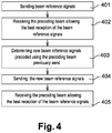
- the figure 4 presents the method of the figure 3 from the point of view of the base station. This method comprises the following iterative steps:
- An embodiment of the present subject matter is a base station.
- This base stations contains different modules configured to realize the method of the figure 4 .
- This base station comprises receiving means and transmission means.
- the receiving means are configured:
- the different modules will be realized by one or more processors and one or more memory.
- the module may also be realized by the use of dedicated hardware as well as hardware capable of executing software in association with appropriate software.
- the modules When provided by a processor, the modules may be provided by a single dedicated processor, by a single shared processor, or by a plurality of individual processors, some of which may be shared.
- explicit use of the term "processor” should not be construed to refer exclusively to hardware capable of executing software, and may implicitly include, without limitation, digital signal processor (DSP) hardware, network processor, application specific integrated circuit (ASIC), field programmable gate array (FPGA), read only memory (ROM) for storing software, random access memory (RAM), and non-volatile storage.
- DSP digital signal processor
- ASIC application specific integrated circuit
- FPGA field programmable gate array
- ROM read only memory
- RAM random access memory
- non-volatile storage Other hardware, conventional and/or custom, may also be included.
- the memory may include any computer-readable medium known in the art including, for example, volatile memory, such as static random access memory (SRAM) and dynamic random access memory (DRAM), and/or non-volatile memory, such as read only memory (ROM), erasable programmable ROM, flash memories, hard disks, optical disks, and magnetic tapes.
- volatile memory such as static random access memory (SRAM) and dynamic random access memory (DRAM)
- non-volatile memory such as read only memory (ROM), erasable programmable ROM, flash memories, hard disks, optical disks, and magnetic tapes.
- the memory includes modules and data.
- the modules include routines, programs, objects, components, data structures, etc., which perform particular tasks or implement particular abstract data types.
- the data serves as a repository for storing data processed, received, and generated by one or more of the modules.
- program storage devices for example, digital data storage media, which are machine or computer readable and encode machine-executable or computer-executable programs of instructions, where said instructions perform some or all of the steps of the described method.
- the program storage devices may be, for example, digital memories, magnetic storage media, such as a magnetic disks and magnetic tapes, hard drives, or optically readable digital data storage media.
- An embodiment of the subject matter is a computer-readable medium having embodied thereon a computer program configured to realize the method, presented figure 1 , to select a precoding beam among a set of possible precoding beams.
- This method comprises an initial step 101 of selecting one of the possible beamwidths. After that the method comprises the following iterative steps:
Landscapes
- Engineering & Computer Science (AREA)
- Computer Networks & Wireless Communication (AREA)
- Signal Processing (AREA)
- Mobile Radio Communication Systems (AREA)
Abstract
Description
- The present subject matter relates to a method to select a precoding beam among a set of possible precoding beams. This precoding beam can for example be used to exchange data between a base station and a user equipment.
- In order to combat path loss, and to maximize spectral efficiency, directional beamforming/precoding solutions are commonly used.
- It is straightforward to state that the optimal beam pattern per user, is to be updated as the user moves and changes its location: spatial characteristics of the channel paths between the base station and the user, are modified. The beam tracking feature intends at switching the best precoding beam according the displacement of the user.
- However, the higher the user's mobility or the evolution of the radio electrical environment of the user, the higher the rate of beam switching to guarantee steady beamforming gain. At the same time the risk for the user to move out of its beam coverage area is increasing and so the risk of connexion dropping.
- The problem is critical for 5G massive MIMO beamforming in millimeters waves systems, due to narrow beamwidth and uncertainty in beam steering due to analog impairments in the radio frequency chain for example the phase noise.
- The problem that is addressed is to design a precoding solution that suits to mobile use cases, by preventing call dropping, guaranteeing continuous coverage, taking into account the user mobility information, especially the speed.
- The present subject matter also allows the stabilization of the beam tracking procedure, by reducing the beam switching rate, to decrease the beam misalignment probability, to reduce the overhead due to beam refinement protocol to save time and radio resources elements used for transmitting refined beam reference signals, while increasing the beamforming gain, through minimal beamwidth.
- This summary is provided to introduce concepts related to methods dedicated to select a precoding beam among a set of possible precoding beams.
- In one implementation a method to select a precoding beam among a set of possible precoding beams is described. This selected precoding beam is use to exchange data between a base station and a user equipment. The possible precoding beams are grouped according to their beamwidth out of a set of possible beamwidths. The method comprises an initial step of selecting one of the possible beamwidths so called selected beamwidth. The method also comprises the following iterative steps; a step of determining measurements associated to precoding beams having this selected beamwidth and a step of selecting the current precoding beam as the one, among the precoding beams having this selected beamwidth, with the best measurements and a step of updating the measurements associated to the precoding beams having the selected beamwidth. Furthermore and if one of the measurement associated to one of the precoding beams, having the selected beamwidth, is above the measurement associated to the current precoding beam, the method comprises a step of changing the current precoding beam to the one with the measurements above the measurements associated to the former current precoding beam and a step of updating a beam switching rate and when the beam switching rate is above a first threshold a step of increasing the selected beamwidth and when the beam switching rate is below a second threshold a step of decreasing the selected beamwidth.
- In another implementation a computer-readable medium is described. This computer-readable medium has embodied a computer program configured to realize a method to select a precoding beam among a set of possible precoding beams. This selected precoding beam is use to exchange data between a base station and a user equipment. The possible precoding beams are grouped according to their beamwidth out of a set of possible beamwidths. The method comprises an initial step of selecting one of the possible beamwidths so called selected beamwidth. The method also comprises the following iterative steps; a step of determining measurements associated to precoding beams having this selected beamwidth and a step of selecting the current precoding beam as the one, among the precoding beams having this selected beamwidth, with the best measurements and a step of updating the measurements associated to the precoding beams having the selected beamwidth. Furthermore and if one of the measurement associated to one of the precoding beams, having the selected beamwidth, is above the measurement associated to the current precoding beam, the method comprises a step of changing the current precoding beam to the one with the measurements above the measurements associated to the former current precoding beam and a step of updating a beam switching rate and when the beam switching rate is above a first threshold a step of increasing the selected beamwidth and when the beam switching rate is below a second threshold a step of decreasing the selected beamwidth.
- The detailed description is given with reference to the accompanying figures. In the figures, the left-most digit(s) of a reference number identifies the figure in which the reference number first appears. The same numbers are used throughout the figures to reference like features and components. Some embodiments of system and/or methods in accordance with embodiments of the present subject matter are now described, by way of example only, and with reference to the accompanying figures, in which:
-
Figure 1 presents a first embodiment of the method of the present subject matter. -
Figure 2 presents a beam resolution or beamwidth table -
Figure 3 presents a method, from the point of view of the user equipment, to exchange information between a user equipment and a base station in order to select a precoding beam -
Figure 4 presents the method of thefigure 3 , from the point of view of the base station - In the present document, the word "exemplary" is used herein to mean "serving as an example, instance, or illustration." Any embodiment or implementation of the present subject matter described herein as "exemplary" is not necessarily to be construed as preferred or advantageous over other embodiments.
- It should be appreciated by those skilled in the art that any block diagrams herein represent conceptual views of illustrative systems embodying the principles of the present subject matter. Similarly, it will be appreciated that any flow charts, flow diagrams, state transition diagrams, pseudo code, and the like represent various processes which may be substantially represented in computer readable medium and so executed by a computer or processor, whether or not such computer or processor is explicitly shown.
- The aim of the present subject matter is a method to select a precoding beam among a set of possible precoding beams. The different possible precoding beams are grouped according to their beamwidth and generally there are several possible precoding beams for a given beamwidth. The selected precoding beam will be used to exchange data between a base station and a user equipment.
- The
figure 1 describes the method to select the precoding beam. This method comprises aninitial step 101 of selecting one of the possible beamwidths. After that the method comprises the following iterative steps: - a
step 102 of determining measurements associated to precoding beams having this selected beamwidth and - a
step 103 of selecting the current precoding beam as the one, among the precoding beams having this selected beamwidth, with the best measurement and - a
step 104 of updating the measurements associated to the precoding beams having the selected beamwidth and - Furthermore and if one of the measurement associated to one of the precoding beams, having the selected beamwidth, is above the measurement associated to the current precoding beam, the method comprising
- a
step 105 of changing the current precoding beam to the one with the measurements above the measurements associated to the former current precoding beam - a
step 106 of updating a beam switching rate and- when the beam switching rate is above a first threshold a
step 107 of increasing the selected beamwidth - when the beam switching rate is below a second threshold a
step 108 of decreasing the selected beamwidth
- when the beam switching rate is above a first threshold a
- Beamwidth is also known as resolution of the beam.
- In an embodiment the initial 101 step of selecting one of the possible beamwidths is configured to select the largest beamwidth. In an embodiment the base station transmits Beam Reference Signals over beams with largest beamwidth. The user equipement then measures the power that is received over the scanned reference signals and then reports to the base station the beam index and maximum received power to the base station.
- Regarding the first threshold, a too low value will trigger unusually the beamwidth increase process, which degrades the expected beamforming gain. In opposite a too high value will have an impact on beam misalignment.
- Regarding the second threshold a too low value will limit the opportunity of refining the beamwidth, which negatively impacts the beamforming gain. In opposite a too high value increases too 'optimistically' the opportunity of beam refining, which leads to beam misalignment and call drop.
- The optimal values for these two thresholds can be setup experimentally and offline, through Self Configuring solutions. The objective is to maximize the beamforming gain, with the constraint of minimal beamforming misalignment. This tradeoff can be simply captured by maximizing the user throughput.
- An example of implementation for a fine tuning of these thresholds, that is done 'offline', during an experimental phase, can be based on optimization theory methods to find the global optimum of a function to maximize. Different functions to maximize can be considered. The objective is to maximize for all the users, (or x% of these users), the beamforming gain, or the SINR, while minimizing the beam misalignment probability. For example, we can maximize the aggregation of averaged user throughput using the following formula:

- In other embodiment the following formula can be used:

- prob_BeamMisalignment being the probability of beam misalignment. The probability of beam misalignment can be estimated by the ratio: the time during the serving user beam is not appropriate out of the time during which the user beam is the relevant one.
- SINRk being the Signal to Interference and Noise ratio at user k.
- The first and second threshold can be determined using Simulated Annealing (SA) principles. Simulated annealing is a well-known meta heuristic method for solving a complex global optimization problem: maximize (or minimize) a function. The main advantages of using SA compared to other methods is that it can deal with non-linear, non-differentiable problems with local optima. Simulated Annealing is inspired from the annealing process in metallurgy where the metal is heated then cooled before being frozen in the desired state: when the looked-for material properties are met (like hardness, flexibility). The system, via the method described below, is controlled by the temperature T:
- When temperature is high, large bounces (system changes) are allowed.
- When temperature is low, less random movements from one state to another is tolerated.
- The system is then frozen to the stable optimal state.
- To determine the first of second threshold of the method of the present subject matter the following step can be used:
- 1. The algorithm starts with an initial random state: S = (First Threshold, Second Threshold)
- 2. The resulting objective function is calculated: F(S)
- 3. A neighboring random solution is then generated: S' = Neighbour(S)
- 4. The objective function is then re-evaluated on this updated state: neighbor to S: F(S')
- 5. If F(S') > F(S) then update the state: S := S'
If F(S') < F(S) then, update the state with an acceptance probability (even if it outputs a worse objective function, but this is to avoid being stuck in a local optimum):- Accept with probability:

- Reject with probability:

- Note: indeed, at high temperatures, the new state can be accepted even with high Δ variations. At low temperatures, the new state is accepted only when the measured variations: Δ are small.
- Accept with probability:
- 6. Adjust the temperature: for example, T = α.T , with α a constant (the cooling factor) and
Go to step 2. - With the method of the previous section, the temperature is initialized at a fixed value T 0. Experimentations realized offline can help improving this fixed value. This initialization value must be high enough in order to allow each solution determined at the beginning of the method to be accepted with a probability of almost 1. After that this temperature can be up-dated using different solutions. For example using the formula T = α.T wherein α est fixed parameter comprises between 0.8 and 0.99. One other formula can be Tk = T0 .αk wherein k is the temperature cycle, this formula is also known as "Exponential multiplicative cooling".
- In some other implementation/variation of the method of the previous section, the cooling schedule part of the method can interact several times using the same temperature. The
steps 2 and 5 of the method of the section 27 are then realized L times using the same temperature and after that the cooling schedule is used. - In an embodiment the method of section 27 stops when the number of iterations is reached or when F(First Threshold, Second Threshold) > Target, or when the function F(First Threshold, Second Threshold) converges toward a maximal with only small oscillations.
- By measurements we mean power measurement on Reference Signals that are transmitted on different directions, over different beams. These reference signals are Beam Reference Signals (BRS) or Beam Refinement Reference Signals (BRRS), as specified in SIGs for Verizon Wireless and Korean Telecom. The SIG for Verizon Wireless can be obtain in the website http://www.5gtf.org/ and the SIG for Korean Telecom can be obtain in the website https://www.kt.com/eng/biz/kt5g_02.jsp.
- By beam switching rate, we mean the frequency of changing the best serving beam on a given beamwidth for a given user. This is an indication that the considered beamwidth is or is not the relevant one, given current mobility characteristics of the user or the environment. Beam switching rate can be calculated by the ratio of the number best serving beam changes at a given beamwidth to the observation duration.
- In an embodiment if the beam switching rate is comprised between the first and second threshold a step of keeping the same beamwidth is realized.
- In other words the previously described method relies on appropriate beamwidth adaptation, depending on the user/environment mobility profile, captured through beam switching statistics and rate metric. Supposing that multi-resolution precoding is enabled, the BS has the capability to transmit over beams with quantized different beamwidths:
- Large beamwidths (so large beam coverage) are to be assigned to users with high beam switching rate. Purpose is to guarantee stability, avoid beam misalignment, guarantee coverage performances between consecutive beam updating periods, (this is achieved at the expense of data rate),
- Smaller beamwidths are preferred for low / medium beam switching rates users. Purpose is to take profit of higher beamforming gain, higher Multi Users capacity gain, enabled by refined beamwidths.
- Within the next sections of this divulgation the following notations will be used:
- Bb : the current beam, on selected beam iteration b (similarly, beamwidth resolution).
- b : b ∈ {b 0, ..., bN } - See
Figure 2 . -

- Sb ,

- L: Number of beam measurements reported to the Base Station.
- Rb : beam switching rate for the current selected beamwidth b.
- n_swb : Number of switching occurrences.
- Rref, RMax : Reference beam switching rate threshold, Maximum beam switching rate.
- Δ r : Hysteresis like threshold on beam switching rate.
- Δ s : Hysteresis like threshold on beam measurements.
- Step 1: Set b = b 0, perform beam acquisition: select Bb.
- Step 2: UE performs measurements on Bb and


- Step 3: Rank the current and best beams, and update switching statistics, beam selection.
Supposing: beam measurement is Beam RSRP, SNR:


- Step 4: Fallback
If Rb > RMax Go toStep 1 - Step 5: Increase beamwidth
If Rb > Rref + Δr or if Rb > First Threshold- b = b - 1
- Bb and

Step 2
- Step 6: Decrease Beamwidth
If Rb < Rref - Δ r or if Rb < Second Threshold- b = b + 1 (Beam refinement)
- Bb and

Step 2
- The present subject matter also comprises a method to exchange information between a user equipment and a base station in order to select a precoding beam. This method is described
figure 3 and from the point of view of the user equipment comprises the following iterative steps: - A
step 301 of receiving, from the base station, beam reference signals - A
step 302 of performing quality measurements of the reception of these beam reference signals - A
step 303 of determining which precoding beams allow the best reception of the beam reference signals - A
step 304 of sending, to the base station, the precoding beam allowing the best reception of the beam reference signals - A
step 305 of receiving, form the base station, new beam reference signals precoded using the precoding beam previously send - A
step 306 of performing quality measurements of the reception of these new beam reference signals - A
step 307 of determining which precoding beams allow the best reception of the new beam reference signals - A
step 308 of sending, to the base station, the precoding beam allowing the best reception of the new beam reference signals - The iterative process stops when the lowest beamwidth is reached for a beam switching rate that do not exceed a pre-set upper bound.
- An embodiment of the present subject matter is a user equipment. This user contains different modules configured to realize the method of the
figure 3 . This user equipment comprises receiving means and transmission means. The receiving means are configured: - to receive, from the base station, beam reference signals and
- to receive, form the base station, new beam reference signals precoded using the precoding beam previously sent.
- to send, to the base station, the precoding beam allowing the best reception of the beam reference signals and
- to send, to the base station, the precoding beam allowing the best reception of the new beam reference signals.
- to perform quality measurements of the reception of these beam reference signals and
- to determine which precoding beams allow the best reception of the beam reference signals and
- to perform quality measurements of the reception of these new beam reference signals and to determine which precoding beams allow the best reception of the new beam reference signals.
- The different modules will be realized by one or more processors and one or more memory. The module may also be realized by the use of dedicated hardware as well as hardware capable of executing software in association with appropriate software. When provided by a processor, the modules may be provided by a single dedicated processor, by a single shared processor, or by a plurality of individual processors, some of which may be shared. Moreover, explicit use of the term "processor" should not be construed to refer exclusively to hardware capable of executing software, and may implicitly include, without limitation, digital signal processor (DSP) hardware, network processor, application specific integrated circuit (ASIC), field programmable gate array (FPGA), read only memory (ROM) for storing software, random access memory (RAM), and non-volatile storage. Other hardware, conventional and/or custom, may also be included.
- The memory may include any computer-readable medium known in the art including, for example, volatile memory, such as static random access memory (SRAM) and dynamic random access memory (DRAM), and/or non-volatile memory, such as read only memory (ROM), erasable programmable ROM, flash memories, hard disks, optical disks, and magnetic tapes. The memory includes modules and data. The modules include routines, programs, objects, components, data structures, etc., which perform particular tasks or implement particular abstract data types. The data, amongst other things, serves as a repository for storing data processed, received, and generated by one or more of the modules.
- The
figure 4 presents the method of thefigure 3 from the point of view of the base station. This method comprises the following iterative steps: - A
step 401 of sending, to the user equipment, beam reference signals - A
step 402 of receiving, from the user equipment, a precoding beam allowing the best reception of the beam reference signals - A
step 403 of determining new beam reference signals precoded using the precoding beam previously received - A
step 404 of sending, to the user equipment, the new beam reference signals precoded using the precoding beam previously send - A
step 405 of receiving, from the user equipment, a precoding beam allowing the best reception of the new beam reference signals - The iterative process stops when the lowest beamwidth is reached for a beam switching rate that do not exceed a pre-set upper bound.
- An embodiment of the present subject matter is a base station. This base stations contains different modules configured to realize the method of the
figure 4 . This base station comprises receiving means and transmission means. The receiving means are configured: - to receive, from the user equipment, the precoding beam allowing the best reception of the beam reference signals and
- to receive, from the user equipment, the new precoding beam allowing the best reception of the beam reference signals
- to send, to the user equipment, beam reference signals and
- to send, to the user equipment, the new beam reference signals precoded using the precoding beam previously sent
- The different modules will be realized by one or more processors and one or more memory. The module may also be realized by the use of dedicated hardware as well as hardware capable of executing software in association with appropriate software. When provided by a processor, the modules may be provided by a single dedicated processor, by a single shared processor, or by a plurality of individual processors, some of which may be shared. Moreover, explicit use of the term "processor" should not be construed to refer exclusively to hardware capable of executing software, and may implicitly include, without limitation, digital signal processor (DSP) hardware, network processor, application specific integrated circuit (ASIC), field programmable gate array (FPGA), read only memory (ROM) for storing software, random access memory (RAM), and non-volatile storage. Other hardware, conventional and/or custom, may also be included.
- The memory may include any computer-readable medium known in the art including, for example, volatile memory, such as static random access memory (SRAM) and dynamic random access memory (DRAM), and/or non-volatile memory, such as read only memory (ROM), erasable programmable ROM, flash memories, hard disks, optical disks, and magnetic tapes. The memory includes modules and data. The modules include routines, programs, objects, components, data structures, etc., which perform particular tasks or implement particular abstract data types. The data, amongst other things, serves as a repository for storing data processed, received, and generated by one or more of the modules.
- A person skilled in the art will readily recognize that steps of the methods, presented above, can be performed by programmed computers. Herein, some embodiments are also intended to cover program storage devices, for example, digital data storage media, which are machine or computer readable and encode machine-executable or computer-executable programs of instructions, where said instructions perform some or all of the steps of the described method. The program storage devices may be, for example, digital memories, magnetic storage media, such as a magnetic disks and magnetic tapes, hard drives, or optically readable digital data storage media.
- An embodiment of the subject matter is a computer-readable medium having embodied thereon a computer program configured to realize the method, presented
figure 1 , to select a precoding beam among a set of possible precoding beams. This method comprises aninitial step 101 of selecting one of the possible beamwidths. After that the method comprises the following iterative steps: - a
step 102 of determining measurements associated to precoding beams having this selected beamwidth and - a
step 103 of selecting the current precoding beam as the one, among the precoding beams having this selected beamwidth, with the best measurement and - a
step 104 of updating the measurements associated to the precoding beams having the selected beamwidth and - a
step 105 of changing the current precoding beam to the one with the measurements above the measurements associated to the former current precoding beam - a
step 106 of updating a beam switching rate and- when the beam switching rate is above a first threshold a
step 107 of increasing the selected beamwidth. - when the beam switching rate is below a second threshold a
step 108 of decreasing the selected beamwidth.
- when the beam switching rate is above a first threshold a
Claims (10)
- Method to select a precoding beam among a set of possible precoding beams,
this selected precoding beam being use to exchange data between a base station and a user equipment,
the possible precoding beams being grouped according to their beamwidth out of a set of possible beamwidths,
the method comprising an initial step (101) of selecting one of the possible beamwidths so called selected beamwidth and
the following iterative steps:• a step (102) of determining measurements associated to precoding beams having this selected beamwidth and• a step (103) of selecting the current precoding beam as the one, among the precoding beams having this selected beamwidth, with the best measurements and• a step (104) of updating the measurements associated to the precoding beams having the selected beamwidth andFurthermore and if one of the measurement associated to one of the precoding beams, having the selected beamwidth, is above the measurement associated to the current precoding beam, the method comprising• a step (105) of changing the current precoding beam to the one with the measurements above the measurements associated to the former current precoding beam and• a step (106) of updating a beam switching rate and• when the beam switching rate is above a first threshold a step (107) of increasing the selected beamwidth• when the beam switching rate is below a second threshold a step (108) of decreasing the selected beamwidth. - Method according to claim 1 wherein the initial step (101) of selecting one of the possible beamwidths is also configured to select the largest beamwidth.
- Method according to claims 1 or 2 wherein the step (102) of determining measurements associated to precoding beams having this selected beamwidth is also configured to calculate reception power of reference signals transmitted using precoding beams having this selected beamwidth.
- Method according to any of the previous claims wherein after the step (106) of updating a beam switching rate and if the beam switching rate is comprised between the first and second threshold the method also comprises a step of keeping the same beamwidth is realized.
- Method according to any of the previous claims wherein the first threshold and/or second thresholds are determined using optimization theory methods to find the global optimum of a function to maximize.
- Computer-readable medium having embodied thereon a computer program configured to realize a method to select a precoding beam among a set of possible precoding beams,
this selected precoding beam being use to exchange data between a base station and a user equipment,
the possible precoding beams being grouped according to their beamwidth out of a set of possible beamwidths,
the method comprising an initial step (101) of selecting one of the possible beamwidths so called initial b beamwidth and
the following iterative steps:• a step (102) of determining measurements associated to precoding beams having this selected beamwidth and• a step (103) of selecting the current precoding beam as the one, among the precoding beams having this selected beamwidth, with the best measurement and• a step (104) of updating the measurements associated to the precoding beams having the selected beamwidth andFurthermore and if one of the measurement associated to one of the precoding beams, having the selected beamwidth, is above the measurement associated to the current precoding beam, the method comprising• a step (105) of changing the current precoding beam to the one with the measurements above the measurements associated to the former current precoding beam and• a step (106) of updating a beam switching rate and• when the beam switching rate is above a first threshold a step (107) of increasing the selected beamwidth• when the beam switching rate is below a second threshold a step (108) of decreasing the selected beamwidth. - Computer-readable medium according to claim 6 wherein the initial step (101) of selecting one of the possible beamwidths is also configured to select the largest beamwidth.
- Computer-readable medium according to claims 6 or 7 wherein the a step (102) of determining measurements associated to precoding beams having this selected beamwidth is also configured to calculate reception power of reference signals transmitted using precoding beams having this selected beamwidth.
- Computer-readable medium according to any of the claims 6 to 8 wherein after the step (106) of updating a beam switching rate and if the beam switching rate is comprised between the first and second threshold the method also comprises a step of keeping the same beamwidth is realized.
- Computer-readable medium according to any of the claims 6 to 9 wherein the first threshold and/or second thresholds are determined using optimization theory methods to find the global optimum of a function to maximize.
Priority Applications (2)
| Application Number | Priority Date | Filing Date | Title |
|---|---|---|---|
| EP19190205.5A EP3614577A1 (en) | 2017-02-28 | 2017-02-28 | Method and computer-readable medium to select a precoding beam among a set of possible precoding beams |
| EP17158429.5A EP3367588B1 (en) | 2017-02-28 | 2017-02-28 | Method and computer-readable medium to select a precoding beam among a set of possible precoding beams |
Applications Claiming Priority (1)
| Application Number | Priority Date | Filing Date | Title |
|---|---|---|---|
| EP17158429.5A EP3367588B1 (en) | 2017-02-28 | 2017-02-28 | Method and computer-readable medium to select a precoding beam among a set of possible precoding beams |
Related Child Applications (2)
| Application Number | Title | Priority Date | Filing Date |
|---|---|---|---|
| EP19190205.5A Division-Into EP3614577A1 (en) | 2017-02-28 | 2017-02-28 | Method and computer-readable medium to select a precoding beam among a set of possible precoding beams |
| EP19190205.5A Division EP3614577A1 (en) | 2017-02-28 | 2017-02-28 | Method and computer-readable medium to select a precoding beam among a set of possible precoding beams |
Publications (2)
| Publication Number | Publication Date |
|---|---|
| EP3367588A1 true EP3367588A1 (en) | 2018-08-29 |
| EP3367588B1 EP3367588B1 (en) | 2019-09-25 |
Family
ID=58231394
Family Applications (2)
| Application Number | Title | Priority Date | Filing Date |
|---|---|---|---|
| EP17158429.5A Active EP3367588B1 (en) | 2017-02-28 | 2017-02-28 | Method and computer-readable medium to select a precoding beam among a set of possible precoding beams |
| EP19190205.5A Withdrawn EP3614577A1 (en) | 2017-02-28 | 2017-02-28 | Method and computer-readable medium to select a precoding beam among a set of possible precoding beams |
Family Applications After (1)
| Application Number | Title | Priority Date | Filing Date |
|---|---|---|---|
| EP19190205.5A Withdrawn EP3614577A1 (en) | 2017-02-28 | 2017-02-28 | Method and computer-readable medium to select a precoding beam among a set of possible precoding beams |
Country Status (1)
| Country | Link |
|---|---|
| EP (2) | EP3367588B1 (en) |
Cited By (4)
| Publication number | Priority date | Publication date | Assignee | Title |
|---|---|---|---|---|
| WO2020135919A1 (en) * | 2018-12-28 | 2020-07-02 | Nokia Technologies Oy | Selecting beamforming options |
| CN113365280A (en) * | 2020-03-02 | 2021-09-07 | 中兴通讯股份有限公司 | Method and device for optimizing coverage of millimeter wave system, electronic equipment and storage medium |
| CN113853750A (en) * | 2019-05-31 | 2021-12-28 | 高通股份有限公司 | System and method for determining a dynamic beam list |
| CN116193586A (en) * | 2021-11-24 | 2023-05-30 | 大唐移动通信设备有限公司 | Beam adaptive adjustment method, device, base station equipment and storage medium |
Families Citing this family (1)
| Publication number | Priority date | Publication date | Assignee | Title |
|---|---|---|---|---|
| CN113540831B (en) * | 2020-04-17 | 2023-01-13 | 中国移动通信有限公司研究院 | Method for adaptively adjusting beam width and antenna |
-
2017
- 2017-02-28 EP EP17158429.5A patent/EP3367588B1/en active Active
- 2017-02-28 EP EP19190205.5A patent/EP3614577A1/en not_active Withdrawn
Non-Patent Citations (3)
| Title |
|---|
| NOFAL M ET AL: "Performance and feasibility of different switched-BEAM antennas for the stratospheric platform mobile communications covering newly developing regions", RADIO SCIENCE NINETEENTH NATIONAL CONFERENCE OF THE PROCEEDINGS NRSC 2 002 MAR. 19-21, 2002, PISCATAWAY, NJ, USA,IEEE, 19 March 2002 (2002-03-19), pages 133 - 140, XP010596134, ISBN: 978-977-5031-72-3 * |
| NOKIA ALCATEL-LUCENT SHANGHAI BELL: "RRM Requirements supporting NR beam management", vol. RAN WG4, no. Reno, USA; 20161114 - 20161118, 14 November 2016 (2016-11-14), XP051180431, Retrieved from the Internet <URL:http://www.3gpp.org/ftp/Meetings_3GPP_SYNC/RAN4/Docs/> [retrieved on 20161114] * |
| ZTE ET AL: "Group based beam management for NR-MIMO", vol. RAN WG1, no. Athens, Greece; 20170213 - 20170217, 12 February 2017 (2017-02-12), XP051208964, Retrieved from the Internet <URL:http://www.3gpp.org/ftp/Meetings_3GPP_SYNC/RAN1/Docs/> [retrieved on 20170212] * |
Cited By (6)
| Publication number | Priority date | Publication date | Assignee | Title |
|---|---|---|---|---|
| WO2020135919A1 (en) * | 2018-12-28 | 2020-07-02 | Nokia Technologies Oy | Selecting beamforming options |
| CN113853750A (en) * | 2019-05-31 | 2021-12-28 | 高通股份有限公司 | System and method for determining a dynamic beam list |
| CN113853750B (en) * | 2019-05-31 | 2024-02-09 | 高通股份有限公司 | System and method for determining dynamic beam lists |
| US12150106B2 (en) | 2019-05-31 | 2024-11-19 | Qualcomm Incorporated | System and method for determination of a dynamic beam list |
| CN113365280A (en) * | 2020-03-02 | 2021-09-07 | 中兴通讯股份有限公司 | Method and device for optimizing coverage of millimeter wave system, electronic equipment and storage medium |
| CN116193586A (en) * | 2021-11-24 | 2023-05-30 | 大唐移动通信设备有限公司 | Beam adaptive adjustment method, device, base station equipment and storage medium |
Also Published As
| Publication number | Publication date |
|---|---|
| EP3367588B1 (en) | 2019-09-25 |
| EP3614577A1 (en) | 2020-02-26 |
Similar Documents
| Publication | Publication Date | Title |
|---|---|---|
| CN109379752B (en) | Optimization method, apparatus, device and medium for Massive MIMO | |
| US12237889B2 (en) | Wireless device, a radio node, and methods therein | |
| Jiao et al. | Enabling efficient blockage-aware handover in RIS-assisted mmWave cellular networks | |
| EP3776908B1 (en) | Method and apparatus for sensor assisted beam selection, beam tracking, and antenna module selection | |
| Aykin et al. | MAMBA: A multi-armed bandit framework for beam tracking in millimeter-wave systems | |
| EP3367588B1 (en) | Method and computer-readable medium to select a precoding beam among a set of possible precoding beams | |
| JP5248672B2 (en) | Multi-resolution beamforming based on codebook in MIMO system | |
| EP3646479B1 (en) | A first radio node and methods therein for adjusting a set of beams for communication in a wireless communications network | |
| EP3956996B1 (en) | Multi-band beam codebook design and operations | |
| Shen et al. | Design and implementation for deep learning based adjustable beamforming training for millimeter wave communication systems | |
| EP3652870B1 (en) | Frequency-selective beam management | |
| US11546033B2 (en) | Method of performing beam training based on reinforcement learning and wireless communication device performing the same | |
| CN113994600A (en) | Design and adaptation of hierarchical codebooks | |
| EP2930966A1 (en) | Selecting beam-forming weighting vectors for antennae | |
| US8989050B2 (en) | Graph-based distributed coordination methods for wireless communication networks | |
| US12255708B2 (en) | Transmission of MU-MIMO signals | |
| US20200274591A1 (en) | Remote radio head, beamforming method and storage medium | |
| WO2019080999A1 (en) | Beam training of a radio transceiver device | |
| US20180331748A1 (en) | Mobile communication device and method for selecting a beam direction | |
| US20250023618A1 (en) | Interference suppression in a wireless communication network | |
| CN101321008A (en) | Downlink beamforming transmission method and device | |
| CN119678392A (en) | Method and apparatus for complex beam operation in a wireless communication system | |
| CN115085751A (en) | Wireless communication device including antenna module and method of operating wireless communication device | |
| Ly et al. | Initial access optimization for millimeter wave wireless networks | |
| US12316407B2 (en) | Method for adaptive beam sweeping |
Legal Events
| Date | Code | Title | Description |
|---|---|---|---|
| PUAI | Public reference made under article 153(3) epc to a published international application that has entered the european phase |
Free format text: ORIGINAL CODE: 0009012 |
|
| STAA | Information on the status of an ep patent application or granted ep patent |
Free format text: STATUS: THE APPLICATION HAS BEEN PUBLISHED |
|
| AK | Designated contracting states |
Kind code of ref document: A1 Designated state(s): AL AT BE BG CH CY CZ DE DK EE ES FI FR GB GR HR HU IE IS IT LI LT LU LV MC MK MT NL NO PL PT RO RS SE SI SK SM TR |
|
| AX | Request for extension of the european patent |
Extension state: BA ME |
|
| STAA | Information on the status of an ep patent application or granted ep patent |
Free format text: STATUS: REQUEST FOR EXAMINATION WAS MADE |
|
| 17P | Request for examination filed |
Effective date: 20190228 |
|
| GRAP | Despatch of communication of intention to grant a patent |
Free format text: ORIGINAL CODE: EPIDOSNIGR1 |
|
| RBV | Designated contracting states (corrected) |
Designated state(s): AL AT BE BG CH CY CZ DE DK EE ES FI FR GB GR HR HU IE IS IT LI LT LU LV MC MK MT NL NO PL PT RO RS SE SI SK SM TR |
|
| STAA | Information on the status of an ep patent application or granted ep patent |
Free format text: STATUS: GRANT OF PATENT IS INTENDED |
|
| RIC1 | Information provided on ipc code assigned before grant |
Ipc: H04B 7/06 20060101AFI20190320BHEP |
|
| INTG | Intention to grant announced |
Effective date: 20190411 |
|
| GRAS | Grant fee paid |
Free format text: ORIGINAL CODE: EPIDOSNIGR3 |
|
| GRAA | (expected) grant |
Free format text: ORIGINAL CODE: 0009210 |
|
| STAA | Information on the status of an ep patent application or granted ep patent |
Free format text: STATUS: THE PATENT HAS BEEN GRANTED |
|
| RAP1 | Party data changed (applicant data changed or rights of an application transferred) |
Owner name: NOKIA SOLUTIONS AND NETWORKS OY |
|
| AK | Designated contracting states |
Kind code of ref document: B1 Designated state(s): AL AT BE BG CH CY CZ DE DK EE ES FI FR GB GR HR HU IE IS IT LI LT LU LV MC MK MT NL NO PL PT RO RS SE SI SK SM TR |
|
| REG | Reference to a national code |
Ref country code: GB Ref legal event code: FG4D |
|
| REG | Reference to a national code |
Ref country code: CH Ref legal event code: EP |
|
| REG | Reference to a national code |
Ref country code: DE Ref legal event code: R096 Ref document number: 602017007233 Country of ref document: DE |
|
| REG | Reference to a national code |
Ref country code: AT Ref legal event code: REF Ref document number: 1184824 Country of ref document: AT Kind code of ref document: T Effective date: 20191015 |
|
| REG | Reference to a national code |
Ref country code: IE Ref legal event code: FG4D |
|
| REG | Reference to a national code |
Ref country code: NL Ref legal event code: MP Effective date: 20190925 |
|
| PG25 | Lapsed in a contracting state [announced via postgrant information from national office to epo] |
Ref country code: LT Free format text: LAPSE BECAUSE OF FAILURE TO SUBMIT A TRANSLATION OF THE DESCRIPTION OR TO PAY THE FEE WITHIN THE PRESCRIBED TIME-LIMIT Effective date: 20190925 Ref country code: HR Free format text: LAPSE BECAUSE OF FAILURE TO SUBMIT A TRANSLATION OF THE DESCRIPTION OR TO PAY THE FEE WITHIN THE PRESCRIBED TIME-LIMIT Effective date: 20190925 Ref country code: SE Free format text: LAPSE BECAUSE OF FAILURE TO SUBMIT A TRANSLATION OF THE DESCRIPTION OR TO PAY THE FEE WITHIN THE PRESCRIBED TIME-LIMIT Effective date: 20190925 Ref country code: FI Free format text: LAPSE BECAUSE OF FAILURE TO SUBMIT A TRANSLATION OF THE DESCRIPTION OR TO PAY THE FEE WITHIN THE PRESCRIBED TIME-LIMIT Effective date: 20190925 Ref country code: NO Free format text: LAPSE BECAUSE OF FAILURE TO SUBMIT A TRANSLATION OF THE DESCRIPTION OR TO PAY THE FEE WITHIN THE PRESCRIBED TIME-LIMIT Effective date: 20191225 Ref country code: BG Free format text: LAPSE BECAUSE OF FAILURE TO SUBMIT A TRANSLATION OF THE DESCRIPTION OR TO PAY THE FEE WITHIN THE PRESCRIBED TIME-LIMIT Effective date: 20191225 |
|
| REG | Reference to a national code |
Ref country code: LT Ref legal event code: MG4D |
|
| PG25 | Lapsed in a contracting state [announced via postgrant information from national office to epo] |
Ref country code: RS Free format text: LAPSE BECAUSE OF FAILURE TO SUBMIT A TRANSLATION OF THE DESCRIPTION OR TO PAY THE FEE WITHIN THE PRESCRIBED TIME-LIMIT Effective date: 20190925 Ref country code: LV Free format text: LAPSE BECAUSE OF FAILURE TO SUBMIT A TRANSLATION OF THE DESCRIPTION OR TO PAY THE FEE WITHIN THE PRESCRIBED TIME-LIMIT Effective date: 20190925 Ref country code: GR Free format text: LAPSE BECAUSE OF FAILURE TO SUBMIT A TRANSLATION OF THE DESCRIPTION OR TO PAY THE FEE WITHIN THE PRESCRIBED TIME-LIMIT Effective date: 20191226 |
|
| REG | Reference to a national code |
Ref country code: AT Ref legal event code: MK05 Ref document number: 1184824 Country of ref document: AT Kind code of ref document: T Effective date: 20190925 |
|
| PG25 | Lapsed in a contracting state [announced via postgrant information from national office to epo] |
Ref country code: NL Free format text: LAPSE BECAUSE OF FAILURE TO SUBMIT A TRANSLATION OF THE DESCRIPTION OR TO PAY THE FEE WITHIN THE PRESCRIBED TIME-LIMIT Effective date: 20190925 Ref country code: PL Free format text: LAPSE BECAUSE OF FAILURE TO SUBMIT A TRANSLATION OF THE DESCRIPTION OR TO PAY THE FEE WITHIN THE PRESCRIBED TIME-LIMIT Effective date: 20190925 Ref country code: EE Free format text: LAPSE BECAUSE OF FAILURE TO SUBMIT A TRANSLATION OF THE DESCRIPTION OR TO PAY THE FEE WITHIN THE PRESCRIBED TIME-LIMIT Effective date: 20190925 Ref country code: AT Free format text: LAPSE BECAUSE OF FAILURE TO SUBMIT A TRANSLATION OF THE DESCRIPTION OR TO PAY THE FEE WITHIN THE PRESCRIBED TIME-LIMIT Effective date: 20190925 Ref country code: ES Free format text: LAPSE BECAUSE OF FAILURE TO SUBMIT A TRANSLATION OF THE DESCRIPTION OR TO PAY THE FEE WITHIN THE PRESCRIBED TIME-LIMIT Effective date: 20190925 Ref country code: PT Free format text: LAPSE BECAUSE OF FAILURE TO SUBMIT A TRANSLATION OF THE DESCRIPTION OR TO PAY THE FEE WITHIN THE PRESCRIBED TIME-LIMIT Effective date: 20200127 Ref country code: RO Free format text: LAPSE BECAUSE OF FAILURE TO SUBMIT A TRANSLATION OF THE DESCRIPTION OR TO PAY THE FEE WITHIN THE PRESCRIBED TIME-LIMIT Effective date: 20190925 Ref country code: AL Free format text: LAPSE BECAUSE OF FAILURE TO SUBMIT A TRANSLATION OF THE DESCRIPTION OR TO PAY THE FEE WITHIN THE PRESCRIBED TIME-LIMIT Effective date: 20190925 Ref country code: IT Free format text: LAPSE BECAUSE OF FAILURE TO SUBMIT A TRANSLATION OF THE DESCRIPTION OR TO PAY THE FEE WITHIN THE PRESCRIBED TIME-LIMIT Effective date: 20190925 |
|
| PG25 | Lapsed in a contracting state [announced via postgrant information from national office to epo] |
Ref country code: SM Free format text: LAPSE BECAUSE OF FAILURE TO SUBMIT A TRANSLATION OF THE DESCRIPTION OR TO PAY THE FEE WITHIN THE PRESCRIBED TIME-LIMIT Effective date: 20190925 Ref country code: CZ Free format text: LAPSE BECAUSE OF FAILURE TO SUBMIT A TRANSLATION OF THE DESCRIPTION OR TO PAY THE FEE WITHIN THE PRESCRIBED TIME-LIMIT Effective date: 20190925 Ref country code: SK Free format text: LAPSE BECAUSE OF FAILURE TO SUBMIT A TRANSLATION OF THE DESCRIPTION OR TO PAY THE FEE WITHIN THE PRESCRIBED TIME-LIMIT Effective date: 20190925 Ref country code: IS Free format text: LAPSE BECAUSE OF FAILURE TO SUBMIT A TRANSLATION OF THE DESCRIPTION OR TO PAY THE FEE WITHIN THE PRESCRIBED TIME-LIMIT Effective date: 20200224 |
|
| REG | Reference to a national code |
Ref country code: DE Ref legal event code: R097 Ref document number: 602017007233 Country of ref document: DE |
|
| PG2D | Information on lapse in contracting state deleted |
Ref country code: IS |
|
| PG25 | Lapsed in a contracting state [announced via postgrant information from national office to epo] |
Ref country code: DK Free format text: LAPSE BECAUSE OF FAILURE TO SUBMIT A TRANSLATION OF THE DESCRIPTION OR TO PAY THE FEE WITHIN THE PRESCRIBED TIME-LIMIT Effective date: 20190925 Ref country code: IS Free format text: LAPSE BECAUSE OF FAILURE TO SUBMIT A TRANSLATION OF THE DESCRIPTION OR TO PAY THE FEE WITHIN THE PRESCRIBED TIME-LIMIT Effective date: 20200126 |
|
| PLBE | No opposition filed within time limit |
Free format text: ORIGINAL CODE: 0009261 |
|
| STAA | Information on the status of an ep patent application or granted ep patent |
Free format text: STATUS: NO OPPOSITION FILED WITHIN TIME LIMIT |
|
| 26N | No opposition filed |
Effective date: 20200626 |
|
| REG | Reference to a national code |
Ref country code: CH Ref legal event code: PL |
|
| REG | Reference to a national code |
Ref country code: BE Ref legal event code: MM Effective date: 20200229 |
|
| PG25 | Lapsed in a contracting state [announced via postgrant information from national office to epo] |
Ref country code: MC Free format text: LAPSE BECAUSE OF FAILURE TO SUBMIT A TRANSLATION OF THE DESCRIPTION OR TO PAY THE FEE WITHIN THE PRESCRIBED TIME-LIMIT Effective date: 20190925 Ref country code: LU Free format text: LAPSE BECAUSE OF NON-PAYMENT OF DUE FEES Effective date: 20200228 |
|
| PG25 | Lapsed in a contracting state [announced via postgrant information from national office to epo] |
Ref country code: SI Free format text: LAPSE BECAUSE OF FAILURE TO SUBMIT A TRANSLATION OF THE DESCRIPTION OR TO PAY THE FEE WITHIN THE PRESCRIBED TIME-LIMIT Effective date: 20190925 Ref country code: LI Free format text: LAPSE BECAUSE OF NON-PAYMENT OF DUE FEES Effective date: 20200229 Ref country code: CH Free format text: LAPSE BECAUSE OF NON-PAYMENT OF DUE FEES Effective date: 20200229 |
|
| PG25 | Lapsed in a contracting state [announced via postgrant information from national office to epo] |
Ref country code: FR Free format text: LAPSE BECAUSE OF NON-PAYMENT OF DUE FEES Effective date: 20200229 Ref country code: IE Free format text: LAPSE BECAUSE OF NON-PAYMENT OF DUE FEES Effective date: 20200228 |
|
| PG25 | Lapsed in a contracting state [announced via postgrant information from national office to epo] |
Ref country code: BE Free format text: LAPSE BECAUSE OF NON-PAYMENT OF DUE FEES Effective date: 20200229 |
|
| GBPC | Gb: european patent ceased through non-payment of renewal fee |
Effective date: 20210228 |
|
| PG25 | Lapsed in a contracting state [announced via postgrant information from national office to epo] |
Ref country code: GB Free format text: LAPSE BECAUSE OF NON-PAYMENT OF DUE FEES Effective date: 20210228 |
|
| PG25 | Lapsed in a contracting state [announced via postgrant information from national office to epo] |
Ref country code: TR Free format text: LAPSE BECAUSE OF FAILURE TO SUBMIT A TRANSLATION OF THE DESCRIPTION OR TO PAY THE FEE WITHIN THE PRESCRIBED TIME-LIMIT Effective date: 20190925 Ref country code: MT Free format text: LAPSE BECAUSE OF FAILURE TO SUBMIT A TRANSLATION OF THE DESCRIPTION OR TO PAY THE FEE WITHIN THE PRESCRIBED TIME-LIMIT Effective date: 20190925 Ref country code: CY Free format text: LAPSE BECAUSE OF FAILURE TO SUBMIT A TRANSLATION OF THE DESCRIPTION OR TO PAY THE FEE WITHIN THE PRESCRIBED TIME-LIMIT Effective date: 20190925 |
|
| PG25 | Lapsed in a contracting state [announced via postgrant information from national office to epo] |
Ref country code: MK Free format text: LAPSE BECAUSE OF FAILURE TO SUBMIT A TRANSLATION OF THE DESCRIPTION OR TO PAY THE FEE WITHIN THE PRESCRIBED TIME-LIMIT Effective date: 20190925 |
|
| PGFP | Annual fee paid to national office [announced via postgrant information from national office to epo] |
Ref country code: DE Payment date: 20260102 Year of fee payment: 10 |