EP3367556A1 - Device and procedure for testing a power module comprising a multichannel power converter and a synchronous multiphase and multichannel electrical machine - Google Patents
Device and procedure for testing a power module comprising a multichannel power converter and a synchronous multiphase and multichannel electrical machine Download PDFInfo
- Publication number
- EP3367556A1 EP3367556A1 EP18156058.2A EP18156058A EP3367556A1 EP 3367556 A1 EP3367556 A1 EP 3367556A1 EP 18156058 A EP18156058 A EP 18156058A EP 3367556 A1 EP3367556 A1 EP 3367556A1
- Authority
- EP
- European Patent Office
- Prior art keywords
- multichannel
- phases
- electrical machine
- power
- power converter
- Prior art date
- Legal status (The legal status is an assumption and is not a legal conclusion. Google has not performed a legal analysis and makes no representation as to the accuracy of the status listed.)
- Withdrawn
Links
- 238000012360 testing method Methods 0.000 title claims abstract description 31
- 230000001360 synchronised effect Effects 0.000 title claims abstract description 25
- 238000000034 method Methods 0.000 title claims description 12
- 238000010998 test method Methods 0.000 claims description 13
- 230000008878 coupling Effects 0.000 claims description 6
- 238000010168 coupling process Methods 0.000 claims description 6
- 238000005859 coupling reaction Methods 0.000 claims description 6
- 238000006243 chemical reaction Methods 0.000 claims description 4
- 239000003990 capacitor Substances 0.000 description 7
- 230000002441 reversible effect Effects 0.000 description 6
- 238000001914 filtration Methods 0.000 description 3
- 238000010586 diagram Methods 0.000 description 2
- 230000004907 flux Effects 0.000 description 2
- 238000010561 standard procedure Methods 0.000 description 2
- 230000015572 biosynthetic process Effects 0.000 description 1
- 230000007423 decrease Effects 0.000 description 1
- 238000003745 diagnosis Methods 0.000 description 1
- 238000011990 functional testing Methods 0.000 description 1
- 230000010354 integration Effects 0.000 description 1
- 238000004519 manufacturing process Methods 0.000 description 1
- 238000010248 power generation Methods 0.000 description 1
Images

Classifications
-
- G—PHYSICS
- G01—MEASURING; TESTING
- G01R—MEASURING ELECTRIC VARIABLES; MEASURING MAGNETIC VARIABLES
- G01R31/00—Arrangements for testing electric properties; Arrangements for locating electric faults; Arrangements for electrical testing characterised by what is being tested not provided for elsewhere
- G01R31/34—Testing dynamo-electric machines
- G01R31/343—Testing dynamo-electric machines in operation
-
- G—PHYSICS
- G01—MEASURING; TESTING
- G01R—MEASURING ELECTRIC VARIABLES; MEASURING MAGNETIC VARIABLES
- G01R31/00—Arrangements for testing electric properties; Arrangements for locating electric faults; Arrangements for electrical testing characterised by what is being tested not provided for elsewhere
- G01R31/34—Testing dynamo-electric machines
-
- G—PHYSICS
- G01—MEASURING; TESTING
- G01R—MEASURING ELECTRIC VARIABLES; MEASURING MAGNETIC VARIABLES
- G01R31/00—Arrangements for testing electric properties; Arrangements for locating electric faults; Arrangements for electrical testing characterised by what is being tested not provided for elsewhere
- G01R31/28—Testing of electronic circuits, e.g. by signal tracer
- G01R31/2851—Testing of integrated circuits [IC]
-
- G—PHYSICS
- G01—MEASURING; TESTING
- G01R—MEASURING ELECTRIC VARIABLES; MEASURING MAGNETIC VARIABLES
- G01R31/00—Arrangements for testing electric properties; Arrangements for locating electric faults; Arrangements for electrical testing characterised by what is being tested not provided for elsewhere
- G01R31/40—Testing power supplies
- G01R31/42—AC power supplies
-
- H—ELECTRICITY
- H02—GENERATION; CONVERSION OR DISTRIBUTION OF ELECTRIC POWER
- H02P—CONTROL OR REGULATION OF ELECTRIC MOTORS, ELECTRIC GENERATORS OR DYNAMO-ELECTRIC CONVERTERS; CONTROLLING TRANSFORMERS, REACTORS OR CHOKE COILS
- H02P9/00—Arrangements for controlling electric generators for the purpose of obtaining a desired output
- H02P9/02—Details of the control
Definitions
- the invention relates to a device and a procedure for testing an electrical power module, and more particularly a procedure for testing a synchronous multiphase and multichannel electrical machine and its associated multichannel power converter.
- the manufacturer Before delivering an electrical power module to a customer, the manufacturer aims to verify the correct operation of the module.
- This module comprises a power converter and an electrical machine powered by said power converter.
- the manufacturer aims to verify the electrical and mechanical characteristics of the module. It also aims to verify the operation of the control and acquisition chains comprising sensors, interfacing modules, and actuators. It aims to optimize the costs of the testing operations, and to reduce the investments related to the manufacturing of the test bench.
- the power module customer also wishes to test the power module.
- test bench The usual procedure for testing an electrical power module includes a test bench specific to the tests conducted, known as a "back-to-back test bench". This test procedure requires that the assembly being tested, comprising the electrical machine and its associated power converter, be mounted on the test bench.
- the test bench is a large and very heavy device. For example, a test bench for of a generator suitable for a wind turbine weighs around 140 tons.
- Figure 1 shows a back-to-back test bench specific to these tests, as known from the standard technique.
- the test bench comprises two electrical power modules 1 and 2.
- a first electrical power module 1 comprises a power converter 3 which supplies an electrical machine 4 operating in motor mode.
- the shaft of the motor 5 of this first electrical power module is mechanically connected to the shaft of the second power module 2.
- the second power module 2, which is the object of the test procedure, comprises an electrical machine 6 associated with a power converter 7.
- the second power module 2 operates in generator mode.
- the first power module 1 is supplied by a three-phase electrical network R. It drives the second power module 2 connected to a three-phase network R'.
- the electrical and mechanical characteristics of the second power module recorded during the test procedure are analyzed, and allow it to be concluded whether the tested power module 2 conforms or not.
- a second test is performed on the integration line of the module in its environment before shipping, such as in the case of a wind turbine, when the power module is mounted in the nacelle of the wind turbine. This is a functional test.
- the power module is supplied by an external source. It is checked that the axle of the electrical machine starts to move.
- the module being tested must be mounted on a test bench, which implies that the assembly cannot be tested in its working environment, and customers that are not equipped with such a test bench cannot test their power module easily.
- the power module in the case of a power module operating in generator mode and equipping an offshore wind turbine, the power module cannot be tested when it is integrated into the nacelle of the wind turbine and connected to all of the auxiliary components.
- the interfaces connecting the power unit to the other components cannot be tested either.
- test procedure performed prior to shipping the module is brief. It involves ensuring that the powertrain is able to drive the shaft of the electrical machine. No diagnosis can be made regarding the quality of the devices comprising the power module, such as the sensors included in the nacelle which perform the acquisition of the characteristics of the electrical machine.
- the objective of the invention is therefore to eliminate these disadvantages.
- the invention proposes a device for testing a power module comprising a multichannel power converter and a synchronous multiphase and multichannel electrical machine intended to be supplied by the converter, whereby the synchronous multiphase and multichannel electrical machine has phases connected to one another by groups of three phases.
- the power converter comprises as many voltage inverters as there are groups of three phases connected to said converter, whereby each inverter is connected to a group of three phases.
- Another characteristic of the invention is that the three phases of a group are connected in a star or delta configuration or by any other coupling.
- the stator of the synchronous multiphase and multichannel electrical machine comprises a plurality of groups of three phases with a magnetic coupling level to make it possible to control each channel separately.
- the synchronous multiphase and multichannel electrical machine operates in motor or generator mode.
- Another characteristic of the device is that the shaft of the synchronous multiphase and multichannel electrical machine is free.
- the invention also relates to a procedure for testing a power module comprising a multichannel power converter and a synchronous multiphase and multichannel electrical machine intended to be supplied by the converter, whereby the synchronous multiphase and multichannel electrical machine comprises a stator comprising phases connected to one another by groups of three phases, the groups of phases are magnetically decoupled from each other and are each connected to the multichannel power converter, and a transformer connected to a three-phase electrical network supplies the multichannel power converter.
- Another characteristic of the procedure according to the invention is that it comprises at least one step whereby a group of three phases drives the rotor of the electrical machine at a predetermined rotational speed, and one or more other groups of three phases that form the object of the test procedure operate in generator mode and apply electromagnetic torque to the rotor of the synchronous multiphase and multichannel electrical machine.
- the three phases of a group are connected in a star or delta configuration or by any other coupling.
- the transformer supplies the multichannel power converter with a power value equal to the value of the power lost during the various energy conversion steps.
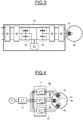
- Fig. 2 shows an electrical power diagram of an electrical power module comprising a multiphase and multichannel electrical machine and a multichannel power converter.
- the power module is intended to be integrated into the nacelle of a wind turbine.
- the power circuit of the power module comprises a multichannel three-phase power converter 11 and a synchronous multiphase and multichannel electrical machine 10 supplied by the converter.
- the same-phase inputs of the power converter 11 are connected to one another and to the corresponding output of a three-phase transformer 12.
- the transformer 12 is supplied by a three-phase electrical network R.
- the entire device comprising the power converter 11 and the multiphase and multichannel electrical machine 10 is controlled by a control device (not shown).
- the synchronous multiphase and multichannel electrical machine 10 comprises a stator and a rotor.
- the stator includes a plurality of phases that are multiples of three.
- the phases are connected to one another by groups of three phases.
- the three phases of a group are connected in a star configuration.
- the stars have a strong magnetic decoupling between them. As a result, the magnetic fluxes generated by one star do not disturb another star. The magnetic decoupling level allows each channel to be controlled separately.
- the machine 10 comprises, for example, nine phases grouped into three groups of triple phases 13, 14, 15 connected in a star configuration.
- the power converter 11 has a plurality of identically formed channels.
- Each output of a channel is connected to a group of triple phases in the star configuration of the electrical machine 10. Therefore, the number of channels of the power converter 11 is equal to the number of triple-phase groups in the star configuration of the machine 10.
- the inputs of the same-phase channels are connected to one another and to the corresponding output of the transformer 12.
- the electrical machine comprises three groups of triple phases in a star configuration 13, 14 and 15. Therefore, the power converter 11 comprises three channels 16, 17, 18.
- Fig. 3 shows the formation of the channel 16 of the multichannel power converter 11. All channels are formed identically.
- Channel 16 comprises a harmonic filtering device 20 whose inputs are intended to be connected to the transformer 12 and to the other channel inputs of the power converter 11.
- the outputs of the filter 20 are connected to the inputs of a controlled and reversible bridge rectifier 21.
- the outputs of the bridge rectifier 21 are connected to a capacitor bank 22.
- the DC voltage filtering assembly 22 comprises two groups of series-connected capacitors whose ends are connected to the rectifier bridge 21, to a brake chopper 23 and to the inputs of a reversible voltage inverter 25, and whose midpoint between the two capacitors is connected to the brake chopper.
- a second capacitor bank 24 formed identically to capacitor bank 22 is connected to the inputs of the reversible voltage inverter 25.
- the midpoint between the two capacitors of the capacitor bank 24 is connected to the reversible voltage inverter 25.
- the outputs of the voltage inverter 25 are connected to a dV/dT filter 26.
- the outputs of the filter 26 are connected to a group of triple phases in the star configuration of the electrical machine 10.
- the filtering device 20 the controlled and reversible bridge rectifier 21, the brake chopper 23, the reversible voltage inverter 25 and the dV/dT filter 26 are not discussed in detail here, since these elements are known to skilled technicians.
- Fig. 4 shows the power exchange fluxes during the test procedure of a star assembly and an associated voltage inverter. The test procedure is repeated for each group of triple phases or for a plurality of groups of triple phases in the star configuration of the electrical machine 10 and the associated channel(s) of the power converter 11 being tested.
- test procedure is shown, for example, in the assembly 27, which comprises the triple-phase group in a star configuration 15 and the channel 18 of the power converter 11.
- the rotor of the electrical machine 10 is set in motion by the assembly 28, which comprises the triple-phase groups in a star configuration 13 and 14 supplied by the channels 16 and 17 of the power converter 11.
- the assembly 27 is initially supplied by the transformer 12.
- the triple-phase groups in a star configuration 13 and 14 are called motor groups.
- the number of triple-phase motor groups in a star configuration is chosen such that the total rated power output delivered by the stars is at least equal to the rated power of the tested assembly.
- the electrical machine 10 is controlled in terms of its speed.
- the assembly 27 being tested is controlled such that it operates in power generation mode.
- connection speed corresponds to the rotational speed from which the electrical machine and the power converter assembly would produce sufficient power to supply an electrical network if they were operating in generator mode.
- the connection speed is 3.7 rpm.
- the assembly 27 controls the electrical machine 10 in terms of its torque.
- the electrical power P gen generated by the assembly 27 is transferred to the motor assembly 28.
- the motor powers P mot1 and P mot2 consumed by the assembly 27 are equal to the sum of the power P gen and the power lost during the various energy conversion steps P loss .
- the transformer 12 compensates for the losses generated by the electrical machine 10 and the power converter 11.
- the electrical network R now only provides the power lost during the energy conversion steps P loss .
- the dimensions of the transformer are reduced, for example for an electrical machine 10 with a rated power of 6 MW, i.e. a power of 2 MW per group of triple phases in a star configuration, if two groups of triple phases in a star configuration are motor groups.
- a transformer with a power of a few dozen KW is therefore sufficient to conduct the test procedure.
- the resistive electromagnetic torque generated by the assembly 27 comprising a group of triple phases in a star configuration 15 and the channel 18 of the associated power converter 11 applied to the rotor of the electrical machine 10 is increased gradually. As a result, the rotational speed of the rotor decreases.
- the control system increases the motor power delivered by the assembly 28 until the rotational speed setpoint is reached.
- the resistive torque can thus be increased until the power generated by the resistive torque is equal to the motor power generated by the assembly 28.
- the power generated by the assembly 27 is compared to the expected values in order to validate the operation of the assembly 27.
- test procedure has the advantage of testing the power module over its entire range of use by using the acquisition, control and power chains of the module in its environment, such as in the case of a wind turbine, when the power module is mounted in the nacelle of the wind turbine.
- the test device has an architecture that makes it possible to perform power exchanges within the power module without a mechanical interface 5 with another test module in rotation.
- the power modules 11 can thus be tested functionally (in terms of their control and power) prior to shipping the machine 10.
Landscapes
- Engineering & Computer Science (AREA)
- Physics & Mathematics (AREA)
- General Physics & Mathematics (AREA)
- Power Engineering (AREA)
- Computer Hardware Design (AREA)
- Microelectronics & Electronic Packaging (AREA)
- General Engineering & Computer Science (AREA)
- Control Of Eletrric Generators (AREA)
Abstract
Description
- The invention relates to a device and a procedure for testing an electrical power module, and more particularly a procedure for testing a synchronous multiphase and multichannel electrical machine and its associated multichannel power converter.
- Before delivering an electrical power module to a customer, the manufacturer aims to verify the correct operation of the module. This module comprises a power converter and an electrical machine powered by said power converter. The manufacturer aims to verify the electrical and mechanical characteristics of the module. It also aims to verify the operation of the control and acquisition chains comprising sensors, interfacing modules, and actuators. It aims to optimize the costs of the testing operations, and to reduce the investments related to the manufacturing of the test bench.
- In addition, the power module customer also wishes to test the power module.
- The usual procedure for testing an electrical power module includes a test bench specific to the tests conducted, known as a "back-to-back test bench". This test procedure requires that the assembly being tested, comprising the electrical machine and its associated power converter, be mounted on the test bench. The test bench is a large and very heavy device. For example, a test bench for of a generator suitable for a wind turbine weighs around 140 tons.
Figure 1 shows a back-to-back test bench specific to these tests, as known from the standard technique. - The test bench comprises two
electrical power modules 1 and 2. A first electrical power module 1 comprises a power converter 3 which supplies anelectrical machine 4 operating in motor mode. The shaft of themotor 5 of this first electrical power module is mechanically connected to the shaft of thesecond power module 2. Thesecond power module 2, which is the object of the test procedure, comprises anelectrical machine 6 associated with apower converter 7. Thesecond power module 2 operates in generator mode. The first power module 1 is supplied by a three-phase electrical network R. It drives thesecond power module 2 connected to a three-phase network R'. The electrical and mechanical characteristics of the second power module recorded during the test procedure are analyzed, and allow it to be concluded whether the testedpower module 2 conforms or not. - A second test is performed on the integration line of the module in its environment before shipping, such as in the case of a wind turbine, when the power module is mounted in the nacelle of the wind turbine. This is a functional test. The power module is supplied by an external source. It is checked that the axle of the electrical machine starts to move.
- However, the usual test procedures have several disadvantages.
- The module being tested must be mounted on a test bench, which implies that the assembly cannot be tested in its working environment, and customers that are not equipped with such a test bench cannot test their power module easily.
- For example, in the case of a power module operating in generator mode and equipping an offshore wind turbine, the power module cannot be tested when it is integrated into the nacelle of the wind turbine and connected to all of the auxiliary components. The interfaces connecting the power unit to the other components cannot be tested either.
- In addition, the test procedure performed prior to shipping the module is brief. It involves ensuring that the powertrain is able to drive the shaft of the electrical machine. No diagnosis can be made regarding the quality of the devices comprising the power module, such as the sensors included in the nacelle which perform the acquisition of the characteristics of the electrical machine.
- The global acquisition and control chains linked between the power converters and the nacelle cannot be tested under real operating conditions.
- The objective of the invention is therefore to eliminate these disadvantages.
- In view of this, the invention proposes a device for testing a power module comprising a multichannel power converter and a synchronous multiphase and multichannel electrical machine intended to be supplied by the converter, whereby the synchronous multiphase and multichannel electrical machine has phases connected to one another by groups of three phases.
- One characteristic of the device according to the invention is that the power converter comprises as many voltage inverters as there are groups of three phases connected to said converter, whereby each inverter is connected to a group of three phases.
- Another characteristic of the invention is that the three phases of a group are connected in a star or delta configuration or by any other coupling.
- Advantageously, the stator of the synchronous multiphase and multichannel electrical machine comprises a plurality of groups of three phases with a magnetic coupling level to make it possible to control each channel separately.
- Preferably, the synchronous multiphase and multichannel electrical machine operates in motor or generator mode.
- Another characteristic of the device is that the shaft of the synchronous multiphase and multichannel electrical machine is free.
- The invention also relates to a procedure for testing a power module comprising a multichannel power converter and a synchronous multiphase and multichannel electrical machine intended to be supplied by the converter, whereby the synchronous multiphase and multichannel electrical machine comprises a stator comprising phases connected to one another by groups of three phases, the groups of phases are magnetically decoupled from each other and are each connected to the multichannel power converter, and a transformer connected to a three-phase electrical network supplies the multichannel power converter.
- Another characteristic of the procedure according to the invention is that it comprises at least one step whereby a group of three phases drives the rotor of the electrical machine at a predetermined rotational speed, and one or more other groups of three phases that form the object of the test procedure operate in generator mode and apply electromagnetic torque to the rotor of the synchronous multiphase and multichannel electrical machine.
- Advantageously, the three phases of a group are connected in a star or delta configuration or by any other coupling.
- Another characteristic of the procedure according to the invention is that the transformer supplies the multichannel power converter with a power value equal to the value of the power lost during the various energy conversion steps.
- Advantageously, during the different test steps, only active powers are exchanged between the multichannel power converter, the synchronous multiphase and multichannel electrical machine and the transformer.
- Other objectives, characteristics and advantages of the invention will become apparent on reading the following description, given solely by way of a non-limiting example, with reference to the accompanying drawings, in which:
-
Fig. 1 , which has already been mentioned, shows a test bench of a powertrain as known from the standard technique; -
Fig. 2 shows an electrical power diagram of an electrical power module comprising a multiphase synchronous electrical machine and a multichannel power converter; -
Fig. 3 describes a channel of the multichannel power converter; and -
Fig. 4 shows the electrical power exchanges of the test procedure according to the invention. - Reference is made to
Fig. 2 , which shows an electrical power diagram of an electrical power module comprising a multiphase and multichannel electrical machine and a multichannel power converter. For example, in a non-limiting application, the power module is intended to be integrated into the nacelle of a wind turbine. - The power circuit of the power module comprises a multichannel three-
phase power converter 11 and a synchronous multiphase and multichannelelectrical machine 10 supplied by the converter. The same-phase inputs of thepower converter 11 are connected to one another and to the corresponding output of a three-phase transformer 12. Thetransformer 12 is supplied by a three-phase electrical network R. The entire device comprising thepower converter 11 and the multiphase and multichannelelectrical machine 10 is controlled by a control device (not shown). - The synchronous multiphase and multichannel
electrical machine 10 comprises a stator and a rotor. The stator includes a plurality of phases that are multiples of three. The phases are connected to one another by groups of three phases. By way of a non-limiting example hereunder, the three phases of a group are connected in a star configuration. Of course, there is no departure from the invention when the phases are connected in any configuration whatsoever, in particular but not exclusively in a delta configuration. The stars have a strong magnetic decoupling between them. As a result, the magnetic fluxes generated by one star do not disturb another star. The magnetic decoupling level allows each channel to be controlled separately. - In
Fig. 2 , themachine 10 comprises, for example, nine phases grouped into three groups oftriple phases - The
power converter 11 has a plurality of identically formed channels. - Each output of a channel is connected to a group of triple phases in the star configuration of the
electrical machine 10. Therefore, the number of channels of thepower converter 11 is equal to the number of triple-phase groups in the star configuration of themachine 10. The inputs of the same-phase channels are connected to one another and to the corresponding output of thetransformer 12. - In
Fig. 2 , the electrical machine comprises three groups of triple phases in astar configuration power converter 11 comprises threechannels - Reference is made to
Fig. 3 , which shows the formation of thechannel 16 of themultichannel power converter 11. All channels are formed identically. -
Channel 16 comprises aharmonic filtering device 20 whose inputs are intended to be connected to thetransformer 12 and to the other channel inputs of thepower converter 11. The outputs of thefilter 20 are connected to the inputs of a controlled andreversible bridge rectifier 21. The outputs of thebridge rectifier 21 are connected to acapacitor bank 22. The DCvoltage filtering assembly 22 comprises two groups of series-connected capacitors whose ends are connected to therectifier bridge 21, to abrake chopper 23 and to the inputs of areversible voltage inverter 25, and whose midpoint between the two capacitors is connected to the brake chopper. Asecond capacitor bank 24 formed identically tocapacitor bank 22 is connected to the inputs of thereversible voltage inverter 25. The midpoint between the two capacitors of thecapacitor bank 24 is connected to thereversible voltage inverter 25. The outputs of thevoltage inverter 25 are connected to a dV/dT filter 26. The outputs of the filter 26 are connected to a group of triple phases in the star configuration of theelectrical machine 10. - The
filtering device 20, the controlled andreversible bridge rectifier 21, thebrake chopper 23, thereversible voltage inverter 25 and the dV/dT filter 26 are not discussed in detail here, since these elements are known to skilled technicians. - Reference is made to
Fig. 4 , which shows the power exchange fluxes during the test procedure of a star assembly and an associated voltage inverter. The test procedure is repeated for each group of triple phases or for a plurality of groups of triple phases in the star configuration of theelectrical machine 10 and the associated channel(s) of thepower converter 11 being tested. - The test procedure is shown, for example, in the
assembly 27, which comprises the triple-phase group in astar configuration 15 and thechannel 18 of thepower converter 11. - The rotor of the
electrical machine 10 is set in motion by theassembly 28, which comprises the triple-phase groups in astar configuration channels power converter 11. Theassembly 27 is initially supplied by thetransformer 12. The triple-phase groups in astar configuration - The number of triple-phase motor groups in a star configuration is chosen such that the total rated power output delivered by the stars is at least equal to the rated power of the tested assembly.
- The
electrical machine 10 is controlled in terms of its speed. - When the rotor of the
electrical machine 10 reaches the connection speed, and after the synchronization of theassembly 27, theassembly 27 being tested is controlled such that it operates in power generation mode. - The connection speed corresponds to the rotational speed from which the electrical machine and the power converter assembly would produce sufficient power to supply an electrical network if they were operating in generator mode. In the case of a wind turbine, for example, the connection speed is 3.7 rpm.
- The
assembly 27 controls theelectrical machine 10 in terms of its torque. - The electrical power Pgen generated by the
assembly 27 is transferred to themotor assembly 28. The motor powers Pmot1 and Pmot2 consumed by theassembly 27 are equal to the sum of the power Pgen and the power lost during the various energy conversion steps Ploss. - The
transformer 12 compensates for the losses generated by theelectrical machine 10 and thepower converter 11. The electrical network R now only provides the power lost during the energy conversion steps Ploss. - The dimensions of the transformer are reduced, for example for an
electrical machine 10 with a rated power of 6 MW, i.e. a power of 2 MW per group of triple phases in a star configuration, if two groups of triple phases in a star configuration are motor groups. A transformer with a power of a few dozen KW is therefore sufficient to conduct the test procedure. - Advantageously, only active power flows are exchanged between the
transformer 12, the multichannel three-phase power converter 11 and the synchronous multiphase and multichannelelectrical machine 10. - The resistive electromagnetic torque generated by the
assembly 27 comprising a group of triple phases in astar configuration 15 and thechannel 18 of the associatedpower converter 11 applied to the rotor of theelectrical machine 10 is increased gradually. As a result, the rotational speed of the rotor decreases. The control system increases the motor power delivered by theassembly 28 until the rotational speed setpoint is reached. The resistive torque can thus be increased until the power generated by the resistive torque is equal to the motor power generated by theassembly 28. The power generated by theassembly 27 is compared to the expected values in order to validate the operation of theassembly 27. - This test procedure has the advantage of testing the power module over its entire range of use by using the acquisition, control and power chains of the module in its environment, such as in the case of a wind turbine, when the power module is mounted in the nacelle of the wind turbine. Advantageously, the test device has an architecture that makes it possible to perform power exchanges within the power module without a
mechanical interface 5 with another test module in rotation. Thepower modules 11 can thus be tested functionally (in terms of their control and power) prior to shipping themachine 10.
Claims (9)
- A device for testing a power module comprising a multichannel power converter (11) and a synchronous multiphase and multichannel electrical machine (10) to be supplied by the converter (11), whereby the synchronous multiphase and multichannel electrical machine (10) has phases connected to one another by groups of three phases (13, 14, 15), characterized in that the power converter (11) comprises as many voltage inverters (25) as there are groups of three phases connected to said converter, whereby each inverter (25) is connected to one group of three phases (13, 14, 15).
- A device according to claim 1, characterized in that the three phases of a group are connected in a star or delta configuration or by any other coupling.
- A device according to one of claims 1 or 2, characterized in that the stator of the synchronous multiphase and multichannel electrical machine comprises a plurality of groups of three phases (13, 14, 15) with a magnetic coupling level making it possible to control each channel separately.
- A device according to one of claims 1 to 3, characterized in that the synchronous multiphase and multichannel electrical machine (10) operates in motor or generator mode.
- A device according to one of claims 1 to 4, characterized in that the shaft of the multiphase and multichannel electrical machine (10) is free.
- A procedure for testing a power module comprising a multichannel power converter (11) and a synchronous multiphase and multichannel electrical machine (10) intended to be supplied by the converter (11), whereby the synchronous multiphase and multichannel electrical machine (10) comprises a stator comprising phases connected to one another by groups of three phases (13, 14, 15); the groups of three phases (13, 14, 15) are magnetically decoupled from each other and each is connected to the multichannel power converter (11); and a transformer (12) connected to a three-phase electrical network (R) supplies the multichannel power converter (11). It is characterized in that the procedure comprises at least one step whereby a group of three phases (13, 14, 15) drives the rotor of the electrical machine at a predetermined rotational speed, and one or more other groups of three phases that form the object of the test procedure operate in generator mode and apply an electromagnetic torque to the rotor of the synchronous multiphase and multichannel electrical machine (10).
- A procedure according to claim 6, characterized in that the three phases of a group are connected in a star or delta configuration or by any other coupling.
- A procedure according to one of claims 6 or 7, characterized in that the transformer (12) supplies the multichannel power converter with a power value equal to the value of the power lost during the various energy conversion steps.
- A procedure according to one of claims 6 to 8, characterized in that, during the different test steps, only active powers are exchanged between the multichannel power converter (11), the synchronous multiphase and multichannel electrical machine (10) and the transformer (12).
Applications Claiming Priority (1)
| Application Number | Priority Date | Filing Date | Title |
|---|---|---|---|
| FR1751468A FR3063404A1 (en) | 2017-02-24 | 2017-02-24 | DEVICE AND METHOD FOR TESTING A POWER MODULE COMPRISING A MULTICHANNEL POWER CONVERTER AND A SYNCHRONOUS MULTIPHASE MULTICHANNEL POWER MACHINE |
Publications (1)
| Publication Number | Publication Date |
|---|---|
| EP3367556A1 true EP3367556A1 (en) | 2018-08-29 |
Family
ID=58645243
Family Applications (1)
| Application Number | Title | Priority Date | Filing Date |
|---|---|---|---|
| EP18156058.2A Withdrawn EP3367556A1 (en) | 2017-02-24 | 2018-02-09 | Device and procedure for testing a power module comprising a multichannel power converter and a synchronous multiphase and multichannel electrical machine |
Country Status (3)
| Country | Link |
|---|---|
| US (1) | US20180246162A1 (en) |
| EP (1) | EP3367556A1 (en) |
| FR (1) | FR3063404A1 (en) |
Cited By (2)
| Publication number | Priority date | Publication date | Assignee | Title |
|---|---|---|---|---|
| WO2020115416A1 (en) * | 2018-12-05 | 2020-06-11 | Safran Electrical & Power | Smart electric motor with decoupled multiple windings |
| EP3832883A1 (en) | 2019-12-03 | 2021-06-09 | Hamilton Sundstrand Corporation | Control of multi-channel drive |
Families Citing this family (2)
| Publication number | Priority date | Publication date | Assignee | Title |
|---|---|---|---|---|
| FR3122045B1 (en) * | 2021-04-18 | 2023-03-17 | Safran Electrical & Power | Electrical module configured to be connected to a power shaft of a turbomachine for aircraft and method of assembling such a module |
| CN117970103A (en) * | 2024-02-19 | 2024-05-03 | 卧龙电气驱动集团股份有限公司 | Permanent magnet motor temperature rise test system, method and device |
Citations (3)
| Publication number | Priority date | Publication date | Assignee | Title |
|---|---|---|---|---|
| CN201489090U (en) * | 2009-08-11 | 2010-05-26 | 新疆金风科技股份有限公司 | Synchronous motor full power test device |
| CN102331555A (en) * | 2010-07-13 | 2012-01-25 | Hrs风电技术有限公司 | Method and system for testing full-power performance of motor or generator without loader or driver |
| CN102508160A (en) * | 2011-11-21 | 2012-06-20 | 株洲南车时代电气股份有限公司 | Synchronous generator and full-power converter testing system |
-
2017
- 2017-02-24 FR FR1751468A patent/FR3063404A1/en not_active Withdrawn
-
2018
- 2018-02-09 EP EP18156058.2A patent/EP3367556A1/en not_active Withdrawn
- 2018-02-23 US US15/903,524 patent/US20180246162A1/en not_active Abandoned
Patent Citations (3)
| Publication number | Priority date | Publication date | Assignee | Title |
|---|---|---|---|---|
| CN201489090U (en) * | 2009-08-11 | 2010-05-26 | 新疆金风科技股份有限公司 | Synchronous motor full power test device |
| CN102331555A (en) * | 2010-07-13 | 2012-01-25 | Hrs风电技术有限公司 | Method and system for testing full-power performance of motor or generator without loader or driver |
| CN102508160A (en) * | 2011-11-21 | 2012-06-20 | 株洲南车时代电气股份有限公司 | Synchronous generator and full-power converter testing system |
Non-Patent Citations (1)
| Title |
|---|
| IOV F ET AL: "Grid Code Compliance of Grid-Side Converter in Wind Turbine Systems", POWER ELECTRONICS SPECIALISTS CONFERENCE, 2006. PESC '06. 37TH IEEE JEJU, KOREA 18-22 JUNE 2006, PISCATAWAY, NJ, USA,IEEE, 18 June 2006 (2006-06-18), pages 1 - 7, XP010945038, ISBN: 978-0-7803-9716-3, DOI: 10.1109/PESC.2006.1711744 * |
Cited By (5)
| Publication number | Priority date | Publication date | Assignee | Title |
|---|---|---|---|---|
| WO2020115416A1 (en) * | 2018-12-05 | 2020-06-11 | Safran Electrical & Power | Smart electric motor with decoupled multiple windings |
| FR3089715A1 (en) * | 2018-12-05 | 2020-06-12 | Safran Electrical & Power | Intelligent electric motor with decoupled multi-windings |
| US11456693B2 (en) | 2018-12-05 | 2022-09-27 | Safran Eletrical & Power | Smart electric motor with decoupled multiple windings |
| EP3832883A1 (en) | 2019-12-03 | 2021-06-09 | Hamilton Sundstrand Corporation | Control of multi-channel drive |
| US11594949B2 (en) | 2019-12-03 | 2023-02-28 | Hamilton Sundstrand Corporation | Control of multi-channel drive |
Also Published As
| Publication number | Publication date |
|---|---|
| US20180246162A1 (en) | 2018-08-30 |
| FR3063404A1 (en) | 2018-08-31 |
Similar Documents
| Publication | Publication Date | Title |
|---|---|---|
| Averous et al. | Development of a 4 MW full-size wind-turbine test bench | |
| EP2270969B1 (en) | Control methods for parallel-connected power converters | |
| US20180246162A1 (en) | Device and procedure for testing a power module comprising a multichannel power converter and a synchronous multiphase and multichannel electrical machine | |
| US8766576B2 (en) | Fault detection method for electric motors with one or several star points | |
| EP2429073A2 (en) | Power converters | |
| JP6441768B2 (en) | Aircraft supplementary power system and method | |
| EP2750270A1 (en) | Harmonic current controller | |
| CN107408912A (en) | For the method for the synchronous generator for controlling the wind energy plant without transmission device | |
| WO2015086800A1 (en) | Harmonics mitigation in multiphase generator-conversion systems | |
| Helmedag et al. | Fault ride through certification of wind turbines based on a hardware in the loop setup | |
| KR20210081921A (en) | Testing system of shaft generator motor | |
| Esfandiari et al. | Dynamic modeling and analysis of cascaded DFIMs in an arbitrary reference frame | |
| Rozhentsova et al. | Development of a stand construction concept for safe and efficient after-repair tests of induction motors up to 1 kV | |
| US9689775B2 (en) | Test apparatus and method for testing a first and/or a second electrical machine | |
| US11387653B2 (en) | Device and method for testing power modules | |
| CN102108942A (en) | Wind power generation system and control method thereof | |
| CN102331318B (en) | Gear box torque test system | |
| US11959464B2 (en) | Wind turbine generators and methods for rotating a hub of a wind turbine | |
| Rocha et al. | Experimental platform for evaluation of full-scale variable-speed wind generators under stator winding faults | |
| CN102449869B (en) | Improved interior electrification scheme for power plants | |
| CN202330006U (en) | A gearbox torque testing system | |
| Olmi et al. | Impact of a multi-star winding on the reliability of a permanent magnet generator for marine current turbine | |
| Dufour et al. | A PC-based hardware-in-the-loop simulator for the integration testing of modern train and ship propulsion systems | |
| Singh et al. | Impact of voltage variation on hydroelectric doubly fed machines–An electro-thermomechnaical investigation | |
| Zabaleta et al. | Regenerative Testing of Multiphase Machines with Multiple Three-phase Windings |
Legal Events
| Date | Code | Title | Description |
|---|---|---|---|
| PUAI | Public reference made under article 153(3) epc to a published international application that has entered the european phase |
Free format text: ORIGINAL CODE: 0009012 |
|
| STAA | Information on the status of an ep patent application or granted ep patent |
Free format text: STATUS: THE APPLICATION HAS BEEN PUBLISHED |
|
| AK | Designated contracting states |
Kind code of ref document: A1 Designated state(s): AL AT BE BG CH CY CZ DE DK EE ES FI FR GB GR HR HU IE IS IT LI LT LU LV MC MK MT NL NO PL PT RO RS SE SI SK SM TR |
|
| AX | Request for extension of the european patent |
Extension state: BA ME |
|
| STAA | Information on the status of an ep patent application or granted ep patent |
Free format text: STATUS: REQUEST FOR EXAMINATION WAS MADE |
|
| 17P | Request for examination filed |
Effective date: 20190228 |
|
| RBV | Designated contracting states (corrected) |
Designated state(s): AL AT BE BG CH CY CZ DE DK EE ES FI FR GB GR HR HU IE IS IT LI LT LU LV MC MK MT NL NO PL PT RO RS SE SI SK SM TR |
|
| STAA | Information on the status of an ep patent application or granted ep patent |
Free format text: STATUS: EXAMINATION IS IN PROGRESS |
|
| 17Q | First examination report despatched |
Effective date: 20200217 |
|
| STAA | Information on the status of an ep patent application or granted ep patent |
Free format text: STATUS: THE APPLICATION IS DEEMED TO BE WITHDRAWN |
|
| 18D | Application deemed to be withdrawn |
Effective date: 20200828 |