EP3367494A1 - Battery module - Google Patents
Battery module Download PDFInfo
- Publication number
- EP3367494A1 EP3367494A1 EP18156584.7A EP18156584A EP3367494A1 EP 3367494 A1 EP3367494 A1 EP 3367494A1 EP 18156584 A EP18156584 A EP 18156584A EP 3367494 A1 EP3367494 A1 EP 3367494A1
- Authority
- EP
- European Patent Office
- Prior art keywords
- battery module
- top cover
- lower housing
- cell
- plastic part
- Prior art date
- Legal status (The legal status is an assumption and is not a legal conclusion. Google has not performed a legal analysis and makes no representation as to the accuracy of the status listed.)
- Granted
Links
Images



Classifications
-
- H—ELECTRICITY
- H01—ELECTRIC ELEMENTS
- H01M—PROCESSES OR MEANS, e.g. BATTERIES, FOR THE DIRECT CONVERSION OF CHEMICAL ENERGY INTO ELECTRICAL ENERGY
- H01M50/00—Constructional details or processes of manufacture of the non-active parts of electrochemical cells other than fuel cells, e.g. hybrid cells
- H01M50/20—Mountings; Secondary casings or frames; Racks, modules or packs; Suspension devices; Shock absorbers; Transport or carrying devices; Holders
- H01M50/204—Racks, modules or packs for multiple batteries or multiple cells
- H01M50/207—Racks, modules or packs for multiple batteries or multiple cells characterised by their shape
- H01M50/209—Racks, modules or packs for multiple batteries or multiple cells characterised by their shape adapted for prismatic or rectangular cells
-
- H—ELECTRICITY
- H01—ELECTRIC ELEMENTS
- H01M—PROCESSES OR MEANS, e.g. BATTERIES, FOR THE DIRECT CONVERSION OF CHEMICAL ENERGY INTO ELECTRICAL ENERGY
- H01M50/00—Constructional details or processes of manufacture of the non-active parts of electrochemical cells other than fuel cells, e.g. hybrid cells
- H01M50/10—Primary casings; Jackets or wrappings
- H01M50/172—Arrangements of electric connectors penetrating the casing
- H01M50/174—Arrangements of electric connectors penetrating the casing adapted for the shape of the cells
- H01M50/176—Arrangements of electric connectors penetrating the casing adapted for the shape of the cells for prismatic or rectangular cells
-
- H—ELECTRICITY
- H01—ELECTRIC ELEMENTS
- H01M—PROCESSES OR MEANS, e.g. BATTERIES, FOR THE DIRECT CONVERSION OF CHEMICAL ENERGY INTO ELECTRICAL ENERGY
- H01M50/00—Constructional details or processes of manufacture of the non-active parts of electrochemical cells other than fuel cells, e.g. hybrid cells
- H01M50/10—Primary casings; Jackets or wrappings
- H01M50/183—Sealing members
- H01M50/184—Sealing members characterised by their shape or structure
-
- H—ELECTRICITY
- H01—ELECTRIC ELEMENTS
- H01M—PROCESSES OR MEANS, e.g. BATTERIES, FOR THE DIRECT CONVERSION OF CHEMICAL ENERGY INTO ELECTRICAL ENERGY
- H01M50/00—Constructional details or processes of manufacture of the non-active parts of electrochemical cells other than fuel cells, e.g. hybrid cells
- H01M50/20—Mountings; Secondary casings or frames; Racks, modules or packs; Suspension devices; Shock absorbers; Transport or carrying devices; Holders
- H01M50/233—Mountings; Secondary casings or frames; Racks, modules or packs; Suspension devices; Shock absorbers; Transport or carrying devices; Holders characterised by physical properties of casings or racks, e.g. dimensions
- H01M50/24—Mountings; Secondary casings or frames; Racks, modules or packs; Suspension devices; Shock absorbers; Transport or carrying devices; Holders characterised by physical properties of casings or racks, e.g. dimensions adapted for protecting batteries from their environment, e.g. from corrosion
-
- H—ELECTRICITY
- H01—ELECTRIC ELEMENTS
- H01M—PROCESSES OR MEANS, e.g. BATTERIES, FOR THE DIRECT CONVERSION OF CHEMICAL ENERGY INTO ELECTRICAL ENERGY
- H01M50/00—Constructional details or processes of manufacture of the non-active parts of electrochemical cells other than fuel cells, e.g. hybrid cells
- H01M50/20—Mountings; Secondary casings or frames; Racks, modules or packs; Suspension devices; Shock absorbers; Transport or carrying devices; Holders
- H01M50/271—Lids or covers for the racks or secondary casings
- H01M50/273—Lids or covers for the racks or secondary casings characterised by the material
- H01M50/282—Lids or covers for the racks or secondary casings characterised by the material having a layered structure
-
- H—ELECTRICITY
- H01—ELECTRIC ELEMENTS
- H01M—PROCESSES OR MEANS, e.g. BATTERIES, FOR THE DIRECT CONVERSION OF CHEMICAL ENERGY INTO ELECTRICAL ENERGY
- H01M50/00—Constructional details or processes of manufacture of the non-active parts of electrochemical cells other than fuel cells, e.g. hybrid cells
- H01M50/30—Arrangements for facilitating escape of gases
-
- H—ELECTRICITY
- H01—ELECTRIC ELEMENTS
- H01M—PROCESSES OR MEANS, e.g. BATTERIES, FOR THE DIRECT CONVERSION OF CHEMICAL ENERGY INTO ELECTRICAL ENERGY
- H01M50/00—Constructional details or processes of manufacture of the non-active parts of electrochemical cells other than fuel cells, e.g. hybrid cells
- H01M50/30—Arrangements for facilitating escape of gases
- H01M50/383—Flame arresting or ignition-preventing means
-
- Y—GENERAL TAGGING OF NEW TECHNOLOGICAL DEVELOPMENTS; GENERAL TAGGING OF CROSS-SECTIONAL TECHNOLOGIES SPANNING OVER SEVERAL SECTIONS OF THE IPC; TECHNICAL SUBJECTS COVERED BY FORMER USPC CROSS-REFERENCE ART COLLECTIONS [XRACs] AND DIGESTS
- Y02—TECHNOLOGIES OR APPLICATIONS FOR MITIGATION OR ADAPTATION AGAINST CLIMATE CHANGE
- Y02E—REDUCTION OF GREENHOUSE GAS [GHG] EMISSIONS, RELATED TO ENERGY GENERATION, TRANSMISSION OR DISTRIBUTION
- Y02E60/00—Enabling technologies; Technologies with a potential or indirect contribution to GHG emissions mitigation
- Y02E60/10—Energy storage using batteries
Definitions
- the present application relates to the field of batteries and, particularly, relates to a battery module.
- the top cover of an individual single cell is provided with safety structures such as an explosion-proof valve, deformable plate and the like, the cells are insulated from one another by adhering a blue tape, and then a plurality of aluminum shell cells are assembled in a series-parallel manner into a battery module, which not only increases the production procedures and the cost, but also reduces the energy density of the battery.
- safety structures such as an explosion-proof valve, deformable plate and the like
- the energy density is generally increased by increasing the size of the aluminum shell cells in the related art, which in turn causes a risk in safety performance.
- the object of the present application is to provide a battery module which is safe and has high energy density, so as to overcome the defects of the related art.
- a battery module including: a lower housing (10); a cell group (20) accommodated in the lower housing (10), wherein the cell group (20) includes a plurality of cells (200); a top cover (30) sealed from and connected to the lower housing (10), wherein the top cover (30) includes an upper plastic part (312), a lower plastic part (316), and a metal cover plate (314) located between the upper plastic part (312) and the lower plastic part (316); an explosion-proof valve (306) provided on the top cover (30); and a module output electrode (302) provided on the top cover (30), wherein the module output electrode (302) is electrically connected to the cell group (20).
- each of the plurality of cells (200) includes a cell lower housing (10), a bare cell accommodated in the cell lower housing (10), and an upper cover (206) sealed from and connected to the cell lower housing (10).
- the lower housing (10) is made of metal, and both the cell lower housing (10) and the upper cover (206) are made of a non-metal material which is insulative and electrolyte solution-resistant.
- the bare cell is electrically connected to an electrode terminal (210) provided on the cell by a soft connection (208), the electrode terminal (210) passes through the upper cover (206) and is fixed with the upper cover (206) by a first riveting aluminum block (214), and a sealing ring (212) is provided between the electrode terminal (210) and the upper cover (206).
- the battery module further includes a connection sheet (216) electrically connected to the plurality of cells (200).
- the battery module further includes: a voltage sampling terminal (220) provided on the connection sheet (216), wherein the voltage sampling terminal (220) passes through the top cover (30) and is fixed with and sealed from and connected to the top cover (30) by a screw nut (224), and a sealing ring (212) provided between the voltage sampling terminal (220) and the top cover (30).
- the lower plastic part (316) is a hollow frame structure and a position of the lower plastic part (316) corresponding to the connection sheet (216) and the voltage sampling terminal (220) is covered with an insulation separator.
- the module output electrode (302) includes a module electrode terminal (320), wherein the module electrode terminal (320) passes through the top cover (30) and is fixed with and sealed from the top cover (30) by a second riveting aluminum block (324), and wherein an insulation sealing ring (322) is provided between the module electrode terminal (320) and the top cover (30).
- the top cover (30) further includes a deformable plate (326), and the deformable plate (326) is configured to deform upwards to be electrically connected to the second riveting aluminum block (324) and the module electrode terminal (320) to form a protection loop when an internal pressure of the battery module is increased.
- a pouring sealant or an organic resin is filled in a gap between the lower housing (10) and the cell group (20).
- the battery module of the present application can achieve at least following beneficial effects: 1) safety structures such as the deformable plate (326) and the explosion-proof valve (306) are provided on the top cover (30), and the safety structure for each single cell upper cover (206) is eliminated, which simplifies the assembling, saves the cost, and improves the safety performance and the energy density; 2) the top cover (30) is sealed from and connected to the lower housing (10), which meets the requirement of IP67 protection grade and realizes the integration of the cell module; 3) the electrolyte solution-resistant non-metal insulation material is used to encapsulate the cells (200) themselves, which saves the cost, improves sealing reliability, meets the requirement of insulation and durability against pressure, and improves moisture-proof performance; 4) the pouring sealant or organic resin is filled in the gap between the lower housing (10) and the cell group (20), which fixes the cells (200) and the connection sheets (216), and prevents fracture of the cell encapsulation material due to a friction between the cells (200) and the lower housing (10).
- the battery module includes: a lower housing10; a cell group 20 accommodated in the lower housing 10, and a top cover 30 sealed from and connected to the lower housing 10.
- the cell group 20 includes a plurality of cells 200.
- the top cover 30 includes an upper plastic part 312, a lower plastic part 316, and a metal cover plate 314 located between the upper plastic part 312 and the lower plastic part 316.
- the top cover 30 is provided with an explosion-proof valve 306 and a module output electrode 302 electrically connected to the cell group 20.
- An end plate 102 is provided at each of two ends of the lower housing 10.
- the cell 200 includes a cell lower housing 202, a bare cell (not shown in the figures) accommodated in the cell lower housing 202, and an upper cover 206 sealed from and connected to the cell lower housing 202.
- the lower housing 10 is made of metal, and both the cell lower housing 202 and the upper cover 206 are made of electrolyte solution-resistant plastics in such an encapsulating way that the assembled cell can achieve a sealing and water-proof effect, thereby improving the safety performance of the whole battery module.
- the bare cell is electrically connected to an electrode terminal 210 provided on the cell 200 by a soft connection 208.
- the electrode terminal 210 passes through the upper cover 206 and is fixed with the upper cover 206 by a first riveting aluminum block 214.
- a sealing ring 212 is provided between the electrode terminal 210 and the upper cover 206.
- the soft connection 208 is welded to an electrode tab of the bare cell and the electrode terminal 210, thereby realizing electrical connection between the electrode tab and the electrode terminal 210.
- the first riveting aluminum block 214 and the electrode terminal 210 are assembled in a manner of riveting, and a position where the electrode terminal 210 passes through the upper cover 206 is sealed by compressing the sealing ring 212. Sealing of the whole cell housing is achieved in a manner of welding after the upper cover 206 and the cell lower housing 202 are assembled.
- a rectangular-shaped boss 218 extends from the first riveting aluminum block 214 along a long side of the upper cover 206, and the cell 200 is electrically connected to a connection sheet 216 by the rectangular-shaped boss 218.
- a voltage sampling terminal 220 is provided on the connection sheet 216; the voltage sampling terminal 220 passes through the top cover 30, and is sealed form and fixed with the top cover 30 by a screw nut 224.
- An insulation sealing ring 222 is provided between the voltage sampling terminal 220 and the top cover 30, and the screw nut 224 and the voltage sampling terminal 220 are screwed tightly to compress the insulation sealing ring 222, thereby sealing an opening for the voltage sampling terminal 220 in the top cover 30.
- the insulation of the voltage sampling terminal 220 from the top cover 30 is collectively achieved by the insulation sealing ring 222, the lower plastic part 316, and the upper plastic part 312.
- the lower plastic part 316 is a hollow frame structure, a position of the lower plastic part 316 corresponding to the connection sheet 216 and the voltage sampling terminal 220 is covered by an insulation separator, for realizing insulation between the metal cover plate 314 and any one of the connection sheet 216 and the voltage sampling terminal 220.
- the module output electrode 302 includes a module electrode terminal 320.
- the module electrode terminal 320 passes through the top cover 30 and is sealed from and fixed with the top cover 30 by a second riveting aluminum block 324.
- An insulation sealing ring 322 is provided between the module electrode terminal 320 and the top cover 30.
- the top cover 30 further includes a deformable plate 326.
- the deformable plate 326 is configured to deform upwards to be electrically connected to the second riveting aluminum block 324 and the module electrode terminal 320 to form a protection loop when an internal pressure of the battery module is increased.
- a pouring sealant or other organic resin is filled in an gap between the lower housing 10 and the cell group 20, and the gap is fully filled so as to expel the remaining free space in the lower housing 10 after the cells 200 and other components are accommodated in the lower housing 10, for fixing the cells 200 and heat conduction.
- the battery module according to the present application at least achieves the following beneficial effects: 1) safety structures such as the deformable plate 326 and the explosion-proof valve 306 are provided on the top cover 30, and the safety structure for each single cell upper cover 206 is eliminated, which simplifies the assembling, saves the cost, and improves the safety performance and the energy density; 2) the top cover 30 is sealed from and connected to the lower housing 10, which meets the requirement of IP67 protection grade and realizes the integration of the cell module; 3) the electrolyte solution-resistant non-metal insulation material is used to encapsulate the cells themselves, which saves the cost, improves sealing reliability, meets the requirement of insulation and durability against pressure, and improves moisture-proof performance; 4) the pouring sealant or organic resin is filled in the gap between the lower housing 10 and the cell group 20, which fixes the cells 200 and the connection sheets 216, and prevents fracture of the cell encapsulation material due to a friction between the cells 200 and the lower housing 10.
Landscapes
- Chemical & Material Sciences (AREA)
- Chemical Kinetics & Catalysis (AREA)
- Electrochemistry (AREA)
- General Chemical & Material Sciences (AREA)
- Gas Exhaust Devices For Batteries (AREA)
- Connection Of Batteries Or Terminals (AREA)
- Battery Mounting, Suspending (AREA)
- Sealing Battery Cases Or Jackets (AREA)
Abstract
Description
- The present application relates to the field of batteries and, particularly, relates to a battery module.
- At present a traditional battery module cannot meet the requirement of the IP67 protection grade, and the safety performance thereof has attracted a lot of attention. Besides, assembling and fixing manners of the cells also confront difficulties in developing the battery module.
- In the related art, the top cover of an individual single cell is provided with safety structures such as an explosion-proof valve, deformable plate and the like, the cells are insulated from one another by adhering a blue tape, and then a plurality of aluminum shell cells are assembled in a series-parallel manner into a battery module, which not only increases the production procedures and the cost, but also reduces the energy density of the battery.
- The energy density is generally increased by increasing the size of the aluminum shell cells in the related art, which in turn causes a risk in safety performance.
- In addition, aluminum plastic film is used to encapsulate the cells in the related art.
- However, problems still exist during encapsulating the cell with the aluminum plastic film. For example, the cells cannot meet the requirement of insulation and pressure resistance, the aluminum plastic film has low sealing reliability, and leakage of the cells readily occurs. Besides, in order to secure the sealing reliability of the side having assembled electrode tab of the aluminum plastic film, an external sealing edge of the electrode tab is generally not allowed to be bent, which causes a space waste and reduces the energy density.
- In view of this, it is necessary to provide a battery module which is safe and has high energy density.
- The object of the present application is to provide a battery module which is safe and has high energy density, so as to overcome the defects of the related art.
- In order to realize the object, the present application provides a battery module, including: a lower housing (10); a cell group (20) accommodated in the lower housing (10), wherein the cell group (20) includes a plurality of cells (200); a top cover (30) sealed from and connected to the lower housing (10), wherein the top cover (30) includes an upper plastic part (312), a lower plastic part (316), and a metal cover plate (314) located between the upper plastic part (312) and the lower plastic part (316); an explosion-proof valve (306) provided on the top cover (30); and a module output electrode (302) provided on the top cover (30), wherein the module output electrode (302) is electrically connected to the cell group (20).
- As an improvement of the battery module, each of the plurality of cells (200) includes a cell lower housing (10), a bare cell accommodated in the cell lower housing (10), and an upper cover (206) sealed from and connected to the cell lower housing (10).
- As an improvement of the battery module, the lower housing (10) is made of metal, and both the cell lower housing (10) and the upper cover (206) are made of a non-metal material which is insulative and electrolyte solution-resistant.
- As an improvement of the battery module, the bare cell is electrically connected to an electrode terminal (210) provided on the cell by a soft connection (208), the electrode terminal (210) passes through the upper cover (206) and is fixed with the upper cover (206) by a first riveting aluminum block (214), and a sealing ring (212) is provided between the electrode terminal (210) and the upper cover (206).
- As an improvement of the battery module, the battery module further includes a connection sheet (216) electrically connected to the plurality of cells (200).
- As an improvement of the battery module, the battery module further includes: a voltage sampling terminal (220) provided on the connection sheet (216), wherein the voltage sampling terminal (220) passes through the top cover (30) and is fixed with and sealed from and connected to the top cover (30) by a screw nut (224), and a sealing ring (212) provided between the voltage sampling terminal (220) and the top cover (30).
- As an improvement of the battery module, the lower plastic part (316) is a hollow frame structure and a position of the lower plastic part (316) corresponding to the connection sheet (216) and the voltage sampling terminal (220) is covered with an insulation separator.
- As an improvement of the battery module, the module output electrode (302) includes a module electrode terminal (320), wherein the module electrode terminal (320) passes through the top cover (30) and is fixed with and sealed from the top cover (30) by a second riveting aluminum block (324), and wherein an insulation sealing ring (322) is provided between the module electrode terminal (320) and the top cover (30).
- As an improvement of the battery module, the top cover (30) further includes a deformable plate (326), and the deformable plate (326) is configured to deform upwards to be electrically connected to the second riveting aluminum block (324) and the module electrode terminal (320) to form a protection loop when an internal pressure of the battery module is increased.
- As an improvement of the battery module, a pouring sealant or an organic resin is filled in a gap between the lower housing (10) and the cell group (20).
- Compared with the prior art, the battery module of the present application can achieve at least following beneficial effects: 1) safety structures such as the deformable plate (326) and the explosion-proof valve (306) are provided on the top cover (30), and the safety structure for each single cell upper cover (206) is eliminated, which simplifies the assembling, saves the cost, and improves the safety performance and the energy density; 2) the top cover (30) is sealed from and connected to the lower housing (10), which meets the requirement of IP67 protection grade and realizes the integration of the cell module; 3) the electrolyte solution-resistant non-metal insulation material is used to encapsulate the cells (200) themselves, which saves the cost, improves sealing reliability, meets the requirement of insulation and durability against pressure, and improves moisture-proof performance; 4) the pouring sealant or organic resin is filled in the gap between the lower housing (10) and the cell group (20), which fixes the cells (200) and the connection sheets (216), and prevents fracture of the cell encapsulation material due to a friction between the cells (200) and the lower housing (10).
- The battery module of the present application and the beneficial effects thereof are illustrated in details as follows with reference to the accompanying drawings and the embodiments.
-
FIG. 1 illustrates a schematic diagram of an assembled battery module according to an embodiment of the present application. -
FIG. 2 illustrates an exploded schematic diagram of a battery module according to an embodiment of the present application. -
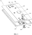
FIG. 3 illustrates an exploded schematic diagram of a top cover in a battery module according to an embodiment of the present application. -
FIG. 4 illustrates an exploded schematic diagram of a cell in a battery module according to an embodiment of the present application. -
FIG. 5 illustrates a schematic diagram of a cell group in a battery module according to an embodiment of the present application. -
FIG. 6 illustrates a schematic diagram of a voltage sampling terminal in a battery module according to an embodiment of the present application. -
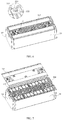
FIG. 7 illustrates schematic diagram showing assembling of a lower plastic part and a cell group in a battery module according to an embodiment of the present application. -
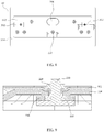
FIG. 8 illustrates a schematic diagram of a top cover in a battery module according to an embodiment of the present application. -
FIG. 9 illustrates a cross-sectional diagram along line A-A inFIG. 8 . -
FIG. 10 illustrates a cross-sectional diagram along line B-B inFIG. 8 . - In order to more clearly describe the objects, technical solutions and beneficial effects of the present application, the present application is illustrated with reference to the drawings and embodiments as follows. It should be noted that the described embodiments are merely used to explain the present application rather than to limit the present application.
- With reference to
FIGS. 1 ,3 and5 , the present disclosure provides a battery module. The battery module includes: a lower housing10; acell group 20 accommodated in thelower housing 10, and atop cover 30 sealed from and connected to thelower housing 10. Thecell group 20 includes a plurality ofcells 200. Thetop cover 30 includes an upperplastic part 312, a lowerplastic part 316, and ametal cover plate 314 located between the upperplastic part 312 and the lowerplastic part 316. Thetop cover 30 is provided with an explosion-proof valve 306 and amodule output electrode 302 electrically connected to thecell group 20. Anend plate 102 is provided at each of two ends of thelower housing 10. - With reference to
FIG. 4 and FIG. 5 , thecell 200 includes a celllower housing 202, a bare cell (not shown in the figures) accommodated in the celllower housing 202, and anupper cover 206 sealed from and connected to the celllower housing 202. Thelower housing 10 is made of metal, and both the celllower housing 202 and theupper cover 206 are made of electrolyte solution-resistant plastics in such an encapsulating way that the assembled cell can achieve a sealing and water-proof effect, thereby improving the safety performance of the whole battery module. The bare cell is electrically connected to anelectrode terminal 210 provided on thecell 200 by asoft connection 208. Theelectrode terminal 210 passes through theupper cover 206 and is fixed with theupper cover 206 by a first rivetingaluminum block 214. Asealing ring 212 is provided between theelectrode terminal 210 and theupper cover 206. Thesoft connection 208 is welded to an electrode tab of the bare cell and theelectrode terminal 210, thereby realizing electrical connection between the electrode tab and theelectrode terminal 210. The first rivetingaluminum block 214 and theelectrode terminal 210 are assembled in a manner of riveting, and a position where theelectrode terminal 210 passes through theupper cover 206 is sealed by compressing thesealing ring 212. Sealing of the whole cell housing is achieved in a manner of welding after theupper cover 206 and the celllower housing 202 are assembled. A rectangular-shaped boss 218 extends from the first rivetingaluminum block 214 along a long side of theupper cover 206, and thecell 200 is electrically connected to aconnection sheet 216 by the rectangular-shaped boss 218. - With reference to
FIGS. 5 ,6 ,8 and 9 , avoltage sampling terminal 220 is provided on theconnection sheet 216; thevoltage sampling terminal 220 passes through thetop cover 30, and is sealed form and fixed with thetop cover 30 by ascrew nut 224. Aninsulation sealing ring 222 is provided between thevoltage sampling terminal 220 and thetop cover 30, and thescrew nut 224 and thevoltage sampling terminal 220 are screwed tightly to compress theinsulation sealing ring 222, thereby sealing an opening for thevoltage sampling terminal 220 in thetop cover 30. The insulation of thevoltage sampling terminal 220 from thetop cover 30 is collectively achieved by theinsulation sealing ring 222, the lowerplastic part 316, and the upperplastic part 312. - With reference to
FIG. 7 , the lowerplastic part 316 is a hollow frame structure, a position of the lowerplastic part 316 corresponding to theconnection sheet 216 and thevoltage sampling terminal 220 is covered by an insulation separator, for realizing insulation between themetal cover plate 314 and any one of theconnection sheet 216 and thevoltage sampling terminal 220. - With reference to
FIGS. 3 ,8 and10 , themodule output electrode 302 includes amodule electrode terminal 320. Themodule electrode terminal 320 passes through thetop cover 30 and is sealed from and fixed with thetop cover 30 by a second rivetingaluminum block 324. Aninsulation sealing ring 322 is provided between themodule electrode terminal 320 and thetop cover 30. Thetop cover 30 further includes adeformable plate 326. Thedeformable plate 326 is configured to deform upwards to be electrically connected to the second rivetingaluminum block 324 and themodule electrode terminal 320 to form a protection loop when an internal pressure of the battery module is increased. - After the assembling of the battery module is accomplished, a pouring sealant or other organic resin is filled in an gap between the
lower housing 10 and thecell group 20, and the gap is fully filled so as to expel the remaining free space in thelower housing 10 after thecells 200 and other components are accommodated in thelower housing 10, for fixing thecells 200 and heat conduction. - Based on the embodiments of the present application as described above, compared with the related art, the battery module according to the present application at least achieves the following beneficial effects: 1) safety structures such as the
deformable plate 326 and the explosion-proof valve 306 are provided on thetop cover 30, and the safety structure for each single cellupper cover 206 is eliminated, which simplifies the assembling, saves the cost, and improves the safety performance and the energy density; 2) thetop cover 30 is sealed from and connected to thelower housing 10, which meets the requirement of IP67 protection grade and realizes the integration of the cell module; 3) the electrolyte solution-resistant non-metal insulation material is used to encapsulate the cells themselves, which saves the cost, improves sealing reliability, meets the requirement of insulation and durability against pressure, and improves moisture-proof performance; 4) the pouring sealant or organic resin is filled in the gap between thelower housing 10 and thecell group 20, which fixes thecells 200 and theconnection sheets 216, and prevents fracture of the cell encapsulation material due to a friction between thecells 200 and thelower housing 10. - Based on the description above, those skilled in the art can make suitable changes and modifications to the embodiments above, without departing from the principles of the present application. Therefore, the present application is not limited by the embodiments disclosed above, and the changes and modifications shall also fall into the protection scope of the present application. Besides, terms used in the description are merely intended for exemplary illustration rather than for limiting the present application.
Claims (10)
- A battery module, characterized in that, the battery module comprises:a lower housing (10);a cell group (20) accommodated in the lower housing (10), wherein the cell group (20) comprises a plurality of cells (200);a top cover (30) sealed from and connected to the lower housing (10), wherein the top cover (30) comprises an upper plastic part (312), a lower plastic part (316), and a metal cover plate (314) located between the upper plastic part (312) and the lower plastic part (316);an explosion-proof valve (306) provided on the top cover (30); anda module output electrode (302) provided on the top cover (30), wherein the module output electrode (302) is electrically connected to the cell group (20).
- The battery module according to claim 1, characterized in that, each of the plurality of cells (200) comprises a cell lower housing (10), a bare cell accommodated in the cell lower housing (10), and an upper cover (206) sealed from and connected to the cell lower housing (10).
- The battery module according to claim 2, characterized in that, the lower housing (10) is made of metal, and both the cell lower housing (10) and the upper cover (206) are made of a non-metal material which is insulative and electrolyte solution-resistant.
- The battery module according to claim 2, characterized in that, the bare cell is electrically connected to an electrode terminal (210) provided on the cell by a soft connection (208), the electrode terminal (210) passes through the upper cover (206) and is fixed with the upper cover (206) by a first riveting aluminum block (214), and a sealing ring (212) is provided between the electrode terminal (210) and the upper cover (206).
- The battery module according to claim 1, characterized in that, the battery module further comprises a connection sheet (216) electrically connected to the plurality of cells (200).
- The battery module according to claim 5, characterized in that, the battery module further comprises:a voltage sampling terminal (220) provided on the connection sheet (216), wherein the voltage sampling terminal (220) passes through the top cover (30) and is fixed with and sealed from and connected to the top cover (30) by a screw nut (224), anda sealing ring (212) provided between the voltage sampling terminal (220) and the top cover (30).
- The battery module according to claim 6, characterized in that, the lower plastic part (316) is a hollow frame structure and a position of the lower plastic part (316) corresponding to the connection sheet (216) and the voltage sampling terminal (220) is covered with an insulation separator.
- The battery module according to claim 1, characterized in that, the module output electrode (302) comprises a module electrode terminal (320), wherein the module electrode terminal (320) passes through the top cover (30) and is fixed with and sealed from the top cover (30) by a second riveting aluminum block (324), and wherein an insulation sealing ring (322) is provided between the module electrode terminal (320) and the top cover (30).
- The battery module according to claim 8, characterized in that, the top cover (30) further comprises a deformable plate (326), and the deformable plate (326) is configured to deform upwards to be electrically connected to the second riveting aluminum block (324) and the module electrode terminal (320) to form a protection loop when an internal pressure of the battery module is increased.
- The battery module according to any one of claims 1-9, characterized in that, a pouring sealant or an organic resin is filled in a gap between the lower housing (10) and the cell group (20).
Applications Claiming Priority (1)
| Application Number | Priority Date | Filing Date | Title |
|---|---|---|---|
| CN201710112115.3A CN108511660B (en) | 2017-02-28 | 2017-02-28 | Battery module |
Publications (2)
| Publication Number | Publication Date |
|---|---|
| EP3367494A1 true EP3367494A1 (en) | 2018-08-29 |
| EP3367494B1 EP3367494B1 (en) | 2022-02-09 |
Family
ID=61223768
Family Applications (1)
| Application Number | Title | Priority Date | Filing Date |
|---|---|---|---|
| EP18156584.7A Active EP3367494B1 (en) | 2017-02-28 | 2018-02-13 | Battery module |
Country Status (4)
| Country | Link |
|---|---|
| EP (1) | EP3367494B1 (en) |
| JP (1) | JP6592546B2 (en) |
| CN (1) | CN108511660B (en) |
| WO (1) | WO2018157558A1 (en) |
Cited By (5)
| Publication number | Priority date | Publication date | Assignee | Title |
|---|---|---|---|---|
| EP3540815A1 (en) * | 2018-03-16 | 2019-09-18 | Contemporary Amperex Technology Co., Limited | Battery module |
| US11600883B2 (en) | 2016-04-13 | 2023-03-07 | Semiconductor Energy Laboratory Co., Ltd. | Battery module, method for manufacturing battery module, and electronic device |
| US20230253653A1 (en) * | 2022-02-10 | 2023-08-10 | Eve Power Co., Ltd. | Battery cover assembly and cylindrical battery |
| US12148948B2 (en) | 2019-09-10 | 2024-11-19 | Vehicle Energy Japan Inc. | Battery pack |
| US12407046B2 (en) * | 2023-02-09 | 2025-09-02 | Hithium Tech Hk Limited | End cover assembly, energy storage apparatus, and electricity-consumption device |
Families Citing this family (17)
| Publication number | Priority date | Publication date | Assignee | Title |
|---|---|---|---|---|
| CN111048734B (en) * | 2018-10-11 | 2022-01-11 | 宁德时代新能源科技股份有限公司 | Battery module |
| DE102018125457A1 (en) * | 2018-10-15 | 2020-04-16 | Webasto SE | Insert part for insertion into a battery housing of a battery system arrangement and battery system arrangement |
| CN110571387A (en) * | 2019-10-12 | 2019-12-13 | 荣盛盟固利新能源科技有限公司 | Integrated battery module |
| WO2021185372A1 (en) * | 2020-03-20 | 2021-09-23 | 陈带秀 | Battery, manufacturing method therefor and use thereof |
| CN111276732A (en) * | 2020-03-30 | 2020-06-12 | 湖北亿纬动力有限公司 | A single battery and battery module |
| CN113594613B (en) * | 2020-04-30 | 2024-07-19 | 蜂巢能源科技有限公司 | Battery module, battery module processing technology and vehicle |
| CN111430592B (en) * | 2020-04-30 | 2022-04-22 | 蜂巢能源科技有限公司 | Cell cover, battery module and vehicle |
| CN113540636A (en) * | 2021-03-18 | 2021-10-22 | 欣旺达电动汽车电池有限公司 | Battery module and battery pack |
| CN113161651A (en) * | 2021-04-21 | 2021-07-23 | 宁德新能源科技有限公司 | Electrochemical device and electric equipment |
| CN113346183B (en) * | 2021-05-12 | 2023-05-05 | 中创新航技术研究院(江苏)有限公司 | Battery pack, battery module and battery pack |
| KR102890933B1 (en) * | 2021-06-08 | 2025-11-24 | 주식회사 엘지에너지솔루션 | Battery module having a cooling structure using Insulation coolant, and a battery pack and vehicle comprising the same |
| EP4350867A4 (en) * | 2021-08-30 | 2024-12-25 | Huawei Digital Power Technologies Co., Ltd. | BATTERY MODULE, BATTERY PACK AND ELECTRONIC DEVICE |
| CN114976396A (en) * | 2022-06-28 | 2022-08-30 | 广汽埃安新能源汽车有限公司 | Battery module and electric vehicle |
| WO2024044938A1 (en) * | 2022-08-30 | 2024-03-07 | 宁德时代新能源科技股份有限公司 | Battery cell, battery, and electric apparatus |
| CN115548415B (en) * | 2022-11-29 | 2023-02-28 | 中自环保科技股份有限公司 | Combination method of soft-packaged large cylindrical battery based on full tabs |
| CN116979124B (en) * | 2023-08-10 | 2024-05-28 | 浙江中泽精密科技股份有限公司 | A production process control method and system for explosion-proof valve of battery aluminum shell |
| CN119890597A (en) * | 2025-03-25 | 2025-04-25 | 宁德时代新能源科技股份有限公司 | Battery device and electricity utilization device |
Citations (6)
| Publication number | Priority date | Publication date | Assignee | Title |
|---|---|---|---|---|
| EP2523234A1 (en) * | 2011-05-13 | 2012-11-14 | LG Chem, Ltd. | Battery module and method for manufacturing the battery module |
| WO2013116044A1 (en) * | 2012-01-31 | 2013-08-08 | Johnson Controls Technology Company | Systems and methods for manufacturing battery cells |
| WO2015013544A1 (en) * | 2013-07-25 | 2015-01-29 | Johnson Controls Technology Company | Vent housing for advanced batteries |
| US20160036032A1 (en) * | 2014-07-31 | 2016-02-04 | Johnson Controls Technology Company | Overcharge protection device for a battery module |
| WO2016112411A1 (en) * | 2015-01-05 | 2016-07-14 | Johnson Controls Technology Company | Circuitry harness and pass through for lead wires of a battery module |
| US9595705B1 (en) * | 2016-03-03 | 2017-03-14 | Faraday&Future Inc. | Electric vehicle battery |
Family Cites Families (12)
| Publication number | Priority date | Publication date | Assignee | Title |
|---|---|---|---|---|
| JP4993935B2 (en) * | 2006-04-04 | 2012-08-08 | 三洋電機株式会社 | Assembled battery |
| JPWO2012133708A1 (en) * | 2011-03-31 | 2014-07-28 | 三洋電機株式会社 | Power supply device and vehicle equipped with power supply device |
| TWI473324B (en) * | 2011-11-21 | 2015-02-11 | Yamaha Motor Co Ltd | Battery |
| DE112013002593T5 (en) * | 2012-05-21 | 2015-02-12 | A 123 Systems, LLC | Lithium-ion batteries are multi-cell |
| GB2505871A (en) * | 2012-07-20 | 2014-03-19 | Williams Grand Prix Eng | Flame or heat resistant material comprising ceramic and carbon layers |
| CN203150627U (en) * | 2013-01-18 | 2013-08-21 | 宁德新能源科技有限公司 | Power battery top cover and power battery containing top cover |
| JP5841571B2 (en) * | 2013-07-31 | 2016-01-13 | 日立オートモティブシステムズ株式会社 | Secondary battery |
| JP6295557B2 (en) * | 2013-09-12 | 2018-03-20 | 株式会社Gsユアサ | Power storage device |
| CN105489811A (en) * | 2014-09-18 | 2016-04-13 | 中国电子科技集团公司第十八研究所 | Preparation method for safe battery pack |
| CN105098108B (en) * | 2015-07-23 | 2017-09-15 | 宁德时代新能源科技股份有限公司 | Power battery top cover structure and power battery |
| TWI555261B (en) * | 2015-08-10 | 2016-10-21 | 有量科技股份有限公司 | Lithium Battery Module |
| KR102392380B1 (en) * | 2015-08-19 | 2022-04-29 | 삼성에스디아이 주식회사 | Secondary battery |
-
2017
- 2017-02-28 CN CN201710112115.3A patent/CN108511660B/en active Active
- 2017-08-11 WO PCT/CN2017/097080 patent/WO2018157558A1/en not_active Ceased
-
2018
- 2018-02-13 EP EP18156584.7A patent/EP3367494B1/en active Active
- 2018-02-28 JP JP2018034444A patent/JP6592546B2/en active Active
Patent Citations (6)
| Publication number | Priority date | Publication date | Assignee | Title |
|---|---|---|---|---|
| EP2523234A1 (en) * | 2011-05-13 | 2012-11-14 | LG Chem, Ltd. | Battery module and method for manufacturing the battery module |
| WO2013116044A1 (en) * | 2012-01-31 | 2013-08-08 | Johnson Controls Technology Company | Systems and methods for manufacturing battery cells |
| WO2015013544A1 (en) * | 2013-07-25 | 2015-01-29 | Johnson Controls Technology Company | Vent housing for advanced batteries |
| US20160036032A1 (en) * | 2014-07-31 | 2016-02-04 | Johnson Controls Technology Company | Overcharge protection device for a battery module |
| WO2016112411A1 (en) * | 2015-01-05 | 2016-07-14 | Johnson Controls Technology Company | Circuitry harness and pass through for lead wires of a battery module |
| US9595705B1 (en) * | 2016-03-03 | 2017-03-14 | Faraday&Future Inc. | Electric vehicle battery |
Cited By (7)
| Publication number | Priority date | Publication date | Assignee | Title |
|---|---|---|---|---|
| US11600883B2 (en) | 2016-04-13 | 2023-03-07 | Semiconductor Energy Laboratory Co., Ltd. | Battery module, method for manufacturing battery module, and electronic device |
| US12374761B2 (en) | 2016-04-13 | 2025-07-29 | Semiconductor Energy Laboratory Co., Ltd. | Battery module, method for manufacturing battery module, and electronic device |
| EP3540815A1 (en) * | 2018-03-16 | 2019-09-18 | Contemporary Amperex Technology Co., Limited | Battery module |
| US10559798B2 (en) | 2018-03-16 | 2020-02-11 | Contemporary Amperex Technology Co., Limited | Battery module |
| US12148948B2 (en) | 2019-09-10 | 2024-11-19 | Vehicle Energy Japan Inc. | Battery pack |
| US20230253653A1 (en) * | 2022-02-10 | 2023-08-10 | Eve Power Co., Ltd. | Battery cover assembly and cylindrical battery |
| US12407046B2 (en) * | 2023-02-09 | 2025-09-02 | Hithium Tech Hk Limited | End cover assembly, energy storage apparatus, and electricity-consumption device |
Also Published As
| Publication number | Publication date |
|---|---|
| JP2018142540A (en) | 2018-09-13 |
| JP6592546B2 (en) | 2019-10-16 |
| CN108511660B (en) | 2020-08-28 |
| CN108511660A (en) | 2018-09-07 |
| EP3367494B1 (en) | 2022-02-09 |
| WO2018157558A1 (en) | 2018-09-07 |
Similar Documents
| Publication | Publication Date | Title |
|---|---|---|
| EP3367494B1 (en) | Battery module | |
| EP3460867B1 (en) | Battery box | |
| CN206490119U (en) | Battery modules | |
| US9118051B2 (en) | Battery and method of manufacturing the same | |
| CN101388445B (en) | a battery pack | |
| US20130040172A1 (en) | Structure of lithium-ion battery module | |
| US11303002B2 (en) | Secondary battery | |
| CN101315990A (en) | a battery pack | |
| CN110752324A (en) | Sealing assembly and lithium ion battery | |
| KR101222397B1 (en) | Battery pack | |
| CN111276732A (en) | A single battery and battery module | |
| WO2014091635A1 (en) | Layered battery and assembly method for layered battery | |
| ES2843498T3 (en) | Top cover assembly for the power battery and the power battery that has the same | |
| KR101735512B1 (en) | Secondary battery with improved structure of electrode lead and Method for manufacturing the same | |
| CN107112492A (en) | Storage element | |
| US20230299396A1 (en) | Battery assembly and preparation method, battery and electric vehicle | |
| CN218586131U (en) | Battery and electronic equipment | |
| CN109786644A (en) | Connection sheet, cover plate assembly and battery | |
| CN209929401U (en) | Utmost point ear and lithium ion battery with dysmorphism utmost point ear is glued | |
| EP2922073A1 (en) | Electricity storage device and electricity storage module | |
| CN119905737B (en) | Top cover assembly, energy storage device and power utilization system | |
| CN104282864A (en) | Cell capable of reducing or eliminating housing voltage and method for preparing same | |
| JP3938063B2 (en) | Storage element terminal structure and storage element | |
| CN214280064U (en) | Electricity core packaging structure of apron heat dissipation | |
| CN209592228U (en) | Secondary cell |
Legal Events
| Date | Code | Title | Description |
|---|---|---|---|
| PUAI | Public reference made under article 153(3) epc to a published international application that has entered the european phase |
Free format text: ORIGINAL CODE: 0009012 |
|
| STAA | Information on the status of an ep patent application or granted ep patent |
Free format text: STATUS: REQUEST FOR EXAMINATION WAS MADE |
|
| 17P | Request for examination filed |
Effective date: 20180213 |
|
| AK | Designated contracting states |
Kind code of ref document: A1 Designated state(s): AL AT BE BG CH CY CZ DE DK EE ES FI FR GB GR HR HU IE IS IT LI LT LU LV MC MK MT NL NO PL PT RO RS SE SI SK SM TR |
|
| AX | Request for extension of the european patent |
Extension state: BA ME |
|
| STAA | Information on the status of an ep patent application or granted ep patent |
Free format text: STATUS: EXAMINATION IS IN PROGRESS |
|
| 17Q | First examination report despatched |
Effective date: 20210122 |
|
| GRAP | Despatch of communication of intention to grant a patent |
Free format text: ORIGINAL CODE: EPIDOSNIGR1 |
|
| STAA | Information on the status of an ep patent application or granted ep patent |
Free format text: STATUS: GRANT OF PATENT IS INTENDED |
|
| RIC1 | Information provided on ipc code assigned before grant |
Ipc: H01M 10/48 20060101AFI20211004BHEP |
|
| INTG | Intention to grant announced |
Effective date: 20211102 |
|
| GRAS | Grant fee paid |
Free format text: ORIGINAL CODE: EPIDOSNIGR3 |
|
| GRAA | (expected) grant |
Free format text: ORIGINAL CODE: 0009210 |
|
| STAA | Information on the status of an ep patent application or granted ep patent |
Free format text: STATUS: THE PATENT HAS BEEN GRANTED |
|
| AK | Designated contracting states |
Kind code of ref document: B1 Designated state(s): AL AT BE BG CH CY CZ DE DK EE ES FI FR GB GR HR HU IE IS IT LI LT LU LV MC MK MT NL NO PL PT RO RS SE SI SK SM TR |
|
| REG | Reference to a national code |
Ref country code: GB Ref legal event code: FG4D |
|
| REG | Reference to a national code |
Ref country code: CH Ref legal event code: EP Ref country code: AT Ref legal event code: REF Ref document number: 1468057 Country of ref document: AT Kind code of ref document: T Effective date: 20220215 |
|
| REG | Reference to a national code |
Ref country code: IE Ref legal event code: FG4D |
|
| REG | Reference to a national code |
Ref country code: DE Ref legal event code: R096 Ref document number: 602018030488 Country of ref document: DE |
|
| REG | Reference to a national code |
Ref country code: FI Ref legal event code: FGE |
|
| REG | Reference to a national code |
Ref country code: LT Ref legal event code: MG9D |
|
| REG | Reference to a national code |
Ref country code: NL Ref legal event code: MP Effective date: 20220209 |
|
| REG | Reference to a national code |
Ref country code: AT Ref legal event code: MK05 Ref document number: 1468057 Country of ref document: AT Kind code of ref document: T Effective date: 20220209 |
|
| PG25 | Lapsed in a contracting state [announced via postgrant information from national office to epo] |
Ref country code: SE Free format text: LAPSE BECAUSE OF FAILURE TO SUBMIT A TRANSLATION OF THE DESCRIPTION OR TO PAY THE FEE WITHIN THE PRESCRIBED TIME-LIMIT Effective date: 20220209 Ref country code: RS Free format text: LAPSE BECAUSE OF FAILURE TO SUBMIT A TRANSLATION OF THE DESCRIPTION OR TO PAY THE FEE WITHIN THE PRESCRIBED TIME-LIMIT Effective date: 20220209 Ref country code: PT Free format text: LAPSE BECAUSE OF FAILURE TO SUBMIT A TRANSLATION OF THE DESCRIPTION OR TO PAY THE FEE WITHIN THE PRESCRIBED TIME-LIMIT Effective date: 20220609 Ref country code: NO Free format text: LAPSE BECAUSE OF FAILURE TO SUBMIT A TRANSLATION OF THE DESCRIPTION OR TO PAY THE FEE WITHIN THE PRESCRIBED TIME-LIMIT Effective date: 20220509 Ref country code: NL Free format text: LAPSE BECAUSE OF FAILURE TO SUBMIT A TRANSLATION OF THE DESCRIPTION OR TO PAY THE FEE WITHIN THE PRESCRIBED TIME-LIMIT Effective date: 20220209 Ref country code: LT Free format text: LAPSE BECAUSE OF FAILURE TO SUBMIT A TRANSLATION OF THE DESCRIPTION OR TO PAY THE FEE WITHIN THE PRESCRIBED TIME-LIMIT Effective date: 20220209 Ref country code: HR Free format text: LAPSE BECAUSE OF FAILURE TO SUBMIT A TRANSLATION OF THE DESCRIPTION OR TO PAY THE FEE WITHIN THE PRESCRIBED TIME-LIMIT Effective date: 20220209 Ref country code: ES Free format text: LAPSE BECAUSE OF FAILURE TO SUBMIT A TRANSLATION OF THE DESCRIPTION OR TO PAY THE FEE WITHIN THE PRESCRIBED TIME-LIMIT Effective date: 20220209 Ref country code: BG Free format text: LAPSE BECAUSE OF FAILURE TO SUBMIT A TRANSLATION OF THE DESCRIPTION OR TO PAY THE FEE WITHIN THE PRESCRIBED TIME-LIMIT Effective date: 20220509 |
|
| PG25 | Lapsed in a contracting state [announced via postgrant information from national office to epo] |
Ref country code: PL Free format text: LAPSE BECAUSE OF FAILURE TO SUBMIT A TRANSLATION OF THE DESCRIPTION OR TO PAY THE FEE WITHIN THE PRESCRIBED TIME-LIMIT Effective date: 20220209 Ref country code: LV Free format text: LAPSE BECAUSE OF FAILURE TO SUBMIT A TRANSLATION OF THE DESCRIPTION OR TO PAY THE FEE WITHIN THE PRESCRIBED TIME-LIMIT Effective date: 20220209 Ref country code: GR Free format text: LAPSE BECAUSE OF FAILURE TO SUBMIT A TRANSLATION OF THE DESCRIPTION OR TO PAY THE FEE WITHIN THE PRESCRIBED TIME-LIMIT Effective date: 20220510 Ref country code: AT Free format text: LAPSE BECAUSE OF FAILURE TO SUBMIT A TRANSLATION OF THE DESCRIPTION OR TO PAY THE FEE WITHIN THE PRESCRIBED TIME-LIMIT Effective date: 20220209 |
|
| PG25 | Lapsed in a contracting state [announced via postgrant information from national office to epo] |
Ref country code: IS Free format text: LAPSE BECAUSE OF FAILURE TO SUBMIT A TRANSLATION OF THE DESCRIPTION OR TO PAY THE FEE WITHIN THE PRESCRIBED TIME-LIMIT Effective date: 20220609 |
|
| REG | Reference to a national code |
Ref country code: CH Ref legal event code: PL |
|
| REG | Reference to a national code |
Ref country code: BE Ref legal event code: MM Effective date: 20220228 |
|
| PG25 | Lapsed in a contracting state [announced via postgrant information from national office to epo] |
Ref country code: SM Free format text: LAPSE BECAUSE OF FAILURE TO SUBMIT A TRANSLATION OF THE DESCRIPTION OR TO PAY THE FEE WITHIN THE PRESCRIBED TIME-LIMIT Effective date: 20220209 Ref country code: SK Free format text: LAPSE BECAUSE OF FAILURE TO SUBMIT A TRANSLATION OF THE DESCRIPTION OR TO PAY THE FEE WITHIN THE PRESCRIBED TIME-LIMIT Effective date: 20220209 Ref country code: RO Free format text: LAPSE BECAUSE OF FAILURE TO SUBMIT A TRANSLATION OF THE DESCRIPTION OR TO PAY THE FEE WITHIN THE PRESCRIBED TIME-LIMIT Effective date: 20220209 Ref country code: LU Free format text: LAPSE BECAUSE OF NON-PAYMENT OF DUE FEES Effective date: 20220213 Ref country code: EE Free format text: LAPSE BECAUSE OF FAILURE TO SUBMIT A TRANSLATION OF THE DESCRIPTION OR TO PAY THE FEE WITHIN THE PRESCRIBED TIME-LIMIT Effective date: 20220209 Ref country code: DK Free format text: LAPSE BECAUSE OF FAILURE TO SUBMIT A TRANSLATION OF THE DESCRIPTION OR TO PAY THE FEE WITHIN THE PRESCRIBED TIME-LIMIT Effective date: 20220209 Ref country code: CZ Free format text: LAPSE BECAUSE OF FAILURE TO SUBMIT A TRANSLATION OF THE DESCRIPTION OR TO PAY THE FEE WITHIN THE PRESCRIBED TIME-LIMIT Effective date: 20220209 |
|
| REG | Reference to a national code |
Ref country code: DE Ref legal event code: R097 Ref document number: 602018030488 Country of ref document: DE |
|
| PG25 | Lapsed in a contracting state [announced via postgrant information from national office to epo] |
Ref country code: MC Free format text: LAPSE BECAUSE OF FAILURE TO SUBMIT A TRANSLATION OF THE DESCRIPTION OR TO PAY THE FEE WITHIN THE PRESCRIBED TIME-LIMIT Effective date: 20220209 Ref country code: AL Free format text: LAPSE BECAUSE OF FAILURE TO SUBMIT A TRANSLATION OF THE DESCRIPTION OR TO PAY THE FEE WITHIN THE PRESCRIBED TIME-LIMIT Effective date: 20220209 |
|
| PLBE | No opposition filed within time limit |
Free format text: ORIGINAL CODE: 0009261 |
|
| STAA | Information on the status of an ep patent application or granted ep patent |
Free format text: STATUS: NO OPPOSITION FILED WITHIN TIME LIMIT |
|
| 26N | No opposition filed |
Effective date: 20221110 |
|
| PG25 | Lapsed in a contracting state [announced via postgrant information from national office to epo] |
Ref country code: LI Free format text: LAPSE BECAUSE OF NON-PAYMENT OF DUE FEES Effective date: 20220228 Ref country code: IE Free format text: LAPSE BECAUSE OF NON-PAYMENT OF DUE FEES Effective date: 20220213 Ref country code: CH Free format text: LAPSE BECAUSE OF NON-PAYMENT OF DUE FEES Effective date: 20220228 |
|
| PG25 | Lapsed in a contracting state [announced via postgrant information from national office to epo] |
Ref country code: SI Free format text: LAPSE BECAUSE OF FAILURE TO SUBMIT A TRANSLATION OF THE DESCRIPTION OR TO PAY THE FEE WITHIN THE PRESCRIBED TIME-LIMIT Effective date: 20220209 Ref country code: BE Free format text: LAPSE BECAUSE OF NON-PAYMENT OF DUE FEES Effective date: 20220228 |
|
| P01 | Opt-out of the competence of the unified patent court (upc) registered |
Effective date: 20230516 |
|
| PG25 | Lapsed in a contracting state [announced via postgrant information from national office to epo] |
Ref country code: IT Free format text: LAPSE BECAUSE OF FAILURE TO SUBMIT A TRANSLATION OF THE DESCRIPTION OR TO PAY THE FEE WITHIN THE PRESCRIBED TIME-LIMIT Effective date: 20220209 |
|
| PG25 | Lapsed in a contracting state [announced via postgrant information from national office to epo] |
Ref country code: HU Free format text: LAPSE BECAUSE OF FAILURE TO SUBMIT A TRANSLATION OF THE DESCRIPTION OR TO PAY THE FEE WITHIN THE PRESCRIBED TIME-LIMIT; INVALID AB INITIO Effective date: 20180213 |
|
| PG25 | Lapsed in a contracting state [announced via postgrant information from national office to epo] |
Ref country code: MK Free format text: LAPSE BECAUSE OF FAILURE TO SUBMIT A TRANSLATION OF THE DESCRIPTION OR TO PAY THE FEE WITHIN THE PRESCRIBED TIME-LIMIT Effective date: 20220209 Ref country code: CY Free format text: LAPSE BECAUSE OF FAILURE TO SUBMIT A TRANSLATION OF THE DESCRIPTION OR TO PAY THE FEE WITHIN THE PRESCRIBED TIME-LIMIT Effective date: 20220209 |
|
| REG | Reference to a national code |
Ref country code: DE Ref legal event code: R081 Ref document number: 602018030488 Country of ref document: DE Owner name: CONTEMPORARY AMPEREX TECHNOLOGY (HONG KONG) LT, HK Free format text: FORMER OWNER: CONTEMPORARY AMPEREX TECHNOLOGY CO., LIMITED, NINGDE CITY, FUJIAN, CN |
|
| REG | Reference to a national code |
Ref country code: GB Ref legal event code: 732E Free format text: REGISTERED BETWEEN 20240801 AND 20240807 |
|
| PG25 | Lapsed in a contracting state [announced via postgrant information from national office to epo] |
Ref country code: MT Free format text: LAPSE BECAUSE OF FAILURE TO SUBMIT A TRANSLATION OF THE DESCRIPTION OR TO PAY THE FEE WITHIN THE PRESCRIBED TIME-LIMIT Effective date: 20220209 |
|
| REG | Reference to a national code |
Ref country code: FI Ref legal event code: PCE Owner name: CONTEMPORARY AMPEREX TECHNOLOGY (HONG KONG) LIMITED |
|
| PG25 | Lapsed in a contracting state [announced via postgrant information from national office to epo] |
Ref country code: TR Free format text: LAPSE BECAUSE OF FAILURE TO SUBMIT A TRANSLATION OF THE DESCRIPTION OR TO PAY THE FEE WITHIN THE PRESCRIBED TIME-LIMIT Effective date: 20220209 |
|
| PGFP | Annual fee paid to national office [announced via postgrant information from national office to epo] |
Ref country code: FI Payment date: 20251230 Year of fee payment: 9 |
|
| PGFP | Annual fee paid to national office [announced via postgrant information from national office to epo] |
Ref country code: FR Payment date: 20251208 Year of fee payment: 9 |
|
| PGFP | Annual fee paid to national office [announced via postgrant information from national office to epo] |
Ref country code: GB Payment date: 20260106 Year of fee payment: 9 |
|
| PGFP | Annual fee paid to national office [announced via postgrant information from national office to epo] |
Ref country code: DE Payment date: 20251216 Year of fee payment: 9 |