EP3367080A1 - Contactless method for measuring torque - Google Patents
Contactless method for measuring torque Download PDFInfo
- Publication number
- EP3367080A1 EP3367080A1 EP16857413.5A EP16857413A EP3367080A1 EP 3367080 A1 EP3367080 A1 EP 3367080A1 EP 16857413 A EP16857413 A EP 16857413A EP 3367080 A1 EP3367080 A1 EP 3367080A1
- Authority
- EP
- European Patent Office
- Prior art keywords
- metal rotating
- torque
- rotating bodies
- measuring
- rotating body
- Prior art date
- Legal status (The legal status is an assumption and is not a legal conclusion. Google has not performed a legal analysis and makes no representation as to the accuracy of the status listed.)
- Withdrawn
Links
- 238000000034 method Methods 0.000 title claims abstract description 43
- 238000001514 detection method Methods 0.000 claims abstract description 37
- 239000002184 metal Substances 0.000 claims abstract description 32
- 239000003550 marker Substances 0.000 claims abstract description 26
- 230000005540 biological transmission Effects 0.000 claims abstract description 15
- 230000005674 electromagnetic induction Effects 0.000 claims abstract description 4
- 238000005070 sampling Methods 0.000 claims description 22
- 230000005484 gravity Effects 0.000 claims description 20
- 230000008878 coupling Effects 0.000 claims description 12
- 238000010168 coupling process Methods 0.000 claims description 12
- 238000005859 coupling reaction Methods 0.000 claims description 12
- 230000001939 inductive effect Effects 0.000 claims description 7
- 238000005259 measurement Methods 0.000 abstract description 8
- 239000000428 dust Substances 0.000 abstract description 5
- 230000005856 abnormality Effects 0.000 abstract description 4
- 230000007257 malfunction Effects 0.000 abstract description 4
- 230000006698 induction Effects 0.000 abstract 1
- 238000000691 measurement method Methods 0.000 abstract 1
- 230000002093 peripheral effect Effects 0.000 description 9
- 230000000630 rising effect Effects 0.000 description 4
- 238000007796 conventional method Methods 0.000 description 3
- 230000003287 optical effect Effects 0.000 description 3
- 239000002689 soil Substances 0.000 description 3
- 230000000694 effects Effects 0.000 description 2
- 238000005520 cutting process Methods 0.000 description 1
- 238000006073 displacement reaction Methods 0.000 description 1
- 238000004519 manufacturing process Methods 0.000 description 1
- 239000007769 metal material Substances 0.000 description 1
Images


Classifications
-
- G—PHYSICS
- G01—MEASURING; TESTING
- G01L—MEASURING FORCE, STRESS, TORQUE, WORK, MECHANICAL POWER, MECHANICAL EFFICIENCY, OR FLUID PRESSURE
- G01L3/00—Measuring torque, work, mechanical power, or mechanical efficiency, in general
- G01L3/02—Rotary-transmission dynamometers
- G01L3/04—Rotary-transmission dynamometers wherein the torque-transmitting element comprises a torsionally-flexible shaft
- G01L3/10—Rotary-transmission dynamometers wherein the torque-transmitting element comprises a torsionally-flexible shaft involving electric or magnetic means for indicating
- G01L3/101—Rotary-transmission dynamometers wherein the torque-transmitting element comprises a torsionally-flexible shaft involving electric or magnetic means for indicating involving magnetic or electromagnetic means
- G01L3/105—Rotary-transmission dynamometers wherein the torque-transmitting element comprises a torsionally-flexible shaft involving electric or magnetic means for indicating involving magnetic or electromagnetic means involving inductive means
Definitions
- the present invention relates to a non-contact torque measuring method for measuring magnitude of a transmission torque with a non-contact structure in a rotary torque transmission system.
- the torque is calculated by measuring an amount of strain while using a strain gauge (a strain gauge system), for example, in the case of measuring the magnitude of the transmission torque in a diaphragm coupling.
- a strain gauge a strain gauge system
- the present invention is made by taking the above points into consideration, and an object of the present invention is to provide a non-contact torque measuring method which is hard to generate failure or abnormality due to exercise load, can reduce the number of parts and an assembling man hour necessary for torque detection, is hard to generate malfunction or impossibility of measurement due to the dust, the oil or the soil, and does not necessarily form the device as the sealed structure.
- a non-contact torque measuring method for measuring a torque which is transmitted between a drive side metal rotating body and a driven side metal rotating body in a torque transmission system, the method comprising the steps of adjacently arranging detection portions each constructed by an electromagnetic coil in relation to the metal rotating bodies which are provided with concavo-convex marker portions in a part on a circumference or an end surface in an axial direction in a non-contact manner, detecting a distance between the detection portions and the metal rotating bodies and positions of the marker portions by generating an electromagnetic induction between the detection portions and the metal rotating bodies, and measuring an inductive load in the detection portions, and calculating a transmission torque value by measuring a rotating speed and a rotational phase difference of the marker portions generated in both the metal rotating bodies according to the torque transmission so as to compute.
- a non-contact torque measuring method is the non-contact torque measuring method described in the first aspect mentioned above, wherein a position of center of gravity in a pulsed sampling data is set to a reference point for phase detection when measuring the rotational phase difference.
- a non-contact torque measuring method is the non-contact torque measuring method described in the first or second aspect mentioned above, wherein the drive side metal rotating body and the driven side metal rotating body are a drive side diaphragm and a driven side diaphragm in a diaphragm coupling.
- the non-contact torque measuring method having the above structure is structured such as to (a) measure a minute concavity and convexity (marker portion) of the metal rotating body in a non-contact manner by measuring the distance of the electromagnetic induction system, (b) detect the concavity and convexity (marker portion) provided on an outer peripheral surface or an end surface of the metal rotating body (a diaphragm), and (c) detect the phase difference of the pulses generated from two rotating bodies on the basis of the detection of the concavity and convexity (marker portion) and measure the torque.
- the present invention achieves the following effects.
- the concavo-convex marker portion is attached to the metal rotating body and the detection body such as the strain gauge or the magnetic disc is not assembled.
- the detection body such as the strain gauge or the magnetic disc
- the failure or the abnormality is not generated in the detection body due to the rotational load.
- the concavo-convex marker portion can be formed minute, the structure becomes simple, and is not necessarily formed as the sealed structure. Further, freedom for arranging the detection portions is increased. Furthermore, since the distance to the surface of the metal rotating body is measured, the malfunction or the impossible measurement is hard to be generated due to the dust the oil or the soil.
- a non-contact torque measuring method is structured such as to measure magnitude of a transmission torque which is transmitted between a drive side diaphragm (a drive side metal rotating body) and a driven side diaphragm (a driven side metal rotating body) in a diaphragm coupling as a torque transmission system.
- a diaphragm coupling 1 is formed by coupling a drive side diaphragm 2 and a driven side diaphragm 3 via a center tube 4, and transmits the torque from the drive side diaphragm 2 to the driven side diaphragm 3 via the center tube 4.
- the drive side diaphragm 2 is sandwiched between a drive side flange 5 and a guard 6, and the drive side flange 5 is connected to a rotating shaft (not shown) in a drive side.
- the driven side diaphragm 3 is sandwiched between a driven side flange 7 and a guard 8, and the driven side flange 7 is connected to a rotating shaft (not shown) in a driven side.
- Each of the drive side diaphragm 2 and the driven side diaphragm 3 is made of a metal material having a conductive property.
- circumferentially partial concavo-convex marker portions 9 and 10 are provided respectively in an outer peripheral portion (an outer peripheral surface or an end surface in an axial direction) of the drive side diaphragm 2 and an outer peripheral portion (an outer peripheral surface or an end surface in an axial direction) of the driven side diaphragm 3 so as to be aligned their circumferential positions (if an amount of misalignment of the concavo-convex marker portions 9 and 10 is previously known, it is not necessary to align circumferentially).
- a circumferentially partial concave portion is formed by a cutting process, and a circumferentially partial convex portion may be formed by applying a stainless seal having a thickness between about 0.1 and 0.2 mm to an outer peripheral portion of each of the diaphragms 2 and 3, for example.
- Fig. 1 also shows a structure of a non-contact torque measuring device which is attached to the diaphragm coupling 1 mentioned above.
- the circumferentially partial concavo-convex marker portions 9 and 10 are respectively provided in the outer peripheral portion of the drive side diaphragm 2 and the outer peripheral portion of the driven side diaphragm 3 so as to be aligned circumferentially, and detection portions 11 and 12 each constructed by an electromagnetic coil are arranged in a non-contact manner at positions which are away from each other at a fixed distance in an outer peripheral side of each of the diaphragms 2 and 3.
- the detection portions (coils) 11 and 12 are connected to an inductive load sensor main body 15 and a measurement MPU 16 via cables 13 and 14.
- the inductive load sensor main body 15 oscillates the detection portions (coils) 11 and 12, and measures a distance between the detection portions (coils) 11 and 12 and the diaphragms 2 and 3 on the basis of a load fluctuation thereof.
- the distance between the detection portions (coils) 11 and 12 and the diaphragms 2 and 3 is changed in the concavo-convex marker portions 9 and 10 in comparison with the other portions to which a concavo-convex process is not applied.
- the concavo-convex marker portions 9 and 10 serve as a marker for detecting rotation.
- An inexpensive PCB pattern coil can be used as the detection portions (coils) 11 and 12.
- an output waveform of the inductive load fluctuation of the detection portions (coils) 11 and 12 comes to, for example, as shown in Fig. 2 . Since this example shows a waveform data which is actually measured when the concaving process is carried out in place of the convexing process as the concavo-convex marker portions 9 and 10, a load value is extremely lowered at positions P1 to P4 of the markers 9 and 10.
- the detection portions (coils) 11 and 12 adjacently arranged in a non-contact manner in relation to both the diaphragms 2 and 3 appropriately adjust so that phases of both the detection portions (coils) 11 and 12 are aligned as shown in Fig. 3 at the no-load time or the low-speed rotating time.
- the adjustment is mechanically carried out, or is carried out on an electric circuit or on software.
- a line A indicates the detection portion 11 in the drive side and a line B indicates the detection portion 12 in the driven side.
- a value of the transmission torque is determined by detecting the phase difference and carrying out a computing process with the measurement MPU 16 on the basis of the rotating speed and the phase difference.
- the concavo-convex marker portions 9 and 10 may be provided in the flanges 5 and 7 or the guards 6 and 8 which are bonded to the diaphragms 2 and 3, in place of the diaphragms 2 and 3.
- the measuring method according to the present invention is effective in the case of measuring the torque in the drive side and the driven side of two metal rotating bodies and the circular column connecting them, without being limited to the diaphragm coupling.
- the method pulses the data of the marker portion and sets the position of the rising edge where the rising of the sampling data and the threshold (the threshold value) intersect to the reference point for phase detection (the reference point achieved by the edge).
- the method takes a look at only whether the sampling data is greater or smaller than the threshold and does not take into consideration a quantitative change of the sampling data.
- the center of gravity is determined by setting the sampling data indicating the value which is equal to or less than the threshold to the data of subject to be calculated.
- the method determines a total of the data of subject to be calculated, sequentially subtracts each of the data of subject to be calculated from one half of the total data, and sets the data of subject to be calculated at the timing when the result of subtraction is equal to or less than 0 to the sampling data including the center of gravity.
- the method determines the position within the sampling time from a rate between the sampling data including the center of gravity and a residual value so as to set to the center of gravity.
- the threshold used for calculating the center of gravity is a threshold which is decided by a variable threshold described later. One sampling time is set to an optimal time on the basis of a used condition such as a rotating speed.
- the values of the sampling data to be calculated are first of all summed.
- the method calculates the difference data of subject to be calculated obtained by subtracting the data of subject to be calculated from the threshold every data of subject to be calculated, and sums the difference data of subject to be calculated, as shown in Fig. 6B .
- the method sequentially subtracts each of the difference data of subject to be calculated from one half of the total data mentioned above from the beginning, and sets the point where the result of subtraction is equal to or less than 0 to the sampling data where the center of gravity exists.
- the method calculates the center of gravity on the basis of the rate between the sampling data at the position of the center of gravity mentioned above and the residual value, and decides the position of the center of gravity in relation to the sampling time.
- the center of gravity is determined at the position of 15us among 75us of the position data of the center of gravity, as shown in Fig. 7 .
- the user of the device decides the threshold and sets it in the register, however, in the case that any eccentricity is generated by the rotation or in the case that any displacement exists in the axial direction, it is expected that the base value of the center data fluctuates, and the set threshold value deflects from the appropriate condition. Consequently, the precision for pulsing can be improved by automatically deciding the optimal threshold while reflecting the current base value.
- the method determines the threshold in relation to the next pulse or its own pulse after one rotation on the basis of the current pulse. More specifically, the method first of all maintains the minimum value of the pulse period as shown in Fig. 8 . Next, the method waits for one half time of the pulse period after the end of the pulse period. The method determines the base value on the basis of an average of the sampling data after time elapse. Next, the method calculates the threshold on the basis of the average of the minimum value and the base value. According to the method, it is possible to give an offset to the trailing and rising thresholds by the register setting. The average number of the base value is set to the sampling data number for the pulse period.
Landscapes
- Physics & Mathematics (AREA)
- Electromagnetism (AREA)
- General Physics & Mathematics (AREA)
- Force Measurement Appropriate To Specific Purposes (AREA)
- Testing Of Devices, Machine Parts, Or Other Structures Thereof (AREA)
- Arrangements For Transmission Of Measured Signals (AREA)
Abstract
Description
- The present invention relates to a non-contact torque measuring method for measuring magnitude of a transmission torque with a non-contact structure in a rotary torque transmission system.
- In the conventional technique, the torque is calculated by measuring an amount of strain while using a strain gauge (a strain gauge system), for example, in the case of measuring the magnitude of the transmission torque in a diaphragm coupling. In addition, there has been developed a technique of calculating the torque on the basis of a rotational phase difference by measuring rotation with an optical reading system utilizing an optical system or with a magnetic head reading system assembling a magnetic disc in a rotating part.
-
- Patent Document 1: Japanese Unexamined Utility Model Publication No.
62-155338 - Patent Document 2: Japanese Unexamined Utility Model Publication No.
2-88140 - However, the following problems are pointed out in these conventional techniques.
- (1) In the strain gauge system and the magnetic head reading system, detection bodies such as the strain gauge and the magnetic disc are assembled in a rotating part of a coupling. As a result, an exercise load always acts on the detection bodies. Therefore, any failure or abnormality may be generated in the detection body since the exercise load always acts on the detection body. Further, since the number of parts and an assembling man hour of the measurement device are great in the systems, a manufacturing cost of the device is expensive.
- (2) In the optical reading system, malfunction may be generated due to dust in the case that the dust is generated in a periphery of a reading part. Further, oil or a soil is attached to the reading part and it may be accordingly impossible to measure.
- (3) In the magnetic head reading system, it is necessary to form the device as a sealed structure since high-speed rotation of a gear portion is dangerous.
- The present invention is made by taking the above points into consideration, and an object of the present invention is to provide a non-contact torque measuring method which is hard to generate failure or abnormality due to exercise load, can reduce the number of parts and an assembling man hour necessary for torque detection, is hard to generate malfunction or impossibility of measurement due to the dust, the oil or the soil, and does not necessarily form the device as the sealed structure.
- In order to achieve the above object, a non-contact torque measuring method according to a first aspect of the present invention is a torque measuring method for measuring a torque which is transmitted between a drive side metal rotating body and a driven side metal rotating body in a torque transmission system, the method comprising the steps of adjacently arranging detection portions each constructed by an electromagnetic coil in relation to the metal rotating bodies which are provided with concavo-convex marker portions in a part on a circumference or an end surface in an axial direction in a non-contact manner, detecting a distance between the detection portions and the metal rotating bodies and positions of the marker portions by generating an electromagnetic induction between the detection portions and the metal rotating bodies, and measuring an inductive load in the detection portions, and calculating a transmission torque value by measuring a rotating speed and a rotational phase difference of the marker portions generated in both the metal rotating bodies according to the torque transmission so as to compute.
- Further, a non-contact torque measuring method according to a second aspect of the present invention is the non-contact torque measuring method described in the first aspect mentioned above, wherein a position of center of gravity in a pulsed sampling data is set to a reference point for phase detection when measuring the rotational phase difference.
- Further, a non-contact torque measuring method according to a third aspect of the present invention is the non-contact torque measuring method described in the first or second aspect mentioned above, wherein the drive side metal rotating body and the driven side metal rotating body are a drive side diaphragm and a driven side diaphragm in a diaphragm coupling.
- The non-contact torque measuring method according to the present invention having the above structure is structured such as to (a) measure a minute concavity and convexity (marker portion) of the metal rotating body in a non-contact manner by measuring the distance of the electromagnetic induction system, (b) detect the concavity and convexity (marker portion) provided on an outer peripheral surface or an end surface of the metal rotating body (a diaphragm), and (c) detect the phase difference of the pulses generated from two rotating bodies on the basis of the detection of the concavity and convexity (marker portion) and measure the torque.
- The present invention achieves the following effects.
- More specifically, according to the present invention, the concavo-convex marker portion is attached to the metal rotating body and the detection body such as the strain gauge or the magnetic disc is not assembled. As a result, the failure or the abnormality is not generated in the detection body due to the rotational load. Further, it is possible to widely reduce the number of parts and the assembling man hour which are necessary for detecting the torque. Further, since the concavo-convex marker portion can be formed minute, the structure becomes simple, and is not necessarily formed as the sealed structure. Further, freedom for arranging the detection portions is increased. Furthermore, since the distance to the surface of the metal rotating body is measured, the malfunction or the impossible measurement is hard to be generated due to the dust the oil or the soil.
-
-
Fig. 1 is an explanatory view of a diaphragm coupling which is a subject to be measured in a non-contact torque measuring method according to an embodiment of the present invention and an explanatory view of a non-contact torque measuring device; -
Fig. 2 is an explanatory view showing an inductive load waveform; -
Fig. 3 is an explanatory view showing an output waveform at the rotating time with no load and low speed; -
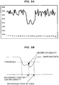
Fig. 4 is an explanatory view showing an output waveform at the rotating time with load and high speed; -
Fig. 5A is an explanatory view showing an actually measured data of a marker portion; -
Fig. 5B is an explanatory view showing a reference point for a cycle calculation; -
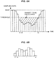
Fig. 6A is an explanatory view showing a sampling data of the marker portion; -
Fig. 6B is an explanatory view showing a difference data of subject to be calculated; -
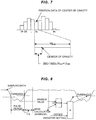
Fig. 7 is an explanatory view showing a position of center of gravity of the sampling time; and -
Fig. 8 is an explanatory view showing a variable threshold. - Next, a description will be given of an embodiment according to the present invention with reference to the accompanying drawings.
- A non-contact torque measuring method according to the embodiment is structured such as to measure magnitude of a transmission torque which is transmitted between a drive side diaphragm (a drive side metal rotating body) and a driven side diaphragm (a driven side metal rotating body) in a diaphragm coupling as a torque transmission system.
- As shown in
Fig. 1 , adiaphragm coupling 1 is formed by coupling adrive side diaphragm 2 and a drivenside diaphragm 3 via acenter tube 4, and transmits the torque from thedrive side diaphragm 2 to the drivenside diaphragm 3 via thecenter tube 4. Thedrive side diaphragm 2 is sandwiched between adrive side flange 5 and aguard 6, and thedrive side flange 5 is connected to a rotating shaft (not shown) in a drive side. The drivenside diaphragm 3 is sandwiched between a drivenside flange 7 and aguard 8, and the drivenside flange 7 is connected to a rotating shaft (not shown) in a driven side. Each of thedrive side diaphragm 2 and the drivenside diaphragm 3 is made of a metal material having a conductive property. - As a peculiar structure to the present invention in the
diaphragm coupling 1 mentioned above, circumferentially partial concavo-convex marker portions drive side diaphragm 2 and an outer peripheral portion (an outer peripheral surface or an end surface in an axial direction) of the drivenside diaphragm 3 so as to be aligned their circumferential positions (if an amount of misalignment of the concavo-convex marker portions convex marker portions diaphragms -
Fig. 1 also shows a structure of a non-contact torque measuring device which is attached to thediaphragm coupling 1 mentioned above. - As mentioned above, the circumferentially partial concavo-
convex marker portions drive side diaphragm 2 and the outer peripheral portion of the drivenside diaphragm 3 so as to be aligned circumferentially, anddetection portions diaphragms main body 15 and ameasurement MPU 16 viacables main body 15 oscillates the detection portions (coils) 11 and 12, and measures a distance between the detection portions (coils) 11 and 12 and thediaphragms diaphragms convex marker portions convex marker portions - Next, a description will be given of a torque calculating method on the basis of the measurement of distance mentioned above.
- When rotating, an output waveform of the inductive load fluctuation of the detection portions (coils) 11 and 12 comes to, for example, as shown in
Fig. 2 . Since this example shows a waveform data which is actually measured when the concaving process is carried out in place of the convexing process as the concavo-convex marker portions markers - The detection portions (coils) 11 and 12 adjacently arranged in a non-contact manner in relation to both the
diaphragms Fig. 3 at the no-load time or the low-speed rotating time. The adjustment is mechanically carried out, or is carried out on an electric circuit or on software. In the drawing, a line A indicates thedetection portion 11 in the drive side and a line B indicates thedetection portion 12 in the driven side. - Since the
center tube 4 is twisted when the load is applied, the output phases in both sides are misaligned as shown inFig. 4 (misalignment is indicated by reference symbol g). Therefore, a value of the transmission torque is determined by detecting the phase difference and carrying out a computing process with themeasurement MPU 16 on the basis of the rotating speed and the phase difference. - The concavo-
convex marker portions flanges guards diaphragms diaphragms - Further, the measuring method according to the present invention is effective in the case of measuring the torque in the drive side and the driven side of two metal rotating bodies and the circular column connecting them, without being limited to the diaphragm coupling.
- Further, in the case of detecting the phase difference mentioned above, it is effective to employ the following method.
- As shown in
Figs. 5A and 5B , according to the reference point calculating method for the conventional cycle calculation, the method pulses the data of the marker portion and sets the position of the rising edge where the rising of the sampling data and the threshold (the threshold value) intersect to the reference point for phase detection (the reference point achieved by the edge). However, the method takes a look at only whether the sampling data is greater or smaller than the threshold and does not take into consideration a quantitative change of the sampling data. On the contrary, it is possible to take into consideration the quantitative change of the sampling data and improve the precision for detecting the reference point, by setting the position of the center of gravity to the reference point for detecting the phase (the reference point achieved by the center of gravity) as shown inFig. 5B , in place of the position of the rising edge mentioned above. - As shown in
Fig. 6A , the center of gravity is determined by setting the sampling data indicating the value which is equal to or less than the threshold to the data of subject to be calculated. First of all, the method determines a total of the data of subject to be calculated, sequentially subtracts each of the data of subject to be calculated from one half of the total data, and sets the data of subject to be calculated at the timing when the result of subtraction is equal to or less than 0 to the sampling data including the center of gravity. Next, the method determines the position within the sampling time from a rate between the sampling data including the center of gravity and a residual value so as to set to the center of gravity. The threshold used for calculating the center of gravity is a threshold which is decided by a variable threshold described later. One sampling time is set to an optimal time on the basis of a used condition such as a rotating speed. - More specifically, the values of the sampling data to be calculated are first of all summed. For this summing, the method calculates the difference data of subject to be calculated obtained by subtracting the data of subject to be calculated from the threshold every data of subject to be calculated, and sums the difference data of subject to be calculated, as shown in
Fig. 6B . - Difference data of subject to be calculated: Dx = threshold - sampling data

- Next, the method sequentially subtracts each of the difference data of subject to be calculated from one half of the total data mentioned above from the beginning, and sets the point where the result of subtraction is equal to or less than 0 to the sampling data where the center of gravity exists.


- The process is repeated thereafter until the result of subtraction becomes equal to or less than 0.
- Next, the method calculates the center of gravity on the basis of the rate between the sampling data at the position of the center of gravity mentioned above and the residual value, and decides the position of the center of gravity in relation to the sampling time.
- Sampling data where center of gravity exists when difference becomes equal to or less than 0: Dx
Residual value: Sx
Sampling time: T
- For example, in the case of Dx = 1000, Sx =200 and T = 75,

- Accordingly, the center of gravity is determined at the position of 15us among 75us of the position data of the center of gravity, as shown in
Fig. 7 . - In the conventional method, the user of the device decides the threshold and sets it in the register, however, in the case that any eccentricity is generated by the rotation or in the case that any displacement exists in the axial direction, it is expected that the base value of the center data fluctuates, and the set threshold value deflects from the appropriate condition. Consequently, the precision for pulsing can be improved by automatically deciding the optimal threshold while reflecting the current base value.
- The method determines the threshold in relation to the next pulse or its own pulse after one rotation on the basis of the current pulse. More specifically, the method first of all maintains the minimum value of the pulse period as shown in
Fig. 8 . Next, the method waits for one half time of the pulse period after the end of the pulse period. The method determines the base value on the basis of an average of the sampling data after time elapse. Next, the method calculates the threshold on the basis of the average of the minimum value and the base value. According to the method, it is possible to give an offset to the trailing and rising thresholds by the register setting. The average number of the base value is set to the sampling data number for the pulse period. -
- 1 diaphragm coupling
- 2 drive side diaphragm (drive side metal rotating body)
- 3 driven side diaphragm (driven side metal rotating body)
- 4 center tube
- 5, 7 flange
- 6, 8 guard
- 9, 10 concavo-convex marker portion
- 11, 12 detection portion (coil)
- 13, 14 cable
- 15 inductive load sensor main body
- 16 measurement MPU
Claims (3)
- A non-contact torque measuring method for measuring a torque which is transmitted between a drive side metal rotating body and a driven side metal rotating body in a torque transmission system, the method comprising the steps of:adjacently arranging detection portions each constructed by an electromagnetic coil in relation to the metal rotating bodies which are provided with concavo-convex marker portions in a part on a circumference or an end surface in an axial direction in a non-contact manner;detecting a distance between the detection portions and the metal rotating bodies and positions of the marker portions by generating an electromagnetic induction between the detection portions and the metal rotating bodies, and measuring an inductive load in the detection portions; andcalculating a transmission torque value by measuring a rotating speed and a rotational phase difference of the marker portions generated in both the metal rotating bodies according to the torque transmission so as to compute.
- The non-contact torque measuring method according to claim 1, wherein a position of center of gravity in a pulsed sampling data is set to a reference point for phase detection when measuring the rotational phase difference.
- The non-contact torque measuring method according to claim 1 or 2, wherein the drive side metal rotating body and the driven side metal rotating body are a drive side diaphragm and a driven side diaphragm in a diaphragm coupling.
Applications Claiming Priority (2)
| Application Number | Priority Date | Filing Date | Title |
|---|---|---|---|
| JP2015206249 | 2015-10-20 | ||
| PCT/JP2016/080766 WO2017069099A1 (en) | 2015-10-20 | 2016-10-18 | Contactless method for measuring torque |
Publications (2)
| Publication Number | Publication Date |
|---|---|
| EP3367080A1 true EP3367080A1 (en) | 2018-08-29 |
| EP3367080A4 EP3367080A4 (en) | 2018-10-17 |
Family
ID=58557178
Family Applications (1)
| Application Number | Title | Priority Date | Filing Date |
|---|---|---|---|
| EP16857413.5A Withdrawn EP3367080A4 (en) | 2015-10-20 | 2016-10-18 | Contactless method for measuring torque |
Country Status (5)
| Country | Link |
|---|---|
| US (1) | US20200240863A1 (en) |
| EP (1) | EP3367080A4 (en) |
| JP (1) | JP6679608B2 (en) |
| CN (1) | CN107923803A (en) |
| WO (1) | WO2017069099A1 (en) |
Families Citing this family (3)
| Publication number | Priority date | Publication date | Assignee | Title |
|---|---|---|---|---|
| CN109724728B (en) * | 2018-12-27 | 2021-05-04 | 中国科学院电工研究所 | A non-contact torque measuring device with variable speed function |
| US12098967B2 (en) | 2021-05-07 | 2024-09-24 | Bourns, Inc. | Torque and angle sensing device |
| CN114499061B (en) * | 2022-01-18 | 2023-11-28 | 浙江大学 | Non-contact motor torque measurement method |
Family Cites Families (11)
| Publication number | Priority date | Publication date | Assignee | Title |
|---|---|---|---|---|
| JPS5285471U (en) * | 1975-12-23 | 1977-06-25 | ||
| JPS5946528A (en) * | 1982-09-08 | 1984-03-15 | Nippon Soken Inc | Torque detecting device |
| JPS636331U (en) * | 1986-06-26 | 1988-01-16 | ||
| GB8918367D0 (en) * | 1989-08-11 | 1989-09-20 | Kirby John | Method and apparatus for measuring vehicle power |
| JP2709341B2 (en) * | 1988-10-05 | 1998-02-04 | 昭和飛行機工業株式会社 | Magnetostrictive torque sensor |
| JP2006003310A (en) * | 2004-06-21 | 2006-01-05 | Tokyo Gas Co Ltd | Ultrasonic flow meter |
| EP2053353A1 (en) * | 2007-10-26 | 2009-04-29 | Leica Geosystems AG | Distance measuring method and corresponding device |
| CN102135460B (en) * | 2011-01-17 | 2012-05-30 | 武汉理工大学 | Photoelectric non-contact rotating shaft torque and power measurement device |
| EP2799827B1 (en) * | 2013-04-30 | 2017-12-06 | Methode Electronics Malta Ltd. | Magnetoelastic torque sensor and method |
| US9752942B2 (en) * | 2013-06-28 | 2017-09-05 | Lord Corporation | Torquemeter with improved accuracy and method of use |
| CN103528601A (en) * | 2013-09-30 | 2014-01-22 | 华东师范大学 | Non-contact compound torque and angle position sensor |
-
2016
- 2016-10-18 WO PCT/JP2016/080766 patent/WO2017069099A1/en not_active Ceased
- 2016-10-18 CN CN201680050291.2A patent/CN107923803A/en active Pending
- 2016-10-18 JP JP2017546544A patent/JP6679608B2/en active Active
- 2016-10-18 US US15/769,021 patent/US20200240863A1/en not_active Abandoned
- 2016-10-18 EP EP16857413.5A patent/EP3367080A4/en not_active Withdrawn
Also Published As
| Publication number | Publication date |
|---|---|
| JPWO2017069099A1 (en) | 2018-08-09 |
| CN107923803A (en) | 2018-04-17 |
| WO2017069099A1 (en) | 2017-04-27 |
| JP6679608B2 (en) | 2020-04-15 |
| EP3367080A4 (en) | 2018-10-17 |
| US20200240863A1 (en) | 2020-07-30 |
Similar Documents
| Publication | Publication Date | Title |
|---|---|---|
| EP3612801B1 (en) | Methods and systems for measuring parameters of rotating shafts and couplings | |
| CN102589771B (en) | Method and apparatus for measuring torque | |
| CA2647306C (en) | Method and apparatus for monitoring the rotational speed of a shaft | |
| CN111044187B (en) | System and method for torque determination | |
| US9267855B2 (en) | Method for determining the torque and/or angular speed of a rotating shaft and a device for carrying out same | |
| US8831907B2 (en) | Angular position encoder for a rotating shaft | |
| GB2455798A (en) | Monitoring a rotating shaft in a gas turbine | |
| US20040050178A1 (en) | Apparatus for detecting torque, axial position and axial alignment of a rotating shaft | |
| US20200240863A1 (en) | Non-contact torque measuring method | |
| US10539588B2 (en) | Method for reducing error in rotor speed measurements | |
| CN102135460A (en) | Device for measuring torque and power of photoelectric non-contact rotation shaft | |
| JP2017156151A (en) | Torque measuring device, gear box and torque measuring method | |
| JP5218614B2 (en) | Abnormality diagnosis device, rotating device, railway vehicle, automobile and abnormality diagnosis method | |
| JP6709863B2 (en) | Angle detector | |
| Meroño et al. | Measurement techniques of torsional vibration in rotating shafts | |
| CN109282927B (en) | A shaft torque measurement system and measurement method | |
| JPH11230838A (en) | Torque meter | |
| CN111504637A (en) | A method for measuring the torsional vibration of a propeller shaft | |
| US7007558B1 (en) | Pulse transmitter | |
| EP2765393B1 (en) | Separate linear encoder | |
| CN221446123U (en) | Novel speed measuring device of synchronous motor | |
| JP2020186915A (en) | Torque measuring device | |
| KR20180065302A (en) | Apparatus for instrumenting torsion of shafting | |
| Meroño Pérez et al. | Measurement techniques of torsional vibration in rotating shafts | |
| CN104596589A (en) | Paddle wheel type flowmeter capable of detecting flow direction and detection method thereof |
Legal Events
| Date | Code | Title | Description |
|---|---|---|---|
| STAA | Information on the status of an ep patent application or granted ep patent |
Free format text: STATUS: THE INTERNATIONAL PUBLICATION HAS BEEN MADE |
|
| PUAI | Public reference made under article 153(3) epc to a published international application that has entered the european phase |
Free format text: ORIGINAL CODE: 0009012 |
|
| STAA | Information on the status of an ep patent application or granted ep patent |
Free format text: STATUS: REQUEST FOR EXAMINATION WAS MADE |
|
| 17P | Request for examination filed |
Effective date: 20180406 |
|
| AK | Designated contracting states |
Kind code of ref document: A1 Designated state(s): AL AT BE BG CH CY CZ DE DK EE ES FI FR GB GR HR HU IE IS IT LI LT LU LV MC MK MT NL NO PL PT RO RS SE SI SK SM TR |
|
| AX | Request for extension of the european patent |
Extension state: BA ME |
|
| A4 | Supplementary search report drawn up and despatched |
Effective date: 20180914 |
|
| RIC1 | Information provided on ipc code assigned before grant |
Ipc: G01L 3/10 20060101AFI20180907BHEP |
|
| DAV | Request for validation of the european patent (deleted) | ||
| DAX | Request for extension of the european patent (deleted) | ||
| STAA | Information on the status of an ep patent application or granted ep patent |
Free format text: STATUS: THE APPLICATION IS DEEMED TO BE WITHDRAWN |
|
| 18D | Application deemed to be withdrawn |
Effective date: 20190413 |