EP3366874B1 - Locking/unlocking apparatus for a piece of furniture - Google Patents
Locking/unlocking apparatus for a piece of furniture Download PDFInfo
- Publication number
- EP3366874B1 EP3366874B1 EP18157238.9A EP18157238A EP3366874B1 EP 3366874 B1 EP3366874 B1 EP 3366874B1 EP 18157238 A EP18157238 A EP 18157238A EP 3366874 B1 EP3366874 B1 EP 3366874B1
- Authority
- EP
- European Patent Office
- Prior art keywords
- furniture
- piece
- locking
- bar
- frame
- Prior art date
- Legal status (The legal status is an assumption and is not a legal conclusion. Google has not performed a legal analysis and makes no representation as to the accuracy of the status listed.)
- Active
Links
Images




Classifications
-
- E—FIXED CONSTRUCTIONS
- E05—LOCKS; KEYS; WINDOW OR DOOR FITTINGS; SAFES
- E05B—LOCKS; ACCESSORIES THEREFOR; HANDCUFFS
- E05B65/00—Locks or fastenings for special use
- E05B65/46—Locks or fastenings for special use for drawers
- E05B65/462—Locks or fastenings for special use for drawers for two or more drawers
-
- E—FIXED CONSTRUCTIONS
- E05—LOCKS; KEYS; WINDOW OR DOOR FITTINGS; SAFES
- E05B—LOCKS; ACCESSORIES THEREFOR; HANDCUFFS
- E05B1/00—Knobs or handles for wings; Knobs, handles, or press buttons for locks or latches on wings
- E05B1/0038—Sliding handles, e.g. push buttons
Definitions
- the present patent application for industrial invention relates to a locking/unlocking apparatus and to a piece of furniture provided with said locking/unlocking apparatus.
- Pieces of furniture comprise a parallelepiped frame with a back wall, a lower wall, an upper wall and two sides, which are connected mutually. Said pieces of furniture also comprise one or more drawers that are slidingly mounted relative to the frame and are disposed one on top of the other. Each drawer comprises a compartment.
- Said pieces of furniture comprise slides fixed to the sides of the frame and carriages fixed to the drawers.
- the carriages slide in the slides, in such way to move the drawers from an opening position, wherein the drawers are open and project frontally from the frame, to a closing position, wherein the drawers are closed.
- the drawers are open, the user can have access to the drawer compartment.
- the drawers are closed, the drawers are stopped against the frame in such way to act as front wall of the piece of furniture.
- such a piece of furniture comprises a lock that is suitable for locking one or more drawers to the frame of the piece of furniture.
- the lock guarantees the locking of one or more drawers to the frame in closing position, preventing the carriages from sliding in the slides.
- the lock prevents the drawers from going from the closing position to the opening position.
- the lock generally comprises a striker that can be manually operated with a key.
- the striker cooperates with locking mechanisms to lock the movement of the drawers relative to the frame.
- Such pieces of furniture of the prior art provided with a lock are impaired by a first drawback due to the fact that the key is not very convenient or practical. In fact, users have to carry the key with them every time they decide to stay away from the piece of furniture, with the risk of losing or breaking the key accidentally.
- the pieces of furniture according to the prior art are impaired by a second drawback due to the fact that the keyhole of the lock of the piece of furniture is aesthetically unpleasant. In fact, such a keyhole is visible on the front wall of the drawer of the piece of furniture. The presence of the keyhole interrupts the linearity of the drawer, impairing the clean design of the entire piece of furniture.
- the pieces of furniture according to the prior art may comprise one or more oscillating or sliding door panels.
- Said pieces of furniture with door panels comprise a lock that can be operated with a key, which is identical to the key used in the pieces of furniture with drawers. Therefore the pieces of furniture with door panels are impaired by the same drawbacks as the pieces of furniture with drawers.
- GB2273525 discloses a locking system according to the preamble of claim 1 suitable for being installed in a piece of furniture that comprises a plurality of drawers, disposed one on top of the other, in order to lock said drawers.
- the purpose of the present invention is to remedy the drawbacks of the prior art by devising a piece of furniture provided with a locking/unlocking apparatus that is practical, easy to use, reliable and aesthetically pleasant.
- Another purpose is to devise a locking/unlocking apparatus that is safe and suitable for protecting the contents of the drawer compartment.
- a locking/unlocking apparatus is suitable for locking/unlocking a door panel or a drawer of a piece of furniture.
- the locking/unlocking apparatus comprises a bar provided with a tooth that projects from the bar.
- the bar is suitable for being slidingly mounted on a piece of furniture.
- the bar is configured in such way to cooperate with means of the piece of furniture to lock the door panel or the drawer to a frame of the piece of furniture.
- the locking/unlocking apparatus comprises moving means for moving the bar.
- the moving means comprise a frame fixed to the piece of furniture and a button connected to the frame and disposed outside the piece of furniture.
- the button comprises a threaded housing.
- the moving means comprise a ring that is revolvingly mounted in the frame and comprises a central threaded hole.
- the moving means comprise a threaded pin that is revolvingly and slidingly mounted in the frame.
- the threaded pin has a first threaded ending section that is screwed into the threaded housing of the button and a second threaded ending section that is screwed into the threaded hole of the ring.
- the moving means comprise a peg that is joined to the ring and projects from the frame.
- the peg is suitable for cooperating with the tooth of the bar in order to move the tooth of the bar.
- the button which remains visible, has a smooth surface that can be customized in terms of shape and color.
- a piece of furniture according to the invention is disclosed, which is generally indicated with reference numeral (7).
- the piece of furniture (7) comprises a parallelepiped frame (71) and one or more drawers (70) that are slidingly mounted relative to the frame (71).
- the piece of furniture (7) comprises a locking/unlocking apparatus (100) used to lock/unlock the drawer (70) of the piece of furniture (7).
- the locking/unlocking apparatus (100) comprises a bar (1) that is mounted with possibility of vertically sliding on the frame (71) of the piece of furniture (7).
- the bar (1) is slidingly mounted on one side of the frame (71) of the piece of furniture (7).
- the bar (1) has a longitudinal vertical axis.
- the bar (1) comprises a tooth (11) that projects from the bar (1) towards the interior of the piece of furniture (7).
- the tooth (11) has a cylindrical shape with a horizontal axis.
- the bar (1) comprises additional teeth (11a) that project towards the interior of the piece of furniture (7).
- the piece of furniture (7) comprises means (M) for locking one drawer (70) or multiple drawers (70) simultaneously.
- the means (M) comprise a plate (M1) connected to the drawer (70).
- the plate (M1) comprises a hook (M3) that projects from the back of the plate (M1).
- the hook (M3) which is shaped like a hook, defines a housing (M2) that receives the additional teeth (11a) of the bar (1) when the bar (1) is moved upwards, in such way to prevent the drawer (70) from being opened.
- the means (M) are of known type and can have different shapes and/or can be disposed in a different position compared to Fig. 7 .
- the means (M) can be disposed in lateral position on the side of the drawer (70).
- the locking/unlocking apparatus (100) comprises moving means (3) for moving the bar (1).
- Said moving means (3) comprise a parallelepiped frame (33) that is fixed to the piece of furniture (7).
- the frame (33) of the moving means (3) is fixed to the drawer (70) and is disposed partially inside the piece of furniture (7) and partially outside the piece of furniture (7).
- the frame (33) of the moving means (3) is internally empty and comprises a first compartment (33a) and a second compartment (33b) in communication with the first compartment (33a).
- the locking/unlocking apparatus (100) comprises a button (30) disposed outside the piece of furniture (7).
- the button (30) comprises a fixed element (30b) that is screwed to the frame (33) of the moving means (3), and a mobile element (30c) that is slidingly mounted in the fixed element (30b).
- the mobile element (30c) of the button (30) comprises a compartment in communication with the first compartment (33a) of the frame (33) of the moving means (3).
- the mobile element (30c) of the button (30) comprises a threaded housing (30a) disposed inside the compartment of the mobile element (30c).
- the locking/unlocking apparatus (100) comprises a ring (32) that is slidingly mounted in the second compartment (33b) of the frame (33) of the moving means (3) and comprises a central threaded hole (32b).
- the locking/unlocking apparatus (100) comprises a threaded pin (31) that is revolvingly and slidingly mounted in the frame (33) of the moving means (3).
- the threaded pin (31) comprises a first threaded ending section (31a) screwed into the threaded housing (30a) of the button (30), a second threaded ending section (31b) screwed into the threaded hole (32b) of the ring (32), and a non-threaded body (31c) disposed between the two threaded ending sections (31a, 31b).
- the first threaded ending section (31a) of the threaded pin (31) is disposed at least partially inside the compartment of the mobile element (30c) of the button (30), the central body (31c) is disposed inside the first compartment (33a) of the frame (33) of the moving means (3) and the second ending section (31b) is disposed at least partially inside the second compartment (33b) of the frame (33) of the moving means (3).
- the thread of the threaded ending section (31a) of the threaded pin (31) has a lower pitch than the thread of the second threaded ending section (31b) of the threaded pin (31).
- the provision of two threads with different pitch permits to define the rotation degrees of the ring (32) at every travel of the button (30).
- the thread of the first threaded ending section (31a) permits to adjust the displacement of the threaded pin (31) according to the travel of the button (30) and the thread of the second threaded ending section (31b) permits to adjust the rotation of the ring (32) according to the displacement of the threaded pin (31).
- the locking/unlocking apparatus (100) comprises a peg (34) that projects from the frame (33) of the moving means (3) and is joined to the ring (32).
- the peg (34) is peripherally connected to the ring (32), in such way to move along a circular trajectory with the center of the ring (32) as center.
- the peg (34) cooperates with the tooth (11) of the bar (1) to move the tooth (11) of the bar (1).
- the locking/unlocking apparatus (100) advantageously comprises motion transmission means (2) that are slidingly mounted on the piece of furniture (7) and connected to the bar (1) and to the moving means (3) to transmit the motion from the moving means (3) to the bar (1).
- the motion transmission means (2) comprise a first surface (20) cooperating with the tooth (11) of the bar (1). More precisely, the motion transmission means (2) comprise an upper surface that coincides with the first surface (20) of the motion transmission means (2).
- the motion transmission means (2) comprise a lateral niche defined by an internal surface.
- the tooth (11) of the bar (1) is inserted in the lateral niche.
- the internal surface that defines the lateral niche coincides with the first surface (20) of the motion transmission means (2).
- the motion transmission means (2) comprise a second surface (21) that cooperates with the peg (34) of the moving means (3). More precisely, the motion transmission means (2) comprise a seat (22) defined by an internal surface. The peg (34) of the moving means (3) is inserted in the seat (22). The internal surface that defines the seat (22) coincides with the second surface (21) of the motion transmission means (2).
- the seat (22) of the motion transmission means (2) is shaped as a semicircle with lower radius of curvature than the circular trajectory of the peg (34).
- the peg (34) intercepts the internal wall of the seat (22) and moves the motion transmission means (2) either upwards or downwards. Because of the semicircular shape of the seat (22), a movement of the peg (34) inside the seat (22) determines a movement of the motion transmission means (2) exclusively in vertical direction, without causing the horizontal displacement of said motion transmission means (2).
- the piece of furniture (7) comprises vertical guides (4) that are fixed to a side of the frame (71) of the piece of furniture.
- the motion transmission means (2) are slidingly mounted in the guides (4).
- the guides (4) have a lower wall that supports the motion transmission means (2) when said motion transmission means (2) are in a lowered position.
- the mobile element (30c) of the button (30) of the moving means (3) In order to lock the drawer (70) to the frame (71) of the piece of furniture (7), the mobile element (30c) of the button (30) of the moving means (3) must be pressed. A sliding movement of the mobile element (30c) of the button (30) determines a rotation of the threaded pin (31) in the threaded housing (30a) of the mobile element (30c).
- the threaded pin (31) is screwed in the threaded housing (30a) of the button (30) and is simultaneously screwed in the central threaded hole (32b) of the ring (32), causing a rotation of approximately 180° of the ring (32) in a closing direction.
- the peg (34) is moved along the circular trajectory, going from a lower dead point, which is shown in Fig.
- the mobile element (30c) of the button (30) In order to open the drawer (70), the mobile element (30c) of the button (30) must be pressed again.
- the threaded pin (31) is unscrewed from the threaded housing (30a) of the button (30) and simultaneously from the central threaded hole (32b) of the ring (32), causing a rotation of approximately 180° of the ring (32) in an opening direction, which is opposite to the closing direction.
- the peg (34) is moved along the circular trajectory, going from the upper dead point, which is shown in Fig. 4 , to the lower dead point, which is shown in Fig. 1 .
- the motion transmission means (2) are moved downwards by gravity. Also the tooth (11) is moved downwards by gravity, if the tooth (11) is disposed on the upper surface of the motion transmission means (2).
- the tooth (11) is pushed downwards by the motion transmission means (2), if the tooth (11) is disposed in the lateral niche of the motion transmission means (2). Consequently, the bar (1) slides downwards, being released from the means (M) and permitting the opening of the drawer. So the locking/unlocking apparatus (100) is in opening position.
- the piece of furniture may comprise one or more door panels.
- the locking/unlocking apparatus permits to lock/unlock one door panel of the piece of furniture or multiple door panels of the piece of furniture at the same time.
- the locking/unlocking apparatus (100) may not be provided with the motion transmission means (2).
- the peg (34) of the moving means (3) directly acts on the tooth (11) of the bar (1), in such way to move the bar (1) upwards or downwards.
- the moving means (3) may be disposed on the side of the frame (71) of the piece of furniture, in adjacent position to the motion transmission means (2).
- the peg (34) has an "L"-shape.
Landscapes
- Drawers Of Furniture (AREA)
- Lock And Its Accessories (AREA)
- Coin-Freed Apparatuses For Hiring Articles (AREA)
Description
- The present patent application for industrial invention relates to a locking/unlocking apparatus and to a piece of furniture provided with said locking/unlocking apparatus.
- Pieces of furniture are known that comprise a parallelepiped frame with a back wall, a lower wall, an upper wall and two sides, which are connected mutually. Said pieces of furniture also comprise one or more drawers that are slidingly mounted relative to the frame and are disposed one on top of the other. Each drawer comprises a compartment.
- Said pieces of furniture comprise slides fixed to the sides of the frame and carriages fixed to the drawers. The carriages slide in the slides, in such way to move the drawers from an opening position, wherein the drawers are open and project frontally from the frame, to a closing position, wherein the drawers are closed. When the drawers are open, the user can have access to the drawer compartment. When the drawers are closed, the drawers are stopped against the frame in such way to act as front wall of the piece of furniture.
- Generally, such a piece of furniture comprises a lock that is suitable for locking one or more drawers to the frame of the piece of furniture.
- More precisely, the lock guarantees the locking of one or more drawers to the frame in closing position, preventing the carriages from sliding in the slides. In view of the above, the lock prevents the drawers from going from the closing position to the opening position.
- The lock generally comprises a striker that can be manually operated with a key. The striker cooperates with locking mechanisms to lock the movement of the drawers relative to the frame.
- Such pieces of furniture of the prior art provided with a lock are impaired by a first drawback due to the fact that the key is not very convenient or practical. In fact, users have to carry the key with them every time they decide to stay away from the piece of furniture, with the risk of losing or breaking the key accidentally.
- If the key is lost or broken, it will be impossible to open the lock and have access to the drawer compartment if the lock is closed. On the contrary, if the lock is open, it will be impossible to close the lock to lock the drawer to the frame. Therefore, in such case, it is impossible to protect the contents of the drawers because anyone can open the drawer.
- The pieces of furniture according to the prior art are impaired by a second drawback due to the fact that the keyhole of the lock of the piece of furniture is aesthetically unpleasant. In fact, such a keyhole is visible on the front wall of the drawer of the piece of furniture. The presence of the keyhole interrupts the linearity of the drawer, impairing the clean design of the entire piece of furniture.
- Alternatively, the pieces of furniture according to the prior art may comprise one or more oscillating or sliding door panels. Said pieces of furniture with door panels comprise a lock that can be operated with a key, which is identical to the key used in the pieces of furniture with drawers. Therefore the pieces of furniture with door panels are impaired by the same drawbacks as the pieces of furniture with drawers.
-
GB2273525 claim 1 suitable for being installed in a piece of furniture that comprises a plurality of drawers, disposed one on top of the other, in order to lock said drawers. - The purpose of the present invention is to remedy the drawbacks of the prior art by devising a piece of furniture provided with a locking/unlocking apparatus that is practical, easy to use, reliable and aesthetically pleasant.
- Another purpose is to devise a locking/unlocking apparatus that is safe and suitable for protecting the contents of the drawer compartment.
- A locking/unlocking apparatus according to the invention is suitable for locking/unlocking a door panel or a drawer of a piece of furniture. The locking/unlocking apparatus comprises a bar provided with a tooth that projects from the bar. The bar is suitable for being slidingly mounted on a piece of furniture. The bar is configured in such way to cooperate with means of the piece of furniture to lock the door panel or the drawer to a frame of the piece of furniture.
- The locking/unlocking apparatus according to the invention comprises moving means for moving the bar. The moving means comprise a frame fixed to the piece of furniture and a button connected to the frame and disposed outside the piece of furniture. The button comprises a threaded housing.
- The moving means comprise a ring that is revolvingly mounted in the frame and comprises a central threaded hole.
- The moving means comprise a threaded pin that is revolvingly and slidingly mounted in the frame. The threaded pin has a first threaded ending section that is screwed into the threaded housing of the button and a second threaded ending section that is screwed into the threaded hole of the ring.
- The moving means comprise a peg that is joined to the ring and projects from the frame. The peg is suitable for cooperating with the tooth of the bar in order to move the tooth of the bar.
- The advantages of the locking/unlocking apparatus according to the invention are evident. In fact, because of the provision of the moving means with a button, the drawers or the door panels of the piece of furniture or of the structure can be locked and unlocked easily and comfortably. Moreover, because of the provision of the threaded pin, the locking/unlocking mechanism of the drawer operates smoothly and reliably.
- It must be noted that the button, which remains visible, has a smooth surface that can be customized in terms of shape and color.
- For the sake of clarity, the description of the piece of furniture according to the invention continues with reference to the attached drawings, which have a merely illustrative, not limiting value, wherein:
-
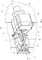
Fig. 1 is an axonometric view of a piece of furniture according to the invention, comprising a locking/unlocking apparatus in open position; -
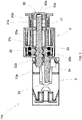
Fig. 2 is a sectional view of the locking/unlocking apparatus along the plane II-II ofFig. 1 ; -
Fig. 3 is a side view of the locking/unlocking apparatus ofFig. 1 ; -
Fig. 4 is the same asFig. 1 , except for it shows the locking/unlocking apparatus in closed position; -
Fig. 5 is a sectional view of the locking/unlocking apparatus along the plane V-V ofFig. 4 ; -
Fig. 6 is a side view of the locking/unlocking apparatus ofFig. 4 ; -
Fig. 7 is an axonometric view of the interior of the piece of furniture ofFig. 1 , wherein the means of the drawer are visible. - With reference to
Figs. 1 ,4 and7 , a piece of furniture according to the invention is disclosed, which is generally indicated with reference numeral (7). - The piece of furniture (7) comprises a parallelepiped frame (71) and one or more drawers (70) that are slidingly mounted relative to the frame (71).
- The piece of furniture (7) comprises a locking/unlocking apparatus (100) used to lock/unlock the drawer (70) of the piece of furniture (7).
- The locking/unlocking apparatus (100) comprises a bar (1) that is mounted with possibility of vertically sliding on the frame (71) of the piece of furniture (7). Advantageously, the bar (1) is slidingly mounted on one side of the frame (71) of the piece of furniture (7).
- The bar (1) has a longitudinal vertical axis. The bar (1) comprises a tooth (11) that projects from the bar (1) towards the interior of the piece of furniture (7). Advantageously, the tooth (11) has a cylindrical shape with a horizontal axis.
- As shown in
Fig. 7 , the bar (1) comprises additional teeth (11a) that project towards the interior of the piece of furniture (7). The piece of furniture (7) comprises means (M) for locking one drawer (70) or multiple drawers (70) simultaneously. With reference toFig. 7 , the means (M) comprise a plate (M1) connected to the drawer (70). The plate (M1) comprises a hook (M3) that projects from the back of the plate (M1). The hook (M3), which is shaped like a hook, defines a housing (M2) that receives the additional teeth (11a) of the bar (1) when the bar (1) is moved upwards, in such way to prevent the drawer (70) from being opened. - It must be noted that the means (M) are of known type and can have different shapes and/or can be disposed in a different position compared to
Fig. 7 . For example, the means (M) can be disposed in lateral position on the side of the drawer (70). - With reference to
Figs. 1 to 6 , the locking/unlocking apparatus (100) comprises moving means (3) for moving the bar (1). Said moving means (3) comprise a parallelepiped frame (33) that is fixed to the piece of furniture (7). Advantageously, the frame (33) of the moving means (3) is fixed to the drawer (70) and is disposed partially inside the piece of furniture (7) and partially outside the piece of furniture (7). With reference toFigs. 2 and5 , the frame (33) of the moving means (3) is internally empty and comprises a first compartment (33a) and a second compartment (33b) in communication with the first compartment (33a). - With reference to
Figs. 1 to 6 , the locking/unlocking apparatus (100) comprises a button (30) disposed outside the piece of furniture (7). The button (30) comprises a fixed element (30b) that is screwed to the frame (33) of the moving means (3), and a mobile element (30c) that is slidingly mounted in the fixed element (30b). The mobile element (30c) of the button (30) comprises a compartment in communication with the first compartment (33a) of the frame (33) of the moving means (3). The mobile element (30c) of the button (30) comprises a threaded housing (30a) disposed inside the compartment of the mobile element (30c). - With reference to
Figs. 2 to 4 , the locking/unlocking apparatus (100) comprises a ring (32) that is slidingly mounted in the second compartment (33b) of the frame (33) of the moving means (3) and comprises a central threaded hole (32b). - Moreover, the locking/unlocking apparatus (100) comprises a threaded pin (31) that is revolvingly and slidingly mounted in the frame (33) of the moving means (3). In particular, the threaded pin (31) comprises a first threaded ending section (31a) screwed into the threaded housing (30a) of the button (30), a second threaded ending section (31b) screwed into the threaded hole (32b) of the ring (32), and a non-threaded body (31c) disposed between the two threaded ending sections (31a, 31b). Otherwise said, the first threaded ending section (31a) of the threaded pin (31) is disposed at least partially inside the compartment of the mobile element (30c) of the button (30), the central body (31c) is disposed inside the first compartment (33a) of the frame (33) of the moving means (3) and the second ending section (31b) is disposed at least partially inside the second compartment (33b) of the frame (33) of the moving means (3).
- The thread of the threaded ending section (31a) of the threaded pin (31) has a lower pitch than the thread of the second threaded ending section (31b) of the threaded pin (31). The provision of two threads with different pitch permits to define the rotation degrees of the ring (32) at every travel of the button (30). As a matter of fact, the thread of the first threaded ending section (31a) permits to adjust the displacement of the threaded pin (31) according to the travel of the button (30) and the thread of the second threaded ending section (31b) permits to adjust the rotation of the ring (32) according to the displacement of the threaded pin (31).
- The locking/unlocking apparatus (100) comprises a peg (34) that projects from the frame (33) of the moving means (3) and is joined to the ring (32). In particular, the peg (34) is peripherally connected to the ring (32), in such way to move along a circular trajectory with the center of the ring (32) as center. The peg (34) cooperates with the tooth (11) of the bar (1) to move the tooth (11) of the bar (1).
- With reference to
Figs. 1 ,2 ,4 and5 , the locking/unlocking apparatus (100) advantageously comprises motion transmission means (2) that are slidingly mounted on the piece of furniture (7) and connected to the bar (1) and to the moving means (3) to transmit the motion from the moving means (3) to the bar (1). - The motion transmission means (2) comprise a first surface (20) cooperating with the tooth (11) of the bar (1). More precisely, the motion transmission means (2) comprise an upper surface that coincides with the first surface (20) of the motion transmission means (2).
- Alternatively, as shown in
Fig. 7 , the motion transmission means (2) comprise a lateral niche defined by an internal surface. The tooth (11) of the bar (1) is inserted in the lateral niche. The internal surface that defines the lateral niche coincides with the first surface (20) of the motion transmission means (2). - The motion transmission means (2) comprise a second surface (21) that cooperates with the peg (34) of the moving means (3). More precisely, the motion transmission means (2) comprise a seat (22) defined by an internal surface. The peg (34) of the moving means (3) is inserted in the seat (22). The internal surface that defines the seat (22) coincides with the second surface (21) of the motion transmission means (2).
- The seat (22) of the motion transmission means (2) is shaped as a semicircle with lower radius of curvature than the circular trajectory of the peg (34). In view of the above, when moving, the peg (34) intercepts the internal wall of the seat (22) and moves the motion transmission means (2) either upwards or downwards. Because of the semicircular shape of the seat (22), a movement of the peg (34) inside the seat (22) determines a movement of the motion transmission means (2) exclusively in vertical direction, without causing the horizontal displacement of said motion transmission means (2).
- The piece of furniture (7) comprises vertical guides (4) that are fixed to a side of the frame (71) of the piece of furniture. The motion transmission means (2) are slidingly mounted in the guides (4). Advantageously, the guides (4) have a lower wall that supports the motion transmission means (2) when said motion transmission means (2) are in a lowered position.
- In order to lock the drawer (70) to the frame (71) of the piece of furniture (7), the mobile element (30c) of the button (30) of the moving means (3) must be pressed. A sliding movement of the mobile element (30c) of the button (30) determines a rotation of the threaded pin (31) in the threaded housing (30a) of the mobile element (30c). The threaded pin (31) is screwed in the threaded housing (30a) of the button (30) and is simultaneously screwed in the central threaded hole (32b) of the ring (32), causing a rotation of approximately 180° of the ring (32) in a closing direction. The peg (34) is moved along the circular trajectory, going from a lower dead point, which is shown in
Fig. 1 , to an upper dead point, which is shown inFig. 4 . The peg (34) moves the motion transmission means (2) upwards. Consequently, the bar (1) slides upwards and cooperates with the means (M) to lock the drawer (70). So the locking/unlocking apparatus (100) is in closing position. - In order to open the drawer (70), the mobile element (30c) of the button (30) must be pressed again. The threaded pin (31) is unscrewed from the threaded housing (30a) of the button (30) and simultaneously from the central threaded hole (32b) of the ring (32), causing a rotation of approximately 180° of the ring (32) in an opening direction, which is opposite to the closing direction. The peg (34) is moved along the circular trajectory, going from the upper dead point, which is shown in
Fig. 4 , to the lower dead point, which is shown inFig. 1 . The motion transmission means (2) are moved downwards by gravity. Also the tooth (11) is moved downwards by gravity, if the tooth (11) is disposed on the upper surface of the motion transmission means (2). Alternatively, the tooth (11) is pushed downwards by the motion transmission means (2), if the tooth (11) is disposed in the lateral niche of the motion transmission means (2). Consequently, the bar (1) slides downwards, being released from the means (M) and permitting the opening of the drawer. So the locking/unlocking apparatus (100) is in opening position. - Although this description refers to a piece of furniture with drawers, the piece of furniture may comprise one or more door panels. In such a case, the locking/unlocking apparatus permits to lock/unlock one door panel of the piece of furniture or multiple door panels of the piece of furniture at the same time.
- Although it is not shown in the attached figures, the locking/unlocking apparatus (100) may not be provided with the motion transmission means (2). In such a case, the peg (34) of the moving means (3) directly acts on the tooth (11) of the bar (1), in such way to move the bar (1) upwards or downwards.
- Although it is not shown in the attached figures, alternatively, the moving means (3) may be disposed on the side of the frame (71) of the piece of furniture, in adjacent position to the motion transmission means (2). In such a case, the peg (34) has an "L"-shape.
Claims (9)
- Locking/unlocking apparatus (100) to lock/unlock a door panel or a drawer (70) of a piece of furniture (7); said locking/unlocking apparatus (100) comprising:- a bar (1) suitable for being slidingly mounted on a piece of furniture (7); said bar (1) being configured in such way to cooperate with means (M) of the piece of furniture (7) to lock the door panel or the drawer (70) to a frame (71) of the piece of furniture (7);- moving means (3) to move the bar (1); said moving means (3) comprising a frame (33) suitable for being fixed to the piece of furniture (7);characterized in that
said bar (1) comprises a tooth (11) that projects from said bar (1), and
said moving means (3) also comprise:- a button (30) connected to the frame (33) and disposed outside the piece of furniture (7); said button (30) comprising a threaded housing (30a);- a ring (32) revolvingly mounted in the frame (33) and comprising a threaded central hole (32b);- a threaded pin (31) revolvingly and slidingly mounted in the frame (33); said threaded pin (31) having a first threaded ending section (31a) screwed into the threaded housing (30a) of the button (30) and a second threaded ending section (31b) screwed into the threaded hole (32b) of the ring (32);- a peg (34) joined to said ring (32) and projecting from said frame (33); said peg (34) being intended to cooperate with said tooth (11) of the bar (1) to move said tooth (11) of the bar (1). - The locking/unlocking apparatus (100) of claim 1, wherein the thread of the threaded ending section (31a) of the threaded pin (31) has a lower pitch than the thread of the second threaded ending section (31b) of the threaded pin (31).
- The locking/unlocking apparatus (100) of any one of the preceding claims, comprising motion transmission means (2) slidingly mounted on the piece of furniture (7) and connected to the bar (1) and to the moving means (3) to transmit the motion from the moving means (3) to the bar (1); said motion transmission means (2) comprising:- a first surface (20) cooperating with the tooth (11) of the locking bar (1);- a second surface (21) cooperating with the peg (34) of the moving means (3).
- The locking/unlocking apparatus (100) of claim 3, wherein said motion transmission means (2) comprise a seat (22) defined by an internal surface and housing said peg (34) of the moving means (3); said internal surface that defines the seat (22) coinciding with the second surface (21) of the motion transmission means (2).
- The locking/unlocking assembly (100) of claim 4, wherein said seat (22) has a semicircular shape.
- The locking/unlocking assembly (100) of any one of claims 3 to 5, wherein said motion transmission means (2) comprise an upper surface that coincides with the first surface (20) of the motion transmission means (2).
- The locking/unlocking assembly (100) of any one of claims 3 to 5, wherein said motion transmission means (2) comprise a lateral niche defined by an internal surface and housing said tooth (11) of the bar (1); said internal surface that defines the lateral niche coinciding with the first surface (20) of the motion transmission means (2).
- The locking/unlocking apparatus (100) of any one of claims 2 to 7, comprising guides (4) fixed to the piece of furniture (7); said motion transmission means (2) being slidingly mounted in said guides (4).
- Piece of furniture (7) comprising:- a frame (71);- a door panel or a drawer (70) connected to said frame (71);- means (M) connected to said door panel or drawer (70) of the piece of furniture (7);- a locking/unlocking apparatus (100) according to any one of the preceding claims, which is connected to said frame (71) and cooperates with said means (M) to lock the door panel or the drawer (70) to the frame (71).
Applications Claiming Priority (1)
| Application Number | Priority Date | Filing Date | Title |
|---|---|---|---|
| IT102017000020210A IT201700020210A1 (en) | 2017-02-22 | 2017-02-22 | LOCKING / UNLOCKING GROUP FOR A FURNITURE. |
Publications (2)
| Publication Number | Publication Date |
|---|---|
| EP3366874A1 EP3366874A1 (en) | 2018-08-29 |
| EP3366874B1 true EP3366874B1 (en) | 2019-03-27 |
Family
ID=59253899
Family Applications (1)
| Application Number | Title | Priority Date | Filing Date |
|---|---|---|---|
| EP18157238.9A Active EP3366874B1 (en) | 2017-02-22 | 2018-02-16 | Locking/unlocking apparatus for a piece of furniture |
Country Status (2)
| Country | Link |
|---|---|
| EP (1) | EP3366874B1 (en) |
| IT (1) | IT201700020210A1 (en) |
Family Cites Families (2)
| Publication number | Priority date | Publication date | Assignee | Title |
|---|---|---|---|---|
| US5358322A (en) * | 1992-12-16 | 1994-10-25 | Krueger International, Inc. | Drawer locking system |
| DE102013109493A1 (en) * | 2013-08-30 | 2015-03-05 | Karl Simon Gmbh & Co. Kg | Hardware for a drawer module of a mobile vehicle |
-
2017
- 2017-02-22 IT IT102017000020210A patent/IT201700020210A1/en unknown
-
2018
- 2018-02-16 EP EP18157238.9A patent/EP3366874B1/en active Active
Non-Patent Citations (1)
| Title |
|---|
| None * |
Also Published As
| Publication number | Publication date |
|---|---|
| EP3366874A1 (en) | 2018-08-29 |
| IT201700020210A1 (en) | 2018-08-22 |
Similar Documents
| Publication | Publication Date | Title |
|---|---|---|
| CN101705758B (en) | Free-swing handle structure for safe | |
| US9074391B2 (en) | Panic lock | |
| CA2337989C (en) | Sliding element unit | |
| US20160194904A1 (en) | Locking device for two-way travel drawer | |
| EP1106761B1 (en) | Safety lock for doors | |
| WO2016128715A1 (en) | Locking apparatus for a handle spindle and method for use thereof | |
| EP3366874A1 (en) | Locking/unlocking apparatus for a piece of furniture | |
| US8348357B2 (en) | Drawer assembly locking mechanism | |
| KR102347158B1 (en) | Safety locking device for door handle | |
| RU2632397C2 (en) | Mobile part for directed movement of furniture part in direction of movement and furniture fittings | |
| CN109025655A (en) | Sliding door safety cabinet | |
| KR200458415Y1 (en) | Locker key ring lock | |
| KR101119837B1 (en) | Safety locker to block safety bar interlocking of safety door | |
| EP0777030A1 (en) | Sliding door and handling jamb therefor | |
| KR20150112458A (en) | Safty device for door | |
| KR101057529B1 (en) | Two Point Type Door Locking Device | |
| KR20110119037A (en) | Home Bar Lock | |
| KR101020614B1 (en) | Safety bar and door lock on tempered glass safety door | |
| KR102627362B1 (en) | Push button type door-lock apparatus for sliding door | |
| KR101115424B1 (en) | A button type-locking devise for window | |
| EP3845841B1 (en) | A refrigerator comprising a door | |
| KR101202477B1 (en) | Locking Device For Filebox With Several Drawers | |
| WO2014131075A1 (en) | Folding door latch | |
| JP2015137490A (en) | Dual action door comprising inter-connected opening/closing device and inter-connected opening/closing device for door | |
| KR20170067113A (en) | Locking device of sliding door |
Legal Events
| Date | Code | Title | Description |
|---|---|---|---|
| PUAI | Public reference made under article 153(3) epc to a published international application that has entered the european phase |
Free format text: ORIGINAL CODE: 0009012 |
|
| STAA | Information on the status of an ep patent application or granted ep patent |
Free format text: STATUS: THE APPLICATION HAS BEEN PUBLISHED |
|
| AK | Designated contracting states |
Kind code of ref document: A1 Designated state(s): AL AT BE BG CH CY CZ DE DK EE ES FI FR GB GR HR HU IE IS IT LI LT LU LV MC MK MT NL NO PL PT RO RS SE SI SK SM TR |
|
| AX | Request for extension of the european patent |
Extension state: BA ME |
|
| STAA | Information on the status of an ep patent application or granted ep patent |
Free format text: STATUS: REQUEST FOR EXAMINATION WAS MADE |
|
| 17P | Request for examination filed |
Effective date: 20181017 |
|
| RBV | Designated contracting states (corrected) |
Designated state(s): AL AT BE BG CH CY CZ DE DK EE ES FI FR GB GR HR HU IE IS IT LI LT LU LV MC MK MT NL NO PL PT RO RS SE SI SK SM TR |
|
| GRAP | Despatch of communication of intention to grant a patent |
Free format text: ORIGINAL CODE: EPIDOSNIGR1 |
|
| STAA | Information on the status of an ep patent application or granted ep patent |
Free format text: STATUS: GRANT OF PATENT IS INTENDED |
|
| INTG | Intention to grant announced |
Effective date: 20181217 |
|
| GRAS | Grant fee paid |
Free format text: ORIGINAL CODE: EPIDOSNIGR3 |
|
| GRAA | (expected) grant |
Free format text: ORIGINAL CODE: 0009210 |
|
| STAA | Information on the status of an ep patent application or granted ep patent |
Free format text: STATUS: THE PATENT HAS BEEN GRANTED |
|
| AK | Designated contracting states |
Kind code of ref document: B1 Designated state(s): AL AT BE BG CH CY CZ DE DK EE ES FI FR GB GR HR HU IE IS IT LI LT LU LV MC MK MT NL NO PL PT RO RS SE SI SK SM TR |
|
| REG | Reference to a national code |
Ref country code: GB Ref legal event code: FG4D |
|
| REG | Reference to a national code |
Ref country code: CH Ref legal event code: EP |
|
| REG | Reference to a national code |
Ref country code: AT Ref legal event code: REF Ref document number: 1113281 Country of ref document: AT Kind code of ref document: T Effective date: 20190415 |
|
| REG | Reference to a national code |
Ref country code: IE Ref legal event code: FG4D |
|
| REG | Reference to a national code |
Ref country code: DE Ref legal event code: R096 Ref document number: 602018000024 Country of ref document: DE |
|
| PG25 | Lapsed in a contracting state [announced via postgrant information from national office to epo] |
Ref country code: SE Free format text: LAPSE BECAUSE OF FAILURE TO SUBMIT A TRANSLATION OF THE DESCRIPTION OR TO PAY THE FEE WITHIN THE PRESCRIBED TIME-LIMIT Effective date: 20190327 Ref country code: FI Free format text: LAPSE BECAUSE OF FAILURE TO SUBMIT A TRANSLATION OF THE DESCRIPTION OR TO PAY THE FEE WITHIN THE PRESCRIBED TIME-LIMIT Effective date: 20190327 Ref country code: LT Free format text: LAPSE BECAUSE OF FAILURE TO SUBMIT A TRANSLATION OF THE DESCRIPTION OR TO PAY THE FEE WITHIN THE PRESCRIBED TIME-LIMIT Effective date: 20190327 Ref country code: NO Free format text: LAPSE BECAUSE OF FAILURE TO SUBMIT A TRANSLATION OF THE DESCRIPTION OR TO PAY THE FEE WITHIN THE PRESCRIBED TIME-LIMIT Effective date: 20190627 |
|
| REG | Reference to a national code |
Ref country code: NL Ref legal event code: MP Effective date: 20190327 |
|
| PG25 | Lapsed in a contracting state [announced via postgrant information from national office to epo] |
Ref country code: NL Free format text: LAPSE BECAUSE OF FAILURE TO SUBMIT A TRANSLATION OF THE DESCRIPTION OR TO PAY THE FEE WITHIN THE PRESCRIBED TIME-LIMIT Effective date: 20190327 Ref country code: GR Free format text: LAPSE BECAUSE OF FAILURE TO SUBMIT A TRANSLATION OF THE DESCRIPTION OR TO PAY THE FEE WITHIN THE PRESCRIBED TIME-LIMIT Effective date: 20190628 Ref country code: HR Free format text: LAPSE BECAUSE OF FAILURE TO SUBMIT A TRANSLATION OF THE DESCRIPTION OR TO PAY THE FEE WITHIN THE PRESCRIBED TIME-LIMIT Effective date: 20190327 Ref country code: BG Free format text: LAPSE BECAUSE OF FAILURE TO SUBMIT A TRANSLATION OF THE DESCRIPTION OR TO PAY THE FEE WITHIN THE PRESCRIBED TIME-LIMIT Effective date: 20190627 Ref country code: RS Free format text: LAPSE BECAUSE OF FAILURE TO SUBMIT A TRANSLATION OF THE DESCRIPTION OR TO PAY THE FEE WITHIN THE PRESCRIBED TIME-LIMIT Effective date: 20190327 Ref country code: LV Free format text: LAPSE BECAUSE OF FAILURE TO SUBMIT A TRANSLATION OF THE DESCRIPTION OR TO PAY THE FEE WITHIN THE PRESCRIBED TIME-LIMIT Effective date: 20190327 |
|
| REG | Reference to a national code |
Ref country code: AT Ref legal event code: MK05 Ref document number: 1113281 Country of ref document: AT Kind code of ref document: T Effective date: 20190327 |
|
| PG25 | Lapsed in a contracting state [announced via postgrant information from national office to epo] |
Ref country code: ES Free format text: LAPSE BECAUSE OF FAILURE TO SUBMIT A TRANSLATION OF THE DESCRIPTION OR TO PAY THE FEE WITHIN THE PRESCRIBED TIME-LIMIT Effective date: 20190327 Ref country code: RO Free format text: LAPSE BECAUSE OF FAILURE TO SUBMIT A TRANSLATION OF THE DESCRIPTION OR TO PAY THE FEE WITHIN THE PRESCRIBED TIME-LIMIT Effective date: 20190327 Ref country code: AL Free format text: LAPSE BECAUSE OF FAILURE TO SUBMIT A TRANSLATION OF THE DESCRIPTION OR TO PAY THE FEE WITHIN THE PRESCRIBED TIME-LIMIT Effective date: 20190327 Ref country code: EE Free format text: LAPSE BECAUSE OF FAILURE TO SUBMIT A TRANSLATION OF THE DESCRIPTION OR TO PAY THE FEE WITHIN THE PRESCRIBED TIME-LIMIT Effective date: 20190327 Ref country code: SK Free format text: LAPSE BECAUSE OF FAILURE TO SUBMIT A TRANSLATION OF THE DESCRIPTION OR TO PAY THE FEE WITHIN THE PRESCRIBED TIME-LIMIT Effective date: 20190327 Ref country code: PT Free format text: LAPSE BECAUSE OF FAILURE TO SUBMIT A TRANSLATION OF THE DESCRIPTION OR TO PAY THE FEE WITHIN THE PRESCRIBED TIME-LIMIT Effective date: 20190727 Ref country code: CZ Free format text: LAPSE BECAUSE OF FAILURE TO SUBMIT A TRANSLATION OF THE DESCRIPTION OR TO PAY THE FEE WITHIN THE PRESCRIBED TIME-LIMIT Effective date: 20190327 |
|
| PG25 | Lapsed in a contracting state [announced via postgrant information from national office to epo] |
Ref country code: PL Free format text: LAPSE BECAUSE OF FAILURE TO SUBMIT A TRANSLATION OF THE DESCRIPTION OR TO PAY THE FEE WITHIN THE PRESCRIBED TIME-LIMIT Effective date: 20190327 Ref country code: SM Free format text: LAPSE BECAUSE OF FAILURE TO SUBMIT A TRANSLATION OF THE DESCRIPTION OR TO PAY THE FEE WITHIN THE PRESCRIBED TIME-LIMIT Effective date: 20190327 |
|
| PG25 | Lapsed in a contracting state [announced via postgrant information from national office to epo] |
Ref country code: IS Free format text: LAPSE BECAUSE OF FAILURE TO SUBMIT A TRANSLATION OF THE DESCRIPTION OR TO PAY THE FEE WITHIN THE PRESCRIBED TIME-LIMIT Effective date: 20190727 Ref country code: AT Free format text: LAPSE BECAUSE OF FAILURE TO SUBMIT A TRANSLATION OF THE DESCRIPTION OR TO PAY THE FEE WITHIN THE PRESCRIBED TIME-LIMIT Effective date: 20190327 |
|
| REG | Reference to a national code |
Ref country code: DE Ref legal event code: R097 Ref document number: 602018000024 Country of ref document: DE |
|
| PG25 | Lapsed in a contracting state [announced via postgrant information from national office to epo] |
Ref country code: DK Free format text: LAPSE BECAUSE OF FAILURE TO SUBMIT A TRANSLATION OF THE DESCRIPTION OR TO PAY THE FEE WITHIN THE PRESCRIBED TIME-LIMIT Effective date: 20190327 |
|
| PLBE | No opposition filed within time limit |
Free format text: ORIGINAL CODE: 0009261 |
|
| STAA | Information on the status of an ep patent application or granted ep patent |
Free format text: STATUS: NO OPPOSITION FILED WITHIN TIME LIMIT |
|
| 26N | No opposition filed |
Effective date: 20200103 |
|
| PG25 | Lapsed in a contracting state [announced via postgrant information from national office to epo] |
Ref country code: TR Free format text: LAPSE BECAUSE OF FAILURE TO SUBMIT A TRANSLATION OF THE DESCRIPTION OR TO PAY THE FEE WITHIN THE PRESCRIBED TIME-LIMIT Effective date: 20190327 |
|
| REG | Reference to a national code |
Ref country code: BE Ref legal event code: MM Effective date: 20200229 |
|
| PG25 | Lapsed in a contracting state [announced via postgrant information from national office to epo] |
Ref country code: LU Free format text: LAPSE BECAUSE OF NON-PAYMENT OF DUE FEES Effective date: 20200216 Ref country code: MC Free format text: LAPSE BECAUSE OF FAILURE TO SUBMIT A TRANSLATION OF THE DESCRIPTION OR TO PAY THE FEE WITHIN THE PRESCRIBED TIME-LIMIT Effective date: 20190327 |
|
| PG25 | Lapsed in a contracting state [announced via postgrant information from national office to epo] |
Ref country code: IE Free format text: LAPSE BECAUSE OF NON-PAYMENT OF DUE FEES Effective date: 20200216 |
|
| PG25 | Lapsed in a contracting state [announced via postgrant information from national office to epo] |
Ref country code: BE Free format text: LAPSE BECAUSE OF NON-PAYMENT OF DUE FEES Effective date: 20200229 |
|
| PG25 | Lapsed in a contracting state [announced via postgrant information from national office to epo] |
Ref country code: LI Free format text: LAPSE BECAUSE OF NON-PAYMENT OF DUE FEES Effective date: 20210228 Ref country code: CH Free format text: LAPSE BECAUSE OF NON-PAYMENT OF DUE FEES Effective date: 20210228 |
|
| PG25 | Lapsed in a contracting state [announced via postgrant information from national office to epo] |
Ref country code: MT Free format text: LAPSE BECAUSE OF FAILURE TO SUBMIT A TRANSLATION OF THE DESCRIPTION OR TO PAY THE FEE WITHIN THE PRESCRIBED TIME-LIMIT Effective date: 20190327 Ref country code: CY Free format text: LAPSE BECAUSE OF FAILURE TO SUBMIT A TRANSLATION OF THE DESCRIPTION OR TO PAY THE FEE WITHIN THE PRESCRIBED TIME-LIMIT Effective date: 20190327 |
|
| PG25 | Lapsed in a contracting state [announced via postgrant information from national office to epo] |
Ref country code: MK Free format text: LAPSE BECAUSE OF FAILURE TO SUBMIT A TRANSLATION OF THE DESCRIPTION OR TO PAY THE FEE WITHIN THE PRESCRIBED TIME-LIMIT Effective date: 20190327 |
|
| P01 | Opt-out of the competence of the unified patent court (upc) registered |
Effective date: 20230515 |
|
| PG25 | Lapsed in a contracting state [announced via postgrant information from national office to epo] |
Ref country code: SI Free format text: LAPSE BECAUSE OF FAILURE TO SUBMIT A TRANSLATION OF THE DESCRIPTION OR TO PAY THE FEE WITHIN THE PRESCRIBED TIME-LIMIT Effective date: 20190327 |
|
| PGFP | Annual fee paid to national office [announced via postgrant information from national office to epo] |
Ref country code: GB Payment date: 20260122 Year of fee payment: 9 |
|
| PGFP | Annual fee paid to national office [announced via postgrant information from national office to epo] |
Ref country code: DE Payment date: 20260220 Year of fee payment: 9 |
|
| PGFP | Annual fee paid to national office [announced via postgrant information from national office to epo] |
Ref country code: IT Payment date: 20260116 Year of fee payment: 9 |
|
| PGFP | Annual fee paid to national office [announced via postgrant information from national office to epo] |
Ref country code: FR Payment date: 20260227 Year of fee payment: 9 |