EP3366846A1 - Work vehicle with remote brake release - Google Patents
Work vehicle with remote brake release Download PDFInfo
- Publication number
- EP3366846A1 EP3366846A1 EP18158629.8A EP18158629A EP3366846A1 EP 3366846 A1 EP3366846 A1 EP 3366846A1 EP 18158629 A EP18158629 A EP 18158629A EP 3366846 A1 EP3366846 A1 EP 3366846A1
- Authority
- EP
- European Patent Office
- Prior art keywords
- release valve
- primary
- braking
- valve
- braking system
- Prior art date
- Legal status (The legal status is an assumption and is not a legal conclusion. Google has not performed a legal analysis and makes no representation as to the accuracy of the status listed.)
- Withdrawn
Links
Images

Classifications
-
- B—PERFORMING OPERATIONS; TRANSPORTING
- B60—VEHICLES IN GENERAL
- B60T—VEHICLE BRAKE CONTROL SYSTEMS OR PARTS THEREOF; BRAKE CONTROL SYSTEMS OR PARTS THEREOF, IN GENERAL; ARRANGEMENT OF BRAKING ELEMENTS ON VEHICLES IN GENERAL; PORTABLE DEVICES FOR PREVENTING UNWANTED MOVEMENT OF VEHICLES; VEHICLE MODIFICATIONS TO FACILITATE COOLING OF BRAKES
- B60T15/00—Construction arrangement, or operation of valves incorporated in power brake systems and not covered by groups B60T11/00 or B60T13/00
- B60T15/02—Application and release valves
- B60T15/36—Other control devices or valves characterised by definite functions
- B60T15/48—Other control devices or valves characterised by definite functions for filling reservoirs
- B60T15/50—Other control devices or valves characterised by definite functions for filling reservoirs with means for limiting or relieving pressure in reservoirs
-
- B—PERFORMING OPERATIONS; TRANSPORTING
- B60—VEHICLES IN GENERAL
- B60T—VEHICLE BRAKE CONTROL SYSTEMS OR PARTS THEREOF; BRAKE CONTROL SYSTEMS OR PARTS THEREOF, IN GENERAL; ARRANGEMENT OF BRAKING ELEMENTS ON VEHICLES IN GENERAL; PORTABLE DEVICES FOR PREVENTING UNWANTED MOVEMENT OF VEHICLES; VEHICLE MODIFICATIONS TO FACILITATE COOLING OF BRAKES
- B60T1/00—Arrangements of braking elements, i.e. of those parts where braking effect occurs specially for vehicles
- B60T1/02—Arrangements of braking elements, i.e. of those parts where braking effect occurs specially for vehicles acting by retarding wheels
- B60T1/08—Arrangements of braking elements, i.e. of those parts where braking effect occurs specially for vehicles acting by retarding wheels using fluid or powdered medium
- B60T1/093—Arrangements of braking elements, i.e. of those parts where braking effect occurs specially for vehicles acting by retarding wheels using fluid or powdered medium in hydrostatic, i.e. positive displacement, retarders
-
- B—PERFORMING OPERATIONS; TRANSPORTING
- B60—VEHICLES IN GENERAL
- B60T—VEHICLE BRAKE CONTROL SYSTEMS OR PARTS THEREOF; BRAKE CONTROL SYSTEMS OR PARTS THEREOF, IN GENERAL; ARRANGEMENT OF BRAKING ELEMENTS ON VEHICLES IN GENERAL; PORTABLE DEVICES FOR PREVENTING UNWANTED MOVEMENT OF VEHICLES; VEHICLE MODIFICATIONS TO FACILITATE COOLING OF BRAKES
- B60T10/00—Control or regulation for continuous braking making use of fluid or powdered medium, e.g. for use when descending a long slope
- B60T10/04—Control or regulation for continuous braking making use of fluid or powdered medium, e.g. for use when descending a long slope with hydrostatic brake
-
- B—PERFORMING OPERATIONS; TRANSPORTING
- B60—VEHICLES IN GENERAL
- B60T—VEHICLE BRAKE CONTROL SYSTEMS OR PARTS THEREOF; BRAKE CONTROL SYSTEMS OR PARTS THEREOF, IN GENERAL; ARRANGEMENT OF BRAKING ELEMENTS ON VEHICLES IN GENERAL; PORTABLE DEVICES FOR PREVENTING UNWANTED MOVEMENT OF VEHICLES; VEHICLE MODIFICATIONS TO FACILITATE COOLING OF BRAKES
- B60T13/00—Transmitting braking action from initiating means to ultimate brake actuator with power assistance or drive; Brake systems incorporating such transmitting means, e.g. air-pressure brake systems
- B60T13/10—Transmitting braking action from initiating means to ultimate brake actuator with power assistance or drive; Brake systems incorporating such transmitting means, e.g. air-pressure brake systems with fluid assistance, drive, or release
- B60T13/12—Transmitting braking action from initiating means to ultimate brake actuator with power assistance or drive; Brake systems incorporating such transmitting means, e.g. air-pressure brake systems with fluid assistance, drive, or release the fluid being liquid
- B60T13/14—Transmitting braking action from initiating means to ultimate brake actuator with power assistance or drive; Brake systems incorporating such transmitting means, e.g. air-pressure brake systems with fluid assistance, drive, or release the fluid being liquid using accumulators or reservoirs fed by pumps
- B60T13/148—Arrangements for pressure supply
-
- B—PERFORMING OPERATIONS; TRANSPORTING
- B60—VEHICLES IN GENERAL
- B60T—VEHICLE BRAKE CONTROL SYSTEMS OR PARTS THEREOF; BRAKE CONTROL SYSTEMS OR PARTS THEREOF, IN GENERAL; ARRANGEMENT OF BRAKING ELEMENTS ON VEHICLES IN GENERAL; PORTABLE DEVICES FOR PREVENTING UNWANTED MOVEMENT OF VEHICLES; VEHICLE MODIFICATIONS TO FACILITATE COOLING OF BRAKES
- B60T13/00—Transmitting braking action from initiating means to ultimate brake actuator with power assistance or drive; Brake systems incorporating such transmitting means, e.g. air-pressure brake systems
- B60T13/10—Transmitting braking action from initiating means to ultimate brake actuator with power assistance or drive; Brake systems incorporating such transmitting means, e.g. air-pressure brake systems with fluid assistance, drive, or release
- B60T13/12—Transmitting braking action from initiating means to ultimate brake actuator with power assistance or drive; Brake systems incorporating such transmitting means, e.g. air-pressure brake systems with fluid assistance, drive, or release the fluid being liquid
- B60T13/22—Brakes applied by springs or weights and released hydraulically
-
- B—PERFORMING OPERATIONS; TRANSPORTING
- B60—VEHICLES IN GENERAL
- B60T—VEHICLE BRAKE CONTROL SYSTEMS OR PARTS THEREOF; BRAKE CONTROL SYSTEMS OR PARTS THEREOF, IN GENERAL; ARRANGEMENT OF BRAKING ELEMENTS ON VEHICLES IN GENERAL; PORTABLE DEVICES FOR PREVENTING UNWANTED MOVEMENT OF VEHICLES; VEHICLE MODIFICATIONS TO FACILITATE COOLING OF BRAKES
- B60T13/00—Transmitting braking action from initiating means to ultimate brake actuator with power assistance or drive; Brake systems incorporating such transmitting means, e.g. air-pressure brake systems
- B60T13/10—Transmitting braking action from initiating means to ultimate brake actuator with power assistance or drive; Brake systems incorporating such transmitting means, e.g. air-pressure brake systems with fluid assistance, drive, or release
- B60T13/66—Electrical control in fluid-pressure brake systems
- B60T13/662—Electrical control in fluid-pressure brake systems characterised by specified functions of the control system components
-
- B—PERFORMING OPERATIONS; TRANSPORTING
- B60—VEHICLES IN GENERAL
- B60T—VEHICLE BRAKE CONTROL SYSTEMS OR PARTS THEREOF; BRAKE CONTROL SYSTEMS OR PARTS THEREOF, IN GENERAL; ARRANGEMENT OF BRAKING ELEMENTS ON VEHICLES IN GENERAL; PORTABLE DEVICES FOR PREVENTING UNWANTED MOVEMENT OF VEHICLES; VEHICLE MODIFICATIONS TO FACILITATE COOLING OF BRAKES
- B60T13/00—Transmitting braking action from initiating means to ultimate brake actuator with power assistance or drive; Brake systems incorporating such transmitting means, e.g. air-pressure brake systems
- B60T13/10—Transmitting braking action from initiating means to ultimate brake actuator with power assistance or drive; Brake systems incorporating such transmitting means, e.g. air-pressure brake systems with fluid assistance, drive, or release
- B60T13/66—Electrical control in fluid-pressure brake systems
- B60T13/68—Electrical control in fluid-pressure brake systems by electrically-controlled valves
- B60T13/686—Electrical control in fluid-pressure brake systems by electrically-controlled valves in hydraulic systems or parts thereof
-
- B—PERFORMING OPERATIONS; TRANSPORTING
- B60—VEHICLES IN GENERAL
- B60T—VEHICLE BRAKE CONTROL SYSTEMS OR PARTS THEREOF; BRAKE CONTROL SYSTEMS OR PARTS THEREOF, IN GENERAL; ARRANGEMENT OF BRAKING ELEMENTS ON VEHICLES IN GENERAL; PORTABLE DEVICES FOR PREVENTING UNWANTED MOVEMENT OF VEHICLES; VEHICLE MODIFICATIONS TO FACILITATE COOLING OF BRAKES
- B60T15/00—Construction arrangement, or operation of valves incorporated in power brake systems and not covered by groups B60T11/00 or B60T13/00
- B60T15/02—Application and release valves
- B60T15/025—Electrically controlled valves
- B60T15/028—Electrically controlled valves in hydraulic systems
-
- B—PERFORMING OPERATIONS; TRANSPORTING
- B62—LAND VEHICLES FOR TRAVELLING OTHERWISE THAN ON RAILS
- B62D—MOTOR VEHICLES; TRAILERS
- B62D33/00—Superstructures for load-carrying vehicles
- B62D33/077—Superstructures for load-carrying vehicles characterised by the connection of the superstructure to the vehicle frame
-
- E—FIXED CONSTRUCTIONS
- E02—HYDRAULIC ENGINEERING; FOUNDATIONS; SOIL SHIFTING
- E02F—DREDGING; SOIL-SHIFTING
- E02F9/00—Component parts of dredgers or soil-shifting machines, not restricted to one of the kinds covered by groups E02F3/00 - E02F7/00
- E02F9/20—Drives; Control devices
- E02F9/2058—Electric or electro-mechanical or mechanical control devices of vehicle sub-units
- E02F9/2083—Control of vehicle braking systems
-
- E—FIXED CONSTRUCTIONS
- E02—HYDRAULIC ENGINEERING; FOUNDATIONS; SOIL SHIFTING
- E02F—DREDGING; SOIL-SHIFTING
- E02F9/00—Component parts of dredgers or soil-shifting machines, not restricted to one of the kinds covered by groups E02F3/00 - E02F7/00
- E02F9/20—Drives; Control devices
- E02F9/22—Hydraulic or pneumatic drives
- E02F9/226—Safety arrangements, e.g. hydraulic driven fans, preventing cavitation, leakage, overheating
-
- F—MECHANICAL ENGINEERING; LIGHTING; HEATING; WEAPONS; BLASTING
- F16—ENGINEERING ELEMENTS AND UNITS; GENERAL MEASURES FOR PRODUCING AND MAINTAINING EFFECTIVE FUNCTIONING OF MACHINES OR INSTALLATIONS; THERMAL INSULATION IN GENERAL
- F16D—COUPLINGS FOR TRANSMITTING ROTATION; CLUTCHES; BRAKES
- F16D57/00—Liquid-resistance brakes; Brakes using the internal friction of fluids or fluid-like media, e.g. powders
- F16D57/06—Liquid-resistance brakes; Brakes using the internal friction of fluids or fluid-like media, e.g. powders comprising a pump circulating fluid, braking being effected by throttling of the circulation
-
- B—PERFORMING OPERATIONS; TRANSPORTING
- B60—VEHICLES IN GENERAL
- B60T—VEHICLE BRAKE CONTROL SYSTEMS OR PARTS THEREOF; BRAKE CONTROL SYSTEMS OR PARTS THEREOF, IN GENERAL; ARRANGEMENT OF BRAKING ELEMENTS ON VEHICLES IN GENERAL; PORTABLE DEVICES FOR PREVENTING UNWANTED MOVEMENT OF VEHICLES; VEHICLE MODIFICATIONS TO FACILITATE COOLING OF BRAKES
- B60T2270/00—Further aspects of brake control systems not otherwise provided for
- B60T2270/40—Failsafe aspects of brake control systems
- B60T2270/414—Power supply failure
-
- B—PERFORMING OPERATIONS; TRANSPORTING
- B60—VEHICLES IN GENERAL
- B60Y—INDEXING SCHEME RELATING TO ASPECTS CROSS-CUTTING VEHICLE TECHNOLOGY
- B60Y2200/00—Type of vehicle
- B60Y2200/40—Special vehicles
- B60Y2200/41—Construction vehicles, e.g. graders, excavators
-
- B—PERFORMING OPERATIONS; TRANSPORTING
- B60—VEHICLES IN GENERAL
- B60Y—INDEXING SCHEME RELATING TO ASPECTS CROSS-CUTTING VEHICLE TECHNOLOGY
- B60Y2400/00—Special features of vehicle units
- B60Y2400/40—Actuators for moving a controlled member
- B60Y2400/406—Hydraulic actuators
Definitions
- the present subject matter relates generally to work vehicles and, more particularly, to a system and method for remotely releasing the braking system of a work vehicle during loss of power.
- skid steer loaders typically include a pair of loader arms pivotally coupled to the vehicle's chassis that can be raised and lowered at the operator's command.
- the loader arms typically have an implement attached to their end, thereby allowing the implement to be moved relative to the ground as the loader arms are raised and lowered.
- a bucket is often coupled to the loader arm, which allows the skid steer loader to be used to carry supplies or particulate matter, such as gravel, sand, or dirt, around a worksite.
- such work vehicles are driven by a hydrostatic drive system.
- the braking system generally includes a reservoir of pressurized fluid hydraulically connected to one or more brake cylinders that is, in turn, connected to a controlling mechanism via one or more hydraulic lines. As such, the brakes are released and compressed by directing pressurized brake fluid between the controlling mechanism and the brake cylinders.
- the present subject matter is directed to a braking system for a work vehicle having hydraulically-actuated brakes.
- the braking system includes a primary release valve, a secondary release valve, and at least one braking mechanism having one or more brake springs.
- the braking mechanism(s) is hydraulically coupled to the primary release valve and the secondary release valve via one or more hydraulic lines.
- the primary release valve is energized so as to overcome a valve biasing spring, thereby shifting the primary release valve so as to direct pressurized hydraulic fluid to the braking mechanism(s).
- the primary release valve when the brakes are to be applied, the primary release valve is inactive so as to allow the hydraulic fluid to flow away from the braking mechanism(s) to a primary reservoir such that the one or more brake springs compress the braking mechanism(s).
- the secondary release valve bypasses the primary release valve and directs pressurized hydraulic fluid to the braking mechanism(s) to release the brakes.
- the present subject matter is directed to a work vehicle.
- the work vehicle includes a pair of front wheels, a pair of rear wheels, a chassis coupled to and supported by the wheels, and a braking system having hydraulically-actuated brakes that are coupled to the front and rear wheels.
- the braking system includes a primary release valve, a secondary release valve, and at least one braking mechanism having one or more brake springs.
- the braking mechanism is hydraulically coupled to the primary release valve and the secondary release valve via one or more hydraulic lines.
- the primary release valve when the brakes are to be applied, the primary release valve is inactive so as to allow the hydraulic fluid to flow away from the braking mechanism(s) to a primary reservoir such that the one or more brake springs compress the braking mechanism(s).
- the secondary release valve bypasses the primary release valve and directs pressurized hydraulic fluid to the braking mechanism to release the brakes.
- the present subject matter is directed to a method for operating a braking system of a work vehicle having hydraulically-actuated brakes during a power outage.
- the method includes hydraulically coupling a secondary release valve to at least one braking mechanism of the braking system having one or more brake springs via a secondary hydraulic line.
- the secondary hydraulic line bypasses an electrically-actuated primary release valve of the braking system.
- the method also includes directing pressurized hydraulic fluid via the secondary release valve to the braking mechanism to release the brakes during the power outage.
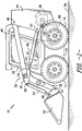
- FIG. 1 illustrates a side view of one embodiment of a work vehicle 10 in accordance with aspects of the present subject matter.
- the work vehicle 10 is configured as a skid steer loader.
- the work vehicle 10 may be configured as any other suitable work vehicle known in the art, such as any other vehicle including a lift assembly that allows for the maneuvering of an implement (e.g., telescopic handlers, wheel loaders, backhoe loaders, forklifts, compact track loaders, bulldozers and/or the like).
- a lift assembly that allows for the maneuvering of an implement (e.g., telescopic handlers, wheel loaders, backhoe loaders, forklifts, compact track loaders, bulldozers and/or the like).
- the work vehicle 10 includes a pair of front wheels 12, (one of which is shown), a pair of rear wheels 16 (one of which is shown) and a chassis 20 coupled to and supported by the wheels 12, 16.
- An operator's cab 22 may be supported by a portion of the chassis 20 and may house various input devices, such as one or more speed control joysticks 24 and one or more lift/tilt joysticks 25, for permitting an operator to control the operation of the work vehicle 10.
- the work vehicle 10 may include an engine 26 and a hydrostatic drive unit 28 coupled to or otherwise supported by the chassis 20. More specifically, the hydrostatic drive unit 28 is configured to drive a braking system 60 of the work vehicle 10, which is described in more detail below with reference to FIG. 2 .
- the work vehicle 10 may also include a lift assembly 30 for raising and lowering a suitable implement 32 (e.g., a bucket) relative to a driving surface 34 of the vehicle 10.
- the lift assembly 30 may include a pair of loader arms 36 (one of which is shown) pivotally coupled between the chassis 20 and the implement 32.
- a suitable implement 32 e.g., a bucket
- the lift assembly 30 may include a pair of loader arms 36 (one of which is shown) pivotally coupled between the chassis 20 and the implement 32.
- each loader arm 36 may be configured to extend lengthwise between a forward end 38 and an aft end 40, with the forward end 38 being pivotally coupled to the implement 32 at a forward pivot point 42 and the aft end 40 being pivotally coupled to the chassis 20 (or a rear tower(s) 44 coupled to or otherwise supported by the chassis 20) at a rear pivot point 46.
- the lift assembly 30 may also include a pair of hydraulic lift cylinders 48 coupled between the chassis 20 (e.g., at the rear tower(s) 44) and the loader arms 36 and a pair of hydraulic tilt cylinders 50 coupled between the loader arms 36 and the implement 32.
- each lift cylinder 48 may be pivotally coupled to the chassis 20 at a lift pivot point 52 and may extend outwardly therefrom so to be coupled to its corresponding loader arm 36 at an intermediate attachment location 54 defined between the forward and aft ends 38, 40 of each loader arm 36.
- each tilt cylinder 50 may be coupled to its corresponding loader arm 36 at a first attachment location 56 and may extend outwardly therefrom so as to be coupled to the implement 32 at a second attachment location 58.
- the lift and tilt cylinders 48, 50 may be utilized to allow the implement 32 to be raised/lowered and/or pivoted relative to the driving surface 34 of the work vehicle 10.
- the lift cylinders 48 may be extended and retracted in order to pivot the loader arms 36 upward and downwards, respectively, about the rear pivot point 52, thereby at least partially controlling the vertical positioning of the implement 32 relative to the driving surface 34.
- the tilt cylinders 50 may be extended and retracted in order to pivot the implement 32 relative to the loader arms 36 about the forward pivot point 42, thereby controlling the tilt angle or orientation of the implement 32 relative to the driving surface 34.
- the braking system 60 includes a dual-path hydrostatic transmission having left and right braking mechanisms 62, 64 controlled by left and right brake pedals (not shown).
- the braking system 60 includes two (i.e. left and right) braking circuits.
- the braking mechanisms 62, 64 may include one or more brake cylinders or a clutch drive system.
- each braking mechanism 62, 64 may include an outer housing 66, 68 with a piston 70, 72 configured therein.
- the piston 70, 72 may be surrounded by a brake spring 65, 67 that is moved via an actuating rod 74, 76 connected to respective brake pedals.
- the braking system 60 further includes an electrically-actuated two-position, three-way primary release valve 82 positioned between the braking mechanism(s) 62, 64 and a reservoir 88.
- the braking system 60 also includes a secondary release valve 86.
- the braking mechanisms 62, 64 are individually (i.e. independently) coupled to the primary release valve 82 and the secondary release valve 86 via one or more hydraulic lines 78, 80. In other words, the secondary release valve 86 is not hydraulically coupled to the primary release valve 82.
- the primary release valve 82 is energized so as to overcome valve biasing spring 90, thereby shifting the valve 82 and directing the pressurized hydraulic fluid from the reservoir 88 to the braking mechanism(s) 62, 64.
- the pressurized hydraulic fluid overcomes the brake springs 65, 67 and the brakes are released as long as pressurized hydraulic fluid is supplied thereto.
- the braking system 60 may include a control system 75 and at least one primary pumping device 77 having a pumping motor 79.
- the primary release valve 82 is energized via the control system 75, whereas the primary pumping device 77 pressurizes the hydraulic fluid in the hydraulic lines 78, 80.
- the control system 75 may be configured to transmit suitable control commands to the valves 82, 84 in order to regulate the flow of hydraulic fluid supplied to the braking mechanism 62, 64, thereby allowing for control of a stroke length of the pistons 70, 72 associated with each cylinder 62, 64.
- the primary release valve 82 remains inactive so as to allow the hydraulic fluid to flow away from the braking mechanism(s) 62, 64 to the reservoir 88 such that brake springs 65, 67 compress the braking mechanism(s) 62, 64.
- the braking mechanism(s) 62, 64 will automatically be compressed because of the loss of pressurized hydraulic fluid.
- the brake cylinders 62, 64 remain locked due to the loss of pressurized fluid being supplied thereto, thereby making towing of the work vehicle 10 nearly impossible.
- the operator needs to be able to release the brakes such that the work vehicle 10 can be easily moved or towed.
- the secondary release valve 86 is provided to bypass the primary release valve 82 in the event of such a power outage, so as to direct pressurized hydraulic fluid to the braking mechanisms 62, 64 and release the brakes.
- the braking system 60 may also include a secondary pumping device 96 hydraulically coupled with the secondary release valve 86 via a secondary hydraulic line 95.
- the secondary pumping device 96 pressurizes the hydraulic fluid that is directed to the braking mechanisms 62, 64.
- the secondary pumping device 96 may include a manually-operated pumping device (i.e. a hand pump), an electrical pumping device, and/or a hydraulic pumping device configured with a secondary reservoir 98.
- the secondary pumping device 96 may be remotely-controlled by the operator. As such, the operator can easily pressurize the hydraulic fluid without needing access to the braking system 60.
- the braking system 60 may also include a safety valve 84 hydraulically coupled between the primary release valve 82 and the braking mechanisms 62, 64.
- the safety valve 84 is configured to drain the control system 75 to ensure that the control system75 returns to a neutral state and the primary pumping device 77 does not send hydraulic fluid to the pumping motor 79.
- the primary reservoir 88 may be hydraulically coupled to the primary release valve 82 and the safety valve 84, but not the secondary release valve 86.
- the secondary release valve 86 and the secondary reservoir 98 provide an independent pressurizing system for the braking mechanisms 62, 64 that bypasses the primary system in the event of a power loss.
- the primary release valve 82, the secondary release valve 86, and/or the safety valve 84 may include any suitable valves, such as, for example, solenoid valves. More specifically, in particular embodiments, the primary release valve 82 and the secondary release valve 86 may include two-position, three-way solenoid valves, whereas the safety valve 84 may include a two-position, two-way solenoid valve. Alternatively, the safety valve 84 may include a two-position, four-way solenoid valve. In further embodiments, as shown, the primary release valve 82 may include an electrically-actuated valve, whereas the secondary release valve 86 and/or the safety valve 84 may include a pilot-actuated valve.
- control system 75 may be configured to electronically control the operation of one or more components of the work vehicle 10, such as the various hydraulic components of the work vehicle 10 (e.g., the braking mechanism 62, 67 and valves 82, 84, 86).
- the control system 75 may comprise any suitable processor-based device known in the art, such as a computing device or any suitable combination of computing devices.
- the control system 75 may include one or more processor(s) 83 and associated memory device(s) 85 configured to perform a variety of computer-implemented functions.
- processor refers not only to integrated circuits referred to in the art as being included in a computer, but also refers to a controller, a microcontroller, a microcomputer, a programmable logic controller (PLC), an application specific integrated circuit, and other programmable circuits.
- PLC programmable logic controller
- the memory device(s) 85 of the control system 75 may generally comprise memory element(s) including, but are not limited to, computer readable medium (e.g., random access memory (RAM)), computer readable nonvolatile medium (e.g., a flash memory), a floppy disk, a compact disc-read only memory (CD-ROM), a magneto-optical disk (MOD), a digital versatile disc (DVD) and/or other suitable memory elements.
- RAM random access memory
- computer readable nonvolatile medium e.g., a flash memory
- CD-ROM compact disc-read only memory
- MOD magneto-optical disk
- DVD digital versatile disc
- Such memory device(s) 85 may generally be configured to store suitable computer-readable instructions that, when implemented by the processor(s) 83, configure the control system 75 to perform various computer-implemented functions.
- the control system 75 may also include various other suitable components, such as a communications circuit or module, one or more input/output channels, a data/control bus and/
- control system 75 may correspond to an existing controller of the work vehicle 10 or the control system 75 may correspond to a separate processing device.
- the control system 75 may form all or part of a separate plug-in module that may be installed within the work vehicle 10 to allow for the disclosed system and method to be implemented without requiring additional software to be uploaded onto existing control devices of the vehicle 10.
- the method 100 includes hydraulically coupling a secondary release valve 86 to at least one braking mechanism(s) 62, 64 of the braking system 60 having one or more brake springs 65, 67 via a secondary hydraulic line (e.g. lines 78, 80).
- a secondary hydraulic line e.g. lines 78, 80
- the secondary hydraulic line 78, 80 bypasses an electrically-actuated primary release valve 82 of the braking system 60.
- the method 100 also includes directing pressurized hydraulic fluid via the secondary release valve 86 to the braking mechanism(s) 62, 64 to release the brakes during the power outage.
- the method 100 further includes pressurizing the hydraulic fluid via a secondary pumping device 96 hydraulically coupled with the secondary release valve 86. In another embodiment, the method 100 includes controlling the secondary pumping device remotely.
Landscapes
- Engineering & Computer Science (AREA)
- Mechanical Engineering (AREA)
- Transportation (AREA)
- General Engineering & Computer Science (AREA)
- Mining & Mineral Resources (AREA)
- Civil Engineering (AREA)
- Structural Engineering (AREA)
- Chemical & Material Sciences (AREA)
- Combustion & Propulsion (AREA)
- Regulating Braking Force (AREA)
- Braking Systems And Boosters (AREA)
Abstract
Description
- The present subject matter relates generally to work vehicles and, more particularly, to a system and method for remotely releasing the braking system of a work vehicle during loss of power.
- Work vehicles having loader arms, such as skid steer loaders, telescopic handlers, wheel loaders, backhoe loaders, forklifts, compact track loaders and the like, are a mainstay of construction work and industry. For example, skid steer loaders typically include a pair of loader arms pivotally coupled to the vehicle's chassis that can be raised and lowered at the operator's command. The loader arms typically have an implement attached to their end, thereby allowing the implement to be moved relative to the ground as the loader arms are raised and lowered. For example, a bucket is often coupled to the loader arm, which allows the skid steer loader to be used to carry supplies or particulate matter, such as gravel, sand, or dirt, around a worksite. Oftentimes, such work vehicles are driven by a hydrostatic drive system.
- Work vehicle braking systems are often operated manually by an operator pressing one or more brake pedals. For example, certain agricultural, work, and off-road vehicles, may have two brake pedals, one brake pedal for the left brakes and another brake pedal for the right brakes. In addition, the hydrostatic drive system of the work vehicle is often used for braking. Thus, the braking system generally includes a reservoir of pressurized fluid hydraulically connected to one or more brake cylinders that is, in turn, connected to a controlling mechanism via one or more hydraulic lines. As such, the brakes are released and compressed by directing pressurized brake fluid between the controlling mechanism and the brake cylinders.
- When such braking systems experience a power outage, the brakes lock up since the system can no longer supply the needed pressurized fluid to the braking cylinders. However, in order to move and/or tow the work vehicle to a safe location, the operator needs to be able to release the brakes during such power losses. One issue with releasing the brakes during power losses is that it is often difficult for an operator to access the braking system to make necessary repairs.
- Accordingly, an improved system and method for remotely releasing the brakes of a work vehicle during loss of power would be welcomed in the art.
- Aspects and advantages of the invention will be set forth in part in the following description, or may be obvious from the description, or may be learned through practice of the invention.
- In one aspect, the present subject matter is directed to a braking system for a work vehicle having hydraulically-actuated brakes. The braking system includes a primary release valve, a secondary release valve, and at least one braking mechanism having one or more brake springs. The braking mechanism(s) is hydraulically coupled to the primary release valve and the secondary release valve via one or more hydraulic lines. As such, during full-power operation of the work vehicle, when the brakes are to be released, the primary release valve is energized so as to overcome a valve biasing spring, thereby shifting the primary release valve so as to direct pressurized hydraulic fluid to the braking mechanism(s). Further, when the brakes are to be applied, the primary release valve is inactive so as to allow the hydraulic fluid to flow away from the braking mechanism(s) to a primary reservoir such that the one or more brake springs compress the braking mechanism(s). Alternatively, when power is lost to the work vehicle, the secondary release valve bypasses the primary release valve and directs pressurized hydraulic fluid to the braking mechanism(s) to release the brakes.
- In another aspect, the present subject matter is directed to a work vehicle. The work vehicle includes a pair of front wheels, a pair of rear wheels, a chassis coupled to and supported by the wheels, and a braking system having hydraulically-actuated brakes that are coupled to the front and rear wheels. The braking system includes a primary release valve, a secondary release valve, and at least one braking mechanism having one or more brake springs. The braking mechanism is hydraulically coupled to the primary release valve and the secondary release valve via one or more hydraulic lines. As such, during full-power operation of the work vehicle, when the brakes are to be released, the primary release valve is energized so as to overcome a valve biasing spring, thereby shifting the primary release valve so as to direct pressurized hydraulic fluid to the braking mechanism. Further, when the brakes are to be applied, the primary release valve is inactive so as to allow the hydraulic fluid to flow away from the braking mechanism(s) to a primary reservoir such that the one or more brake springs compress the braking mechanism(s). Alternatively, when power is lost to the work vehicle, the secondary release valve bypasses the primary release valve and directs pressurized hydraulic fluid to the braking mechanism to release the brakes.
- In yet another aspect, the present subject matter is directed to a method for operating a braking system of a work vehicle having hydraulically-actuated brakes during a power outage. The method includes hydraulically coupling a secondary release valve to at least one braking mechanism of the braking system having one or more brake springs via a secondary hydraulic line. As such, the secondary hydraulic line bypasses an electrically-actuated primary release valve of the braking system. Thus, the method also includes directing pressurized hydraulic fluid via the secondary release valve to the braking mechanism to release the brakes during the power outage.
- These and other features, aspects and advantages of the present invention will become better understood with reference to the following description and appended claims. The accompanying drawings, which are incorporated in and constitute a part of this specification, illustrate embodiments of the invention and, together with the description, serve to explain the principles of the invention.
- A full and enabling disclosure of the present invention, including the best mode thereof, directed to one of ordinary skill in the art, is set forth in the specification, which makes reference to the appended figures, in which:
-
FIG. 1 illustrates a side view of one embodiment of a work vehicle according to the present disclosure; -
FIG. 2 illustrates a schematic view of one embodiment of a suitable braking system for a work vehicle according to the present disclosure; and -
FIG. 3 illustrates a flow diagram of one embodiment of a method for operating a braking system of a work vehicle having hydraulically-actuated brakes during a power outage according to the present disclosure. - Reference now will be made in detail to embodiments of the invention, one or more examples of which are illustrated in the drawings. Each example is provided by way of explanation of the invention, not limitation of the invention. In fact, it will be apparent to those skilled in the art that various modifications and variations can be made in the present invention without departing from the scope or spirit of the invention. For instance, features illustrated or described as part of one embodiment can be used with another embodiment to yield a still further embodiment. Thus, it is intended that the present invention covers such modifications and variations as come within the scope of the appended claims and their equivalents.
- Referring now to the drawings,
FIG. 1 illustrates a side view of one embodiment of awork vehicle 10 in accordance with aspects of the present subject matter. As shown, thework vehicle 10 is configured as a skid steer loader. However, in other embodiments, thework vehicle 10 may be configured as any other suitable work vehicle known in the art, such as any other vehicle including a lift assembly that allows for the maneuvering of an implement (e.g., telescopic handlers, wheel loaders, backhoe loaders, forklifts, compact track loaders, bulldozers and/or the like). - As shown, the
work vehicle 10 includes a pair offront wheels 12, (one of which is shown), a pair of rear wheels 16 (one of which is shown) and achassis 20 coupled to and supported by thewheels cab 22 may be supported by a portion of thechassis 20 and may house various input devices, such as one or morespeed control joysticks 24 and one or more lift/tilt joysticks 25, for permitting an operator to control the operation of thework vehicle 10. In addition, thework vehicle 10 may include anengine 26 and ahydrostatic drive unit 28 coupled to or otherwise supported by thechassis 20. More specifically, thehydrostatic drive unit 28 is configured to drive abraking system 60 of thework vehicle 10, which is described in more detail below with reference toFIG. 2 . - Moreover, as shown in
FIG. 1 , thework vehicle 10 may also include alift assembly 30 for raising and lowering a suitable implement 32 (e.g., a bucket) relative to adriving surface 34 of thevehicle 10. In several embodiments, thelift assembly 30 may include a pair of loader arms 36 (one of which is shown) pivotally coupled between thechassis 20 and theimplement 32. For example, as shown inFIG. 1 , eachloader arm 36 may be configured to extend lengthwise between aforward end 38 and anaft end 40, with theforward end 38 being pivotally coupled to theimplement 32 at aforward pivot point 42 and theaft end 40 being pivotally coupled to the chassis 20 (or a rear tower(s) 44 coupled to or otherwise supported by the chassis 20) at arear pivot point 46. - In addition, the
lift assembly 30 may also include a pair ofhydraulic lift cylinders 48 coupled between the chassis 20 (e.g., at the rear tower(s) 44) and theloader arms 36 and a pair ofhydraulic tilt cylinders 50 coupled between theloader arms 36 and theimplement 32. For example, as shown in the illustrated embodiment, eachlift cylinder 48 may be pivotally coupled to thechassis 20 at alift pivot point 52 and may extend outwardly therefrom so to be coupled to itscorresponding loader arm 36 at anintermediate attachment location 54 defined between the forward andaft ends loader arm 36. Similarly, eachtilt cylinder 50 may be coupled to itscorresponding loader arm 36 at afirst attachment location 56 and may extend outwardly therefrom so as to be coupled to theimplement 32 at asecond attachment location 58. - It should be readily understood by those of ordinary skill in the art that the lift and
tilt cylinders implement 32 to be raised/lowered and/or pivoted relative to thedriving surface 34 of thework vehicle 10. For example, thelift cylinders 48 may be extended and retracted in order to pivot theloader arms 36 upward and downwards, respectively, about therear pivot point 52, thereby at least partially controlling the vertical positioning of theimplement 32 relative to thedriving surface 34. Similarly, thetilt cylinders 50 may be extended and retracted in order to pivot theimplement 32 relative to theloader arms 36 about theforward pivot point 42, thereby controlling the tilt angle or orientation of theimplement 32 relative to thedriving surface 34. - It should be appreciated that the configuration of the
work vehicle 10 described above and shown inFIG. 1 is provided only to place the present subject matter in an exemplary field of use. Thus, it should be appreciated that the present subject matter may be readily adaptable to any manner of work vehicle configuration. - Referring now to
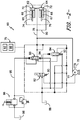
FIG. 2 , a schematic diagram of one embodiment of thebraking system 60 having hydraulically-actuated brakes is illustrated. More specifically, as shown, thebraking system 60 includes a dual-path hydrostatic transmission having left andright braking mechanisms 62, 64 controlled by left and right brake pedals (not shown). As such, thebraking system 60 includes two (i.e. left and right) braking circuits. More specifically, in one embodiment, the brakingmechanisms 62, 64 may include one or more brake cylinders or a clutch drive system. For example, as shown, eachbraking mechanism 62, 64 may include anouter housing piston piston brake spring actuating rod - Still referring to
FIG. 2 , thebraking system 60 further includes an electrically-actuated two-position, three-wayprimary release valve 82 positioned between the braking mechanism(s) 62, 64 and areservoir 88. In addition, thebraking system 60 also includes asecondary release valve 86. Further, as shown, the brakingmechanisms 62, 64 are individually (i.e. independently) coupled to theprimary release valve 82 and thesecondary release valve 86 via one or morehydraulic lines secondary release valve 86 is not hydraulically coupled to theprimary release valve 82. Thus, during full-power operation of thework vehicle 10, when the brakes are to be released, theprimary release valve 82 is energized so as to overcomevalve biasing spring 90, thereby shifting thevalve 82 and directing the pressurized hydraulic fluid from thereservoir 88 to the braking mechanism(s) 62, 64. As such, the pressurized hydraulic fluid overcomes the brake springs 65, 67 and the brakes are released as long as pressurized hydraulic fluid is supplied thereto. - For example, in one embodiment, the
braking system 60 may include acontrol system 75 and at least oneprimary pumping device 77 having a pumpingmotor 79. In such embodiments, theprimary release valve 82 is energized via thecontrol system 75, whereas theprimary pumping device 77 pressurizes the hydraulic fluid in thehydraulic lines control system 75 may be configured to transmit suitable control commands to thevalves braking mechanism 62, 64, thereby allowing for control of a stroke length of thepistons cylinder 62, 64. To apply the brakes during full-power operation of thework vehicle 10, theprimary release valve 82 remains inactive so as to allow the hydraulic fluid to flow away from the braking mechanism(s) 62, 64 to thereservoir 88 such that brake springs 65, 67 compress the braking mechanism(s) 62, 64. - If the
work vehicle 10 is shut down or hydraulic pressure is lost for any reason (e.g. due to a power outage), however, the braking mechanism(s) 62, 64 will automatically be compressed because of the loss of pressurized hydraulic fluid. In other words, in the event of a power loss, thebrake cylinders 62, 64 remain locked due to the loss of pressurized fluid being supplied thereto, thereby making towing of thework vehicle 10 nearly impossible. Thus, the operator needs to be able to release the brakes such that thework vehicle 10 can be easily moved or towed. As such, thesecondary release valve 86 is provided to bypass theprimary release valve 82 in the event of such a power outage, so as to direct pressurized hydraulic fluid to thebraking mechanisms 62, 64 and release the brakes. - In addition, as shown, the
braking system 60 may also include asecondary pumping device 96 hydraulically coupled with thesecondary release valve 86 via a secondaryhydraulic line 95. As such, when power is lost, thesecondary pumping device 96 pressurizes the hydraulic fluid that is directed to thebraking mechanisms 62, 64. In certain embodiments, for example, thesecondary pumping device 96 may include a manually-operated pumping device (i.e. a hand pump), an electrical pumping device, and/or a hydraulic pumping device configured with asecondary reservoir 98. In one embodiment, thesecondary pumping device 96 may be remotely-controlled by the operator. As such, the operator can easily pressurize the hydraulic fluid without needing access to thebraking system 60. - Still referring to
FIG. 2 , thebraking system 60 may also include asafety valve 84 hydraulically coupled between theprimary release valve 82 and thebraking mechanisms 62, 64. Thus, in certain embodiments, thesafety valve 84 is configured to drain thecontrol system 75 to ensure that the control system75 returns to a neutral state and theprimary pumping device 77 does not send hydraulic fluid to the pumpingmotor 79. In addition, as shown in the illustrated embodiment, theprimary reservoir 88 may be hydraulically coupled to theprimary release valve 82 and thesafety valve 84, but not thesecondary release valve 86. As such, thesecondary release valve 86 and thesecondary reservoir 98 provide an independent pressurizing system for thebraking mechanisms 62, 64 that bypasses the primary system in the event of a power loss. - It should be understood that the the
primary release valve 82, thesecondary release valve 86, and/or thesafety valve 84 may include any suitable valves, such as, for example, solenoid valves. More specifically, in particular embodiments, theprimary release valve 82 and thesecondary release valve 86 may include two-position, three-way solenoid valves, whereas thesafety valve 84 may include a two-position, two-way solenoid valve. Alternatively, thesafety valve 84 may include a two-position, four-way solenoid valve. In further embodiments, as shown, theprimary release valve 82 may include an electrically-actuated valve, whereas thesecondary release valve 86 and/or thesafety valve 84 may include a pilot-actuated valve. - In addition, it should be understood that the
control system 75 as described herein may be configured to electronically control the operation of one or more components of thework vehicle 10, such as the various hydraulic components of the work vehicle 10 (e.g., thebraking mechanism 62, 67 andvalves control system 75 may comprise any suitable processor-based device known in the art, such as a computing device or any suitable combination of computing devices. Thus, in several embodiments, thecontrol system 75 may include one or more processor(s) 83 and associated memory device(s) 85 configured to perform a variety of computer-implemented functions. As used herein, the term "processor" refers not only to integrated circuits referred to in the art as being included in a computer, but also refers to a controller, a microcontroller, a microcomputer, a programmable logic controller (PLC), an application specific integrated circuit, and other programmable circuits. - Additionally, the memory device(s) 85 of the
control system 75 may generally comprise memory element(s) including, but are not limited to, computer readable medium (e.g., random access memory (RAM)), computer readable nonvolatile medium (e.g., a flash memory), a floppy disk, a compact disc-read only memory (CD-ROM), a magneto-optical disk (MOD), a digital versatile disc (DVD) and/or other suitable memory elements. Such memory device(s) 85 may generally be configured to store suitable computer-readable instructions that, when implemented by the processor(s) 83, configure thecontrol system 75 to perform various computer-implemented functions. In addition, thecontrol system 75 may also include various other suitable components, such as a communications circuit or module, one or more input/output channels, a data/control bus and/or the like. - In addition, it should be appreciated that the
control system 75 may correspond to an existing controller of thework vehicle 10 or thecontrol system 75 may correspond to a separate processing device. For instance, in one embodiment, thecontrol system 75 may form all or part of a separate plug-in module that may be installed within thework vehicle 10 to allow for the disclosed system and method to be implemented without requiring additional software to be uploaded onto existing control devices of thevehicle 10. - Referring now to
FIG. 3 , a flow diagram of one embodiment of amethod 100 for operating abraking system 60 of awork vehicle 10 having hydraulically-actuated brakes during a power outage is illustrated. For example, as shown at 102, themethod 100 includes hydraulically coupling asecondary release valve 86 to at least one braking mechanism(s) 62, 64 of thebraking system 60 having one or more brake springs 65, 67 via a secondary hydraulic line (e.g. lines 78, 80). As such, the secondaryhydraulic line primary release valve 82 of thebraking system 60. Thus, as shown at 104, themethod 100 also includes directing pressurized hydraulic fluid via thesecondary release valve 86 to the braking mechanism(s) 62, 64 to release the brakes during the power outage. - In one embodiment, the
method 100 further includes pressurizing the hydraulic fluid via asecondary pumping device 96 hydraulically coupled with thesecondary release valve 86. In another embodiment, themethod 100 includes controlling the secondary pumping device remotely. - This written description uses examples to disclose the invention, including the best mode, and also to enable any person skilled in the art to practice the invention, including making and using any devices or systems and performing any incorporated methods. The patentable scope of the invention is defined by the claims, and may include other examples that occur to those skilled in the art. Such other examples are intended to be within the scope of the claims if they include structural elements that do not differ from the literal language of the claims, or if they include equivalent structural elements with insubstantial differences from the literal languages of the claims.
Claims (15)
- A braking system (60) for a work vehicle (10) having hydraulically-actuated brakes, the braking system having a primary release valve (82) and at least one braking mechanism (62, 64) comprising one or more brake springs (65, 67), the braking system (60) characterized by:a secondary release valve (86), the braking mechanism (62, 64) hydraulically coupled to the primary release valve (82) and the secondary release valve (86) via one or more hydraulic lines,wherein, during full-power operation of the work vehicle (10), when the brakes are to be released, the primary release valve (82) is energized so as to overcome a valve biasing spring (90), thereby shifting the primary release valve (82) so as to direct pressurized hydraulic fluid to the braking mechanism (62, 64), and wherein, when the brakes are to be applied, the primary release valve (82) is inactive so as to allow the hydraulic fluid to flow away from the braking mechanism to a primary reservoir (88) such that the one or more brake springs (65, 67) compress the brake mechanism, andwherein, when power is lost to the work vehicle (10), the secondary release valve (86) bypasses the primary release valve (82) and directs pressurized hydraulic fluid to the braking mechanism (62, 64) to release the brakes.
- The braking system (60) of claim 1, wherein the at least one braking mechanism (62, 64) comprises at least one of one or more brake cylinders or a clutch drive system.
- The braking system (60) of claims 1 or 2, wherein the at least one braking mechanism (62, 64) comprises a right braking mechanism (62, 64) and a left braking mechanism (62, 64).
- The braking system (60) of claims 1, 2, or 3, further comprising a control system (75) and at least one primary pumping device (77) having a pumping motor (79), wherein the primary release valve (82) is energized via the control system (75), and wherein the primary pumping device (77) pressurizes the hydraulic fluid.
- The braking system (60) of any of the preceding claims, further comprising a secondary pumping device (96) hydraulically coupled with the secondary release valve (86) via a secondary hydraulic line (95), wherein, when power is lost, the secondary pumping device (96) pressurizes the hydraulic fluid that is directed to the braking mechanism (62, 64).
- The braking system (60) of claim 4, further comprising a safety valve (84) hydraulically coupled between the primary release valve (82) and the at least one braking mechanism (62, 64), the safety valve (84) configured to drain the control system (75) to ensure that the control system (75) returns to a neutral state and the primary pumping device (77) does not send the hydraulic fluid to the pumping motor (79).
- The braking system (60) of claim 5, wherein the secondary pumping device (96) comprises at least one of a manually-operated pumping device, an electrical pumping device, or a hydraulic pumping device configured with a secondary reservoir.
- The braking system (60) of claim 5, wherein the secondary pumping device (96) is remotely-controlled.
- The braking system (60) of claim 6, wherein the primary reservoir (88) is hydraulically coupled to the primary release valve (82) and the safety valve (84), but not the secondary release valve (86).
- The braking system (60) of any of the preceding claims, wherein the primary release valve (82) and the secondary release valve (86) comprise two-position, three-way solenoid valves.
- The braking system (60) of claim 6, wherein the safety valve (84) comprises at least one of a two-position, two-way solenoid valve or a two-position, four-way solenoid valve.
- The braking system (60) of claim 9, wherein the primary release valve (82) comprises an electrically-actuated valve, and wherein, the secondary release valve (86) and the safety valve (84) comprise a pilot-actuated valve.
- A method (100) for operating a braking system (60) of a work vehicle (10) having hydraulically-actuated brakes during a power outage, the method (100) characterized by:hydraulically coupling a secondary release valve (86) to at least one braking mechanism (62, 64) of the braking system (60) having one or more brake springs (65, 67) via a secondary hydraulic line (95), the secondary hydraulic line (95) bypassing an electrically-actuated primary release valve (82) of the braking system (60); anddirecting pressurized hydraulic fluid to the braking mechanism (62, 64) via the secondary release valve (86) to release the brakes during the power outage.
- The method (100) of claim 13, further comprising pressurizing the hydraulic fluid via a secondary pumping device (96) hydraulically coupled with the secondary release valve (86).
- The method (100) of claims 13 or 14, further comprising controlling the secondary pumping device (96) remotely.
Applications Claiming Priority (1)
| Application Number | Priority Date | Filing Date | Title |
|---|---|---|---|
| US15/444,781 US10562507B2 (en) | 2017-02-28 | 2017-02-28 | Work vehicle with remote brake release |
Publications (1)
| Publication Number | Publication Date |
|---|---|
| EP3366846A1 true EP3366846A1 (en) | 2018-08-29 |
Family
ID=61283080
Family Applications (1)
| Application Number | Title | Priority Date | Filing Date |
|---|---|---|---|
| EP18158629.8A Withdrawn EP3366846A1 (en) | 2017-02-28 | 2018-02-26 | Work vehicle with remote brake release |
Country Status (3)
| Country | Link |
|---|---|
| US (1) | US10562507B2 (en) |
| EP (1) | EP3366846A1 (en) |
| BR (1) | BR102018004043A2 (en) |
Cited By (1)
| Publication number | Priority date | Publication date | Assignee | Title |
|---|---|---|---|---|
| CN113734123A (en) * | 2021-09-22 | 2021-12-03 | 一汽解放汽车有限公司 | Automatic driving hydraulic braking system |
Families Citing this family (2)
| Publication number | Priority date | Publication date | Assignee | Title |
|---|---|---|---|---|
| EP4110643A1 (en) * | 2020-02-27 | 2023-01-04 | CNH Industrial Italia S.P.A. | An electric work vehicle having an electric drivetrain and storage component configuration |
| US11724672B2 (en) | 2020-11-19 | 2023-08-15 | Bendix Commercial Vehicle Systems Llc | System and method for controlling an electronic parking brake |
Citations (4)
| Publication number | Priority date | Publication date | Assignee | Title |
|---|---|---|---|---|
| US4856622A (en) * | 1987-11-16 | 1989-08-15 | Caterpillar Inc. | Auxiliary actuation mechanism for a brake assembly |
| US5984425A (en) * | 1998-01-22 | 1999-11-16 | Wacker Corporation | Spring applied/hydraulically released braking system employing self-resetting override valve |
| US20030155807A1 (en) * | 2002-02-21 | 2003-08-21 | Deere & Company, A Delaware Corporation | Brake release system |
| EP2974926A1 (en) * | 2014-06-24 | 2016-01-20 | CNH Industrial Italia S.p.A. | Braking system for a work vehicle |
Family Cites Families (15)
| Publication number | Priority date | Publication date | Assignee | Title |
|---|---|---|---|---|
| US2430954A (en) | 1944-06-12 | 1947-11-18 | Wagner Electric Corp | Bleeding mechanism for hydraulic brakes |
| US2963117A (en) * | 1956-10-22 | 1960-12-06 | Daniel F Mcgill | Hydraulic braking system |
| US3981545A (en) * | 1975-07-30 | 1976-09-21 | Aspro, Incorporated | Traction control apparatus |
| ZA826331B (en) * | 1981-09-11 | 1983-07-27 | Westinghouse Brake & Signal | Control valve arrangement |
| US5605384A (en) | 1996-05-06 | 1997-02-25 | General Motors Corporation | Access valve evacuation and fill of inaccessible cavities |
| WO1999032339A1 (en) | 1997-12-23 | 1999-07-01 | Kelsey-Hayes Company | Vehicular brake system with vehicle stability control having evacuation valve |
| DE19906710A1 (en) * | 1998-03-18 | 1999-09-23 | Heidelberger Druckmasch Ag | Sheet unroller for printing machines based on vacuumed pull-down grooves |
| US6290024B1 (en) * | 2000-03-03 | 2001-09-18 | Lubrication Systems Company Of Texas, Inc. | Oil mist generating system |
| US6477836B1 (en) * | 2000-10-26 | 2002-11-12 | Caterpillar Inc. | Pilot control system |
| FR2823707B1 (en) * | 2001-04-23 | 2003-08-15 | Poclain Hydraulics Ind | HYDRAULIC CIRCUIT HAVING A HYDRAULIC MOTOR EQUIPPED WITH A BRAKE FOR A VEHICLE CAPABLE OF BEING TOWED |
| EP1901950B1 (en) * | 2005-07-08 | 2016-06-15 | FSP Fluid Systems Partners Holding AG | Process for releasing of at least one spring-loaded brake by means of a pressure means as well as device and hydraulic control circuit for the execution of the process |
| US7452038B2 (en) | 2006-01-20 | 2008-11-18 | Towhaul Corporation | System and method for remotely releasing a parking brake on a disabled vehicle |
| US20070257553A1 (en) * | 2006-05-02 | 2007-11-08 | Ford Global Technologies, Llc | Method to Achieve Pressure Control Robustness in Brake Control Systems |
| DE102011077786A1 (en) | 2011-06-20 | 2012-12-20 | Continental Teves Ag & Co. Ohg | Actuator system and operating method for an actuator system |
| GB2502252B (en) | 2012-03-26 | 2018-09-05 | Knorr Bremse Rail Systems Uk Ltd | Emergency braking |
-
2017
- 2017-02-28 US US15/444,781 patent/US10562507B2/en active Active
-
2018
- 2018-02-26 EP EP18158629.8A patent/EP3366846A1/en not_active Withdrawn
- 2018-02-28 BR BR102018004043-0A patent/BR102018004043A2/en not_active Application Discontinuation
Patent Citations (4)
| Publication number | Priority date | Publication date | Assignee | Title |
|---|---|---|---|---|
| US4856622A (en) * | 1987-11-16 | 1989-08-15 | Caterpillar Inc. | Auxiliary actuation mechanism for a brake assembly |
| US5984425A (en) * | 1998-01-22 | 1999-11-16 | Wacker Corporation | Spring applied/hydraulically released braking system employing self-resetting override valve |
| US20030155807A1 (en) * | 2002-02-21 | 2003-08-21 | Deere & Company, A Delaware Corporation | Brake release system |
| EP2974926A1 (en) * | 2014-06-24 | 2016-01-20 | CNH Industrial Italia S.p.A. | Braking system for a work vehicle |
Cited By (1)
| Publication number | Priority date | Publication date | Assignee | Title |
|---|---|---|---|---|
| CN113734123A (en) * | 2021-09-22 | 2021-12-03 | 一汽解放汽车有限公司 | Automatic driving hydraulic braking system |
Also Published As
| Publication number | Publication date |
|---|---|
| US20180244252A1 (en) | 2018-08-30 |
| BR102018004043A2 (en) | 2019-01-15 |
| US10562507B2 (en) | 2020-02-18 |
Similar Documents
| Publication | Publication Date | Title |
|---|---|---|
| CN102149583B (en) | Method for operating brake system of work machine and brake system for work machine | |
| US4856622A (en) | Auxiliary actuation mechanism for a brake assembly | |
| US20140062178A1 (en) | Method and system for releasing parking brake of an anchored machine and a machine with the same | |
| EP3366846A1 (en) | Work vehicle with remote brake release | |
| CN108082158A (en) | Vehicle block selecting, stopping brake combined control system | |
| CN110719864B (en) | Brake system, mining vehicle and method for releasing brake | |
| US10745885B2 (en) | System for operating a circle drive gear of a machine | |
| US9533535B2 (en) | Drive unit for a rail-road vehicle | |
| CN117141434A (en) | Mining dump truck wire-controlled proportional driverless braking system and its use method | |
| US3437184A (en) | Method of neutralizing transmission and braking vehicle when shifting between forward and reverse | |
| CA2674293A1 (en) | Freely rotatable closed grapple head and machine using same | |
| US3827528A (en) | Low cost auxiliary hydrostatic drive for trucks | |
| CN104736857B (en) | Double priority valve | |
| US6715590B2 (en) | Brake release system | |
| US10479336B2 (en) | Vehicle brake system | |
| JP2019048522A (en) | Transport vehicle | |
| US5052532A (en) | Vehicle brake system | |
| US20170036656A1 (en) | Hydraulic control system for parking brake | |
| US5232271A (en) | Brake system for automatic disablement of towed vehicle brakes during backing | |
| EP3959383B1 (en) | A hydraulic system and a method for controlling a hydraulic system of a working machine | |
| US7753455B2 (en) | Working machine | |
| US3240371A (en) | Inching control system for a vehicle | |
| CN103541935A (en) | Hydraulic system and vehicle containing the hydraulic system | |
| US4126082A (en) | Travel-brake control system | |
| CN115898984A (en) | A pure electric mining dump truck hydraulic system |
Legal Events
| Date | Code | Title | Description |
|---|---|---|---|
| PUAI | Public reference made under article 153(3) epc to a published international application that has entered the european phase |
Free format text: ORIGINAL CODE: 0009012 |
|
| STAA | Information on the status of an ep patent application or granted ep patent |
Free format text: STATUS: THE APPLICATION HAS BEEN PUBLISHED |
|
| AK | Designated contracting states |
Kind code of ref document: A1 Designated state(s): AL AT BE BG CH CY CZ DE DK EE ES FI FR GB GR HR HU IE IS IT LI LT LU LV MC MK MT NL NO PL PT RO RS SE SI SK SM TR |
|
| AX | Request for extension of the european patent |
Extension state: BA ME |
|
| STAA | Information on the status of an ep patent application or granted ep patent |
Free format text: STATUS: REQUEST FOR EXAMINATION WAS MADE |
|
| 17P | Request for examination filed |
Effective date: 20190228 |
|
| RBV | Designated contracting states (corrected) |
Designated state(s): AL AT BE BG CH CY CZ DE DK EE ES FI FR GB GR HR HU IE IS IT LI LT LU LV MC MK MT NL NO PL PT RO RS SE SI SK SM TR |
|
| STAA | Information on the status of an ep patent application or granted ep patent |
Free format text: STATUS: EXAMINATION IS IN PROGRESS |
|
| 17Q | First examination report despatched |
Effective date: 20201021 |
|
| STAA | Information on the status of an ep patent application or granted ep patent |
Free format text: STATUS: THE APPLICATION IS DEEMED TO BE WITHDRAWN |
|
| 18D | Application deemed to be withdrawn |
Effective date: 20210302 |