EP3366766A1 - Cell treatment device - Google Patents
Cell treatment device Download PDFInfo
- Publication number
- EP3366766A1 EP3366766A1 EP16857460.6A EP16857460A EP3366766A1 EP 3366766 A1 EP3366766 A1 EP 3366766A1 EP 16857460 A EP16857460 A EP 16857460A EP 3366766 A1 EP3366766 A1 EP 3366766A1
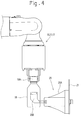
- Authority
- EP
- European Patent Office
- Prior art keywords
- isolator
- air
- decontamination chamber
- opening
- chamber
- Prior art date
- Legal status (The legal status is an assumption and is not a legal conclusion. Google has not performed a legal analysis and makes no representation as to the accuracy of the status listed.)
- Withdrawn
Links
- 238000005202 decontamination Methods 0.000 claims abstract description 155
- 230000003588 decontaminative effect Effects 0.000 claims abstract description 155
- 230000003247 decreasing effect Effects 0.000 claims description 10
- 239000003153 chemical reaction reagent Substances 0.000 abstract description 11
- 210000004027 cell Anatomy 0.000 description 51
- 238000012545 processing Methods 0.000 description 26
- 238000004806 packaging method and process Methods 0.000 description 17
- 238000004519 manufacturing process Methods 0.000 description 16
- 210000004748 cultured cell Anatomy 0.000 description 10
- 238000000034 method Methods 0.000 description 9
- 239000000356 contaminant Substances 0.000 description 8
- 239000007788 liquid Substances 0.000 description 8
- 230000008569 process Effects 0.000 description 8
- 238000010586 diagram Methods 0.000 description 7
- 238000002360 preparation method Methods 0.000 description 7
- 238000012546 transfer Methods 0.000 description 7
- MHAJPDPJQMAIIY-UHFFFAOYSA-N Hydrogen peroxide Chemical compound OO MHAJPDPJQMAIIY-UHFFFAOYSA-N 0.000 description 6
- 238000004113 cell culture Methods 0.000 description 6
- 239000007789 gas Substances 0.000 description 6
- 239000002699 waste material Substances 0.000 description 6
- 230000008859 change Effects 0.000 description 4
- 238000011109 contamination Methods 0.000 description 4
- 238000012258 culturing Methods 0.000 description 4
- LFQSCWFLJHTTHZ-UHFFFAOYSA-N Ethanol Chemical compound CCO LFQSCWFLJHTTHZ-UHFFFAOYSA-N 0.000 description 3
- 239000001963 growth medium Substances 0.000 description 3
- 238000000926 separation method Methods 0.000 description 3
- CURLTUGMZLYLDI-UHFFFAOYSA-N Carbon dioxide Chemical compound O=C=O CURLTUGMZLYLDI-UHFFFAOYSA-N 0.000 description 2
- OSVXSBDYLRYLIG-UHFFFAOYSA-N dioxidochlorine(.) Chemical compound O=Cl=O OSVXSBDYLRYLIG-UHFFFAOYSA-N 0.000 description 2
- 239000003814 drug Substances 0.000 description 2
- 230000007246 mechanism Effects 0.000 description 2
- 238000010899 nucleation Methods 0.000 description 2
- 230000009467 reduction Effects 0.000 description 2
- 238000005406 washing Methods 0.000 description 2
- 241000894006 Bacteria Species 0.000 description 1
- 239000004155 Chlorine dioxide Substances 0.000 description 1
- IAYPIBMASNFSPL-UHFFFAOYSA-N Ethylene oxide Chemical compound C1CO1 IAYPIBMASNFSPL-UHFFFAOYSA-N 0.000 description 1
- CBENFWSGALASAD-UHFFFAOYSA-N Ozone Chemical compound [O-][O+]=O CBENFWSGALASAD-UHFFFAOYSA-N 0.000 description 1
- 230000009471 action Effects 0.000 description 1
- 238000004378 air conditioning Methods 0.000 description 1
- 239000001569 carbon dioxide Substances 0.000 description 1
- 229910002092 carbon dioxide Inorganic materials 0.000 description 1
- 235000019398 chlorine dioxide Nutrition 0.000 description 1
- 238000005138 cryopreservation Methods 0.000 description 1
- 238000007599 discharging Methods 0.000 description 1
- 229940079593 drug Drugs 0.000 description 1
- 235000013601 eggs Nutrition 0.000 description 1
- 239000004744 fabric Substances 0.000 description 1
- 238000003780 insertion Methods 0.000 description 1
- 230000037431 insertion Effects 0.000 description 1
- 238000012986 modification Methods 0.000 description 1
- 230000004048 modification Effects 0.000 description 1
- 239000003755 preservative agent Substances 0.000 description 1
- 230000002335 preservative effect Effects 0.000 description 1
- 230000001172 regenerating effect Effects 0.000 description 1
- 230000002123 temporal effect Effects 0.000 description 1
- 238000010257 thawing Methods 0.000 description 1
- 239000012780 transparent material Substances 0.000 description 1
- 238000011179 visual inspection Methods 0.000 description 1
Images






Classifications
-
- B—PERFORMING OPERATIONS; TRANSPORTING
- B01—PHYSICAL OR CHEMICAL PROCESSES OR APPARATUS IN GENERAL
- B01L—CHEMICAL OR PHYSICAL LABORATORY APPARATUS FOR GENERAL USE
- B01L1/00—Enclosures; Chambers
- B01L1/02—Air-pressure chambers; Air-locks therefor
- B01L1/025—Environmental chambers
-
- C—CHEMISTRY; METALLURGY
- C12—BIOCHEMISTRY; BEER; SPIRITS; WINE; VINEGAR; MICROBIOLOGY; ENZYMOLOGY; MUTATION OR GENETIC ENGINEERING
- C12M—APPARATUS FOR ENZYMOLOGY OR MICROBIOLOGY; APPARATUS FOR CULTURING MICROORGANISMS FOR PRODUCING BIOMASS, FOR GROWING CELLS OR FOR OBTAINING FERMENTATION OR METABOLIC PRODUCTS, i.e. BIOREACTORS OR FERMENTERS
- C12M37/00—Means for sterilizing, maintaining sterile conditions or avoiding chemical or biological contamination
-
- B—PERFORMING OPERATIONS; TRANSPORTING
- B01—PHYSICAL OR CHEMICAL PROCESSES OR APPARATUS IN GENERAL
- B01L—CHEMICAL OR PHYSICAL LABORATORY APPARATUS FOR GENERAL USE
- B01L1/00—Enclosures; Chambers
-
- F—MECHANICAL ENGINEERING; LIGHTING; HEATING; WEAPONS; BLASTING
- F24—HEATING; RANGES; VENTILATING
- F24F—AIR-CONDITIONING; AIR-HUMIDIFICATION; VENTILATION; USE OF AIR CURRENTS FOR SCREENING
- F24F7/00—Ventilation
- F24F7/04—Ventilation with ducting systems, e.g. by double walls; with natural circulation
- F24F7/06—Ventilation with ducting systems, e.g. by double walls; with natural circulation with forced air circulation, e.g. by fan positioning of a ventilator in or against a conduit
Definitions
- the present invention relates to a cell treatment apparatus that includes an isolator for cell treatment.
- the aforementioned cell treatment apparatus includes, within a housing, an isolator that maintains thereinside in aseptic conditions and includes a mounting device such as gloves or a suit that is operated by an operator from the outside, a pass box, through which a culture vessel or the like is carried into the isolator, a clean box that forms an inner space for covering an insertion opening of the mounting device of the isolator or an opening and closing door, through which an article is carried into the pass box, and an air-lock chamber located on an inlet-side of the clean box that allows an article for cell treatment to be carried into the clean box in a state shut off from the outside (for example, Patent Literature 1).
- a mounting device such as gloves or a suit that is operated by an operator from the outside
- a pass box through which a culture vessel or the like is carried into the isolator
- a clean box that forms an inner space for covering an insertion opening of the mounting device of the isolator or an opening and closing door, through which an article is carried into the
- Patent Literature 1 JP 2014-198079 A (see Fig. 2 )
- Patent Literature 1 it is necessary to install in the housing the clean box having such a large space as to enable the operator to enter the apparatus and operate a variety of containers within the isolator using the mounting device.
- a cell treatment apparatus includes: an isolator that has an inner space maintained in aseptic conditions and is configured to treat cells in the inner space; a pass box that is configured to carry an article for use in treatment of cells in the inside of the isolator into the inside of the isolator; the pass box including a clean bench chamber and a decontamination chamber, the clean bench chamber having an opening and closing door and being configured to decontaminate the article carried thereinto through an opening formed by opening the opening and closing door, the decontamination chamber having a decontamination capability and an inner space and being configured to be able to carry the article from the clean bench chamber into the inner space of the decontamination chamber from the clean bench chamber and carry the article into the inside of the isolator.
- the cell treatment apparatus may be configured so that the isolator includes an air supply unit that supplies air thereinto, the decontamination chamber includes an air supply unit that supplies air thereinto, the clean bench chamber includes a decontamination chamber opening that is openable and closable to carry the article into the decontamination chamber therethrough, the decontamination chamber includes an isolator opening that is openable and closable to carry the article into the isolator therethrough, and air flows from the decontamination chamber into the clean bench chamber through the decontamination chamber opening during it is opened, or air flows from the isolator into the decontamination chamber through the isolator opening during it is opened.
- the cell treatment apparatus may be configured so that the clean bench chamber includes a decontamination chamber opening that is openable and closable to carry the article into the decontamination chamber therethrough, the decontamination chamber includes an air supply unit that supplies air thereinto and an air exhaust unit that exhausts air therefrom to the outside, and an isolator opening that is openable and closable to carry the article into the isolator therethrough, the supply of air into the decontamination chamber is maintained during the isolator opening is closed and the decontamination chamber opening is opened, and air supplied into the decontamination chamber flows toward the clean bench chamber through the decontamination chamber opening by stopping the exhaust of air from the decontamination chamber to the outside or decreasing the amount of air exhausted from the decontamination chamber to the outside.
- the cell treatment apparatus may be configured so that the clean bench chamber includes a decontamination chamber opening that is openable and closable to carry the article into the decontamination chamber therethrough, the decontamination chamber includes an air supply unit that supplies air thereinto and an air exhaust unit that exhausts air therefrom to the outside, and an isolator opening that is openable and closable to carry the article into the isolator therethrough, the isolator includes an air supply unit that supplies air thereinto and an air exhaust unit that exhausts air therefrom to the outside, the exhaust of air from the isolator to the outside and the supply of air into the decontamination chamber are stopped or the amount of air exhausted from the isolator to the outside and the amount of air supplied into the decontamination chamber are decreased during the decontamination chamber opening is closed and the isolator opening is opened, and air supplied into the isolator flows toward the decontamination chamber through the isolator opening by maintaining the supply of air into the isolator and the exhaust of air from the
- the cell treatment apparatus may be configured so that each of the isolator opening and the decontamination chamber opening has such a height as to allow an article having a largest dimension among the articles to pass therethrough.
- production apparatus an apparatus to produce cultured cell products (hereinafter, referred to as production apparatus) that is an example of a cell treatment apparatus of the present invention will be described.
- the left and right directions correspond to the state shown in Fig. 1 and Fig. 2
- the front and rear directions correspond to the state of Fig. 2 where the lower side corresponds to the "front” and the upper side corresponds to the "rear” (the directions are shown also in Fig. 2 ).
- Fig. 1 to Fig. 3 show the production apparatus of this embodiment.
- the production apparatus includes a plurality of incubators 2, a horizontally elongated isolator 3, and a plurality (two in Fig. 2 ) of pass boxes 4.
- An incubator 2 houses a cell culture vessel (hereinafter referred to a culture vessel) 1 that is an article.
- the isolator 3 is capable of having its inside maintained in aseptic conditions and treats the culture vessel 1 transferred from the incubator 2.
- the pass boxes 4 are configured to be capable of carrying a reagent container into the isolator 3, in which the reagent container contains an article and a reagent necessary for subdividing and putting-in of cells cultured in the culture vessel 1.
- a HYPERFlask manufactured by Corning Incorporated capable of culturing cells in multilayers, for example, can be used.
- Each part is controlled by a control device X schematically shown in Fig. 1 .
- the control device X may be provided integrally with the production apparatus or may be a separate body (such as a personal computer) connected to the production apparatus in a wired or wireless manner. Further, it is also possible to provide the control device X integrally with the production apparatus and provide only an operation section of the control device X that is operated by an operator (such as a tablet terminal) as a separate body from the production apparatus.
- the incubators 2 are provided in total in a state of being vertically stacked in two stages as shown in Fig. 1 , at three points in total including one point at the left end of the isolator 3 and two points in the left end part behind the isolator 3, as shown in Fig. 2 .
- Two incubators 2 in the upper stage and the lower stage have the same configuration, and each of the incubators 2 is provided with racks (not shown) capable of housing a large number of the culture vessels 1 within a casing 2A.
- the casing 2A has a box shape with one lateral side opening so that the culture vessels 1 can be taken in and out through the lateral side.
- Two doors 2B and 2C configured to close the opening on the one lateral side of the casing 2A are attached to the casing 2A so as to be freely openable.
- the inside door 2C is formed with a transparent material, so that the number of the culture vessels 1 housed therein and the state of the cell culture can be checked only by opening the outside door 2B while the opening is closed by the inside door 2C.
- carbon dioxide gas for adjusting the culture atmosphere is configured to be supplied into the incubators 2.
- the culture vessels 1 housed on the racks inside the incubators 2 are configured to be delivered onto a plurality of mounting tables 5 provided in the isolator 3 by a delivery mechanism, which is not shown. Six units of the mounting tables 5, which is the same number as the number of the incubators 2, are arranged corresponding to the incubators 2.
- the isolator 3 is horizontally elongated (in this embodiment, it is rectangular in planer view), where one set (two units on the upper and lower sides) of incubators 2 is located on the short side of the isolator 3 (in this embodiment, the left side), and a plurality of sets (in this embodiment, two sets of incubators 2) are located on the longitudinal side (in this embodiment, the rear side).
- This configuration can reduce the size of the production apparatus without decreasing the number of cultured cells.
- the isolator 3 includes an observation section 8, a processing section 13, and an outlet 14.
- the observation section 8 includes two first robot arms 6 and 7 configured to move the culture vessels 1 to an observation position so that the degree of growth in the culture vessels 1 taken out of the incubators 2 is checked.
- the processing section 13 is provided continuously with the observation section 8.
- the processing section 13 includes three second robot arms 10, 11, and 12.
- the second robot arms 10, 11, and 12 are configured to transfer cells in the culture vessels 1 that have a specified number of cells out of the culture vessels 1 observed in the observation section 8 into a large number of product containers 9 (such as vial containers, see the enlarged view of Fig. 1 ), which are articles carried in from the pass boxes 4.
- the outlet 14 is configured to allow the large number of product containers 9 into which the cells have been transferred to be taken out therethrough.
- a large number of work gloves (not shown) that allow the operator to perform operations by putting their hands into the isolator 3 are attached onto the front and rear walls of the isolator 3. As shown in Fig. 2 , the five robot arms 6, 7, 10, 11, and 12 are aligned in a straight line extending in the left and right directions along the longitudinal direction of the isolator 3.
- the first robot arm 6 on the left side corresponds to one set of incubators 2 located on the short side of the isolator 3 (in this embodiment, on the left side) and one set of incubators 2 on the left side out of the sets of incubators 2 located on the longitudinal side (in this embodiment, on the rear side).
- the first robot arm 6 on the left side can handle the culture vessels 1 that are housed in these incubators 2 (the range that can be reached by each robot arm (in planer view) is shown in Fig. 2 with a dashed-double-dotted circle).
- the first robot arm 7 on the right side corresponds to one set of incubators 2 on the right side out of the sets of incubators 2 located on the longitudinal side of the isolator 3.
- the first robot arm 7 on the right side can handle the culture vessels 1 housed in the incubators 2.
- the second robot arm 10 on the left side and the second robot arm 11 in the middle correspond to the pass box 4 on the left side out of the pass boxes 4 located on the longitudinal side of the isolator 3 (in this embodiment, on the rear side).
- the second robot arm 10 on the left side and the second robot arm 11 in the middle can handle reagent containers in which articles and reagents are contained, the reagent containers being to be housed (or having been housed) in the pass box 4.
- the second robot arm 12 on the right side corresponds to the pass box 4 on the right side out of the pass boxes 4 located on the longitudinal side of the isolator 3 (in this embodiment, on the rear side) and a box 22 for carrying out the product containers 9.
- the second robot arm 12 on the right side can handle reagent containers in which articles and reagents are contained, the reagent containers being to be housed (or having been housed) in the pass box 4, and the product containers 9 to be housed in the box 22.
- the five robot arms 6, 7, 10, 11, and 12 are arranged in a positional relationship so as to be capable of passing articles to each other.
- the robot arms 6, 7, 10, 11, and 12 are located within the isolator 3, thereby enabling each of the robot arms 6, 7, 10, 11, and 12 to act on the incubators 2, the isolator 3, the pass boxes 4, and the box 22 according to the purpose.
- the production apparatus of this embodiment it is possible to improve the working efficiency and contribute to mass production of cultured cell products.
- the first robot arms 6 and 7 and the second robot arms 10, 11, and 12 in this embodiment have the same configuration. Therefore, the description for the first robot arm 6 located at the left end will be applied to the description for each of the first robot arm 7, and the second robot arms 10, 11, and 12.
- the first robot arm 6 is constituted by articulated robot arm.
- the first robot arm 6 includes a fixed part 6A fixed to a base member 15 of the isolator 3, a base part 6B that is pivotable about the vertical axis at the distal end part of the fixed part 6A, a first arm 6C that is swingable about the horizontal axis at the distal end part of the base part 6B, a second arm 6D that is swingable about the horizontal axis at the distal end part of the first arm 6C, a third arm 6E that is swingable about the horizontal axis at the distal end part of the second arm 6D, and a pair of grips 6F that are attached to the distal end of the third arm 6E so as to be opposed thereto.
- the pair of grips 6F are configured to be capable of moving close to and away from each other.
- the articulated first robot arms 6 and 7 can hold the culture vessels 1 delivered from the incubators 2 using the pair of grips 6F (see Fig. 1 ) and move them to a microscope 16 at the observation position.
- the second robot arms 10, 11, and 12 are configured to hold such as a centrifuge tube 17 and a preparation tank 18 shown in Fig. 1 in addition to the culture vessels 1 so as to be capable of performing various processes.
- the microscope 16 is arranged at the observation position between the two first robot arms 6 and 7.
- the microscope 16 By arranging the microscope 16 as above, it is possible to move the culture vessels 1 to the microscope 16 using the first robot arm 6 on the left side so as to observe the cells, and as a result of the observation, it is possible to hold the culture vessels 1 that have been determined to have a specified number of cells so as to rapidly move them to the processing section 13 side, using the first robot arm 7 on the right side.
- the first robot arm 6 on the left side mainly performs the operation to move the culture vessels 1 to the microscope 16, and the first robot arm 7 on the right side performs the operation to move the culture vessels 1 that have been determined to have a specified number of cells toward the processing section 13 side. These operations by the first robot arms 6 and 7 can accelerate the operation speed.
- the determination on whether the culture vessels 1 have a specified number of cells may be made by counting the number of cells by visual inspection of the operator (human) of the production apparatus or may be made by the control device based on the number of cells calculated by analyzing an image captured by a camera so as to calculate the number of cells.
- the culture vessels 1 that are delivered from the incubator 2 located opposed to the first robot arm 7 on the right side are held by the first robot arm 7 on the right side to be moved to the microscope 16. Further, a microscope 25 is provided also in the processing section 13. The object observed by the microscope 25 is held by the second robot arm 12 on the right end to be moved.
- the culture vessels 1 after the observation are conveyed not only by being directly passed from the first robot arm 7 on the right side to the second robot arms 10 arranged at the left end of the processing section 13.
- the culture vessels 1 are conveyed by a conveying apparatus 19 to a position where the second robot arm 10 at the left end of the processing section 13 or the second robot arm 11 arranged at horizontal center of the processing section 13 can grip them.
- the conveying apparatus 19 is provided along the front sidewall of the isolator 3 and is set to a length that allows the conveying apparatus 19 to convey them from the right end part of the observation section 8 of the isolator 3 to the horizontal center of the processing section 13. Accordingly, when the first robot arm 7 on the right side passes the culture vessels 1 after the observation to the conveyance starting end part of the conveying apparatus 19, the conveying apparatus 19 conveys the culture vessels 1 to the position where one of the two second robot arms 10 and 11 can grip them.
- the conveying apparatus 19 is provided corresponding to at least one robot arm (in this embodiment, the first robot arm 7) located in the observation section 8 and a plurality of robot arms (in this embodiment, the two second robot arms 10 and 11) located in the processing section 13.
- the first robot arm 7 can directly deliver the articles to the second robot arm 10.
- the conveying apparatus 19 can deliver the articles to the first robot arm 7 and the third robot arm 11 between which direct delivery of the articles is impossible. Therefore, even in the case where the articles cannot be delivered from the first robot arm 7 to the third robot arm 11 via the second robot arm 10 due to the second robot arm 10 being in operation, the articles can be delivered from the first robot arm 7 to the third robot arm 11 via the conveying apparatus 19. Therefore, the articles can be conveyed in parallel (via a plurality of routes) within the isolator 3. Accordingly, the working efficiency within the isolator 3 can be improved, and thus the productivity can be improved.
- an immovable fixed auxiliary arm 20 is provided at a position in the vicinity of each of the second robot arms 10, 11, and 12 and below each of the second robot arms 10, 11, and 12.
- the auxiliary arm 20 includes a fixed part 20A fixed to a fixing member 21, and a pair of grips 20B (in Fig. 4 , only the grip 20B on the front side is shown) attached so as to be capable of moving close to and away from the fixed part 20A.
- a cap 18A of the preparation tank 18 can be opened or closed by the single second robot arm 10, 11, or 12.
- a program to open and close screw caps that are provided on a plurality of types of containers is stored in the second robot arms 10, 11, and 12, so that the second robot arms 10, 11, and 12 can open and close the screw caps provided on the plurality of types of containers. Therefore, it is not necessary to unify the types of containers into the same type, and thus the production apparatus of cultured cell products can be easily achieved. Also in the first robot arms 6 and 7, such a program may be stored.
- the two pass boxes 4 are provided to be continuous with the rear wall of the processing section 13.
- One (on the left side) of the pass boxes 4 is arranged so that the articles can be carried therein passing through between the second robot arm 10 located at the left end and the second robot arm 11 located at the center.
- Examples of the articles include a plurality of types of containers including the product containers 9, the culture vessels 1, and the centrifuge tube 17, and the preparation tank 18 that is a container in which drugs are put.
- the other (on the right side) of the pass boxes 4 is arranged so that the articles are carried to the second robot arm 12 located at the right end.
- the isolator 3 is horizontally elongated, in which the plurality (in this embodiment, two) of pass boxes 4 are located on the longitudinal side of the isolator 3 (in this embodiment, on the rear side).
- This configuration can reduce the size of the production apparatus without limiting the amount of articles to be carried into the isolator 3.
- the opening of the outlet 14 is configured to have a size such that the second robot arm 12 located at the right end can easily enter therethrough.
- the outlet 14 is provided with a freely openable electric shutter (not shown) and is provided continuously with the box 22 that forms a space in which the product containers 9 moved through the outlet 14 to the outside of the isolator 3 are kept for a while.
- the processing section 13 includes a first transfer processing unit, a separation processing unit, and a second transfer unit.
- the first transfer processing unit is configured to transfer a cell-containing liquid housed in the culture vessels 1 received from the first robot arm 7 into the centrifuge tube 17 using the second robot arm 10.
- the separation processing unit is configured to separate the cells and a liquid portion by subjecting the centrifuge tube 17 to a centrifuge 26 using the second robot arm 10.
- the second transfer unit is configured to transfer a specified number of cells within the centrifuge tube 17 into a large number of the product containers 9 while a preservative solution (cryopreservation solution) is put into the centrifuge tube 17 after removing at least part of the liquid portion separated in the separation processing unit from the centrifuge tube 17, using the second robot arm 10.
- the term "cell-containing liquid” simply means a "liquid containing cells” and is not limited to a liquid in a specific state.
- the processing section 13 includes a medium-replacing unit configured to replace the culture medium within the culture vessels 1 taken out of the incubators 2 using the first robot arm 7.
- the medium-replacing unit is configured to open the caps of the culture vessels 1 received by the second robot arm 10 from the first robot arm 7, to dispose of the culture medium within the culture vessels 1, to supply another culture medium into the cell culture vessels 1, to put the caps thereon, and to return them to the first robot arm 7.
- the processing section 13 configured as above is capable of performing a first process of thawing frozen cells and seeding them, a second process (passage process) of collecting the cells and seeding them on a large number of culture vessels, and a third process of collecting the cultured cells in the culture vessels after the passage process, subdividing the collected cells, transferring them into the product containers 9, and carrying them out through the outlet 14.
- a large-size waste disposal part 23 for disposal of large-size waste products such as the centrifuge tube 17 and the preparation tank 18, in addition to the cell culture vessels 1, which become unnecessary during the aforementioned processes.
- a small-size waste disposal part 24 for disposal of small size waste products such as pipette tips (suction openings mounted to pipettes, not shown).
- the two pass boxes 4 have the same configuration.
- Each of the pass boxes 4 includes a first box 27 that constitutes a clean bench chamber R1 for carrying containers from outside thereinto, and a second box 28 that constitutes a decontamination chamber R2 for carrying containers from the clean bench chamber R1 into the isolator 3.
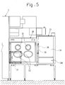
- each of inner side surfaces respectively opposed to the second boxes 28 (only one of them are shown in Fig. 5 ) has a large number of (four in Fig. 5 ) glove ports G1 and G2.
- a rack may be provided in an upper space of each of the first box 27 and the second box 28 so as to temporarily place thereon articles carried into the inside, which enables efficient container carrying-in operation from the clean bench chamber R1 to the decontamination chamber R2, and from the decontamination chamber R2 to the isolator 3.
- pipes for transferring a washing liquid or the like for use in the isolator 3 to the isolator 3, and pipes for discharging the washing liquid used in the isolator 3 are arranged in the pass box 4.
- the clean bench chamber R1 includes a first air supply unit 29 that is constituted by an air supply fan for supplying air into the inside thereof.
- the decontamination chamber R2 includes a second air supply unit 30 that is constituted by an air supply fan for supplying air into the inside thereof, and a second air exhaust unit 31 that is constituted by an air exhaust fan for exhausting air to the outside.
- the isolator 3 includes a third air supply unit 32 that is constituted by an air supply fan for supplying air into the inside thereof, and a third air exhaust unit 33 that is constituted by an air exhaust fan for exhausting air to the outside.
- the isolator 3 and the decontamination chamber R2 is configured so that hydrogen peroxide gas is supplied thereinto from a hydrogen peroxide gas generating device (not shown).
- the description herein refers to hydrogen peroxide gas, but alternatively, ozone, chlorine dioxide gas, ethylene oxide gas or the like may be supplied.
- shutters 34 (only one of them is shown in Fig. 5 ) as opening and closing doors of sliding type that can slide in the vertical direction are each provided on one lateral side of each of the two opposed clean bench chambers R1.
- Each of the shutters 34 is configured to change the opening degree of an opening 34K formed on a lower side.
- the opening 34K is set to be substantially one fourth of an area when the shutter 34 is in the fully opened position.
- Containers are manually passed through the opening 34K from the outside of the clean bench chamber R1 into the clean bench chamber R1, where containers which cannot be decontaminated are decontaminated with alcohol within the decontamination chamber R2. Decontamination treatment is performed in this way.
- containers which can be decontaminated in the decontamination chamber R2 are not decontaminated in the clean bench chamber R1, but are carried into the decontamination chamber R2 where decontamination is performed.
- the size of a space for performing the operations in the clean bench chamber R1 is enough if it allows a largest size of containers to be subjected to decontamination treatment.
- the opening 34K is formed not on the one lateral side of the opposed clean bench chambers R1, but on one end side in the longitudinal direction of the pass box 4 (right end in Figures) in order to be able to illustrate flows of air.
- the clean bench chamber R1 includes a decontamination chamber opening 35A that is openable and closable for carrying containers into the decontamination chamber R2.
- This decontamination chamber opening 35A can be opened and closed by moving up and down a first cover 35 using an air cylinder 36.
- the first cover 35 is formed by a plate-shaped member having a substantially square shape, and is vertically movably supported to a side wall 28A of the second box 28 by a guide mechanism (not shown).
- the air cylinder 36 has a cylinder tube 36B that is fixed to the side wall 28A of the second box 28 with a proximal end of the cylinder tube 36B upwardly oriented, and has a piston rod 36A that is connected to a lower end of the first cover 35 with a distal end of the piston rod 36A oriented downwardly.
- the piston rod 36A of the air cylinder 36 is retracted to slide the first cover 35 upwardly so that the decontamination chamber opening 35A is brought into an opened state (see a two-dot chain line in Fig.
- the decontamination chamber R2 includes an isolator opening 37A that can be opened and closed, through which containers carried from the clean bench chamber R1 into the decontamination chamber R2 is carried into the isolator 3.
- the isolator opening 37A is covered by a second cover 37, which slides in the lateral side to be able to open and close the isolator opening 37A.
- the second cover 37 is formed by a plate-shaped member having a substantially square shape, and includes a pair of left and right handles 37H for opening and closing operation at both ends in the slide direction.
- the second cover 37 is configured so as to be able to move in the lateral direction while having its upper and lower ends supported by a pair of upper and lower guide rails 38 and 39.
- the upper guide rail 38 and the lower guide rail 39 are arranged to oppose to each other in the vertical direction, and are formed respectively by L-shaped members fixed to two adjacent side walls 28B and 28C of the second box 28 constituting the decontamination chamber R2.
- the upper guide rail 38 includes a top plate part 38A fixed to four brackets (only three brackets are shown in Figs.
- a pair of moving bodies 41 are movably provided inside the upper guide rail 38, and an upper end of the second cover 37 is connected to the pair of moving bodies 41.
- Each of the moving bodies 41 includes a pair of bearings 43 that are mounted on the pair of horizontal plate parts 38C and coupled to each other through lateral shafts 42, a spacing member 44 for holding a space between the bearings 43 and having the lateral shafts 42 extending through the spacing member 44, and a pin 45 that extends through the spacing member 44 movably around a vertical axis and is attached to the spacing member 44.
- an upper frame body 46 having a reversed L-shape which is fixed to an upper end of the second cover 37 with screws, is fastened and fixed to the spacing member 44 by the pin 45.
- the second cover 37 can smoothly change its moving direction without deflecting during moving through a curved portion of the upper guide rail 38 since the second cover 37 can smoothly move along the upper guide rail 38 by the rotation of the pair of bearings 43, while rotating around the axis of the pin 45.
- the lower guide rail 39 has a substantially U-shape with its upper end opening, and a pair of left and right rollers 47, which are rotatable around the vertical axis, are provided within the lower guide rail 39.
- the pair of left and right rollers 47 are coupled, rotatably around the vertical axis, to a lower frame body 48 that has a L-shape and is fixed to a lower end of the second cover 37 with screws.
- the second cover 37 can smoothly change its moving direction without deflecting during moving through a curved portion of the lower guide rail 39 since the second cover 37 can smoothly move along the lower guide rail 39 by the rotation of the pair of left and right rollers 47.
- the second cover 37 which is located at a position at which it closes the isolator opening 37A, is shown in solid line
- the second cover 37 which is located at a position at which it opens the isolator opening 37A, is shown in dashed-double-dotted line.
- the reference numeral 49 shown in Fig. 9 represents a stopper member, to which the second cover 37 abuts when it is located at the closing position
- the reference numeral 50 represents a stopper member, to which the second cover 37 abuts when it is located at the opening position.
- Fig. 12a shows the packaging bag 52 just before carrying-in. Specifically, the first cover 35 and the second cover 37 are located at the closing positions, and supplying air by the third air supply unit 32 and exhausting air by the third air exhaust unit 33 are performed within the isolator 3.
- the operator carries the packaging bag 52 with the containers placed therein into the clean bench chamber R1 through the opening 34K. After the carrying in of the packaging bag 52, the operator passes the packaging bag 52 through the opening 34K, and wipes off the outer surface of the packaging bag 52 with alcohol containing cloth to subject the same to the alcohol decontamination. Next, the operator stops exhausting air from the decontamination chamber R2 to the outside, or decrease the amount of air exhausted from the decontamination chamber R2 to the outside from the amount of air exhausted in normal exhausting operation, and thereafter presses a switch (not shown) to locate the first cover 35 at the opening position.
- the two containers 51 are packaged within the packaging bag 52 in aseptic conditions and therefore they are still held in aseptic conditions when they are taken out of the packaging bag 52.
- the operator stops the exhaust of air from the isolator 3 to the outside or decrease the amount of air exhausted from the isolator 3 to the outside to the amount smaller than the amount of air exhausted in normal exhaust operation, and at the same time stops the supply of air to the decontamination chamber R2 or decrease the amount of air supplied to the clean bench chamber R1 to the amount smaller than the amount of air supplied in normal supply operation.
- the operator grabs the handle 37H of the second cover 37 to slidingly move the second cover 37 in the lateral direction to the opening position.
- the supply and exhaust of air is controlled so that air to be supplied to the isolator 3 passes through the isolator opening 37A, flows toward the decontamination chamber R2, and is exhausted to the outside of the decontamination chamber R2.
- air (contaminant) within the decontamination chamber R2 does not intrude into the isolator 3.
- the operator carries the containers 51, which are being held in aseptic conditions, into the isolator 3 through the isolator opening 37A (see Fig. 3a ).
- the operator holds the handle 37H of the second cover 37 to slidingly move the second cover 37 in the lateral direction to the closing position.
- the operator restarts the exhaust of air from the isolator 3 and the supply of air into the decontamination chamber R2, or increase the amount of air exhausted from the isolator 3 to the outside and the amount of air supplied into the decontamination chamber R2, which have been decreased, to the amount of exhausted air and the amount of supplied air in normal operation before the reduction to finish the operation.
- the amount of exhausted air and the amount of supplied air are to be increased or decreased (changed)
- Each of the isolator opening 37A and the decontamination chamber opening 35A has such a height as to allow a container having a largest dimension (herein HYPERFlask manufactured by Corning Incorporated) capable of culturing cells to pass therethrough.
- the opening 34K of the clean bench chamber R1 also has such a height as to allow a container having a largest dimension (herein HYPERFlask manufactured by Corning Incorporated) capable of culturing cells to pass therethrough.
- Such height setting enables the size of each opening to be minimized and air flows to be desirably controlled, while enabling all the kinds of handled containers (articles) to be carried into the respective chambers. As a result, it is possible to more securely avoid occurrence of troubles such as contamination.
- the cell treatment apparatus according to the present invention is not limited to the aforementioned embodiment, and various modifications can be made without departing from the gist of the present invention.
- the isolator 3 is configured to have a horizontally elongated shape as an example, but may be configured to have a square shape or a circular shape. Further, it may be configured to have a bent shape.
- first cover 35 is configured to be movable in the vertical direction and the second cover 37 is configured to be movable in the lateral direction.
- moving direction of each of the first cover 35 and the second cover 37 may be set to any direction.
- the description of the aforementioned embodiment was made for the apparatus to produce cultured cell products, which is configured to culture cells and subdivide cultured cells into products.
- the present invention is also applicable to an apparatus to culture cells, which is configured to perform only cell culturing, or applicable to a product manufacturing apparatus, which is configured to subdivide cultured cells into products.
- each of the isolator 3 and the decontamination chamber R2 is provided with an air supply unit and an air exhaust unit.
- the present invention is also applicable to the case where only the air supply unit for supplying air is provided.
- the cell treatment apparatus includes: an isolator 3 configured to treat cells in the inside of the isolator 3 maintained in aseptic conditions; pass boxes 4 configured to carry an article for use in treatment of cells in the inside of the isolator 3 into the inside of the isolator 3, each of the pass boxes 4 including a shutter 34; a clean bench chamber R1 configured to decontaminate the article carried thereinto through an opening 34K formed by opening the shutter 34; and a decontamination chamber R2 that has a decontamination capability and is configured to be able to carry the article from the clean bench chamber R1 into the inside of the decontamination chamber R2 and carry the same into the inside of the isolator 3.
- the openable and closable shutter 34 is opened to carry an article into the clean bench chamber R1 from the outside to operate decontamination treatment from the outside.
- the clean bench chamber R1 has such an inside space as to enable the operation for decontamination treatment from the outside, and the article before carried into the decontamination chamber R2 is subjected to decontamination treatment so that it is possible to decontaminate in aseptic conditions the article carried from the outside, while suppressing enlargement of the size of the apparatus itself.
- the temporal placement of the article, which has been decontaminated in the clean bench chamber R1, in the decontamination chamber R2 enables the article to be carried into the isolator 3 while maintaining the decontaminated conditions. Whereby, it is possible to suppress contamination inside of the isolator 3.
- the cell treatment apparatus may be configured so that the isolator 3 includes an air supply unit 32 that supplies air thereinto, the decontamination chamber R2 includes an air supply unit 30 that supplies air thereinto, and the clean bench chamber R1 includes a decontamination chamber opening 35A that is openable and closable to carry the article into the decontamination chamber R2 therethrough, in which air flows from the decontamination chamber R2 into the clean bench chamber R1 through the decontamination chamber opening 35A during it is opened, or air flows from the isolator 3 into the decontamination chamber R2 through the isolator opening 37A during it is opened.
- the cell treatment apparatus may be configured so that the clean bench chamber R1 includes a decontamination chamber opening 35A that is openable and closable to carry the article into the decontamination chamber R2 therethrough, the decontamination chamber R2 includes air supply and exhaust units 30 and 31 (air supply unit 30, air exhaust unit 31) that supplies air thereinto and exhausts air therefrom to the outside, and an isolator opening 37A that is openable and closable to carry the article into the isolator 3 therethrough, in which the supply of air into the decontamination chamber R2 is maintained during the isolator opening 37A is closed and the decontamination chamber opening 35A is opened, and air supplied to the decontamination chamber R2 flows toward the clean bench chamber R1 through the decontamination chamber opening 35A by stopping the exhaust of air from the decontamination chamber R2 to the outside or decreasing the amount of air exhausted from the decontamination chamber R2 to the outside.
- the decontamination chamber R2 includes air supply and exhaust units 30 and 31 (air supply unit 30, air exhaust unit 31)
- air supplied into the decontamination chamber R2 flows toward the clean bench chamber R1 through the decontamination chamber opening 35A so that it is possible to suppress contaminant within the clean bench chamber R1 from intruding into the decontamination chamber R2.
- the cell treatment apparatus may be configured so that the clean bench chamber R1 includes a decontamination chamber opening 35A that is openable and closable to carry the article into the decontamination chamber R2 therethrough, the decontamination chamber R2 includes air supply and exhaust units 30 and 31 (air supply unit 30, air exhaust unit 31) that supplies air thereinto and exhausts air therefrom to the outside, and an isolator opening 37A that is openable and closable to carry the article into the isolator 3 therethrough, the isolator 3 includes air supply and exhaust units 32 and 33 (air supply unit 32, air exhaust unit 33) that supplies air thereinto and exhausts air therefrom to the outside, in which the exhaust of air from the isolator 3 to the outside and the supply of air into the decontamination chamber R2 are stopped or the amount of air exhausted from the isolator 3 to the outside and the amount of air supplied into the decontamination chamber R2 are decreased during the decontamination chamber opening 35A is closed and the isolator opening 37A is opened,
- air supplied into the isolator 3 flows toward the decontamination chamber R2 through the isolator opening 37A so that it is possible to suppress contaminant within the decontamination chamber R2 from intruding into the isolator 3.
- the cell treatment apparatus may be configured so that each of the isolator opening 37A and the decontamination chamber opening 35A has such a height as to allow an article having a largest dimension among the articles to pass therethrough.
- the isolator opening 37A and the decontamination chamber opening 35A each have such a height as to allow the article having a largest dimension among the articles to pass therethrough in the manner mentioned above can make it possible to limit each opening to a minimum height while all the articles can be passed therethrough, which enables air flows to be desirably controlled and hence occurrence of troubles such as contamination to be more securely avoided.
Landscapes
- Health & Medical Sciences (AREA)
- Chemical & Material Sciences (AREA)
- Engineering & Computer Science (AREA)
- Life Sciences & Earth Sciences (AREA)
- Bioinformatics & Cheminformatics (AREA)
- Organic Chemistry (AREA)
- Wood Science & Technology (AREA)
- Zoology (AREA)
- General Engineering & Computer Science (AREA)
- Chemical Kinetics & Catalysis (AREA)
- Clinical Laboratory Science (AREA)
- Biomedical Technology (AREA)
- Biochemistry (AREA)
- Sustainable Development (AREA)
- General Health & Medical Sciences (AREA)
- Genetics & Genomics (AREA)
- Microbiology (AREA)
- Biotechnology (AREA)
- Molecular Biology (AREA)
- Combustion & Propulsion (AREA)
- Mechanical Engineering (AREA)
- Apparatus Associated With Microorganisms And Enzymes (AREA)
Abstract

Description
- This application claims priority to Japanese Patent Application No.
2015-206192 - The present invention relates to a cell treatment apparatus that includes an isolator for cell treatment.
- In recent years, cell culture is performed using tissues and cells of various sites of human body, fertilized eggs, or the like, and the cultured cells have been put to practical use for regenerative medicine. In the cell culture, it is important to prevent contamination of cells by bacteria or the like during the culture. Therefore, a cell treatment apparatus that enables the culture of cells within a housing having a configuration that can maintain thereinside in aseptic conditions has been already proposed.
- The aforementioned cell treatment apparatus includes, within a housing, an isolator that maintains thereinside in aseptic conditions and includes a mounting device such as gloves or a suit that is operated by an operator from the outside, a pass box, through which a culture vessel or the like is carried into the isolator, a clean box that forms an inner space for covering an insertion opening of the mounting device of the isolator or an opening and closing door, through which an article is carried into the pass box, and an air-lock chamber located on an inlet-side of the clean box that allows an article for cell treatment to be carried into the clean box in a state shut off from the outside (for example, Patent Literature 1).
- Patent Literature 1:
JP 2014-198079 A Fig. 2 ) - In the aforementioned configuration of Patent Literature 1, it is necessary to install in the housing the clean box having such a large space as to enable the operator to enter the apparatus and operate a variety of containers within the isolator using the mounting device. In addition, it is necessary to have a configuration enabling all the chambers of the housing to be decontaminated in order to enable the operator to enter the clean box. Consequently, there is a disadvantage of increasing the entire size of the cell treatment apparatus.
- In view of the above circumstances, it is an object of the present invention to provide a cell treatment apparatus that can suppress enlargement of the size of the apparatus itself.
- A cell treatment apparatus according to the present invention includes: an isolator that has an inner space maintained in aseptic conditions and is configured to treat cells in the inner space; a pass box that is configured to carry an article for use in treatment of cells in the inside of the isolator into the inside of the isolator; the pass box including a clean bench chamber and a decontamination chamber, the clean bench chamber having an opening and closing door and being configured to decontaminate the article carried thereinto through an opening formed by opening the opening and closing door, the decontamination chamber having a decontamination capability and an inner space and being configured to be able to carry the article from the clean bench chamber into the inner space of the decontamination chamber from the clean bench chamber and carry the article into the inside of the isolator.
- The cell treatment apparatus according to the present invention may be configured so that the isolator includes an air supply unit that supplies air thereinto, the decontamination chamber includes an air supply unit that supplies air thereinto, the clean bench chamber includes a decontamination chamber opening that is openable and closable to carry the article into the decontamination chamber therethrough, the decontamination chamber includes an isolator opening that is openable and closable to carry the article into the isolator therethrough, and air flows from the decontamination chamber into the clean bench chamber through the decontamination chamber opening during it is opened, or air flows from the isolator into the decontamination chamber through the isolator opening during it is opened.
- The cell treatment apparatus according to the present invention may be configured so that the clean bench chamber includes a decontamination chamber opening that is openable and closable to carry the article into the decontamination chamber therethrough, the decontamination chamber includes an air supply unit that supplies air thereinto and an air exhaust unit that exhausts air therefrom to the outside, and an isolator opening that is openable and closable to carry the article into the isolator therethrough, the supply of air into the decontamination chamber is maintained during the isolator opening is closed and the decontamination chamber opening is opened, and air supplied into the decontamination chamber flows toward the clean bench chamber through the decontamination chamber opening by stopping the exhaust of air from the decontamination chamber to the outside or decreasing the amount of air exhausted from the decontamination chamber to the outside.
- The cell treatment apparatus according to the present invention may be configured so that the clean bench chamber includes a decontamination chamber opening that is openable and closable to carry the article into the decontamination chamber therethrough, the decontamination chamber includes an air supply unit that supplies air thereinto and an air exhaust unit that exhausts air therefrom to the outside, and an isolator opening that is openable and closable to carry the article into the isolator therethrough, the isolator includes an air supply unit that supplies air thereinto and an air exhaust unit that exhausts air therefrom to the outside, the exhaust of air from the isolator to the outside and the supply of air into the decontamination chamber are stopped or the amount of air exhausted from the isolator to the outside and the amount of air supplied into the decontamination chamber are decreased during the decontamination chamber opening is closed and the isolator opening is opened, and air supplied into the isolator flows toward the decontamination chamber through the isolator opening by maintaining the supply of air into the isolator and the exhaust of air from the decontamination chamber to the outside.
- The cell treatment apparatus according to the present invention may be configured so that each of the isolator opening and the decontamination chamber opening has such a height as to allow an article having a largest dimension among the articles to pass therethrough.
-
-
Fig. 1 is a front view of an apparatus to produce cultured cell products of the present invention. -
Fig. 2 is a plan view of the aforementioned production apparatus. -
Fig. 3 is a view of the aforementioned production apparatus as seen from the outlet side. -
Fig. 4 is an explanatory diagram showing the state immediately before a vessel cap is opened by a robot arm. -
Fig. 5 is a view as seen from the direction of arrow A-A inFig. 2 . -
Fig. 6 is a cross sectional view taken along line B-B inFig. 2 . -
Fig. 7 is a cross sectional view taken along line C-C inFig. 2 . -
Fig. 8 is a plan view showing a door slide structure included in a decontamination chamber of a pass box. -
Fig. 9 is a view as seen from the direction of arrow D inFig. 8 . -
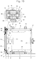
Fig. 10 is a view as seen from the direction of arrow E inFig. 8 . -
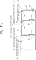
Fig. 11a is an explanatory diagram showing the air conditioning state before a packaging bag with a container therein is put into a clean bench chamber. -
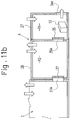
Fig. 11b is an explanatory diagram showing the state where the packaging bag with the container therein has been put in the clean bench chamber. -
Fig. 12a is an explanatory diagram showing the state where the packaging bag with the container therein kept in the clean bench chamber has been put in a decontamination chamber. -
Fig. 12b is an explanatory diagram showing the state where two containers have been taken out from the packaging bag put in the decontamination chamber. -
Fig. 13a is an explanatory diagram showing the state where the container in the decontamination chamber has been put into the isolator. -
Fig. 13b is an explanatory diagram showing the state where an opening for the isolator has been changed into the closed state from the state shown inFig. 13a . - Hereinafter, an apparatus to produce cultured cell products (hereinafter, referred to as production apparatus) that is an example of a cell treatment apparatus of the present invention will be described. In the following description on the front, rear, left, and right directions, the left and right directions correspond to the state shown in
Fig. 1 andFig. 2 , and the front and rear directions correspond to the state ofFig. 2 where the lower side corresponds to the "front" and the upper side corresponds to the "rear" (the directions are shown also inFig. 2 ). -
Fig. 1 to Fig. 3 show the production apparatus of this embodiment. The production apparatus includes a plurality ofincubators 2, a horizontallyelongated isolator 3, and a plurality (two inFig. 2 ) ofpass boxes 4. Anincubator 2 houses a cell culture vessel (hereinafter referred to a culture vessel) 1 that is an article. Theisolator 3 is capable of having its inside maintained in aseptic conditions and treats the culture vessel 1 transferred from theincubator 2. Thepass boxes 4 are configured to be capable of carrying a reagent container into theisolator 3, in which the reagent container contains an article and a reagent necessary for subdividing and putting-in of cells cultured in the culture vessel 1. As the culture vessel 1, a HYPERFlask (manufactured by Corning Incorporated) capable of culturing cells in multilayers, for example, can be used. Each part is controlled by a control device X schematically shown inFig. 1 . The control device X may be provided integrally with the production apparatus or may be a separate body (such as a personal computer) connected to the production apparatus in a wired or wireless manner. Further, it is also possible to provide the control device X integrally with the production apparatus and provide only an operation section of the control device X that is operated by an operator (such as a tablet terminal) as a separate body from the production apparatus. - Six units of the
incubators 2 are provided in total in a state of being vertically stacked in two stages as shown inFig. 1 , at three points in total including one point at the left end of theisolator 3 and two points in the left end part behind theisolator 3, as shown inFig. 2 . Twoincubators 2 in the upper stage and the lower stage have the same configuration, and each of theincubators 2 is provided with racks (not shown) capable of housing a large number of the culture vessels 1 within acasing 2A. Thecasing 2A has a box shape with one lateral side opening so that the culture vessels 1 can be taken in and out through the lateral side. Twodoors casing 2A are attached to thecasing 2A so as to be freely openable. Theinside door 2C is formed with a transparent material, so that the number of the culture vessels 1 housed therein and the state of the cell culture can be checked only by opening theoutside door 2B while the opening is closed by theinside door 2C. Further, carbon dioxide gas for adjusting the culture atmosphere is configured to be supplied into theincubators 2. Further, the culture vessels 1 housed on the racks inside theincubators 2 are configured to be delivered onto a plurality of mounting tables 5 provided in theisolator 3 by a delivery mechanism, which is not shown. Six units of the mounting tables 5, which is the same number as the number of theincubators 2, are arranged corresponding to theincubators 2. - As described above, the
isolator 3 is horizontally elongated (in this embodiment, it is rectangular in planer view), where one set (two units on the upper and lower sides) ofincubators 2 is located on the short side of the isolator 3 (in this embodiment, the left side), and a plurality of sets (in this embodiment, two sets of incubators 2) are located on the longitudinal side (in this embodiment, the rear side). This configuration can reduce the size of the production apparatus without decreasing the number of cultured cells. - The
isolator 3 includes anobservation section 8, aprocessing section 13, and anoutlet 14. Theobservation section 8 includes twofirst robot arms incubators 2 is checked. Theprocessing section 13 is provided continuously with theobservation section 8. Theprocessing section 13 includes threesecond robot arms second robot arms observation section 8 into a large number of product containers 9 (such as vial containers, see the enlarged view ofFig. 1 ), which are articles carried in from thepass boxes 4. Theoutlet 14 is configured to allow the large number ofproduct containers 9 into which the cells have been transferred to be taken out therethrough. A large number of work gloves (not shown) that allow the operator to perform operations by putting their hands into theisolator 3 are attached onto the front and rear walls of theisolator 3. As shown inFig. 2 , the fiverobot arms isolator 3. - With reference to the left and right directions, the
first robot arm 6 on the left side corresponds to one set ofincubators 2 located on the short side of the isolator 3 (in this embodiment, on the left side) and one set ofincubators 2 on the left side out of the sets ofincubators 2 located on the longitudinal side (in this embodiment, on the rear side). Thefirst robot arm 6 on the left side can handle the culture vessels 1 that are housed in these incubators 2 (the range that can be reached by each robot arm (in planer view) is shown inFig. 2 with a dashed-double-dotted circle). Further, thefirst robot arm 7 on the right side corresponds to one set ofincubators 2 on the right side out of the sets ofincubators 2 located on the longitudinal side of theisolator 3. Thefirst robot arm 7 on the right side can handle the culture vessels 1 housed in theincubators 2. - With reference to the left and right directions, the
second robot arm 10 on the left side and thesecond robot arm 11 in the middle correspond to thepass box 4 on the left side out of thepass boxes 4 located on the longitudinal side of the isolator 3 (in this embodiment, on the rear side). Thesecond robot arm 10 on the left side and thesecond robot arm 11 in the middle can handle reagent containers in which articles and reagents are contained, the reagent containers being to be housed (or having been housed) in thepass box 4. - The
second robot arm 12 on the right side corresponds to thepass box 4 on the right side out of thepass boxes 4 located on the longitudinal side of the isolator 3 (in this embodiment, on the rear side) and abox 22 for carrying out theproduct containers 9. Thesecond robot arm 12 on the right side can handle reagent containers in which articles and reagents are contained, the reagent containers being to be housed (or having been housed) in thepass box 4, and theproduct containers 9 to be housed in thebox 22. - As seen from the overlapping of the dashed-double-dotted circles shown in
Fig. 2 , the fiverobot arms - In this way, the
robot arms isolator 3, thereby enabling each of therobot arms incubators 2, theisolator 3, thepass boxes 4, and thebox 22 according to the purpose. Thus, according to the production apparatus of this embodiment, it is possible to improve the working efficiency and contribute to mass production of cultured cell products. - The
first robot arms second robot arms first robot arm 6 located at the left end will be applied to the description for each of thefirst robot arm 7, and thesecond robot arms first robot arm 6 is constituted by articulated robot arm. Thefirst robot arm 6 includes afixed part 6A fixed to abase member 15 of theisolator 3, abase part 6B that is pivotable about the vertical axis at the distal end part of the fixedpart 6A, afirst arm 6C that is swingable about the horizontal axis at the distal end part of thebase part 6B, asecond arm 6D that is swingable about the horizontal axis at the distal end part of thefirst arm 6C, athird arm 6E that is swingable about the horizontal axis at the distal end part of thesecond arm 6D, and a pair ofgrips 6F that are attached to the distal end of thethird arm 6E so as to be opposed thereto. The pair ofgrips 6F are configured to be capable of moving close to and away from each other. The articulatedfirst robot arms incubators 2 using the pair ofgrips 6F (seeFig. 1 ) and move them to amicroscope 16 at the observation position. Thesecond robot arms preparation tank 18 shown inFig. 1 in addition to the culture vessels 1 so as to be capable of performing various processes. - The
microscope 16 is arranged at the observation position between the twofirst robot arms microscope 16 as above, it is possible to move the culture vessels 1 to themicroscope 16 using thefirst robot arm 6 on the left side so as to observe the cells, and as a result of the observation, it is possible to hold the culture vessels 1 that have been determined to have a specified number of cells so as to rapidly move them to theprocessing section 13 side, using thefirst robot arm 7 on the right side. Thefirst robot arm 6 on the left side mainly performs the operation to move the culture vessels 1 to themicroscope 16, and thefirst robot arm 7 on the right side performs the operation to move the culture vessels 1 that have been determined to have a specified number of cells toward theprocessing section 13 side. These operations by thefirst robot arms incubator 2 located opposed to thefirst robot arm 7 on the right side are held by thefirst robot arm 7 on the right side to be moved to themicroscope 16. Further, amicroscope 25 is provided also in theprocessing section 13. The object observed by themicroscope 25 is held by thesecond robot arm 12 on the right end to be moved. - The culture vessels 1 after the observation are conveyed not only by being directly passed from the
first robot arm 7 on the right side to thesecond robot arms 10 arranged at the left end of theprocessing section 13. For example, in the case where thesecond robot arm 10 is in an operation, the culture vessels 1 are conveyed by a conveyingapparatus 19 to a position where thesecond robot arm 10 at the left end of theprocessing section 13 or thesecond robot arm 11 arranged at horizontal center of theprocessing section 13 can grip them. The conveyingapparatus 19 is provided along the front sidewall of theisolator 3 and is set to a length that allows the conveyingapparatus 19 to convey them from the right end part of theobservation section 8 of theisolator 3 to the horizontal center of theprocessing section 13. Accordingly, when thefirst robot arm 7 on the right side passes the culture vessels 1 after the observation to the conveyance starting end part of the conveyingapparatus 19, the conveyingapparatus 19 conveys the culture vessels 1 to the position where one of the twosecond robot arms - The conveying
apparatus 19 is provided corresponding to at least one robot arm (in this embodiment, the first robot arm 7) located in theobservation section 8 and a plurality of robot arms (in this embodiment, the twosecond robot arms 10 and 11) located in theprocessing section 13. Thefirst robot arm 7 can directly deliver the articles to thesecond robot arm 10. The conveyingapparatus 19 can deliver the articles to thefirst robot arm 7 and thethird robot arm 11 between which direct delivery of the articles is impossible. Therefore, even in the case where the articles cannot be delivered from thefirst robot arm 7 to thethird robot arm 11 via thesecond robot arm 10 due to thesecond robot arm 10 being in operation, the articles can be delivered from thefirst robot arm 7 to thethird robot arm 11 via the conveyingapparatus 19. Therefore, the articles can be conveyed in parallel (via a plurality of routes) within theisolator 3. Accordingly, the working efficiency within theisolator 3 can be improved, and thus the productivity can be improved. - In the
processing section 13, three units of thesecond robot arms first robot arms second robot arms Fig. 4 , an immovable fixedauxiliary arm 20 is provided at a position in the vicinity of each of thesecond robot arms second robot arms auxiliary arm 20 includes afixed part 20A fixed to a fixingmember 21, and a pair ofgrips 20B (inFig. 4 , only thegrip 20B on the front side is shown) attached so as to be capable of moving close to and away from thefixed part 20A. InFig. 4 , for example, after the upper end part of thepreparation tank 18 is held by thesecond robot arm grips 20B of theauxiliary arm 20, the lower end part of thepreparation tank 18 is gripped by the pair ofgrips 20B of theauxiliary arm 20. In this way, acap 18A of thepreparation tank 18 can be opened or closed by the singlesecond robot arm second robot arms second robot arms first robot arms - The two
pass boxes 4 are provided to be continuous with the rear wall of theprocessing section 13. One (on the left side) of thepass boxes 4 is arranged so that the articles can be carried therein passing through between thesecond robot arm 10 located at the left end and thesecond robot arm 11 located at the center. Examples of the articles include a plurality of types of containers including theproduct containers 9, the culture vessels 1, and the centrifuge tube 17, and thepreparation tank 18 that is a container in which drugs are put. The other (on the right side) of thepass boxes 4 is arranged so that the articles are carried to thesecond robot arm 12 located at the right end. - As described above, the
isolator 3 is horizontally elongated, in which the plurality (in this embodiment, two) ofpass boxes 4 are located on the longitudinal side of the isolator 3 (in this embodiment, on the rear side). This configuration can reduce the size of the production apparatus without limiting the amount of articles to be carried into theisolator 3. - The opening of the
outlet 14 is configured to have a size such that thesecond robot arm 12 located at the right end can easily enter therethrough. Theoutlet 14 is provided with a freely openable electric shutter (not shown) and is provided continuously with thebox 22 that forms a space in which theproduct containers 9 moved through theoutlet 14 to the outside of theisolator 3 are kept for a while. - The
processing section 13 includes a first transfer processing unit, a separation processing unit, and a second transfer unit. The first transfer processing unit is configured to transfer a cell-containing liquid housed in the culture vessels 1 received from thefirst robot arm 7 into the centrifuge tube 17 using thesecond robot arm 10. The separation processing unit is configured to separate the cells and a liquid portion by subjecting the centrifuge tube 17 to acentrifuge 26 using thesecond robot arm 10. The second transfer unit is configured to transfer a specified number of cells within the centrifuge tube 17 into a large number of theproduct containers 9 while a preservative solution (cryopreservation solution) is put into the centrifuge tube 17 after removing at least part of the liquid portion separated in the separation processing unit from the centrifuge tube 17, using thesecond robot arm 10. In the description of this embodiment, the term "cell-containing liquid" simply means a "liquid containing cells" and is not limited to a liquid in a specific state. - The
processing section 13 includes a medium-replacing unit configured to replace the culture medium within the culture vessels 1 taken out of theincubators 2 using thefirst robot arm 7. The medium-replacing unit is configured to open the caps of the culture vessels 1 received by thesecond robot arm 10 from thefirst robot arm 7, to dispose of the culture medium within the culture vessels 1, to supply another culture medium into the cell culture vessels 1, to put the caps thereon, and to return them to thefirst robot arm 7. - The
processing section 13 configured as above is capable of performing a first process of thawing frozen cells and seeding them, a second process (passage process) of collecting the cells and seeding them on a large number of culture vessels, and a third process of collecting the cultured cells in the culture vessels after the passage process, subdividing the collected cells, transferring them into theproduct containers 9, and carrying them out through theoutlet 14. - Provided at a position close to the
processing section 13 within theobservation section 8 is a large-sizewaste disposal part 23 for disposal of large-size waste products such as the centrifuge tube 17 and thepreparation tank 18, in addition to the cell culture vessels 1, which become unnecessary during the aforementioned processes. Provided at a position close to thebox 22 within theprocessing section 13 is a small-sizewaste disposal part 24 for disposal of small size waste products such as pipette tips (suction openings mounted to pipettes, not shown). - The two
pass boxes 4 have the same configuration. Each of thepass boxes 4 includes afirst box 27 that constitutes a clean bench chamber R1 for carrying containers from outside thereinto, and asecond box 28 that constitutes a decontamination chamber R2 for carrying containers from the clean bench chamber R1 into theisolator 3. As shown inFig. 5 , each of inner side surfaces respectively opposed to the second boxes 28 (only one of them are shown inFig. 5 ) has a large number of (four inFig. 5 ) glove ports G1 and G2. Although not shown, a rack may be provided in an upper space of each of thefirst box 27 and thesecond box 28 so as to temporarily place thereon articles carried into the inside, which enables efficient container carrying-in operation from the clean bench chamber R1 to the decontamination chamber R2, and from the decontamination chamber R2 to theisolator 3. Although not shown, pipes for transferring a washing liquid or the like for use in theisolator 3 to theisolator 3, and pipes for discharging the washing liquid used in theisolator 3 are arranged in thepass box 4. - As shown in
Fig. 11a , the clean bench chamber R1 includes a firstair supply unit 29 that is constituted by an air supply fan for supplying air into the inside thereof. The decontamination chamber R2 includes a secondair supply unit 30 that is constituted by an air supply fan for supplying air into the inside thereof, and a secondair exhaust unit 31 that is constituted by an air exhaust fan for exhausting air to the outside. Theisolator 3 includes a thirdair supply unit 32 that is constituted by an air supply fan for supplying air into the inside thereof, and a third air exhaust unit 33 that is constituted by an air exhaust fan for exhausting air to the outside. Theisolator 3 and the decontamination chamber R2 is configured so that hydrogen peroxide gas is supplied thereinto from a hydrogen peroxide gas generating device (not shown). The description herein refers to hydrogen peroxide gas, but alternatively, ozone, chlorine dioxide gas, ethylene oxide gas or the like may be supplied. - As shown in
Fig. 5 , shutters 34 (only one of them is shown inFig. 5 ) as opening and closing doors of sliding type that can slide in the vertical direction are each provided on one lateral side of each of the two opposed clean bench chambers R1. Each of theshutters 34 is configured to change the opening degree of anopening 34K formed on a lower side. Herein, theopening 34K is set to be substantially one fourth of an area when theshutter 34 is in the fully opened position. Containers are manually passed through theopening 34K from the outside of the clean bench chamber R1 into the clean bench chamber R1, where containers which cannot be decontaminated are decontaminated with alcohol within the decontamination chamber R2. Decontamination treatment is performed in this way. Therefore, containers which can be decontaminated in the decontamination chamber R2 are not decontaminated in the clean bench chamber R1, but are carried into the decontamination chamber R2 where decontamination is performed. The size of a space for performing the operations in the clean bench chamber R1 is enough if it allows a largest size of containers to be subjected to decontamination treatment. InFigs. 11 to Figs. 13 , theopening 34K is formed not on the one lateral side of the opposed clean bench chambers R1, but on one end side in the longitudinal direction of the pass box 4 (right end in Figures) in order to be able to illustrate flows of air. - As shown in
Fig. 7 ,Fig. 11a , andFig. 11b , the clean bench chamber R1 includes adecontamination chamber opening 35A that is openable and closable for carrying containers into the decontamination chamber R2. Thisdecontamination chamber opening 35A can be opened and closed by moving up and down afirst cover 35 using anair cylinder 36. Thefirst cover 35 is formed by a plate-shaped member having a substantially square shape, and is vertically movably supported to aside wall 28A of thesecond box 28 by a guide mechanism (not shown). Theair cylinder 36 has acylinder tube 36B that is fixed to theside wall 28A of thesecond box 28 with a proximal end of thecylinder tube 36B upwardly oriented, and has apiston rod 36A that is connected to a lower end of thefirst cover 35 with a distal end of thepiston rod 36A oriented downwardly. Thepiston rod 36A of theair cylinder 36 is retracted to slide thefirst cover 35 upwardly so that thedecontamination chamber opening 35A is brought into an opened state (see a two-dot chain line inFig. 7 ), and thepiston rod 36A of theair cylinder 36 in the retracted state is extended to slide thefirst cover 35 downwardly, which has been slid upwardly, so that thedecontamination chamber opening 35A is brought into a closed state (see a solid line inFig. 7 ). - As shown in
Fig. 6 ,Fig. 11a , andFig. 11b , the decontamination chamber R2 includes anisolator opening 37A that can be opened and closed, through which containers carried from the clean bench chamber R1 into the decontamination chamber R2 is carried into theisolator 3. Theisolator opening 37A is covered by asecond cover 37, which slides in the lateral side to be able to open and close theisolator opening 37A. Thesecond cover 37 is formed by a plate-shaped member having a substantially square shape, and includes a pair of left andright handles 37H for opening and closing operation at both ends in the slide direction. Thesecond cover 37 is configured so as to be able to move in the lateral direction while having its upper and lower ends supported by a pair of upper andlower guide rails Fig. 8 to Fig. 10 , theupper guide rail 38 and thelower guide rail 39 are arranged to oppose to each other in the vertical direction, and are formed respectively by L-shaped members fixed to twoadjacent side walls second box 28 constituting the decontamination chamber R2. Theupper guide rail 38 includes atop plate part 38A fixed to four brackets (only three brackets are shown inFigs. 11 ) fixed to the twoside walls vertical plate parts 38B extending downward from both ends in the width direction of thetop plate part 38A, and a pair ofhorizontal plate parts 38C that respectively extend from lower ends of the pair ofvertical plate parts 38B to close to each other. A pair of movingbodies 41 are movably provided inside theupper guide rail 38, and an upper end of thesecond cover 37 is connected to the pair of movingbodies 41. Each of the movingbodies 41 includes a pair ofbearings 43 that are mounted on the pair ofhorizontal plate parts 38C and coupled to each other throughlateral shafts 42, a spacingmember 44 for holding a space between thebearings 43 and having thelateral shafts 42 extending through the spacingmember 44, and apin 45 that extends through the spacingmember 44 movably around a vertical axis and is attached to the spacingmember 44. In each of the movingbodies 41, anupper frame body 46 having a reversed L-shape, which is fixed to an upper end of thesecond cover 37 with screws, is fastened and fixed to the spacingmember 44 by thepin 45. Accordingly, thesecond cover 37 can smoothly change its moving direction without deflecting during moving through a curved portion of theupper guide rail 38 since thesecond cover 37 can smoothly move along theupper guide rail 38 by the rotation of the pair ofbearings 43, while rotating around the axis of thepin 45. Thelower guide rail 39 has a substantially U-shape with its upper end opening, and a pair of left andright rollers 47, which are rotatable around the vertical axis, are provided within thelower guide rail 39. The pair of left andright rollers 47 are coupled, rotatably around the vertical axis, to alower frame body 48 that has a L-shape and is fixed to a lower end of thesecond cover 37 with screws. Accordingly, thesecond cover 37 can smoothly change its moving direction without deflecting during moving through a curved portion of thelower guide rail 39 since thesecond cover 37 can smoothly move along thelower guide rail 39 by the rotation of the pair of left andright rollers 47. InFig. 10 , thesecond cover 37, which is located at a position at which it closes theisolator opening 37A, is shown in solid line, and thesecond cover 37, which is located at a position at which it opens theisolator opening 37A, is shown in dashed-double-dotted line. - The
reference numeral 49 shown inFig. 9 represents a stopper member, to which thesecond cover 37 abuts when it is located at the closing position, and thereference numeral 50 represents a stopper member, to which thesecond cover 37 abuts when it is located at the opening position. - The description will be made for the procedures, in which
containers 51 having the above configuration are made to pass through thepass box 4 and carried into theisolator 3. Here, thecontainers 51 are placed in apackaging bag 52. Thepackaging bag 52 with thecontainers 51 placed therein are put in thepass box 4, and thereafter, thecontainers 51 are taken out of thepackaging bag 52, and thecontainers 51 taken out therefrom are carried into theisolator 3.Fig. 12a shows thepackaging bag 52 just before carrying-in. Specifically, thefirst cover 35 and thesecond cover 37 are located at the closing positions, and supplying air by the thirdair supply unit 32 and exhausting air by the third air exhaust unit 33 are performed within theisolator 3. In the same manner as this, supplying air by the secondair supply unit 30 and exhausting air by the secondair exhaust unit 31 are performed within the decontamination chamber R2. Only the supply of air by the firstair supply unit 29 is performed within the clean bench chamber R1. Clean air supplied into the clean bench chamber R1 is exhausted from theopening 34K (which is different in forming position from theopening 34K ofFig. 6 , as described before) to the outside so as to prevent outside air from intruding into the clean bench chamber R1. In Figures other thanFig. 12a , the description for theair supply units air exhaust units 31 and 33 are omitted. - As shown in
Fig. 12b , the state of which is different from the state shown inFig. 12a , the operator carries thepackaging bag 52 with the containers placed therein into the clean bench chamber R1 through theopening 34K. After the carrying in of thepackaging bag 52, the operator passes thepackaging bag 52 through theopening 34K, and wipes off the outer surface of thepackaging bag 52 with alcohol containing cloth to subject the same to the alcohol decontamination. Next, the operator stops exhausting air from the decontamination chamber R2 to the outside, or decrease the amount of air exhausted from the decontamination chamber R2 to the outside from the amount of air exhausted in normal exhausting operation, and thereafter presses a switch (not shown) to locate thefirst cover 35 at the opening position. At this time, air supplied into the decontamination chamber R2 flows toward the clean bench chamber R1 through thedecontamination chamber opening 35A and therefore air (contaminant) within the clean bench chamber R1 does not intrude into the decontamination chamber R2. The operator carries thepackaging bag 52 within the clean bench chamber R1 into the decontamination chamber R2 through thedecontamination chamber opening 35A (seeFig. 13a ) under this circumstance. The operator, after carrying in, locates thefirst cover 35 at the closing position and thereafter restarts the exhaust of air, which has been stopped, or increases the amount of exhausted air, which has been decreased, to the normal amount of air exhausted before the reduction. Subsequently, the operator takes out twocontainers 51 from the packaging bag 52 (seeFig. 13b ). The twocontainers 51 are packaged within thepackaging bag 52 in aseptic conditions and therefore they are still held in aseptic conditions when they are taken out of thepackaging bag 52. Subsequently, the operator stops the exhaust of air from theisolator 3 to the outside or decrease the amount of air exhausted from theisolator 3 to the outside to the amount smaller than the amount of air exhausted in normal exhaust operation, and at the same time stops the supply of air to the decontamination chamber R2 or decrease the amount of air supplied to the clean bench chamber R1 to the amount smaller than the amount of air supplied in normal supply operation. In this state, the operator grabs thehandle 37H of thesecond cover 37 to slidingly move thesecond cover 37 in the lateral direction to the opening position. At this time, the supply and exhaust of air is controlled so that air to be supplied to theisolator 3 passes through theisolator opening 37A, flows toward the decontamination chamber R2, and is exhausted to the outside of the decontamination chamber R2. Thus, air (contaminant) within the decontamination chamber R2 does not intrude into theisolator 3. In this state, the operator carries thecontainers 51, which are being held in aseptic conditions, into theisolator 3 through theisolator opening 37A (seeFig. 3a ). After the carrying-in, the operator holds thehandle 37H of thesecond cover 37 to slidingly move thesecond cover 37 in the lateral direction to the closing position. Then, the operator restarts the exhaust of air from theisolator 3 and the supply of air into the decontamination chamber R2, or increase the amount of air exhausted from theisolator 3 to the outside and the amount of air supplied into the decontamination chamber R2, which have been decreased, to the amount of exhausted air and the amount of supplied air in normal operation before the reduction to finish the operation. When the amount of exhausted air and the amount of supplied air are to be increased or decreased (changed), it is conceivable to change the number of rotation of a motor of each of the air supply fan and the air exhaust fan, or adjust the opening degree of a damper for air flow adjustment. - Each of the
isolator opening 37A and the decontamination chamber opening 35A has such a height as to allow a container having a largest dimension (herein HYPERFlask manufactured by Corning Incorporated) capable of culturing cells to pass therethrough. Theopening 34K of the clean bench chamber R1 also has such a height as to allow a container having a largest dimension (herein HYPERFlask manufactured by Corning Incorporated) capable of culturing cells to pass therethrough. Such height setting enables the size of each opening to be minimized and air flows to be desirably controlled, while enabling all the kinds of handled containers (articles) to be carried into the respective chambers. As a result, it is possible to more securely avoid occurrence of troubles such as contamination. - The cell treatment apparatus according to the present invention is not limited to the aforementioned embodiment, and various modifications can be made without departing from the gist of the present invention.
- The aforementioned embodiment was described by taking, for example, the case where the two
robot arms observation section 8, and the threerobot arms processing section 13. However, it is also possible to apply, to the present invention, the configuration of providing at least one robot arm in theobservation section 8 and providing at least one robot arm in theprocessing section 13. - In the aforementioned embodiment, the
isolator 3 is configured to have a horizontally elongated shape as an example, but may be configured to have a square shape or a circular shape. Further, it may be configured to have a bent shape. - The aforementioned embodiment was described by taking, for example, the case where the
first cover 35 is configured to be movable in the vertical direction and thesecond cover 37 is configured to be movable in the lateral direction. However, the moving direction of each of thefirst cover 35 and thesecond cover 37 may be set to any direction. - The description of the aforementioned embodiment was made for the apparatus to produce cultured cell products, which is configured to culture cells and subdivide cultured cells into products. However, the present invention is also applicable to an apparatus to culture cells, which is configured to perform only cell culturing, or applicable to a product manufacturing apparatus, which is configured to subdivide cultured cells into products.
- The aforementioned embodiment was described by taking, for example, the case where the two
pass boxes 4 are provided. However, the present invention is also applicable to the case where one pass box, or three or more pass boxes are provided. - The aforementioned embodiment was described by taking, for example, the case where each of the
isolator 3 and the decontamination chamber R2 is provided with an air supply unit and an air exhaust unit. However, the present invention is also applicable to the case where only the air supply unit for supplying air is provided. - The configuration and action of the aforementioned embodiment will be summarized below. The cell treatment apparatus according to the embodiment includes: an
isolator 3 configured to treat cells in the inside of theisolator 3 maintained in aseptic conditions; passboxes 4 configured to carry an article for use in treatment of cells in the inside of theisolator 3 into the inside of theisolator 3, each of thepass boxes 4 including ashutter 34; a clean bench chamber R1 configured to decontaminate the article carried thereinto through anopening 34K formed by opening theshutter 34; and a decontamination chamber R2 that has a decontamination capability and is configured to be able to carry the article from the clean bench chamber R1 into the inside of the decontamination chamber R2 and carry the same into the inside of theisolator 3. - According to the above configuration, the openable and
closable shutter 34 is opened to carry an article into the clean bench chamber R1 from the outside to operate decontamination treatment from the outside. Thus, the clean bench chamber R1 has such an inside space as to enable the operation for decontamination treatment from the outside, and the article before carried into the decontamination chamber R2 is subjected to decontamination treatment so that it is possible to decontaminate in aseptic conditions the article carried from the outside, while suppressing enlargement of the size of the apparatus itself. The temporal placement of the article, which has been decontaminated in the clean bench chamber R1, in the decontamination chamber R2 enables the article to be carried into theisolator 3 while maintaining the decontaminated conditions. Whereby, it is possible to suppress contamination inside of theisolator 3. - The cell treatment apparatus according to the embodiment may be configured so that the
isolator 3 includes anair supply unit 32 that supplies air thereinto, the decontamination chamber R2 includes anair supply unit 30 that supplies air thereinto, and the clean bench chamber R1 includes adecontamination chamber opening 35A that is openable and closable to carry the article into the decontamination chamber R2 therethrough, in which air flows from the decontamination chamber R2 into the clean bench chamber R1 through thedecontamination chamber opening 35A during it is opened, or air flows from theisolator 3 into the decontamination chamber R2 through theisolator opening 37A during it is opened. - According to the above configuration, when the article within the clean bench chamber R1 is carried into the decontamination chamber R2 through the
decontamination chamber opening 35A, air flows from the decontamination chamber R2 into the clean bench chamber R1 through thedecontamination chamber opening 35A so that it is possible to carry the article into the decontamination chamber R2 while effectively suppressing contaminant from intruding from the clean bench chamber R1 into the decontamination chamber R2. Also, when the article carried from the clean bench chamber R1 and placed within the decontamination chamber R2 is carried into theisolator 3 through theisolator opening 37A, air flows from theisolator 3 into the decontamination chamber R2 through theisolator opening 37A so that it is possible to carry the article into theisolator 3, while effectively suppressing contaminant from intruding from the decontamination chamber R2 into theisolator 3. - The cell treatment apparatus according to the embodiment may be configured so that the clean bench chamber R1 includes a
decontamination chamber opening 35A that is openable and closable to carry the article into the decontamination chamber R2 therethrough, the decontamination chamber R2 includes air supply andexhaust units 30 and 31 (air supply unit 30, air exhaust unit 31) that supplies air thereinto and exhausts air therefrom to the outside, and anisolator opening 37A that is openable and closable to carry the article into theisolator 3 therethrough, in which the supply of air into the decontamination chamber R2 is maintained during theisolator opening 37A is closed and thedecontamination chamber opening 35A is opened, and air supplied to the decontamination chamber R2 flows toward the clean bench chamber R1 through thedecontamination chamber opening 35A by stopping the exhaust of air from the decontamination chamber R2 to the outside or decreasing the amount of air exhausted from the decontamination chamber R2 to the outside. - According to the above configuration, air supplied into the decontamination chamber R2 flows toward the clean bench chamber R1 through the
decontamination chamber opening 35A so that it is possible to suppress contaminant within the clean bench chamber R1 from intruding into the decontamination chamber R2. Thus, it is possible to suppress the inside of the decontamination chamber R2 from being contaminated due to contaminant coming from the clean bench chamber R1, for example, when the article is carried from the clean bench chamber R1 into the decontamination chamber R2. - The cell treatment apparatus according to the embodiment may be configured so that the clean bench chamber R1 includes a
decontamination chamber opening 35A that is openable and closable to carry the article into the decontamination chamber R2 therethrough, the decontamination chamber R2 includes air supply andexhaust units 30 and 31 (air supply unit 30, air exhaust unit 31) that supplies air thereinto and exhausts air therefrom to the outside, and anisolator opening 37A that is openable and closable to carry the article into theisolator 3 therethrough, theisolator 3 includes air supply andexhaust units 32 and 33 (air supply unit 32, air exhaust unit 33) that supplies air thereinto and exhausts air therefrom to the outside, in which the exhaust of air from theisolator 3 to the outside and the supply of air into the decontamination chamber R2 are stopped or the amount of air exhausted from theisolator 3 to the outside and the amount of air supplied into the decontamination chamber R2 are decreased during thedecontamination chamber opening 35A is closed and theisolator opening 37A is opened, and air supplied into theisolator 3 flows toward the decontamination chamber R2 through theisolator opening 37A by maintaining the supply of air into theisolator 3 and the exhaust of air from the decontamination chamber R2 to the outside. - According to the above configuration, air supplied into the
isolator 3 flows toward the decontamination chamber R2 through theisolator opening 37A so that it is possible to suppress contaminant within the decontamination chamber R2 from intruding into theisolator 3. Thus, it is possible to suppress the inside of theisolator 3 from being contaminated due to contaminant coming from the inside of the decontamination chamber R2, for example, when the article is carried from the decontamination chamber R2 into theisolator 3. - The cell treatment apparatus according to the embodiment may be configured so that each of the
isolator opening 37A and the decontamination chamber opening 35A has such a height as to allow an article having a largest dimension among the articles to pass therethrough. - The
isolator opening 37A and thedecontamination chamber opening 35A each have such a height as to allow the article having a largest dimension among the articles to pass therethrough in the manner mentioned above can make it possible to limit each opening to a minimum height while all the articles can be passed therethrough, which enables air flows to be desirably controlled and hence occurrence of troubles such as contamination to be more securely avoided. -
- 1: Culture vessel
- 2: Incubator
- 2A: Casing
- 2B, 2C: Door
- 3: Isolator
- 4: Pass box
- 5: Mounting table
- 6, 7: First robot arm
- 6A: Fixed part
- 6B: Base part
- 6C: First arm
- 6D: Second arm
- 6E: Third arm
- 6F: Grip
- 8: Observation section
- 9: Product container
- 10, 11, 12: Second robot arm
- 13: Processing section
- 14: Outlet
- 15: Base member
- 16: Microscope
- 17: Centrifuge tube
- 18: Preparation tank
- 18A: Cap
- 19: Conveying apparatus
- 20: Auxiliary arm
- 20A: Fixed part
- 20B: Grip
- 21: Fixing member
- 22: Box
- 23: Large-size waste disposal part
- 24: Small-size waste disposal part
- 25: Microscope
- 26: Centrifuge
- 27: First box
- 28: Second box
- 28A, 28B, 28C: Side wall
- 29: First air supply unit
- 30: Second air supply unit
- 31: Second air exhaust unit
- 32: Third air supply unit
- 33: Air exhaust unit
- 34: Shutter
- 34K: Opening
- 35: First cover
- 35A: Decontamination chamber opening
- 36: Air cylinder
- 36A: Piston rod
- 36B: Cylinder tube
- 37: Second cover
- 37A: Isolator opening
- 37H: Handle
- 38, 39: Guide rail
- 38A: Top plate part
- 38B: Vertical plate part
- 38C: Horizontal plate part
- 40: Bracket
- 41: Moving body
- 42: Lateral shaft
- 43: Bearing
- 44: Spacing member
- 45: Pin
- 46: Upper frame body
- 47: Roller
- 48: Lower frame body
- 49, 50: Stopper member
- 51: Container
- 52: Packaging bag
- G1, G2: Glove port
- R1: Clean bench chamber
- R2: Decontamination chamber
Claims (5)
- A cell treatment apparatus comprising:an isolator that has an inner space maintained in aseptic conditions and is configured to treat cells in the inner space;a pass box that is configured to carry an article for use in treatment of cells in the inside of the isolator into the inside of the isolator;the pass box including a clean bench chamber and a decontamination chamber;the clean bench chamber having an opening and closing door, and being configured to decontaminate the article carried thereinto through an opening formed by opening the opening and closing door; andthe decontamination chamber having a decontamination capability and an inner space, and being configured to be able to carry the article from the clean bench chamber into the inner space of the decontamination chamber from the clean bench chamber and carry the article into the inside of the isolator.
- The cell treatment apparatus according to claim 1,
wherein the isolator includes an air supply unit that supplies air thereinto, the decontamination chamber includes an air supply unit that supplies air thereinto,
wherein the clean bench chamber includes a decontamination chamber opening that is openable and closable to carry the article into the decontamination chamber therethrough,
wherein the decontamination chamber includes an isolator opening that is openable and closable to carry the article into the isolator therethrough, and
wherein air flows from the decontamination chamber into the clean bench chamber through the decontamination chamber opening during it is opened, or air flows from the isolator into the decontamination chamber through the isolator opening during it is opened. - The cell treatment apparatus according to claim 1 or 2,
wherein the clean bench chamber includes a decontamination chamber opening that is openable and closable to carry the article into the decontamination chamber therethrough,
wherein the decontamination chamber includes an air supply unit that supplies air thereinto and an air exhaust unit that exhausts air therefrom to the outside, and an isolator opening that is openable and closable to carry the article into the isolator therethrough,
wherein the supply of air into the decontamination chamber is maintained during the isolator opening is closed and the decontamination chamber opening is opened, and
wherein air supplied into the decontamination chamber flows toward the clean bench chamber through the decontamination chamber opening by stopping the exhaust of air from the decontamination chamber to the outside or decreasing the amount of air exhausted from the decontamination chamber to the outside. - The cell treatment apparatus according to any one of claims 1 to 3,
wherein the clean bench chamber includes a decontamination chamber opening that is openable and closable to carry the article into the decontamination chamber therethrough,
wherein the decontamination chamber includes an air supply unit that supplies air thereinto and an air exhaust unit that exhausts air therefrom to the outside, and an isolator opening that is openable and closable to carry the article into the isolator therethrough,
wherein the isolator includes an air supply unit that supplies air thereinto and an air exhaust unit that exhausts air therefrom to the outside,
wherein the exhaust of air from the isolator to the outside and the supply of air into the decontamination chamber are stopped or the amount of air exhausted from the isolator to the outside and the amount of air supplied into the decontamination chamber are decreased during the decontamination chamber opening is closed and the isolator opening is opened, and
wherein air supplied into the isolator flows toward the decontamination chamber through the isolator opening by maintaining the supply of air into the isolator and the exhaust of air from the decontamination chamber to the outside. - The cell treatment apparatus according to any one of claims 2 to 4,
wherein each of the isolator opening and the decontamination chamber opening has such a height as to allow an article having a largest dimension among the articles to pass therethrough.
Applications Claiming Priority (2)
| Application Number | Priority Date | Filing Date | Title |
|---|---|---|---|
| JP2015206192 | 2015-10-20 | ||
| PCT/JP2016/080942 WO2017069147A1 (en) | 2015-10-20 | 2016-10-19 | Cell treatment device |
Publications (2)
| Publication Number | Publication Date |
|---|---|
| EP3366766A1 true EP3366766A1 (en) | 2018-08-29 |
| EP3366766A4 EP3366766A4 (en) | 2019-05-08 |
Family
ID=58557133
Family Applications (1)
| Application Number | Title | Priority Date | Filing Date |
|---|---|---|---|
| EP16857460.6A Withdrawn EP3366766A4 (en) | 2015-10-20 | 2016-10-19 | Cell treatment device |
Country Status (5)
| Country | Link |
|---|---|
| US (1) | US20180272329A1 (en) |
| EP (1) | EP3366766A4 (en) |
| JP (1) | JPWO2017069147A1 (en) |
| SG (1) | SG11201803077UA (en) |
| WO (1) | WO2017069147A1 (en) |
Families Citing this family (3)
| Publication number | Priority date | Publication date | Assignee | Title |
|---|---|---|---|---|
| JP6898552B2 (en) * | 2017-05-01 | 2021-07-07 | 澁谷工業株式会社 | Isolator system aeration method |
| JP7217947B2 (en) | 2019-05-14 | 2023-02-06 | 株式会社エアレックス | pass box |
| JP2025117074A (en) * | 2024-01-30 | 2025-08-12 | 三菱重工業株式会社 | Cell culture equipment, cell culture system |
Family Cites Families (5)
| Publication number | Priority date | Publication date | Assignee | Title |
|---|---|---|---|---|
| JPH06319521A (en) * | 1993-05-13 | 1994-11-22 | Hitachi Ltd | Cleaning work equipment |
| JP4815644B2 (en) * | 2006-12-28 | 2011-11-16 | 鹿島建設株式会社 | Genetically modified plant factory |
| JP6081269B2 (en) * | 2013-03-29 | 2017-02-15 | 澁谷工業株式会社 | Isolator system |
| JP6386228B2 (en) * | 2014-01-27 | 2018-09-05 | 澁谷工業株式会社 | Aseptic work system |
| JP6402028B2 (en) * | 2014-12-25 | 2018-10-10 | 澁谷工業株式会社 | Aseptic work system and article carrying method in aseptic work system |
-
2016
- 2016-10-19 SG SG11201803077UA patent/SG11201803077UA/en unknown
- 2016-10-19 EP EP16857460.6A patent/EP3366766A4/en not_active Withdrawn
- 2016-10-19 US US15/764,007 patent/US20180272329A1/en not_active Abandoned
- 2016-10-19 JP JP2017546564A patent/JPWO2017069147A1/en active Pending
- 2016-10-19 WO PCT/JP2016/080942 patent/WO2017069147A1/en not_active Ceased
Also Published As
| Publication number | Publication date |
|---|---|
| SG11201803077UA (en) | 2018-05-30 |
| EP3366766A4 (en) | 2019-05-08 |
| US20180272329A1 (en) | 2018-09-27 |
| JPWO2017069147A1 (en) | 2018-08-09 |
| WO2017069147A1 (en) | 2017-04-27 |
Similar Documents
| Publication | Publication Date | Title |
|---|---|---|
| JP6216481B2 (en) | Cell processing equipment | |
| EP2698427B1 (en) | Cell culture device and transport device | |
| EP3366758A1 (en) | Cell treatment device | |
| US20180066218A1 (en) | Apparatus to produce cultured cell products | |
| US20180072980A1 (en) | Apparatus to produce cultured cell products and method for producing cultured cell products | |
| JP6081269B2 (en) | Isolator system | |
| JP2010161931A (en) | Cell culture method and cell culture apparatus | |
| US10647955B2 (en) | Cell culture system | |
| US20180272329A1 (en) | Cell treatment apparatus | |
| CN101454211A (en) | Device for transferring and moving elements of a working machine | |
| JP5922303B2 (en) | Isolator | |
| JP5495453B2 (en) | Bacteria testing device | |
| US20180282681A1 (en) | Cell treatment apparatus | |
| CN105531548A (en) | Cleaning work device | |
| US11273437B2 (en) | Cell treatment apparatus | |
| JP4200444B2 (en) | Culture equipment | |
| JP5426942B2 (en) | Clean transport vehicle | |
| CN215358542U (en) | A biochemical safety cabinet | |
| CN107267381A (en) | A kind of microorganism mutation breeding instrument conveyer |
Legal Events
| Date | Code | Title | Description |
|---|---|---|---|
| STAA | Information on the status of an ep patent application or granted ep patent |
Free format text: STATUS: THE INTERNATIONAL PUBLICATION HAS BEEN MADE |
|
| PUAI | Public reference made under article 153(3) epc to a published international application that has entered the european phase |
Free format text: ORIGINAL CODE: 0009012 |
|
| STAA | Information on the status of an ep patent application or granted ep patent |
Free format text: STATUS: REQUEST FOR EXAMINATION WAS MADE |
|
| 17P | Request for examination filed |
Effective date: 20180328 |
|
| AK | Designated contracting states |
Kind code of ref document: A1 Designated state(s): AL AT BE BG CH CY CZ DE DK EE ES FI FR GB GR HR HU IE IS IT LI LT LU LV MC MK MT NL NO PL PT RO RS SE SI SK SM TR |
|
| AX | Request for extension of the european patent |
Extension state: BA ME |
|
| DAV | Request for validation of the european patent (deleted) | ||
| DAX | Request for extension of the european patent (deleted) | ||
| A4 | Supplementary search report drawn up and despatched |
Effective date: 20190404 |
|
| RIC1 | Information provided on ipc code assigned before grant |
Ipc: C12M 1/00 20060101ALI20190329BHEP Ipc: C12M 3/00 20060101AFI20190329BHEP Ipc: B01L 1/00 20060101ALI20190329BHEP Ipc: F24F 7/06 20060101ALI20190329BHEP |
|
| STAA | Information on the status of an ep patent application or granted ep patent |
Free format text: STATUS: THE APPLICATION IS DEEMED TO BE WITHDRAWN |
|
| 18D | Application deemed to be withdrawn |
Effective date: 20191106 |