EP3366622A1 - Sheet handling apparatus and sheet handling method - Google Patents
Sheet handling apparatus and sheet handling method Download PDFInfo
- Publication number
- EP3366622A1 EP3366622A1 EP18158936.7A EP18158936A EP3366622A1 EP 3366622 A1 EP3366622 A1 EP 3366622A1 EP 18158936 A EP18158936 A EP 18158936A EP 3366622 A1 EP3366622 A1 EP 3366622A1
- Authority
- EP
- European Patent Office
- Prior art keywords
- banknote
- sheet
- unit
- curl
- storing
- Prior art date
- Legal status (The legal status is an assumption and is not a legal conclusion. Google has not performed a legal analysis and makes no representation as to the accuracy of the status listed.)
- Granted
Links
Images






Classifications
-
- B—PERFORMING OPERATIONS; TRANSPORTING
- B65—CONVEYING; PACKING; STORING; HANDLING THIN OR FILAMENTARY MATERIAL
- B65H—HANDLING THIN OR FILAMENTARY MATERIAL, e.g. SHEETS, WEBS, CABLES
- B65H7/00—Controlling article feeding, separating, pile-advancing, or associated apparatus, to take account of incorrect feeding, absence of articles, or presence of faulty articles
- B65H7/20—Controlling associated apparatus
-
- B—PERFORMING OPERATIONS; TRANSPORTING
- B65—CONVEYING; PACKING; STORING; HANDLING THIN OR FILAMENTARY MATERIAL
- B65H—HANDLING THIN OR FILAMENTARY MATERIAL, e.g. SHEETS, WEBS, CABLES
- B65H29/00—Delivering or advancing articles from machines; Advancing articles to or into piles
- B65H29/006—Winding articles into rolls
-
- B—PERFORMING OPERATIONS; TRANSPORTING
- B65—CONVEYING; PACKING; STORING; HANDLING THIN OR FILAMENTARY MATERIAL
- B65H—HANDLING THIN OR FILAMENTARY MATERIAL, e.g. SHEETS, WEBS, CABLES
- B65H29/00—Delivering or advancing articles from machines; Advancing articles to or into piles
- B65H29/50—Piling apparatus of which the discharge point moves in accordance with the height to the pile
- B65H29/51—Piling apparatus of which the discharge point moves in accordance with the height to the pile piling by collecting on the periphery of cylinders
-
- B—PERFORMING OPERATIONS; TRANSPORTING
- B65—CONVEYING; PACKING; STORING; HANDLING THIN OR FILAMENTARY MATERIAL
- B65H—HANDLING THIN OR FILAMENTARY MATERIAL, e.g. SHEETS, WEBS, CABLES
- B65H29/00—Delivering or advancing articles from machines; Advancing articles to or into piles
- B65H29/70—Article bending or stiffening arrangements
-
- B—PERFORMING OPERATIONS; TRANSPORTING
- B65—CONVEYING; PACKING; STORING; HANDLING THIN OR FILAMENTARY MATERIAL
- B65H—HANDLING THIN OR FILAMENTARY MATERIAL, e.g. SHEETS, WEBS, CABLES
- B65H5/00—Feeding articles separated from piles; Feeding articles to machines
- B65H5/28—Feeding articles stored in rolled or folded bands
-
- B—PERFORMING OPERATIONS; TRANSPORTING
- B65—CONVEYING; PACKING; STORING; HANDLING THIN OR FILAMENTARY MATERIAL
- B65H—HANDLING THIN OR FILAMENTARY MATERIAL, e.g. SHEETS, WEBS, CABLES
- B65H5/00—Feeding articles separated from piles; Feeding articles to machines
- B65H5/36—Article guides or smoothers, e.g. movable in operation
-
- G—PHYSICS
- G07—CHECKING-DEVICES
- G07D—HANDLING OF COINS OR VALUABLE PAPERS, e.g. TESTING, SORTING BY DENOMINATIONS, COUNTING, DISPENSING, CHANGING OR DEPOSITING
- G07D11/00—Devices accepting coins; Devices accepting, dispensing, sorting or counting valuable papers
- G07D11/10—Mechanical details
- G07D11/14—Inlet or outlet ports
-
- G—PHYSICS
- G07—CHECKING-DEVICES
- G07D—HANDLING OF COINS OR VALUABLE PAPERS, e.g. TESTING, SORTING BY DENOMINATIONS, COUNTING, DISPENSING, CHANGING OR DEPOSITING
- G07D11/00—Devices accepting coins; Devices accepting, dispensing, sorting or counting valuable papers
- G07D11/10—Mechanical details
- G07D11/16—Handling of valuable papers
- G07D11/175—Flattening, e.g. straightening out folds
-
- G—PHYSICS
- G07—CHECKING-DEVICES
- G07D—HANDLING OF COINS OR VALUABLE PAPERS, e.g. TESTING, SORTING BY DENOMINATIONS, COUNTING, DISPENSING, CHANGING OR DEPOSITING
- G07D11/00—Devices accepting coins; Devices accepting, dispensing, sorting or counting valuable papers
- G07D11/40—Device architecture, e.g. modular construction
-
- B—PERFORMING OPERATIONS; TRANSPORTING
- B65—CONVEYING; PACKING; STORING; HANDLING THIN OR FILAMENTARY MATERIAL
- B65H—HANDLING THIN OR FILAMENTARY MATERIAL, e.g. SHEETS, WEBS, CABLES
- B65H2301/00—Handling processes for sheets or webs
- B65H2301/50—Auxiliary process performed during handling process
- B65H2301/51—Modifying a characteristic of handled material
- B65H2301/512—Changing form of handled material
- B65H2301/5125—Restoring form
-
- B—PERFORMING OPERATIONS; TRANSPORTING
- B65—CONVEYING; PACKING; STORING; HANDLING THIN OR FILAMENTARY MATERIAL
- B65H—HANDLING THIN OR FILAMENTARY MATERIAL, e.g. SHEETS, WEBS, CABLES
- B65H2701/00—Handled material; Storage means
- B65H2701/10—Handled articles or webs
- B65H2701/19—Specific article or web
- B65H2701/1912—Banknotes, bills and cheques or the like
Definitions
- the present invention relates to a sheet handling apparatus that handles a sheet such as a banknote, and a sheet handling method implemented by the sheet handling apparatus.
- a paper sheet handling apparatus disclosed in Japanese Patent Application Laid-Open No. 2012-174134 ( JP2012-174134A ) includes a drum as a storing and feeding unit that stores therein paper sheets and feeds the stored paper sheets one by one.
- a belt-shaped winding member that winds on the drum a plurality of paper sheets one by one is connected to an outer peripheral surface of the drum.
- the paper sheets are stored when the winding member is wound on the drum along with the paper sheets, and the stored paper sheets are fed when the winding member is unwound from the drum.
- the curl correction mechanism may include a curl correction member capable of contacting with and separating from the sheet transported by the transport unit, and the control unit may change the state of the curl correction mechanism by changing a position of the curl correction member.
- the sheet fed to the transport unit from the storing and feeding unit may be sent to the collecting unit after passing the curl correction mechanism.
- the sheet handling apparatus of the present invention may further include a control unit that adjusts a degree of correction of the curl of the sheet by the curl correction mechanism based on at least one of processing contents of the sheet by the sheet handling apparatus; a storing state of the sheet in the storing and feeding unit; and a feature of the sheet fed from the storing and feeding unit, and the control unit may adjust the degree of correction of the curl of the sheet by the curl correction mechanism, as the processing contents of the sheet by the sheet handling apparatus, so that the degree of correction of the curl of the sheet is set higher when transporting by the transport unit the sheet fed to the transport unit from the storing and feeding unit than the degree of correction of the curl of the sheet when transporting by the transport unit the sheet inserted from the inserting unit inside the housing.
- a sheet handling method of the present invention is a sheet handling method including: feeding a sheet wound on a rotary member of a storing and feeding unit from the rotary member; transporting the sheet fed to a transport unit from the storing and feeding unit; correcting a curl of the sheet transported by the transport unit by using a curl correction mechanism; and stacking the sheet that has passed through the curl correction mechanism in a stacking unit.
- a degree of correction of the curl of the sheet by the curl correction mechanism may be adjusted based on at least one of processing contents of the sheet; a storing state of the sheet in the storing and feeding unit, and a feature of the sheet fed from the storing and feeding unit.
- the banknote handling apparatus 20 includes the housing 20a, an inserting unit 21, an ejecting unit 22, and an operation/display unit 29.
- a banknote receiving unit 21a is detachably attached to the inserting unit 21.
- the banknote receiving unit 21a receives banknotes from the outside of the banknote handling apparatus 20 and by using a banknote feeding mechanism 21b feeds the banknotes one by one inside the housing 20a.
- the banknote receiving unit 21a is used when an operator (that is, the salesclerk) manually deposits the banknotes in the banknote handling apparatus 20.
- the above-mentioned money storing cassette specifically, the banknote storing cassette 21c (see FIG.
- a transport unit 23 for transporting the banknotes one by one.
- the above-mentioned inserting unit 21 is connected to one end 23a of the transport unit 23.
- the recognition unit 24 detects a position, a width, and the like of the polymer film in addition to the denomination, the fitness, the authenticity, the dimensions, the materials, and the like.
- the recognition unit 24 also detects a thickness of the banknote passing the recognition unit 24.
- Each of the lower rollers 72 has a groove 72a near a center in a width direction of the lower roller 72.
- the upper rollers 74 and the lower rollers 72 are arranged such that the upper roller 74 opposes the groove 72a of the corresponding lower roller 72 across a transport path of the banknote.
- a width of the groove 72a in an axial direction of the axis 71 (that is, left-right direction in FIG. 3 ) is larger than a width of the upper roller 74. Therefore, in the curl correction mechanism 70, a partial area of the banknote (marked with the reference letter P in FIG. 3 ) passing through the curl correction mechanism 70 can be pushed with the upper rollers 74 inside the grooves 72a of the lower rollers 72. Accordingly, the curl correction mechanism 70 can apply a habit such as folds that is different from the curl habit (see FIG. 4B ) to the banknote fed to the transport unit 23 from the storing and feeding unit 25 thereby correcting the curl of the banknote.
- a pushing lever 39 is arranged below the left holding member 36 of the pair of holding members 36. Because of the pushing lever 39, the banknotes stored in the banknote collection bag 34 held by the pair of holding members 36 are pushed toward one side (specifically, to the right side in FIG. 5 ) in the banknote collection bag 34. More particularly, the pushing lever 39 is moved to the right side from its state shown in FIG. 5 by a pushing lever driving unit 39a (see FIG. 8 ).
- the pushing lever driving unit 39a is constituted by a pantograph, an electric actuator, and the like.
- a clear image of the mark 34c which is arranged on the inner wall part near the opening of the banknote collection bag 34, can be captured by the image capturing unit 60.
- the curl correction mechanism 70 when correcting the curl of the banknote that has a relatively weak curl habit (for example, the banknote that was stored at a position whose distance from the rotation axis 25c of the drum 25a is longer than a predetermined threshold) by using the curl correction mechanism 70, the curl of the banknote is corrected by setting the transport speed of the banknote in the transport unit 23 to a first predetermined speed that is lower than the transport speed of the banknote in the money deposition process and the like, and positioning the upper rollers 74 of the curl correction mechanism 70 at the operating position. Accordingly, it is possible to suitably correct the curl of the banknote according to processing contents.
- a relatively weak curl habit for example, the banknote that was stored at a position whose distance from the rotation axis 25c of the drum 25a is longer than a predetermined threshold
- the curl of the banknote that has a relatively strong curl habit for example, the banknote that was stored at a position whose distance from the rotation axis 25c of the drum 25a is shorter than the predetermined threshold
- the curl of the banknote is corrected by, for example, setting the transport speed of the banknote in the transport unit 23 to a second predetermined speed that is lower than the first predetermined speed, and positioning the upper rollers 74 of the curl correction mechanism 70 at the operating position. Accordingly, it is possible to suitably correct the curl habit of the banknote that has a relatively strong curl habit. Therefore, it is possible to suppress the occurrence of a stacking failure of the banknotes stacked in the banknote storing mechanism 32 due to insufficient correction of curl of the banknote by the curl correction mechanism 70.
- the collection process of the banknotes fed from the banknote storing cassette 21c is explained below.
- the banknotes fed from the banknote storing cassette 21c can include banknotes that have the curl habit and the banknotes that do not have the curl habit. Therefore, when performing the collection process of the banknotes fed from the banknote storing cassette 21c, whether to correct the curl of the banknotes by using the curl correction mechanism 70 can be selected by using, for example, the operation/display unit 29 and the like. Accordingly, the banknotes that are fed from the banknote storing cassette 21c and do not have the curl habit can be transported at a higher speed. Therefore, the handling efficiency of the banknotes can be improved.
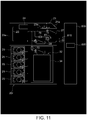
- the banknotes after the curl of the banknote has been corrected by the curl correction mechanism 70 can be stacked in the escrow unit for bundling 80 in which the banknotes that should be bundled by using the bundling medium are temporarily stacked.
- the banknote handling apparatus 20r according to the example shown in FIG. 11 can be used along with a bundling device 800 that bundles the banknotes temporarily stacked in the escrow unit for bundling 80.
- the bundling device 800 includes a transport arm 810 for transporting to the bundling device 800 a bundle of banknotes of a predetermined number (for example, 100 banknotes) stacked in the escrow unit for bundling 80, and a bundling part 820.
- the upper unit 102 includes a banknote inserting unit 110 for inserting a banknote to the inside of the housing 101a from the outside thereof, a transport unit 112 that transports the banknote inserted by the banknote inserting unit 110 to the inside of the housing 101a, a recognition unit 114 arranged in the transport unit 112 and that recognizes the banknote transported by the transport unit 112, and a banknote ejecting unit 116 for ejecting the banknote to the outside of the housing 101a from the inside thereof.
- the recognition unit 114 recognizes a denomination, an authenticity, a fitness, a version, a face side up / back side up, a transportation state and the like of the banknote transported by the transport unit 112.
- the banknote recognized by the recognition unit 114 is sent, for example, to one of later-explained storing and feeding units 120 by the transport unit 112 according to the denomination of the banknote.
- the banknote is sent to the cassette mounting unit 140 after the curl habit of the banknote having the curl habit fed from each of the storing and feeding units 120 is corrected. Therefore, it is possible to suppress the occurrence of a stacking failure of the banknotes stacked in the banknote collecting cassette 142 mounted in the cassette mounting unit 140.
- the banknote that is stored by the winding members being wound on a certain drum (for example, the drum 122a of the first storing and feeding unit 120 from the top) is sent to the cassette mounting unit 140, and the banknote is stacked in the banknote collecting cassette 142.
- This banknote fed from the first storing and feeding unit 120 from the top has the curl habit; however, because all the banknotes fed from the first storing and feeding unit 120 from the top will have the curl habit in the same direction, a stacking failure is less likely to occur in the banknote collecting cassette 142.
- one banknote storing mechanism among the banknote storing mechanism 122, 124, 126 can be used for reconciliation of the banknote, and the banknote is not stored in this banknote storing mechanism other than when performing the reconciliation process of the banknote.
- the banknote can be sent to the cassette mounting unit 140 after the curl habit of all banknotes stored in each of the storing and feeding units 120 is corrected by using the banknote storing mechanism for reconciliation.
- the curl correction mechanism 170 is omitted, and the banknote fed from each of the storing and feeding units 120 is to be directly sent to the cassette mounting unit 140. Even in this case, the occurrence of a stacking failure in the banknote collecting cassette 142 mounted in the cassette mounting unit 140 can be suppressed by using the following method. More particularly, first, among the banknote stored in each of the storing and feeding units 120, all the banknotes (for example, the banknote stored in each of the banknote storing mechanism 122 and 126) that have the curl habit in a certain direction are sent to the cassette mounting unit 140.
Landscapes
- Engineering & Computer Science (AREA)
- Mechanical Engineering (AREA)
- Physics & Mathematics (AREA)
- General Physics & Mathematics (AREA)
- Pile Receivers (AREA)
- Separation, Sorting, Adjustment, Or Bending Of Sheets To Be Conveyed (AREA)
Abstract
Description
- The present invention relates to a sheet handling apparatus that handles a sheet such as a banknote, and a sheet handling method implemented by the sheet handling apparatus.
- Various types of sheet handling apparatuses that handle a sheet, for example a paper sheet such as a banknote, are currently in use. Specifically, a paper sheet handling apparatus disclosed in Japanese Patent Application Laid-Open No.
2012-174134 JP2012-174134A JP2012-174134A JP2012-174134A - In the conventional paper sheet handling apparatus disclosed in
JP2012-174134A - The present invention has been made in view of the above discussion. One object of the present invention is to provide a sheet handling apparatus and a sheet handling method capable of preventing problems occurring due to the curl of the sheet fed by the storing and feeding unit.
- A sheet handling apparatus of the present invention is a sheet handling apparatus including: a storing and feeding unit in which a sheet is stored on a rotary member by winding the sheet on the rotary member and the sheet wound on the rotary member can be fed from the rotary member; a transport unit that transports the sheet fed from the storing and feeding unit; a curl correction mechanism arranged in the transport unit to correct a curl of the sheet transported by the transport unit; and a stacking unit connected to the transport unit and in which the sheet that has passed through the curl correction mechanism is stacked.
- The sheet handling apparatus of the present invention may further include a control unit that adjusts a degree of correction of the curl of the sheet by the curl correction mechanism based on at least one of processing contents of the sheet by the sheet handling apparatus; a storing state of the sheet in the storing and feeding unit; and a feature of the sheet fed from the storing and feeding unit.
- In the sheet handling apparatus of the present invention, the control unit may adjust the degree of correction of the curl of the sheet by the curl correction mechanism by changing a transport speed of the sheet in the transport unit.
- Alternatively, the control unit may adjust the degree of correction of the curl of the sheet by the curl correction mechanism by changing a state of the curl correction mechanism.
- In this case, the curl correction mechanism may include a curl correction member capable of contacting with and separating from the sheet transported by the transport unit, and the control unit may change the state of the curl correction mechanism by changing a position of the curl correction member.
- Further, the curl correction member may be movable between an operating position at which the curl correction member is nearest to the sheet transported by the transport unit, and a retracted position at which the correction of the curl of the sheet transported by the transport unit is not performed, and the control unit may perform a control to perform the correction of the curl of the sheet and not to perform the correction of the curl of the sheet by moving the curl correction member to one of the operating position and the retracted position.
- In the sheet handling apparatus of the present invention, the storing state of the sheet in the storing and feeding unit may include a state based on a distance from a rotation axis of the rotary member to the stored sheet.
- In this case, the control unit may increase the degree of correction of the curl of the sheet by the curl correction mechanism when a distance from the rotation axis of the rotary member to the sheet stored in the storing and feeding unit is smaller than a predetermined threshold.
- In the sheet handling apparatus of the present invention, the storing state of the sheet in the storing and feeding unit may include a state based on a time duration for which the sheet is stored in the storing and feeding unit.
- In the sheet handling apparatus of the present invention, the feature of the sheet may include at least one factor among a denomination, a short edge length, a long edge length, a thickness, and material of the sheet.
- In the sheet handling apparatus of the present invention, the stacking unit may be one of: a collecting unit in which can be stacked the sheet that should be collected; an ejecting unit that ejects the sheet outside of a housing from inside thereof; and an escrow unit for bundling in which the sheet that should be bundled by using a bundling medium is temporarily stacked.
- In this case, when a collection process of the sheet is performed, the sheet fed to the transport unit from the storing and feeding unit may be sent to the collecting unit after passing the curl correction mechanism.
- Further, the collecting unit may be one of a collection bag and a collecting cassette that can be detachably attached to a device body.
- The sheet handling apparatus of the present invention may further include an inserting unit for inserting the sheet inside a housing from outside thereof, and the inserting unit may be connected to the transport unit, the sheet inserted from the inserting unit inside the housing from outside thereof may be sent to one of the storing and feeding unit and the stacking unit by the transport unit, and the curl correction mechanism may be arranged in the transport unit at a position between the storing and feeding unit and the stacking unit.
- In this case, the sheet handling apparatus of the present invention may further include a control unit that adjusts a degree of correction of the curl of the sheet by the curl correction mechanism based on at least one of processing contents of the sheet by the sheet handling apparatus; a storing state of the sheet in the storing and feeding unit; and a feature of the sheet fed from the storing and feeding unit, and the control unit may adjust the degree of correction of the curl of the sheet by the curl correction mechanism, as the processing contents of the sheet by the sheet handling apparatus, so that the degree of correction of the curl of the sheet is set higher when transporting by the transport unit the sheet fed to the transport unit from the storing and feeding unit than the degree of correction of the curl of the sheet when transporting by the transport unit the sheet inserted from the inserting unit inside the housing.
- A sheet handling method of the present invention is a sheet handling method including: feeding a sheet wound on a rotary member of a storing and feeding unit from the rotary member; transporting the sheet fed to a transport unit from the storing and feeding unit; correcting a curl of the sheet transported by the transport unit by using a curl correction mechanism; and stacking the sheet that has passed through the curl correction mechanism in a stacking unit.
- In the sheet handling method of the present invention, a degree of correction of the curl of the sheet by the curl correction mechanism may be adjusted based on at least one of processing contents of the sheet; a storing state of the sheet in the storing and feeding unit, and a feature of the sheet fed from the storing and feeding unit.
-
-
FIG. 1 is a perspective view of an external appearance of a money handling machine according to one embodiment of the present invention. -
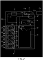
FIG. 2 is a side view of an internal configuration of a banknote handling apparatus in the money handling machine shown inFIG. 1 . -
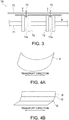
FIG. 3 is a structural diagram of a configuration of a curl correction mechanism arranged in the banknote handling apparatus shown inFIG. 2 . -
FIG. 4A is a view for explaining a state before curl of a banknote having a curl habit is corrected by the curl correction mechanism shown inFIG. 3 . -
FIG. 4B is a view for explaining a state after the curl of the banknote having the curl habit is corrected by the curl correction mechanism shown inFIG. 3 . -
FIG. 5 is a side view of a detailed configuration of a banknote storing mechanism in the banknote handling apparatus shown inFIG. 2 . -
FIG. 6 is a perspective view of a configuration including a pair of holding members and the like in the banknote storing mechanism shown inFIG. 5 . -
FIG. 7 is a perspective view of a configuration of a banknote collection bag that is to be held by the holding members of the banknote storing mechanism shown inFIG. 5 and the like. -
FIG. 8 is a functional block diagram indicating a configuration of a control system in the banknote handling apparatus shown inFIG. 2 and the like. -
FIG. 9 is a side view of another example of an internal configuration of the banknote handling apparatus according to the present embodiment. -
FIG. 10 is a side view of still another example of an internal configuration of the banknote handling apparatus according to the present embodiment. -
FIG. 11 is a side view of still another example of an internal configuration of the banknote handling apparatus according to the present embodiment. -
FIG. 12 is a side view of still another example of an internal configuration of the banknote handling apparatus according to the present embodiment. -
FIG. 13 is a side view of still another example of an internal configuration of the banknote handling apparatus according to the present embodiment. -
FIG. 14 is a structural diagram of a configuration of a banknote storing cassette of the banknote handling apparatus of the example shown inFIG. 13 . -
FIG. 15 is a view for explaining a state when the curl of the banknote is corrected by a shape of a transport unit. - Exemplary embodiments in which a banknote handling apparatus that handles a banknote is used as a sheet handling apparatus according to the present invention are explained below in detail. Moreover, in the present embodiment, a money handling machine that includes the banknote handling apparatus and a coin handling apparatus is also explained.
-
FIGS. 1 to 15 are views of the banknote handling apparatus according to the present embodiment and the money handling machine including this banknote handling apparatus. Among them,FIG. 1 is a perspective view of an external appearance of the money handling machine according to one embodiment of the present invention, andFIG. 2 is a structural diagram of an internal configuration of the banknote handling apparatus in the money handling machine shown inFIG. 1 .FIG. 3 is a structural diagram of a configuration of a curl correction mechanism arranged in the banknote handling apparatus shown inFIG. 2 .FIGS. 4A and 4B are respectively views for explaining a state before and after the curl of the banknote having a curl habit is corrected by the curl correction mechanism shown inFIG. 3 .FIGS. 5 to 8 are structural diagrams of a configuration of a banknote storing mechanism in the banknote handling apparatus shown inFIG. 2 .FIGS. 9 to 13 are side views of various other examples of an internal configuration of the banknote handling apparatus according to the present embodiment.FIG. 14 is a structural diagram of a configuration of a banknote storing cassette of the banknote handling apparatus of the example shown inFIG. 13 .FIG. 15 is a view for explaining a state when the curl of the banknote is corrected by a shape of a transport unit. InFIGS. 3, 4A, 4B , and14 , the banknote handled by the banknote handling apparatus according to the present embodiment is shown with a reference letter P. Moreover, inFIG. 4B , a habit such as folds and the like made in the banknote by the curl correction mechanism is shown with a reference letter Q. - At first, a configuration of a
money handling machine 1 according to one embodiment of the present invention is explained by referring toFIG. 1 . Generally, a shop such as a supermarket is divided into a front area in which a salesclerk deposits and / or dispenses money actually exchanged with the customer, and a backyard area in which the money and the products used in the front area are managed. One or more money settlement machines (e.g., money change machine) are installed in the front area. Themoney handling machine 1 shown inFIG. 1 is installed in the backyard area. The money settlement machine is operated by a salesclerk. Cash settlement process between the salesclerk and a customer is carried out by using the money settlement machine. For example, the money settlement machine is used to deposit the money received from the customer and to dispense a change to be returned to the customer. Moreover, themoney handling machine 1 is used to dispense a change fund for loading into the money settlement machine and to deposit proceeds of sales collected from the money settlement machine. By using a money storing cassette (specifically, a later-explainedbanknote storing cassette 21c) that can be detachably attached to each of the money settlement machine and themoney handling machine 1, the money can be exchanged between the money settlement machine and themoney handling machine 1. Note that, the money stored in the money storing cassette cannot be taken out when the money storing cassette is in the detached state from the money settlement machine and themoney handling machine 1. - As shown in
FIG. 1 , themoney handling machine 1 installed in the backyard area includes abanknote handling apparatus 20 and acoin handling apparatus 90. Thebanknote handling apparatus 20 is used to dispense banknotes to be loaded in the money settlement machine installed in the front area, and to deposit banknotes collected from the money settlement machine. Thecoin handling apparatus 90 is used to dispense coins to be loaded in the money settlement machine installed in the front area, and to deposit coins collected from the money settlement machine. - Subsequently, the configuration of the
banknote handling apparatus 20 is explained by usingFIGS. 1 and2 . Aside surface on the right side of a later-explainedhousing 20a inFIG. 2 is a front surface side of a banknote handling apparatus 20 (that is, a front side of thebanknote handling apparatus 20 when the apparatus is seen from the front side shown inFIG. 1 ), and the left direction inFIG. 2 is a depth direction of thehousing 20a. - As shown in
FIG. 1 , thebanknote handling apparatus 20 includes thehousing 20a, an insertingunit 21, an ejectingunit 22, and an operation/display unit 29. Abanknote receiving unit 21a is detachably attached to the insertingunit 21. Thebanknote receiving unit 21a receives banknotes from the outside of thebanknote handling apparatus 20 and by using abanknote feeding mechanism 21b feeds the banknotes one by one inside thehousing 20a. Thebanknote receiving unit 21a is used when an operator (that is, the salesclerk) manually deposits the banknotes in thebanknote handling apparatus 20. The above-mentioned money storing cassette (specifically, thebanknote storing cassette 21c (seeFIG. 2 )) can be mounted in the insertingunit 21 instead of thebanknote receiving unit 21a. When thebanknote storing cassette 21c is mounted in the insertingunit 21, the banknotes in thebanknote storing cassette 21c are fed one by one inside thehousing 20a by a feeding mechanism arranged in thebanknote storing cassette 21c. The ejectingunit 22 stacks in a stacked manner the banknote fed from a later-explained storing and feedingunit 25. The banknotes stacked in the ejectingunit 22 can be accessed from the outside of thehousing 20a. In thebanknote handling apparatus 20 according to the present embodiment, the ejectingunit 22 functions as a stacking unit according to present invention. - The operation/
display unit 29 displays various information such as storing states of the banknote and the coin in themoney handling machine 1. Moreover, the operator can input data by using the operation/display unit 29. The operation/display unit 29 is constituted by, for example, a touch screen-type display, and the like. Note that, the operation/display unit 29 is arranged in one of thebanknote handling apparatus 20 and thecoin handling apparatus 90; however, the operation/display unit 29 is shared by both of them to display the information. - As shown in
FIG. 2 , inside thehousing 20a of thebanknote handling apparatus 20 is arranged atransport unit 23 for transporting the banknotes one by one. The above-mentioned insertingunit 21 is connected to oneend 23a of thetransport unit 23. When thebanknote receiving unit 21a is mounted in the insertingunit 21, the banknote fed from thebanknote receiving unit 21a is transported by thetransport unit 23 through theend 23a of thetransport unit 23. - As shown in
FIG. 2 , arecognition unit 24 is arranged in thetransport unit 23. Therecognition unit 24 performs recognition such as a denomination, a fitness, an authenticity of the banknote transported by thetransport unit 23. Specifically, therecognition unit 24 includes an image sensor, a magnetic sensor, a thickness sensor, and the like. More particularly, for example, the image sensor captures an image of the banknote transported by thetransport unit 23, and recognition of information about the banknote is performed based on the captured image of the banknote. Moreover, based on the captured image, a detection result obtained by the magnetic sensor, and the like, a short edge length (that is, a length of a short side of the banknote) of the banknote transported by thetransport unit 23, a long edge length (that is, a length of a long side of the banknote), material (paper, polymer, and the like), and a printing state (for example, excess or deficiency of ink used for printing the banknote), and the like, can be detected. Moreover, for example, when the banknote transported by thetransport unit 23 is a banknote including a plurality of material, such as a hybrid banknote (for example, a banknote in which polymer film is stuck on a part of a paper banknote, a banknote formed by sandwiching liner-shaped polymer film running parallel to the short side direction of the banknote between a pair of paper strips), therecognition unit 24 detects a position, a width, and the like of the polymer film in addition to the denomination, the fitness, the authenticity, the dimensions, the materials, and the like. Therecognition unit 24 also detects a thickness of the banknote passing therecognition unit 24. Moreover, when the banknote is a banknote in which a metal wire and the like is embedded to prevent a fraudulent activity (for example, forgery of banknote, and the like), therecognition unit 24 also detects a position, number, a width, and the like of the embedded metal wire in addition to the denomination, the fitness, the authenticity, the dimensions, the materials, and the like. The information about the banknote recognized by therecognition unit 24 is sent to a later-explainedcontrol unit 50. Accordingly, therecognition unit 24 recognizes (detects) the features of the banknote. - In an alternative configuration, the information that the denomination is associated with the material, the position and the width of the polymer film, and the like of the banknote can be previously stored in a later-explained
memory 52. This allows thecontrol unit 50 to determine the material, the position and the width of the polymer film, and the like of the banknote based on the denomination of the banknote recognized by therecognition unit 24. - As shown in
FIG. 2 , thebanknote handling apparatus 20 is provided with anoutside reject unit 27 and aninside reject unit 28. Among the banknotes inserted in thehousing 20a from the insertingunit 21, a banknote that is recognized by therecognition unit 24 as not being a normal banknote is sent as a reject banknote to theoutside reject unit 27 by thetransport unit 23. Such a reject banknote is ejected outside thebanknote handling apparatus 20 by using theoutside reject unit 27. On the other hand, a reject banknote that cannot be ejected outside thebanknote handling apparatus 20 is sent to theinside reject unit 28 by thetransport unit 23. Such a reject banknote is stored in theinside reject unit 28. An operator such as the salesclerk who does not have management powers and authorities cannot take out the banknote present in theinside reject unit 28. - A plurality of the storing and feeding
units 25 is arranged in thehousing 20a. Each of the storing and feedingunits 25 is connected to thetransport unit 23. Each of the storing and feedingunits 25 stores therein a banknote according to a denomination of the banknote. More particularly, based on the recognition result obtained in therecognition unit 24, the banknote fed to thetransport unit 23 from the insertingunit 21 is sent by thetransport unit 23 to one of the storing and feedingunits 25 according to the denomination of the banknote. It is allowable to store a banknote of a foreign currency and the like that is not assigned to any of the storing and feedingunits 25 in one of the storing and feedingunits 25. Moreover, it is allowable to store an overflow banknote, which is a banknote that cannot be stored in the storing and feedingunit 25 because this storing and feedingunit 25 to which is assigned banknotes of a certain denomination is full, in another storing and feedingunit 25. In the storing and feedingunit 25 in which the foreign currency banknotes and the overflow banknotes are stored, the banknotes will be stored in a state in which the denominations and the like are mixed. - Each of the storing and feeding
units 25 can feed the banknotes stored in the storing and feedingunit 25 one by one to thetransport unit 23. Specifically, each of the storing and feedingunit 25 includes a substantiallycylindrical drum 25a (that is, a rotary member) adapted to rotate around arotation axis 25c. One end of a belt-shaped windingmember 25b that winds on the drum a plurality of banknotes one by one is connected to an outer peripheral surface of thedrum 25a. The banknotes are stored when the windingmember 25b is wound on thedrum 25a along with the banknotes, and the stored banknotes are fed from thedrum 25a when the windingmember 25b is unwound from thedrum 25a. That is, the banknotes are stored in a curled state in each of the storing and feedingunits 25. Therefore, the banknote fed from each of the storing and feedingunits 25 to thetransport unit 23 has a curl habit. More particularly, when thetransport unit 23 is adapted to transport the banknotes in a direction that is parallel to the long side of the banknotes, the banknotes are stored in the storing and feedingunit 25 such that the long side of the banknote substantially coincides with a circumferential direction of thedrum 25a. Therefore, the banknote fed from the storing and feedingunit 25 to thetransport unit 23 has a curl habit along the long side of the banknote (seeFIG. 4A ). A banknote having the curl habit is, for example, as shown inFIG. 4A , a banknote that remains in a bent (curled) state unless some external force is applied thereto. Moreover, the curl habit of the banknote can be corrected only by applying the external force to the banknote. Moreover, a strong curl habit of the banknote means that, it is necessary to apply a stronger external force to the banknote, or to apply the external force for a longer time to the banknote to correct the curl habit of the banknote. As explained below, a winding strength by which the windingmember 25b is wound around thedrum 25a in each of the storing and feedingunit 25 can be adjusted by thecontrol unit 50. - In the
banknote handling apparatus 20 according to the present embodiment, a banknote storing mechanism 32 (seeFIG. 2 ) is arranged inside thehousing 20a. A later-explainedbanknote collection bag 34 for storing therein the banknotes in a stacked state is detachably attached to thebanknote storing mechanism 32. The banknotes sent to thebanknote storing mechanism 32 from the storing and feedingunit 25 via thetransport unit 23 are stored in the stacked manner in thebanknote collection bag 34. Thebanknote collection bag 34 functions as a collecting unit (stacking unit) according to present invention. - The banknote of a denomination that is not assigned to any of the storing and feeding
unit 25, and an overflow banknote that cannot be stored in the storing and feedingunit 25 corresponding to the denomination of this banknote because the storing and feedingunit 25 is full are also stored in thebanknote collection bag 34. By taking thebanknote collection bag 34 out of thebanknote storing mechanism 32, the banknotes stored in thebanknote collection bag 34 can be collected from thebanknote handling apparatus 20. A configuration of thebanknote storing mechanism 32 will be explained in detail later. - In the
banknote handling apparatus 20 according to the present embodiment, acurl correction mechanism 70 that corrects the curl of the banknote transported by thetransport unit 23 is arranged in thetransport unit 23 near thebanknote storing mechanism 32. As shown inFIG. 3 , thecurl correction mechanism 70 includes a pair oflower rollers 72 arranged rotatably on a position-fixedaxis 71, and a pair of upper rollers 74 (that is, curl correction member) arranged rotatably on anaxis 73 that is movable in an up-down direction inFIG. 3 with respect to theaxis 71. Thelower rollers 72 and theupper rollers 74 are driven by a not-shown driving motor. Each of thelower rollers 72 has agroove 72a near a center in a width direction of thelower roller 72. Theupper rollers 74 and thelower rollers 72 are arranged such that theupper roller 74 opposes thegroove 72a of the correspondinglower roller 72 across a transport path of the banknote. Moreover, a width of thegroove 72a in an axial direction of the axis 71 (that is, left-right direction inFIG. 3 ) is larger than a width of theupper roller 74. Therefore, in thecurl correction mechanism 70, a partial area of the banknote (marked with the reference letter P inFIG. 3 ) passing through thecurl correction mechanism 70 can be pushed with theupper rollers 74 inside thegrooves 72a of thelower rollers 72. Accordingly, thecurl correction mechanism 70 can apply a habit such as folds that is different from the curl habit (seeFIG. 4B ) to the banknote fed to thetransport unit 23 from the storing and feedingunit 25 thereby correcting the curl of the banknote. - More particularly, the banknote fed to the
transport unit 23 from the storing and feedingunit 25 has the curl habit (that is, the curl habit along a transport direction (long side) of the banknote) as shown inFIG. 4A , and the banknote is transported in the left-right direction (that is, a direction that is parallel to the transport direction (long side) of the banknote) inFIG. 4A . Thecurl correction mechanism 70 corrects the curl of the banknote by applying a habit, such as folds, to the banknote along the transport direction (long side) of the banknote. Specifically, the curl of the banknote having the curl habit as shown inFIG. 4A is corrected by applying with thecurl correction mechanism 70 the habit (marked with the reference letter Q inFIG. 4B ), such as folds, as shown inFIG. 4B . More specifically, the banknote transported by thetransport unit 23 is transported in a state in which the banknote is pinched by various components of thetransport unit 23. Therefore, regardless of whether the banknote transported by thetransport unit 23 has the curl habit, a shape of the banknote transported by thetransport unit 23 is flat when seen from a side (that is, when seen from a direction that is orthogonal to the paper surface ofFIG. 2 ). When the banknote is pinched such that the banknote is flat when seen from the side and is transported in the flat state by thetransport unit 23, by applying the habit of folds and the like along the transport direction (long side) of the banknote, stiffness against bending in the transport direction of the banknote can be increased. Accordingly, thecurl correction mechanism 70 can correct the curl habit of the banknote. - The
curl correction mechanism 70 includes a movement mechanism 75 (seeFIG. 8 ) that integrally moves theupper rollers 74 in a direction of an arrow shown inFIG. 3 (that is, up-down direction inFIG. 3 ). More particularly, themovement mechanism 75 can move theupper rollers 74 in the up-down direction inFIG. 3 at a desirable position between an operating position at which theupper rollers 74 are nearest to the banknote making it possible to correct the curl of the banknote and a retracted position at which the correction of the curl of the banknote is not performed. Accordingly, it is possible to control whether to correct the curl of the banknote passing through thecurl correction mechanism 70. - It is allowable to adopt a configuration in which a position in the up-down direction in
FIG. 3 of each of theupper rollers 74 can be adjusted by using themovement mechanism 75. In this configuration, thecurl correction mechanism 70 can adjust a strength of the habit (marked with the reference letter Q inFIG. 4B ) such as folds to apply to the banknote. - In the
banknote handling apparatus 20 according to the present embodiment, a degree of correction of the curl of the banknote by thecurl correction mechanism 70 can be adjusted by adjusting a transport speed of the banknote transported by thetransport unit 23. More particularly, when the transport speed of the banknote by thetransport unit 23 is slow, the banknote transported on thetransport unit 23 takes a longer time to pass through thecurl correction mechanism 70. In other words, by setting the transport speed of the banknote by thetransport unit 23 slow, the correction of the curl of the banknote by thecurl correction mechanism 70 can be performed for a longer time. Thus, by setting the transport speed of the banknote by thetransport unit 23 slow, the degree of correction of the curl of the banknote by thecurl correction mechanism 70 can be increased. - Subsequently, a detailed configuration of the
banknote storing mechanism 32 in thebanknote handling apparatus 20 is explained by usingFIGS. 5 to 7 .FIG. 5 is a side view of a detailed configuration of thebanknote storing mechanism 32.FIG. 6 is a perspective view of a configuration including a pair of holdingmembers 36 and the like in thebanknote storing mechanism 32 shown inFIG. 5 .FIG. 7 is a perspective view of a configuration of thebanknote collection bag 34 that is to be held by the holdingmembers 36 of thebanknote storing mechanism 32 shown inFIG. 5 and the like. - As shown in
FIG. 5 , abanknote feeding unit 48 is constituted by a combination of rollers and belts. Thebanknote feeding unit 48 causes the banknote sent to thebanknote storing mechanism 32 by thetransport unit 23 to be sent one by one toescrow units 44 and stacked on theescrow units 44. Oneescrow unit 44 is arranged on the right side and anotherescrow unit 44 is arranged on the left side. A base end of each of theescrow units 44 is rotatably supported by anaxis 44a such that theescrow unit 44 can rotate in a lower direction (that is, in a direction of a curved arrow inFIG. 5 ) around theaxis 44a. Onestage 40 is arranged on the right side and anotherstage 40 is arranged on the left side. Each of thestages 40 is movable in the up-down direction and left-right direction inFIG. 5 . A gap is secured between the pair ofstages 40. A portion of thebanknote collection bag 34 held by the holdingmembers 36 passes through the gap between thestages 40 and protrudes downward. Each of thestages 40 is driven by a stage driving unit 41 (seeFIG. 8 ) such as an electric actuator. Each of thestages 40 includes aheating member 42. Before thebanknote collection bag 34 is taken out of thebanknote storing mechanism 32, in a state in which one stage 40 (for example, thestage 40 on the left side inFIG. 5 ) is moved towards the other stage 40 (for example, thestage 40 on the right side inFIG. 5 ) and both thestages 40 are in contact with each other, heat sealing of a bottom part of thebanknote collection bag 34 is performed by applying heat to a part near the bottom part of thebanknote collection bag 34 with theheating members 42. - As shown in
FIG. 6 , theleft holding member 36 among the pair of left and right holdingmembers 36 is provided with apantograph 37. Theleft holding member 36 can be moved towards theright holding member 36 by thepantograph 37 so that the two holdingmembers 36 contact each other. More particularly, guide pins 36p are arranged at ends of theleft holding member 36. Elongated through-holes 36q are formed inframes 36k that support the holdingmembers 36, and the guide pins 36p are guided in the elongated through-holes 36q. The elongated through-holes 36q extend horizontally in theframes 36k. When thepantograph 37 extends, because the guide pins 36p arranged in theleft holding member 36 are guided along the elongated through-holes 36q, theleft holding member 36 moves toward theright holding member 36. - As shown in
FIG. 6 , twopins 36a are arranged on a top surface of each of the left and right holdingmembers 36. As shown inFIG. 7 , thebanknote collection bag 34 to be held by the holdingmembers 36 has a pair of protrudingparts 34a near the opening thereof (that is, near an upper edge of the banknote collection bag 34), and each of the protrudingparts 34a is provided with a pair ofholes 34b. When thebanknote collection bag 34 is to be held by the holdingmembers 36, thepins 36a of the holdingmembers 36 are inserted in the correspondingholes 34b formed in the corresponding protrudingparts 34a of thebanknote collection bag 34. As a result, the protrudingparts 34a are held by the holdingmembers 36. - Moreover, as shown in
FIG. 5 , a pushingplate 46 is arranged above the pair ofescrow units 44. Apantograph 47 is arranged above the pushingplate 46. When thepantograph 47 expands downward, the pushingplate 46 is moved downward from its position shown inFIG. 5 . Because of the downward movement of the pushingplate 46 from its position shown inFIG. 5 , when the banknotes escrowed on theescrow units 44 are stored into thebanknote collection bag 34, any banknote that may have remained on theescrow units 44 can be pushed toward thebanknote collection bag 34. - As shown in
FIG. 5 , a pushinglever 39 is arranged below theleft holding member 36 of the pair of holdingmembers 36. Because of the pushinglever 39, the banknotes stored in thebanknote collection bag 34 held by the pair of holdingmembers 36 are pushed toward one side (specifically, to the right side inFIG. 5 ) in thebanknote collection bag 34. More particularly, the pushinglever 39 is moved to the right side from its state shown inFIG. 5 by a pushinglever driving unit 39a (seeFIG. 8 ). The pushinglever driving unit 39a is constituted by a pantograph, an electric actuator, and the like. - In the
banknote storing mechanism 32, animage capturing unit 60, such as a camera, for capturing an image of an inner wall part of thebanknote collection bag 34 is arranged near the opening of thebanknote collection bag 34 held by the holdingmembers 36. Moreover, amark 34c (seeFIG. 5 ) is arranged on the inner wall part near the opening of thebanknote collection bag 34 held by the holdingmembers 36. An image of thismark 34c is captured by theimage capturing unit 60. Moreover, alight source 62 that emits a light on the inner wall part of thebanknote collection bag 34 held by the holdingmembers 36 is arranged near theimage capturing unit 60. By emitting the light on the inner wall part of thebanknote collection bag 34 from thelight source 62, a clear image of themark 34c, which is arranged on the inner wall part near the opening of thebanknote collection bag 34, can be captured by theimage capturing unit 60. - In the
banknote storing mechanism 32, an operation when the banknote sent to thebanknote storing mechanism 32 by thetransport unit 23 is stored in thebanknote collection bag 34 held by the pair of holdingmembers 36 is explained in detail below. - The banknote sent to the
banknote storing mechanism 32 by thetransport unit 23 is sent by thebanknote feeding unit 48 on the pair of left andright escrow units 44 and is stacked on thoseescrow units 44. When a predetermined number of the banknotes are stacked on theescrow units 44, each of theescrow units 44 rotates below (that is, in the direction of the curved arrow shown inFIG. 5 ) around theaxis 44a provided at the base end thereof. The banknotes stacked on theescrow units 44 fall from theescrow units 44 by own weight, and are stored in thebanknote collection bag 34. When the banknotes fall from theescrow units 44 and are stored in thebanknote collection bag 34, thestages 40 are moved downward by thestage driving unit 41 whereby a storage space for the subsequent banknotes that may be sent from theescrow units 44 to thebanknote collection bag 34 is formed in thebanknote collection bag 34. In the present embodiment, when sending the banknotes in thebanknote collection bag 34 held by the holdingmembers 36 to store the banknotes in thebanknote collection bag 34, thecontrol unit 50 controls thepantograph 47 to push with the pushingplate 46 the banknote escrowed on theescrow units 44 into thebanknote collection bag 34. Accordingly, even if a banknote remains on theescrow units 44, this banknote can be caused to fall from theescrow units 44 and stored in thebanknote collection bag 34. - When the banknote is stored in the
banknote collection bag 34 held by the holdingmembers 36, an image of themark 34c arranged on the inner wall part of thebanknote collection bag 34 is always captured by theimage capturing unit 60. When the banknotes of the predetermined quantity are stored in thebanknote collection bag 34, themark 34c is blocked by the banknotes stored in thebanknote collection bag 34 and does not appear in the image captured by theimage capturing unit 60. When this happens, thecontrol unit 50 determines that thebanknote collection bag 34 is full or nearly full. Thus, because a top surface of the banknotes stored in thebanknote collection bag 34 can be detected based on the image captured by theimage capturing unit 60, as explained below, when theleft holding member 36 moves towards theright holding member 36 and an opening of thebanknote collection bag 34 is heat sealed byheating members 38, it is possible to prevent that the banknotes stored in thebanknote collection bag 34 are pinched by the holdingmembers 36, and a not-sealed portion occurs in the opening of thebanknote collection bag 34. Note that, it is allowable to adopt a configuration in which thecontrol unit 50 determines that thebanknote collection bag 34 is full or nearly full based on the pushing operation of theescrow units 44 by the pushingplate 46. More particularly, when thebanknote collection bag 34 is full or nearly full, the banknotes stored in thebanknote collection bag 34 will exist inside a movement area (see the curved arrows inFIG. 5 ) of theescrow units 44. In this case, because free ends of theescrow units 44 will touch the banknotes stored in thebanknote collection bag 34 when theescrow units 44 are pushed by the pushingplate 46 into thebanknote collection bag 34, theescrow units 44 can no longer be pushed in thebanknote collection bag 34. Based on this fact, it can be determined whether thebanknote collection bag 34 is full or nearly full. Note that, it is allowable to adopt a configuration in which theescrow units 44 are arranged at a position that is above their position shown inFIG. 5 such that the banknotes stored in thebanknote collection bag 34 do not exist in the movement area of theescrow units 44, and thecontrol unit 50 determines whether thebanknote collection bag 34 is full or nearly full based on the pushing operation of the pushingplate 46. More particularly, when thebanknote collection bag 34 is full or nearly full, when pushing the banknotes escrowed on theescrow units 44 with the pushingplate 46 in thebanknote collection bag 34, the distance for which the pushingplate 46 can be moved toward thebanknote collection bag 34 will be shorter as compared to this distance when thebanknote collection bag 34 is not full or nearly full. Based on this fact, it can be determined whether thebanknote collection bag 34 is full or nearly full. - When it is determined that the
banknote collection bag 34 is full or nearly full, thebanknote collection bag 34 is taken out of thebanknote storing mechanism 32. However, before thebanknote collection bag 34 is taken out of thebanknote storing mechanism 32, the pushinglever 39 is moved by the pushinglever driving unit 39a toward the right direction inFIG. 5 , and the banknotes stored in thebanknote collection bag 34 are pushed by the pushinglever 39 toward one side in thebanknote collection bag 34. Then, when the pushinglever 39 returns to its original position, a gap is formed between the left inner wall part of thebanknote collection bag 34 and the banknotes that have been pushed to the one side in thebanknote collection bag 34. After the banknotes stored in thebanknote collection bag 34 held by the holdingmembers 36 are pushed by the pushinglever 39 toward the one side (specifically, the right side inFIG. 5 ) in thebanknote collection bag 34, theleft stage 40 moves toward theright stage 40 inFIG. 5 and contacts theright stage 40, and the heat sealing of the bottom part of thebanknote collection bag 34 is performed by applying heat to the part near the bottom part of thebanknote collection bag 34 with theheating members 42. Then, theleft holding member 36 moves toward theright holding member 36 inFIG. 5 and contacts theright holding member 36, and the heat seal sealing of the opening of thebanknote collection bag 34 is performed by applying heat to the part near the opening of thebanknote collection bag 34 with theheating members 38. Accordingly, the operator can withdraw the opening and the bottom part sealedbanknote collection bag 34 from thebanknote storing mechanism 32. - The
banknote handling apparatus 20 according to the present embodiment includes thecontrol unit 50 that controls various structural components of thebanknote handling apparatus 20. More particularly, as shown inFIG. 8 , to thecontrol unit 50 are connected thebanknote feeding mechanism 21b provided in thebanknote receiving unit 21a mounted in the insertingunit 21, a stackingwheel driving unit 22b that drives a stackingwheel 22a provided in the ejectingunit 22, thetransport unit 23, therecognition unit 24, the storing and feedingunit 25, the operation/display unit 29, the banknote storing mechanism 32 (specifically, thepantograph 37, theheating members 38, the pushinglever driving unit 39a, thestage driving unit 41, theheating members 42, theescrow units 44, thepantograph 47, and the banknote feeding unit 48), thememory 52, aprinting unit 54, acommunication interface unit 56, theimage capturing unit 60, thelight source 62, the curl correction mechanism 70 (specifically, the movement mechanism 75), and the like. A signal relating to a recognition result and a detection result of the banknote obtained in therecognition unit 24 and an image captured by theimage capturing unit 60 are sent to thecontrol unit 50, thecontrol unit 50 controls the operation of each of the above-mentioned components of thebanknote handling apparatus 20 by sending a command signal to those components. - Information about the recognition result and the detection result of the banknote obtained in the
recognition unit 24 is stored in thememory 52. A handling history of the money deposition process and the like of the banknotes in thebanknote handling apparatus 20, and the information about the inventory amounts and the like of the banknotes stored in each of thebanknote collection bags 34 are stored in thememory 52. Moreover, identification information (ID) of each of thebanknote collection bags 34 and identification information of the banknotes stored in each of thebanknote collection bags 34 are stored in thememory 52 in an associated manner. Moreover, information about a diameter of thedrum 25a of each of the storing and feedingunits 25 and information about a thickness of the windingmember 25b and information about a set value of the winding strength of the windingmember 25b are stored in thememory 52. Moreover, for all the banknotes stored in each of the storing and feedingunits 25, the order of storing and the date and the time of storing each of the banknotes in each of the storing and feedingunits 25 are stored in thememory 52 in an associated manner. - The
printing unit 54 prints on a receipt and the like the handling history of the money deposition process and the like of the banknotes in thebanknote handling apparatus 20, and the information about the inventory amounts and the like of the banknotes stored in each of thebanknote collection bags 34. Thecontrol unit 50 can transmit to and receive from an external device (specifically, for example, a host terminal) arranged separately from thebanknote handling apparatus 20 according to the present embodiment a signal via thecommunication interface unit 56. Specifically, thecontrol unit 50 can transmit to the external device arranged separately from thebanknote handling apparatus 20 the information stored in thememory 52 via thecommunication interface unit 56. For example, when a guard of a secure transportation company and the like collects the banknotes together with thebanknote collection bag 34, information about the collected banknotes is transmitted to a computer of the secure transportation company and the like via thecommunication interface unit 56. - An operation in each of the money deposition process, the money dispensing process, and a collection process performed in the
banknote handling apparatus 20 according to the present embodiment are explained in detail below. The money deposition process is a process in which, after having recognized by the recognition unit 24 a denomination and the like of the banknotes inserted in thehousing 20a from the insertingunit 21 of thebanknote handling apparatus 20, the banknote is stored, for example, in one of the storing and feedingunits 25 according to the denomination of the banknote. The money dispensing process is a process in which the banknote fed from the storing and feedingunit 25 is ejected in the ejectingunit 22 that is accessible from the outside of thehousing 20a. The collection process is a process in which the banknote inserted in thehousing 20a from the insertingunit 21 or the banknote fed from the storing and feedingunit 25 is sent to thebanknote collection bag 34. - A role in the collection process of the
curl correction mechanism 70 that corrects the curl of the banknote in thebanknote handling apparatus 20 according to the present embodiment is explained below. As explained below, thecurl correction mechanism 70 corrects the curl of the banknote based on the strength of the curl habit of the banknote that passes through thecurl correction mechanism 70. As a pre-stage for this purpose, at first, a factor that determines the strength of the curl habit of the banknote fed to thetransport unit 23 from each of the storing and feedingunits 25 will be explained. The factor that determines the strength of the curl habit of the banknote fed to thetransport unit 23 from each of the storing and feedingunits 25, for example, can arise from a storing state of the banknote, or can arise from material, dimension, and the like of the features of the banknote. - The factors that determine the strength of the curl habit of the banknote fed to the
transport unit 23 from each of the storing and feedingunits 25 and arise from the storing state of the banknote are explained below. As explained above, the banknotes are stored in each of the storing and feedingunits 25 by winding the banknotes one by one with the windingmember 25b on the outer peripheral surface of the substantiallycylindrical drum 25a. Therefore, a distance to the banknote, which has been wound on thedrum 25a by the windingmember 25b, from a center of thedrum 25a (specifically, therotation axis 25c) when seen from a side of thedrum 25a (that is, when seen from the direction that is orthogonal to the paper surface ofFIG. 2 ) is different depending on the order (more particularly, in which winding turn of the windingmember 25b on thedrum 25a the banknote was wound) in which the banknote was wound on thedrum 25a and stored. Specifically, the distance from therotation axis 25c of thedrum 25a to the stored banknote is longer for the banknote that was wound in the 10th winding turn of the windingmember 25b on thedrum 25a and stored than the banknote that was wound in the 1st winding turn of the windingmember 25b on thedrum 25a and stored, for example. In other words, a curvature of the banknote wound by the windingmember 25b on thedrum 25a increases as the distance from therotation axis 25c of thedrum 25a when seen from the side of thedrum 25a to the banknote wound by the windingmember 25b on thedrum 25a reduces. Therefore, the banknote wound by the windingmember 25b on thedrum 25a gets a stronger curl habit. - In this manner, the strength of the curl habit of the banknote wound on the
drum 25a by the windingmember 25b changes based on the distance from therotation axis 25c of thedrum 25a when seen from the side of thedrum 25a to the banknote wound by the windingmember 25b on thedrum 25a. Therefore, if thedrums 25a having different diameters are used in different storing and feedingunits 25, the strength of the curl habit of the banknote fed to thetransport unit 23 from each of the storing and feedingunits 25 will be different depending on the diameter of thedrum 25a of each of the storing and feedingunits 25. That is, if thedrum 25a having a relatively small diameter is used, because the average value of the distance between therotation axis 25c of thedrum 25a and the banknote wound by the windingmember 25b on thedrum 25a is small, the curvature of the banknote wound by the windingmember 25b on thedrum 25a will be relatively large. Therefore, the banknote will be stored in a state in which it will have a strong curl. Therefore, the banknote wound by the windingmember 25b on thedrum 25a having the relatively small diameter will have a strong curl habit on the average. On the other hand, if thedrum 25a having a relatively large diameter is used, because the average value of the distance between therotation axis 25c of thedrum 25a and the banknote wound by the windingmember 25b on thedrum 25a is large, the curvature of the banknote wound by the windingmember 25b on thedrum 25a will be relatively small. Therefore, the banknote will be stored in a state in which it will have a relatively weak curl. Therefore, the banknote wound by the windingmember 25b on thedrum 25a having the relatively large diameter will have a weak curl habit on the average. - Moreover, even if the configuration of each of the storing and feeding units 25 (specifically, the diameter of the
drums 25a and the like), the features of the banknote detected by therecognition unit 24 from the banknote fed to thetransport unit 23 from each of the storing and feeding units 25 (specifically, dimensions, material, printing states, and the like of the banknotes), and the conditions in which the banknote fed to thetransport unit 23 from each of the storing and feedingunits 25 was stored in the storing and feeding unit 25 (specifically, the distance from therotation axis 25c of thedrum 25a, time for which the banknote was stored, and the like) are almost the same, if the winding strengths of the windingmembers 25b are different, the stronger the winding strength of the windingmember 25b, the stronger the curl habit of the banknote fed to thetransport unit 23 from each of the storing and feedingunits 25. - Moreover, even if the configuration and setting of each of the storing and feeding units 25 (specifically, the diameter of the
drums 25a, a set value of the winding strength of the windingmembers 25b, and the like) are almost the same, and the information that is detected by therecognition unit 24 from the banknote fed to thetransport unit 23 from each of the storing and feedingunits 25 is also almost the same, the banknote stored for a relatively long time in the storing and feedingunit 25 will have a strong curl habit compared with the banknote stored for a relatively short time in the storing and feedingunit 25. - The factors that determine the strength of the curl habit of the banknote fed to the
transport unit 23 from each of the storing and feedingunits 25 and arise from the material, dimensions, and the like of the features of the banknote are explained below. More particularly, the material of the banknote may include polymer or the material of the banknote may be polymer itself. The banknote made from the polymer and the banknote including the polymer is hard to get the curl habit compared with the banknote made only from paper. However, if the banknote gets the curl habit because it was stored in the curled state and the like, a stronger external force is necessary to correct the curl habit of such a banknote compared with the banknote made of only paper. That is, the banknote made from the polymer and the banknote including the polymer will have a strong curl habit compared with the banknote made of only paper. Because the banknote made from the polymer and the banknote including the polymer have such a property, the curl habit of the banknote made from the polymer and the banknote including the polymer stored in each of the storing and feedingunits 25 for a relatively short time will be weaker compared with the banknote made only from paper. On the other hand, the curl habit of the banknote made from the polymer and the banknote including the polymer stored in each of the storing and feedingunits 25 for a relatively long time will be stronger compared with the banknote made only from paper. Moreover, a metal wire may be embedded in the banknote to prevent a fraudulent activity (for example, forgery of the banknote and the like). The curl habit of such a banknote will be stronger compared with the banknote made only from paper. Moreover, regardless of the material and the like of the banknote, the strength of the curl habit of the banknote varies depending on material and quantity of the ink used for printing the banknote (for example, the greater the quantity of ink used for printing, the stronger the curl habit of the banknote). - In the
banknote handling apparatus 20 according to the present embodiment, a degree of the correction of the curl applied by thecurl correction mechanism 70 is adjusted based on a long edge length of the banknote (that is, the length of the banknote in the transport direction of the banknote) stored in each of the storing and feedingunits 25. As explained above, the banknotes are stored in each of the storing and feedingunits 25 such that the long side (that is, the transport direction) of the banknote substantially coincides with the circumferential direction of thedrum 25a. Therefore, the banknote having a long long edge length is stored in a strongly curled state in each of the storing and feedingunits 25 compared with the banknote having a short long edge length. Thus, the banknote having the long long edge length gets a strong curl habit. - Note that, the
transport unit 23 may be adapted to transport the banknote along the short side of the banknote. In this case, the banknotes are stored in each of the storing and feedingunits 25 such that the short side of the banknote substantially coincides with the circumferential direction of thedrum 25a. Also, the banknote stored in each of the storing and feedingunits 25 will have the curl habit along the short side of the banknote. Moreover, the banknote having a long short edge length is stored in a strongly curled state in each of the storing and feedingunits 25 compared with the banknote having a short short edge length. Thus, the banknote having the long short edge length gets a strong curl habit. - A role in the collection process of the
curl correction mechanism 70 in thebanknote handling apparatus 20 according to the present embodiment is explained below. More particularly, as explained above, the collection process of the banknote is a process in which the banknotes inserted from the insertingunit 21 to the inside of thehousing 20a of thebanknote handling apparatus 20 or the banknotes fed to thetransport unit 23 from each of the storing and feedingunits 25 are stored in a stacked manner in thebanknote collection bag 34 by thebanknote storing mechanism 32. Three types of banknotes can be considered as the banknotes that should be collected in the collection process in thebanknote handling apparatus 20. The first type of banknotes is the banknotes fed to thetransport unit 23 from each of the storing and feedingunits 25. The second type of banknotes is the banknotes manually inserted by the operator from thebanknote receiving unit 21a. The third type of banknotes is the banknotes fed to thetransport unit 23 from thebanknote storing cassette 21c. - As explained above, the banknote fed to the
transport unit 23 from each of the storing and feedingunits 25 gets a curl habit of a different strength depending on the storing state, dimension, material and the like of the features of the banknote, the diameter of thedrum 25a, the winding strength of the windingmember 25b, and the like. In thebanknote handling apparatus 20 according to the present embodiment, information and the like about the banknote fed to thetransport unit 23 from each of the storing and feedingunits 25 is stored in thememory 52. Moreover, thecontrol unit 50 controls the transport speed of the banknote in thecurl correction mechanism 70 and thetransport unit 23 based on the information stored in thememory 52. Accordingly, after correcting the curl of the banknote, fed to thetransport unit 23 from each of the storing and feedingunits 25, at an appropriate strength by thecurl correction mechanism 70, the banknote can be sent to thebanknote storing mechanism 32. - More particularly, when correcting the curl of the banknote that has a relatively weak curl habit (for example, the banknote that was stored at a position whose distance from the
rotation axis 25c of thedrum 25a is longer than a predetermined threshold) by using thecurl correction mechanism 70, the curl of the banknote is corrected by setting the transport speed of the banknote in thetransport unit 23 to a first predetermined speed that is lower than the transport speed of the banknote in the money deposition process and the like, and positioning theupper rollers 74 of thecurl correction mechanism 70 at the operating position. Accordingly, it is possible to suitably correct the curl of the banknote according to processing contents. Therefore, any disadvantage (for example, a stacking failure occurs in the stacking unit when a too strong habit is applied to the banknote by thelower rollers 72 and theupper rollers 74, and the like) that may occur due to excessive correction of the curl of the banknote by thecurl correction mechanism 70 can be prevented. If the strength of the curl habit of the banknote fed to thetransport unit 23 from each of the storing and feedingunits 25 is correctable even without reducing the transport speed of the banknote in thetransport unit 23, the curl of the banknote can be corrected by using thecurl correction mechanism 70 without reducing the transport speed of the banknote. - On the other hand, when correcting the curl of the banknote that has a relatively strong curl habit (for example, the banknote that was stored at a position whose distance from the
rotation axis 25c of thedrum 25a is shorter than the predetermined threshold) by using thecurl correction mechanism 70, the curl of the banknote is corrected by, for example, setting the transport speed of the banknote in thetransport unit 23 to a second predetermined speed that is lower than the first predetermined speed, and positioning theupper rollers 74 of thecurl correction mechanism 70 at the operating position. Accordingly, it is possible to suitably correct the curl habit of the banknote that has a relatively strong curl habit. Therefore, it is possible to suppress the occurrence of a stacking failure of the banknotes stacked in thebanknote storing mechanism 32 due to insufficient correction of curl of the banknote by thecurl correction mechanism 70. - The
banknote handling apparatus 20 according to the present embodiment is not limited to a case in which only one threshold of the distance of the banknote stored in the storing and feedingunit 25 from therotation axis 25c of thedrum 25a can be set. More than one such thresholds can be set. Specifically, the distance between therotation axis 25c of thedrum 25a and the banknote stored last (that is, the banknote that is stored at a position most away from therotation axis 25c of thedrum 25a) when the banknotes are stored up to an upper limit in each of the storing and feedingunits 25 is divided into a plurality of sections, and the curl of the banknote stored in a given section among those sections can be corrected by using a predetermined strength specific to the given section. Note that, whether a banknote fed from each of the storing and feedingunits 25 was stored at a position whose distance from therotation axis 25c of thedrum 25a is smaller than the predetermined threshold can be determined based on the information stored in thememory 52. - The collection process of the banknotes manually inserted by the operator in the
housing 20a from thebanknote receiving unit 21a is explained below. In this case, generally, such inserted banknotes are directly sent to thebanknote storing mechanism 32 without correcting the curl of the banknote by thecurl correction mechanism 70. Because, generally, the banknotes manually inserted by the operator in thehousing 20a do not have a curl habit to an extent that will cause the stacking failure when stacked in thebanknote storing mechanism 32. Accordingly, such banknotes can be transported at a higher speed in comparison with a case in which the curl of the banknote is to be corrected by thecurl correction mechanism 70. Therefore, the handling efficiency of the banknotes can be improved. - The collection process of the banknotes fed from the
banknote storing cassette 21c is explained below. The banknotes fed from thebanknote storing cassette 21c can include banknotes that have the curl habit and the banknotes that do not have the curl habit. Therefore, when performing the collection process of the banknotes fed from thebanknote storing cassette 21c, whether to correct the curl of the banknotes by using thecurl correction mechanism 70 can be selected by using, for example, the operation/display unit 29 and the like. Accordingly, the banknotes that are fed from thebanknote storing cassette 21c and do not have the curl habit can be transported at a higher speed. Therefore, the handling efficiency of the banknotes can be improved. Note that, it is not limited to perform the selection regarding whether to correct the curl habit of the banknote by thecurl correction mechanism 70 only when performing the collection process of the banknotes fed from thebanknote storing cassette 21c. That is, whether to correct the curl habit of the banknote by thecurl correction mechanism 70 can be selected when performing the collection process of the banknote fed from each of the storing and feedingunits 25, or when performing the collection process of the banknote manually inserted by the operator. Moreover, in all the collection processes, that is, when performing the collection process of the banknote fed from thebanknote storing cassette 21c, when performing the collection process of the banknote fed from each of the storing and feedingunits 25, and when performing the collection process of the banknote manually inserted by the operator, it is allowable to configure so that whether to correct the curl of the banknotes by thecurl correction mechanism 70 can be set at a time by using the operation/display unit 29 and the like. - Thus, in the
banknote handling apparatus 20 according to the present embodiment, the curl of the banknotes fed to thetransport unit 23 from each of the storing and feedingunits 25 can be corrected by thecurl correction mechanism 70 based on the storing state of the banknotes in each of the storing and feedingunits 25 and the information and the like of the features and the like of the banknotes detected by therecognition unit 24. - As other example of the banknote handling apparatus according to the present embodiment, instead of arranging the
curl correction mechanism 70 near (seeFIG. 2 ) thebanknote storing mechanism 32, thecurl correction mechanism 70 can be arranged at a position shown inFIG. 9 . In abanknote handling apparatus 20p according to the example shown inFIG. 9 , thecurl correction mechanism 70 is arranged upstream of adiversion point 23b of the ejectingunit 22 and thebanknote storing mechanism 32 in thetransport unit 23. As still another example of the banknote handling apparatus according to the present embodiment is shown inFIG. 10 . In abanknote handling apparatus 20q shown inFIG. 10 , thecurl correction mechanism 70 is arranged near thebanknote storing mechanism 32, and one morecurl correction mechanism 70 is arranged near the ejectingunit 22. Even in thebanknote handling apparatuses FIGS. 9 and10 , an advantage similar to that explained above in connection to thebanknote handling apparatus 20 can be achieved when performing the collection process of the banknotes. - In the
banknote handling apparatuses FIGS. 9 and10 , when performing the money dispensing process, the banknotes can be stacked in the ejectingunit 22 after correcting the curl of the banknotes fed to thetransport unit 23 from each of the storing and feedingunits 25 by using thecurl correction mechanism 70. Note that, because the number (for example, several dozens) of banknotes ejected at one time in the money dispensing process is less compared with the number (for example, several hundred) of banknotes sent to thebanknote storing mechanism 32 in the collection process, a stacking failure is less likely to occur even if the banknotes ejected in the ejectingunit 22 have a curl habit. Therefore, the degree of the correction of the curl of the banknote by thecurl correction mechanism 70 is adjusted by thecontrol unit 50 according to the processing contents of the banknote so that the degree of the correction is stronger during the collection process than during the money dispensing process. - In the
banknote handling apparatuses curl correction mechanism 70 is set higher when transporting by thetransport unit 23 the banknotes fed from each of the storing and feedingunits 25 than when transporting by thetransport unit 23 the banknotes inserted in thehousing 20a from the insertingunit 21. Accordingly, the banknotes can be transported through thecurl correction mechanism 70 at a high speed compared with a case in which the curl of all the banknotes is corrected by substantially the same degree by using thecurl correction mechanism 70. Therefore, the handling efficiency of the banknotes can be improved. - A still another example of the banknote handling apparatus according to the present embodiment is shown in
FIG. 11 . In abanknote handling apparatus 20r shown inFIG. 11 , the ejectingunit 22 is replaced with an escrow unit for bundling 80 that functions as a stacking unit for temporarily stacking the banknotes that should be bundled by using a bundling medium. Moreover, in thebanknote handling apparatus 20r according to the example shown inFIG. 11 , onecurl correction mechanism 70 is arranged in thetransport unit 23 at a position near thebanknote storing mechanism 32 and anothercurl correction mechanism 70 is arranged near the escrow unit for bundling 80. Accordingly, the banknotes after the curl of the banknote has been corrected by thecurl correction mechanism 70 can be stacked in the escrow unit for bundling 80 in which the banknotes that should be bundled by using the bundling medium are temporarily stacked. Moreover, thebanknote handling apparatus 20r according to the example shown inFIG. 11 can be used along with abundling device 800 that bundles the banknotes temporarily stacked in the escrow unit for bundling 80. More particularly, thebundling device 800 includes atransport arm 810 for transporting to the bundling device 800 a bundle of banknotes of a predetermined number (for example, 100 banknotes) stacked in the escrow unit for bundling 80, and abundling part 820. The banknotes transported by thetransport arm 810 are bundled by the bundlingpart 820 thereby forming a banknote bundle. Accordingly, after correcting the curl habit of the banknote by thecurl correction mechanism 70, it is possible to bundle the banknotes of the predetermined number stacked in the escrow unit for bundling 80 by using thebundling device 800. - Note that, the configuration of the banknote handling apparatus according to the present embodiment is not limited to the embodiment mentioned above and can be changed as desired in various manner.
- For example, in the
banknote handling apparatuses curl correction mechanism 70 including thelower rollers 72, theupper rollers 74, and the like, a curl correction mechanism having different configuration can be used. For example, a curl correction mechanism that uses heat can be used. Specifically, the curl of the banknote can be corrected by making a hot member, such as an iron, touch the banknote transported by thetransport unit 23. Alternatively, the curl of the banknote can be corrected by blowing hot wind and the like toward the banknote from a wind blower arranged at a position separated from thetransport unit 23. - It is not limited that the
lower rollers 72 arranged on theaxis 71 and theupper rollers 74 arranged on theaxis 73 in thecurl correction mechanism 70 are respectively provided in a pair. For example, even if three or more lower rollers and three or more upper rollers are provided, the curl of the banknotes can be corrected by using the curl correction mechanism. - A still another example of the banknote handling apparatus according to the present embodiment is shown in
FIG. 12. FIG. 12 is a side view of still another example of an internal configuration of the banknote handling apparatus according to the present embodiment. Abanknote handling apparatus 100 according to the example shown inFIG. 12 includes ahousing 101a of a substantially rectangular parallelepiped shape. Moreover, thebanknote handling apparatus 100 according to the example shown inFIG. 12 includes anupper unit 102 and alower unit 103. Theupper unit 102 includes abanknote inserting unit 110 for inserting a banknote to the inside of thehousing 101a from the outside thereof, atransport unit 112 that transports the banknote inserted by thebanknote inserting unit 110 to the inside of thehousing 101a, arecognition unit 114 arranged in thetransport unit 112 and that recognizes the banknote transported by thetransport unit 112, and abanknote ejecting unit 116 for ejecting the banknote to the outside of thehousing 101a from the inside thereof. Therecognition unit 114 recognizes a denomination, an authenticity, a fitness, a version, a face side up / back side up, a transportation state and the like of the banknote transported by thetransport unit 112. The banknote recognized by therecognition unit 114 is sent, for example, to one of later-explained storing and feedingunits 120 by thetransport unit 112 according to the denomination of the banknote. - As seen from
FIG. 12 , thetransport unit 112 extends in both theupper unit 102 and thelower unit 103. A plurality of (four in the example shown inFIG. 12 ) storing and feedingunits 120 is connected to thetransport unit 112 in thelower unit 103. Each of the storing and feedingunits 120 can store therein the banknotes sent by thetransport unit 112. Moreover, each of the storing and feedingunits 120 can feed the stored banknotes one by one to thetransport unit 112. More particularly, among the four storing and feedingunits 120, each of the uppermost storing andfeeding unit 120 and the bottommost storing andfeeding unit 120 includes abanknote storing mechanism 122 having onedrum 122a. A pair of winding members between which the banknotes sent by thetransport unit 112 are sandwiched one by one is wound on thedrum 122a along with the banknotes. When thedrum 122a is rotated in an opposite direction of a winding direction of the winding members, the banknotes sandwiched between the winding members can be fed one by one to thetransport unit 112 as the winding members are unwound from thedrum 122a. Among the four storing and feedingunits 120, each of the second storing andfeeding unit 120 from the top and the third storing andfeeding unit 120 from the top includes twobanknote storing mechanism banknote storing mechanism drums banknote storing mechanism transport unit 112 are sandwiched one by one is wound on thedrums drum transport unit 112 as the winding members are unwound from thedrum - A
cassette mounting unit 140 is arranged in thelower unit 103, and thecassette mounting unit 140 is connected to thetransport unit 112. Thiscassette mounting unit 140 is used to collect the banknotes stored in the storing and feedingunits 120. More specifically, abanknote collecting cassette 142 for storing the banknotes in a stacked manner is detachably attached in thecassette mounting unit 140. The banknote sent from each of the storing and feedingunits 120 to thecassette mounting unit 140 via thetransport unit 112 is stored in thebanknote collecting cassette 142. - In the
transport unit 112 near thecassette mounting unit 140 is arranged acurl correction mechanism 170. Thecurl correction mechanism 170 has substantially the same configuration as thecurl correction mechanism 70. More particularly, in the banknote handling apparatus according to the example shown inFIG. 12 , like thecurl correction mechanism 70, thecurl correction mechanism 170 includes a pair of lower rollers arranged rotatably on a position-fixed axis and having a groove, and a pair of upper rollers arranged rotatably on a movable axis that extends parallel to the position-fixed axis. The curl habit of the banknote is corrected by the banknote being sandwiched between the upper rollers and the lower rollers. Accordingly, the banknote is sent to thecassette mounting unit 140 after the curl habit of the banknote having the curl habit fed from each of the storing and feedingunits 120 is corrected. Therefore, it is possible to suppress the occurrence of a stacking failure of the banknotes stacked in thebanknote collecting cassette 142 mounted in thecassette mounting unit 140. - When the
drums FIG. 12 , the banknotes are stored as the winding members with the banknotes are wound on thedrums drums 124a rotate clockwise when seen from the direction that is orthogonal to the paper surface ofFIG. 12 , the banknotes are stored as the winding members with the banknotes are wound on thedrums 124a. That is, opposite curl habits are applied to the banknotes stored on thedrums drums 124a. However, because thecurl correction mechanism 170 has the configuration explained above, regardless of the direction of the curl habit of the banknotes fed from each of the storing and feedingunits 120, the curl habit of the banknotes can be corrected by using thecurl correction mechanism 170. - In the
banknote handling apparatus 100 according to the example shown inFIG. 12 , occurrence of a stacking failure of the banknotes in thebanknote collecting cassette 142 can be suppressed even without providing thecurl correction mechanism 170. This is explained below in detail with a specific example. - For example, in a state in which at least one banknote is stored in any of the
banknote storing mechanism units 120, first, the banknote that is stored by the winding members being wound on a certain drum (for example, thedrum 122a of the first storing andfeeding unit 120 from the top) is sent to thecassette mounting unit 140, and the banknote is stacked in thebanknote collecting cassette 142. This banknote fed from the first storing andfeeding unit 120 from the top has the curl habit; however, because all the banknotes fed from the first storing andfeeding unit 120 from the top will have the curl habit in the same direction, a stacking failure is less likely to occur in thebanknote collecting cassette 142. - Subsequently, the banknote that is stored by the winding members being wound on another drum (for example, the
drum 122a of the fourth storing andfeeding unit 120 from the top) and that has a curl habit in a certain direction is fed to thetransport unit 112. The banknote fed to thetransport unit 112 is stored on thedrum 122a of the first storing andfeeding unit 120 from the top by winding the winding members along with the banknote on this drum. Accordingly, the banknote that had the curl habit in the certain direction can be stored in the first storing andfeeding unit 120 from the top in a state in which the banknote has a curl in an opposite direction of the curl habit. More specifically, when seen from the direction that is orthogonal to the paper surface ofFIG. 12 , the direction of the curl habit of the banknote stored in the first storing andfeeding unit 120 from the top and the direction of the curl habit of the banknote stored in the fourth storing andfeeding unit 120 from the top are the same. However, when the banknote fed from the fourth storing andfeeding unit 120 from the top is stored in the first storing andfeeding unit 120 from the top, the face side up / back side up of the banknote is switched. Therefore, the banknote that was fed from the fourth storing andfeeding unit 120 from the top will be stored in the first storing andfeeding unit 120 from the top in a state in which the banknote will have a curl in an opposite direction of the curl habit that the banknote originally had. Therefore, the curl habit of the banknote fed from the fourth storing andfeeding unit 120 from the top can be corrected. Accordingly, the banknote can be sent to thecassette mounting unit 140 after the curl habit of the banknote fed from each of the storing and feedingunits 120 is corrected. Therefore, it is possible to suppress the occurrence of a stacking failure of the banknotes stacked in thebanknote collecting cassette 142 mounted in thecassette mounting unit 140. - The banknote stored in the
banknote storing mechanism 126 of the second storing andfeeding unit 120 from the top and the banknote stored in thebanknote storing mechanism 126 of the third storing andfeeding unit 120 from the top are sent to thebanknote storing mechanism 122 of the first storing andfeeding unit 120 from the top. Thus, the banknote is sent to thecassette mounting unit 140 after the curl habit of the banknote stored in each of thebanknote storing mechanism 126 is corrected. - On the other hand, to correct the curl habit of the banknote stored in the
banknote storing mechanism 124 of the second storing andfeeding unit 120 from the top and the curl habit of the banknote stored in thebanknote storing mechanism 124 of the third storing andfeeding unit 120 from the top, the banknote stored in each of thebanknote storing mechanism 124 is sent to thebanknote storing mechanism 126 once, and then the banknote is sent from thebanknote storing mechanism 126 to thebanknote storing mechanism 122. Thus, the curl habit of the banknote stored in thebanknote storing mechanism 124 can be corrected by using thebanknote storing mechanism 122. Thereafter, the curl habit corrected banknote is sent to thecassette mounting unit 140 from thebanknote storing mechanism 122. Thus, even if the banknote handling apparatus according to the example shown inFIG. 12 does not include thecurl correction mechanism 170, the banknote can be sent to thecassette mounting unit 140 after correcting the curl habit of the banknote stored in any of the second to the fourth storing and feedingunits 120 from the top. - Note that, it may not be always necessary to correct the curl habit of the banknote with the above method of using the
banknote storing mechanism 122 of the first storing andfeeding unit 120 from the top. For example, when starting the collection process of the banknote, among thebanknote storing mechanism cassette mounting unit 140. Then, the banknote stored in the otherbanknote storing mechanism banknote storing mechanism banknote storing mechanism banknote storing mechanism banknote handling apparatus 100 in this manner, because it is possible to reduce the number of banknotes having the curl habit to be sent to thecassette mounting unit 140 as much as possible, it is possible to suppress that a stacking failure of the banknote occurs in thebanknote collecting cassette 142 mounted in thecassette mounting unit 140. - As another mode of use of the
banknote handling apparatus 100 according to the example shown inFIG. 12 , for example, one banknote storing mechanism among thebanknote storing mechanism cassette mounting unit 140 after the curl habit of all banknotes stored in each of the storing and feedingunits 120 is corrected by using the banknote storing mechanism for reconciliation. - In the banknote handling apparatus according to the example shown in
FIG. 12 , assume that thecurl correction mechanism 170 is omitted, and the banknote fed from each of the storing and feedingunits 120 is to be directly sent to thecassette mounting unit 140. Even in this case, the occurrence of a stacking failure in thebanknote collecting cassette 142 mounted in thecassette mounting unit 140 can be suppressed by using the following method. More particularly, first, among the banknote stored in each of the storing and feedingunits 120, all the banknotes (for example, the banknote stored in each of thebanknote storing mechanism 122 and 126) that have the curl habit in a certain direction are sent to thecassette mounting unit 140. Thereafter, among the banknote stored in each of the storing and feedingunits 120, all the banknotes (for example, the banknote stored in each of the banknote storing mechanism 124) that have the curl habit in an opposite direction of the certain direction are sent to thecassette mounting unit 140. That is, first the banknotes having the curl habit in the certain direction are gathered and stacked in thebanknote collecting cassette 142, and then the banknotes that have the curl habit in the opposite direction of the certain direction are gathered and stacked in thebanknote collecting cassette 142. By doing so, in comparison to a case in which the collection process is performed without gathering the banknotes having the curl habit in the same direction, the occurrence of a stacking failure in thebanknote collecting cassette 142 can be suppressed. - A still another example of the banknote handling apparatus according to the present embodiment is shown in
FIG. 13. FIG. 13 is a side view of still another example of an internal configuration of the banknote handling apparatus according to the present embodiment. Abanknote handling apparatus 210 according to the example shown inFIG. 13 includes ahousing 212, an insertingunit 220 for inserting a banknote in thehousing 212, and anejecting unit 222 for ejecting the banknote to the outside of thehousing 212. The insertingunit 220 has an insertion opening for inserting loose banknotes inside thehousing 212 from the outside thereof. The ejectingunit 222 has an ejection opening for ejecting the loose banknotes to the outside of thehousing 212 from the inside thereof. The insertingunit 220 is provided with afeeding mechanism 220a for feeding to a later-explainedtransport unit 224 the banknotes one by one inserted from the insertingunit 220. As shown inFIG. 13 , in thebanknote handling apparatus 210, thetransport unit 224 is arranged in thehousing 212. The banknotes inserted in thehousing 212 from the insertingunit 220 are transported one by one in thehousing 212 by thetransport unit 224. Moreover, arecognition unit 226 is arranged in thetransport unit 224. Therecognition unit 226 recognizes a denomination, an authenticity, a fitness, a version, and the like of the banknote transported by thetransport unit 224. - A plurality of storing and feeding
units 228 is arranged in thehousing 212. Each of the storing and feedingunits 228 is connected to thetransport unit 224. Each of the storing and feedingunits 228 stores therein the banknote, inserted in thehousing 212 from the insertingunit 220 and that is recognized by therecognition unit 226, according to a denomination of the banknote. More particularly, the banknote is sent by thetransport unit 224 to one of the storing and feedingunits 228 according to the denomination of the banknote based on a recognition result obtained in therecognition unit 226. Each of the storing and feedingunits 228 can feed the banknotes stored therein one by one to thetransport unit 224. Each of the storing and feedingunits 228 is a storing and feeding unit that winds banknotes by using a pair of belt-shaped winding members in a state in which the banknotes are sandwiched one by one between the winding members. - As seen in
FIG. 13 , acassette mounting unit 240 is arranged in thehousing 212. Abanknote collecting cassette 244 shown inFIG. 14 is detachably accommodated in thecassette mounting unit 240. As shown inFIG. 14 , thebanknote collecting cassette 244 is provided with a stackingunit 244a in which a plurality of banknotes (marked with the reference letter P inFIG. 14 ) can be stacked. Therefore, when thebanknote collecting cassette 244 has been mounted in thecassette mounting unit 240, the banknotes sent to thebanknote collecting cassette 244 from thetransport unit 224 of thebanknote handling apparatus 210 are stacked in the stackingunit 244a. A not-shown banknote feeding mechanism is arranged in thebanknote collecting cassette 244. The banknotes stacked in the stacking unit 224a of thebanknote collecting cassette 244 can be fed to thetransport unit 224 one by one by using the banknote feeding mechanism. - The
banknote storing cassette 21c can be also mounted in thecassette mounting unit 240. Therefore, exchange of the banknotes is possible between thebanknote handling apparatus 20 according to the present embodiment and thebanknote handling apparatus 210 shown inFIG. 14 (that is, between two different banknote handling apparatuses) by using thebanknote storing cassette 21c and thebanknote collecting cassette 244. Note that, if thebanknote storing cassette 21c has substantially the same configuration as the storing and feedingunit 25, the banknotes will be stored in a curled state in thebanknote storing cassette 21c. Therefore, the banknote fed from thebanknote storing cassette 21c will have a relatively strong curl habit. - A
curl correction mechanism 270 having substantially the same configuration as thecurl correction mechanism 70 is arranged near thecassette mounting unit 240 in thetransport unit 224. More particularly, in thebanknote handling apparatus 210 according to the example shown inFIG. 13 , like thecurl correction mechanism 70, thecurl correction mechanism 270 includes a pair of lower rollers arranged rotatably on a position-fixed axis and having a groove, and a pair of upper rollers arranged rotatably on a movable axis that extends parallel to the position-fixed axis. The curl habit of the banknote is corrected by the banknote being sandwiched between the upper rollers and the lower rollers. Accordingly, after the curl habit of the banknote fed from each of the storing and feedingunits 228 is corrected, the banknote can be stacked in the stackingunit 244a provided in thebanknote collecting cassette 244 mounted in thecassette mounting unit 240. Therefore, it is possible to suppress the occurrence of a stacking failure of the banknotes in the stackingunit 244a provided in thebanknote collecting cassette 244. - Note that, when feeding the banknote from the
banknote storing cassette 21c or thebanknote collecting cassette 244 mounted in thecassette mounting unit 240, the degree of correction of the curl of the banknote by thecurl correction mechanism 270 can be changed depending on the strength of the curl habit of the banknote fed from these cassettes. More particularly, for example, it is more likely that the curl habit of the banknote fed from thebanknote storing cassette 21c is stronger than the curl habit of the banknote fed from thebanknote collecting cassette 244. Therefore, by setting the degree of correction of the curl by thecurl correction mechanism 270 of the banknote fed from thebanknote storing cassette 21c relatively stronger, and setting the degree of correction of the curl of the banknote fed from thebanknote collecting cassette 244 relatively weaker, the curl of the banknote can be corrected with an appropriate strength. - In the
banknote handling apparatuses banknote handling apparatuses curl correction mechanism curl correction mechanism FIG. 15 , by dividing atransport unit 323 into anupper transport unit 323a that is convex up, alower transport unit 323b that is convex down, and atransport unit part 323c that is straight. More particularly, assume that the banknote is transported on thetransport unit 323 from left to right inFIG. 15 (that is, transported in a direction shown with an arrow inFIG. 15 ), and that the banknote has a curl habit that is convex down when seen from the direction that is orthogonal to the paper surface ofFIG. 15 . In this case, the curl of the banknote can be corrected by passing the banknote on theupper transport unit 323a. On the other hand, assume that the banknote is transported on thetransport unit 323 from left to right inFIG. 15 , and that the banknote has a curl habit that is convex up when seen from the direction that is orthogonal to the paper surface ofFIG. 15 . In this case, the curl of the banknote can be corrected by passing the banknote on thelower transport unit 323b. Note that, the straighttransport unit part 323c is prepared for the banknote having a weak curl habit, or the banknote that does not have a curl habit so as not to apply a curve to such a banknote. - In the
banknote handling apparatuses banknote handling apparatuses - Note that, the sheet handling apparatus according to the present invention can be used to handle a sheet (for example, a check, a gift certificate, and the like) other than the banknote. In this case, by correcting the curl of the sheet fed from the storing and feeding unit by using the curl correction mechanism, occurrence of a stacking failure of the sheet in the stacking unit can be suppressed.
Claims (15)
- A sheet handling apparatus comprising:a storing and feeding unit in which a sheet is stored on a rotary member by winding the sheet on the rotary member and the sheet wound on the rotary member can be fed from the rotary member;a transport unit that transports the sheet fed from the storing and feeding unit;a curl correction mechanism arranged in the transport unit to correct a curl of the sheet transported by the transport unit; anda stacking unit connected to the transport unit and in which the sheet that has passed through the curl correction mechanism is stacked.
- The sheet handling apparatus as claimed in claim 1, further comprising a control unit that adjusts a degree of correction of the curl of the sheet by the curl correction mechanism based on at least one of processing contents of the sheet by the sheet handling apparatus; a storing state of the sheet in the storing and feeding unit; and a feature of the sheet fed from the storing and feeding unit.
- The sheet handling apparatus as claimed in claim 2, wherein the control unit adjusts the degree of correction of the curl of the sheet by the curl correction mechanism by changing a transport speed of the sheet in the transport unit.
- The sheet handling apparatus as claimed in claim 2, wherein the control unit adjusts the degree of correction of the curl of the sheet by the curl correction mechanism by changing a state of the curl correction mechanism.
- The sheet handling apparatus as claimed in claim 4, wherein
the curl correction mechanism includes a curl correction member capable of contacting with and separating from the sheet transported by the transport unit, and
the control unit changes the state of the curl correction mechanism by changing a position of the curl correction member. - The sheet handling apparatus as claimed in claim 5, wherein
the curl correction member is movable betweenan operating position at which the curl correction member is nearest to the sheet transported by the transport unit, anda retracted position at which the correction of the curl of the sheet transported by the transport unit is not performed, andthe control unit performs a control to perform the correction of the curl of the sheet and not to perform the correction of the curl of the sheet by moving the curl correction member to one of the operating position and the retracted position. - The sheet handling apparatus as claimed in any one of claims 2 to 6, wherein the storing state of the sheet in the storing and feeding unit includes a state based on a distance from a rotation axis of the rotary member to the stored sheet.
- The sheet handling apparatus as claimed in claim 7, wherein the control unit increases the degree of correction of the curl of the sheet by the curl correction mechanism when a distance from the rotation axis of the rotary member to the sheet stored in the storing and feeding unit is smaller than a predetermined threshold.
- The sheet handling apparatus as claimed in any one of claims 2 to 6, wherein the storing state of the sheet in the storing and feeding unit includes a state based on a time duration for which the sheet is stored in the storing and feeding unit.
- The sheet handling apparatus as claimed in any one of claims 2 to 6, wherein the feature of the sheet includes at least one factor among a denomination, a short edge length, a long edge length, a thickness, and material of the sheet.
- The sheet handling apparatus as claimed in any one of claims 1 to 10, wherein the stacking unit is one of:a collecting unit in which can be stacked the sheet that should be collected;an ejecting unit that ejects the sheet outside of a housing from inside thereof; andan escrow unit for bundling in which the sheet that should be bundled by using a bundling medium is temporarily stacked.
- The sheet handling apparatus as claimed in claim 11, wherein when a collection process of the sheet is performed, the sheet fed to the transport unit from the storing and feeding unit is sent to the collecting unit after passing the curl correction mechanism.
- The sheet handling apparatus as claimed in any one of claims 1 to 12, further comprising an inserting unit for inserting the sheet inside a housing from outside thereof, wherein
the inserting unit is connected to the transport unit,
the sheet inserted from the inserting unit inside the housing from outside thereof is sent to one of the storing and feeding unit and the stacking unit by the transport unit, and
the curl correction mechanism is arranged in the transport unit at a position between the storing and feeding unit and the stacking unit. - The sheet handling apparatus as claimed in claim 13, further comprising a control unit that adjusts a degree of correction of the curl of the sheet by the curl correction mechanism based on at least one of processing contents of the sheet by the sheet handling apparatus; a storing state of the sheet in the storing and feeding unit; and a feature of the sheet fed from the storing and feeding unit, wherein:the control unit adjusts the degree of correction of the curl of the sheet by the curl correction mechanism, as the processing contents of the sheet by the sheet handling apparatus, so that the degree of correction of the curl of the sheet is set higher when transporting by the transport unit the sheet fed to the transport unit from the storing and feeding unit than the degree of correction of the curl of the sheet when transporting by the transport unit the sheet inserted from the inserting unit inside the housing.
- A sheet handling method comprising:feeding a sheet wound on a rotary member of a storing and feeding unit from the rotary member;transporting the sheet fed to a transport unit from the storing and feeding unit;correcting a curl of the sheet transported by the transport unit by using a curl correction mechanism; andstacking the sheet that has passed through the curl correction mechanism in a stacking unit.
Applications Claiming Priority (1)
| Application Number | Priority Date | Filing Date | Title |
|---|---|---|---|
| JP2017036515A JP2018142204A (en) | 2017-02-28 | 2017-02-28 | Paper sheet processing apparatus and paper sheet processing method |
Publications (2)
| Publication Number | Publication Date |
|---|---|
| EP3366622A1 true EP3366622A1 (en) | 2018-08-29 |
| EP3366622B1 EP3366622B1 (en) | 2020-05-13 |
Family
ID=61521367
Family Applications (1)
| Application Number | Title | Priority Date | Filing Date |
|---|---|---|---|
| EP18158936.7A Active EP3366622B1 (en) | 2017-02-28 | 2018-02-27 | Sheet handling apparatus and sheet handling method |
Country Status (3)
| Country | Link |
|---|---|
| US (1) | US10287121B2 (en) |
| EP (1) | EP3366622B1 (en) |
| JP (1) | JP2018142204A (en) |
Cited By (2)
| Publication number | Priority date | Publication date | Assignee | Title |
|---|---|---|---|---|
| IT202100033155A1 (en) * | 2021-12-30 | 2023-06-30 | Arca Tech S R L | High storage capacity storage and output module |
| EP4325454A1 (en) * | 2022-08-18 | 2024-02-21 | NCR Corporation | Corrugating rollers apparatus and method for a media storage bin in a self-service terminal |
Families Citing this family (4)
| Publication number | Priority date | Publication date | Assignee | Title |
|---|---|---|---|---|
| JP1617861S (en) * | 2018-05-16 | 2018-11-12 | ||
| WO2024111072A1 (en) * | 2022-11-22 | 2024-05-30 | 富士通フロンテック株式会社 | Paper sheet handling device and control method for paper sheet handling device |
| US12428255B2 (en) | 2022-12-21 | 2025-09-30 | Glory Ltd. | Sheet transport mechanism and sheet handling apparatus |
| US20250304398A1 (en) * | 2024-03-27 | 2025-10-02 | Ncr Atleos Corporation | Apparatus and method for media manipulation |
Citations (4)
| Publication number | Priority date | Publication date | Assignee | Title |
|---|---|---|---|---|
| US5202737A (en) * | 1992-06-12 | 1993-04-13 | Xerox Corporation | Method and apparatus for decurling sheets in a copying device |
| US20120004087A1 (en) * | 2010-06-30 | 2012-01-05 | Xerox Corporation | Dynamic sheet curl/decurl actuator |
| JP2012174134A (en) | 2011-02-23 | 2012-09-10 | Glory Ltd | Device and method for storing paper sheet |
| EP2865626A1 (en) * | 2013-10-25 | 2015-04-29 | Wincor Nixdorf International GmbH | Device for processing sheet-like objects, in particular bank notes |
Family Cites Families (3)
| Publication number | Priority date | Publication date | Assignee | Title |
|---|---|---|---|---|
| ITMI20030039A1 (en) * | 2003-01-14 | 2004-07-15 | Cht S R L | DEVICE AND METHOD FOR STORAGE AND / OR |
| WO2010032303A1 (en) * | 2008-09-18 | 2010-03-25 | グローリー株式会社 | Paper sheet processing device and banknote processing device |
| JP5906904B2 (en) * | 2012-03-30 | 2016-04-20 | ブラザー工業株式会社 | Liquid ejection device with curl correction mechanism and curl correction method |
-
2017
- 2017-02-28 JP JP2017036515A patent/JP2018142204A/en active Pending
-
2018
- 2018-02-21 US US15/901,068 patent/US10287121B2/en active Active
- 2018-02-27 EP EP18158936.7A patent/EP3366622B1/en active Active
Patent Citations (4)
| Publication number | Priority date | Publication date | Assignee | Title |
|---|---|---|---|---|
| US5202737A (en) * | 1992-06-12 | 1993-04-13 | Xerox Corporation | Method and apparatus for decurling sheets in a copying device |
| US20120004087A1 (en) * | 2010-06-30 | 2012-01-05 | Xerox Corporation | Dynamic sheet curl/decurl actuator |
| JP2012174134A (en) | 2011-02-23 | 2012-09-10 | Glory Ltd | Device and method for storing paper sheet |
| EP2865626A1 (en) * | 2013-10-25 | 2015-04-29 | Wincor Nixdorf International GmbH | Device for processing sheet-like objects, in particular bank notes |
Cited By (6)
| Publication number | Priority date | Publication date | Assignee | Title |
|---|---|---|---|---|
| IT202100033155A1 (en) * | 2021-12-30 | 2023-06-30 | Arca Tech S R L | High storage capacity storage and output module |
| WO2023126792A1 (en) | 2021-12-30 | 2023-07-06 | Arca Technologies S.R.L. | Large storage capacity storing and issuing module |
| US12515908B2 (en) | 2021-12-30 | 2026-01-06 | Sesami Technologies S.R.L. | Large storage capacity storing and issuing module |
| EP4325454A1 (en) * | 2022-08-18 | 2024-02-21 | NCR Corporation | Corrugating rollers apparatus and method for a media storage bin in a self-service terminal |
| CN117593822A (en) * | 2022-08-18 | 2024-02-23 | Ncr公司 | Corrugated roller apparatus and method for media storage bins in self-service kiosks |
| US12180023B2 (en) | 2022-08-18 | 2024-12-31 | Ncr Corporation | Corrugating rollers apparatus and method for a media storage bin in a self-service terminal |
Also Published As
| Publication number | Publication date |
|---|---|
| EP3366622B1 (en) | 2020-05-13 |
| US10287121B2 (en) | 2019-05-14 |
| US20180244483A1 (en) | 2018-08-30 |
| JP2018142204A (en) | 2018-09-13 |
Similar Documents
| Publication | Publication Date | Title |
|---|---|---|
| EP3366622B1 (en) | Sheet handling apparatus and sheet handling method | |
| EP2549448B1 (en) | BIll and cheque acceptor | |
| CN102674029B (en) | Paper sheet handling apparatus | |
| JP5342530B2 (en) | Automatic cash transaction equipment | |
| EP3392845B1 (en) | Paper sheet handling apparatus | |
| US20180033228A1 (en) | Paper sheet storing mechanism, paper sheet handling machine, and paper sheet storing method | |
| CN101950442B (en) | Paper processing equipment, automatic transaction equipment | |
| US20220081246A1 (en) | Medium processing device and medium transaction device | |
| CN104952149A (en) | Paper money accumulation device | |
| US20140301793A1 (en) | Money handling system and money handling method | |
| KR20160139764A (en) | Medium processing apparatus | |
| JP6721296B2 (en) | Medium guiding member and paper handling device | |
| KR101456367B1 (en) | Medium processing apparatus | |
| WO2017018075A1 (en) | Paper sheet processor and paper sheet processing method | |
| JP6497193B2 (en) | Medium processing apparatus and medium transaction apparatus | |
| KR101865141B1 (en) | Paper currency processing device | |
| JPH0323465B2 (en) | ||
| CN109920123B (en) | Paper sheet storage device and paper sheet processing device | |
| JP4619739B2 (en) | Banknote handling machine | |
| JP7336353B2 (en) | Banknote handling machine and banknote handling system | |
| WO2015040901A1 (en) | Medium dispensing device and medium transaction device | |
| JP7522564B2 (en) | Banknote processing device, banknote processing system, and method for controlling the banknote processing device | |
| JP2011054058A (en) | Paper sheet storage | |
| WO2018012228A1 (en) | Storage bag and paper sheet processing apparatus | |
| JP2018162134A (en) | Medium processing device |
Legal Events
| Date | Code | Title | Description |
|---|---|---|---|
| PUAI | Public reference made under article 153(3) epc to a published international application that has entered the european phase |
Free format text: ORIGINAL CODE: 0009012 |
|
| STAA | Information on the status of an ep patent application or granted ep patent |
Free format text: STATUS: REQUEST FOR EXAMINATION WAS MADE |
|
| 17P | Request for examination filed |
Effective date: 20180227 |
|
| AK | Designated contracting states |
Kind code of ref document: A1 Designated state(s): AL AT BE BG CH CY CZ DE DK EE ES FI FR GB GR HR HU IE IS IT LI LT LU LV MC MK MT NL NO PL PT RO RS SE SI SK SM TR |
|
| AX | Request for extension of the european patent |
Extension state: BA ME |
|
| GRAP | Despatch of communication of intention to grant a patent |
Free format text: ORIGINAL CODE: EPIDOSNIGR1 |
|
| STAA | Information on the status of an ep patent application or granted ep patent |
Free format text: STATUS: GRANT OF PATENT IS INTENDED |
|
| INTG | Intention to grant announced |
Effective date: 20191016 |
|
| GRAJ | Information related to disapproval of communication of intention to grant by the applicant or resumption of examination proceedings by the epo deleted |
Free format text: ORIGINAL CODE: EPIDOSDIGR1 |
|
| STAA | Information on the status of an ep patent application or granted ep patent |
Free format text: STATUS: REQUEST FOR EXAMINATION WAS MADE |
|
| STAA | Information on the status of an ep patent application or granted ep patent |
Free format text: STATUS: GRANT OF PATENT IS INTENDED |
|
| GRAS | Grant fee paid |
Free format text: ORIGINAL CODE: EPIDOSNIGR3 |
|
| INTC | Intention to grant announced (deleted) | ||
| GRAA | (expected) grant |
Free format text: ORIGINAL CODE: 0009210 |
|
| STAA | Information on the status of an ep patent application or granted ep patent |
Free format text: STATUS: THE PATENT HAS BEEN GRANTED |
|
| AK | Designated contracting states |
Kind code of ref document: B1 Designated state(s): AL AT BE BG CH CY CZ DE DK EE ES FI FR GB GR HR HU IE IS IT LI LT LU LV MC MK MT NL NO PL PT RO RS SE SI SK SM TR |
|
| REG | Reference to a national code |
Ref country code: GB Ref legal event code: FG4D |
|
| REG | Reference to a national code |
Ref country code: CH Ref legal event code: EP |
|
| REG | Reference to a national code |
Ref country code: DE Ref legal event code: R096 Ref document number: 602018004290 Country of ref document: DE |
|
| REG | Reference to a national code |
Ref country code: AT Ref legal event code: REF Ref document number: 1269997 Country of ref document: AT Kind code of ref document: T Effective date: 20200615 |
|
| REG | Reference to a national code |
Ref country code: LT Ref legal event code: MG4D |
|
| REG | Reference to a national code |
Ref country code: NL Ref legal event code: MP Effective date: 20200513 |
|
| PG25 | Lapsed in a contracting state [announced via postgrant information from national office to epo] |
Ref country code: SE Free format text: LAPSE BECAUSE OF FAILURE TO SUBMIT A TRANSLATION OF THE DESCRIPTION OR TO PAY THE FEE WITHIN THE PRESCRIBED TIME-LIMIT Effective date: 20200513 Ref country code: IS Free format text: LAPSE BECAUSE OF FAILURE TO SUBMIT A TRANSLATION OF THE DESCRIPTION OR TO PAY THE FEE WITHIN THE PRESCRIBED TIME-LIMIT Effective date: 20200913 Ref country code: NO Free format text: LAPSE BECAUSE OF FAILURE TO SUBMIT A TRANSLATION OF THE DESCRIPTION OR TO PAY THE FEE WITHIN THE PRESCRIBED TIME-LIMIT Effective date: 20200813 Ref country code: LT Free format text: LAPSE BECAUSE OF FAILURE TO SUBMIT A TRANSLATION OF THE DESCRIPTION OR TO PAY THE FEE WITHIN THE PRESCRIBED TIME-LIMIT Effective date: 20200513 Ref country code: PT Free format text: LAPSE BECAUSE OF FAILURE TO SUBMIT A TRANSLATION OF THE DESCRIPTION OR TO PAY THE FEE WITHIN THE PRESCRIBED TIME-LIMIT Effective date: 20200914 Ref country code: GR Free format text: LAPSE BECAUSE OF FAILURE TO SUBMIT A TRANSLATION OF THE DESCRIPTION OR TO PAY THE FEE WITHIN THE PRESCRIBED TIME-LIMIT Effective date: 20200814 Ref country code: FI Free format text: LAPSE BECAUSE OF FAILURE TO SUBMIT A TRANSLATION OF THE DESCRIPTION OR TO PAY THE FEE WITHIN THE PRESCRIBED TIME-LIMIT Effective date: 20200513 |
|
| PG25 | Lapsed in a contracting state [announced via postgrant information from national office to epo] |
Ref country code: LV Free format text: LAPSE BECAUSE OF FAILURE TO SUBMIT A TRANSLATION OF THE DESCRIPTION OR TO PAY THE FEE WITHIN THE PRESCRIBED TIME-LIMIT Effective date: 20200513 Ref country code: HR Free format text: LAPSE BECAUSE OF FAILURE TO SUBMIT A TRANSLATION OF THE DESCRIPTION OR TO PAY THE FEE WITHIN THE PRESCRIBED TIME-LIMIT Effective date: 20200513 Ref country code: RS Free format text: LAPSE BECAUSE OF FAILURE TO SUBMIT A TRANSLATION OF THE DESCRIPTION OR TO PAY THE FEE WITHIN THE PRESCRIBED TIME-LIMIT Effective date: 20200513 Ref country code: BG Free format text: LAPSE BECAUSE OF FAILURE TO SUBMIT A TRANSLATION OF THE DESCRIPTION OR TO PAY THE FEE WITHIN THE PRESCRIBED TIME-LIMIT Effective date: 20200813 |
|
| REG | Reference to a national code |
Ref country code: AT Ref legal event code: MK05 Ref document number: 1269997 Country of ref document: AT Kind code of ref document: T Effective date: 20200513 |
|
| PG25 | Lapsed in a contracting state [announced via postgrant information from national office to epo] |
Ref country code: NL Free format text: LAPSE BECAUSE OF FAILURE TO SUBMIT A TRANSLATION OF THE DESCRIPTION OR TO PAY THE FEE WITHIN THE PRESCRIBED TIME-LIMIT Effective date: 20200513 Ref country code: AL Free format text: LAPSE BECAUSE OF FAILURE TO SUBMIT A TRANSLATION OF THE DESCRIPTION OR TO PAY THE FEE WITHIN THE PRESCRIBED TIME-LIMIT Effective date: 20200513 |
|
| PG25 | Lapsed in a contracting state [announced via postgrant information from national office to epo] |
Ref country code: SM Free format text: LAPSE BECAUSE OF FAILURE TO SUBMIT A TRANSLATION OF THE DESCRIPTION OR TO PAY THE FEE WITHIN THE PRESCRIBED TIME-LIMIT Effective date: 20200513 Ref country code: RO Free format text: LAPSE BECAUSE OF FAILURE TO SUBMIT A TRANSLATION OF THE DESCRIPTION OR TO PAY THE FEE WITHIN THE PRESCRIBED TIME-LIMIT Effective date: 20200513 Ref country code: ES Free format text: LAPSE BECAUSE OF FAILURE TO SUBMIT A TRANSLATION OF THE DESCRIPTION OR TO PAY THE FEE WITHIN THE PRESCRIBED TIME-LIMIT Effective date: 20200513 Ref country code: CZ Free format text: LAPSE BECAUSE OF FAILURE TO SUBMIT A TRANSLATION OF THE DESCRIPTION OR TO PAY THE FEE WITHIN THE PRESCRIBED TIME-LIMIT Effective date: 20200513 Ref country code: EE Free format text: LAPSE BECAUSE OF FAILURE TO SUBMIT A TRANSLATION OF THE DESCRIPTION OR TO PAY THE FEE WITHIN THE PRESCRIBED TIME-LIMIT Effective date: 20200513 Ref country code: AT Free format text: LAPSE BECAUSE OF FAILURE TO SUBMIT A TRANSLATION OF THE DESCRIPTION OR TO PAY THE FEE WITHIN THE PRESCRIBED TIME-LIMIT Effective date: 20200513 Ref country code: DK Free format text: LAPSE BECAUSE OF FAILURE TO SUBMIT A TRANSLATION OF THE DESCRIPTION OR TO PAY THE FEE WITHIN THE PRESCRIBED TIME-LIMIT Effective date: 20200513 |
|
| REG | Reference to a national code |
Ref country code: DE Ref legal event code: R097 Ref document number: 602018004290 Country of ref document: DE |
|
| PG25 | Lapsed in a contracting state [announced via postgrant information from national office to epo] |
Ref country code: PL Free format text: LAPSE BECAUSE OF FAILURE TO SUBMIT A TRANSLATION OF THE DESCRIPTION OR TO PAY THE FEE WITHIN THE PRESCRIBED TIME-LIMIT Effective date: 20200513 Ref country code: SK Free format text: LAPSE BECAUSE OF FAILURE TO SUBMIT A TRANSLATION OF THE DESCRIPTION OR TO PAY THE FEE WITHIN THE PRESCRIBED TIME-LIMIT Effective date: 20200513 |
|
| PLBE | No opposition filed within time limit |
Free format text: ORIGINAL CODE: 0009261 |
|
| STAA | Information on the status of an ep patent application or granted ep patent |
Free format text: STATUS: NO OPPOSITION FILED WITHIN TIME LIMIT |
|
| 26N | No opposition filed |
Effective date: 20210216 |
|
| PG25 | Lapsed in a contracting state [announced via postgrant information from national office to epo] |
Ref country code: SI Free format text: LAPSE BECAUSE OF FAILURE TO SUBMIT A TRANSLATION OF THE DESCRIPTION OR TO PAY THE FEE WITHIN THE PRESCRIBED TIME-LIMIT Effective date: 20200513 |
|
| PG25 | Lapsed in a contracting state [announced via postgrant information from national office to epo] |
Ref country code: MC Free format text: LAPSE BECAUSE OF FAILURE TO SUBMIT A TRANSLATION OF THE DESCRIPTION OR TO PAY THE FEE WITHIN THE PRESCRIBED TIME-LIMIT Effective date: 20200513 |
|
| REG | Reference to a national code |
Ref country code: BE Ref legal event code: MM Effective date: 20210228 |
|
| PG25 | Lapsed in a contracting state [announced via postgrant information from national office to epo] |
Ref country code: LI Free format text: LAPSE BECAUSE OF NON-PAYMENT OF DUE FEES Effective date: 20210228 Ref country code: LU Free format text: LAPSE BECAUSE OF NON-PAYMENT OF DUE FEES Effective date: 20210227 Ref country code: CH Free format text: LAPSE BECAUSE OF NON-PAYMENT OF DUE FEES Effective date: 20210228 |
|
| PG25 | Lapsed in a contracting state [announced via postgrant information from national office to epo] |
Ref country code: IE Free format text: LAPSE BECAUSE OF NON-PAYMENT OF DUE FEES Effective date: 20210227 Ref country code: FR Free format text: LAPSE BECAUSE OF NON-PAYMENT OF DUE FEES Effective date: 20210228 |
|
| PG25 | Lapsed in a contracting state [announced via postgrant information from national office to epo] |
Ref country code: BE Free format text: LAPSE BECAUSE OF NON-PAYMENT OF DUE FEES Effective date: 20210228 |
|
| PG25 | Lapsed in a contracting state [announced via postgrant information from national office to epo] |
Ref country code: CY Free format text: LAPSE BECAUSE OF FAILURE TO SUBMIT A TRANSLATION OF THE DESCRIPTION OR TO PAY THE FEE WITHIN THE PRESCRIBED TIME-LIMIT Effective date: 20200513 |
|
| P01 | Opt-out of the competence of the unified patent court (upc) registered |
Effective date: 20230531 |
|
| PG25 | Lapsed in a contracting state [announced via postgrant information from national office to epo] |
Ref country code: HU Free format text: LAPSE BECAUSE OF FAILURE TO SUBMIT A TRANSLATION OF THE DESCRIPTION OR TO PAY THE FEE WITHIN THE PRESCRIBED TIME-LIMIT; INVALID AB INITIO Effective date: 20180227 |
|
| PG25 | Lapsed in a contracting state [announced via postgrant information from national office to epo] |
Ref country code: MK Free format text: LAPSE BECAUSE OF FAILURE TO SUBMIT A TRANSLATION OF THE DESCRIPTION OR TO PAY THE FEE WITHIN THE PRESCRIBED TIME-LIMIT Effective date: 20200513 |
|
| PG25 | Lapsed in a contracting state [announced via postgrant information from national office to epo] |
Ref country code: TR Free format text: LAPSE BECAUSE OF FAILURE TO SUBMIT A TRANSLATION OF THE DESCRIPTION OR TO PAY THE FEE WITHIN THE PRESCRIBED TIME-LIMIT Effective date: 20200513 |
|
| PG25 | Lapsed in a contracting state [announced via postgrant information from national office to epo] |
Ref country code: MT Free format text: LAPSE BECAUSE OF FAILURE TO SUBMIT A TRANSLATION OF THE DESCRIPTION OR TO PAY THE FEE WITHIN THE PRESCRIBED TIME-LIMIT Effective date: 20200513 |
|
| PGFP | Annual fee paid to national office [announced via postgrant information from national office to epo] |
Ref country code: GB Payment date: 20260219 Year of fee payment: 9 |
|
| PGFP | Annual fee paid to national office [announced via postgrant information from national office to epo] |
Ref country code: DE Payment date: 20260218 Year of fee payment: 9 |
|
| PGFP | Annual fee paid to national office [announced via postgrant information from national office to epo] |
Ref country code: IT Payment date: 20260224 Year of fee payment: 9 |