EP3366475A1 - Printing press with in-line casting device for the replication and formation of a micro-optical structure - Google Patents
Printing press with in-line casting device for the replication and formation of a micro-optical structure Download PDFInfo
- Publication number
- EP3366475A1 EP3366475A1 EP17167792.5A EP17167792A EP3366475A1 EP 3366475 A1 EP3366475 A1 EP 3366475A1 EP 17167792 A EP17167792 A EP 17167792A EP 3366475 A1 EP3366475 A1 EP 3366475A1
- Authority
- EP
- European Patent Office
- Prior art keywords
- printing
- cylinder
- printing press
- micro
- substrate
- Prior art date
- Legal status (The legal status is an assumption and is not a legal conclusion. Google has not performed a legal analysis and makes no representation as to the accuracy of the status listed.)
- Granted
Links
Images



Classifications
-
- B—PERFORMING OPERATIONS; TRANSPORTING
- B41—PRINTING; LINING MACHINES; TYPEWRITERS; STAMPS
- B41F—PRINTING MACHINES OR PRESSES
- B41F15/00—Screen printers
- B41F15/08—Machines
- B41F15/0804—Machines for printing sheets
- B41F15/0809—Machines for printing sheets with cylindrical or belt-like screens
-
- B—PERFORMING OPERATIONS; TRANSPORTING
- B41—PRINTING; LINING MACHINES; TYPEWRITERS; STAMPS
- B41F—PRINTING MACHINES OR PRESSES
- B41F11/00—Rotary presses or machines having forme cylinders carrying a plurality of printing surfaces, or for performing letterpress, lithographic, or intaglio processes selectively or in combination
- B41F11/02—Rotary presses or machines having forme cylinders carrying a plurality of printing surfaces, or for performing letterpress, lithographic, or intaglio processes selectively or in combination for securities
-
- B—PERFORMING OPERATIONS; TRANSPORTING
- B41—PRINTING; LINING MACHINES; TYPEWRITERS; STAMPS
- B41F—PRINTING MACHINES OR PRESSES
- B41F15/00—Screen printers
- B41F15/08—Machines
- B41F15/0831—Machines for printing webs
- B41F15/0836—Machines for printing webs by means of cylindrical screens or screens in the form of endless belts
-
- B—PERFORMING OPERATIONS; TRANSPORTING
- B41—PRINTING; LINING MACHINES; TYPEWRITERS; STAMPS
- B41F—PRINTING MACHINES OR PRESSES
- B41F19/00—Apparatus or machines for carrying out printing operations combined with other operations
- B41F19/002—Apparatus or machines for carrying out printing operations combined with other operations with means for applying specific material other than ink
-
- B—PERFORMING OPERATIONS; TRANSPORTING
- B41—PRINTING; LINING MACHINES; TYPEWRITERS; STAMPS
- B41F—PRINTING MACHINES OR PRESSES
- B41F19/00—Apparatus or machines for carrying out printing operations combined with other operations
- B41F19/02—Apparatus or machines for carrying out printing operations combined with other operations with embossing
-
- B—PERFORMING OPERATIONS; TRANSPORTING
- B41—PRINTING; LINING MACHINES; TYPEWRITERS; STAMPS
- B41M—PRINTING, DUPLICATING, MARKING, OR COPYING PROCESSES; COLOUR PRINTING
- B41M1/00—Inking and printing with a printer's forme
- B41M1/24—Inking and printing with a printer's forme combined with embossing
-
- B—PERFORMING OPERATIONS; TRANSPORTING
- B41—PRINTING; LINING MACHINES; TYPEWRITERS; STAMPS
- B41F—PRINTING MACHINES OR PRESSES
- B41F21/00—Devices for conveying sheets through printing apparatus or machines
- B41F21/08—Combinations of endless conveyors and grippers
-
- B—PERFORMING OPERATIONS; TRANSPORTING
- B41—PRINTING; LINING MACHINES; TYPEWRITERS; STAMPS
- B41F—PRINTING MACHINES OR PRESSES
- B41F3/00—Cylinder presses, i.e. presses essentially comprising at least one cylinder co-operating with at least one flat type-bed
- B41F3/46—Details
- B41F3/54—Impression cylinders; Supports therefor
-
- B—PERFORMING OPERATIONS; TRANSPORTING
- B41—PRINTING; LINING MACHINES; TYPEWRITERS; STAMPS
- B41P—INDEXING SCHEME RELATING TO PRINTING, LINING MACHINES, TYPEWRITERS, AND TO STAMPS
- B41P2200/00—Printing processes
- B41P2200/10—Relief printing
- B41P2200/13—Offset printing
-
- B—PERFORMING OPERATIONS; TRANSPORTING
- B42—BOOKBINDING; ALBUMS; FILES; SPECIAL PRINTED MATTER
- B42D—BOOKS; BOOK COVERS; LOOSE LEAVES; PRINTED MATTER CHARACTERISED BY IDENTIFICATION OR SECURITY FEATURES; PRINTED MATTER OF SPECIAL FORMAT OR STYLE NOT OTHERWISE PROVIDED FOR; DEVICES FOR USE THEREWITH AND NOT OTHERWISE PROVIDED FOR; MOVABLE-STRIP WRITING OR READING APPARATUS
- B42D25/00—Information-bearing cards or sheet-like structures characterised by identification or security features; Manufacture thereof
- B42D25/30—Identification or security features, e.g. for preventing forgery
- B42D25/324—Reliefs
Definitions
- the present invention generally relates to a printing press - especially an offset printing press - adapted to carry out printing on a sheet-like or web-like substrate, in particular for the production of security documents such as banknotes, comprising a printing unit designed to print a first side and/or a second side of the substrate.
- Offset printing presses for the production of security documents such as banknotes are known as such in the art, in particular from European Patent Publication No. EP 0 949 069 A1 and International PCT Publications Nos. WO 2007/042919 A2 , WO 2007/105059 A1 , WO 2007/105061 A1 , WO 2008/099330 A2 and WO 2016/071870 A1 , which publications are all incorporated herein by reference in their entirety.
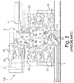
- Figures 1 and 2 illustrate such a recto-verso printing press that is adapted to carry out simultaneous recto-verso printing of sheets, as typically used for the production of banknotes and like security documents, which printing press is designated globally by reference numeral 100.
- Such printing press is in particular marketed by the present Applicant under the product designation Super Simultan® IV.
- the basic configuration of the printing press 100 shown in Figures 1 and 2 is similar to that shown and discussed with reference to Figure 1 of International PCT Publication No. WO 2007/042919 A2 .
- This printing press 100 comprises a printing unit 2, which is specifically adapted to perform simultaneous recto-verso printing of the sheets (according to the so-called Simultan-offset printing principle) and comprises, as is typical in the art, two blanket cylinders (or printing cylinders) 5, 6 rotating in the direction indicated by the arrows and between which the sheets are fed to receive multicolour impressions.
- blanket cylinders 5, 6 are three-segment cylinders which are supported between a pair of side frames designated by reference numeral 20.
- the blanket cylinders 5, 6 receive and collect different ink patterns in their respective colours from plate cylinders 15 and 16 (four on each side) which are distributed around a portion of the circumference of the blanket cylinders 5, 6.
- plate cylinders 15 and 16 which each carry a corresponding printing plate, are themselves inked by corresponding inking apparatuses 25 and 26, respectively.
- the two groups of inking apparatuses 25, 26 are advantageously supported in two inking carriages 21, 22 that can be moved toward or away from the centrally-located plate cylinders 15, 16 and blanket cylinders 5, 6.
- each printing plate is wrapped around the corresponding plate cylinder 15, 16 and clamped at its leading end and trailing end by a suitable plate clamping system, which plate clamping system is located in a corresponding cylinder pit of the plate cylinder (see e.g. International (PCT) Publications Nos. WO 2013/001518 A1 , WO 2013/001009 A1 and WO 2013/001010 A2 , which are also incorporated herein by reference in their entirety).
- PCT International
- Sheets are fed from a sheet feeder 1 onto a feeder table 1* locate next to the printing unit 2 (on the right-hand side in Figures 1 and 2 ) to a succession of transfer cylinders 9, 8', 10 (three cylinders in this example) placed upstream of the blanket cylinders 5, 6. While being transported by the transfer cylinder 8', the sheets receive a first impression on one side of the sheets using an additional printing group, the transfer cylinder 8' fulfilling the additional function of impression cylinder.
- This additional printing group consists of, in addition to the transfer cylinder 8', a blanket cylinder 8 (a two-segment cylinder in this example) that collects inks from two plate cylinders 18 that are inked by corresponding inking apparatuses 28.
- the inking apparatuses 28 are advantageously supported in an inking carriage 24 that can be moved toward or away from the plate cylinders 18 and blanket cylinder 8.
- the sheets that are printed by means of the additional printing group are first dried/cured by a drying/curing unit (designated by reference numeral 50 in Figure 2 ) while being transported by the sheet transfer cylinder 8' before being transferred to the downstream-located main printing group.
- the sheets are transferred onto the surface of blanket cylinder 5 where a leading edge of each sheet is held by appropriate gripper means located in cylinder pits between each segment of the blanket cylinder 5.
- Each sheet is thus transported by the blanket cylinder 5 to the printing nip between the blanket cylinders 5 and 6 where simultaneous recto-verso printing occurs.
- the printed sheets are then transferred, as known in the art, to a sheet conveying system 3 (such as a chain gripper system with spaced-apart gripper bars) for delivery in a sheet delivery unit 4 comprising multiple (e.g. three) delivery pile units.
- Reference numeral 31 in Figure 2 designates a pair of chain wheels located at the upstream end of the sheet conveying system 3.
- first and second transfer cylinders or drums 11, 12, such as suction drums or cylinders, are interposed between the sheet conveying system 3 and the blanket cylinder 5.
- These first and second transfer cylinders 11, 12 are optional (and could therefore be omitted) and are designed to carry out inspection of the sheets on the recto and verso sides as described for instance in International application No. WO 2007/105059 A1 .
- Reference numerals 61, 62 in Figure 2 designate corresponding inspection cameras (such as line-scan cameras) that cooperate with cylinder or drums 11, 12.
- the printing press of Figures 1 and 2 is especially used for the purpose of printing multicolour patterns with a very high colour-to-colour register.
- Such multicolour patterns can in particular be combined with a micro-optical structure (such as a micro-lens structure) to create optically-variable effects as for instance disclosed in International Publications Nos. WO 2007/020048 A2 , WO 2014/039476 A1 and WO 2014/085290 A1 , which publications are incorporated herein by reference.
- the relevant micro-optical structures are typically applied in a separate and dedicated process, in particular in combination with transparent windows that are formed in the substrate material, whether prior to or during the formation of the relevant micro-optical structures.
- Known processes for creating such micro-optical structures are disclosed for instance in European Patent Publication No. EP 1 878 584 A2 and International Publications Nos. WO 94/27254 A1 , WO 2007/020048 A2 , WO 2014/125454 A1 , WO 2015/022612 A1 and WO 2015/107488 A1 , which publications are likewise incorporated herein by reference.
- a general aim of the invention is to improve the known printing presses of the aforementioned type.
- an aim of the present invention is to provide such a printing press that allows to achieve high register between micro-optical structures to be provided on the substrate material and the printed patterns to be printed in combination with such micro-optical structures.
- Another aim of the present invention is to provide such a printing press where machine operability and accessibility are not compromised.
- a printing press adapted to carry out printing on a sheet-like or web-like substrate, in particular for the production of security documents such as banknotes, comprising a printing unit designed to print a first side and/or a second side of the substrate.
- the printing press further comprises an in-line casting device adapted to apply a layer of material acting as an optical medium on a portion of the first or second side of the substrate and to replicate and form a micro-optical structure in the layer of material acting as optical medium.
- the printing unit is adapted to print at least one printed pattern on the first or second side of the substrate in register with the micro-optical structure.
- the in-line casting device comprises at least one screen-printing unit acting as application unit for applying at least a part of the layer of material acting as optical medium.
- more than one screen-printing unit could be provided, especially if the quantity of material acting as the optical medium is to be increased.
- Other processes than screen printing could furthermore be contemplated to apply the relevant material acting as optical medium, it being however to be appreciated that screen printing remains a preferred process in the context of the invention.
- An alternative may for instance consist in using a flexographic-printing unit as the application unit.
- the in-line casting device may advantageously comprise at least one embossing cylinder acting as carrier supporting a replicating medium designed to replicate and form the micro-optical structure in the layer of material acting as optical medium.
- the aforementioned embossing cylinder could in particular be located immediately after the aforementioned application unit.
- the printing press could further comprise a washing device that can selectively be brought in contact with the embossing cylinder during maintenance operations to clean the surface of the embossing cylinder.
- a washing device that can selectively be brought in contact with the embossing cylinder during maintenance operations to clean the surface of the embossing cylinder. This would be particularly advantageous in facilitating removal of residues of the material used to form the micro-optical structure.
- the aforementioned embossing cylinder could further act as counter-pressure cylinder and cooperate with a cylinder of the printing unit acting as blanket cylinder and cooperating with one or more associated plate cylinders to apply the at least one printed pattern on a side of the substrate which is opposite to the side of the substrate where the micro-optical structure is replicated.
- This solution ensures highly optimal register accuracy between the print and the associated micro-optical structure.
- the printing press could advantageously be designed as a sheet-fed printing press adapted to carry out printing on individual sheets, wherein transfer of the sheets between the in-line casting device and the printing unit is carried out exclusively from cylinder to cylinder via cooperating cylinder grippers, which solution ensure optimal register accuracy between the print and the associated micro-optical structure.
- the in-line casting device could further be provided with at least one drying/curing unit (preferably a UV-curing unit such as a UV-LED curing unit) to dry or cure the layer of material acting as optical medium during and/or following replication of the micro-optical structure in the layer of material acting as optical medium.
- a drying/curing unit preferably a UV-curing unit such as a UV-LED curing unit
- drying/curing unit located to dry or cure the layer of material acting as optical medium from the side of the substrate which is opposite to the side of the substrate where the micro-optical structure is replicated, especially while the substrate is still being processed on the aforementioned embossing cylinder (in which case the drying/curing unit is to be located about a portion of the circumference of the embossing cylinder.
- a drying/curing unit could be located to dry or cure the layer of material acting as optical medium from the side of the substrate where the micro-optical structure is replicated, especially while the substrate is being transported by a transfer cylinder located immediately after the aforementioned embossing cylinder (in which case the drying/curing unit is to be located about a portion of the circumference of this transfer cylinder).
- the printing press of the invention can in particular be of a type where the printing unit is designed to operate as an offset printing unit, especially a Simultan-type offset printing unit for the simultaneous recto-verso printing of the substrate.
- the micro-optical structure is replicated by the in-line casting device upstream of a location where the printed pattern is printed by the printing unit.
- the in-line casting device could however be provided at any appropriate location in the printing press, be it after the relevant printing unit or between two printing units, or even form an integral part of a printing unit.
- the expression “printing cylinder(s)” will be used to designate the relevant cylinders of the main printing group and of any additional printing group that directly cooperate with the first and second sides of the substrates (e.g. sheets) to transfer printing patterns thereon.
- This expression is however interchangeable with the expression “blanket cylinder”, it being to be understood that the relevant printing cylinders each carry a number of printing blankets.
- first side designates the side of the sheets that is designated by reference I
- second side designates the side of the sheets that is designated by reference II.
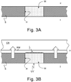
- FIGS 3A-B schematically illustrate an example of a substrate S that is provided with an opening (or through-hole) H extending through the substrate S.
- This opening H is preferably filled by a suitable filling material, which material is preferably substantially transparent, so as to form a transparent or substantially transparent window W visible from both sides I, II of the substrate S.
- a suitable filling material which material is preferably substantially transparent, so as to form a transparent or substantially transparent window W visible from both sides I, II of the substrate S.
- the particular shape and geometry of the opening H and resulting window W may be varied depending on the design requirements.
- the cross-sectional shape of the opening H could also be different from the depicted example.
- side II of the substrate S is first provided in the relevant portion of the substrate S with a layer of material acting as an optical medium (for instance by means of a suitable screen-printing unit as discussed hereafter) before being brought into contact with and pressed against the surface of a replicating medium RM that is provided with a corresponding replicating structure (formed as a recessed structure in the surface of the replicating medium RM). Any desired shape and geometry could be imparted to the replicating structure in order to form the desired micro-optical structure L.
- the replicating medium RM is conveniently carried by a suitable carrier CR, especially a cylinder acting as embossing cylinder as described hereinafter.
- the relevant material acting as optical medium is subjected to a drying or curing process (especially a UV-curing process).
- a drying or curing process especially a UV-curing process.
- This is preferably carried out, as schematically illustrated in Figure 3B , while the substrate S is still in contact with the replicating medium RM, advantageously by subjecting the substrate S and the relevant material acting as optical medium to UV radiation from the first side I of the substrate, through the window portion W.
- the invention is equally applicable to other types of substrates than the one illustrated in Figures 3A-B , especially polymer or hybrid substrates as for instance described in International Publication No. WO 2014/125454 A1 .
- the illustrations of Figures 3A-B are therefore by no way limiting the application scope of the present invention and the substrate material can be any suitable substrate material that can be used as printable material, such as paper, polymer, or combinations thereof.
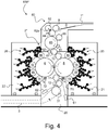
- Figure 4 schematically shows a partial side view of a printing unit, designated by reference numeral 2*, of a printing press 100* in accordance with a first embodiment of the invention.
- the printing press 100* comprises a main printing group consisting of elements 5, 6, 15, 16, 25, 26, including first and second printing cylinders 5, 6 cooperating with one another to form a first printing nip between the first and second printing cylinders 5, 6 where the first and second sides I, II of the sheets S are simultaneously printed, the first printing cylinder 5 acting as a sheet conveying cylinder of the main printing group.
- the configuration of the main printing group is as such identical to that of the main printing group illustrated in Figures 1 and 2 .
- printing cylinders 5, 6 are likewise three-segment cylinders which are supported between a pair of side frames 20.
- the two sets of inking apparatuses 25, 26 are preferably supported in two retractable inking carriages 21, 22 that can be moved toward or away from the centrally-located plate cylinders 15, 16 and printing cylinders 5, 6.
- the in-line casting device 80 depicted in Figure 4 is of the type comprising a screen-printing unit 82, 82a, 84, namely a printing unit comprising a rotary screen cylinder 82 inside which is provided a squeegee device 82a, which rotary screen cylinder 82 cooperates with an impression cylinder 84 onto which the sheets S are fed in succession from the transfer cylinder 9 at the infeed.
- the sheets S are transferred in succession to the impression cylinder 84 which supports the first side I of the sheets S and the rotary screen cylinder 82 is brought in contact with the second side II of the sheets S.
- the screen-printing unit 82, 82a, 84 is adapted to apply a layer of material acting as an optical medium on a portion of the second side II of the sheets S (for instance on a window-forming region W formed in the substrate S as depicted in Figures 3A-3B ).
- the relevant material could be any suitable material, especially a transparent polymer material that is preferably curable by UV radiation.
- the screen-printing unit 82, 82a, 84 could alternatively be designed to apply a layer of material acting as the optical medium on a portion of the first side I of the sheets S (for instance on a window-forming region W formed in the substrate S as depicted in Figures 3A-3B , however on side I rather than on side II).
- the aforementioned screen-printing unit 82, 82a, 84 is designed to act a first application unit for applying the required layer of material where the micro-optical structure is to be replicated.
- the configuration and operation of the screen-printing unit 82, 82a, 84 is known as such in the art and does not need to be described in detail.
- At least one embossing cylinder 85 Downstream of the impression cylinder 84, there is preferably provided at least one embossing cylinder 85 which cooperates with the second side II of the sheets S, i.e. the side where the layer of material acting as optical medium was applied by the screen-printing unit 82, 82a, 84.
- This embossing cylinder 85 preferably carries on its circumference a replicating medium RM (as schematically illustrated in Figure 3B ) designed to replicate a micro-optical structure L, such as but not limited to a field of micro-lenses, into the layer of material applied on the sheets S.
- the screen-printing unit 82, 82a, 84 should be adapted to supply a sufficient amount of material to fill the recessed portion of the replicating medium RM.
- a pressure roller or cylinder 86 is furthermore advantageously provided about the circumference of the embossing cylinder 85 in order to cooperate with the first side I of the sheets S and press the sheets S against the circumference of the embossing cylinder 85 (and the surface of the replicating medium RM located thereon), thereby ensuring proper replication of the micro-optical structure L into the layer of material acting as optical medium.
- the in-line casting device 80 further comprises a first drying/curing unit 51 located about a portion of the circumference of the embossing cylinder 85, downstream of the pressure roller or cylinder 86, to dry or cure the layer of material acting as optical medium while the sheets S are still being processed and pressed against the circumference of the embossing cylinder 85 and the surface of the replicating medium RM located thereon, thereby ensuring optimal replication and formation of the desired micro-optical structure L.
- the drying/curing operation is carried out from the first side I of the sheets S, which is especially adequate in the event that the micro-optical structure L is replicated on top of a window-forming portion W as schematically illustrated in Figure 3B .
- the in-line casting device 80 could be provided with a (second) drying/curing unit 52 located about a portion of the circumference of a transfer cylinder 87 that is located immediately after the embossing cylinder 85 as depicted in Figure 4 .
- a drying/curing operation is carried out from the second side II of the sheets S, where the micro-optical structure L has been replicated.
- drying/curing units 51, 52 could advantageously be UV-curing units, especially UV-LED curing units, in which case the relevant layer of material acting as optical medium evidently has to be a UV-curable material.
- the sheets S are transferred to the downstream-located printing unit 2*, namely to the sheet transfer cylinder 10.
- the sheets S are initially provided with micro-optical structures L on side II and then receive first and second impressions on both sides I, II, which impressions are performed simultaneously at the printing nip between the first and second printing cylinders 5, 6 of the main printing group. It will also be appreciated that transfer of the sheets S from the in-line casting device 80 to the printing unit 2* is carried out exclusively from cylinder to cylinder via cooperating cylinder grippers. Optimal register accuracy between the micro-optical structures L that are replicated by means of the embossing cylinder 85 and the impressions performed by the printing unit 2* is thereby guaranteed.
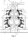
- Figure 5 schematically shows a partial side view of a printing unit, designated by reference numeral 2**, of a printing press 100** in accordance with a second embodiment of the invention.
- This printing press 100** shares a number of common features with the first embodiment of Figure 4 , in particular the same basic components 5, 6, 15, 16, 25, 26 constitutive of the main printing group and the same basic components 82, 82a, 84, 85, 86, 87, 51, 52 constitutive of the in-line casting device 80.
- the difference between this second embodiment and the first embodiment resides in that an additional printing group is interposed between the in-line casting device 80 and the main printing group.
- the printing press 100** of Figure 5 comprises third and fourth printing cylinders 7, 8 cooperating with one another to form a second printing nip between the third and fourth printing cylinders 7, 8 where the first and second sides I, II of the sheets S are simultaneously printed, the third printing cylinder 7 acting as a sheet conveying cylinder of the additional printing group.
- These two sets of inking apparatuses 27, 28 are likewise preferably supported in two retractable inking carriages 23, 24 that can be moved toward or away from the centrally-located plate cylinders 17, 18 and printing cylinders 7, 8.
- the sets of inking apparatus 25, 27 on the right side of the printing unit 2 and/or the sets of inking apparatus 26, 28 on the left side of the printing unit 2 could be supported in one and a same inking carriage (one on each side).
- the additional printing group 7, 8, 17, 18, 27, 28 is placed upstream of and above the main printing group 5, 6, 15, 16, 25, 26, the first and second printing cylinders 5, 6, on the one hand, and the third and fourth printing cylinders 7, 8, on the other hand, being advantageously aligned along two horizontal planes.
- the main printing group 5, 6, 15, 16, 25, 26 and the additional printing group 7, 8, 17, 18, 27, 28 are coupled to one another by means of an intermediate sheet conveying system comprising, in the illustrated embodiment, first to third sheet-transfer cylinders 10', 10", 10''' interposed between the first and third printing cylinders 5, 7. More precisely, the sheets printed in the additional printing group 7, 8, 17, 18, 27, 28 are transferred from the third printing cylinder 7 in succession to the first sheet-transfer cylinders 10', to the second sheet-transfer cylinders 10", to the third sheet-transfer cylinder 10"', and then to the first printing cylinder 5 of the main printing group.
- an intermediate sheet conveying system comprising, in the illustrated embodiment, first to third sheet-transfer cylinders 10', 10", 10''' interposed between the first and third printing cylinders 5, 7. More precisely, the sheets printed in the additional printing group 7, 8, 17, 18, 27, 28 are transferred from the third printing cylinder 7 in succession to the first sheet-transfer cylinders 10', to the second sheet-transfer cylinder
- the sheets are preferably dried/cured by third and fourth drying/curing units 55, 56.
- the third drying/curing unit 55 advantageously cooperates with the first sheet-transfer cylinder 10', i.e. the sheet-transfer cylinder located immediately downstream of the third printing cylinder 7, and the fourth drying/curing unit 56 cooperates with the second sheet-transfer cylinder 10".
- the drying/curing units 55, 56 are advantageously UV curing units, preferably UV-LED curing units.
- Drying/curing of the second side II of the sheets could alternatively be performed directly onto the third printing cylinder 7, provided suitable measures are taken to ensure that the drying/curing unit does not degrade the performance or usability of the printing blankets on the third printing cylinder 7.
- the sheets S are accordingly fed in succession from the sheet feeder (not shown in Figure 5 ) onto the feeder table 1* where they are once again conventionally aligned before being fed to the sheet transfer cylinder 9 at the infeed.
- the sheets are then fed in succession by the sheet transfer cylinder 9 to and through the in-line casting device 80 (via cylinders 84, 85 and 87) to the transfer cylinder 10, to the third printing cylinder 7 of the additional printing group and then to the first printing cylinder 5 of the main printing group via the three intermediate sheet transfer cylinders 10' to 10"'.
- the sheets S are initially provided with micro-optical structures L on side II and then receive first and second impressions on both sides I, II, which impressions are performed simultaneously at the printing nip between the third and fourth printing cylinders 7, 8 of the additional printing group and at the printing nip between the first and second printing cylinders 5, 6 of the main printing group. It will likewise also be appreciated that transfer of the sheets S from the in-line casting device 80 to the printing unit 2** is carried out exclusively from cylinder to cylinder via cooperating cylinder grippers. Optimal register accuracy between the micro-optical structures L that are replicated by means of the embossing cylinder 85 and the impressions performed by the printing unit 2** is once again guaranteed.
- Figure 6 schematically shows a partial side view of a printing unit, designated by reference numeral 2***, of a printing press 100*** in accordance with a third embodiment of the invention.
- the additional printing group is designed in this case to print only the second side II of the sheets S (and comprises three plate cylinders 18 and associated inking apparatuses 28 instead of two) and in that (ii) the in-line casting device, designated by reference numeral 80* in Figure 6 , is adapted to apply a layer of material acting as the optical medium on a portion of the first side I of the sheets S (rather than on the second side II as in the embodiments of Figures 4 and 5 ).
- the embossing cylinder 85 is arranged so as to act as counter-pressure cylinder for the (third) printing cylinder 8 of the additional printing group.
- in-line casting of the micro-optical structure L is performed from and on the first side I of the sheets S and a printed pattern is printed on the second side II of the sheets S, while the sheets S are still being supported on the embossing cylinder 85, i.e. without this involving any sheet transfer between the in-line casting of the micro-optical structure L and the printing of the printed pattern.
- Operation of the in-line casting device 80* (and of the components thereof 82, 82a, 84, 85, 86) is basically identical to that of the in-line casting device 80 depicted in Figures 4 and 5 , except that the micro-optical structure L is ultimately formed on the first side I of the sheets S.
- an additional transfer cylinder 9' is provided downstream of the transfer cylinder 9 at the infeed and that transfer cylinder 87 has been omitted as the sheets S can be transferred directly from the embossing cylinder 85 to the transfer cylinder 10'.
- Transfer cylinder 10" is furthermore a double-sized cylinder in this third embodiment to increase space between the additional printing group and the main printing group, thereby allowing the integration of a third plate cylinder 18 and associated inking apparatus 28 in the additional printing group.
- transfer cylinder 87 has been omitted, so has the associated drying/curing unit 52, as well as the downstream-located sheet transfer cylinder 10. This being said, an additional drying/curing unit could be provided about the circumference of the embossing cylinder 85, downstream of the printing cylinder 8 and upstream of the sheet transfer cylinder 10'.
- the sheets S are accordingly fed in succession from the sheet feeder (not shown in Figure 6 ) onto the feeder table 1* where they are once again conventionally aligned before being fed to the sheet transfer cylinder 9 at the infeed.
- the sheets are then fed in succession by the sheet transfer cylinder 9 to the additional sheet transfer cylinder 9', through the in-line casting device 80* (via cylinders 84 and 85), and then to the first printing cylinder 5 of the main printing group via the three intermediate sheet transfer cylinders 10' to 10"'.
- the sheets S are initially provided with micro-optical structures L on side I and immediately receive a first impression on side II thanks to the additional printing unit. Further impressions are then formed on both sides I, II of the sheets S by means of the main printing group, which impressions are performed simultaneously at the printing nip between the first and second printing cylinders 5, 6 of the main printing group.
- the in-line casting device 80* is designed in this case to be an integral part of the printing unit 2*** (the same applies in respect of the in-line casting device 80** depicted in Figure 7 which likewise forms an integral part of the printing unit 2****). Highly optimal register accuracy between the micro-optical structures L that are replicated by means of the embossing cylinder 85 and the impressions performed by the printing unit 2*** is therefore guaranteed.
- Figure 7 schematically shows a partial side view of a printing unit, designated by reference numeral 2****, of a printing press 100**** in accordance with a fourth embodiment of the invention.
- the sole difference between this fourth embodiment and the third embodiment resides in that the in-line casting device, designated by reference numeral 80**, is making use of a flexographic-printing unit 83, 83a, 84* to applying at least a part of the layer of material acting as the optical medium, instead of the screen-printing unit 82, 82a, 84 depicted in Figure 6 .
- This flexographic-printing unit 83, 83a, 84* includes a plate-cylinder 83, which cooperates with an impression cylinder 84*.
- the plate cylinder 83 carries a suitable flexographic printing plate (with relief portions corresponding in shape and position to the area on the sheets S where the layer of material is to be applied) which cooperates with an anilox roller 83a equipped with an associated supply chamber where the material to be applied is supplied.
- Flexographic-printing units are known as such in the art, especially for varnishing applications (see e.g. International PCT Publication No. WO 2011/145028 A1 ).
- the main printing group 5, 6, 15, 16, 25, 26 in the embodiments of Figures 5 to 7 could be omitted altogether and the additional printing group 7, 8, 17, 18, 27, 28, respectively 8, 18, 28 used exclusively for the purpose of printing the desired pattern in register with the micro-optical structure L.
- the integrated solution depicted in Figures 6 and 7 could in particular be conceived as a combined printing and in-line casting platform or module that could serve as a stand-alone printing press or as modular printing unit that could be combined with additional printing units if necessary.
- the printing presses 100* of Figure 4 and 100** of Figure 5 can also conveniently equipped, as illustrated, with automatic blanket washing devices 71, 72, 73, 74 adapted to clean the surface of the first, second, third and fourth printing cylinders 5, 6, 7, 8, respectively, during maintenance operations.
- the printing presses 100*** of Figure 6 and 100**** of Figure 7 can likewise be equipped, as illustrated, with automatic blanket washing devices 71, 72, 74 adapted to clean the surface of the first, second and third printing cylinders 5, 6, 8, respectively, during maintenance operations.
- a suitable automatic washing device 88 could be provided to clean the surface of the embossing cylinder 85 during maintenance operations (which automatic washing device 88 could also be contemplated in the context of the embodiments of Figures 4 and 5 ).
- the in-line casting device could be adapted to apply a layer of material acting as an optical medium on a portion of either the first or second side of the substrate and to replicate and form the micro-optical structure accordingly.
- the configurations of the in-line casting devices 80, 80*, 80** shown in Figures 4 to 7 are only illustrative of possible machine configurations.
Landscapes
- Engineering & Computer Science (AREA)
- Mechanical Engineering (AREA)
- Printing Methods (AREA)
- Supply, Installation And Extraction Of Printed Sheets Or Plates (AREA)
- Rotary Presses (AREA)
- Inking, Control Or Cleaning Of Printing Machines (AREA)
- Credit Cards Or The Like (AREA)
Abstract
Description
- The present invention generally relates to a printing press - especially an offset printing press - adapted to carry out printing on a sheet-like or web-like substrate, in particular for the production of security documents such as banknotes, comprising a printing unit designed to print a first side and/or a second side of the substrate.
- Offset printing presses for the production of security documents such as banknotes are known as such in the art, in particular from European Patent Publication No.
EP 0 949 069 A1 and International PCT Publications Nos.WO 2007/042919 A2 ,WO 2007/105059 A1 ,WO 2007/105061 A1 ,WO 2008/099330 A2 andWO 2016/071870 A1 , which publications are all incorporated herein by reference in their entirety. - International PCT Publication No.
WO 2007/042919 A2 in particular discloses a recto-verso offset printing press adapted for simultaneous recto-verso printing of sheets that further comprises an additional printing group placed upstream of a main printing group of the printing press. -
Figures 1 and2 illustrate such a recto-verso printing press that is adapted to carry out simultaneous recto-verso printing of sheets, as typically used for the production of banknotes and like security documents, which printing press is designated globally byreference numeral 100. Such printing press is in particular marketed by the present Applicant under the product designation Super Simultan® IV. The basic configuration of theprinting press 100 shown inFigures 1 and2 is similar to that shown and discussed with reference toFigure 1 of International PCT Publication No.WO 2007/042919 A2 . - This
printing press 100 comprises aprinting unit 2, which is specifically adapted to perform simultaneous recto-verso printing of the sheets (according to the so-called Simultan-offset printing principle) and comprises, as is typical in the art, two blanket cylinders (or printing cylinders) 5, 6 rotating in the direction indicated by the arrows and between which the sheets are fed to receive multicolour impressions. In this example,blanket cylinders reference numeral 20. Theblanket cylinders plate cylinders 15 and 16 (four on each side) which are distributed around a portion of the circumference of theblanket cylinders plate cylinders apparatuses apparatuses carriages plate cylinders blanket cylinders - As is known in the art, each printing plate is wrapped around the
corresponding plate cylinder WO 2013/001518 A1 ,WO 2013/001009 A1 andWO 2013/001010 A2 , which are also incorporated herein by reference in their entirety). - Sheets are fed from a
sheet feeder 1 onto a feeder table 1* locate next to the printing unit 2 (on the right-hand side inFigures 1 and2 ) to a succession oftransfer cylinders 9, 8', 10 (three cylinders in this example) placed upstream of theblanket cylinders plate cylinders 18 that are inked by corresponding inkingapparatuses 28. The inkingapparatuses 28 are advantageously supported in aninking carriage 24 that can be moved toward or away from theplate cylinders 18 andblanket cylinder 8. The sheets that are printed by means of the additional printing group are first dried/cured by a drying/curing unit (designated byreference numeral 50 inFigure 2 ) while being transported by the sheet transfer cylinder 8' before being transferred to the downstream-located main printing group. - In the example of
Figures 1 and2 , the sheets are transferred onto the surface ofblanket cylinder 5 where a leading edge of each sheet is held by appropriate gripper means located in cylinder pits between each segment of theblanket cylinder 5. Each sheet is thus transported by theblanket cylinder 5 to the printing nip between theblanket cylinders sheet delivery unit 4 comprising multiple (e.g. three) delivery pile units.Reference numeral 31 inFigure 2 designates a pair of chain wheels located at the upstream end of thesheet conveying system 3. - In the example of
Figures 1 and2 , first and second transfer cylinders ordrums sheet conveying system 3 and theblanket cylinder 5. These first andsecond transfer cylinders WO 2007/105059 A1 .Reference numerals Figure 2 designate corresponding inspection cameras (such as line-scan cameras) that cooperate with cylinder ordrums - The printing press of
Figures 1 and2 is especially used for the purpose of printing multicolour patterns with a very high colour-to-colour register. Such multicolour patterns can in particular be combined with a micro-optical structure (such as a micro-lens structure) to create optically-variable effects as for instance disclosed in International Publications Nos.WO 2007/020048 A2 ,WO 2014/039476 A1 andWO 2014/085290 A1 , which publications are incorporated herein by reference. - The relevant micro-optical structures are typically applied in a separate and dedicated process, in particular in combination with transparent windows that are formed in the substrate material, whether prior to or during the formation of the relevant micro-optical structures. Known processes for creating such micro-optical structures are disclosed for instance in European Patent Publication No.
EP 1 878 584 A2WO 94/27254 A1 WO 2007/020048 A2 ,WO 2014/125454 A1 ,WO 2015/022612 A1 andWO 2015/107488 A1 , which publications are likewise incorporated herein by reference. - Application of a separate and dedicated process to create the necessary micro-optical structures is however cumbersome and adds up to the complexity and cost of the production of the relevant security features and documents incorporating the same. There is therefore a need for an improved solution, especially such a solution that streamlines and simplifies the production of documents that are to be provided with security elements incorporating micro-optical structures.
- A general aim of the invention is to improve the known printing presses of the aforementioned type.
- More precisely, an aim of the present invention is to provide such a printing press that allows to achieve high register between micro-optical structures to be provided on the substrate material and the printed patterns to be printed in combination with such micro-optical structures.
- Another aim of the present invention is to provide such a printing press where machine operability and accessibility are not compromised.
- These aims are achieved thanks to the printing press defined in the claims. In particular there is provided a printing press adapted to carry out printing on a sheet-like or web-like substrate, in particular for the production of security documents such as banknotes, comprising a printing unit designed to print a first side and/or a second side of the substrate. According to the invention, the printing press further comprises an in-line casting device adapted to apply a layer of material acting as an optical medium on a portion of the first or second side of the substrate and to replicate and form a micro-optical structure in the layer of material acting as optical medium. Furthermore, the printing unit is adapted to print at least one printed pattern on the first or second side of the substrate in register with the micro-optical structure.
- In accordance with a preferred embodiment of the invention, the in-line casting device comprises at least one screen-printing unit acting as application unit for applying at least a part of the layer of material acting as optical medium. In the context of the present invention, more than one screen-printing unit could be provided, especially if the quantity of material acting as the optical medium is to be increased. Other processes than screen printing could furthermore be contemplated to apply the relevant material acting as optical medium, it being however to be appreciated that screen printing remains a preferred process in the context of the invention. An alternative may for instance consist in using a flexographic-printing unit as the application unit.
- According to another preferred embodiment of the invention, the in-line casting device may advantageously comprise at least one embossing cylinder acting as carrier supporting a replicating medium designed to replicate and form the micro-optical structure in the layer of material acting as optical medium. In this context, it is particularly advantageous to additionally provide at least one pressure cylinder or roller cooperating with the embossing cylinder to press the substrate against the replicating medium, which ensures optimal replication and formation of the relevant micro-optical structures. The aforementioned embossing cylinder could in particular be located immediately after the aforementioned application unit.
- By way of preference, the printing press could further comprise a washing device that can selectively be brought in contact with the embossing cylinder during maintenance operations to clean the surface of the embossing cylinder. This would be particularly advantageous in facilitating removal of residues of the material used to form the micro-optical structure.
- In accordance with a particularly preferred embodiment of the invention, the aforementioned embossing cylinder could further act as counter-pressure cylinder and cooperate with a cylinder of the printing unit acting as blanket cylinder and cooperating with one or more associated plate cylinders to apply the at least one printed pattern on a side of the substrate which is opposite to the side of the substrate where the micro-optical structure is replicated. This solution ensures highly optimal register accuracy between the print and the associated micro-optical structure.
- Furthermore, the printing press could advantageously be designed as a sheet-fed printing press adapted to carry out printing on individual sheets, wherein transfer of the sheets between the in-line casting device and the printing unit is carried out exclusively from cylinder to cylinder via cooperating cylinder grippers, which solution ensure optimal register accuracy between the print and the associated micro-optical structure.
- According to a further embodiment of the invention, the in-line casting device could further be provided with at least one drying/curing unit (preferably a UV-curing unit such as a UV-LED curing unit) to dry or cure the layer of material acting as optical medium during and/or following replication of the micro-optical structure in the layer of material acting as optical medium.
- This could advantageously be performed by means of a drying/curing unit located to dry or cure the layer of material acting as optical medium from the side of the substrate which is opposite to the side of the substrate where the micro-optical structure is replicated, especially while the substrate is still being processed on the aforementioned embossing cylinder (in which case the drying/curing unit is to be located about a portion of the circumference of the embossing cylinder.
- Alternatively, or in addition to the above measures, a drying/curing unit could be located to dry or cure the layer of material acting as optical medium from the side of the substrate where the micro-optical structure is replicated, especially while the substrate is being transported by a transfer cylinder located immediately after the aforementioned embossing cylinder (in which case the drying/curing unit is to be located about a portion of the circumference of this transfer cylinder).
- The printing press of the invention can in particular be of a type where the printing unit is designed to operate as an offset printing unit, especially a Simultan-type offset printing unit for the simultaneous recto-verso printing of the substrate.
- By way of preference, the micro-optical structure is replicated by the in-line casting device upstream of a location where the printed pattern is printed by the printing unit. Within the scope of the present invention, the in-line casting device could however be provided at any appropriate location in the printing press, be it after the relevant printing unit or between two printing units, or even form an integral part of a printing unit.
- Further advantageous embodiments of the invention form the subject-matter of the dependent claims and are discussed below.
- Other features and advantages of the present invention will appear more clearly from reading the following detailed description of embodiments of the invention which are presented solely by way of non-restrictive examples and illustrated by the attached drawings in which:
-
Figure 1 is schematic illustration of recto-verso printing press exhibiting a configuration similar to that disclosed in International PCT Publication No.WO 2007/042919 A2 ; -
Figure 2 is a schematic partial side view of the printing unit of the printing press ofFigure 1 ; -
Figures 3A and 3B are schematic illustrations of a substrate that is provided with a micro-optical structure on top of a window-forming portion created in the substrate ; -
Figure 4 is a schematic partial side view of the printing unit of a printing press in accordance with a first embodiment of the invention ; -
Figure 5 is a schematic partial side view of the printing unit of a printing press in accordance with a second embodiment of the invention ; -
Figure 6 is a schematic partial side view of the printing unit of a printing press in accordance with a third embodiment of the invention ; and -
Figure 7 is a schematic partial side view of the printing unit of a printing press in accordance with a fourth embodiment of the invention. - The present invention will be described in the particular context of a sheet-fed recto-verso printing press exhibiting a (m)-over-(m) configuration (see embodiment of
Figure 4 where m equals 4), a (m+n)-over-(m+n) configuration (see embodiment ofFigure 5 where m, n respectively equal 4 and 2), or a (m)-over-(m+n) configuration (see embodiments ofFigures 6 and7 where m, n respectively equal 4 and 3). It shall be appreciated however that the invention is not limited to these particular printing press configurations, the number of plate cylinders being purely illustrative. This being said, the printing press configurations as shown inFigure 4 to 7 are of particular advantage as they allow very high colour-to-colour register accuracy. - In the context of the present invention, the expression "printing cylinder(s)" will be used to designate the relevant cylinders of the main printing group and of any additional printing group that directly cooperate with the first and second sides of the substrates (e.g. sheets) to transfer printing patterns thereon. This expression is however interchangeable with the expression "blanket cylinder", it being to be understood that the relevant printing cylinders each carry a number of printing blankets.
- The expression "first side" (designated by reference I) and "second side" (designated by reference II) are used in the following description to designate the two opposite sides of the sheets being printed. More precisely, in the illustrations of
Figures 4 and5 , the "first side" I designates the side of the sheets that is designated by the white triangles, while the "second side" II designates the side of the sheets that is designated by the black triangles. These expressions are however interchangeable. -
Figures 3A-B schematically illustrate an example of a substrate S that is provided with an opening (or through-hole) H extending through the substrate S. This opening H is preferably filled by a suitable filling material, which material is preferably substantially transparent, so as to form a transparent or substantially transparent window W visible from both sides I, II of the substrate S. The particular shape and geometry of the opening H and resulting window W may be varied depending on the design requirements. The cross-sectional shape of the opening H could also be different from the depicted example. - In accordance with the invention, one wishes to replicate a micro-optical structure L on one or the other side of the substrate S. More precisely, according to the illustrated example, one wishes to replicate a micro-optical structure L, such as a field of micro-lenses, on top of the window W, on the second side II of the substrate S. To this end, side II of the substrate S is first provided in the relevant portion of the substrate S with a layer of material acting as an optical medium (for instance by means of a suitable screen-printing unit as discussed hereafter) before being brought into contact with and pressed against the surface of a replicating medium RM that is provided with a corresponding replicating structure (formed as a recessed structure in the surface of the replicating medium RM). Any desired shape and geometry could be imparted to the replicating structure in order to form the desired micro-optical structure L.
- As schematically illustrated in
Figure 3B , the replicating medium RM is conveniently carried by a suitable carrier CR, especially a cylinder acting as embossing cylinder as described hereinafter. - Subsequent to, or preferably during the replication process, the relevant material acting as optical medium is subjected to a drying or curing process (especially a UV-curing process). This is preferably carried out, as schematically illustrated in
Figure 3B , while the substrate S is still in contact with the replicating medium RM, advantageously by subjecting the substrate S and the relevant material acting as optical medium to UV radiation from the first side I of the substrate, through the window portion W. - It should be appreciated that the invention is equally applicable to other types of substrates than the one illustrated in
Figures 3A-B , especially polymer or hybrid substrates as for instance described in International Publication No.WO 2014/125454 A1 . The illustrations ofFigures 3A-B are therefore by no way limiting the application scope of the present invention and the substrate material can be any suitable substrate material that can be used as printable material, such as paper, polymer, or combinations thereof. -
Figure 4 schematically shows a partial side view of a printing unit, designated byreference numeral 2*, of aprinting press 100* in accordance with a first embodiment of the invention. - The
printing press 100* comprises a main printing group consisting ofelements second printing cylinders second printing cylinders first printing cylinder 5 acting as a sheet conveying cylinder of the main printing group. The configuration of the main printing group is as such identical to that of the main printing group illustrated inFigures 1 and2 . In this embodiment,printing cylinders printing cylinders plate cylinders 15, respectively 16, which are distributed around a portion of the circumference of theprinting cylinders plate cylinders apparatuses apparatuses retractable inking carriages plate cylinders printing cylinders - In contrast to the configuration illustrated in
Figures 1 and2 , no additional printing group is provided upstream of the main printing group. Instead, an in-line casting device 80 is interposed between thetransfer cylinder 9 located at the infeed and thetransfer cylinder 10 that transfers the sheets to the main printing group, which in-line casting device 80 will now be described. - By way of preference, the in-
line casting device 80 depicted inFigure 4 (and inFigure 5 - see alsoFigure 6 where the in-line casting device is designated byreference numeral 80*) is of the type comprising a screen-printing unit rotary screen cylinder 82 inside which is provided asqueegee device 82a, whichrotary screen cylinder 82 cooperates with animpression cylinder 84 onto which the sheets S are fed in succession from thetransfer cylinder 9 at the infeed. More precisely, in according with this first embodiment, the sheets S are transferred in succession to theimpression cylinder 84 which supports the first side I of the sheets S and therotary screen cylinder 82 is brought in contact with the second side II of the sheets S. In this particular context, the screen-printing unit Figures 3A-3B ). The relevant material could be any suitable material, especially a transparent polymer material that is preferably curable by UV radiation. - As this will be appreciated from looking at the embodiment depicted in
Figure 6 , the screen-printing unit Figures 3A-3B , however on side I rather than on side II). - The aforementioned screen-
printing unit printing unit EP 0 723 864 A1 in the name of the present Applicant, which is incorporated herein by reference in its entirety. - In the illustration of
Figure 4 (andFigures 5 and 6 ), only one screen-printing unit is depicted. It should however be appreciated that multiple screen-printing units could be provided, which screen-printing units could cooperate with one and a same impression cylinder. Furthermore, while screen printing is a preferred process for applying the required material, other application processes could be contemplated. For instance, flexographic printing could be contemplated (see for instance the embodiment depicted inFigure 7 ). - Downstream of the
impression cylinder 84, there is preferably provided at least oneembossing cylinder 85 which cooperates with the second side II of the sheets S, i.e. the side where the layer of material acting as optical medium was applied by the screen-printing unit embossing cylinder 85 preferably carries on its circumference a replicating medium RM (as schematically illustrated inFigure 3B ) designed to replicate a micro-optical structure L, such as but not limited to a field of micro-lenses, into the layer of material applied on the sheets S. In that respect, the screen-printing unit - A pressure roller or
cylinder 86 is furthermore advantageously provided about the circumference of theembossing cylinder 85 in order to cooperate with the first side I of the sheets S and press the sheets S against the circumference of the embossing cylinder 85 (and the surface of the replicating medium RM located thereon), thereby ensuring proper replication of the micro-optical structure L into the layer of material acting as optical medium. - The in-
line casting device 80 further comprises a first drying/curing unit 51 located about a portion of the circumference of theembossing cylinder 85, downstream of the pressure roller orcylinder 86, to dry or cure the layer of material acting as optical medium while the sheets S are still being processed and pressed against the circumference of theembossing cylinder 85 and the surface of the replicating medium RM located thereon, thereby ensuring optimal replication and formation of the desired micro-optical structure L. In this context, it shall be understood that the drying/curing operation is carried out from the first side I of the sheets S, which is especially adequate in the event that the micro-optical structure L is replicated on top of a window-forming portion W as schematically illustrated inFigure 3B . - Alternatively, or in addition to the aforementioned drying/
curing unit 51, the in-line casting device 80 could be provided with a (second) drying/curingunit 52 located about a portion of the circumference of atransfer cylinder 87 that is located immediately after theembossing cylinder 85 as depicted inFigure 4 . In this case, it shall be understood that the drying/curing operation is carried out from the second side II of the sheets S, where the micro-optical structure L has been replicated. - The aforementioned drying/
curing units - Subsequent to the replication of the micro-optical structure L, the sheets S are transferred to the downstream-located
printing unit 2*, namely to thesheet transfer cylinder 10. - In accordance with this first embodiment, the sheets S are accordingly fed in succession from the sheet feeder (not shown in
Figure 4 ) onto the feeder table 1* where they are conventionally aligned before being fed to thesheet transfer cylinder 9 at the infeed. As illustrated, the sheets are fed in succession by thesheet transfer cylinder 9 to and through the in-line casting device 80 (viacylinders transfer cylinder 10 and then to thefirst printing cylinder 5 of the main printing group. - It will therefore be appreciated that the sheets S are initially provided with micro-optical structures L on side II and then receive first and second impressions on both sides I, II, which impressions are performed simultaneously at the printing nip between the first and
second printing cylinders line casting device 80 to theprinting unit 2* is carried out exclusively from cylinder to cylinder via cooperating cylinder grippers. Optimal register accuracy between the micro-optical structures L that are replicated by means of theembossing cylinder 85 and the impressions performed by theprinting unit 2* is thereby guaranteed. -
Figure 5 schematically shows a partial side view of a printing unit, designated byreference numeral 2**, of aprinting press 100** in accordance with a second embodiment of the invention. - This
printing press 100** shares a number of common features with the first embodiment ofFigure 4 , in particular the samebasic components basic components line casting device 80. The difference between this second embodiment and the first embodiment resides in that an additional printing group is interposed between the in-line casting device 80 and the main printing group. More precisely, theprinting press 100** ofFigure 5 comprises third andfourth printing cylinders 7, 8 cooperating with one another to form a second printing nip between the third andfourth printing cylinders 7, 8 where the first and second sides I, II of the sheets S are simultaneously printed, the third printing cylinder 7 acting as a sheet conveying cylinder of the additional printing group. Eachprinting cylinder 7, 8 collects inks from corresponding sets of two (n = 2)plate cylinders 17, respectively 18, that are inked by corresponding inkingapparatuses apparatuses retractable inking carriages plate cylinders printing cylinders 7, 8. - Alternatively, the sets of inking
apparatus printing unit 2 and/or the sets of inkingapparatus printing unit 2 could be supported in one and a same inking carriage (one on each side). - In the illustrated example, the
additional printing group main printing group second printing cylinders fourth printing cylinders 7, 8, on the other hand, being advantageously aligned along two horizontal planes. - The
main printing group additional printing group transfer cylinders third printing cylinders 5, 7. More precisely, the sheets printed in theadditional printing group transfer cylinders 10', to the second sheet-transfer cylinders 10", to the third sheet-transfer cylinder 10"', and then to thefirst printing cylinder 5 of the main printing group. - On their way to the
main printing group curing units curing unit 55 advantageously cooperates with the first sheet-transfer cylinder 10', i.e. the sheet-transfer cylinder located immediately downstream of the third printing cylinder 7, and the fourth drying/curing unit 56 cooperates with the second sheet-transfer cylinder 10". The drying/curing units - Drying/curing of the second side II of the sheets could alternatively be performed directly onto the third printing cylinder 7, provided suitable measures are taken to ensure that the drying/curing unit does not degrade the performance or usability of the printing blankets on the third printing cylinder 7.
- In accordance with this other embodiment, the sheets S are accordingly fed in succession from the sheet feeder (not shown in
Figure 5 ) onto the feeder table 1* where they are once again conventionally aligned before being fed to thesheet transfer cylinder 9 at the infeed. As illustrated, the sheets are then fed in succession by thesheet transfer cylinder 9 to and through the in-line casting device 80 (viacylinders transfer cylinder 10, to the third printing cylinder 7 of the additional printing group and then to thefirst printing cylinder 5 of the main printing group via the three intermediatesheet transfer cylinders 10' to 10"'. - It will therefore be appreciated that the sheets S are initially provided with micro-optical structures L on side II and then receive first and second impressions on both sides I, II, which impressions are performed simultaneously at the printing nip between the third and
fourth printing cylinders 7, 8 of the additional printing group and at the printing nip between the first andsecond printing cylinders line casting device 80 to theprinting unit 2** is carried out exclusively from cylinder to cylinder via cooperating cylinder grippers. Optimal register accuracy between the micro-optical structures L that are replicated by means of theembossing cylinder 85 and the impressions performed by theprinting unit 2** is once again guaranteed. -
Figure 6 schematically shows a partial side view of a printing unit, designated byreference numeral 2***, of aprinting press 100*** in accordance with a third embodiment of the invention. - This
printing press 100*** shares a number of common features with the second embodiment ofFigure 5 , in particular the samebasic components basic components transfer cylinders plate cylinders 18 and associated inkingapparatuses 28 instead of two) and in that (ii) the in-line casting device, designated byreference numeral 80* inFigure 6 , is adapted to apply a layer of material acting as the optical medium on a portion of the first side I of the sheets S (rather than on the second side II as in the embodiments ofFigures 4 and5 ). - Furthermore, in accordance with this third embodiment, the
embossing cylinder 85 is arranged so as to act as counter-pressure cylinder for the (third)printing cylinder 8 of the additional printing group. In other words, and in contrast to the first and second embodiments, in-line casting of the micro-optical structure L is performed from and on the first side I of the sheets S and a printed pattern is printed on the second side II of the sheets S, while the sheets S are still being supported on theembossing cylinder 85, i.e. without this involving any sheet transfer between the in-line casting of the micro-optical structure L and the printing of the printed pattern. This is even more favourable in terms of achieving a high register between the micro-optical structure L and the associated printed pattern as in-line casting of the micro-optical structure, on one side of the sheets S, and printing of the associated pattern, on the other side of the sheets S, are performed in a same step, without this involving any sheet transfer operation. - Operation of the in-
line casting device 80* (and of the components thereof 82, 82a, 84, 85, 86) is basically identical to that of the in-line casting device 80 depicted inFigures 4 and5 , except that the micro-optical structure L is ultimately formed on the first side I of the sheets S. It will be appreciated that an additional transfer cylinder 9' is provided downstream of thetransfer cylinder 9 at the infeed and thattransfer cylinder 87 has been omitted as the sheets S can be transferred directly from theembossing cylinder 85 to thetransfer cylinder 10'.Transfer cylinder 10" is furthermore a double-sized cylinder in this third embodiment to increase space between the additional printing group and the main printing group, thereby allowing the integration of athird plate cylinder 18 and associated inkingapparatus 28 in the additional printing group. - As
transfer cylinder 87 has been omitted, so has the associated drying/curing unit 52, as well as the downstream-locatedsheet transfer cylinder 10. This being said, an additional drying/curing unit could be provided about the circumference of theembossing cylinder 85, downstream of theprinting cylinder 8 and upstream of thesheet transfer cylinder 10'. - In accordance with this third embodiment, the sheets S are accordingly fed in succession from the sheet feeder (not shown in
Figure 6 ) onto the feeder table 1* where they are once again conventionally aligned before being fed to thesheet transfer cylinder 9 at the infeed. As illustrated, the sheets are then fed in succession by thesheet transfer cylinder 9 to the additional sheet transfer cylinder 9', through the in-line casting device 80* (viacylinders 84 and 85), and then to thefirst printing cylinder 5 of the main printing group via the three intermediatesheet transfer cylinders 10' to 10"'. - It will therefore be appreciated that the sheets S are initially provided with micro-optical structures L on side I and immediately receive a first impression on side II thanks to the additional printing unit. Further impressions are then formed on both sides I, II of the sheets S by means of the main printing group, which impressions are performed simultaneously at the printing nip between the first and
second printing cylinders line casting device 80* is designed in this case to be an integral part of theprinting unit 2*** (the same applies in respect of the in-line casting device 80** depicted inFigure 7 which likewise forms an integral part of theprinting unit 2****). Highly optimal register accuracy between the micro-optical structures L that are replicated by means of theembossing cylinder 85 and the impressions performed by theprinting unit 2*** is therefore guaranteed. -
Figure 7 schematically shows a partial side view of a printing unit, designated byreference numeral 2****, of aprinting press 100**** in accordance with a fourth embodiment of the invention. - This
printing press 100**** shares a number of common features with the third embodiment ofFigure 6 . The sole difference between this fourth embodiment and the third embodiment resides in that the in-line casting device, designated byreference numeral 80**, is making use of a flexographic-printing unit printing unit Figure 6 . This flexographic-printing unit cylinder 83, which cooperates with animpression cylinder 84*. Theplate cylinder 83 carries a suitable flexographic printing plate (with relief portions corresponding in shape and position to the area on the sheets S where the layer of material is to be applied) which cooperates with ananilox roller 83a equipped with an associated supply chamber where the material to be applied is supplied. Flexographic-printing units are known as such in the art, especially for varnishing applications (see e.g. International PCT Publication No.WO 2011/145028 A1 ). - Processing of the sheets S on
printing press 100**** ofFigure 7 is carried out in the same way as onprinting press 100*** ofFigure 6 , with the only difference that the layer of material designed to act as optical medium is applied by flexographic-printing rather than by screen-printing. It shall be understood that a similar flexographic-printing unit printing unit - Variants of the aforementioned embodiments could be contemplated without departing from the scope of the invention as defined by the annexed claims. For instance, the
main printing group Figures 5 to 7 could be omitted altogether and theadditional printing group Figures 6 and7 could in particular be conceived as a combined printing and in-line casting platform or module that could serve as a stand-alone printing press or as modular printing unit that could be combined with additional printing units if necessary. - It should be appreciated that the actual numbers m and n of
plate cylinders Figures 4 to 7 are not limitative and that other combinations are possible. This being said, the illustrated examples are particularly advantageous in that machine footprint is limited and machine operability and accessibility are not compromised. - As a possible refinement of the invention, as illustrated in
Figures 4 to 7 , it may be convenient to additionally provide the printing press with a recto-verso inspection system line casting device - Furthermore, the printing presses 100* of
Figure 4 and 100** ofFigure 5 can also conveniently equipped, as illustrated, with automaticblanket washing devices fourth printing cylinders Figure 6 and 100**** ofFigure 7 can likewise be equipped, as illustrated, with automaticblanket washing devices third printing cylinders Figures 6 and7 , a suitableautomatic washing device 88 could be provided to clean the surface of theembossing cylinder 85 during maintenance operations (whichautomatic washing device 88 could also be contemplated in the context of the embodiments ofFigures 4 and5 ). - Various modifications and/or improvements may be made to the above-described embodiments without departing from the scope of the invention as defined by the annexed claims. In particular, while the embodiments of the invention where described with reference to sheet-fed printing press configurations, the invention could equally be applied to print on web-like substrates, i.e. successive portions of a continuous web of printable material.
- Furthermore, the in-line casting device could be adapted to apply a layer of material acting as an optical medium on a portion of either the first or second side of the substrate and to replicate and form the micro-optical structure accordingly. In that respect, the configurations of the in-
line casting devices Figures 4 to 7 are only illustrative of possible machine configurations. -
- 100
- printing press (prior art of
Figures 1 and2 ) - 100*
- printing press (first embodiment of
Figure 4 ) - 100**
- printing press (second embodiment of
Figure 5 ) - 100***
- printing press (third embodiment of
Figure 6 ) - 100****
- printing press (fourth embodiment of
Figure 7 ) - 1
- sheet feeder
- 1*
- feeder table
- S
- substrate material (e.g. individual sheets)
- I
- first side ("side I" or "recto side") of the substrate material S
- II
- second side ("side II" or "verso side") of the substrate material S
- H
- through opening in substrate S
- W
- window-forming portion of substrate S
- L
- micro-optical structure (e.g. lens structure) replicated/formed into a layer of material acting as optical medium applied on e.g. side II of the substrate material S
- RM
- replicating medium used to replicate and form the micro-optical structure L
- CR
- carrier supporting the replicating medium RM (e.g. embossing cylinder 85 - embodiments of
Figures 4 to 7 ) - 2
- printing unit (prior art of
Figures 1 and2 ) - 2*
- printing unit (first embodiment of
Figure 4 ) - 2**
- printing unit (second embodiment of
Figure 5 ) - 2***
- printing unit (third embodiment of
Figure 6 ) - 2****
- printing unit (fourth embodiment of
Figure 7 ) - 3
- sheet conveying system (chain gripper system with spaced-apart gripper bars)
- 4
- sheet delivery unit
- 5
- sheet conveying cylinder / (first) printing cylinder (main printing group) / three-segment blanket cylinder
- 6
- (second) printing cylinder (main printing group) / three-segment blanket cylinder
- 7
- sheet conveying cylinder / (third) printing cylinder (additional printing group) / two-segment blanket cylinder (embodiment of
Figure 5 only) - 8
- (third, resp. fourth) printing cylinder (additional printing group) / two-segment blanket cylinder (prior art of
Figures 1 ,2 / second to fourth embodiments ofFigures 5 to 7 ) - 8'
- sheet conveying cylinder / two-segment cylinder (prior art of
Figures 1 and2 only) - 9
- sheet transfer cylinder (infeed)
- 9'
- sheet transfer cylinder (third and fourth embodiments of
Figures 6 and7 ) - 10
- sheet transfer cylinder (prior art of
Figures 1 ,2 / first and second embodiments ofFigures 4 and5 ) - 10', 10", 10'''
- sheet transfer cylinders (intermediate sheet conveying system interposed between additional printing group and main printing group - embodiments of
Figures 5 to 7 only) - 11
- inspection cylinder or drum (part of inspection system)
- 12
- inspection cylinder or drum (part of inspection system)
- 15
- (m = 4) plate cylinders cooperating with
printing cylinder 5 - 16
- (m = 4) plate cylinders cooperating with
printing cylinder 6 - 17
- (n = 2) plate cylinders cooperating with printing cylinder 7 (embodiment of
Figure 5 ) - 18
- (n = 2, resp. 3) plate cylinders cooperating with printing cylinder 8 (prior art of
Figures 1 ,2 / second to fourth embodiments ofFigures 5 to 7 ) - 20
- printing press main frame
- 21
- retractable inking carriage supporting
inking apparatuses 25 - 22
- retractable inking carriage supporting
inking apparatuses 26 - 23
- retractable inking carriage supporting inking apparatuses 27 (embodiment of
Figure 5 ) - 24
- retractable inking carriage supporting inking apparatuses 28 (prior art of
Figures 1 ,2 / second to fourth embodiments ofFigures 5 to 7 ) - 25
- (m = 4) inking apparatuses each cooperating with a corresponding one of the
plate cylinders 15 - 26
- (m = 4) inking apparatuses each cooperating with a corresponding one of the
plate cylinders 16 - 27
- (n = 2) inking apparatuses each cooperating with a corresponding one of the plate cylinders 17 (embodiment of
Figure 5 ) - 28
- (n = 2, resp. 3) inking apparatuses each cooperating with a corresponding one of the plate cylinders 18 (prior art of
Figures 1 ,2 / second to fourth embodiments ofFigure 5 to 7 ) - 31
- pair of chain wheels of sheet conveying system 3 (upstream end)
- 50
- drying/curing unit (prior art of
Figures 1, 2 ) - 51
- (first) drying/curing unit acting on side I of the sheets S, e.g. UV-LED curing unit (located about a portion of the circumference of embossing cylinder 85)
- 52
- (second) drying/curing unit acting on side II of the sheets S, e.g. UV-LED curing unit (located about a portion of the circumference of
transfer cylinder 87 / first and second embodiments ofFigures 4 and5 ) - 55
- (third, resp. second) drying/curing unit acting on side I of the sheets S, e.g. UV-LED curing unit (located about a portion of the circumference of
transfer cylinder 10' / embodiments ofFigures 5 to 7 ) - 56
- (fourth, resp. third) drying/curing unit acting on side II of the sheets S, e.g. UV-LED curing unit (located about a portion of the circumference of
transfer cylinder 10" / embodiments ofFigures 5 to 7 ) - 61
- inspection camera (side I of the sheets S) cooperating with inspection cylinder or
drum 11, e.g. line-scan camera - 62
- inspection camera (side II of the sheets S) cooperating with inspection cylinder or
drum 12, e.g. line-scan camera - 71
- automatic blanket washing device cooperating with
printing cylinder 5 - 72
- automatic blanket washing device cooperating with
printing cylinder 6 - 73
- automatic blanket washing device cooperating with printing cylinder 7 (embodiment of
Figure 5 ) - 74
- automatic blanket washing device cooperating with printing cylinder 8 (embodiments of
Figures 5 to 7 ) - 80
- in-line casting device for the application of a layer of material acting as optical medium and for the replication and formation of the micro-optical structure L in the said layer of material acting as optical medium (first and second embodiments of
Figures 4 and5 ) - 80*
- in-line casting device for the application of a layer of material acting as optical medium and for the replication and formation of the micro-optical structure L in the said layer of material acting as optical medium (third embodiment of
Figure 6 ) - 80**
- in-line casting device for the application of a layer of material acting as optical medium and for the replication and formation of the micro-optical structure L in the said layer of material acting as optical medium (fourth embodiment of
Figure 7 ) - 82
- screen-printing cylinder (part of the screen-printing unit acting as application unit for the layer of material acting as optical medium / first to third embodiments of
Figures 4 to 6 ) - 82a
- squeegee device of screen-
printing cylinder 82 - 83
- plate-cylinder (part of the flexographic-printing unit acting as application unit for the layer of material acting as optical medium / fourth embodiment of
Figure 7 ) - 83a
- anilox roller and associated supply chamber for plate-
cylinder 83 - 84
- impression cylinder (remaining part of the screen-printing unit acting as application unit for the layer of material acting as optical medium)
- 84*
- impression cylinder (remaining part of the flexographic-printing unit acting as application unit for the layer of material acting as optical medium)
- 85
- embossing cylinder carrying replicating medium RM for the replication and formation of the micro-optical structure L
- 86
- pressure cylinder or roller cooperating with embossing
cylinder 85 - 87
- transfer cylinder cooperating with embossing
cylinder 85 for transfer of the sheets S to the downstream-locatedprinting unit 2*, 2** (first and second embodiments ofFigures 4 and5 ) - 88
- automatic washing device cooperating with embossing cylinder 85 (embodiments of
Figures 6 and7 )
Claims (17)
- A printing press (100*; 100**; 100***; 100****) adapted to carry out printing on a sheet-like or web-like substrate (S), in particular for the production of security documents such as banknotes, comprising a printing unit (2*; 2**; 2***; 2****) designed to print a first side (I) and/or a second side (II) of the substrate (S),
characterized in that the printing press (100*; 100**; 100***; 100****)) further comprises an in-line casting device (80; 80*; 80**) adapted to apply a layer of material acting as an optical medium on a portion of the first or second side (I, II) of the substrate (S) and to replicate and form a micro-optical structure (L) in the layer of material acting as optical medium,
and in that the printing unit (2*; 2**; 2***; 2****) is adapted to print at least one printed pattern on the first or second side (I, II) of the substrate (S) in register with the micro-optical structure (L). - The printing press (100*; 100**; 100***; 100****) according to claim 1, wherein the in-line casting device (80; 80*; 80**) comprises at least one screen-printing unit (82, 82a, 84) or flexographic-printing unit (83, 83a, 84*) acting as application unit for applying at least a part of the layer of material acting as optical medium.
- The printing press (100*; 100**; 100***; 100****) according to claim 1 or 2, wherein the in-line casting device (80; 80*; 80**) comprises at least one embossing cylinder (85) acting as carrier (CR) supporting a replicating medium (RM) designed to replicate and form the micro-optical structure (L) in the layer of material acting as optical medium.
- The printing press (100*; 100**; 100***; 100****) according to claim 3, wherein the in-line casting device (80; 80*; 80**) further comprises at least one pressure cylinder or roller (86) cooperating with the embossing cylinder (85) to press the substrate (S) against the replicating medium (RM).
- The printing press (100*; 100**; 100***; 100****) according to claim 2 and claim 3 or 4, wherein the embossing cylinder (85) is located immediately after the application unit (82, 82a, 84; 83, 83a, 84*).
- The printing press (100*; 100**; 100***; 100****) according to any one of claims 3 to 5, further comprising a washing device (88) that can selectively be brought in contact with the embossing cylinder (85) during maintenance operations to clean the surface of the embossing cylinder (85).
- The printing press (100***; 100****) according to any one of claims 3 to 6, wherein the embossing cylinder (85) further acts as counter-pressure cylinder and cooperates with a cylinder (8) of the printing unit (2***; 2****) acting as blanket cylinder and cooperating with one or more associated plate cylinders (18) to apply the at least one printed pattern on a side (II; I) of the substrate (S) which is opposite to the side (I; II) of the substrate (S) where the micro-optical structure (L) is replicated.
- The printing press (100*; 100**) according to any one of claims 1 to 6, wherein the printing press is a sheet-fed printing press adapted to carry out printing on individual sheets (S), wherein transfer of the sheets between the in-line casting device (80) and the printing unit (2*; 2**) is carried out exclusively from cylinder to cylinder via cooperating cylinder grippers.
- The printing press (100*; 100**; 100***; 100****) according to any one of the preceding claims, wherein the in-line casting device (80; 80*; 80**) comprises at least one drying/curing unit (51, 52; 51, 55), preferably a UV-curing unit such as a UV-LED curing unit, to dry or cure the layer of material acting as optical medium during and/or following replication of the micro-optical structure (L) in the layer of material acting as optical medium.
- The printing press (100*; 100**; 100***; 100****) according to claim 9, wherein the drying/curing unit (51) is located to dry or cure the layer of material acting as optical medium from the side (I; II) of the substrate (S) which is opposite to the side (II; I) of the substrate (S) where the micro-optical structure (L) is replicated.
- The printing press (100*; 100**; 100***; 100****) according to claim 10 and any one of claims 3 to 7, wherein the drying/curing unit (51) is located about a portion of the circumference of the embossing cylinder (85).
- The printing press (100*; 100**; 100***; 100****) according to claim 9, wherein the drying/curing unit (52; 55) is located to dry or cure the layer of material acting as optical medium from the side (II; I) of the substrate (S) where the micro-optical structure (L) is replicated.
- The printing press (100*; 100**; 100***; 100****) according to claim 12 and any one of claims 3 to 7, wherein the drying/curing unit (52; 55) is located about a portion of the circumference of a transfer cylinder (87; 10') that is located immediately after the embossing cylinder (85).
- The printing press (100*; 100**; 100***; 100****) according to any one of the preceding claims, wherein the printing unit (2*; 2**; 2***; 2****) is an offset printing unit, in particular a Simultan-type offset printing unit for the simultaneous recto-verso printing of the substrate (S).
- The printing press (100*; 100**; 100***; 100****) according to claim 14, wherein the printing unit (2*; 2**; 2***; 2****) comprises at least one cylinder (5; 5, 7) acting as blanket cylinder to collect ink patterns of different colours from a plurality of associated plate cylinders (15; 15, 17) and transfer the resulting multicolour pattern of inks onto the first side (I) of the substrate (S) in register with the micro-optical structure (L).
- The printing press (100*; 100**; 100***; 100****) according to claim 14 or 15, wherein the printing unit (2*; 2**; 2***; 2****) comprises at least one cylinder (6; 6, 8) acting as blanket cylinder to collect ink patterns of different colours from a plurality of associated plate cylinders (16; 16, 18) and transfer the resulting multicolour pattern of inks onto the second side (II) of the substrate (S) in register with the micro-optical structure (L).
- The printing press (100*; 100**; 100***; 100****) according to any one of the preceding claims, wherein the micro-optical structure (L) is replicated by the in-line casting device (80; 80*; 80**) upstream of a location where the printed pattern is printed by the printing unit (2*; 2**; 2***; 2****).
Priority Applications (14)
| Application Number | Priority Date | Filing Date | Title |
|---|---|---|---|
| JP2019544048A JP6808907B2 (en) | 2017-02-22 | 2018-02-20 | Printing press with in-line casting equipment for duplication and formation of micro-optical structures |
| CA3051058A CA3051058C (en) | 2017-02-22 | 2018-02-20 | Printing press with in-line casting device for the replication and formation of a micro-optical structure |
| EP18705648.6A EP3585613B1 (en) | 2017-02-22 | 2018-02-20 | Printing press with in-line casting device for the replication and formation of a micro-optical structure |
| PCT/EP2018/054104 WO2018153840A1 (en) | 2017-02-22 | 2018-02-20 | Printing press with in-line casting device for the replication and formation of a micro-optical structure |
| EP18705649.4A EP3585614B1 (en) | 2017-02-22 | 2018-02-20 | Printing press with in-line casting device for the replication and formation of a micro-optical structure |
| US16/488,044 US11383507B2 (en) | 2017-02-22 | 2018-02-20 | Printing press with in-line casting device for the replication and formation of a micro-optical structure |
| CN201880013483.5A CN110520301B (en) | 2017-02-22 | 2018-02-20 | Printer with continuous casting device for replicating and forming micro-optical structures |
| PL18705649T PL3585614T3 (en) | 2017-02-22 | 2018-02-20 | Printing press with in-line casting device for the replication and formation of a micro-optical structure |
| PCT/EP2018/054103 WO2018153839A1 (en) | 2017-02-22 | 2018-02-20 | Printing press with in-line casting device for the replication and formation of a micro-optical structure |
| US16/488,124 US11772374B2 (en) | 2017-02-22 | 2018-02-20 | Printing press with in-line casting device for the replication and formation of a micro-optical structure |
| MYPI2019004774A MY194413A (en) | 2017-02-22 | 2018-02-20 | Printing press with in-line casting device for the replication and formation of a micro-optical structure |
| AU2018223136A AU2018223136B2 (en) | 2017-02-22 | 2018-02-20 | Printing press with in-line casting device for the replication and formation of a micro-optical structure |
| JP2019544699A JP6726431B2 (en) | 2017-02-22 | 2018-02-20 | Printing machine with in-line casting device for reproduction and formation of micro-optical structures |
| CN201880013271.7A CN110366493B (en) | 2017-02-22 | 2018-02-20 | Printing press with continuous casting device for reproducing and forming micro-optical structures |
Applications Claiming Priority (1)
| Application Number | Priority Date | Filing Date | Title |
|---|---|---|---|
| EP17157503.8A EP3366474B1 (en) | 2017-02-22 | 2017-02-22 | Printing press with in-line casting device for the replication and formation of a micro-optical structure |
Publications (2)
| Publication Number | Publication Date |
|---|---|
| EP3366475A1 true EP3366475A1 (en) | 2018-08-29 |
| EP3366475B1 EP3366475B1 (en) | 2019-04-17 |
Family
ID=58158885
Family Applications (4)
| Application Number | Title | Priority Date | Filing Date |
|---|---|---|---|
| EP17157503.8A Active EP3366474B1 (en) | 2017-02-22 | 2017-02-22 | Printing press with in-line casting device for the replication and formation of a micro-optical structure |
| EP17167792.5A Active EP3366475B1 (en) | 2017-02-22 | 2017-04-24 | Printing press with in-line casting device for the replication and formation of a micro-optical structure |
| EP18705649.4A Active EP3585614B1 (en) | 2017-02-22 | 2018-02-20 | Printing press with in-line casting device for the replication and formation of a micro-optical structure |
| EP18705648.6A Active EP3585613B1 (en) | 2017-02-22 | 2018-02-20 | Printing press with in-line casting device for the replication and formation of a micro-optical structure |
Family Applications Before (1)
| Application Number | Title | Priority Date | Filing Date |
|---|---|---|---|
| EP17157503.8A Active EP3366474B1 (en) | 2017-02-22 | 2017-02-22 | Printing press with in-line casting device for the replication and formation of a micro-optical structure |
Family Applications After (2)
| Application Number | Title | Priority Date | Filing Date |
|---|---|---|---|
| EP18705649.4A Active EP3585614B1 (en) | 2017-02-22 | 2018-02-20 | Printing press with in-line casting device for the replication and formation of a micro-optical structure |
| EP18705648.6A Active EP3585613B1 (en) | 2017-02-22 | 2018-02-20 | Printing press with in-line casting device for the replication and formation of a micro-optical structure |
Country Status (9)
| Country | Link |
|---|---|
| US (2) | US11383507B2 (en) |
| EP (4) | EP3366474B1 (en) |
| JP (2) | JP6808907B2 (en) |
| CN (2) | CN110520301B (en) |
| AU (1) | AU2018223136B2 (en) |
| CA (1) | CA3051058C (en) |
| MY (1) | MY194413A (en) |
| PL (1) | PL3585614T3 (en) |
| WO (2) | WO2018153839A1 (en) |
Cited By (3)
| Publication number | Priority date | Publication date | Assignee | Title |
|---|---|---|---|---|
| WO2020052933A1 (en) * | 2018-09-11 | 2020-03-19 | Koenig & Bauer Ag | Sheet-fed printing machine for different printing methods |
| WO2020052934A1 (en) * | 2018-09-11 | 2020-03-19 | Koenig & Bauer Ag | Sheet-fed printing machine for different printing methods |
| WO2024235495A1 (en) * | 2023-05-17 | 2024-11-21 | Koenig & Bauer Ag | Sheet coating unit having transfer cylinders and flexographic printing form cylinders, sheet coating unit for lacquer having a collector cylinder, sheet coating unit with lacquer stores and transfer cylinders, and sheet processing machine |
Families Citing this family (14)
| Publication number | Priority date | Publication date | Assignee | Title |
|---|---|---|---|---|
| DE112018006017T5 (en) * | 2017-12-22 | 2020-09-17 | Ccl Secure Pty Ltd | Manufacture of a two-sided product with an integrated device including microscale structures |
| EP4210965A2 (en) | 2020-09-11 | 2023-07-19 | De La Rue International Limited | Security devices and methods of manufacture thereof |
| GB202019383D0 (en) | 2020-12-09 | 2021-01-20 | De La Rue Int Ltd | Security device and method of manfacture thereof |
| GB202101267D0 (en) | 2021-01-29 | 2021-03-17 | De La Rue Int Ltd | Security devices and methods of manufacture thereof |
| CA3228736A1 (en) | 2021-09-10 | 2023-03-16 | John Godfrey | Security devices and methods of manufacture thereof |
| GB2616465A (en) | 2022-03-10 | 2023-09-13 | De La Rue Int Ltd | Security document substrate and method of manufacture thereof |
| DE102022115535B4 (en) | 2022-06-22 | 2026-03-05 | Koenig & Bauer Ag | Printing unit with two base modules and non-impact printing point |
| GB2621154B (en) | 2022-08-03 | 2024-12-18 | De La Rue Int Ltd | Security devices and methods of manufacture thereof |
| GB202300529D0 (en) | 2023-01-13 | 2023-03-01 | De La Rue Int Ltd | Security documents and methods for their manufacture |
| GB2627801A (en) | 2023-03-02 | 2024-09-04 | De La Rue Int Ltd | Security devices and methods of manufacture thereof |
| DE102023130270A1 (en) * | 2023-11-02 | 2025-05-08 | Koenig & Bauer Ag | Sheet processing unit with an applicator for applying moldable material for micro-optical structures |
| DE102023130267A1 (en) * | 2023-11-02 | 2025-05-08 | Koenig & Bauer Ag | Sheet processing unit in an applicator for applying moldable material for micro-optical structures |
| DE102023130269A1 (en) * | 2023-11-02 | 2025-05-08 | Koenig & Bauer Ag | Sheet processing unit with an applicator for applying moldable material for micro-optical structures |
| WO2025125815A1 (en) | 2023-12-15 | 2025-06-19 | De La Rue International Limited | Security devices and methods of manufacture thereof |
Citations (19)
| Publication number | Priority date | Publication date | Assignee | Title |
|---|---|---|---|---|
| WO1994027254A1 (en) | 1993-05-11 | 1994-11-24 | De La Rue Holographics Limited | Security device |
| EP0723864A1 (en) | 1995-01-24 | 1996-07-31 | De La Rue Giori S.A. | Rotary screen printing machine for sheet printing |
| EP0949069A1 (en) | 1998-04-08 | 1999-10-13 | De La Rue Giori S.A. | Rotary printing machine for securities |
| WO2007020048A2 (en) | 2005-08-18 | 2007-02-22 | Zintzmeyer Joerg | Micro-refraction image |
| WO2007042919A2 (en) | 2005-10-13 | 2007-04-19 | Kba-Giori S.A. | Printing machine with modular additional printing group |
| WO2007105059A1 (en) | 2006-03-14 | 2007-09-20 | Kba-Giori S.A. | Inspection system for a sheet-fed recto-verso printing press |
| EP1842665A1 (en) * | 2006-04-04 | 2007-10-10 | Kba-Giori S.A. | Process for producing security papers, intaglio printing press for implementing said process, and security paper produced according to said process |
| EP1878584A2 (en) | 2006-07-13 | 2008-01-16 | OVD Kinegram AG | Multi-layer body with micro optics |
| WO2008099330A2 (en) | 2007-02-15 | 2008-08-21 | Kba-Giori S.A. | Method and apparatus for forming an ink pattern exhibiting a two-dimensional ink gradient |
| WO2011145028A1 (en) | 2010-05-19 | 2011-11-24 | Kba-Notasys Sa | Printing press for numbering and varnishing of security documents, including banknotes |
| WO2013001009A1 (en) | 2011-06-30 | 2013-01-03 | Koenig & Bauer Aktiengesellschaft | Method for arranging a printing plate on a plate cylinder |
| WO2013001518A1 (en) | 2011-06-30 | 2013-01-03 | Kba-Notasys Sa | Method of mounting and registering a printing plate on a plate cylinder of a multicolour offset printing press |
| WO2013001010A2 (en) | 2011-06-30 | 2013-01-03 | Koenig & Bauer Aktiengesellschaft | Plate cylinder and a method for arranging a printing plate onto a plate cylinder |
| WO2014039476A1 (en) | 2012-09-05 | 2014-03-13 | Lumenco, Llc | Pixel mapping, arranging, and imaging for round and square-based micro lens arrays to achieve full volume 3d and multi-directional motion |
| WO2014085290A1 (en) | 2012-11-30 | 2014-06-05 | Lumenco, Llc | Slant lens interlacing |
| WO2014125454A1 (en) | 2013-02-15 | 2014-08-21 | Kba-Notasys Sa | Substrate for security papers and method of manufacturing the same |
| WO2015022612A1 (en) | 2013-08-14 | 2015-02-19 | Kba-Notasys Sa | Creation of a transparent polymer window with a field of lenses in a security paper substrate |
| WO2015107488A1 (en) | 2014-01-16 | 2015-07-23 | Kba-Notasys Sa | Creation of a transparent window in a security substrate for security printing applications |
| EP3017946A1 (en) * | 2014-11-07 | 2016-05-11 | KBA-NotaSys SA | Simultaneous recto-verso printing press |
Family Cites Families (26)
| Publication number | Priority date | Publication date | Assignee | Title |
|---|---|---|---|---|
| US3664261A (en) * | 1968-06-17 | 1972-05-23 | Harold P Dahlgren | Straight feed press |
| US4411194A (en) * | 1978-01-03 | 1983-10-25 | North Shore Precision Research Corporation | Printing press |
| JP3586606B2 (en) | 1999-12-28 | 2004-11-10 | リョービ株式会社 | Offset printing press |
| IT1314474B1 (en) * | 2000-01-28 | 2002-12-18 | Perini Fabio Spa | DEVICE AND METHOD FOR CLEANING A SURFACE OF A CYLINDER ROTATING, LIKE A CLICK CYLINDER OF A PRINTING MACHINE OR OTHER |
| JP3665969B2 (en) * | 2001-03-26 | 2005-06-29 | エイコス・インコーポレーテッド | Method for producing carbon nanotube-containing film and carbon nanotube-containing coating |
| GB0326576D0 (en) * | 2003-11-14 | 2003-12-17 | Printetch Ltd | Printing composition |
| EP1720079A1 (en) * | 2005-05-06 | 2006-11-08 | Neopack, Sl | Coloured composition comprising a hologram and preparation process |
| JP2007090670A (en) | 2005-09-29 | 2007-04-12 | Dainippon Printing Co Ltd | Manufacturing method of embossed printed matter. |
| US8628161B2 (en) * | 2010-02-25 | 2014-01-14 | Fujifilm Corporation | Image forming apparatus, image forming method, recording medium conveyance apparatus and recording medium conveyance method |
| KR101841310B1 (en) * | 2010-06-30 | 2018-03-22 | 쓰리엠 이노베이티브 프로퍼티즈 컴파니 | Retarder film combinations with spatially selective birefringence reduction |
| PL2723576T3 (en) * | 2011-06-21 | 2018-01-31 | Basf Se | Printing diffraction gratings on paper and board |
| JP2013184449A (en) | 2012-03-09 | 2013-09-19 | Ryobi Ltd | Transfer cylinder of sheet-fed printing press |
| DE102012008637A1 (en) * | 2012-05-02 | 2013-11-07 | Heraeus Noblelight Gmbh | Optical module with molding for mounting |
| GB201208137D0 (en) * | 2012-05-10 | 2012-06-20 | Rue De Int Ltd | Security devices and methods of manufacture therefor |
| MX368240B (en) * | 2012-06-14 | 2019-09-25 | Basf Se | Method for manufacturing security elements and holograms. |
| US20140096694A1 (en) * | 2012-10-05 | 2014-04-10 | Printing Research, Inc. | Anti-marking Jackets Comprised of Fluoropolymer and Methods of Using in Offset Printing |
| JP5977218B2 (en) * | 2012-10-29 | 2016-08-24 | 株式会社小森コーポレーション | Lenticular lens sheet printing machine and printing method |
| SE537104C2 (en) * | 2012-11-02 | 2015-01-07 | Rolling Optics Ab | High-speed manufacturing of printed product micro-brands |
| CN103963510B (en) * | 2013-01-29 | 2015-12-23 | 中钞特种防伪科技有限公司 | A kind of method preparing optical anti-counterfeit element |
| EP2774759A1 (en) | 2013-03-07 | 2014-09-10 | KBA-NotaSys SA | Forme cylinder of a sheet-fed rotary printing press for the production of banknotes and like securities |
| WO2014192314A1 (en) * | 2013-05-31 | 2014-12-04 | 凸版印刷株式会社 | Layering medium for transfer and printed matter |
| EP2902210A1 (en) * | 2014-02-04 | 2015-08-05 | KBA-NotaSys SA | Multicolour letterpress printing press having numbering cylinders and an additional printing unit |
| CN105015216B (en) * | 2014-04-29 | 2017-06-16 | 中钞特种防伪科技有限公司 | A kind of optical anti-counterfeit element and the method for preparing optical anti-counterfeit element |
| WO2016038572A1 (en) | 2014-09-12 | 2016-03-17 | Kba-Notasys Sa | Combined printing press |
| GB201512122D0 (en) * | 2015-07-10 | 2015-08-19 | Rue De Int Ltd | Methods and apparatus for forming non-diffractive light control structures in or on a surface of a polymer substrate |
| CN205416817U (en) * | 2015-12-01 | 2016-08-03 | 中钞特种防伪科技有限公司 | Anti -fake component of optics and use anti -fake product of optics of anti -fake component of this optics |
-
2017
- 2017-02-22 EP EP17157503.8A patent/EP3366474B1/en active Active
- 2017-04-24 EP EP17167792.5A patent/EP3366475B1/en active Active
-
2018
- 2018-02-20 PL PL18705649T patent/PL3585614T3/en unknown
- 2018-02-20 EP EP18705649.4A patent/EP3585614B1/en active Active
- 2018-02-20 MY MYPI2019004774A patent/MY194413A/en unknown
- 2018-02-20 JP JP2019544048A patent/JP6808907B2/en active Active
- 2018-02-20 CN CN201880013483.5A patent/CN110520301B/en active Active
- 2018-02-20 US US16/488,044 patent/US11383507B2/en active Active
- 2018-02-20 WO PCT/EP2018/054103 patent/WO2018153839A1/en not_active Ceased
- 2018-02-20 JP JP2019544699A patent/JP6726431B2/en active Active
- 2018-02-20 EP EP18705648.6A patent/EP3585613B1/en active Active
- 2018-02-20 CA CA3051058A patent/CA3051058C/en active Active
- 2018-02-20 CN CN201880013271.7A patent/CN110366493B/en active Active
- 2018-02-20 WO PCT/EP2018/054104 patent/WO2018153840A1/en not_active Ceased
- 2018-02-20 AU AU2018223136A patent/AU2018223136B2/en active Active
- 2018-02-20 US US16/488,124 patent/US11772374B2/en active Active
Patent Citations (21)
| Publication number | Priority date | Publication date | Assignee | Title |
|---|---|---|---|---|
| WO1994027254A1 (en) | 1993-05-11 | 1994-11-24 | De La Rue Holographics Limited | Security device |
| EP0723864A1 (en) | 1995-01-24 | 1996-07-31 | De La Rue Giori S.A. | Rotary screen printing machine for sheet printing |
| EP0949069A1 (en) | 1998-04-08 | 1999-10-13 | De La Rue Giori S.A. | Rotary printing machine for securities |
| WO2007020048A2 (en) | 2005-08-18 | 2007-02-22 | Zintzmeyer Joerg | Micro-refraction image |
| WO2007042919A2 (en) | 2005-10-13 | 2007-04-19 | Kba-Giori S.A. | Printing machine with modular additional printing group |
| WO2007105059A1 (en) | 2006-03-14 | 2007-09-20 | Kba-Giori S.A. | Inspection system for a sheet-fed recto-verso printing press |
| WO2007105061A1 (en) | 2006-03-14 | 2007-09-20 | Kba-Giori S.A. | Inspection system for a sheet-fed recto-verso printing press |
| EP1842665A1 (en) * | 2006-04-04 | 2007-10-10 | Kba-Giori S.A. | Process for producing security papers, intaglio printing press for implementing said process, and security paper produced according to said process |
| EP1878584A2 (en) | 2006-07-13 | 2008-01-16 | OVD Kinegram AG | Multi-layer body with micro optics |
| WO2008099330A2 (en) | 2007-02-15 | 2008-08-21 | Kba-Giori S.A. | Method and apparatus for forming an ink pattern exhibiting a two-dimensional ink gradient |
| WO2011145028A1 (en) | 2010-05-19 | 2011-11-24 | Kba-Notasys Sa | Printing press for numbering and varnishing of security documents, including banknotes |
| WO2013001009A1 (en) | 2011-06-30 | 2013-01-03 | Koenig & Bauer Aktiengesellschaft | Method for arranging a printing plate on a plate cylinder |
| WO2013001518A1 (en) | 2011-06-30 | 2013-01-03 | Kba-Notasys Sa | Method of mounting and registering a printing plate on a plate cylinder of a multicolour offset printing press |
| WO2013001010A2 (en) | 2011-06-30 | 2013-01-03 | Koenig & Bauer Aktiengesellschaft | Plate cylinder and a method for arranging a printing plate onto a plate cylinder |
| WO2014039476A1 (en) | 2012-09-05 | 2014-03-13 | Lumenco, Llc | Pixel mapping, arranging, and imaging for round and square-based micro lens arrays to achieve full volume 3d and multi-directional motion |
| WO2014085290A1 (en) | 2012-11-30 | 2014-06-05 | Lumenco, Llc | Slant lens interlacing |
| WO2014125454A1 (en) | 2013-02-15 | 2014-08-21 | Kba-Notasys Sa | Substrate for security papers and method of manufacturing the same |
| WO2015022612A1 (en) | 2013-08-14 | 2015-02-19 | Kba-Notasys Sa | Creation of a transparent polymer window with a field of lenses in a security paper substrate |
| WO2015107488A1 (en) | 2014-01-16 | 2015-07-23 | Kba-Notasys Sa | Creation of a transparent window in a security substrate for security printing applications |
| EP3017946A1 (en) * | 2014-11-07 | 2016-05-11 | KBA-NotaSys SA | Simultaneous recto-verso printing press |
| WO2016071870A1 (en) | 2014-11-07 | 2016-05-12 | Kba-Notasys Sa | Simultaneous recto-verso printing press |
Cited By (7)
| Publication number | Priority date | Publication date | Assignee | Title |
|---|---|---|---|---|
| WO2020052933A1 (en) * | 2018-09-11 | 2020-03-19 | Koenig & Bauer Ag | Sheet-fed printing machine for different printing methods |
| WO2020052934A1 (en) * | 2018-09-11 | 2020-03-19 | Koenig & Bauer Ag | Sheet-fed printing machine for different printing methods |
| CN112996665A (en) * | 2018-09-11 | 2021-06-18 | 柯尼格及包尔公开股份有限公司 | Sheet-fed printing press for different printing methods |
| US11110697B2 (en) | 2018-09-11 | 2021-09-07 | Koenig & Bauer Ag | Sheet-fed printing machine for different printing methods |
| US11214054B2 (en) | 2018-09-11 | 2022-01-04 | Koenig & Bauer Ag | Sheet-fed printing machine for different printing methods |
| CN112996665B (en) * | 2018-09-11 | 2022-03-11 | 柯尼格及包尔公开股份有限公司 | Sheet-fed printing unit and printing press for different printing methods |
| WO2024235495A1 (en) * | 2023-05-17 | 2024-11-21 | Koenig & Bauer Ag | Sheet coating unit having transfer cylinders and flexographic printing form cylinders, sheet coating unit for lacquer having a collector cylinder, sheet coating unit with lacquer stores and transfer cylinders, and sheet processing machine |
Also Published As
| Publication number | Publication date |
|---|---|
| WO2018153839A1 (en) | 2018-08-30 |
| JP2020508236A (en) | 2020-03-19 |
| US20200009856A1 (en) | 2020-01-09 |
| PL3585614T3 (en) | 2021-12-27 |
| EP3585613B1 (en) | 2021-04-21 |
| CN110520301B (en) | 2021-10-29 |
| CN110366493B (en) | 2022-05-27 |
| EP3585614B1 (en) | 2021-06-16 |
| US11383507B2 (en) | 2022-07-12 |
| WO2018153840A1 (en) | 2018-08-30 |
| CN110520301A (en) | 2019-11-29 |
| JP6726431B2 (en) | 2020-07-22 |
| CN110366493A (en) | 2019-10-22 |
| AU2018223136A1 (en) | 2019-08-08 |
| CA3051058A1 (en) | 2018-08-30 |
| AU2018223136B2 (en) | 2019-08-22 |
| CA3051058C (en) | 2020-10-06 |
| EP3585613A1 (en) | 2020-01-01 |
| US11772374B2 (en) | 2023-10-03 |
| JP2020508237A (en) | 2020-03-19 |
| EP3366474A1 (en) | 2018-08-29 |
| JP6808907B2 (en) | 2021-01-06 |
| MY194413A (en) | 2022-11-30 |
| US20190381785A1 (en) | 2019-12-19 |
| EP3366474B1 (en) | 2020-06-24 |
| EP3585614A1 (en) | 2020-01-01 |
| EP3366475B1 (en) | 2019-04-17 |
Similar Documents
| Publication | Publication Date | Title |
|---|---|---|
| EP3366475B1 (en) | Printing press with in-line casting device for the replication and formation of a micro-optical structure | |
| EP3186083B1 (en) | Combined printing press | |
| CA2938811C (en) | Multicolour letterpress printing press having numbering cylinders and an additional printing unit | |
| EP3215366B1 (en) | Simultaneous recto-verso printing press |
Legal Events
| Date | Code | Title | Description |
|---|---|---|---|
| PUAI | Public reference made under article 153(3) epc to a published international application that has entered the european phase |
Free format text: ORIGINAL CODE: 0009012 |
|
| STAA | Information on the status of an ep patent application or granted ep patent |
Free format text: STATUS: REQUEST FOR EXAMINATION WAS MADE |
|
| 17P | Request for examination filed |
Effective date: 20180129 |
|
| AK | Designated contracting states |
Kind code of ref document: A1 Designated state(s): AL AT BE BG CH CY CZ DE DK EE ES FI FR GB GR HR HU IE IS IT LI LT LU LV MC MK MT NL NO PL PT RO RS SE SI SK SM TR |
|
| AX | Request for extension of the european patent |
Extension state: BA ME |
|
| GRAP | Despatch of communication of intention to grant a patent |
Free format text: ORIGINAL CODE: EPIDOSNIGR1 |
|
| STAA | Information on the status of an ep patent application or granted ep patent |
Free format text: STATUS: GRANT OF PATENT IS INTENDED |
|
| INTG | Intention to grant announced |
Effective date: 20181109 |
|
| GRAS | Grant fee paid |
Free format text: ORIGINAL CODE: EPIDOSNIGR3 |
|
| GRAA | (expected) grant |
Free format text: ORIGINAL CODE: 0009210 |
|
| STAA | Information on the status of an ep patent application or granted ep patent |
Free format text: STATUS: THE PATENT HAS BEEN GRANTED |
|
| AK | Designated contracting states |
Kind code of ref document: B1 Designated state(s): AL AT BE BG CH CY CZ DE DK EE ES FI FR GB GR HR HU IE IS IT LI LT LU LV MC MK MT NL NO PL PT RO RS SE SI SK SM TR |
|
| REG | Reference to a national code |
Ref country code: GB Ref legal event code: FG4D |
|
| REG | Reference to a national code |
Ref country code: CH Ref legal event code: EP |
|
| REG | Reference to a national code |
Ref country code: DE Ref legal event code: R096 Ref document number: 602017003282 Country of ref document: DE |
|
| REG | Reference to a national code |
Ref country code: AT Ref legal event code: REF Ref document number: 1121097 Country of ref document: AT Kind code of ref document: T Effective date: 20190515 Ref country code: IE Ref legal event code: FG4D |
|
| REG | Reference to a national code |
Ref country code: NL Ref legal event code: MP Effective date: 20190417 |
|
| REG | Reference to a national code |
Ref country code: LT Ref legal event code: MG4D |
|
| PG25 | Lapsed in a contracting state [announced via postgrant information from national office to epo] |
Ref country code: NL Free format text: LAPSE BECAUSE OF FAILURE TO SUBMIT A TRANSLATION OF THE DESCRIPTION OR TO PAY THE FEE WITHIN THE PRESCRIBED TIME-LIMIT Effective date: 20190417 |
|
| PG25 | Lapsed in a contracting state [announced via postgrant information from national office to epo] |
Ref country code: PT Free format text: LAPSE BECAUSE OF FAILURE TO SUBMIT A TRANSLATION OF THE DESCRIPTION OR TO PAY THE FEE WITHIN THE PRESCRIBED TIME-LIMIT Effective date: 20190817 Ref country code: AL Free format text: LAPSE BECAUSE OF FAILURE TO SUBMIT A TRANSLATION OF THE DESCRIPTION OR TO PAY THE FEE WITHIN THE PRESCRIBED TIME-LIMIT Effective date: 20190417 Ref country code: ES Free format text: LAPSE BECAUSE OF FAILURE TO SUBMIT A TRANSLATION OF THE DESCRIPTION OR TO PAY THE FEE WITHIN THE PRESCRIBED TIME-LIMIT Effective date: 20190417 Ref country code: SE Free format text: LAPSE BECAUSE OF FAILURE TO SUBMIT A TRANSLATION OF THE DESCRIPTION OR TO PAY THE FEE WITHIN THE PRESCRIBED TIME-LIMIT Effective date: 20190417 Ref country code: HR Free format text: LAPSE BECAUSE OF FAILURE TO SUBMIT A TRANSLATION OF THE DESCRIPTION OR TO PAY THE FEE WITHIN THE PRESCRIBED TIME-LIMIT Effective date: 20190417 Ref country code: NO Free format text: LAPSE BECAUSE OF FAILURE TO SUBMIT A TRANSLATION OF THE DESCRIPTION OR TO PAY THE FEE WITHIN THE PRESCRIBED TIME-LIMIT Effective date: 20190717 Ref country code: FI Free format text: LAPSE BECAUSE OF FAILURE TO SUBMIT A TRANSLATION OF THE DESCRIPTION OR TO PAY THE FEE WITHIN THE PRESCRIBED TIME-LIMIT Effective date: 20190417 Ref country code: LT Free format text: LAPSE BECAUSE OF FAILURE TO SUBMIT A TRANSLATION OF THE DESCRIPTION OR TO PAY THE FEE WITHIN THE PRESCRIBED TIME-LIMIT Effective date: 20190417 |
|
| REG | Reference to a national code |
Ref country code: CH Ref legal event code: PK Free format text: BERICHTIGUNGEN |
|
| RIN2 | Information on inventor provided after grant (corrected) |
Inventor name: WHITEMAN, ROBERT Inventor name: COMMANDER, LAWRENCE Inventor name: BERTHON, AURELIE Inventor name: GODFREY, JOHN Inventor name: PALME, MARTIN Inventor name: DIMITRIJEVIC, ANA Inventor name: STIERMAN, ROB Inventor name: KERSTEN, THOMAS |
|
| PG25 | Lapsed in a contracting state [announced via postgrant information from national office to epo] |
Ref country code: PL Free format text: LAPSE BECAUSE OF FAILURE TO SUBMIT A TRANSLATION OF THE DESCRIPTION OR TO PAY THE FEE WITHIN THE PRESCRIBED TIME-LIMIT Effective date: 20190417 Ref country code: LV Free format text: LAPSE BECAUSE OF FAILURE TO SUBMIT A TRANSLATION OF THE DESCRIPTION OR TO PAY THE FEE WITHIN THE PRESCRIBED TIME-LIMIT Effective date: 20190417 Ref country code: BG Free format text: LAPSE BECAUSE OF FAILURE TO SUBMIT A TRANSLATION OF THE DESCRIPTION OR TO PAY THE FEE WITHIN THE PRESCRIBED TIME-LIMIT Effective date: 20190717 Ref country code: RS Free format text: LAPSE BECAUSE OF FAILURE TO SUBMIT A TRANSLATION OF THE DESCRIPTION OR TO PAY THE FEE WITHIN THE PRESCRIBED TIME-LIMIT Effective date: 20190417 Ref country code: GR Free format text: LAPSE BECAUSE OF FAILURE TO SUBMIT A TRANSLATION OF THE DESCRIPTION OR TO PAY THE FEE WITHIN THE PRESCRIBED TIME-LIMIT Effective date: 20190718 |
|
| REG | Reference to a national code |
Ref country code: AT Ref legal event code: MK05 Ref document number: 1121097 Country of ref document: AT Kind code of ref document: T Effective date: 20190417 |
|
| RAP2 | Party data changed (patent owner data changed or rights of a patent transferred) |
Owner name: DE LA RUE INTERNATIONAL LIMITED Owner name: KBA-NOTASYS SA |
|
| REG | Reference to a national code |
Ref country code: BE Ref legal event code: MM Effective date: 20190430 |
|
| PG25 | Lapsed in a contracting state [announced via postgrant information from national office to epo] |
Ref country code: LU Free format text: LAPSE BECAUSE OF NON-PAYMENT OF DUE FEES Effective date: 20190424 Ref country code: IS Free format text: LAPSE BECAUSE OF FAILURE TO SUBMIT A TRANSLATION OF THE DESCRIPTION OR TO PAY THE FEE WITHIN THE PRESCRIBED TIME-LIMIT Effective date: 20190817 |
|
| REG | Reference to a national code |
Ref country code: DE Ref legal event code: R097 Ref document number: 602017003282 Country of ref document: DE |
|
| PG25 | Lapsed in a contracting state [announced via postgrant information from national office to epo] |
Ref country code: MC Free format text: LAPSE BECAUSE OF FAILURE TO SUBMIT A TRANSLATION OF THE DESCRIPTION OR TO PAY THE FEE WITHIN THE PRESCRIBED TIME-LIMIT Effective date: 20190417 Ref country code: AT Free format text: LAPSE BECAUSE OF FAILURE TO SUBMIT A TRANSLATION OF THE DESCRIPTION OR TO PAY THE FEE WITHIN THE PRESCRIBED TIME-LIMIT Effective date: 20190417 Ref country code: DK Free format text: LAPSE BECAUSE OF FAILURE TO SUBMIT A TRANSLATION OF THE DESCRIPTION OR TO PAY THE FEE WITHIN THE PRESCRIBED TIME-LIMIT Effective date: 20190417 Ref country code: SK Free format text: LAPSE BECAUSE OF FAILURE TO SUBMIT A TRANSLATION OF THE DESCRIPTION OR TO PAY THE FEE WITHIN THE PRESCRIBED TIME-LIMIT Effective date: 20190417 Ref country code: EE Free format text: LAPSE BECAUSE OF FAILURE TO SUBMIT A TRANSLATION OF THE DESCRIPTION OR TO PAY THE FEE WITHIN THE PRESCRIBED TIME-LIMIT Effective date: 20190417 Ref country code: RO Free format text: LAPSE BECAUSE OF FAILURE TO SUBMIT A TRANSLATION OF THE DESCRIPTION OR TO PAY THE FEE WITHIN THE PRESCRIBED TIME-LIMIT Effective date: 20190417 Ref country code: CZ Free format text: LAPSE BECAUSE OF FAILURE TO SUBMIT A TRANSLATION OF THE DESCRIPTION OR TO PAY THE FEE WITHIN THE PRESCRIBED TIME-LIMIT Effective date: 20190417 |
|
| PLBE | No opposition filed within time limit |
Free format text: ORIGINAL CODE: 0009261 |
|
| STAA | Information on the status of an ep patent application or granted ep patent |
Free format text: STATUS: NO OPPOSITION FILED WITHIN TIME LIMIT |
|
| PG25 | Lapsed in a contracting state [announced via postgrant information from national office to epo] |
Ref country code: BE Free format text: LAPSE BECAUSE OF NON-PAYMENT OF DUE FEES Effective date: 20190430 Ref country code: SM Free format text: LAPSE BECAUSE OF FAILURE TO SUBMIT A TRANSLATION OF THE DESCRIPTION OR TO PAY THE FEE WITHIN THE PRESCRIBED TIME-LIMIT Effective date: 20190417 Ref country code: IT Free format text: LAPSE BECAUSE OF FAILURE TO SUBMIT A TRANSLATION OF THE DESCRIPTION OR TO PAY THE FEE WITHIN THE PRESCRIBED TIME-LIMIT Effective date: 20190417 |
|
| 26N | No opposition filed |
Effective date: 20200120 |
|
| PG25 | Lapsed in a contracting state [announced via postgrant information from national office to epo] |
Ref country code: TR Free format text: LAPSE BECAUSE OF FAILURE TO SUBMIT A TRANSLATION OF THE DESCRIPTION OR TO PAY THE FEE WITHIN THE PRESCRIBED TIME-LIMIT Effective date: 20190417 |
|
| PG25 | Lapsed in a contracting state [announced via postgrant information from national office to epo] |
Ref country code: IE Free format text: LAPSE BECAUSE OF NON-PAYMENT OF DUE FEES Effective date: 20190424 |
|
| REG | Reference to a national code |
Ref country code: DE Ref legal event code: R081 Ref document number: 602017003282 Country of ref document: DE Owner name: KBA-NOTASYS SA, CH Free format text: FORMER OWNER: KBA-NOTASYS SA, LAUSANNE, CH Ref country code: DE Ref legal event code: R081 Ref document number: 602017003282 Country of ref document: DE Owner name: DE LA RUE INTERNATIONAL LIMITED, BASINGSTOKE, GB Free format text: FORMER OWNER: KBA-NOTASYS SA, LAUSANNE, CH |
|
| REG | Reference to a national code |
Ref country code: GB Ref legal event code: 732E Free format text: REGISTERED BETWEEN 20200827 AND 20200902 |
|
| PG25 | Lapsed in a contracting state [announced via postgrant information from national office to epo] |
Ref country code: CY Free format text: LAPSE BECAUSE OF FAILURE TO SUBMIT A TRANSLATION OF THE DESCRIPTION OR TO PAY THE FEE WITHIN THE PRESCRIBED TIME-LIMIT Effective date: 20190417 |
|
| PG25 | Lapsed in a contracting state [announced via postgrant information from national office to epo] |
Ref country code: HU Free format text: LAPSE BECAUSE OF FAILURE TO SUBMIT A TRANSLATION OF THE DESCRIPTION OR TO PAY THE FEE WITHIN THE PRESCRIBED TIME-LIMIT; INVALID AB INITIO Effective date: 20170424 |
|
| PG25 | Lapsed in a contracting state [announced via postgrant information from national office to epo] |
Ref country code: SI Free format text: LAPSE BECAUSE OF FAILURE TO SUBMIT A TRANSLATION OF THE DESCRIPTION OR TO PAY THE FEE WITHIN THE PRESCRIBED TIME-LIMIT Effective date: 20190417 |
|
| PG25 | Lapsed in a contracting state [announced via postgrant information from national office to epo] |
Ref country code: MK Free format text: LAPSE BECAUSE OF FAILURE TO SUBMIT A TRANSLATION OF THE DESCRIPTION OR TO PAY THE FEE WITHIN THE PRESCRIBED TIME-LIMIT Effective date: 20190417 |
|
| PGFP | Annual fee paid to national office [announced via postgrant information from national office to epo] |
Ref country code: DE Payment date: 20250603 Year of fee payment: 9 |
|
| PGFP | Annual fee paid to national office [announced via postgrant information from national office to epo] |
Ref country code: GB Payment date: 20250426 Year of fee payment: 9 |
|
| PGFP | Annual fee paid to national office [announced via postgrant information from national office to epo] |
Ref country code: FR Payment date: 20250426 Year of fee payment: 9 |
|
| PGFP | Annual fee paid to national office [announced via postgrant information from national office to epo] |
Ref country code: MT Payment date: 20250428 Year of fee payment: 9 |
|
| PGFP | Annual fee paid to national office [announced via postgrant information from national office to epo] |
Ref country code: CH Payment date: 20250501 Year of fee payment: 9 |