EP3366248A1 - Catheter identification system and method - Google Patents
Catheter identification system and method Download PDFInfo
- Publication number
- EP3366248A1 EP3366248A1 EP18157893.1A EP18157893A EP3366248A1 EP 3366248 A1 EP3366248 A1 EP 3366248A1 EP 18157893 A EP18157893 A EP 18157893A EP 3366248 A1 EP3366248 A1 EP 3366248A1
- Authority
- EP
- European Patent Office
- Prior art keywords
- catheter
- display
- handle
- color
- patient
- Prior art date
- Legal status (The legal status is an assumption and is not a legal conclusion. Google has not performed a legal analysis and makes no representation as to the accuracy of the status listed.)
- Granted
Links
- 238000000034 method Methods 0.000 title claims abstract description 27
- 239000003086 colorant Substances 0.000 claims description 13
- 238000002679 ablation Methods 0.000 claims description 6
- 239000000523 sample Substances 0.000 claims description 4
- 230000006378 damage Effects 0.000 abstract description 7
- 238000012800 visualization Methods 0.000 description 8
- 230000000747 cardiac effect Effects 0.000 description 3
- 239000007787 solid Substances 0.000 description 3
- 230000001225 therapeutic effect Effects 0.000 description 3
- 210000005242 cardiac chamber Anatomy 0.000 description 2
- 238000013153 catheter ablation Methods 0.000 description 2
- 238000002405 diagnostic procedure Methods 0.000 description 2
- 238000010586 diagram Methods 0.000 description 2
- 230000006870 function Effects 0.000 description 2
- 238000013507 mapping Methods 0.000 description 2
- 238000002560 therapeutic procedure Methods 0.000 description 2
- 229910003460 diamond Inorganic materials 0.000 description 1
- 239000010432 diamond Substances 0.000 description 1
- 230000012447 hatching Effects 0.000 description 1
- 238000003780 insertion Methods 0.000 description 1
- 230000037431 insertion Effects 0.000 description 1
- 230000003902 lesion Effects 0.000 description 1
- 230000003287 optical effect Effects 0.000 description 1
- 230000033764 rhythmic process Effects 0.000 description 1
- 230000002792 vascular Effects 0.000 description 1
- 230000000007 visual effect Effects 0.000 description 1
Images


Classifications
-
- A—HUMAN NECESSITIES
- A61—MEDICAL OR VETERINARY SCIENCE; HYGIENE
- A61M—DEVICES FOR INTRODUCING MEDIA INTO, OR ONTO, THE BODY; DEVICES FOR TRANSDUCING BODY MEDIA OR FOR TAKING MEDIA FROM THE BODY; DEVICES FOR PRODUCING OR ENDING SLEEP OR STUPOR
- A61M25/00—Catheters; Hollow probes
- A61M25/01—Introducing, guiding, advancing, emplacing or holding catheters
- A61M25/0105—Steering means as part of the catheter or advancing means; Markers for positioning
-
- A—HUMAN NECESSITIES
- A61—MEDICAL OR VETERINARY SCIENCE; HYGIENE
- A61B—DIAGNOSIS; SURGERY; IDENTIFICATION
- A61B5/00—Measuring for diagnostic purposes; Identification of persons
- A61B5/06—Devices, other than using radiation, for detecting or locating foreign bodies ; Determining position of diagnostic devices within or on the body of the patient
- A61B5/061—Determining position of a probe within the body employing means separate from the probe, e.g. sensing internal probe position employing impedance electrodes on the surface of the body
- A61B5/062—Determining position of a probe within the body employing means separate from the probe, e.g. sensing internal probe position employing impedance electrodes on the surface of the body using magnetic field
-
- A—HUMAN NECESSITIES
- A61—MEDICAL OR VETERINARY SCIENCE; HYGIENE
- A61B—DIAGNOSIS; SURGERY; IDENTIFICATION
- A61B18/00—Surgical instruments, devices or methods for transferring non-mechanical forms of energy to or from the body
- A61B18/04—Surgical instruments, devices or methods for transferring non-mechanical forms of energy to or from the body by heating
- A61B18/12—Surgical instruments, devices or methods for transferring non-mechanical forms of energy to or from the body by heating by passing a current through the tissue to be heated, e.g. high-frequency current
- A61B18/14—Probes or electrodes therefor
- A61B18/1492—Probes or electrodes therefor having a flexible, catheter-like structure, e.g. for heart ablation
-
- A—HUMAN NECESSITIES
- A61—MEDICAL OR VETERINARY SCIENCE; HYGIENE
- A61B—DIAGNOSIS; SURGERY; IDENTIFICATION
- A61B5/00—Measuring for diagnostic purposes; Identification of persons
- A61B5/24—Detecting, measuring or recording bioelectric or biomagnetic signals of the body or parts thereof
- A61B5/25—Bioelectric electrodes therefor
- A61B5/279—Bioelectric electrodes therefor specially adapted for particular uses
- A61B5/28—Bioelectric electrodes therefor specially adapted for particular uses for electrocardiography [ECG]
- A61B5/283—Invasive
- A61B5/287—Holders for multiple electrodes, e.g. electrode catheters for electrophysiological study [EPS]
-
- A—HUMAN NECESSITIES
- A61—MEDICAL OR VETERINARY SCIENCE; HYGIENE
- A61B—DIAGNOSIS; SURGERY; IDENTIFICATION
- A61B5/00—Measuring for diagnostic purposes; Identification of persons
- A61B5/68—Arrangements of detecting, measuring or recording means, e.g. sensors, in relation to patient
- A61B5/6846—Arrangements of detecting, measuring or recording means, e.g. sensors, in relation to patient specially adapted to be brought in contact with an internal body part, i.e. invasive
- A61B5/6847—Arrangements of detecting, measuring or recording means, e.g. sensors, in relation to patient specially adapted to be brought in contact with an internal body part, i.e. invasive mounted on an invasive device
- A61B5/6852—Catheters
-
- A—HUMAN NECESSITIES
- A61—MEDICAL OR VETERINARY SCIENCE; HYGIENE
- A61B—DIAGNOSIS; SURGERY; IDENTIFICATION
- A61B90/00—Instruments, implements or accessories specially adapted for surgery or diagnosis and not covered by any of the groups A61B1/00 - A61B50/00, e.g. for luxation treatment or for protecting wound edges
- A61B90/90—Identification means for patients or instruments, e.g. tags
-
- A—HUMAN NECESSITIES
- A61—MEDICAL OR VETERINARY SCIENCE; HYGIENE
- A61B—DIAGNOSIS; SURGERY; IDENTIFICATION
- A61B90/00—Instruments, implements or accessories specially adapted for surgery or diagnosis and not covered by any of the groups A61B1/00 - A61B50/00, e.g. for luxation treatment or for protecting wound edges
- A61B90/90—Identification means for patients or instruments, e.g. tags
- A61B90/92—Identification means for patients or instruments, e.g. tags coded with colour
-
- A—HUMAN NECESSITIES
- A61—MEDICAL OR VETERINARY SCIENCE; HYGIENE
- A61M—DEVICES FOR INTRODUCING MEDIA INTO, OR ONTO, THE BODY; DEVICES FOR TRANSDUCING BODY MEDIA OR FOR TAKING MEDIA FROM THE BODY; DEVICES FOR PRODUCING OR ENDING SLEEP OR STUPOR
- A61M25/00—Catheters; Hollow probes
-
- A—HUMAN NECESSITIES
- A61—MEDICAL OR VETERINARY SCIENCE; HYGIENE
- A61M—DEVICES FOR INTRODUCING MEDIA INTO, OR ONTO, THE BODY; DEVICES FOR TRANSDUCING BODY MEDIA OR FOR TAKING MEDIA FROM THE BODY; DEVICES FOR PRODUCING OR ENDING SLEEP OR STUPOR
- A61M25/00—Catheters; Hollow probes
- A61M25/01—Introducing, guiding, advancing, emplacing or holding catheters
- A61M25/0105—Steering means as part of the catheter or advancing means; Markers for positioning
- A61M25/0133—Tip steering devices
- A61M25/0136—Handles therefor
-
- A—HUMAN NECESSITIES
- A61—MEDICAL OR VETERINARY SCIENCE; HYGIENE
- A61B—DIAGNOSIS; SURGERY; IDENTIFICATION
- A61B18/00—Surgical instruments, devices or methods for transferring non-mechanical forms of energy to or from the body
- A61B2018/00315—Surgical instruments, devices or methods for transferring non-mechanical forms of energy to or from the body for treatment of particular body parts
- A61B2018/00345—Vascular system
- A61B2018/00351—Heart
-
- A—HUMAN NECESSITIES
- A61—MEDICAL OR VETERINARY SCIENCE; HYGIENE
- A61B—DIAGNOSIS; SURGERY; IDENTIFICATION
- A61B18/00—Surgical instruments, devices or methods for transferring non-mechanical forms of energy to or from the body
- A61B2018/00571—Surgical instruments, devices or methods for transferring non-mechanical forms of energy to or from the body for achieving a particular surgical effect
- A61B2018/00577—Ablation
-
- A—HUMAN NECESSITIES
- A61—MEDICAL OR VETERINARY SCIENCE; HYGIENE
- A61B—DIAGNOSIS; SURGERY; IDENTIFICATION
- A61B18/00—Surgical instruments, devices or methods for transferring non-mechanical forms of energy to or from the body
- A61B2018/00636—Sensing and controlling the application of energy
- A61B2018/00642—Sensing and controlling the application of energy with feedback, i.e. closed loop control
-
- A—HUMAN NECESSITIES
- A61—MEDICAL OR VETERINARY SCIENCE; HYGIENE
- A61B—DIAGNOSIS; SURGERY; IDENTIFICATION
- A61B18/00—Surgical instruments, devices or methods for transferring non-mechanical forms of energy to or from the body
- A61B2018/00636—Sensing and controlling the application of energy
- A61B2018/00773—Sensed parameters
- A61B2018/00791—Temperature
-
- A—HUMAN NECESSITIES
- A61—MEDICAL OR VETERINARY SCIENCE; HYGIENE
- A61B—DIAGNOSIS; SURGERY; IDENTIFICATION
- A61B18/00—Surgical instruments, devices or methods for transferring non-mechanical forms of energy to or from the body
- A61B2018/00636—Sensing and controlling the application of energy
- A61B2018/00773—Sensed parameters
- A61B2018/00839—Bioelectrical parameters, e.g. ECG, EEG
-
- A—HUMAN NECESSITIES
- A61—MEDICAL OR VETERINARY SCIENCE; HYGIENE
- A61B—DIAGNOSIS; SURGERY; IDENTIFICATION
- A61B34/00—Computer-aided surgery; Manipulators or robots specially adapted for use in surgery
- A61B34/20—Surgical navigation systems; Devices for tracking or guiding surgical instruments, e.g. for frameless stereotaxis
- A61B2034/2046—Tracking techniques
- A61B2034/2051—Electromagnetic tracking systems
-
- A—HUMAN NECESSITIES
- A61—MEDICAL OR VETERINARY SCIENCE; HYGIENE
- A61M—DEVICES FOR INTRODUCING MEDIA INTO, OR ONTO, THE BODY; DEVICES FOR TRANSDUCING BODY MEDIA OR FOR TAKING MEDIA FROM THE BODY; DEVICES FOR PRODUCING OR ENDING SLEEP OR STUPOR
- A61M2205/00—General characteristics of the apparatus
- A61M2205/18—General characteristics of the apparatus with alarm
-
- A—HUMAN NECESSITIES
- A61—MEDICAL OR VETERINARY SCIENCE; HYGIENE
- A61M—DEVICES FOR INTRODUCING MEDIA INTO, OR ONTO, THE BODY; DEVICES FOR TRANSDUCING BODY MEDIA OR FOR TAKING MEDIA FROM THE BODY; DEVICES FOR PRODUCING OR ENDING SLEEP OR STUPOR
- A61M2205/00—General characteristics of the apparatus
- A61M2205/33—Controlling, regulating or measuring
- A61M2205/332—Force measuring means
-
- A—HUMAN NECESSITIES
- A61—MEDICAL OR VETERINARY SCIENCE; HYGIENE
- A61M—DEVICES FOR INTRODUCING MEDIA INTO, OR ONTO, THE BODY; DEVICES FOR TRANSDUCING BODY MEDIA OR FOR TAKING MEDIA FROM THE BODY; DEVICES FOR PRODUCING OR ENDING SLEEP OR STUPOR
- A61M2205/00—General characteristics of the apparatus
- A61M2205/33—Controlling, regulating or measuring
- A61M2205/3368—Temperature
-
- A—HUMAN NECESSITIES
- A61—MEDICAL OR VETERINARY SCIENCE; HYGIENE
- A61M—DEVICES FOR INTRODUCING MEDIA INTO, OR ONTO, THE BODY; DEVICES FOR TRANSDUCING BODY MEDIA OR FOR TAKING MEDIA FROM THE BODY; DEVICES FOR PRODUCING OR ENDING SLEEP OR STUPOR
- A61M2205/00—General characteristics of the apparatus
- A61M2205/50—General characteristics of the apparatus with microprocessors or computers
-
- A—HUMAN NECESSITIES
- A61—MEDICAL OR VETERINARY SCIENCE; HYGIENE
- A61M—DEVICES FOR INTRODUCING MEDIA INTO, OR ONTO, THE BODY; DEVICES FOR TRANSDUCING BODY MEDIA OR FOR TAKING MEDIA FROM THE BODY; DEVICES FOR PRODUCING OR ENDING SLEEP OR STUPOR
- A61M2205/00—General characteristics of the apparatus
- A61M2205/50—General characteristics of the apparatus with microprocessors or computers
- A61M2205/502—User interfaces, e.g. screens or keyboards
-
- A—HUMAN NECESSITIES
- A61—MEDICAL OR VETERINARY SCIENCE; HYGIENE
- A61M—DEVICES FOR INTRODUCING MEDIA INTO, OR ONTO, THE BODY; DEVICES FOR TRANSDUCING BODY MEDIA OR FOR TAKING MEDIA FROM THE BODY; DEVICES FOR PRODUCING OR ENDING SLEEP OR STUPOR
- A61M2205/00—General characteristics of the apparatus
- A61M2205/50—General characteristics of the apparatus with microprocessors or computers
- A61M2205/52—General characteristics of the apparatus with microprocessors or computers with memories providing a history of measured variating parameters of apparatus or patient
-
- A—HUMAN NECESSITIES
- A61—MEDICAL OR VETERINARY SCIENCE; HYGIENE
- A61M—DEVICES FOR INTRODUCING MEDIA INTO, OR ONTO, THE BODY; DEVICES FOR TRANSDUCING BODY MEDIA OR FOR TAKING MEDIA FROM THE BODY; DEVICES FOR PRODUCING OR ENDING SLEEP OR STUPOR
- A61M2205/00—General characteristics of the apparatus
- A61M2205/58—Means for facilitating use, e.g. by people with impaired vision
- A61M2205/583—Means for facilitating use, e.g. by people with impaired vision by visual feedback
-
- A—HUMAN NECESSITIES
- A61—MEDICAL OR VETERINARY SCIENCE; HYGIENE
- A61M—DEVICES FOR INTRODUCING MEDIA INTO, OR ONTO, THE BODY; DEVICES FOR TRANSDUCING BODY MEDIA OR FOR TAKING MEDIA FROM THE BODY; DEVICES FOR PRODUCING OR ENDING SLEEP OR STUPOR
- A61M2205/00—General characteristics of the apparatus
- A61M2205/58—Means for facilitating use, e.g. by people with impaired vision
- A61M2205/583—Means for facilitating use, e.g. by people with impaired vision by visual feedback
- A61M2205/584—Means for facilitating use, e.g. by people with impaired vision by visual feedback having a color code
-
- A—HUMAN NECESSITIES
- A61—MEDICAL OR VETERINARY SCIENCE; HYGIENE
- A61M—DEVICES FOR INTRODUCING MEDIA INTO, OR ONTO, THE BODY; DEVICES FOR TRANSDUCING BODY MEDIA OR FOR TAKING MEDIA FROM THE BODY; DEVICES FOR PRODUCING OR ENDING SLEEP OR STUPOR
- A61M2205/00—General characteristics of the apparatus
- A61M2205/58—Means for facilitating use, e.g. by people with impaired vision
- A61M2205/587—Lighting arrangements
-
- A—HUMAN NECESSITIES
- A61—MEDICAL OR VETERINARY SCIENCE; HYGIENE
- A61M—DEVICES FOR INTRODUCING MEDIA INTO, OR ONTO, THE BODY; DEVICES FOR TRANSDUCING BODY MEDIA OR FOR TAKING MEDIA FROM THE BODY; DEVICES FOR PRODUCING OR ENDING SLEEP OR STUPOR
- A61M2205/00—General characteristics of the apparatus
- A61M2205/60—General characteristics of the apparatus with identification means
- A61M2205/6054—Magnetic identification systems
-
- A—HUMAN NECESSITIES
- A61—MEDICAL OR VETERINARY SCIENCE; HYGIENE
- A61M—DEVICES FOR INTRODUCING MEDIA INTO, OR ONTO, THE BODY; DEVICES FOR TRANSDUCING BODY MEDIA OR FOR TAKING MEDIA FROM THE BODY; DEVICES FOR PRODUCING OR ENDING SLEEP OR STUPOR
- A61M2210/00—Anatomical parts of the body
- A61M2210/12—Blood circulatory system
- A61M2210/125—Heart
Definitions
- multiple catheters are inserted into chambers of the heart.
- a physician navigates the distal end of a catheter in a patient's body.
- the physician moves the distal end of the catheter by manipulating the proximal end of the catheter.
- manipulating the proximal end includes using a handle fitted at the proximal end of the catheter.
- the physician may be required to manipulate a single catheter while leaving the remaining inserted catheters in place.
- Current catheter-based medical systems lack a proper identification system that is in sync with both the catheter handle and the display. The physician has no indication of which catheter handle corresponds to which catheter visualized on the display screen. Thus, in order to determine which catheter handle corresponds to a specific catheter on the display screen, the physician must physically move the catheter within the patient's body and simultaneously observe the visualization on the display to identify which catheter is moving.
- a system for visually identifying catheters for both catheter handles and display visualizations would therefore be useful to increase efficiency of medical procedures and prevent complications.
- a system and method for identifying a catheter inserted in a patient's body comprising a catheter comprising a handle, and a console comprising an input device, a display screen configured to depict an image of the catheter inside the patient's body, and a processor configured to communicate between the input device and the display screen and the catheter is provided.
- the system receives a configurable color input from the input device, depicts the configurable color on the image of the catheter on the display screen, and displays the configurable color on the handle of the corresponding catheter within the patient's body.
- This configuration may increase catheter identification efficiency during medical procedures and may also prevent catheter confusion and harm to the patient from incorrect catheter manipulation.
- a system and method for catheter identification may be configured such that the color of a catheter depicted on a catheter visualization image on a display of a console reflects the color of an LED or electronic display on the catheter handle.
- This system may permit more efficient cardiac medical procedures by helping identify the catheter within a patient's body.
- a configurable color identification on both the image in the display of the console and the catheter handle may help decrease unnecessary movement of catheters by a physician to identify which catheter is the desired catheter to manipulate.
- this configuration may prevent catheter identification confusion and harm to the catheter or patient.
- This configuration may also allow other procedural data to be displayed on the catheter handle, including force and temperature information, the type of catheter being used, duration of ablation, and various alerts.
- FIG. 1 is a schematic, pictorial illustration of a catheter identification system as it is used by a physician.
- the catheter identification system 100 may be based, for example, on the CARTO ⁇ systems, produced by Biosense Webster Inc. (Diamond Bar, Calif.). These systems may utilize electromagnetic technology to create real-time three-dimensional (3D) maps of a patient's cardiac structures.
- the catheter identification system 100 comprises invasive probes in the form of a catheter 102a and a catheter 102b, as well as a control console 104.
- the console 104 includes a display 116, a processor 114, a memory 120, and one or more input devices 122. In other embodiments, the system 100 may comprise additional catheters.
- the catheter 102a and the catheter 102b may be used in mapping or ablating endocardial tissue.
- the catheters 102a and 102b and the catheter identification system 100 may be used to perform other of therapeutic or diagnostic procedures.
- Catheters for mapping and/or ablation typically carry one or more magnetic position sensors for generating signals that are used to determine position coordinates of a distal portion of the catheter. Magnetic field generators are thus driven to generate magnetic fields in the vicinity of the patient.
- the field generators comprise coils, which are placed below the patient's torso at known positions external to the patient. The coils generate magnetic fields that are sensed by the magnetic position sensors carried in the catheter.
- Radiofrequency (RF) energy is delivered to specific areas of the heart wall to produce a small lesion, to block faulty electrical impulses that can cause heart rhythm disorders.
- the 3D map image that is generated by the system aids a physician in steering the catheter to areas in the heart where RF energy needs to be administered.
- a physician may insert several catheters into a patient's body.
- the insertion of multiple catheters makes it difficult to distinguish an individual catheter handle and the corresponding catheter within the patient's body for manipulating a specific catheter.
- Current catheter systems do not include an identification system for a desired catheter handle among multiple catheters inserted within a patient's body, and the corresponding desired catheter on the 3D map image. Instead, in order to differentiate a desired catheter handle to manipulate a desired catheter, the physician must move the catheter handle to observe the catheter movement on the generated 3D map image.
- inefficiency of the procedure is increased and identification confusion resulting in harm to the catheter or patient is likely to occur.
- a physician may select one of multiple catheters on a display depicting a 3D map image of the catheters in a patient's cardiac structures to be colored blue.
- the physician may select this color to differentiate the specific catheter on the image from the other catheters.
- the physician has no way of identifying which catheter in the patient's body is the blue catheter displayed on the screen. The physician thus has to move each catheter within the patient's body until the blue catheter on the display is observed to move with respect to the catheter being moved by the physician. Unnecessary movement of the catheters within the patient's body to identify the desired catheter may decrease efficiency of the medical procedure, may damage the catheter, and may even be harmful to the patient.
- an operator 106 inserts the catheter 102a and the catheter 102b through the vascular system of a patient 110 so that a distal end 108a of catheter 102a and a distal end 108b of catheter 102b enter a chamber of the patient's heart 112.
- the operator advances the catheters so that a tip of the distal end 108a and a tip of the distal end 108b engage endocardial tissue at desired locations.
- the catheter 102a is connected by a suitable cable 140a at its proximal end to the console 104.
- the catheter 102b is connected by a suitable cable 140b at its proximal end to the console 104.
- the console 104 uses a position sensing technique to determine position coordinates of the distal end 108a of the catheter 102a and the distal end 108b of the catheter 102b inside the heart 112.
- the console 104 uses any position sensing technique, including magnetic position sensing.
- the signal processor 114 processes the position sensing data in order to determine the position coordinates of the distal end 108a and the distal end 108b, including both location and orientation coordinates.
- the processor 114 may comprise a general-purpose computer, with suitable front end and interface circuits for receiving signals from the catheter 102a and the catheter 102b and controlling the other components of the console 104.
- the processor 114 may be programmed in software to carry out the functions described herein.
- the software may be downloaded to the console 104 in electronic form, over a network, for example, or it may be provided on tangible media, such as optical, magnetic or electronic memory media. In other embodiments, some or all of the functions of the processor 114 may be carried out by dedicated or programmable digital hardware components.
- the processor 114 drives the display 116 to give the operator 106 visual feedback through an image 118.
- the image 118 depicts a 3D map of the distal end 108a of the catheter 102a and the distal end 108b of the catheter 102b in the patient's body, as well as status information and guidance regarding the procedure that is in progress.
- the image 118 provides accurate visualization of multiple catheters in the patient's heart 112 and pinpoints the exact location and orientation of the catheter 102a and the catheter 102b.
- the processor 114 may store data representing the image 118 in the memory 120.
- the operator 106 may manipulate the image 118 using the input device 122 on the console 104.
- the operator 106 may thus use the input device 122 to select configurable colors from a range of different colors to uniquely identify both the catheter 102a and the catheter 102b on the image 118.
- the configurable color input data for the catheter 102a and the catheter 102b on the image 118 is then communicated to the processor 114.
- the processor 114 then communicates the color input to the catheter 102a and the catheter 102b to display the colors selected by the operator 106 in the image 118 on the body of the respective catheter.
- the operator 106 selects the colors using the input device 122 on the console 104 to input the colors into the identification system 100.
- the catheter 102a is depicted on the image 118 with a red sheath color
- the catheter 102b is depicted on the image 118 with a blue sheath color.
- the configurable color input is then communicated to the processor 114.
- the processor then communicates both to the catheter 102a inserted within the patient's body to display a red color on the catheter 102a, and to the catheter 102b inserted within the patient's body to display a blue color on the catheter 102b.
- the colors depicted on the handle of the catheter 102a and the handle of the catheter 102b, respectively reflect the colors of the catheter sheath of the catheter 102a and the catheter sheath of the catheter 102b on the image 118, respectively.
- FIG. 2 is a schematic representation of a catheter visualization image on a display of a catheter identification system.
- the image 200 includes an icon 230a corresponding to the distal end 208a of the catheter 102a, as depicted in FIG. 1 , and an icon 230b corresponding to the distal end 208b of the catheter 102b, as depicted in FIG. 1 .
- more than two icons corresponding to more than two catheters in the patient's body are depicted in the image 200.
- the image 200 is illustrated on a display (not depicted), as an aid in visualizing the distal end of the catheters within the heart.
- the image includes a 3D graphical map of an inner surface 212 of the heart chamber in which the distal end of the catheters are located. Surface 212 may be fully reconstructed, as shown in FIG. 2 , or only partially reconstructed.
- the position of the icon 230a and the icon 230b relative to the surface 212 gives an indication of the location of the actual distal ends of the catheters in the heart chamber.
- At least a portion 232a of the icon 230a and a portion 232b of the icon 230b may display a uniquely identifiable color (represented in the figure by hatching) on the image 200, as input by an operator (not depicted). Accordingly, as the operator manipulates the catheter on the display, it will reflect or display that selected color. This may be manifested in a solid color, colored outline, a color indicator, or the like.
- the catheter 102a as depicted in FIG. 1 , may be marked a green color on the image 200 to distinguish the catheter 102a on the image 200.
- the portion of the icons displaying the uniquely identifiable color may reflect the sheath of each catheter. In other embodiments, the portion may reflect any other part of the catheter.
- FIG. 3 is a pictorial illustration of a catheter handle as it relates to a catheter identification system.
- the catheter identification system 300 includes an example catheter 302.
- the catheter 302 includes a handle 324.
- the handle 324 includes a microprocessor 326 and a handle display 328.
- the microprocessor 326 controls the handle display 328 and provides an identifiable state to the handle display 328 including, but not limited to, color or graphical information to reflect the identification color input in the console 304.
- the processor 314 is located in the console 304.
- the processor 314 may comprise a general-purpose computer, with suitable front end and interface circuits for receiving signals from the catheter 302 and the console 304, and for controlling both the color displayed on the catheter 302 and other components of the console 304.
- the processor 314 Based on the input color selection for the catheter 302 that is input into the console 304, the processor 314 communicates the configurable color input to the microprocessor 326 on the handle 324 of the catheter 302.
- the microprocessor 326 communicates with the handle display 328 by sending a signal to display the particular configurable color input in the console 304.
- the handle display 328 may comprise a light emitting diode (LED) or electronic display.
- the handle display 328 includes a multicolored LED and textual display.
- the LED allows the system 300 to display a color, e.g. red, blue, etc., on the catheter handle 324 in order to uniquely identify the catheter 302.
- the handle display 328 may include a graphic display on the catheter handle 324, or may include various combinations of the multicolored LED, textual, and graphic displays.
- the textual or graphic display may be used to communicate additional information including force or temperature parameters, type of catheter used, duration of ablation, and various alerts.
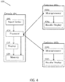
- FIG. 4 is a block diagram of electrical components of a catheter identification system 400.
- the catheter identification system 400 comprises a console 404 and two catheters: catheter 402a and catheter 402b.
- the catheter identification system may comprise more than two catheters.
- the console includes an input device 406, a processor 414, a display 416, and a memory 420.
- the input device 406, the display 416, and the memory 420 are coupled to the processor 414.
- the catheter 402a includes a microprocessor 426a and a handle display 428a.
- the catheter 402b similarly includes a microprocessor 426b and a handle display 428b.
- the processor 414 is coupled to the catheter 402a via microprocessor 426a; and is also coupled to the catheter 402b via microprocessor 426b.
- a configurable color is input in the input device 406 to uniquely identify catheter 402a.
- the input device 406 then communicates the configurable color input to the signal processor 414 in the console 404.
- the processor 414 may comprise a general-purpose computer, with suitable front end and interface circuits for receiving signals from the input device 406, the catheter 402a, and the catheter 402b.
- the processor 414 also controls the display 416 and the microprocessor 426a of the catheter 402a and the microprocessor 426b of the catheter 402b to depict the selected colors for catheter identification.
- the processor 414 Based on the signals received from the input device in the console 404 regarding the configurable color input, the processor 414 displays the color input on the display 416 in the console 404 by depicting an image of the catheter 402a having the selected color. Accordingly, as the operator manipulates the identified catheter on the display 416, the catheter 402a on the display 416 will reflect or depict that selected color. This may be manifested in a color outline, a solid color, a color indicator or the like.
- the processor 414 may then store the configurable color input data in the memory 420.
- the processor 414 may also communicate with the display 416 to store the displayed image in memory 420.
- the processor 414 also sends the configurable color input data to the microprocessor 426a on the catheter 402a.
- the microprocessor 426a then programs the handle display 428a on the catheter 402a to display the input color from the console.
- the color of the handle display 428a of the catheter 402a reflects the same color of the catheter 402a in the image on the display 416.
- a different configurable color may be input in the input device 406 of the console 404 in a similar manner for the catheter 402b.
- the input device 406 communicates the configurable color input to the signal processor 414.
- the processor 414 displays the color input on the display 416 in the console 404 containing an image of the catheter 402b.
- the selected color will be reflected as color outline, a solid color, a color indicator, or the like as the operator manipulates the catheter depicted on the display 416.
- the processor 414 may then store the configurable color input data in the memory 420 and may also communicate with the display 416 to store the image in memory 420.
- the processor 414 also sends the configurable color input data to the microprocessor 426b on the catheter 402b.
- the microprocessor 426b programs the handle display 428b on the catheter 402b to display the input color from the console.
- a configurable color input of blue to identify catheter 402a and a configurable color input of red for catheter 402b may be input in the input device 406.
- the configurable color input data is then sent to the processor 414, which communicates with the display 416 to depict catheter 426a as blue and catheter 426b as red on the display 416 in the console 404.
- the processor 414 then transmits the color input data to microprocessor 426a, which programs a handle display 428a to display a blue color for the catheter 402a.
- the processor 414 also transmits the color input data to microprocessor 426b, which programs the handle display 428b to display a red color for the catheter 402b.
- the catheter 402a and the catheter 402b are each uniquely identified by a different configurable color, and this color is reflected in the image of the catheters on the display 416.
- the configurable colors input for the catheter 402a and the catheter 402b and thus the colors depicted for catheter 402a and catheter 402b on the display 416 and the handle display 428a and the handle display 428b, may be changed at any time by selecting a color from a range of colors on the input device 406.
Landscapes
- Health & Medical Sciences (AREA)
- Life Sciences & Earth Sciences (AREA)
- Engineering & Computer Science (AREA)
- Surgery (AREA)
- Veterinary Medicine (AREA)
- Biomedical Technology (AREA)
- Heart & Thoracic Surgery (AREA)
- Animal Behavior & Ethology (AREA)
- General Health & Medical Sciences (AREA)
- Public Health (AREA)
- Molecular Biology (AREA)
- Medical Informatics (AREA)
- Pathology (AREA)
- Physics & Mathematics (AREA)
- Biophysics (AREA)
- Nuclear Medicine, Radiotherapy & Molecular Imaging (AREA)
- Cardiology (AREA)
- Oral & Maxillofacial Surgery (AREA)
- Hematology (AREA)
- Anesthesiology (AREA)
- Pulmonology (AREA)
- Plasma & Fusion (AREA)
- Otolaryngology (AREA)
- Human Computer Interaction (AREA)
- Physiology (AREA)
- Measuring And Recording Apparatus For Diagnosis (AREA)
- Surgical Instruments (AREA)
- Media Introduction/Drainage Providing Device (AREA)
- Apparatus For Radiation Diagnosis (AREA)
Abstract
Description
- In certain diagnostic and therapeutic techniques, including cardiac ablation, multiple catheters are inserted into chambers of the heart. During such procedures, a physician navigates the distal end of a catheter in a patient's body. The physician moves the distal end of the catheter by manipulating the proximal end of the catheter. One example of manipulating the proximal end includes using a handle fitted at the proximal end of the catheter.
- Current catheter-based medical systems possess the ability to visualize a map of the distal end of the catheters within the heart on a display. Visualization is provided for multiple purposes, including for catheter manipulation. Accordingly, as a catheter is physically moved within the heart, the movement is visualized on the display for the physician. When multiple catheters are inserted into the patient's body, the physician can differentiate the catheters visualized on the display by selecting a specific color for each catheter on the display. The catheter sheaths are then highlighted on the display in the selected color for visualization during the procedure.
- During medical procedures, the physician may be required to manipulate a single catheter while leaving the remaining inserted catheters in place. Current catheter-based medical systems, however, lack a proper identification system that is in sync with both the catheter handle and the display. The physician has no indication of which catheter handle corresponds to which catheter visualized on the display screen. Thus, in order to determine which catheter handle corresponds to a specific catheter on the display screen, the physician must physically move the catheter within the patient's body and simultaneously observe the visualization on the display to identify which catheter is moving. A system for visually identifying catheters for both catheter handles and display visualizations would therefore be useful to increase efficiency of medical procedures and prevent complications.
- A system and method for identifying a catheter inserted in a patient's body comprising a catheter comprising a handle, and a console comprising an input device, a display screen configured to depict an image of the catheter inside the patient's body, and a processor configured to communicate between the input device and the display screen and the catheter is provided. The system receives a configurable color input from the input device, depicts the configurable color on the image of the catheter on the display screen, and displays the configurable color on the handle of the corresponding catheter within the patient's body. This configuration may increase catheter identification efficiency during medical procedures and may also prevent catheter confusion and harm to the patient from incorrect catheter manipulation.
-
-
FIG. 1 is a schematic, pictorial illustration of a catheter identification system as it is used by a physician. -
FIG. 2 is a schematic representation of a catheter visualization image on a display of a catheter identification system. -
FIG. 3 is a pictorial illustration of a catheter handle as it relates to a catheter identification system. -
FIG. 4 is a block diagram of electrical components of a catheter identification system. - A system and method for catheter identification may be configured such that the color of a catheter depicted on a catheter visualization image on a display of a console reflects the color of an LED or electronic display on the catheter handle. This system may permit more efficient cardiac medical procedures by helping identify the catheter within a patient's body. In addition, a configurable color identification on both the image in the display of the console and the catheter handle may help decrease unnecessary movement of catheters by a physician to identify which catheter is the desired catheter to manipulate. Thus, this configuration may prevent catheter identification confusion and harm to the catheter or patient. This configuration may also allow other procedural data to be displayed on the catheter handle, including force and temperature information, the type of catheter being used, duration of ablation, and various alerts.
-
FIG. 1 is a schematic, pictorial illustration of a catheter identification system as it is used by a physician. Thecatheter identification system 100 may be based, for example, on the CARTO© systems, produced by Biosense Webster Inc. (Diamond Bar, Calif.). These systems may utilize electromagnetic technology to create real-time three-dimensional (3D) maps of a patient's cardiac structures. Thecatheter identification system 100 comprises invasive probes in the form of acatheter 102a and acatheter 102b, as well as acontrol console 104. Theconsole 104 includes adisplay 116, aprocessor 114, amemory 120, and one ormore input devices 122. In other embodiments, thesystem 100 may comprise additional catheters. - In the present embodiment, the
catheter 102a and thecatheter 102b may be used in mapping or ablating endocardial tissue. In other embodiments, thecatheters catheter identification system 100 may be used to perform other of therapeutic or diagnostic procedures. Catheters for mapping and/or ablation typically carry one or more magnetic position sensors for generating signals that are used to determine position coordinates of a distal portion of the catheter. Magnetic field generators are thus driven to generate magnetic fields in the vicinity of the patient. The field generators comprise coils, which are placed below the patient's torso at known positions external to the patient. The coils generate magnetic fields that are sensed by the magnetic position sensors carried in the catheter. Electrical signals are generated by the sensors and are then passed to a signal processor via leads that extend through the catheter. During a catheter ablation procedure, once the catheter reaches the heart, radiofrequency (RF) energy is delivered to specific areas of the heart wall to produce a small lesion, to block faulty electrical impulses that can cause heart rhythm disorders. The 3D map image that is generated by the system aids a physician in steering the catheter to areas in the heart where RF energy needs to be administered. - During ablation or other therapeutic or diagnostic procedures, a physician may insert several catheters into a patient's body. The insertion of multiple catheters makes it difficult to distinguish an individual catheter handle and the corresponding catheter within the patient's body for manipulating a specific catheter. Current catheter systems do not include an identification system for a desired catheter handle among multiple catheters inserted within a patient's body, and the corresponding desired catheter on the 3D map image. Instead, in order to differentiate a desired catheter handle to manipulate a desired catheter, the physician must move the catheter handle to observe the catheter movement on the generated 3D map image. By having a physician move other catheters in order to identify the desired catheter within the patient's body to manipulate, inefficiency of the procedure is increased and identification confusion resulting in harm to the catheter or patient is likely to occur.
- For example, a physician may select one of multiple catheters on a display depicting a 3D map image of the catheters in a patient's cardiac structures to be colored blue. The physician may select this color to differentiate the specific catheter on the image from the other catheters. The physician, however, has no way of identifying which catheter in the patient's body is the blue catheter displayed on the screen. The physician thus has to move each catheter within the patient's body until the blue catheter on the display is observed to move with respect to the catheter being moved by the physician. Unnecessary movement of the catheters within the patient's body to identify the desired catheter may decrease efficiency of the medical procedure, may damage the catheter, and may even be harmful to the patient.
- Returning to
FIG. 1 , in the present embodiment, anoperator 106, such as a physician, inserts thecatheter 102a and thecatheter 102b through the vascular system of apatient 110 so that adistal end 108a ofcatheter 102a and adistal end 108b ofcatheter 102b enter a chamber of the patient'sheart 112. The operator advances the catheters so that a tip of thedistal end 108a and a tip of thedistal end 108b engage endocardial tissue at desired locations. Thecatheter 102a is connected by asuitable cable 140a at its proximal end to theconsole 104. In addition, thecatheter 102b is connected by asuitable cable 140b at its proximal end to theconsole 104. Theconsole 104 uses a position sensing technique to determine position coordinates of thedistal end 108a of thecatheter 102a and thedistal end 108b of thecatheter 102b inside theheart 112. - The
console 104 uses any position sensing technique, including magnetic position sensing. Thesignal processor 114 processes the position sensing data in order to determine the position coordinates of thedistal end 108a and thedistal end 108b, including both location and orientation coordinates. Theprocessor 114 may comprise a general-purpose computer, with suitable front end and interface circuits for receiving signals from thecatheter 102a and thecatheter 102b and controlling the other components of theconsole 104. Theprocessor 114 may be programmed in software to carry out the functions described herein. The software may be downloaded to theconsole 104 in electronic form, over a network, for example, or it may be provided on tangible media, such as optical, magnetic or electronic memory media. In other embodiments, some or all of the functions of theprocessor 114 may be carried out by dedicated or programmable digital hardware components. - Based on the signals received from the
catheter 102a and thecatheter 102b, as well as from other components of thecatheter identification system 100, theprocessor 114 drives thedisplay 116 to give theoperator 106 visual feedback through animage 118. Theimage 118 depicts a 3D map of thedistal end 108a of thecatheter 102a and thedistal end 108b of thecatheter 102b in the patient's body, as well as status information and guidance regarding the procedure that is in progress. Theimage 118 provides accurate visualization of multiple catheters in the patient'sheart 112 and pinpoints the exact location and orientation of thecatheter 102a and thecatheter 102b. Theprocessor 114 may store data representing theimage 118 in thememory 120. - The
operator 106 may manipulate theimage 118 using theinput device 122 on theconsole 104. Theoperator 106 may thus use theinput device 122 to select configurable colors from a range of different colors to uniquely identify both thecatheter 102a and thecatheter 102b on theimage 118. The configurable color input data for thecatheter 102a and thecatheter 102b on theimage 118 is then communicated to theprocessor 114. Theprocessor 114 then communicates the color input to thecatheter 102a and thecatheter 102b to display the colors selected by theoperator 106 in theimage 118 on the body of the respective catheter. - For example, if the
operator 106 wishes thecatheter 102a to have a red sheath color and thecatheter 102b to have a blue sheath color on theimage 118, theoperator 106 selects the colors using theinput device 122 on theconsole 104 to input the colors into theidentification system 100. Thus, thecatheter 102a is depicted on theimage 118 with a red sheath color, while thecatheter 102b is depicted on theimage 118 with a blue sheath color. The configurable color input is then communicated to theprocessor 114. The processor then communicates both to thecatheter 102a inserted within the patient's body to display a red color on thecatheter 102a, and to thecatheter 102b inserted within the patient's body to display a blue color on thecatheter 102b. Thus, the colors depicted on the handle of thecatheter 102a and the handle of thecatheter 102b, respectively, reflect the colors of the catheter sheath of thecatheter 102a and the catheter sheath of thecatheter 102b on theimage 118, respectively. -
FIG. 2 is a schematic representation of a catheter visualization image on a display of a catheter identification system. Theimage 200 includes anicon 230a corresponding to the distal end 208a of thecatheter 102a, as depicted inFIG. 1 , and anicon 230b corresponding to the distal end 208b of thecatheter 102b, as depicted inFIG. 1 . In other embodiments, more than two icons corresponding to more than two catheters in the patient's body are depicted in theimage 200. - In the present embodiment, the
image 200 is illustrated on a display (not depicted), as an aid in visualizing the distal end of the catheters within the heart. The image includes a 3D graphical map of aninner surface 212 of the heart chamber in which the distal end of the catheters are located.Surface 212 may be fully reconstructed, as shown inFIG. 2 , or only partially reconstructed. The position of theicon 230a and theicon 230b relative to thesurface 212 gives an indication of the location of the actual distal ends of the catheters in the heart chamber. - At least a
portion 232a of theicon 230a and aportion 232b of theicon 230b may display a uniquely identifiable color (represented in the figure by hatching) on theimage 200, as input by an operator (not depicted). Accordingly, as the operator manipulates the catheter on the display, it will reflect or display that selected color. This may be manifested in a solid color, colored outline, a color indicator, or the like. For example, thecatheter 102a, as depicted inFIG. 1 , may be marked a green color on theimage 200 to distinguish thecatheter 102a on theimage 200. In the present embodiment, the portion of the icons displaying the uniquely identifiable color may reflect the sheath of each catheter. In other embodiments, the portion may reflect any other part of the catheter. - Current catheter systems, however, do not include an identification system for a catheter handle among multiple catheters inserted within a patient's body. A physician must instead move the catheter handle to observe the catheter movement on the generated 3D image. By having a physician move other catheters in order to identify the desired catheter within the patient's body to manipulate, inefficiency of the procedure is increased and harm to the catheter or patient is likely to occur. Returning to
FIG. 2 , the identification of a desiredcatheter 102a, as depicted inFIG. 1 , in both theimage 200 and thecatheter 102a inserted within the patient's body through a configurable color may allow for a more efficient catheter identification process, and may reduce identification confusion and catheter or patient harm. -
FIG. 3 is a pictorial illustration of a catheter handle as it relates to a catheter identification system. The catheter identification system 300 includes anexample catheter 302. Thecatheter 302 includes ahandle 324. Thehandle 324 includes amicroprocessor 326 and ahandle display 328. Themicroprocessor 326 controls thehandle display 328 and provides an identifiable state to thehandle display 328 including, but not limited to, color or graphical information to reflect the identification color input in theconsole 304. - Thus, when a configurable color is input in the
console 304 to identify thecatheter 302, the input color selection for thecatheter 302, i.e. the configurable color input, is communicated to theprocessor 314. In the present embodiment, theprocessor 314 is located in theconsole 304. Theprocessor 314 may comprise a general-purpose computer, with suitable front end and interface circuits for receiving signals from thecatheter 302 and theconsole 304, and for controlling both the color displayed on thecatheter 302 and other components of theconsole 304. Based on the input color selection for thecatheter 302 that is input into theconsole 304, theprocessor 314 communicates the configurable color input to themicroprocessor 326 on thehandle 324 of thecatheter 302. Themicroprocessor 326 communicates with thehandle display 328 by sending a signal to display the particular configurable color input in theconsole 304. - The
handle display 328 may comprise a light emitting diode (LED) or electronic display. In the present embodiment, thehandle display 328 includes a multicolored LED and textual display. The LED allows the system 300 to display a color, e.g. red, blue, etc., on thecatheter handle 324 in order to uniquely identify thecatheter 302. In other embodiments, thehandle display 328 may include a graphic display on thecatheter handle 324, or may include various combinations of the multicolored LED, textual, and graphic displays. The textual or graphic display may be used to communicate additional information including force or temperature parameters, type of catheter used, duration of ablation, and various alerts. -
FIG. 4 is a block diagram of electrical components of acatheter identification system 400. In the present embodiment, thecatheter identification system 400 comprises aconsole 404 and two catheters:catheter 402a andcatheter 402b. In other embodiments, the catheter identification system may comprise more than two catheters. The console includes aninput device 406, aprocessor 414, adisplay 416, and amemory 420. Theinput device 406, thedisplay 416, and thememory 420 are coupled to theprocessor 414. Thecatheter 402a includes amicroprocessor 426a and ahandle display 428a. Thecatheter 402b similarly includes amicroprocessor 426b and ahandle display 428b. Theprocessor 414 is coupled to thecatheter 402a viamicroprocessor 426a; and is also coupled to thecatheter 402b viamicroprocessor 426b. - In the present embodiment, a configurable color is input in the
input device 406 to uniquely identifycatheter 402a. Theinput device 406 then communicates the configurable color input to thesignal processor 414 in theconsole 404. Theprocessor 414 may comprise a general-purpose computer, with suitable front end and interface circuits for receiving signals from theinput device 406, thecatheter 402a, and thecatheter 402b. Theprocessor 414 also controls thedisplay 416 and themicroprocessor 426a of thecatheter 402a and themicroprocessor 426b of thecatheter 402b to depict the selected colors for catheter identification. - Based on the signals received from the input device in the
console 404 regarding the configurable color input, theprocessor 414 displays the color input on thedisplay 416 in theconsole 404 by depicting an image of thecatheter 402a having the selected color. Accordingly, as the operator manipulates the identified catheter on thedisplay 416, thecatheter 402a on thedisplay 416 will reflect or depict that selected color. This may be manifested in a color outline, a solid color, a color indicator or the like. Theprocessor 414 may then store the configurable color input data in thememory 420. Theprocessor 414 may also communicate with thedisplay 416 to store the displayed image inmemory 420. Theprocessor 414 also sends the configurable color input data to themicroprocessor 426a on thecatheter 402a. Themicroprocessor 426a then programs thehandle display 428a on thecatheter 402a to display the input color from the console. Thus, the color of thehandle display 428a of thecatheter 402a reflects the same color of thecatheter 402a in the image on thedisplay 416. - A different configurable color may be input in the
input device 406 of theconsole 404 in a similar manner for thecatheter 402b. Theinput device 406 communicates the configurable color input to thesignal processor 414. Theprocessor 414 then displays the color input on thedisplay 416 in theconsole 404 containing an image of thecatheter 402b. Thus, the selected color will be reflected as color outline, a solid color, a color indicator, or the like as the operator manipulates the catheter depicted on thedisplay 416. Theprocessor 414 may then store the configurable color input data in thememory 420 and may also communicate with thedisplay 416 to store the image inmemory 420. Theprocessor 414 also sends the configurable color input data to themicroprocessor 426b on thecatheter 402b. Themicroprocessor 426b programs thehandle display 428b on thecatheter 402b to display the input color from the console. - For example, a configurable color input of blue to identify
catheter 402a and a configurable color input of red forcatheter 402b may be input in theinput device 406. The configurable color input data is then sent to theprocessor 414, which communicates with thedisplay 416 to depictcatheter 426a as blue andcatheter 426b as red on thedisplay 416 in theconsole 404. Theprocessor 414 then transmits the color input data tomicroprocessor 426a, which programs ahandle display 428a to display a blue color for thecatheter 402a. Theprocessor 414 also transmits the color input data tomicroprocessor 426b, which programs thehandle display 428b to display a red color for thecatheter 402b. - As a result, the
catheter 402a and thecatheter 402b are each uniquely identified by a different configurable color, and this color is reflected in the image of the catheters on thedisplay 416. The configurable colors input for thecatheter 402a and thecatheter 402b, and thus the colors depicted forcatheter 402a andcatheter 402b on thedisplay 416 and thehandle display 428a and thehandle display 428b, may be changed at any time by selecting a color from a range of colors on theinput device 406. - It should thus be understood that many variations are possible based on the disclosure herein. Although features and elements are described above in particular combinations, each feature or element can be used alone without the other features and elements or in various combinations with or without other features and elements.
Claims (12)
- A system for identifying a catheter inserted in a patient's body, comprising:a catheter comprising:a handle,an invasive probe having a proximal end connected to the handle and a distal tip, anda magnetic position sensing assembly located within the invasive probe; anda console comprising:an input device,a display screen configured to depict an image of the catheter inside the patient's body, anda processor configured to communicate between the input device, the display screen, and the catheter;wherein the processor receives a configurable color input from the input device, depicts the configurable color on the image of the catheter on the display screen, and displays the configurable color on the handle of the corresponding catheter within the patient's body.
- The system of claim 1, wherein the processor is configured to use the magnetic position sensing assembly to sense the position of the distal tip relative to the distal end of the invasive probe and to display an icon on the display screen that represents the catheter.
- The system according to claim 1, wherein the handle further comprises:a microprocessor configured to receive the configurable color input, anda handle display configured to display the selected color.
- The system according to claim 3, wherein the handle display comprises:a light emitting diode configured to display a color out of a range of colors, anda textual display.
- The system according to claim 3, wherein the handle display further comprises a graphic display.
- The system according to claim 3, wherein the handle display is further configured to display information including force and temperature data, the type of catheter being used, ablation duration, and alerts.
- The system according to claim 1, wherein the console further comprises a memory configured to store the configurable color input and the image of the catheter on the display.
- A method for identifying a catheter inserted in a patient's body, comprising:inputting a configurable color for the catheter into an input device by selecting the configurable color from a range of colors,acquiring the configurable color input by a processor,displaying the configurable color on an image of the catheter on a display screen, anddisplaying the configurable color on a handle of the catheter.
- The method according to claim 8, wherein said displaying the configurable color on the handle further comprises:communicating the configurable color input to a microprocessor on the handle by the processor, anddisplaying the configurable color on a handle display by the microprocessor.
- The method according to claim 9, wherein said displaying the configurable color on a handle display by the microprocessor further comprises programming a light emitting diode on the handle display to display the selected color.
- The method according to claim 9, further comprising displaying information including force and temperature data, the type of catheter being used, ablation duration, and alerts on a textual display on the handle display.
- The method according to claim 8, further comprising storing the configurable color input and the image of the catheter on the display screen in a memory.
Applications Claiming Priority (1)
| Application Number | Priority Date | Filing Date | Title |
|---|---|---|---|
| US15/439,490 US20180235509A1 (en) | 2017-02-22 | 2017-02-22 | Catheter identification system and method |
Publications (2)
| Publication Number | Publication Date |
|---|---|
| EP3366248A1 true EP3366248A1 (en) | 2018-08-29 |
| EP3366248B1 EP3366248B1 (en) | 2019-05-15 |
Family
ID=61274023
Family Applications (1)
| Application Number | Title | Priority Date | Filing Date |
|---|---|---|---|
| EP18157893.1A Active EP3366248B1 (en) | 2017-02-22 | 2018-02-21 | Catheter identification system and method |
Country Status (8)
| Country | Link |
|---|---|
| US (1) | US20180235509A1 (en) |
| EP (1) | EP3366248B1 (en) |
| JP (1) | JP2018134412A (en) |
| CN (1) | CN108452424A (en) |
| AU (1) | AU2018200133A1 (en) |
| CA (1) | CA2994457A1 (en) |
| ES (1) | ES2733856T3 (en) |
| IL (1) | IL256923B (en) |
Families Citing this family (6)
| Publication number | Priority date | Publication date | Assignee | Title |
|---|---|---|---|---|
| CN112165914A (en) * | 2018-05-21 | 2021-01-01 | 美敦力公司 | Handheld pulse field ablation generator |
| JP2022526527A (en) * | 2019-03-26 | 2022-05-25 | コーニンクレッカ フィリップス エヌ ヴェ | Persistent guidewire identification |
| US12303187B2 (en) * | 2019-11-29 | 2025-05-20 | Canon Medical Systems Corporation | Medical image processing apparatus |
| CN111956936B (en) * | 2020-08-25 | 2023-06-09 | 深圳市赛禾医疗技术有限公司 | Pressure wave balloon catheter identification method and treatment device for angioplasty |
| US12336823B2 (en) * | 2021-12-06 | 2025-06-24 | Biosense Webster (Israel) Ltd. | Catheter connection configuration system |
| WO2026044205A1 (en) * | 2024-08-23 | 2026-02-26 | Medtronic Vascular, Inc. | System and method for detection of manipulated guidewire |
Citations (4)
| Publication number | Priority date | Publication date | Assignee | Title |
|---|---|---|---|---|
| US5489275A (en) * | 1994-11-14 | 1996-02-06 | Ep Technologies, Inc. | Identification ring for catheter |
| US20110218546A1 (en) * | 2008-10-22 | 2011-09-08 | Blue Ortho | Device for controlled adjustment of a surgical positioning unit |
| US20140005475A1 (en) * | 2012-06-27 | 2014-01-02 | National Chiao Tung University | Image Tracking System and Image Tracking Method Thereof |
| US20160242666A1 (en) * | 2015-02-19 | 2016-08-25 | Chandrashekhar Pujar | Method and Apparatus for Electrophysiology Catheter Scheme Configuration |
Family Cites Families (5)
| Publication number | Priority date | Publication date | Assignee | Title |
|---|---|---|---|---|
| WO2009048943A1 (en) * | 2007-10-09 | 2009-04-16 | Boston Scientific Scimed, Inc. | Cooled ablation catheter devices and methods of use |
| US9101735B2 (en) * | 2008-07-07 | 2015-08-11 | Intuitive Surgical Operations, Inc. | Catheter control systems |
| US20100030061A1 (en) * | 2008-07-31 | 2010-02-04 | Canfield Monte R | Navigation system for cardiac therapies using gating |
| US9326700B2 (en) * | 2008-12-23 | 2016-05-03 | Biosense Webster (Israel) Ltd. | Catheter display showing tip angle and pressure |
| US20130211221A1 (en) * | 2012-02-08 | 2013-08-15 | Imricor Medical Systems, Inc. | System and method for identifying and communicating with an interventional medical device |
-
2017
- 2017-02-22 US US15/439,490 patent/US20180235509A1/en not_active Abandoned
-
2018
- 2018-01-08 AU AU2018200133A patent/AU2018200133A1/en not_active Abandoned
- 2018-01-15 IL IL256923A patent/IL256923B/en active IP Right Grant
- 2018-02-08 CA CA2994457A patent/CA2994457A1/en not_active Abandoned
- 2018-02-21 EP EP18157893.1A patent/EP3366248B1/en active Active
- 2018-02-21 JP JP2018028567A patent/JP2018134412A/en not_active Abandoned
- 2018-02-21 ES ES18157893T patent/ES2733856T3/en active Active
- 2018-02-22 CN CN201810153943.6A patent/CN108452424A/en active Pending
Patent Citations (4)
| Publication number | Priority date | Publication date | Assignee | Title |
|---|---|---|---|---|
| US5489275A (en) * | 1994-11-14 | 1996-02-06 | Ep Technologies, Inc. | Identification ring for catheter |
| US20110218546A1 (en) * | 2008-10-22 | 2011-09-08 | Blue Ortho | Device for controlled adjustment of a surgical positioning unit |
| US20140005475A1 (en) * | 2012-06-27 | 2014-01-02 | National Chiao Tung University | Image Tracking System and Image Tracking Method Thereof |
| US20160242666A1 (en) * | 2015-02-19 | 2016-08-25 | Chandrashekhar Pujar | Method and Apparatus for Electrophysiology Catheter Scheme Configuration |
Also Published As
| Publication number | Publication date |
|---|---|
| US20180235509A1 (en) | 2018-08-23 |
| IL256923B (en) | 2021-02-28 |
| CA2994457A1 (en) | 2018-08-22 |
| IL256923A (en) | 2018-02-28 |
| CN108452424A (en) | 2018-08-28 |
| AU2018200133A1 (en) | 2018-09-06 |
| JP2018134412A (en) | 2018-08-30 |
| EP3366248B1 (en) | 2019-05-15 |
| ES2733856T3 (en) | 2019-12-03 |
Similar Documents
| Publication | Publication Date | Title |
|---|---|---|
| EP3366248B1 (en) | Catheter identification system and method | |
| JP7662221B2 (en) | Graphical User Interface for Defining Anatomical Boundaries - Patent application | |
| US12138083B2 (en) | Flattened organ display | |
| JP6008960B2 (en) | Needle length determination and calibration for insertion guidance systems | |
| JP7611899B2 (en) | SYSTEM AND METHOD FOR ULTRASOUND PROBE NEEDLE TRACKING STATUS INDICATOR - Patent application | |
| KR102420386B1 (en) | Graphical user interface for displaying guidance information in multiple modes during video-guided procedures | |
| EP2575610B1 (en) | Insertion guidance system for needles and medical components | |
| US20210345893A1 (en) | Indicator system | |
| EP2837328B1 (en) | Unmapped region visualization | |
| EP3918989B1 (en) | Systems and methods for guiding a medical instrument | |
| CN111317568B (en) | Chest imaging, distance measurement, surgery awareness, and notification systems and methods | |
| US9326700B2 (en) | Catheter display showing tip angle and pressure | |
| CN112472276A (en) | Graphical user interface for ablation system | |
| JP2020518326A (en) | Graphical user interface for monitoring image-guided procedures | |
| JP2016517299A (en) | System for detecting catheter electrode entry and exit from an introducer | |
| EP2742895A2 (en) | Recognizing which instrument is currently active | |
| EP3461446B1 (en) | Ablation size estimation and visual representation | |
| US20240099781A1 (en) | Neuromapping systems, methods, and devices |
Legal Events
| Date | Code | Title | Description |
|---|---|---|---|
| PUAI | Public reference made under article 153(3) epc to a published international application that has entered the european phase |
Free format text: ORIGINAL CODE: 0009012 |
|
| STAA | Information on the status of an ep patent application or granted ep patent |
Free format text: STATUS: THE APPLICATION HAS BEEN PUBLISHED |
|
| STAA | Information on the status of an ep patent application or granted ep patent |
Free format text: STATUS: REQUEST FOR EXAMINATION WAS MADE |
|
| AK | Designated contracting states |
Kind code of ref document: A1 Designated state(s): AL AT BE BG CH CY CZ DE DK EE ES FI FR GB GR HR HU IE IS IT LI LT LU LV MC MK MT NL NO PL PT RO RS SE SI SK SM TR |
|
| AX | Request for extension of the european patent |
Extension state: BA ME |
|
| 17P | Request for examination filed |
Effective date: 20180807 |
|
| RBV | Designated contracting states (corrected) |
Designated state(s): AL AT BE BG CH CY CZ DE DK EE ES FI FR GB GR HR HU IE IS IT LI LT LU LV MC MK MT NL NO PL PT RO RS SE SI SK SM TR |
|
| RIC1 | Information provided on ipc code assigned before grant |
Ipc: A61B 34/20 20160101ALN20180925BHEP Ipc: A61M 25/00 20060101ALI20180925BHEP Ipc: A61B 18/00 20060101ALN20180925BHEP Ipc: A61B 90/92 20160101ALI20180925BHEP Ipc: A61B 5/00 20060101ALI20180925BHEP Ipc: A61B 90/90 20160101ALI20180925BHEP Ipc: A61B 18/14 20060101AFI20180925BHEP |
|
| GRAP | Despatch of communication of intention to grant a patent |
Free format text: ORIGINAL CODE: EPIDOSNIGR1 |
|
| STAA | Information on the status of an ep patent application or granted ep patent |
Free format text: STATUS: GRANT OF PATENT IS INTENDED |
|
| INTG | Intention to grant announced |
Effective date: 20181113 |
|
| GRAJ | Information related to disapproval of communication of intention to grant by the applicant or resumption of examination proceedings by the epo deleted |
Free format text: ORIGINAL CODE: EPIDOSDIGR1 |
|
| STAA | Information on the status of an ep patent application or granted ep patent |
Free format text: STATUS: REQUEST FOR EXAMINATION WAS MADE |
|
| GRAJ | Information related to disapproval of communication of intention to grant by the applicant or resumption of examination proceedings by the epo deleted |
Free format text: ORIGINAL CODE: EPIDOSDIGR1 |
|
| STAA | Information on the status of an ep patent application or granted ep patent |
Free format text: STATUS: GRANT OF PATENT IS INTENDED |
|
| GRAP | Despatch of communication of intention to grant a patent |
Free format text: ORIGINAL CODE: EPIDOSNIGR1 |
|
| GRAS | Grant fee paid |
Free format text: ORIGINAL CODE: EPIDOSNIGR3 |
|
| INTC | Intention to grant announced (deleted) | ||
| RIC1 | Information provided on ipc code assigned before grant |
Ipc: A61B 18/14 20060101AFI20190225BHEP Ipc: A61B 34/20 20160101ALN20190225BHEP Ipc: A61M 25/00 20060101ALI20190225BHEP Ipc: A61B 90/92 20160101ALI20190225BHEP Ipc: A61B 5/00 20060101ALI20190225BHEP Ipc: A61B 18/00 20060101ALN20190225BHEP Ipc: A61B 90/90 20160101ALI20190225BHEP |
|
| INTG | Intention to grant announced |
Effective date: 20190314 |
|
| GRAA | (expected) grant |
Free format text: ORIGINAL CODE: 0009210 |
|
| STAA | Information on the status of an ep patent application or granted ep patent |
Free format text: STATUS: THE PATENT HAS BEEN GRANTED |
|
| AK | Designated contracting states |
Kind code of ref document: B1 Designated state(s): AL AT BE BG CH CY CZ DE DK EE ES FI FR GB GR HR HU IE IS IT LI LT LU LV MC MK MT NL NO PL PT RO RS SE SI SK SM TR |
|
| REG | Reference to a national code |
Ref country code: CH Ref legal event code: EP |
|
| REG | Reference to a national code |
Ref country code: DE Ref legal event code: R096 Ref document number: 602018000075 Country of ref document: DE |
|
| REG | Reference to a national code |
Ref country code: IE Ref legal event code: FG4D |
|
| REG | Reference to a national code |
Ref country code: NL Ref legal event code: FP |
|
| REG | Reference to a national code |
Ref country code: SE Ref legal event code: TRGR |
|
| REG | Reference to a national code |
Ref country code: LT Ref legal event code: MG4D |
|
| PG25 | Lapsed in a contracting state [announced via postgrant information from national office to epo] |
Ref country code: LT Free format text: LAPSE BECAUSE OF FAILURE TO SUBMIT A TRANSLATION OF THE DESCRIPTION OR TO PAY THE FEE WITHIN THE PRESCRIBED TIME-LIMIT Effective date: 20190515 Ref country code: AL Free format text: LAPSE BECAUSE OF FAILURE TO SUBMIT A TRANSLATION OF THE DESCRIPTION OR TO PAY THE FEE WITHIN THE PRESCRIBED TIME-LIMIT Effective date: 20190515 Ref country code: FI Free format text: LAPSE BECAUSE OF FAILURE TO SUBMIT A TRANSLATION OF THE DESCRIPTION OR TO PAY THE FEE WITHIN THE PRESCRIBED TIME-LIMIT Effective date: 20190515 Ref country code: NO Free format text: LAPSE BECAUSE OF FAILURE TO SUBMIT A TRANSLATION OF THE DESCRIPTION OR TO PAY THE FEE WITHIN THE PRESCRIBED TIME-LIMIT Effective date: 20190815 Ref country code: PT Free format text: LAPSE BECAUSE OF FAILURE TO SUBMIT A TRANSLATION OF THE DESCRIPTION OR TO PAY THE FEE WITHIN THE PRESCRIBED TIME-LIMIT Effective date: 20190915 Ref country code: HR Free format text: LAPSE BECAUSE OF FAILURE TO SUBMIT A TRANSLATION OF THE DESCRIPTION OR TO PAY THE FEE WITHIN THE PRESCRIBED TIME-LIMIT Effective date: 20190515 |
|
| PG25 | Lapsed in a contracting state [announced via postgrant information from national office to epo] |
Ref country code: BG Free format text: LAPSE BECAUSE OF FAILURE TO SUBMIT A TRANSLATION OF THE DESCRIPTION OR TO PAY THE FEE WITHIN THE PRESCRIBED TIME-LIMIT Effective date: 20190815 Ref country code: LV Free format text: LAPSE BECAUSE OF FAILURE TO SUBMIT A TRANSLATION OF THE DESCRIPTION OR TO PAY THE FEE WITHIN THE PRESCRIBED TIME-LIMIT Effective date: 20190515 Ref country code: RS Free format text: LAPSE BECAUSE OF FAILURE TO SUBMIT A TRANSLATION OF THE DESCRIPTION OR TO PAY THE FEE WITHIN THE PRESCRIBED TIME-LIMIT Effective date: 20190515 Ref country code: GR Free format text: LAPSE BECAUSE OF FAILURE TO SUBMIT A TRANSLATION OF THE DESCRIPTION OR TO PAY THE FEE WITHIN THE PRESCRIBED TIME-LIMIT Effective date: 20190816 |
|
| REG | Reference to a national code |
Ref country code: ES Ref legal event code: FG2A Ref document number: 2733856 Country of ref document: ES Kind code of ref document: T3 Effective date: 20191203 |
|
| REG | Reference to a national code |
Ref country code: AT Ref legal event code: MK05 Ref document number: 1132517 Country of ref document: AT Kind code of ref document: T Effective date: 20190515 |
|
| PG25 | Lapsed in a contracting state [announced via postgrant information from national office to epo] |
Ref country code: SK Free format text: LAPSE BECAUSE OF FAILURE TO SUBMIT A TRANSLATION OF THE DESCRIPTION OR TO PAY THE FEE WITHIN THE PRESCRIBED TIME-LIMIT Effective date: 20190515 Ref country code: AT Free format text: LAPSE BECAUSE OF FAILURE TO SUBMIT A TRANSLATION OF THE DESCRIPTION OR TO PAY THE FEE WITHIN THE PRESCRIBED TIME-LIMIT Effective date: 20190515 Ref country code: DK Free format text: LAPSE BECAUSE OF FAILURE TO SUBMIT A TRANSLATION OF THE DESCRIPTION OR TO PAY THE FEE WITHIN THE PRESCRIBED TIME-LIMIT Effective date: 20190515 Ref country code: EE Free format text: LAPSE BECAUSE OF FAILURE TO SUBMIT A TRANSLATION OF THE DESCRIPTION OR TO PAY THE FEE WITHIN THE PRESCRIBED TIME-LIMIT Effective date: 20190515 |
|
| REG | Reference to a national code |
Ref country code: DE Ref legal event code: R097 Ref document number: 602018000075 Country of ref document: DE |
|
| PG25 | Lapsed in a contracting state [announced via postgrant information from national office to epo] |
Ref country code: SM Free format text: LAPSE BECAUSE OF FAILURE TO SUBMIT A TRANSLATION OF THE DESCRIPTION OR TO PAY THE FEE WITHIN THE PRESCRIBED TIME-LIMIT Effective date: 20190515 |
|
| PLBE | No opposition filed within time limit |
Free format text: ORIGINAL CODE: 0009261 |
|
| STAA | Information on the status of an ep patent application or granted ep patent |
Free format text: STATUS: NO OPPOSITION FILED WITHIN TIME LIMIT |
|
| PG25 | Lapsed in a contracting state [announced via postgrant information from national office to epo] |
Ref country code: TR Free format text: LAPSE BECAUSE OF FAILURE TO SUBMIT A TRANSLATION OF THE DESCRIPTION OR TO PAY THE FEE WITHIN THE PRESCRIBED TIME-LIMIT Effective date: 20190515 |
|
| 26N | No opposition filed |
Effective date: 20200218 |
|
| PG25 | Lapsed in a contracting state [announced via postgrant information from national office to epo] |
Ref country code: PL Free format text: LAPSE BECAUSE OF FAILURE TO SUBMIT A TRANSLATION OF THE DESCRIPTION OR TO PAY THE FEE WITHIN THE PRESCRIBED TIME-LIMIT Effective date: 20190515 |
|
| REG | Reference to a national code |
Ref country code: SE Ref legal event code: EUG |
|
| REG | Reference to a national code |
Ref country code: BE Ref legal event code: MM Effective date: 20200229 |
|
| PG25 | Lapsed in a contracting state [announced via postgrant information from national office to epo] |
Ref country code: LU Free format text: LAPSE BECAUSE OF NON-PAYMENT OF DUE FEES Effective date: 20200221 Ref country code: CZ Free format text: LAPSE BECAUSE OF NON-PAYMENT OF DUE FEES Effective date: 20200221 Ref country code: MC Free format text: LAPSE BECAUSE OF FAILURE TO SUBMIT A TRANSLATION OF THE DESCRIPTION OR TO PAY THE FEE WITHIN THE PRESCRIBED TIME-LIMIT Effective date: 20190515 Ref country code: SE Free format text: LAPSE BECAUSE OF NON-PAYMENT OF DUE FEES Effective date: 20200222 |
|
| PG25 | Lapsed in a contracting state [announced via postgrant information from national office to epo] |
Ref country code: IE Free format text: LAPSE BECAUSE OF NON-PAYMENT OF DUE FEES Effective date: 20200221 |
|
| PG25 | Lapsed in a contracting state [announced via postgrant information from national office to epo] |
Ref country code: BE Free format text: LAPSE BECAUSE OF NON-PAYMENT OF DUE FEES Effective date: 20200229 |
|
| PGFP | Annual fee paid to national office [announced via postgrant information from national office to epo] |
Ref country code: FR Payment date: 20210112 Year of fee payment: 4 Ref country code: IT Payment date: 20210228 Year of fee payment: 4 Ref country code: NL Payment date: 20210212 Year of fee payment: 4 |
|
| PGFP | Annual fee paid to national office [announced via postgrant information from national office to epo] |
Ref country code: DE Payment date: 20210209 Year of fee payment: 4 |
|
| PG25 | Lapsed in a contracting state [announced via postgrant information from national office to epo] |
Ref country code: ES Free format text: LAPSE BECAUSE OF NON-PAYMENT OF DUE FEES Effective date: 20200222 |
|
| PG25 | Lapsed in a contracting state [announced via postgrant information from national office to epo] |
Ref country code: CH Free format text: LAPSE BECAUSE OF NON-PAYMENT OF DUE FEES Effective date: 20210228 Ref country code: LI Free format text: LAPSE BECAUSE OF NON-PAYMENT OF DUE FEES Effective date: 20210228 |
|
| PG25 | Lapsed in a contracting state [announced via postgrant information from national office to epo] |
Ref country code: MT Free format text: LAPSE BECAUSE OF FAILURE TO SUBMIT A TRANSLATION OF THE DESCRIPTION OR TO PAY THE FEE WITHIN THE PRESCRIBED TIME-LIMIT Effective date: 20190515 Ref country code: CY Free format text: LAPSE BECAUSE OF FAILURE TO SUBMIT A TRANSLATION OF THE DESCRIPTION OR TO PAY THE FEE WITHIN THE PRESCRIBED TIME-LIMIT Effective date: 20190515 |
|
| PG25 | Lapsed in a contracting state [announced via postgrant information from national office to epo] |
Ref country code: RO Free format text: LAPSE BECAUSE OF FAILURE TO SUBMIT A TRANSLATION OF THE DESCRIPTION OR TO PAY THE FEE WITHIN THE PRESCRIBED TIME-LIMIT Effective date: 20190515 Ref country code: MK Free format text: LAPSE BECAUSE OF FAILURE TO SUBMIT A TRANSLATION OF THE DESCRIPTION OR TO PAY THE FEE WITHIN THE PRESCRIBED TIME-LIMIT Effective date: 20190515 Ref country code: IS Free format text: LAPSE BECAUSE OF FAILURE TO SUBMIT A TRANSLATION OF THE DESCRIPTION OR TO PAY THE FEE WITHIN THE PRESCRIBED TIME-LIMIT Effective date: 20190915 |
|
| REG | Reference to a national code |
Ref country code: DE Ref legal event code: R119 Ref document number: 602018000075 Country of ref document: DE |
|
| REG | Reference to a national code |
Ref country code: NL Ref legal event code: MM Effective date: 20220301 |
|
| GBPC | Gb: european patent ceased through non-payment of renewal fee |
Effective date: 20220221 |
|
| PG25 | Lapsed in a contracting state [announced via postgrant information from national office to epo] |
Ref country code: NL Free format text: LAPSE BECAUSE OF NON-PAYMENT OF DUE FEES Effective date: 20220301 Ref country code: FR Free format text: LAPSE BECAUSE OF NON-PAYMENT OF DUE FEES Effective date: 20220228 |
|
| PG25 | Lapsed in a contracting state [announced via postgrant information from national office to epo] |
Ref country code: GB Free format text: LAPSE BECAUSE OF NON-PAYMENT OF DUE FEES Effective date: 20220221 Ref country code: DE Free format text: LAPSE BECAUSE OF NON-PAYMENT OF DUE FEES Effective date: 20220901 |
|
| PG25 | Lapsed in a contracting state [announced via postgrant information from national office to epo] |
Ref country code: IT Free format text: LAPSE BECAUSE OF NON-PAYMENT OF DUE FEES Effective date: 20220221 |
|
| PG25 | Lapsed in a contracting state [announced via postgrant information from national office to epo] |
Ref country code: SI Free format text: LAPSE BECAUSE OF FAILURE TO SUBMIT A TRANSLATION OF THE DESCRIPTION OR TO PAY THE FEE WITHIN THE PRESCRIBED TIME-LIMIT Effective date: 20190515 |