EP3366209A1 - Method for removing ghost artifact from magnetic resonance image and magnetic resonance device therefor - Google Patents
Method for removing ghost artifact from magnetic resonance image and magnetic resonance device therefor Download PDFInfo
- Publication number
- EP3366209A1 EP3366209A1 EP16857605.6A EP16857605A EP3366209A1 EP 3366209 A1 EP3366209 A1 EP 3366209A1 EP 16857605 A EP16857605 A EP 16857605A EP 3366209 A1 EP3366209 A1 EP 3366209A1
- Authority
- EP
- European Patent Office
- Prior art keywords
- scan line
- line image
- image
- reconstructed
- odd
- Prior art date
- Legal status (The legal status is an assumption and is not a legal conclusion. Google has not performed a legal analysis and makes no representation as to the accuracy of the status listed.)
- Granted
Links
Images






Classifications
-
- G—PHYSICS
- G01—MEASURING; TESTING
- G01R—MEASURING ELECTRIC VARIABLES; MEASURING MAGNETIC VARIABLES
- G01R33/00—Arrangements or instruments for measuring magnetic variables
- G01R33/20—Arrangements or instruments for measuring magnetic variables involving magnetic resonance
- G01R33/44—Arrangements or instruments for measuring magnetic variables involving magnetic resonance using nuclear magnetic resonance [NMR]
- G01R33/48—NMR imaging systems
- G01R33/54—Signal processing systems, e.g. using pulse sequences ; Generation or control of pulse sequences; Operator console
- G01R33/56—Image enhancement or correction, e.g. subtraction or averaging techniques, e.g. improvement of signal-to-noise ratio and resolution
- G01R33/5608—Data processing and visualization specially adapted for MR, e.g. for feature analysis and pattern recognition on the basis of measured MR data, segmentation of measured MR data, edge contour detection on the basis of measured MR data, for enhancing measured MR data in terms of signal-to-noise ratio by means of noise filtering or apodization, for enhancing measured MR data in terms of resolution by means for deblurring, windowing, zero filling, or generation of gray-scaled images, colour-coded images or images displaying vectors instead of pixels
-
- A—HUMAN NECESSITIES
- A61—MEDICAL OR VETERINARY SCIENCE; HYGIENE
- A61B—DIAGNOSIS; SURGERY; IDENTIFICATION
- A61B5/00—Measuring for diagnostic purposes; Identification of persons
- A61B5/05—Detecting, measuring or recording for diagnosis by means of electric currents or magnetic fields; Measuring using microwaves or radio waves
- A61B5/055—Detecting, measuring or recording for diagnosis by means of electric currents or magnetic fields; Measuring using microwaves or radio waves involving electronic [EMR] or nuclear [NMR] magnetic resonance, e.g. magnetic resonance imaging
-
- G—PHYSICS
- G01—MEASURING; TESTING
- G01R—MEASURING ELECTRIC VARIABLES; MEASURING MAGNETIC VARIABLES
- G01R33/00—Arrangements or instruments for measuring magnetic variables
- G01R33/20—Arrangements or instruments for measuring magnetic variables involving magnetic resonance
- G01R33/44—Arrangements or instruments for measuring magnetic variables involving magnetic resonance using nuclear magnetic resonance [NMR]
- G01R33/48—NMR imaging systems
- G01R33/4818—MR characterised by data acquisition along a specific k-space trajectory or by the temporal order of k-space coverage, e.g. centric or segmented coverage of k-space
-
- G—PHYSICS
- G01—MEASURING; TESTING
- G01R—MEASURING ELECTRIC VARIABLES; MEASURING MAGNETIC VARIABLES
- G01R33/00—Arrangements or instruments for measuring magnetic variables
- G01R33/20—Arrangements or instruments for measuring magnetic variables involving magnetic resonance
- G01R33/44—Arrangements or instruments for measuring magnetic variables involving magnetic resonance using nuclear magnetic resonance [NMR]
- G01R33/48—NMR imaging systems
- G01R33/54—Signal processing systems, e.g. using pulse sequences ; Generation or control of pulse sequences; Operator console
- G01R33/56—Image enhancement or correction, e.g. subtraction or averaging techniques, e.g. improvement of signal-to-noise ratio and resolution
- G01R33/5602—Image enhancement or correction, e.g. subtraction or averaging techniques, e.g. improvement of signal-to-noise ratio and resolution by filtering or weighting based on different relaxation times within the sample, e.g. T1 weighting using an inversion pulse
-
- G—PHYSICS
- G01—MEASURING; TESTING
- G01R—MEASURING ELECTRIC VARIABLES; MEASURING MAGNETIC VARIABLES
- G01R33/00—Arrangements or instruments for measuring magnetic variables
- G01R33/20—Arrangements or instruments for measuring magnetic variables involving magnetic resonance
- G01R33/44—Arrangements or instruments for measuring magnetic variables involving magnetic resonance using nuclear magnetic resonance [NMR]
- G01R33/48—NMR imaging systems
- G01R33/54—Signal processing systems, e.g. using pulse sequences ; Generation or control of pulse sequences; Operator console
- G01R33/56—Image enhancement or correction, e.g. subtraction or averaging techniques, e.g. improvement of signal-to-noise ratio and resolution
- G01R33/561—Image enhancement or correction, e.g. subtraction or averaging techniques, e.g. improvement of signal-to-noise ratio and resolution by reduction of the scanning time, i.e. fast acquiring systems, e.g. using echo-planar pulse sequences
- G01R33/5615—Echo train techniques involving acquiring plural, differently encoded, echo signals after one RF excitation, e.g. using gradient refocusing in echo planar imaging [EPI], RF refocusing in rapid acquisition with relaxation enhancement [RARE] or using both RF and gradient refocusing in gradient and spin echo imaging [GRASE]
- G01R33/5616—Echo train techniques involving acquiring plural, differently encoded, echo signals after one RF excitation, e.g. using gradient refocusing in echo planar imaging [EPI], RF refocusing in rapid acquisition with relaxation enhancement [RARE] or using both RF and gradient refocusing in gradient and spin echo imaging [GRASE] using gradient refocusing, e.g. EPI
-
- G—PHYSICS
- G01—MEASURING; TESTING
- G01R—MEASURING ELECTRIC VARIABLES; MEASURING MAGNETIC VARIABLES
- G01R33/00—Arrangements or instruments for measuring magnetic variables
- G01R33/20—Arrangements or instruments for measuring magnetic variables involving magnetic resonance
- G01R33/44—Arrangements or instruments for measuring magnetic variables involving magnetic resonance using nuclear magnetic resonance [NMR]
- G01R33/48—NMR imaging systems
- G01R33/54—Signal processing systems, e.g. using pulse sequences ; Generation or control of pulse sequences; Operator console
- G01R33/56—Image enhancement or correction, e.g. subtraction or averaging techniques, e.g. improvement of signal-to-noise ratio and resolution
- G01R33/565—Correction of image distortions, e.g. due to magnetic field inhomogeneities
- G01R33/56554—Correction of image distortions, e.g. due to magnetic field inhomogeneities caused by acquiring plural, differently encoded echo signals after one RF excitation, e.g. correction for readout gradients of alternating polarity in EPI
-
- G—PHYSICS
- G01—MEASURING; TESTING
- G01R—MEASURING ELECTRIC VARIABLES; MEASURING MAGNETIC VARIABLES
- G01R33/00—Arrangements or instruments for measuring magnetic variables
- G01R33/20—Arrangements or instruments for measuring magnetic variables involving magnetic resonance
- G01R33/44—Arrangements or instruments for measuring magnetic variables involving magnetic resonance using nuclear magnetic resonance [NMR]
- G01R33/48—NMR imaging systems
- G01R33/54—Signal processing systems, e.g. using pulse sequences ; Generation or control of pulse sequences; Operator console
- G01R33/56—Image enhancement or correction, e.g. subtraction or averaging techniques, e.g. improvement of signal-to-noise ratio and resolution
- G01R33/561—Image enhancement or correction, e.g. subtraction or averaging techniques, e.g. improvement of signal-to-noise ratio and resolution by reduction of the scanning time, i.e. fast acquiring systems, e.g. using echo-planar pulse sequences
- G01R33/5611—Parallel magnetic resonance imaging, e.g. sensitivity encoding [SENSE], simultaneous acquisition of spatial harmonics [SMASH], unaliasing by Fourier encoding of the overlaps using the temporal dimension [UNFOLD], k-t-broad-use linear acquisition speed-up technique [k-t-BLAST], k-t-SENSE
Definitions
- Embodiments relate to a method of removing ghost artifacts from echo planar imaging (EPI) data acquired by a magnetic resonance imaging (MRI) apparatus using EPI technology.
- EPI echo planar imaging
- MRI magnetic resonance imaging
- Magnetic resonance imaging is a technology that images an inside of a human body based on signals collected by resonating elements arranged in a predetermined magnetic field using radio frequency (RF) pulses.
- RF radio frequency
- magnetic resonance images may be acquired at a super high speed using echo planar imaging (EPI) technology.
- EPI technology may receive a magnetic resonance image in a single free induction decay (FID) signal for 40 to 100 milliseconds (ms), thereby implementing super high-speed imaging technology.
- FID free induction decay
- ms milliseconds
- Fast scanning of EPI may reduce issues relating to MRI or defects resulting from a movement of a target.
- EPI technology may generate a large field gradient magnetic field and perform switching at a rate of about 1 kilohertz (kHz), and thus it may be difficult to implement images using hardware and serious image distortion may occur due to magnetic susceptibility of the target.
- EPI technology reads data from an even scan line and an odd scan line in a k-space in different directions, and thus a phase difference may occur between the lines.
- the phase difference causes ghost artifacts in an image domain, and the ghost artifacts obstruct an appropriate analysis of EPI images.
- a reference scan may be acquired before a reconstructed image is acquired, and a phase difference between an even scan line and an odd scan line in a k-space may be calculated to correct a phase difference in a target image.
- only three scan lines are acquired from the additional image for correction to overcome the disadvantage in time.
- ghost artifacts still may not be removed suitably due to coil sensitivity in an MRI apparatus
- an additional image to offset ghost artifacts may be acquired by correcting a sequence to be used to acquire an EPI image. However, it also takes time since another additional image needs to be acquired further.
- An aspect provides a technology to remove ghost artifacts from an echo planar imaging (EPI) image acquired by a magnetic resonance imaging (MRI) apparatus without acquiring a reference scan when reconstructing a magnetic resonance image.
- EPI echo planar imaging
- MRI magnetic resonance imaging
- a method of reconstructing a magnetic resonance image including receiving echo planar imaging (EPI) data, acquiring an even scan line image and an odd scan line image from k-space data of the EPI data, and reconstructing missing portions of the even scan line image and the odd scan line image.
- EPI echo planar imaging
- the reconstructing of the missing portions of the even scan line image and the odd scan line image may include reconstructing the missing portions by constructing block Hankel matrices from the even scan line image and the odd scan line image based on a presence of an annihilation filter in a k-space and interpolating Fourier data yet to be measured through a low rank matrix completion algorithm.
- the reconstructing of the missing portions by constructing the block Hankel matrices from the even scan line image and the odd scan line image may include transforming the even scan line image and the odd scan line image into the block Hankel matrices using a commutative rule of a convolution operation of the k-space and the annihilation filter in a frequency domain.
- the method may further include generating a single reconstructed image by combining the reconstructed even scan line image and the reconstructed odd scan line image.
- the generating of the single reconstructed image may include generating the single reconstructed image using a sum of squares of the reconstructed even scan line image and the reconstructed odd scan line image.
- the reconstructing of the missing portions of the even scan line image and the odd scan line image may include reconstructing the even scan line image and the odd scan line image using a plurality of minimum rank matrix completion algorithms after changing pyramid patches, each having a pyramidal structure, into block Hankel matrices.
- the reconstructing of the images using the pyramid patches may include reconstructing the even scan line image and the odd scan line image through the matrix completion algorithms, reducing sizes of the pyramid patches, and reconstructing a low-frequency domain of a k-space through the matrix completion algorithms using values of the reconstructed even scan line image and the reconstructed odd scan line image as initial values.
- the reconstructing of the images using the pyramid patches may include applying a stop reference less than or equal to a preset reference to a pyramid patch including noise greater than or equal to the preset reference, and applying a stop reference greater than or equal to the preset reference to a pyramid patch from which a low-frequency domain is cut off, among the pyramid patches, each having the pyramidal structure.
- the EPI data may include at least one of single-coil EPI data or multi-coil EPI data.
- the reconstructing of the missing portions of the even scan line image and the odd scan line image may include reconstructing the missing portions by assigning a weighting to a k-space of each of the even scan line image and the odd scan line image and constructing block Hankel matrices from the weighted even scan line image and the weighted odd scan line image.
- an apparatus for reconstructing a magnetic resonance image including a processor configured to acquire an even scan line image and an odd scan line image from k-space data of EPI data, and reconstruct missing portions of the even scan line image and the odd scan line image.
- the processor may be configured to reconstruct the missing portions by constructing block Hankel matrices from the even scan line image and the odd scan line image based on a presence of an annihilation filter in a k-space and interpolating Fourier data yet to be measured through a low rank matrix completion algorithm.
- the processor may be configured to transform the even scan line image and the odd scan line image into the block Hankel matrices using a commutative rule of a convolution operation of the k-space and the annihilation filter in a frequency domain.
- the processor may be configured to generate a single reconstructed image by combining the reconstructed even scan line image and the reconstructed odd scan line image.
- the processor may be configured to generate the single reconstructed image using a sum of squares of the reconstructed even scan line image and the reconstructed odd scan line image.
- the processor may be configured to reconstruct the even scan line image and the odd scan line image using a plurality of minimum rank matrix completion algorithms after changing pyramid patches, each having a pyramidal structure, into block Hankel matrices.
- the processor may be configured to reconstruct the even scan line image and the odd scan line image through the matrix completion algorithms, reduce sizes of the pyramid patches, and reconstruct a low-frequency domain of a k-space through the matrix completion algorithms using values of the reconstructed even scan line image and the reconstructed odd scan line image as initial values.
- the processor may be configured to apply a stop reference less than or equal to a preset reference to a pyramid patch including noise greater than or equal to the preset reference, and apply a stop reference greater than or equal to the preset reference to a pyramid patch from which a low-frequency domain is cut off, among the pyramid patches, each having the pyramidal structure.
- the processor may be configured to reconstruct the missing portions by assigning a weighting to a k-space of each of the even scan line image and the odd scan line image and constructing block Hankel matrices from the weighted even scan line image and the weighted odd scan line image.
- ghost artifacts may be removed from a magnetic resonance image without acquiring a reference scan from an echo planar imaging (EPI) image.
- EPI echo planar imaging
- ghost artifacts may be removed only based on single-coil data, without using multi-coil data.
- ghost artifacts may be removed effectively, whereby more precise results of functional magnetic resonance imaging (fMRI) analysis may be obtained.
- fMRI functional magnetic resonance imaging
- FIG. 1 is a block diagram illustrating an apparatus for reconstructing a magnetic resonance image according to an embodiment.
- an apparatus 100 for reconstructing a magnetic resonance image may include a communicator 110, a processor 120, and a storage 130.
- the apparatus 100 may correct ghost artifacts in an echo planar imaging (EPI) image. Removal of the ghost artifacts may transform k-space data, separated into an even scan line image and an odd scan line image, into rank deficiency by constructing block Hankel matrices of the even scan line image and the odd scan line image based on a presence of an annihilation filter in a k-space. In this example, the apparatus 100 may solve the rank deficiency through various low rank matrix completion algorithms.
- EPI echo planar imaging
- the communicator 110 may receive EPI data from a magnetic resonance imaging (MRI) scanner (not shown).
- the communicator may receive the EPI data from the MRI scanner in a wireless or wired manner.
- MRI magnetic resonance imaging
- the EPI data may include at least one of single-coil EPI data or multi-coil EPI data.
- the communicator 110 may output a reconstructed magnetic resonance image to an output device so that a user may view the magnetic resonance image.
- the processor 120 may acquire an even scan line image and an odd scan line image from the k-space data of the received EPI data.
- the processor 120 may reconstruct missing portions of the even scan line image and the odd scan line image.
- the processor 120 may reconstruct the missing portions by interpolating Fourier data yet to be measured since the k-space data is transformed into the rank deficiency by constructing respective block Hankel matrices of the even scan line image and the odd scan line image based on the presence of the annihilation filter in the k-space.
- the processor 120 may solve the rank deficiency through a plurality of low rank matrix completion algorithms.
- the processor 120 may transform the even scan line image and the odd scan line image into the respective block Hankel matrices using a commutative rule of a convolution operation of the k-space and the annihilation filter in a frequency domain.
- the processor 120 may generate a single reconstructed image by combining the reconstructed even scan line image and the reconstructed odd scan line image.
- the processor 120 may generate the single reconstructed image using a sum of squares of the reconstructed even scan line image and the reconstructed odd scan line image.
- the processor 120 may reconstruct the even scan line image and the odd scan line image using a plurality of minimum rank matrix completion algorithms after changing pyramid patches, each having a pyramidal structure, into block Hankel matrices.
- the processor 120 may reconstruct the even scan line image and the odd scan line image through the matrix completion algorithms, reduce sizes of the pyramid patches, and reconstruct a low-frequency domain of the k-space through the matrix completion algorithms using values of the reconstructed even scan line image and the reconstructed odd scan line image as initial values.
- the processor 120 may apply a stop reference less than or equal to a preset reference to a pyramid patch including noise greater than or equal to the preset reference, and apply a stop reference greater than or equal to the preset reference to a pyramid patch from which a low-frequency domain is cut off, among the pyramid patches, each having the pyramidal structure.
- the processor 120 may reconstruct the missing portions by assigning a weighting to a k-space of each of the even scan line image and the odd scan line image and constructing block Hankel matrices from the weighted even scan line image and the weighted odd scan line image.
- the weighting may be determined based on a characteristic of sparsifying transform of an EPI image.
- the processor 120 may sparsely transform an EPI image by assigning the weighting to the k-space data before the block Hankel matrices are constructed.
- the storage 130 may arbitrarily store the EPI image received at the communicator 110, and also store the image reconstructed by the processor 120.
- FIG. 2 is a flowchart illustrating a method of reconstructing a magnetic resonance image according to an embodiment.
- an apparatus for reconstructing a magnetic resonance image may receive an EPI image.
- the apparatus for reconstructing a magnetic resonance image may separate an even scan line image and an odd scan line image from a k-space of the received EPI image.
- the apparatus for reconstructing a magnetic resonance image may reconstruct missing portions of the even scan line image and the odd scan line image.
- the apparatus for reconstructing a magnetic resonance image may transform k-space data, separated into an even scan line image and an odd scan line image, into rank deficiency by constructing block Hankel matrices of the even scan line image and the odd scan line image based on a presence of an annihilation filter in a k-space.
- the rank deficiency may be solved through a plurality of low rank matrix completion algorithms.
- the apparatus for reconstructing a magnetic resonance image may reconstruct the missing portions by interpolating Fourier data yet to be measured through the low rank matrix completion algorithms since the k-space data is transformed into the rank deficiency by constructing respective block Hankel matrices of the even scan line image and the odd scan line image based on the presence of the annihilation filter in the k-space.
- the apparatus for reconstructing a magnetic resonance image may transform the even scan line image and the odd scan line image into the block Hankel matrices using a commutative rule of a convolution operation of the k-space and the annihilation filter in a frequency domain.
- the apparatus for reconstructing a magnetic resonance image may reconstruct the missing portions by assigning a weighting to a k-space of each of the even scan line image and the odd scan line image and constructing block Hankel matrices from the weighted even scan line image and the weighted odd scan line image.
- the weighting may be determined based on a characteristic of sparsifying transform of an EPI image.
- the apparatus for reconstructing a magnetic resonance image may sparsely transform the EPI image before the block Hankel matrices are constructed.
- the apparatus for reconstructing a magnetic resonance image may reconstruct the even scan line image and the odd scan line image using a plurality of minimum rank matrix completion algorithms after changing pyramid patches, each having a pyramidal structure, into block Hankel matrices.
- the apparatus for reconstructing a magnetic resonance image may reconstruct the even scan line image and the odd scan line image through the matrix completion algorithms, reduce sizes of the pyramid patches, and reconstruct a low-frequency domain of the k-space through the matrix completion algorithms using values of the reconstructed even scan line image and the reconstructed odd scan line image as initial values.
- the apparatus for reconstructing a magnetic resonance image may generate a single reconstructed image by combining the reconstructed even scan line image and the reconstructed odd scan line image.
- the apparatus for reconstructing a magnetic resonance image may generate the single reconstructed image using a sum of squares of the reconstructed even scan line image and the reconstructed odd scan line image.
- FIG. 3 illustrates a method of reconstructing a magnetic resonance image using a k-space according to an embodiment.
- an apparatus for reconstructing a magnetic resonance image may separate an even scan line image 321, 322 and an odd scan line image 331, 332 from a k-space 312 of an EPI image 311.
- the apparatus for reconstructing a magnetic resonance image may acquire a reconstructed even scan line image 341, 342 by reconstructing the even scan line image 321, 322, and acquire a reconstructed odd scan line image 351, 352 by reconstructing the odd scan line image 331, 332.
- the apparatus for reconstructing a magnetic resonance image may acquire a final image 360 from which ghost artifacts are removed, by combining the reconstructed even scan line image 341, 342 and the reconstructed odd scan line image 351, 352.
- the EPI image may be expressed using Equation 1.
- S n k x , k y ⁇ m x , y e j 2 ⁇ ⁇ f x , y T E + n ⁇ N 2 E
- S P + ⁇ 1 n k x ⁇ G x + k x x + k y y d x d y
- Equation 1 m denotes an intensity of the image, and ⁇ f denotes a freuqency offset resulting from field inhomogeneity.
- x and y denote a direction of read-out and a direction of phase encoding, respectively.
- TE denotes an echo time
- ESP denotes a time interval between echoes.
- N denotes a total number of echoes, and n denotes an index of each echo line.
- a model of Equation 1 includes ghost artifacts resulting from a phase difference between echo lines.
- a value of (-1) n may vary based on whether n is an even number or an odd number.
- an even scan line and an odd scan line may have different polarities, which may be represented using virtual k-spaces, as expressed by Equation 2.
- Equation 2 S n ,+ ( k x , k y ) denotes a k-space in which even scane lines are collected, and S n ,- ( k x ,k y ) denotes a k-space in which odd scan lines are collected.
- the two separate k-spaces include missing odd scan lines and missing even scan lines, respectively, and thus may be regarded as being downsampled by a factor of 2. Accordingly, the method of reconstructing a magnetic resonance image may change into an issue of filling in the missing portions of the k-spaces.
- Equation 2 One equation in Equation 2 may be subtracted from the other equation, as expressed by Equation 3.
- Equation 3 may be approximated as expressed by Equation 4.
- S n , ⁇ k x , k y ⁇ ⁇ j 2 ⁇ k x ⁇ 2 ⁇ G x A x , y ⁇ f x , y e j 2 ⁇ k x x + k y y d x d y 2 ⁇ G x F ⁇ A x , y ⁇ f x , y ⁇ x
- Equation 4 may be the same as a result of performing Fourier transform on a gradient of a product of an RF offset and an image. Since A(x,y) ⁇ f(x,y) has a smooth gradient and S n, ⁇ ( k x , k y ) and has a sparse density, a difference S n , ⁇ between the k-space using the odd lines and the k-space using the even lines may be sparse. A Hankel matrix constructed based on S n, ⁇ ( k x , k y ) may be ranked low. Accordingly, an annihilation filter that satisfies Equation 5 may be present.
- Equation 5 H S n , ⁇ denotes a Hankel matrix constructed from S n, ⁇ , and denotes a vectorized form of a two-dimensional (2D) annihilation filter.
- S n , ⁇ S n ,- - S n ,+ is satisfied and thus, a relationship as expressed by Equation 6 may be obtained.
- a matrix may be generated by constructing respective block Hankel matrices from the k-space including the even scan lines and the k-space including the odd scan lines and combining the two matrices.
- a low rankness of the matrix Y may be used to fill in the missing portions of the data.
- a final image without ghost artifacts may be generated by combining the reconstructed even scan line image and the reconstructed odd scan line image.
- the reconstructed even scan line image and the odd scan line image may be combined using a sum of squares.
- restoration may be performed similarly by constructing a Hankel matrix, as expressed by Equation 6.
- Equation 7 ( i ) denotes a Hankel matrix at an i-th coil.
- FIG. 4 illustrates a method of constructing block Hankel matrices from a k-space in which data is insufficient according to an embodiment.
- patches 411, 412, 413, 414, and 415 may be extracted from a k-space 410 of an EPI image.
- each patch includes filled odd scan lines and missing even scan lines.
- an apparatus for reconstructing a magnetic resonance image may construct a Hankel matrix or Hankel matrices for each patch.
- the apparatus for reconstructing a magnetic resonance image may construct a Hankel matrix 421 for the patch 411, Hankel matrices 422 and 424 for the patch 412, Hankel matrices 423, 425, and 427 for the patch 413, Hankel matrices 426 and 428 for the patch 414, and a Hankel matrix 429 for the patch 415.
- Rank deficiency of the Hankel matrices may be used to reconstruct data of the missing portions.
- FIG. 5 illustrates a result of constructing a block Hankel matrix from each of an even scan line image and an odd scan line image according to an embodiment.
- a Hankel matrix 521 may be constructed from EPI data 511, and a Hankel matrix 522 may be constructed from EPI data 512.
- An apparatus for reconstructing a magnetic resonance image may fill in and reconstruct missing portions in each of the Hankel matrices 521 and 522, and generate a final image without ghost artifacts through a sum of squares.
- FIG. 6 illustrates a change in size of a reconstructed patch at each level of a pyramidal structure according to an embodiment.
- a low rank completion algorithm may be calculated efficiently through a pyramid-structured scheme.
- the low rank completion algorithm may be calculated with respect to an independent patch.
- a size of a patch may be reduced for each operation, and reconstruction may be performed differently based on a signal-to-noise ratio (SNR) for each operation, whereby a number of interactions of an iterative reconstruction-based low rank matrix completion algorithm may be reduced.
- SNR signal-to-noise ratio
- Such a pyramidal structure may apply to a kx-ky domain.
- a patch 610 in a first operation and a patch 620 in a second operation are illustrated.
- an x-axial length of a patch may be reduced to half a length of a patch in a previous operation. Since a center 611 of each patch includes a low-frequency portion at all times, reconstruction may be performed more precisely without noise as advancing to a subsequent operation. Thus, a number of iterations of a low rank matrix completion algorithm may decrease, and reconstructed data of a previous operation may be used as an initial value of each operation, whereby more accurate result values may be obtained.
- a length and a width of a patch may be reduced to those of a patch in a previous operation.
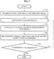
- FIG. 7 is a flowchart illustrating a reconstruction process to which a pyramidal structure is applied according to an embodiment.
- an apparatus for reconstructing a magnetic resonance image may separate an even scan line image and an odd scan line image from a k-space of an EPI image.
- the apparatus for reconstructing a magnetic resonance image may determine a pyramid patch.
- the apparatus for reconstructing a magnetic resonance image may reconstruct the even scan line image and the odd scan line image through a matrix completion algorithm, and reduce a size of the pyramid patch.
- the apparatus for reconstructing a magnetic resonance image may construct Hankel matrices of the k-space from the even scan line image and the odd scan line image.
- the apparatus for reconstructing a magnetic resonance image may reconstruct an image through a low rank matrix completion algorithm.
- the apparatus for reconstructing a magnetic resonance image may reconstruct a low-frequency domain of the k-space through the matrix completion algorithm using values of the restored even scan line image and the restored odd scan line image as initial values.
- the apparatus for reconstructing a magnetic resonance image may determine whether a pyramid level reaches a desired level.
- operations 720 through 740 may be iteratively performed until the pyramid level reaches the desired level while reducing a size of a patch to half a size of a previous patch that is yet to undergo operation 750.
- reconstruction may be performed differently based on an SNR for each level and for each operation, whereby a number of interactions of an iterative reconstruction-based low rank matrix completion algorithm may be reduced.
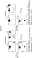
- FIGS. 8A and 8B illustrate results of a method of reconstructing a magnetic resonance image according to an embodiment.
- magnetic resonance images viewed from a side 811, a front 812, and a top 813 according to a conventional or related art include ghost artifacts, whereas magnetic resonance images viewed from a side 821, a front 822, and a top 823 according to an embodiment do not include ghost artifacts.
- a magnetic resonance image 831 according to a conventional or related art includes ghost artifacts (pointed by an arrow), whereas magnetic resonance images according to an embodiment, in detail, both a single-coil image 832 and a multi-coil image 833, do not include ghost artifacts.
- the units and/or modules described herein may be implemented using hardware components and software components.
- the hardware components may include microphones, amplifiers, band-pass filters, audio to digital convertors, and processing devices.
- a processing device may be implemented using one or more hardware device configured to carry out and/or execute program code by performing arithmetical, logical, and input/output operations.
- the processing device(s) may include a processor, a controller and an arithmetic logic unit, a digital signal processor, a microcomputer, a field programmable array, a programmable logic unit, a microprocessor or any other device capable of responding to and executing instructions in a defined manner.
- the processing device may run an operating system (OS) and one or more software applications that run on the OS.
- OS operating system
- the processing device also may access, store, manipulate, process, and create data in response to execution of the software.
- a processing device may include multiple processing elements and multiple types of processing elements.
- a processing device may include multiple processors or a processor and a controller.
- different processing configurations are possible, such as parallel processors.
- the software may include a computer program, a piece of code, an instruction, or some combination thereof, to independently or collectively instruct and/or configure the processing device to operate as desired, thereby transforming the processing device into a special purpose processor.
- Software and data may be embodied permanently or temporarily in any type of machine, component, physical or virtual equipment, computer storage medium or device, or in a propagated signal wave capable of providing instructions or data to or being interpreted by the processing device.
- the software also may be distributed over network coupled computer systems so that the software is stored and executed in a distributed fashion.
- the software and data may be stored by one or more non-transitory computer readable recording mediums.
- the methods according to the above-described embodiments may be recorded in non-transitory computer-readable media including program instructions to implement various operations of the above-described embodiments.
- the media may also include, alone or in combination with the program instructions, data files, data structures, and the like.
- the program instructions recorded on the media may be those specially designed and constructed for the purposes of embodiments, or they may be of the kind well-known and available to those having skill in the computer software arts.
- non-transitory computer-readable media examples include magnetic media such as hard disks, floppy disks, and magnetic tape; optical media such as CD-ROM discs, DVDs, and/or Blue-ray discs; magneto-optical media such as optical discs; and hardware devices that are specially configured to store and perform program instructions, such as read-only memory (ROM), random access memory (RAM), flash memory (e.g., USB flash drives, memory cards, memory sticks, etc.), and the like.
- program instructions include both machine code, such as produced by a compiler, and files containing higher level code that may be executed by the computer using an interpreter.
- the above-described devices may be configured to act as one or more software modules in order to perform the operations of the above-described embodiments, or vice versa.
Landscapes
- Physics & Mathematics (AREA)
- Health & Medical Sciences (AREA)
- Nuclear Medicine, Radiotherapy & Molecular Imaging (AREA)
- Engineering & Computer Science (AREA)
- High Energy & Nuclear Physics (AREA)
- General Health & Medical Sciences (AREA)
- Radiology & Medical Imaging (AREA)
- Condensed Matter Physics & Semiconductors (AREA)
- General Physics & Mathematics (AREA)
- Signal Processing (AREA)
- Life Sciences & Earth Sciences (AREA)
- Medical Informatics (AREA)
- Public Health (AREA)
- Biophysics (AREA)
- Pathology (AREA)
- Biomedical Technology (AREA)
- Heart & Thoracic Surgery (AREA)
- Veterinary Medicine (AREA)
- Surgery (AREA)
- Molecular Biology (AREA)
- Animal Behavior & Ethology (AREA)
- Computer Vision & Pattern Recognition (AREA)
- Artificial Intelligence (AREA)
- Magnetic Resonance Imaging Apparatus (AREA)
- Physiology (AREA)
- Psychiatry (AREA)
Abstract
Description
- Embodiments relate to a method of removing ghost artifacts from echo planar imaging (EPI) data acquired by a magnetic resonance imaging (MRI) apparatus using EPI technology.
- Magnetic resonance imaging (MRI) is a technology that images an inside of a human body based on signals collected by resonating elements arranged in a predetermined magnetic field using radio frequency (RF) pulses. In general, magnetic resonance images may be acquired at a super high speed using echo planar imaging (EPI) technology. EPI technology may receive a magnetic resonance image in a single free induction decay (FID) signal for 40 to 100 milliseconds (ms), thereby implementing super high-speed imaging technology. Fast scanning of EPI may reduce issues relating to MRI or defects resulting from a movement of a target. However, EPI technology may generate a large field gradient magnetic field and perform switching at a rate of about 1 kilohertz (kHz), and thus it may be difficult to implement images using hardware and serious image distortion may occur due to magnetic susceptibility of the target.
- Unlike other methods that read data in a predetermined direction, EPI technology reads data from an even scan line and an odd scan line in a k-space in different directions, and thus a phase difference may occur between the lines. The phase difference causes ghost artifacts in an image domain, and the ghost artifacts obstruct an appropriate analysis of EPI images. Thus, research on methods of removing ghost artifacts has been conducted.
- A reference scan may be acquired before a reconstructed image is acquired, and a phase difference between an even scan line and an odd scan line in a k-space may be calculated to correct a phase difference in a target image. However, it takes a longer time since an additional image is needed. Thus, when using the foregoing method, only three scan lines are acquired from the additional image for correction to overcome the disadvantage in time. However, ghost artifacts still may not be removed suitably due to coil sensitivity in an MRI apparatus
- Further, an additional image to offset ghost artifacts may be acquired by correcting a sequence to be used to acquire an EPI image. However, it also takes time since another additional image needs to be acquired further.
- An aspect provides a technology to remove ghost artifacts from an echo planar imaging (EPI) image acquired by a magnetic resonance imaging (MRI) apparatus without acquiring a reference scan when reconstructing a magnetic resonance image.
- According to an aspect, there is provided a method of reconstructing a magnetic resonance image, the method including receiving echo planar imaging (EPI) data, acquiring an even scan line image and an odd scan line image from k-space data of the EPI data, and reconstructing missing portions of the even scan line image and the odd scan line image.
- The reconstructing of the missing portions of the even scan line image and the odd scan line image may include reconstructing the missing portions by constructing block Hankel matrices from the even scan line image and the odd scan line image based on a presence of an annihilation filter in a k-space and interpolating Fourier data yet to be measured through a low rank matrix completion algorithm.
- The reconstructing of the missing portions by constructing the block Hankel matrices from the even scan line image and the odd scan line image may include transforming the even scan line image and the odd scan line image into the block Hankel matrices using a commutative rule of a convolution operation of the k-space and the annihilation filter in a frequency domain.
- The method may further include generating a single reconstructed image by combining the reconstructed even scan line image and the reconstructed odd scan line image.
- The generating of the single reconstructed image may include generating the single reconstructed image using a sum of squares of the reconstructed even scan line image and the reconstructed odd scan line image.
- The reconstructing of the missing portions of the even scan line image and the odd scan line image may include reconstructing the even scan line image and the odd scan line image using a plurality of minimum rank matrix completion algorithms after changing pyramid patches, each having a pyramidal structure, into block Hankel matrices.
- The reconstructing of the images using the pyramid patches may include reconstructing the even scan line image and the odd scan line image through the matrix completion algorithms, reducing sizes of the pyramid patches, and reconstructing a low-frequency domain of a k-space through the matrix completion algorithms using values of the reconstructed even scan line image and the reconstructed odd scan line image as initial values.
- The reconstructing of the images using the pyramid patches may include applying a stop reference less than or equal to a preset reference to a pyramid patch including noise greater than or equal to the preset reference, and applying a stop reference greater than or equal to the preset reference to a pyramid patch from which a low-frequency domain is cut off, among the pyramid patches, each having the pyramidal structure.
- The EPI data may include at least one of single-coil EPI data or multi-coil EPI data.
- The reconstructing of the missing portions of the even scan line image and the odd scan line image may include reconstructing the missing portions by assigning a weighting to a k-space of each of the even scan line image and the odd scan line image and constructing block Hankel matrices from the weighted even scan line image and the weighted odd scan line image.
- According to another aspect, there is also provided an apparatus for reconstructing a magnetic resonance image, the apparatus including a processor configured to acquire an even scan line image and an odd scan line image from k-space data of EPI data, and reconstruct missing portions of the even scan line image and the odd scan line image.
- The processor may be configured to reconstruct the missing portions by constructing block Hankel matrices from the even scan line image and the odd scan line image based on a presence of an annihilation filter in a k-space and interpolating Fourier data yet to be measured through a low rank matrix completion algorithm.
- The processor may be configured to transform the even scan line image and the odd scan line image into the block Hankel matrices using a commutative rule of a convolution operation of the k-space and the annihilation filter in a frequency domain.
- The processor may be configured to generate a single reconstructed image by combining the reconstructed even scan line image and the reconstructed odd scan line image.
- The processor may be configured to generate the single reconstructed image using a sum of squares of the reconstructed even scan line image and the reconstructed odd scan line image.
- The processor may be configured to reconstruct the even scan line image and the odd scan line image using a plurality of minimum rank matrix completion algorithms after changing pyramid patches, each having a pyramidal structure, into block Hankel matrices.
- The processor may be configured to reconstruct the even scan line image and the odd scan line image through the matrix completion algorithms, reduce sizes of the pyramid patches, and reconstruct a low-frequency domain of a k-space through the matrix completion algorithms using values of the reconstructed even scan line image and the reconstructed odd scan line image as initial values.
- The processor may be configured to apply a stop reference less than or equal to a preset reference to a pyramid patch including noise greater than or equal to the preset reference, and apply a stop reference greater than or equal to the preset reference to a pyramid patch from which a low-frequency domain is cut off, among the pyramid patches, each having the pyramidal structure.
- The processor may be configured to reconstruct the missing portions by assigning a weighting to a k-space of each of the even scan line image and the odd scan line image and constructing block Hankel matrices from the weighted even scan line image and the weighted odd scan line image.
- According to an embodiment, ghost artifacts may be removed from a magnetic resonance image without acquiring a reference scan from an echo planar imaging (EPI) image.
- According to an embodiment, ghost artifacts may be removed only based on single-coil data, without using multi-coil data.
- According to an embodiment, ghost artifacts may be removed effectively, whereby more precise results of functional magnetic resonance imaging (fMRI) analysis may be obtained.
-
-
FIG. 1 is a block diagram illustrating an apparatus for reconstructing a magnetic resonance image according to an embodiment. -
FIG. 2 is a flowchart illustrating a method of reconstructing a magnetic resonance image according to an embodiment. -
FIG. 3 illustrates a method of reconstructing a magnetic resonance image using a k-space according to an embodiment. -
FIG. 4 illustrates a method of constructing block Hankel matrices from a k-space in which data is insufficient according to an embodiment. -
FIG. 5 illustrates a result of constructing a block Hankel matrix from each of an even scan line image and an odd scan line image according to an embodiment. -
FIG. 6 illustrates a change in size of a reconstructed patch at each level of a pyramidal structure according to an embodiment. -
FIG. 7 is a flowchart illustrating a reconstruction process to which a pyramidal structure is applied according to an embodiment. -
FIGS. 8A and8B illustrate results of a method of reconstructing a magnetic resonance image according to an embodiment. - Hereinafter, embodiments will be described in detail with reference to the accompanying drawings.
-
FIG. 1 is a block diagram illustrating an apparatus for reconstructing a magnetic resonance image according to an embodiment. - Referring to
FIG. 1 , anapparatus 100 for reconstructing a magnetic resonance image may include acommunicator 110, aprocessor 120, and astorage 130. - The
apparatus 100 may correct ghost artifacts in an echo planar imaging (EPI) image. Removal of the ghost artifacts may transform k-space data, separated into an even scan line image and an odd scan line image, into rank deficiency by constructing block Hankel matrices of the even scan line image and the odd scan line image based on a presence of an annihilation filter in a k-space. In this example, theapparatus 100 may solve the rank deficiency through various low rank matrix completion algorithms. - The
communicator 110 may receive EPI data from a magnetic resonance imaging (MRI) scanner (not shown). The communicator may receive the EPI data from the MRI scanner in a wireless or wired manner. - The EPI data may include at least one of single-coil EPI data or multi-coil EPI data.
- The
communicator 110 may output a reconstructed magnetic resonance image to an output device so that a user may view the magnetic resonance image. - The
processor 120 may acquire an even scan line image and an odd scan line image from the k-space data of the received EPI data. - The
processor 120 may reconstruct missing portions of the even scan line image and the odd scan line image. - The
processor 120 may reconstruct the missing portions by interpolating Fourier data yet to be measured since the k-space data is transformed into the rank deficiency by constructing respective block Hankel matrices of the even scan line image and the odd scan line image based on the presence of the annihilation filter in the k-space. Here, theprocessor 120 may solve the rank deficiency through a plurality of low rank matrix completion algorithms. - The
processor 120 may transform the even scan line image and the odd scan line image into the respective block Hankel matrices using a commutative rule of a convolution operation of the k-space and the annihilation filter in a frequency domain. - The
processor 120 may generate a single reconstructed image by combining the reconstructed even scan line image and the reconstructed odd scan line image. In this example, theprocessor 120 may generate the single reconstructed image using a sum of squares of the reconstructed even scan line image and the reconstructed odd scan line image. - The
processor 120 may reconstruct the even scan line image and the odd scan line image using a plurality of minimum rank matrix completion algorithms after changing pyramid patches, each having a pyramidal structure, into block Hankel matrices. - The
processor 120 may reconstruct the even scan line image and the odd scan line image through the matrix completion algorithms, reduce sizes of the pyramid patches, and reconstruct a low-frequency domain of the k-space through the matrix completion algorithms using values of the reconstructed even scan line image and the reconstructed odd scan line image as initial values. - In this example, the
processor 120 may apply a stop reference less than or equal to a preset reference to a pyramid patch including noise greater than or equal to the preset reference, and apply a stop reference greater than or equal to the preset reference to a pyramid patch from which a low-frequency domain is cut off, among the pyramid patches, each having the pyramidal structure. - The
processor 120 may reconstruct the missing portions by assigning a weighting to a k-space of each of the even scan line image and the odd scan line image and constructing block Hankel matrices from the weighted even scan line image and the weighted odd scan line image. Here, the weighting may be determined based on a characteristic of sparsifying transform of an EPI image. Thus, theprocessor 120 may sparsely transform an EPI image by assigning the weighting to the k-space data before the block Hankel matrices are constructed. - The
storage 130 may arbitrarily store the EPI image received at thecommunicator 110, and also store the image reconstructed by theprocessor 120. -
FIG. 2 is a flowchart illustrating a method of reconstructing a magnetic resonance image according to an embodiment. - In
operation 210, an apparatus for reconstructing a magnetic resonance image may receive an EPI image. - In
operation 220, the apparatus for reconstructing a magnetic resonance image may separate an even scan line image and an odd scan line image from a k-space of the received EPI image. - In
operation 230, the apparatus for reconstructing a magnetic resonance image may reconstruct missing portions of the even scan line image and the odd scan line image. - In this example, the apparatus for reconstructing a magnetic resonance image may transform k-space data, separated into an even scan line image and an odd scan line image, into rank deficiency by constructing block Hankel matrices of the even scan line image and the odd scan line image based on a presence of an annihilation filter in a k-space. Here, the rank deficiency may be solved through a plurality of low rank matrix completion algorithms. The apparatus for reconstructing a magnetic resonance image may reconstruct the missing portions by interpolating Fourier data yet to be measured through the low rank matrix completion algorithms since the k-space data is transformed into the rank deficiency by constructing respective block Hankel matrices of the even scan line image and the odd scan line image based on the presence of the annihilation filter in the k-space.
- The apparatus for reconstructing a magnetic resonance image may transform the even scan line image and the odd scan line image into the block Hankel matrices using a commutative rule of a convolution operation of the k-space and the annihilation filter in a frequency domain.
- The apparatus for reconstructing a magnetic resonance image may reconstruct the missing portions by assigning a weighting to a k-space of each of the even scan line image and the odd scan line image and constructing block Hankel matrices from the weighted even scan line image and the weighted odd scan line image. Here, the weighting may be determined based on a characteristic of sparsifying transform of an EPI image. Thus, the apparatus for reconstructing a magnetic resonance image may sparsely transform the EPI image before the block Hankel matrices are constructed.
- The apparatus for reconstructing a magnetic resonance image may reconstruct the even scan line image and the odd scan line image using a plurality of minimum rank matrix completion algorithms after changing pyramid patches, each having a pyramidal structure, into block Hankel matrices. In this example, the apparatus for reconstructing a magnetic resonance image may reconstruct the even scan line image and the odd scan line image through the matrix completion algorithms, reduce sizes of the pyramid patches, and reconstruct a low-frequency domain of the k-space through the matrix completion algorithms using values of the reconstructed even scan line image and the reconstructed odd scan line image as initial values.
- The apparatus for reconstructing a magnetic resonance image may generate a single reconstructed image by combining the reconstructed even scan line image and the reconstructed odd scan line image.
- The apparatus for reconstructing a magnetic resonance image may generate the single reconstructed image using a sum of squares of the reconstructed even scan line image and the reconstructed odd scan line image.
-
FIG. 3 illustrates a method of reconstructing a magnetic resonance image using a k-space according to an embodiment. - Referring to
FIG. 3 , an apparatus for reconstructing a magnetic resonance image may separate an evenscan line image 321, 322 and an oddscan line image space 312 of anEPI image 311. - The apparatus for reconstructing a magnetic resonance image may acquire a reconstructed even scan
line image scan line image 321, 322, and acquire a reconstructed oddscan line image scan line image - The apparatus for reconstructing a magnetic resonance image may acquire a
final image 360 from which ghost artifacts are removed, by combining the reconstructed even scanline image scan line image - The series of operations may be described using the following equations.
- The EPI image may be expressed using Equation 1.

- In Equation 1, m denotes an intensity of the image, and Δf denotes a freuqency offset resulting from field inhomogeneity. x and y denote a direction of read-out and a direction of phase encoding, respectively. TE denotes an echo time, and ESP denotes a time interval between echoes. N denotes a total number of echoes, and n denotes an index of each echo line.
- A model of Equation 1 includes ghost artifacts resulting from a phase difference between echo lines. A value of (-1)n may vary based on whether n is an even number or an odd number. Thus, an even scan line and an odd scan line may have different polarities, which may be represented using virtual k-spaces, as expressed by Equation 2.
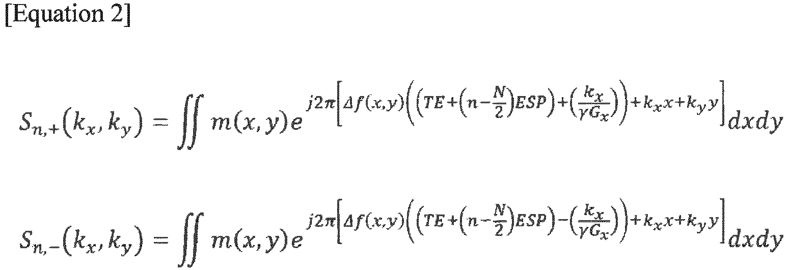
- In Equation 2, S n,+(kx ,ky ) denotes a k-space in which even scane lines are collected, and S n,-(kx,ky ) denotes a k-space in which odd scan lines are collected. The two separate k-spaces include missing odd scan lines and missing even scan lines, respectively, and thus may be regarded as being downsampled by a factor of 2. Accordingly, the method of reconstructing a magnetic resonance image may change into an issue of filling in the missing portions of the k-spaces.
- One equation in Equation 2 may be subtracted from the other equation, as expressed by Equation 3.

- In a case in which the frequency offset is sufficiently insignificant, Equation 3 may be approximated as expressed by Equation 4.

- Equation 4 may be the same as a result of performing Fourier transform on a gradient of a product of an RF offset and an image. Since A(x,y)Δf(x,y) has a smooth gradient and Sn,Δ(kx ,ky ) and has a sparse density, a difference S n,Δ between the k-space using the odd lines and the k-space using the even lines may be sparse. A Hankel matrix constructed based on Sn,Δ(kx ,ky ) may be ranked low. Accordingly, an annihilation filterthat satisfies Equation 5 may be present.


- In Equation 5,
 denotes a vectorized form of a two-dimensional (2D) annihilation filter. In this example, S n,Δ = S n,- - S n,+ is satisfied and thus, a relationship as expressed by Equation 6 may be obtained.
- Accordingly, a matrixmay be generated by constructing respective block Hankel matrices from the k-space including the even scan lines and the k-space including the odd scan lines and combining the two matrices. A low rankness of the matrix Y may be used to fill in the missing portions of the data.

- When the missing portions of S n,+ and S n,- are filled in and reconstructed, a final image without ghost artifacts may be generated by combining the reconstructed even scan line image and the reconstructed odd scan line image. In this example, the reconstructed even scan line image and the odd scan line image may be combined using a sum of squares.
- In a case of using multi-coil data, restoration may be performed similarly by constructing a Hankel matrix, as expressed by Equation 6.

- In Equation 7,(i) denotes a Hankel matrix at an i-th coil.
-
FIG. 4 illustrates a method of constructing block Hankel matrices from a k-space in which data is insufficient according to an embodiment. - Referring to
FIG. 4 , patches 411, 412, 413, 414, and 415 may be extracted from a k-space 410 of an EPI image. Here, each patch includes filled odd scan lines and missing even scan lines. - In this example, an apparatus for reconstructing a magnetic resonance image may construct a Hankel matrix or Hankel matrices for each patch. In detail, the apparatus for reconstructing a magnetic resonance image may construct a
Hankel matrix 421 for the patch 411,Hankel matrices Hankel matrices Hankel matrices Hankel matrix 429 for the patch 415. Rank deficiency of the Hankel matrices may be used to reconstruct data of the missing portions. -
FIG. 5 illustrates a result of constructing a block Hankel matrix from each of an even scan line image and an odd scan line image according to an embodiment. - Referring to
FIG. 5 , aHankel matrix 521 may be constructed fromEPI data 511, and aHankel matrix 522 may be constructed fromEPI data 512. - An apparatus for reconstructing a magnetic resonance image may fill in and reconstruct missing portions in each of the
Hankel matrices -
FIG. 6 illustrates a change in size of a reconstructed patch at each level of a pyramidal structure according to an embodiment. - Referring to
FIG. 6 , a low rank completion algorithm may be calculated efficiently through a pyramid-structured scheme. The low rank completion algorithm may be calculated with respect to an independent patch. By using the pyramidal structure as shown inFIG. 6 , a size of a patch may be reduced for each operation, and reconstruction may be performed differently based on a signal-to-noise ratio (SNR) for each operation, whereby a number of interactions of an iterative reconstruction-based low rank matrix completion algorithm may be reduced. Such a pyramidal structure may apply to a kx-ky domain. - A
patch 610 in a first operation and apatch 620 in a second operation are illustrated. In this example, as advancing to a subsequent operation, an x-axial length of a patch may be reduced to half a length of a patch in a previous operation. Since acenter 611 of each patch includes a low-frequency portion at all times, reconstruction may be performed more precisely without noise as advancing to a subsequent operation. Thus, a number of iterations of a low rank matrix completion algorithm may decrease, and reconstructed data of a previous operation may be used as an initial value of each operation, whereby more accurate result values may be obtained. - In another example, a length and a width of a patch may be reduced to those of a patch in a previous operation.
-
FIG. 7 is a flowchart illustrating a reconstruction process to which a pyramidal structure is applied according to an embodiment. - In
operation 710, an apparatus for reconstructing a magnetic resonance image may separate an even scan line image and an odd scan line image from a k-space of an EPI image. - In
operation 720, the apparatus for reconstructing a magnetic resonance image may determine a pyramid patch. The apparatus for reconstructing a magnetic resonance image may reconstruct the even scan line image and the odd scan line image through a matrix completion algorithm, and reduce a size of the pyramid patch. - In
operation 730, the apparatus for reconstructing a magnetic resonance image may construct Hankel matrices of the k-space from the even scan line image and the odd scan line image. - In
operation 740, the apparatus for reconstructing a magnetic resonance image may reconstruct an image through a low rank matrix completion algorithm. The apparatus for reconstructing a magnetic resonance image may reconstruct a low-frequency domain of the k-space through the matrix completion algorithm using values of the restored even scan line image and the restored odd scan line image as initial values. - In
operation 750, the apparatus for reconstructing a magnetic resonance image may determine whether a pyramid level reaches a desired level. - In this example,
operations 720 through 740 may be iteratively performed until the pyramid level reaches the desired level while reducing a size of a patch to half a size of a previous patch that is yet to undergooperation 750. - In a reconstruction process to which a pyramidal structure is applied, reconstruction may be performed differently based on an SNR for each level and for each operation, whereby a number of interactions of an iterative reconstruction-based low rank matrix completion algorithm may be reduced.
-
FIGS. 8A and8B illustrate results of a method of reconstructing a magnetic resonance image according to an embodiment. - Referring to
FIG. 8A , magnetic resonance images viewed from aside 811, a front 812, and a top 813 according to a conventional or related art include ghost artifacts, whereas magnetic resonance images viewed from aside 821, a front 822, and a top 823 according to an embodiment do not include ghost artifacts. - Referring to
FIG. 8B , amagnetic resonance image 831 according to a conventional or related art includes ghost artifacts (pointed by an arrow), whereas magnetic resonance images according to an embodiment, in detail, both a single-coil image 832 and amulti-coil image 833, do not include ghost artifacts. - The units and/or modules described herein may be implemented using hardware components and software components. For example, the hardware components may include microphones, amplifiers, band-pass filters, audio to digital convertors, and processing devices. A processing device may be implemented using one or more hardware device configured to carry out and/or execute program code by performing arithmetical, logical, and input/output operations. The processing device(s) may include a processor, a controller and an arithmetic logic unit, a digital signal processor, a microcomputer, a field programmable array, a programmable logic unit, a microprocessor or any other device capable of responding to and executing instructions in a defined manner. The processing device may run an operating system (OS) and one or more software applications that run on the OS. The processing device also may access, store, manipulate, process, and create data in response to execution of the software. For purpose of simplicity, the description of a processing device is used as singular; however, one skilled in the art will appreciated that a processing device may include multiple processing elements and multiple types of processing elements. For example, a processing device may include multiple processors or a processor and a controller. In addition, different processing configurations are possible, such as parallel processors.
- The software may include a computer program, a piece of code, an instruction, or some combination thereof, to independently or collectively instruct and/or configure the processing device to operate as desired, thereby transforming the processing device into a special purpose processor. Software and data may be embodied permanently or temporarily in any type of machine, component, physical or virtual equipment, computer storage medium or device, or in a propagated signal wave capable of providing instructions or data to or being interpreted by the processing device. The software also may be distributed over network coupled computer systems so that the software is stored and executed in a distributed fashion. The software and data may be stored by one or more non-transitory computer readable recording mediums.
- The methods according to the above-described embodiments may be recorded in non-transitory computer-readable media including program instructions to implement various operations of the above-described embodiments. The media may also include, alone or in combination with the program instructions, data files, data structures, and the like. The program instructions recorded on the media may be those specially designed and constructed for the purposes of embodiments, or they may be of the kind well-known and available to those having skill in the computer software arts. Examples of non-transitory computer-readable media include magnetic media such as hard disks, floppy disks, and magnetic tape; optical media such as CD-ROM discs, DVDs, and/or Blue-ray discs; magneto-optical media such as optical discs; and hardware devices that are specially configured to store and perform program instructions, such as read-only memory (ROM), random access memory (RAM), flash memory (e.g., USB flash drives, memory cards, memory sticks, etc.), and the like. Examples of program instructions include both machine code, such as produced by a compiler, and files containing higher level code that may be executed by the computer using an interpreter. The above-described devices may be configured to act as one or more software modules in order to perform the operations of the above-described embodiments, or vice versa.
- A number of embodiments have been described above. Nevertheless, it should be understood that various modifications may be made to these embodiments. For example, suitable results may be achieved if the described techniques are performed in a different order and/or if components in a described system, architecture, device, or circuit are combined in a different manner and/or replaced or supplemented by other components or their equivalents. Accordingly, other implementations are within the scope of the following claim.
Claims (20)
- A method of reconstructing a magnetic resonance image, the method comprising:receiving echo planar imaging (EPI) data;acquiring an even scan line image and an odd scan line image from k-space data of the EPI data; andreconstructing missing portions of the even scan line image and the odd scan line image.
- The method of claim 1, wherein the reconstructing of the missing portions of the even scan line image and the odd scan line image comprises reconstructing the missing portions by constructing block Hankel matrices from the even scan line image and the odd scan line image based on a presence of an annihilation filter in a k-space and interpolating Fourier data yet to be measured through a low rank matrix completion algorithm.
- The method of claim 2, wherein the reconstructing of the missing portions by constructing the block Hankel matrices from the even scan line image and the odd scan line image comprises transforming the even scan line image and the odd scan line image into the block Hankel matrices using a commutative rule of a convolution operation of the k-space and the annihilation filter in a frequency domain.
- The method of claim 1, further comprising:
generating a single reconstructed image by combining the reconstructed even scan line image and the reconstructed odd scan line image. - The method of claim 4, wherein the generating of the single reconstructed image comprises generating the single reconstructed image using a sum of squares of the reconstructed even scan line image and the reconstructed odd scan line image.
- The method of claim 1, wherein the reconstructing of the missing portions of the even scan line image and the odd scan line image comprises reconstructing the even scan line image and the odd scan line image using a plurality of minimum rank matrix completion algorithms after changing pyramid patches, each having a pyramidal structure, into block Hankel matrices.
- The method of claim 6, wherein the reconstructing of the even scan line image and the odd scan line image comprises reconstructing the even scan line image and the odd scan line image through the matrix completion algorithms, reducing sizes of the pyramid patches, and reconstructing a low-frequency domain of a k-space through the matrix completion algorithms using values of the reconstructed even scan line image and the reconstructed odd scan line image as initial values.
- The method of claim 6, wherein the reconstructing of the even scan line image and the odd scan line image comprises applying a stop reference less than or equal to a preset reference to a pyramid patch including noise greater than or equal to the preset reference, and applying a stop reference greater than or equal to the preset reference to a pyramid patch from which a low-frequency domain is cut off, among the pyramid patches, each having the pyramidal structure.
- The method of claim 1, wherein the EPI data comprises at least one of single-coil EPI data or multi-coil EPI data.
- The method of claim 1, wherein the reconstructing of the missing portions of the even scan line image and the odd scan line image comprises reconstructing the missing portions by assigning a weighting to a k-space of each of the even scan line image and the odd scan line image and constructing block Hankel matrices from the weighted even scan line image and the weighted odd scan line image.
- A computer program combined with hardware and stored in a non-transitory computer-readable storage medium to cause a computer to perform the method of claim 1.
- An apparatus for reconstructing a magnetic resonance image, the apparatus comprising:
a processor configured to acquire an even scan line image and an odd scan line image from k-space data of echo planar imaging (EPI) data, and reconstruct missing portions of the even scan line image and the odd scan line image. - The apparatus of claim 12, wherein the processor is configured to reconstruct the missing portions by constructing block Hankel matrices from the even scan line image and the odd scan line image based on a presence of an annihilation filter in a k-space and interpolating Fourier data yet to be measured through a low rank matrix completion algorithm.
- The apparatus of claim 13, wherein the processor is configured to transform the even scan line image and the odd scan line image into the block Hankel matrices using a commutative rule of a convolution operation of the k-space and the annihilation filter in a frequency domain.
- The apparatus of claim 12, wherein the processor is configured to generate a single reconstructed image by combining the reconstructed even scan line image and the reconstructed odd scan line image.
- The apparatus of claim 15, wherein the processor is configured to generate the single reconstructed image using a sum of squares of the reconstructed even scan line image and the reconstructed odd scan line image.
- The apparatus of claim 12, wherein the processor is configured to reconstruct the even scan line image and the odd scan line image using a plurality of minimum rank matrix completion algorithms after changing pyramid patches, each having a pyramidal structure, into block Hankel matrices.
- The apparatus of claim 17, wherein the processor is configured to reconstruct the even scan line image and the odd scan line image through the matrix completion algorithms, reduce sizes of the pyramid patches, and reconstruct a low-frequency domain of a k-space through the matrix completion algorithms using values of the reconstructed even scan line image and the reconstructed odd scan line image as initial values.
- The apparatus of claim 12, wherein the processor is configured to apply a stop reference less than or equal to a preset reference to a pyramid patch including noise greater than or equal to the preset reference, and apply a stop reference greater than or equal to the preset reference to a pyramid patch from which a low-frequency domain is cut off, among the pyramid patches, each having the pyramidal structure.
- The apparatus of claim 12, wherein the processor is configured to reconstruct the missing portions by assigning a weighting to a k-space of each of the even scan line image and the odd scan line image and constructing block Hankel matrices from the weighted even scan line image and the weighted odd scan line image.
Applications Claiming Priority (2)
| Application Number | Priority Date | Filing Date | Title |
|---|---|---|---|
| KR1020150146208A KR101697872B1 (en) | 2015-10-20 | 2015-10-20 | Method to remove ghost artifacts in magnetic resonance images, and magnetic resonance apparatus for this |
| PCT/KR2016/001279 WO2017069347A1 (en) | 2015-10-20 | 2016-02-05 | Method for removing ghost artifact from magnetic resonance image and magnetic resonance device therefor |
Publications (3)
| Publication Number | Publication Date |
|---|---|
| EP3366209A1 true EP3366209A1 (en) | 2018-08-29 |
| EP3366209A4 EP3366209A4 (en) | 2018-11-07 |
| EP3366209B1 EP3366209B1 (en) | 2022-01-12 |
Family
ID=57992085
Family Applications (1)
| Application Number | Title | Priority Date | Filing Date |
|---|---|---|---|
| EP16857605.6A Active EP3366209B1 (en) | 2015-10-20 | 2016-02-05 | Method for removing ghost artifact from magnetic resonance image and magnetic resonance device therefor |
Country Status (5)
| Country | Link |
|---|---|
| US (1) | US10627469B2 (en) |
| EP (1) | EP3366209B1 (en) |
| KR (1) | KR101697872B1 (en) |
| CN (1) | CN107205686B (en) |
| WO (1) | WO2017069347A1 (en) |
Families Citing this family (7)
| Publication number | Priority date | Publication date | Assignee | Title |
|---|---|---|---|---|
| US10802096B2 (en) * | 2017-12-26 | 2020-10-13 | Uih America, Inc. | Methods and systems for magnetic resonance imaging |
| KR102131505B1 (en) * | 2018-08-29 | 2020-07-07 | 한국과학기술원 | Methoed for removing ghost artifact of echo planar imaging by using neural network and apparatus therefor |
| KR102066009B1 (en) * | 2018-09-14 | 2020-01-14 | 가천대학교 산학협력단 | Image reconstruction system on medical imaging apparatus using recurrent neural network |
| US10705170B1 (en) * | 2019-02-15 | 2020-07-07 | GE Precision Healthcare LLC | Methods and systems for removing spike noise in magnetic resonance imaging |
| US12085631B2 (en) * | 2019-04-26 | 2024-09-10 | May Foundation For Medical Education And Research | Model-based iterative reconstruction for magnetic resonance imaging with echo planar readout |
| WO2021167124A1 (en) * | 2020-02-19 | 2021-08-26 | 서울대학교 산학협력단 | Mri data conversion device including conversion network unit using mri data and additional information, and mri data conversion method using same |
| KR102472546B1 (en) * | 2021-08-12 | 2022-11-30 | 주식회사 에어스메디컬 | Magnetic resonance image processing apparatus and method to which noise-to-noise technique is applied |
Family Cites Families (8)
| Publication number | Priority date | Publication date | Assignee | Title |
|---|---|---|---|---|
| US5910728A (en) * | 1996-11-12 | 1999-06-08 | Beth Israel Deaconess Medical Center | Simultaneous acquisition of spatial harmonics (SMASH): ultra-fast imaging with radiofrequency coil arrays |
| GB9726143D0 (en) * | 1997-12-10 | 1998-02-11 | Chapman Barry L | Ghost artifact reduction |
| DE10353342B4 (en) * | 2003-11-14 | 2008-07-17 | Siemens Ag | Improved MRI imaging based on conventional PPA reconstruction techniques |
| JP2008154887A (en) * | 2006-12-26 | 2008-07-10 | Ge Medical Systems Global Technology Co Llc | Mri apparatus |
| JP5063279B2 (en) * | 2007-09-27 | 2012-10-31 | 株式会社日立製作所 | Magnetic resonance equipment |
| KR20120138478A (en) * | 2011-06-15 | 2012-12-26 | 삼성메디슨 주식회사 | Ultrasound imaging apparatus and method using synthetic aperture imaging |
| KR20140122991A (en) * | 2013-04-11 | 2014-10-21 | 삼성전자주식회사 | Medical imaging apparatus and control method for the same |
| DE102013220012B4 (en) * | 2013-10-02 | 2015-04-30 | Siemens Aktiengesellschaft | Image reconstruction with multiple virtual coils |
-
2015
- 2015-10-20 KR KR1020150146208A patent/KR101697872B1/en active Active
-
2016
- 2016-02-05 WO PCT/KR2016/001279 patent/WO2017069347A1/en not_active Ceased
- 2016-02-05 US US15/323,644 patent/US10627469B2/en active Active
- 2016-02-05 EP EP16857605.6A patent/EP3366209B1/en active Active
- 2016-02-05 CN CN201680002068.0A patent/CN107205686B/en active Active
Also Published As
| Publication number | Publication date |
|---|---|
| CN107205686B (en) | 2020-08-07 |
| EP3366209B1 (en) | 2022-01-12 |
| EP3366209A4 (en) | 2018-11-07 |
| KR101697872B1 (en) | 2017-01-18 |
| US20170299680A1 (en) | 2017-10-19 |
| CN107205686A (en) | 2017-09-26 |
| US10627469B2 (en) | 2020-04-21 |
| WO2017069347A1 (en) | 2017-04-27 |
Similar Documents
| Publication | Publication Date | Title |
|---|---|---|
| EP3366209B1 (en) | Method for removing ghost artifact from magnetic resonance image and magnetic resonance device therefor | |
| CN112396560B (en) | Systems and methods for deblurring medical images using deep neural networks | |
| US11181598B2 (en) | Multi-contrast MRI image reconstruction using machine learning | |
| Knoll et al. | Parallel imaging with nonlinear reconstruction using variational penalties | |
| US9964618B2 (en) | Magnetic resonance imaging system and magnetic resonance imaging method using excited sub-volumes in groups | |
| CN104749538B (en) | A kind of parallel MR imaging Phase Processing method | |
| Haldar et al. | Fast submillimeter diffusion MRI using gSlider‐SMS and SNR‐enhancing joint reconstruction | |
| CN103907109B (en) | Fast numerical for image procossing purpose wave filter application convolution is approached | |
| CN113924503B (en) | Determination of parameter maps in time-domain magnetic resonance | |
| JP2017516551A5 (en) | ||
| US10204412B2 (en) | Magnetic resonance imaging apparatus, medical image processing device, and image processing method | |
| WO2014189925A1 (en) | System and method for reducing acoustic noise level in mr imaging | |
| JP6762284B2 (en) | Magnetic resonance imaging device and noise removal method | |
| CN113994225A (en) | System and method for image reconstruction in magnetic resonance imaging | |
| KR20200025179A (en) | Methoed for removing ghost artifact of echo planar imaging by using neural network and apparatus therefor | |
| JP2015533531A5 (en) | ||
| US20150091570A1 (en) | Method and magnetic resonance apparatus for image reconstruction with multiple virtual coils | |
| Cheng et al. | Improved parallel image reconstruction using feature refinement | |
| CN117562529A (en) | Magnetic resonance imaging methods, devices, magnetic resonance equipment and storage media | |
| Curtis et al. | Random volumetric MRI trajectories via genetic algorithms | |
| US12625211B2 (en) | Model-based reconstruction for looping-star pulse sequences in MRI | |
| Ito et al. | Deep-Learning-Based Magnetic Resonance Simultaneous Multislice Imaging Using Holographic Image Decoding | |
| US20260072112A1 (en) | Undersampled Point Restoration Method, Device and Magnetic Resonance Imaging System in Magnetic Resonance Imaging | |
| CN110068782A (en) | Artifact in quick three-dimensional spin-echo sequence avoids | |
| Schultz | Iterative Reconstruction in PatLoc Imaging |
Legal Events
| Date | Code | Title | Description |
|---|---|---|---|
| STAA | Information on the status of an ep patent application or granted ep patent |
Free format text: STATUS: THE INTERNATIONAL PUBLICATION HAS BEEN MADE |
|
| PUAI | Public reference made under article 153(3) epc to a published international application that has entered the european phase |
Free format text: ORIGINAL CODE: 0009012 |
|
| STAA | Information on the status of an ep patent application or granted ep patent |
Free format text: STATUS: REQUEST FOR EXAMINATION WAS MADE |
|
| 17P | Request for examination filed |
Effective date: 20180420 |
|
| AK | Designated contracting states |
Kind code of ref document: A1 Designated state(s): AL AT BE BG CH CY CZ DE DK EE ES FI FR GB GR HR HU IE IS IT LI LT LU LV MC MK MT NL NO PL PT RO RS SE SI SK SM TR |
|
| AX | Request for extension of the european patent |
Extension state: BA ME |
|
| REG | Reference to a national code |
Ref country code: DE Ref legal event code: R079 Ref document number: 602016068385 Country of ref document: DE Free format text: PREVIOUS MAIN CLASS: A61B0005055000 Ipc: G01R0033561000 |
|
| A4 | Supplementary search report drawn up and despatched |
Effective date: 20181008 |
|
| RIC1 | Information provided on ipc code assigned before grant |
Ipc: G01R 33/565 20060101ALI20181001BHEP Ipc: G01R 33/561 20060101AFI20181001BHEP Ipc: A61B 5/055 20060101ALI20181001BHEP |
|
| DAV | Request for validation of the european patent (deleted) | ||
| DAX | Request for extension of the european patent (deleted) | ||
| GRAP | Despatch of communication of intention to grant a patent |
Free format text: ORIGINAL CODE: EPIDOSNIGR1 |
|
| STAA | Information on the status of an ep patent application or granted ep patent |
Free format text: STATUS: GRANT OF PATENT IS INTENDED |
|
| INTG | Intention to grant announced |
Effective date: 20210920 |
|
| GRAS | Grant fee paid |
Free format text: ORIGINAL CODE: EPIDOSNIGR3 |
|
| GRAA | (expected) grant |
Free format text: ORIGINAL CODE: 0009210 |
|
| STAA | Information on the status of an ep patent application or granted ep patent |
Free format text: STATUS: THE PATENT HAS BEEN GRANTED |
|
| AK | Designated contracting states |
Kind code of ref document: B1 Designated state(s): AL AT BE BG CH CY CZ DE DK EE ES FI FR GB GR HR HU IE IS IT LI LT LU LV MC MK MT NL NO PL PT RO RS SE SI SK SM TR |
|
| REG | Reference to a national code |
Ref country code: GB Ref legal event code: FG4D |
|
| REG | Reference to a national code |
Ref country code: CH Ref legal event code: EP |
|
| REG | Reference to a national code |
Ref country code: IE Ref legal event code: FG4D |
|
| REG | Reference to a national code |
Ref country code: DE Ref legal event code: R096 Ref document number: 602016068385 Country of ref document: DE |
|
| REG | Reference to a national code |
Ref country code: AT Ref legal event code: REF Ref document number: 1462735 Country of ref document: AT Kind code of ref document: T Effective date: 20220215 |
|
| REG | Reference to a national code |
Ref country code: LT Ref legal event code: MG9D |
|
| REG | Reference to a national code |
Ref country code: NL Ref legal event code: MP Effective date: 20220112 |
|
| REG | Reference to a national code |
Ref country code: AT Ref legal event code: MK05 Ref document number: 1462735 Country of ref document: AT Kind code of ref document: T Effective date: 20220112 |
|
| PG25 | Lapsed in a contracting state [announced via postgrant information from national office to epo] |
Ref country code: NL Free format text: LAPSE BECAUSE OF FAILURE TO SUBMIT A TRANSLATION OF THE DESCRIPTION OR TO PAY THE FEE WITHIN THE PRESCRIBED TIME-LIMIT Effective date: 20220112 |
|
| PG25 | Lapsed in a contracting state [announced via postgrant information from national office to epo] |
Ref country code: SE Free format text: LAPSE BECAUSE OF FAILURE TO SUBMIT A TRANSLATION OF THE DESCRIPTION OR TO PAY THE FEE WITHIN THE PRESCRIBED TIME-LIMIT Effective date: 20220112 Ref country code: RS Free format text: LAPSE BECAUSE OF FAILURE TO SUBMIT A TRANSLATION OF THE DESCRIPTION OR TO PAY THE FEE WITHIN THE PRESCRIBED TIME-LIMIT Effective date: 20220112 Ref country code: PT Free format text: LAPSE BECAUSE OF FAILURE TO SUBMIT A TRANSLATION OF THE DESCRIPTION OR TO PAY THE FEE WITHIN THE PRESCRIBED TIME-LIMIT Effective date: 20220512 Ref country code: NO Free format text: LAPSE BECAUSE OF FAILURE TO SUBMIT A TRANSLATION OF THE DESCRIPTION OR TO PAY THE FEE WITHIN THE PRESCRIBED TIME-LIMIT Effective date: 20220412 Ref country code: LT Free format text: LAPSE BECAUSE OF FAILURE TO SUBMIT A TRANSLATION OF THE DESCRIPTION OR TO PAY THE FEE WITHIN THE PRESCRIBED TIME-LIMIT Effective date: 20220112 Ref country code: HR Free format text: LAPSE BECAUSE OF FAILURE TO SUBMIT A TRANSLATION OF THE DESCRIPTION OR TO PAY THE FEE WITHIN THE PRESCRIBED TIME-LIMIT Effective date: 20220112 Ref country code: ES Free format text: LAPSE BECAUSE OF FAILURE TO SUBMIT A TRANSLATION OF THE DESCRIPTION OR TO PAY THE FEE WITHIN THE PRESCRIBED TIME-LIMIT Effective date: 20220112 Ref country code: BG Free format text: LAPSE BECAUSE OF FAILURE TO SUBMIT A TRANSLATION OF THE DESCRIPTION OR TO PAY THE FEE WITHIN THE PRESCRIBED TIME-LIMIT Effective date: 20220412 |
|
| PG25 | Lapsed in a contracting state [announced via postgrant information from national office to epo] |
Ref country code: PL Free format text: LAPSE BECAUSE OF FAILURE TO SUBMIT A TRANSLATION OF THE DESCRIPTION OR TO PAY THE FEE WITHIN THE PRESCRIBED TIME-LIMIT Effective date: 20220112 Ref country code: LV Free format text: LAPSE BECAUSE OF FAILURE TO SUBMIT A TRANSLATION OF THE DESCRIPTION OR TO PAY THE FEE WITHIN THE PRESCRIBED TIME-LIMIT Effective date: 20220112 Ref country code: GR Free format text: LAPSE BECAUSE OF FAILURE TO SUBMIT A TRANSLATION OF THE DESCRIPTION OR TO PAY THE FEE WITHIN THE PRESCRIBED TIME-LIMIT Effective date: 20220413 Ref country code: FI Free format text: LAPSE BECAUSE OF FAILURE TO SUBMIT A TRANSLATION OF THE DESCRIPTION OR TO PAY THE FEE WITHIN THE PRESCRIBED TIME-LIMIT Effective date: 20220112 Ref country code: AT Free format text: LAPSE BECAUSE OF FAILURE TO SUBMIT A TRANSLATION OF THE DESCRIPTION OR TO PAY THE FEE WITHIN THE PRESCRIBED TIME-LIMIT Effective date: 20220112 |
|
| PG25 | Lapsed in a contracting state [announced via postgrant information from national office to epo] |
Ref country code: IS Free format text: LAPSE BECAUSE OF FAILURE TO SUBMIT A TRANSLATION OF THE DESCRIPTION OR TO PAY THE FEE WITHIN THE PRESCRIBED TIME-LIMIT Effective date: 20220512 |
|
| REG | Reference to a national code |
Ref country code: DE Ref legal event code: R097 Ref document number: 602016068385 Country of ref document: DE |
|
| REG | Reference to a national code |
Ref country code: CH Ref legal event code: PL |
|
| REG | Reference to a national code |
Ref country code: BE Ref legal event code: MM Effective date: 20220228 |
|
| PG25 | Lapsed in a contracting state [announced via postgrant information from national office to epo] |
Ref country code: SM Free format text: LAPSE BECAUSE OF FAILURE TO SUBMIT A TRANSLATION OF THE DESCRIPTION OR TO PAY THE FEE WITHIN THE PRESCRIBED TIME-LIMIT Effective date: 20220112 Ref country code: SK Free format text: LAPSE BECAUSE OF FAILURE TO SUBMIT A TRANSLATION OF THE DESCRIPTION OR TO PAY THE FEE WITHIN THE PRESCRIBED TIME-LIMIT Effective date: 20220112 Ref country code: RO Free format text: LAPSE BECAUSE OF FAILURE TO SUBMIT A TRANSLATION OF THE DESCRIPTION OR TO PAY THE FEE WITHIN THE PRESCRIBED TIME-LIMIT Effective date: 20220112 Ref country code: MC Free format text: LAPSE BECAUSE OF FAILURE TO SUBMIT A TRANSLATION OF THE DESCRIPTION OR TO PAY THE FEE WITHIN THE PRESCRIBED TIME-LIMIT Effective date: 20220112 Ref country code: LU Free format text: LAPSE BECAUSE OF NON-PAYMENT OF DUE FEES Effective date: 20220205 Ref country code: EE Free format text: LAPSE BECAUSE OF FAILURE TO SUBMIT A TRANSLATION OF THE DESCRIPTION OR TO PAY THE FEE WITHIN THE PRESCRIBED TIME-LIMIT Effective date: 20220112 Ref country code: DK Free format text: LAPSE BECAUSE OF FAILURE TO SUBMIT A TRANSLATION OF THE DESCRIPTION OR TO PAY THE FEE WITHIN THE PRESCRIBED TIME-LIMIT Effective date: 20220112 Ref country code: CZ Free format text: LAPSE BECAUSE OF FAILURE TO SUBMIT A TRANSLATION OF THE DESCRIPTION OR TO PAY THE FEE WITHIN THE PRESCRIBED TIME-LIMIT Effective date: 20220112 |
|
| PLBE | No opposition filed within time limit |
Free format text: ORIGINAL CODE: 0009261 |
|
| STAA | Information on the status of an ep patent application or granted ep patent |
Free format text: STATUS: NO OPPOSITION FILED WITHIN TIME LIMIT |
|
| PG25 | Lapsed in a contracting state [announced via postgrant information from national office to epo] |
Ref country code: AL Free format text: LAPSE BECAUSE OF FAILURE TO SUBMIT A TRANSLATION OF THE DESCRIPTION OR TO PAY THE FEE WITHIN THE PRESCRIBED TIME-LIMIT Effective date: 20220112 |
|
| 26N | No opposition filed |
Effective date: 20221013 |
|
| GBPC | Gb: european patent ceased through non-payment of renewal fee |
Effective date: 20220412 |
|
| PG25 | Lapsed in a contracting state [announced via postgrant information from national office to epo] |
Ref country code: LI Free format text: LAPSE BECAUSE OF NON-PAYMENT OF DUE FEES Effective date: 20220228 Ref country code: IE Free format text: LAPSE BECAUSE OF NON-PAYMENT OF DUE FEES Effective date: 20220205 Ref country code: GB Free format text: LAPSE BECAUSE OF NON-PAYMENT OF DUE FEES Effective date: 20220412 Ref country code: FR Free format text: LAPSE BECAUSE OF NON-PAYMENT OF DUE FEES Effective date: 20220312 Ref country code: CH Free format text: LAPSE BECAUSE OF NON-PAYMENT OF DUE FEES Effective date: 20220228 |
|
| PG25 | Lapsed in a contracting state [announced via postgrant information from national office to epo] |
Ref country code: SI Free format text: LAPSE BECAUSE OF FAILURE TO SUBMIT A TRANSLATION OF THE DESCRIPTION OR TO PAY THE FEE WITHIN THE PRESCRIBED TIME-LIMIT Effective date: 20220112 Ref country code: BE Free format text: LAPSE BECAUSE OF NON-PAYMENT OF DUE FEES Effective date: 20220228 |
|
| PG25 | Lapsed in a contracting state [announced via postgrant information from national office to epo] |
Ref country code: IT Free format text: LAPSE BECAUSE OF FAILURE TO SUBMIT A TRANSLATION OF THE DESCRIPTION OR TO PAY THE FEE WITHIN THE PRESCRIBED TIME-LIMIT Effective date: 20220112 |
|
| PG25 | Lapsed in a contracting state [announced via postgrant information from national office to epo] |
Ref country code: HU Free format text: LAPSE BECAUSE OF FAILURE TO SUBMIT A TRANSLATION OF THE DESCRIPTION OR TO PAY THE FEE WITHIN THE PRESCRIBED TIME-LIMIT; INVALID AB INITIO Effective date: 20160205 |
|
| PG25 | Lapsed in a contracting state [announced via postgrant information from national office to epo] |
Ref country code: MK Free format text: LAPSE BECAUSE OF FAILURE TO SUBMIT A TRANSLATION OF THE DESCRIPTION OR TO PAY THE FEE WITHIN THE PRESCRIBED TIME-LIMIT Effective date: 20220112 Ref country code: CY Free format text: LAPSE BECAUSE OF FAILURE TO SUBMIT A TRANSLATION OF THE DESCRIPTION OR TO PAY THE FEE WITHIN THE PRESCRIBED TIME-LIMIT Effective date: 20220112 |
|
| PG25 | Lapsed in a contracting state [announced via postgrant information from national office to epo] |
Ref country code: TR Free format text: LAPSE BECAUSE OF FAILURE TO SUBMIT A TRANSLATION OF THE DESCRIPTION OR TO PAY THE FEE WITHIN THE PRESCRIBED TIME-LIMIT Effective date: 20220112 |
|
| PG25 | Lapsed in a contracting state [announced via postgrant information from national office to epo] |
Ref country code: MT Free format text: LAPSE BECAUSE OF FAILURE TO SUBMIT A TRANSLATION OF THE DESCRIPTION OR TO PAY THE FEE WITHIN THE PRESCRIBED TIME-LIMIT Effective date: 20220112 |
|
| PGFP | Annual fee paid to national office [announced via postgrant information from national office to epo] |
Ref country code: DE Payment date: 20260205 Year of fee payment: 11 |