EP3366189A1 - Endoscope - Google Patents
Endoscope Download PDFInfo
- Publication number
- EP3366189A1 EP3366189A1 EP16866373.0A EP16866373A EP3366189A1 EP 3366189 A1 EP3366189 A1 EP 3366189A1 EP 16866373 A EP16866373 A EP 16866373A EP 3366189 A1 EP3366189 A1 EP 3366189A1
- Authority
- EP
- European Patent Office
- Prior art keywords
- wire
- linear member
- insertion portion
- wires
- coil pipe
- Prior art date
- Legal status (The legal status is an assumption and is not a legal conclusion. Google has not performed a legal analysis and makes no representation as to the accuracy of the status listed.)
- Withdrawn
Links
- 238000003780 insertion Methods 0.000 claims abstract description 41
- 230000037431 insertion Effects 0.000 claims abstract description 41
- 238000009954 braiding Methods 0.000 claims abstract description 5
- 238000005452 bending Methods 0.000 claims description 27
- 238000004804 winding Methods 0.000 claims description 4
- 239000011347 resin Substances 0.000 claims 1
- 229920005989 resin Polymers 0.000 claims 1
- 230000006835 compression Effects 0.000 description 6
- 238000007906 compression Methods 0.000 description 6
- 239000000853 adhesive Substances 0.000 description 5
- 230000001070 adhesive effect Effects 0.000 description 5
- 238000005219 brazing Methods 0.000 description 5
- 238000005476 soldering Methods 0.000 description 5
- 239000000956 alloy Substances 0.000 description 4
- 229910045601 alloy Inorganic materials 0.000 description 4
- 239000002184 metal Substances 0.000 description 4
- 238000002604 ultrasonography Methods 0.000 description 2
- 239000000470 constituent Substances 0.000 description 1
- 238000010276 construction Methods 0.000 description 1
- 239000012530 fluid Substances 0.000 description 1
- 238000005286 illumination Methods 0.000 description 1
- 239000000463 material Substances 0.000 description 1
- 238000000034 method Methods 0.000 description 1
- 230000003287 optical effect Effects 0.000 description 1
- 230000002265 prevention Effects 0.000 description 1
- 229920003002 synthetic resin Polymers 0.000 description 1
- 239000000057 synthetic resin Substances 0.000 description 1
Images

Classifications
-
- G—PHYSICS
- G02—OPTICS
- G02B—OPTICAL ELEMENTS, SYSTEMS OR APPARATUS
- G02B23/00—Telescopes, e.g. binoculars; Periscopes; Instruments for viewing the inside of hollow bodies; Viewfinders; Optical aiming or sighting devices
- G02B23/24—Instruments or systems for viewing the inside of hollow bodies, e.g. fibrescopes
- G02B23/2476—Non-optical details, e.g. housings, mountings, supports
-
- A—HUMAN NECESSITIES
- A61—MEDICAL OR VETERINARY SCIENCE; HYGIENE
- A61B—DIAGNOSIS; SURGERY; IDENTIFICATION
- A61B1/00—Instruments for performing medical examinations of the interior of cavities or tubes of the body by visual or photographical inspection, e.g. endoscopes; Illuminating arrangements therefor
-
- A—HUMAN NECESSITIES
- A61—MEDICAL OR VETERINARY SCIENCE; HYGIENE
- A61B—DIAGNOSIS; SURGERY; IDENTIFICATION
- A61B1/00—Instruments for performing medical examinations of the interior of cavities or tubes of the body by visual or photographical inspection, e.g. endoscopes; Illuminating arrangements therefor
- A61B1/00064—Constructional details of the endoscope body
- A61B1/00071—Insertion part of the endoscope body
- A61B1/00078—Insertion part of the endoscope body with stiffening means
-
- A—HUMAN NECESSITIES
- A61—MEDICAL OR VETERINARY SCIENCE; HYGIENE
- A61B—DIAGNOSIS; SURGERY; IDENTIFICATION
- A61B1/00—Instruments for performing medical examinations of the interior of cavities or tubes of the body by visual or photographical inspection, e.g. endoscopes; Illuminating arrangements therefor
- A61B1/005—Flexible endoscopes
- A61B1/0051—Flexible endoscopes with controlled bending of insertion part
- A61B1/0055—Constructional details of insertion parts, e.g. vertebral elements
-
- A—HUMAN NECESSITIES
- A61—MEDICAL OR VETERINARY SCIENCE; HYGIENE
- A61B—DIAGNOSIS; SURGERY; IDENTIFICATION
- A61B1/00—Instruments for performing medical examinations of the interior of cavities or tubes of the body by visual or photographical inspection, e.g. endoscopes; Illuminating arrangements therefor
- A61B1/005—Flexible endoscopes
- A61B1/0051—Flexible endoscopes with controlled bending of insertion part
- A61B1/0057—Constructional details of force transmission elements, e.g. control wires
-
- G—PHYSICS
- G02—OPTICS
- G02B—OPTICAL ELEMENTS, SYSTEMS OR APPARATUS
- G02B23/00—Telescopes, e.g. binoculars; Periscopes; Instruments for viewing the inside of hollow bodies; Viewfinders; Optical aiming or sighting devices
- G02B23/24—Instruments or systems for viewing the inside of hollow bodies, e.g. fibrescopes
-
- G—PHYSICS
- G02—OPTICS
- G02B—OPTICAL ELEMENTS, SYSTEMS OR APPARATUS
- G02B23/00—Telescopes, e.g. binoculars; Periscopes; Instruments for viewing the inside of hollow bodies; Viewfinders; Optical aiming or sighting devices
- G02B23/24—Instruments or systems for viewing the inside of hollow bodies, e.g. fibrescopes
- G02B23/2407—Optical details
- G02B23/2423—Optical details of the distal end
-
- A—HUMAN NECESSITIES
- A61—MEDICAL OR VETERINARY SCIENCE; HYGIENE
- A61B—DIAGNOSIS; SURGERY; IDENTIFICATION
- A61B1/00—Instruments for performing medical examinations of the interior of cavities or tubes of the body by visual or photographical inspection, e.g. endoscopes; Illuminating arrangements therefor
- A61B1/00064—Constructional details of the endoscope body
- A61B1/00071—Insertion part of the endoscope body
- A61B1/0008—Insertion part of the endoscope body characterised by distal tip features
- A61B1/00096—Optical elements
-
- A—HUMAN NECESSITIES
- A61—MEDICAL OR VETERINARY SCIENCE; HYGIENE
- A61B—DIAGNOSIS; SURGERY; IDENTIFICATION
- A61B1/00—Instruments for performing medical examinations of the interior of cavities or tubes of the body by visual or photographical inspection, e.g. endoscopes; Illuminating arrangements therefor
- A61B1/00131—Accessories for endoscopes
- A61B1/00133—Drive units for endoscopic tools inserted through or with the endoscope
Definitions
- the present invention relates to an endoscope including linear members inserted in an insertion portion of the endoscope.
- an endoscope including an image pickup unit for picking up an optical image in a distal end portion of an insertion portion insertable from an outside into an inside of a living body or structure has been used in medical fields or industrial fields, for example.
- the endoscope disclosed in Japanese Patent Application Laid-Open Publication No. 10-276965 includes a rigidity changing mechanism portion that changes rigidity in a bending direction of a part of the insertion portion.
- the rigidity changing mechanism portion includes a coil pipe inserted in the insertion portion, a wire inserted in the coil pipe, and a pulling mechanism portion that applies a compression force to the coil pipe by pulling the wire.
- the rigidity of the coil pipe in the bending direction changes according to the applied compression force. Therefore, the rigidity of the part of the insertion portion in which the coil pipe is inserted changes according to the compression force applied to the coil pipe.
- the rigidity changing mechanism portion of the endoscope disclosed in the Japanese Patent Application Laid-Open Publication No. 10-276965 has a possibility that the wire and the coil pipe may be damaged when the flexible tube portion is curved to a bending radius smaller than a predetermined allowable bending radius in the state where the coil pipe is compressed by the wire being pulled, for example.
- the linear members such as the wire and the coil pipe are damaged in the insertion portion, such linear members may break the outer cover of the flexible tube portion, which may reduce the watertightness inside the flexible tube portion.
- the present invention solves the above-described point and has an objective to maintain watertightness of an insertion portion of an endoscope including linear members inserted into the insertion portion, even when the linear members are damaged.
- An endoscope includes: an insertion portion formed in an elongated shape; a mesh tube formed by braiding thin wires in a tubular shape and provided in a shape of a cylinder inside the insertion portion; and a first linear member inserted in the insertion portion and formed by intertwining element wires, wherein a dimension of a gap created between the thin wires in the mesh tube is set to be smaller than a diameter of the first linear member and larger than a diameter of each of the element wires of the first linear member.
- An endoscope 1 according to the present embodiment as shown in FIG. 1 includes an elongated insertion portion 2 configured to be introduceable into a subject such as a human body, and the endoscope includes, in the insertion portion 2, a configuration for observing the inside of the subject.
- the subject into which the insertion portion 2 of the endoscope 1 is introduced is not limited to a human body, but may be another living body, or an artifact such as a machine, construction, and the like.
- the endoscope 1 is mainly configured by the insertion portion 2 formed in an elongated shape so as to be introduced into a subject, an operation portion 3 located at the proximal end of the insertion portion 2, and a universal cord 4 extended from the operation portion 3.
- the insertion portion 2 is configured by continuously including a distal end portion 8 disposed at the distal end of the insertion portion, a bendable bending portion 9 disposed at the proximal end side of the distal end portion 8, and a flexible tube portion 10 having flexibility and configured to connect the proximal end side of the bending portion 9 and the distal end side of the operation portion 3.
- the distal end portion 8 includes, for example, a configuration for observing an inside of a subject.
- the distal end portion 8 includes an image pickup unit including an objective lens and an image pickup device and configured to optically observe the inside of the subject.
- the distal end portion 8 also includes an illumination light emitting portion that emits light for illuminating an object of the image pickup unit, though not shown.
- the distal end portion 8 may include an ultrasound transducer for sonically observing the inside of the subject by using ultrasound.
- an endoscope connector 5 configured to be connectable to an external apparatus, not shown, is provided.
- the external apparatus to which the endoscope connector 5 is connected includes, for example, a camera control unit that controls the image pickup unit provided at the distal end portion 8.
- the operation portion 3 is provided with a rigidity changing knob 21 for operating a rigidity changing mechanism portion 20 disposed in the flexible tube portion 10.
- the rigidity changing mechanism portion 20 is inserted in the flexible tube portion 10 along the longitudinal direction of the flexible tube portion 10, and configured such that the rigidity against curve changes according to the operation input by means of the rigidity changing knob 21. That is, the rigidity changing mechanism portion 20 changes the rigidity against curve of the flexible tube portion 10.
- the flexible tube portion 10 includes a mesh tube 11 and an outer cover 12.
- the mesh tube 11 is formed by braiding thin wires made of metal such as stainless alloy in a tubular shape.
- the outer cover 12 is a film made of synthetic resin which covers the outer circumference of the mesh tube 11.
- the mesh tube 11 is covered with the outer cover 12, to thereby maintain the airtightness in the flexible tube portion 10.
- the mesh tube 11 is inserted in the flexible tube portion 10 having the cylindrical-shaped outer cover 12 on the outer circumference thereof.
- a flex tube as a core member that prevents crushing of the flexible tube portion 10 is provided, though not shown.
- the flex tube is formed by spirally winding an elongated metallic thin plate around an axis along the longitudinal direction of the flexible tube portion 10.
- the width of the thin plate constituting the flex tube is narrower than a pitch width of the wound thin plate, the flex tube deforms in accordance with the curve of the flexible tube portion 10.
- the rigidity changing mechanism portion 20 includes a coil pipe 22, a first wire 24, and a second wire 26, which are linear members.
- the direction toward the distal end portion 8 of the insertion portion 2 is referred to as a distal end direction and the direction toward the operation portion 3 is referred to as a proximal end direction.
- the coil pipe 22 is a linear member formed by winding a linear element wire made of metal such as stainless alloy spirally around a predetermined axis A parallel to the longitudinal direction of the insertion portion 2.
- the diameter of the element wire constituting the coil pipe 22 is larger than a maximum gap created between the thin wires adjacent to each other in the mesh tube 11. In other words, the maximum dimension of the gap created in the mesh tube 11 is smaller than the diameter of the element wire of the coil pipe 22.
- the proximal end 22b of the coil pipe 22 is held by a coil fixing portion 23 fixed to the operation portion 3.
- the coil pipe 22 includes, inside thereof, a space having a predetermined inner diameter, with the predetermined axis A as a center.
- the first wire 24 to be described later is inserted in the coil pipe 22.
- the first wire 24 is a linear member inserted in the coil pipe 22 and formed by intertwining linear element wires made of metal.
- the first wire 24 is formed by intertwining the element wires made of stainless alloy, for example.
- the diameter of the first wire 24 is larger than the maximum gap created between the thin wires adjacent to each other in the mesh tube 11. In other words, the maximum dimension of the gap created in the mesh tube 11 is smaller than the diameter of the first wire 24.
- the element wires of the first wire 24 have a diameter smaller than that of the element wire constituting the coil pipe 22.
- the rigidity of the element wires of the first wire 24 is lower than the rigidity of the outer cover 12, and the element wires of the first wire 24 have such a strength that the element wires do not pierce the surface of the outer cover 12. For example, even if the element wires of the first wire 24 are butted against the outer cover 12 from the direction perpendicular to the outer cover 12, the first wire 24 is buckle-deformed without piercing the outer cover 12.
- a distal end 24a of the first wire 24 inserted in the coil pipe 22 is engaged with a distal end 22a of the coil pipe 22 such that a force compressing the coil pipe 22 along the axis A is applied to the coil pipe 22 when the first wire 24 is pulled in the proximal end direction.
- the distal end 24a of the first wire 24 protrudes in the distal end direction with respect to the distal end 22a of the coil pipe 22.
- a connecting portion 25 having an outer shape larger than the inner diameter of the coil pipe 22 is secured at the distal end 24a of the first wire 24. That is, the relative movement of the distal end 24a of the first wire 24 in the proximal end direction with respect to the distal end 22a of the coil pipe 22 is restricted by the connecting portion 25.
- the connecting portion 25 is secured to the distal end 22a of the coil pipe 22 by adhesive, soldering, or brazing. That is, the distal end 24a of the first wire 24 is fixed to the distal end 22a of the coil pipe 22. Note that the distal end 24a of the first wire 24 may be directly secured to the distal end 22a of the coil pipe 22 by adhesive, soldering or brazing without using the connecting portion 25.
- the proximal end 22b of the coil pipe 22 is fixed to the operation portion 3 with a coil fixing portion 23. Therefore, when the first wire 24 is pulled in the proximal end direction, the tensile force applied to the first wire 24 is transmitted to the distal end 22a of the coil pipe 22, and the compression force in the direction of the axis A is applied to the coil pipe 22.
- the compression force is applied to the coil pipe 22, to thereby increase the resistance force of the coil pipe 22 against bending deformation.
- the proximal end 24b of the first wire 24 is connected to the pulling mechanism portion 30 that pulls the first wire 24 in the proximal end direction to apply a tensile force to the first wire 24.
- the pulling mechanism portion 30 includes a rigidity changing knob 21 that rotates with respect to the operation portion 3 and a wire holding portion 30a that holds the proximal end 24b of the first wire 24 and advances and retracts in the direction along the axis A in accordance with the rotation of the rigidity changing knob 21.
- a cam groove 21b is carved on the inner circumferential surface of the rigidity changing knob 21.
- the wire holding portion 30a is disposed in the operation portion 3 so as to be able to advance and retract in the direction along the axis A.
- the wire holding portion 30a includes a cam pin 30b that is slidably engaged with the cam groove 21b. The engagement between the cam groove 21b and the cam pin 30b causes the wire holding portion 30a to advance and retract in the direction along the axis A in accordance with the rotation of the rigidity changing knob 21.
- the pulling mechanism portion 30 configured as described above in the present embodiment is capable of changing the tensile force to be applied to the first wire 24 in accordance with the rotation operation of the rigidity changing knob 21 by a user.
- the second wire 26 is a linear member formed by intertwining the linear element wires made of metal.
- the second wire 26 is formed by intertwining the element wires made of stainless alloy or the like, for example.
- the diameter of the second wire 26 is smaller than the diameter of the first wire 24, but larger than the maximum gap created between the thin wires adjacent to each other in the mesh tube 11. In other words, the maximum dimension of the gap created in the mesh tube 11 is smaller than the diameter of the second wire 26.
- the element wires of the second wire 26 have a diameter smaller than that of the element wires of the first wire 24.
- the element wires of the second wire 26 are made of a material having a tensile strength smaller than that of the element wires of the first wire 24.
- the diameter of the second wire 26 is smaller than that of the first wire 24.
- the rigidity of the element wires of the second wire 26 is lower than the rigidity of the outer cover 12, similarly as the element wires of the first wire 26, and the element wires of the second wire 26 have such a strength that the element wires do not pierce the surface of the outer cover 12. For example, even if the element wires of the second wire 26 are butted against the outer cover 12 from the direction perpendicular to the surface of outer cover 12, the second wire 26 is buckle-deformed without piercing the outer cover 12.
- the second wire 26 is fixed to the constituent member of the insertion portion 2 in the state where the rotation of the distal end 26a is restricted, and the proximal end 26b is fixed to the distal end 24a of the first wire 24. That is, the second wire 26 is arranged on the distal end side with respect to the first wire 24.
- the distal end 26a of the second wire 26 is fixed to a wire fixing portion 28 of a barrel member 9a arranged at the proximal end of the bending portion 9 of the insertion portion 2 in the state where the rotation of the distal end 26a around the axis A is restricted.
- the distal end 26a of the second wire 26 is secured to the wire fixing portion 28 by adhesive, soldering, brazing, or the like, for example.
- the proximal end 26b of the second wire 26 is secured to the connecting portion 25 by adhesive, soldering, brazing, or the like, for example.
- the distal end 24a of the first wire 24 and the proximal end 26b of the second wire 26 are secured respectively to the connecting portion 25 such that the central axes of the first and second wires are positioned on the axis A.
- proximal end 26b of the second wire 26 may be secured directly to the distal end 24a of the first wire 24 by adhesive, soldering, brazing, or the like, for example, without using the connecting portion 25.
- the distal end 26a of the second wire 26 is secured to the barrel member 9a of the bending portion 9, to thereby hold the position of the distal end 24a of the first wire 24 in the flexible tube portion 10 within the predetermined range. That is, the movable range of the distal end 22a of the coil pipe 22 in the flexible tube portion 10 is determined by the second wire 26. Therefore, the coil pipe 22 is held so as to be movable only within the range determined by the second wire 26, when the first wire 24 is pulled in the proximal end direction by the pulling mechanism portion 30, or when the flexible tube portion 10 is repeatedly curved.
- the rigidity changing mechanism portion 20 changes the rigidity of at least a part of the insertion portion 2.
- the rigidity changing mechanism portion 20 in the endoscope 1 includes the coil pipe 22, the first wire 24, and the second wire 26 that are linear members inserted in the flexible tube portion 10.
- the flexible tube portion 10 that encloses the circumferences of the linear members includes the mesh tube 11 formed by braiding the thin wires in a tubular shape, and the outer cover 12 that covers the outer circumference of the mesh tube 11.
- the maximum dimension of the gap created between the thin wires adjacent to each other in the mesh tube 11 is smaller than the diameter of the element wire of the coil pipe 22. Therefore, even if the coil pipe 22 is broken when the flexible tube portion 10 is curved to a bending radius smaller than the predetermined allowable bending radius in the state where the coil pipe 22 is compressed by the first wire 24 being pulled by the pulling mechanism portion 30, for example, the element wire constituting the coil pipe 22 does not protrude outside of the mesh tube 11. Therefore, the present embodiment prevents the element wire of the coil pipe 22 from contacting the outer cover 12 when the coil pipe 22 is broken, to thereby be capable of preventing damage on the outer cover 12.
- the maximum dimension of the gap created between the thin wires adjacent to each other in the mesh tube 11 is smaller than the diameters of the first wire 24 and the second wire 26. Therefore, even if the first wire 24 or the second wire 26 are cut, the first wire 24 or the second wire 26 does not protrude outside the mesh tube 11.
- the present embodiment prevents the first wire 24 or the second wirer 26 from contacting the outer cover 12 when the first wire 24 or the second wire 26 is cut, to thereby be capable of preventing the damage on the outer cover 12.
- the diameters of the element wires constituting the first wire 24 and the second wire 26 are smaller than the maximum dimension of the gap created between the thin wires adjacent to each other in the mesh tube 11, when the cut first wire 24 or second wire 26 are loosened, there is a possibility that some of the element wires penetrate through the mesh tube 11 to contact the outer cover 12.
- the rigidities of the element wires constituting the first wire 24 and the second wire 26 are lower than the rigidity of the outer cover 12. Therefore, even if the element wires themselves contact the outer cover 12, damage on the outer cover 12 is prevented.
- the endoscope 1 As described above, with the endoscope 1 according to the present embodiment, even in the case where the coil pipe 22, the first wire 24, and the second wire 26, which are included in the rigidity changing mechanism portion 20 and are linear members inserted through the insertion portion 2 are damaged, the outer cover 12 covering the outer circumference of the insertion portion 2 is prevented from being damaged, which enables the watertightness of the insertion portion 2 to be maintained.
- the present invention is applicable not only to the linear members included in the rigidity changing mechanism portion 20 but also to linear members such as other wires inserted in the insertion portion 2.
- bending operation wires for performing bending operation of the bending portion 9 are inserted in the insertion portion 2, for example.
- the bending operation wires are pulled in accordance with the rotation of the angle operation knob 6, to cause the bending portion 9 to bend.
- either the diameter of each of the bending operation wires or the diameter of each of the element wires of the bending operation wires is set to be larger than the maximum dimension of the gap created between the thin wires adjacent to each other in the mesh tube 11.
- the rigidity of the element wires is set to be lower than the rigidity of the outer cover 12. Also in this case, similarly as in the above-described embodiment, when the bending operation wires are cut, damage on the outer cover 12 covering the outer circumference of the insertion portion 2 is prevented, to thereby be capable of maintaining the watertightness of the insertion portion 2.
Landscapes
- Health & Medical Sciences (AREA)
- Life Sciences & Earth Sciences (AREA)
- Physics & Mathematics (AREA)
- Surgery (AREA)
- Optics & Photonics (AREA)
- Biomedical Technology (AREA)
- Animal Behavior & Ethology (AREA)
- Radiology & Medical Imaging (AREA)
- Nuclear Medicine, Radiotherapy & Molecular Imaging (AREA)
- Engineering & Computer Science (AREA)
- Biophysics (AREA)
- Heart & Thoracic Surgery (AREA)
- Medical Informatics (AREA)
- Molecular Biology (AREA)
- Pathology (AREA)
- General Health & Medical Sciences (AREA)
- Public Health (AREA)
- Veterinary Medicine (AREA)
- Astronomy & Astrophysics (AREA)
- General Physics & Mathematics (AREA)
- Endoscopes (AREA)
- Instruments For Viewing The Inside Of Hollow Bodies (AREA)
Abstract
Description
- The present invention relates to an endoscope including linear members inserted in an insertion portion of the endoscope.
- For the purpose of observing a site where observation is difficult, such as an inside of a living body or structure, an endoscope including an image pickup unit for picking up an optical image in a distal end portion of an insertion portion insertable from an outside into an inside of a living body or structure has been used in medical fields or industrial fields, for example.
- The endoscope disclosed in Japanese Patent Application Laid-Open Publication No.
10-276965 - The rigidity changing mechanism portion of the endoscope disclosed in the Japanese Patent Application Laid-Open Publication No.
10-276965 - The present invention solves the above-described point and has an objective to maintain watertightness of an insertion portion of an endoscope including linear members inserted into the insertion portion, even when the linear members are damaged.
- An endoscope according to one aspect of the present invention includes: an insertion portion formed in an elongated shape; a mesh tube formed by braiding thin wires in a tubular shape and provided in a shape of a cylinder inside the insertion portion; and a first linear member inserted in the insertion portion and formed by intertwining element wires, wherein a dimension of a gap created between the thin wires in the mesh tube is set to be smaller than a diameter of the first linear member and larger than a diameter of each of the element wires of the first linear member.
-
-
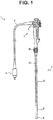
FIG. 1 illustrates a configuration of an endoscope. -
FIG. 2 illustrates configurations of a flexible tube portion and a rigidity changing mechanism portion. - Hereinafter, preferred embodiments of the present invention will be described with reference to drawings. Note that, in the drawings used for the description below, a different scale size is used for each of the components in order to allow each of the components to be illustrated in a recognizable size in the drawings, and the present invention is not limited to the number, shapes, ratio of the sizes of the components, and a relative positional relationship among the components shown in these drawings.
- An
endoscope 1 according to the present embodiment as shown inFIG. 1 includes anelongated insertion portion 2 configured to be introduceable into a subject such as a human body, and the endoscope includes, in theinsertion portion 2, a configuration for observing the inside of the subject. Note that the subject into which theinsertion portion 2 of theendoscope 1 is introduced is not limited to a human body, but may be another living body, or an artifact such as a machine, construction, and the like. - The
endoscope 1 according to the present embodiment is mainly configured by theinsertion portion 2 formed in an elongated shape so as to be introduced into a subject, anoperation portion 3 located at the proximal end of theinsertion portion 2, and a universal cord 4 extended from theoperation portion 3. - The
insertion portion 2 is configured by continuously including adistal end portion 8 disposed at the distal end of the insertion portion, a bendable bending portion 9 disposed at the proximal end side of thedistal end portion 8, and aflexible tube portion 10 having flexibility and configured to connect the proximal end side of the bending portion 9 and the distal end side of theoperation portion 3. - The
distal end portion 8 includes, for example, a configuration for observing an inside of a subject. For example, thedistal end portion 8 includes an image pickup unit including an objective lens and an image pickup device and configured to optically observe the inside of the subject. In addition, thedistal end portion 8 also includes an illumination light emitting portion that emits light for illuminating an object of the image pickup unit, though not shown. Note that thedistal end portion 8 may include an ultrasound transducer for sonically observing the inside of the subject by using ultrasound. - The
operation portion 3, which is disposed at the proximal end of theinsertion portion 2, is provided with anangle operating knob 6 for operating bending of the bending portion 9. At the proximal end portion of the universal cord 4, anendoscope connector 5 configured to be connectable to an external apparatus, not shown, is provided. The external apparatus to which theendoscope connector 5 is connected includes, for example, a camera control unit that controls the image pickup unit provided at thedistal end portion 8. - In addition, the
operation portion 3 is provided with arigidity changing knob 21 for operating a rigidity changingmechanism portion 20 disposed in theflexible tube portion 10. The rigidity changingmechanism portion 20 is inserted in theflexible tube portion 10 along the longitudinal direction of theflexible tube portion 10, and configured such that the rigidity against curve changes according to the operation input by means of therigidity changing knob 21. That is, the rigidity changingmechanism portion 20 changes the rigidity against curve of theflexible tube portion 10. - Next, description will be made on the configurations of the
flexible tube portion 10 and the rigidity changingmechanism portion 20. As shown inFIG. 2 , theflexible tube portion 10 includes amesh tube 11 and anouter cover 12. - The
mesh tube 11 is formed by braiding thin wires made of metal such as stainless alloy in a tubular shape. Theouter cover 12 is a film made of synthetic resin which covers the outer circumference of themesh tube 11. Themesh tube 11 is covered with theouter cover 12, to thereby maintain the airtightness in theflexible tube portion 10. In other words, themesh tube 11 is inserted in theflexible tube portion 10 having the cylindrical-shapedouter cover 12 on the outer circumference thereof. - Note that, inside the
mesh tube 11, a flex tube as a core member that prevents crushing of theflexible tube portion 10 is provided, though not shown. The flex tube is formed by spirally winding an elongated metallic thin plate around an axis along the longitudinal direction of theflexible tube portion 10. The width of the thin plate constituting the flex tube is narrower than a pitch width of the wound thin plate, the flex tube deforms in accordance with the curve of theflexible tube portion 10. - Inside the
flexible tube portion 10 configured as described above, in addition to the above-described rigidity changingmechanism portion 20, internal components such as an electric cable that electrically connects the image pickup unit and the endoscope connector, conduits through which fluid, a treatment instrument, etc., are passed are inserted. Since the internal components other than the rigidity changingmechanism portion 20 are known techniques, descriptions thereof will be omitted. - The rigidity changing
mechanism portion 20 includes acoil pipe 22, afirst wire 24, and asecond wire 26, which are linear members. With regard to the members constituting the rigidity changingmechanism portion 20, the direction toward thedistal end portion 8 of theinsertion portion 2 is referred to as a distal end direction and the direction toward theoperation portion 3 is referred to as a proximal end direction. - The
coil pipe 22 is a linear member formed by winding a linear element wire made of metal such as stainless alloy spirally around a predetermined axis A parallel to the longitudinal direction of theinsertion portion 2. - The diameter of the element wire constituting the
coil pipe 22 is larger than a maximum gap created between the thin wires adjacent to each other in themesh tube 11. In other words, the maximum dimension of the gap created in themesh tube 11 is smaller than the diameter of the element wire of thecoil pipe 22. - The
proximal end 22b of thecoil pipe 22 is held by acoil fixing portion 23 fixed to theoperation portion 3. Thecoil pipe 22 includes, inside thereof, a space having a predetermined inner diameter, with the predetermined axis A as a center. Thefirst wire 24 to be described later is inserted in thecoil pipe 22. - The
first wire 24 is a linear member inserted in thecoil pipe 22 and formed by intertwining linear element wires made of metal. Thefirst wire 24 is formed by intertwining the element wires made of stainless alloy, for example. - The diameter of the
first wire 24 is larger than the maximum gap created between the thin wires adjacent to each other in themesh tube 11. In other words, the maximum dimension of the gap created in themesh tube 11 is smaller than the diameter of thefirst wire 24. - The element wires of the
first wire 24 have a diameter smaller than that of the element wire constituting thecoil pipe 22. The rigidity of the element wires of thefirst wire 24 is lower than the rigidity of theouter cover 12, and the element wires of thefirst wire 24 have such a strength that the element wires do not pierce the surface of theouter cover 12. For example, even if the element wires of thefirst wire 24 are butted against theouter cover 12 from the direction perpendicular to theouter cover 12, thefirst wire 24 is buckle-deformed without piercing theouter cover 12. - A
distal end 24a of thefirst wire 24 inserted in thecoil pipe 22 is engaged with adistal end 22a of thecoil pipe 22 such that a force compressing thecoil pipe 22 along the axis A is applied to thecoil pipe 22 when thefirst wire 24 is pulled in the proximal end direction. - Specifically, the
distal end 24a of thefirst wire 24 protrudes in the distal end direction with respect to thedistal end 22a of thecoil pipe 22. A connectingportion 25 having an outer shape larger than the inner diameter of thecoil pipe 22 is secured at thedistal end 24a of thefirst wire 24. That is, the relative movement of thedistal end 24a of thefirst wire 24 in the proximal end direction with respect to thedistal end 22a of thecoil pipe 22 is restricted by the connectingportion 25. - In addition, the connecting
portion 25 is secured to thedistal end 22a of thecoil pipe 22 by adhesive, soldering, or brazing. That is, thedistal end 24a of thefirst wire 24 is fixed to thedistal end 22a of thecoil pipe 22. Note that thedistal end 24a of thefirst wire 24 may be directly secured to thedistal end 22a of thecoil pipe 22 by adhesive, soldering or brazing without using the connectingportion 25. - As described above, the
proximal end 22b of thecoil pipe 22 is fixed to theoperation portion 3 with acoil fixing portion 23. Therefore, when thefirst wire 24 is pulled in the proximal end direction, the tensile force applied to thefirst wire 24 is transmitted to thedistal end 22a of thecoil pipe 22, and the compression force in the direction of the axis A is applied to thecoil pipe 22. The compression force is applied to thecoil pipe 22, to thereby increase the resistance force of thecoil pipe 22 against bending deformation. The greater the compression force applied to thecoil pipe 22, the greater the resistance force of thecoil pipe 22 against bending deformation. - The
proximal end 24b of thefirst wire 24 is connected to the pullingmechanism portion 30 that pulls thefirst wire 24 in the proximal end direction to apply a tensile force to thefirst wire 24. - Since the pulling
mechanism portion 30 is known, detailed description thereof will be omitted. In the present embodiment, as one example, the pullingmechanism portion 30 includes arigidity changing knob 21 that rotates with respect to theoperation portion 3 and awire holding portion 30a that holds theproximal end 24b of thefirst wire 24 and advances and retracts in the direction along the axis A in accordance with the rotation of therigidity changing knob 21. - A
cam groove 21b is carved on the inner circumferential surface of therigidity changing knob 21. Thewire holding portion 30a is disposed in theoperation portion 3 so as to be able to advance and retract in the direction along the axis A. In addition, thewire holding portion 30a includes acam pin 30b that is slidably engaged with thecam groove 21b. The engagement between thecam groove 21b and thecam pin 30b causes thewire holding portion 30a to advance and retract in the direction along the axis A in accordance with the rotation of therigidity changing knob 21. The pullingmechanism portion 30 configured as described above in the present embodiment is capable of changing the tensile force to be applied to thefirst wire 24 in accordance with the rotation operation of therigidity changing knob 21 by a user. - The
second wire 26 is a linear member formed by intertwining the linear element wires made of metal. Thesecond wire 26 is formed by intertwining the element wires made of stainless alloy or the like, for example. - The diameter of the
second wire 26 is smaller than the diameter of thefirst wire 24, but larger than the maximum gap created between the thin wires adjacent to each other in themesh tube 11. In other words, the maximum dimension of the gap created in themesh tube 11 is smaller than the diameter of thesecond wire 26. - The element wires of the
second wire 26 have a diameter smaller than that of the element wires of thefirst wire 24. In addition, the element wires of thesecond wire 26 are made of a material having a tensile strength smaller than that of the element wires of thefirst wire 24. The diameter of thesecond wire 26 is smaller than that of thefirst wire 24. - The rigidity of the element wires of the
second wire 26 is lower than the rigidity of theouter cover 12, similarly as the element wires of thefirst wire 26, and the element wires of thesecond wire 26 have such a strength that the element wires do not pierce the surface of theouter cover 12. For example, even if the element wires of thesecond wire 26 are butted against theouter cover 12 from the direction perpendicular to the surface ofouter cover 12, thesecond wire 26 is buckle-deformed without piercing theouter cover 12. - The
second wire 26 is fixed to the constituent member of theinsertion portion 2 in the state where the rotation of thedistal end 26a is restricted, and theproximal end 26b is fixed to thedistal end 24a of thefirst wire 24. That is, thesecond wire 26 is arranged on the distal end side with respect to thefirst wire 24. - Specifically, the
distal end 26a of thesecond wire 26 is fixed to awire fixing portion 28 of abarrel member 9a arranged at the proximal end of the bending portion 9 of theinsertion portion 2 in the state where the rotation of thedistal end 26a around the axis A is restricted. Thedistal end 26a of thesecond wire 26 is secured to thewire fixing portion 28 by adhesive, soldering, brazing, or the like, for example. - In addition, the
proximal end 26b of thesecond wire 26 is secured to the connectingportion 25 by adhesive, soldering, brazing, or the like, for example. Thedistal end 24a of thefirst wire 24 and theproximal end 26b of thesecond wire 26 are secured respectively to the connectingportion 25 such that the central axes of the first and second wires are positioned on the axis A. - Note that the
proximal end 26b of thesecond wire 26 may be secured directly to thedistal end 24a of thefirst wire 24 by adhesive, soldering, brazing, or the like, for example, without using the connectingportion 25. - The
distal end 26a of thesecond wire 26 is secured to thebarrel member 9a of the bending portion 9, to thereby hold the position of thedistal end 24a of thefirst wire 24 in theflexible tube portion 10 within the predetermined range. That is, the movable range of thedistal end 22a of thecoil pipe 22 in theflexible tube portion 10 is determined by thesecond wire 26. Therefore, thecoil pipe 22 is held so as to be movable only within the range determined by thesecond wire 26, when thefirst wire 24 is pulled in the proximal end direction by the pullingmechanism portion 30, or when theflexible tube portion 10 is repeatedly curved. - As described above, the resistance force of the
coil pipe 22 against the bending deformation changes according to the tensile force applied to thefirst wire 24 by the pullingmechanism portion 30. Therefore, the rigidity of theflexible tube portion 10 against curve in the range in which thecoil pipe 22 is arranged changes according to the resistance force of thecoil pipe 22 against the bending deformation. With the above-described configuration, the rigidity changingmechanism portion 20 changes the rigidity of at least a part of theinsertion portion 2. - As described above, the rigidity changing
mechanism portion 20 in theendoscope 1 according to the present embodiment includes thecoil pipe 22, thefirst wire 24, and thesecond wire 26 that are linear members inserted in theflexible tube portion 10. In addition, theflexible tube portion 10 that encloses the circumferences of the linear members includes themesh tube 11 formed by braiding the thin wires in a tubular shape, and theouter cover 12 that covers the outer circumference of themesh tube 11. - In the present embodiment, the maximum dimension of the gap created between the thin wires adjacent to each other in the
mesh tube 11 is smaller than the diameter of the element wire of thecoil pipe 22. Therefore, even if thecoil pipe 22 is broken when theflexible tube portion 10 is curved to a bending radius smaller than the predetermined allowable bending radius in the state where thecoil pipe 22 is compressed by thefirst wire 24 being pulled by the pullingmechanism portion 30, for example, the element wire constituting thecoil pipe 22 does not protrude outside of themesh tube 11. Therefore, the present embodiment prevents the element wire of thecoil pipe 22 from contacting theouter cover 12 when thecoil pipe 22 is broken, to thereby be capable of preventing damage on theouter cover 12. - In addition, the maximum dimension of the gap created between the thin wires adjacent to each other in the
mesh tube 11 is smaller than the diameters of thefirst wire 24 and thesecond wire 26. Therefore, even if thefirst wire 24 or thesecond wire 26 are cut, thefirst wire 24 or thesecond wire 26 does not protrude outside themesh tube 11. The present embodiment prevents thefirst wire 24 or thesecond wirer 26 from contacting theouter cover 12 when thefirst wire 24 or thesecond wire 26 is cut, to thereby be capable of preventing the damage on theouter cover 12. - Since the diameters of the element wires constituting the
first wire 24 and thesecond wire 26 are smaller than the maximum dimension of the gap created between the thin wires adjacent to each other in themesh tube 11, when the cutfirst wire 24 orsecond wire 26 are loosened, there is a possibility that some of the element wires penetrate through themesh tube 11 to contact theouter cover 12. However, in the present embodiment, the rigidities of the element wires constituting thefirst wire 24 and thesecond wire 26 are lower than the rigidity of theouter cover 12. Therefore, even if the element wires themselves contact theouter cover 12, damage on theouter cover 12 is prevented. - As described above, with the
endoscope 1 according to the present embodiment, even in the case where thecoil pipe 22, thefirst wire 24, and thesecond wire 26, which are included in the rigidity changingmechanism portion 20 and are linear members inserted through theinsertion portion 2 are damaged, theouter cover 12 covering the outer circumference of theinsertion portion 2 is prevented from being damaged, which enables the watertightness of theinsertion portion 2 to be maintained. - Note that, as another embodiment, even if the rigidity of the element wires constituting the
first wire 24 is made higher than the rigidity of theouter cover 12, damage on theouter cover 12 can be prevented by making the diameter of each of the element wires of thefirst wire 24 smaller than the maximum dimension of the gap of thecoil pipe 22 and making the rigidity of the element wires constituting thesecond wire 26 lower than the rigidity of theouter cover 12. That is, the rigidities of the element wires of the wire and the coil that are exposed so as to face the inner surface of theflexible tube portion 10 are made lower than the rigidity of theouter cover 12, thereby enabling prevention of the damage on the outer cover, as the objective of the present invention. - In addition, the present invention is applicable not only to the linear members included in the rigidity changing
mechanism portion 20 but also to linear members such as other wires inserted in theinsertion portion 2. For example, as is known, bending operation wires for performing bending operation of the bending portion 9 are inserted in theinsertion portion 2, for example. The bending operation wires are pulled in accordance with the rotation of theangle operation knob 6, to cause the bending portion 9 to bend. When the present invention is applied to the bending operation wires, either the diameter of each of the bending operation wires or the diameter of each of the element wires of the bending operation wires is set to be larger than the maximum dimension of the gap created between the thin wires adjacent to each other in themesh tube 11. In addition, when the diameter of each of the element wires of the bending operation wires is smaller than the maximum dimension of the gap created between the thin wires adjacent to each other in themesh tube 11, the rigidity of the element wires is set to be lower than the rigidity of theouter cover 12. Also in this case, similarly as in the above-described embodiment, when the bending operation wires are cut, damage on theouter cover 12 covering the outer circumference of theinsertion portion 2 is prevented, to thereby be capable of maintaining the watertightness of theinsertion portion 2. - The present invention is not limited to the above-described embodiments, and various changes can be made, as needed, without departing from the gist or concept of the invention that can be read from claims and throughout the description. Endoscopes with such changes are also included in the technical range of the present invention.
- The present application claims priority from Japanese Patent Application No.
2015-227904
Claims (9)
- An endoscope comprising:an insertion portion formed in an elongated shape;a mesh tube formed by braiding thin wires in a tubular shape and provided in a shape of a cylinder inside the insertion portion; anda first linear member inserted in the insertion portion and formed by intertwining element wires,wherein a dimension of a gap created between the thin wires in the mesh tube is set to be smaller than a diameter of the first linear member and larger than a diameter of each of the element wires of the first linear member.
- The endoscope according to claim 1, further comprising,an outer cover made of resin and configured to cover an outer circumference of the mesh tube,wherein a rigidity of the element wires of the first linear member is set to be lower than a rigidity of the outer cover.
- The endoscope according to claim 1, wherein the linear member is a wire formed by intertwining the element wires.
- The endoscope according to claim 1, further comprising,a second linear member inserted in the insertion portion, and formed by winding an element wire,wherein the dimension of the gap created between the thin wires in the mesh tube is set to be smaller than a diameter of the second linear member and a diameter of the element wire of the second linear member.
- The endoscope according to claim 4, wherein the second linear member is a coil pipe formed by winding the element wire.
- The endoscope according to claim 1, wherein the first linear member is pulled by a pulling mechanism portion provided on a proximal end side of the insertion portion.
- The endoscope according to claim 5, wherein the first linear member is inserted in the second linear member.
- The endoscope according to claim 6, wherein the first linear member is pulled, to thereby cause a bending portion arranged on a distal end side of the insertion portion to bend.
- The endoscope according to claim 6, wherein the first linear member is pulled, to thereby change a rigidity of at least a part of the insertion portion.
Applications Claiming Priority (2)
| Application Number | Priority Date | Filing Date | Title |
|---|---|---|---|
| JP2015227904 | 2015-11-20 | ||
| PCT/JP2016/084050 WO2017086372A1 (en) | 2015-11-20 | 2016-11-17 | Endoscope |
Publications (1)
| Publication Number | Publication Date |
|---|---|
| EP3366189A1 true EP3366189A1 (en) | 2018-08-29 |
Family
ID=58719021
Family Applications (1)
| Application Number | Title | Priority Date | Filing Date |
|---|---|---|---|
| EP16866373.0A Withdrawn EP3366189A1 (en) | 2015-11-20 | 2016-11-17 | Endoscope |
Country Status (5)
| Country | Link |
|---|---|
| US (1) | US10799091B2 (en) |
| EP (1) | EP3366189A1 (en) |
| JP (1) | JP6223635B2 (en) |
| CN (1) | CN108348138A (en) |
| WO (1) | WO2017086372A1 (en) |
Families Citing this family (2)
| Publication number | Priority date | Publication date | Assignee | Title |
|---|---|---|---|---|
| WO2018207514A1 (en) * | 2017-05-10 | 2018-11-15 | オリンパス株式会社 | Endoscope |
| JP6402285B1 (en) * | 2017-05-10 | 2018-10-10 | オリンパス株式会社 | Endoscope |
Family Cites Families (11)
| Publication number | Priority date | Publication date | Assignee | Title |
|---|---|---|---|---|
| US5788714A (en) * | 1995-08-14 | 1998-08-04 | Asahi Kogaku Kogyo Kabushiki Kaisha | Flexible tube for an endoscope |
| JP3776557B2 (en) | 1997-04-10 | 2006-05-17 | オリンパス株式会社 | Endoscope |
| US6013047A (en) * | 1997-06-19 | 2000-01-11 | Hewlett-Packard Company | Method and apparatus for prevention of fluid intrusion in a probe shaft |
| JP3938624B2 (en) * | 1997-12-18 | 2007-06-27 | オリンパス株式会社 | Endoscope and endoscope hardness adjustment device |
| JP4061011B2 (en) * | 2000-06-30 | 2008-03-12 | オリンパス株式会社 | Endoscope |
| JP2002017658A (en) * | 2000-07-12 | 2002-01-22 | Olympus Optical Co Ltd | Endoscope |
| JP2006055664A (en) * | 2005-11-07 | 2006-03-02 | Olympus Corp | Endoscope |
| EP1958294A4 (en) * | 2005-11-23 | 2011-09-21 | Neoguide Systems Inc | Non-metallic, multi-strand control cable for steerable instruments |
| JP2007325748A (en) * | 2006-06-08 | 2007-12-20 | Pentax Corp | Endoscope |
| WO2011136115A1 (en) * | 2010-04-26 | 2011-11-03 | オリンパスメディカルシステムズ株式会社 | Endoscope |
| JP5917467B2 (en) | 2013-09-26 | 2016-05-18 | 富士フイルム株式会社 | Endoscope |
-
2016
- 2016-11-17 CN CN201680066336.5A patent/CN108348138A/en active Pending
- 2016-11-17 JP JP2017519952A patent/JP6223635B2/en active Active
- 2016-11-17 WO PCT/JP2016/084050 patent/WO2017086372A1/en not_active Ceased
- 2016-11-17 EP EP16866373.0A patent/EP3366189A1/en not_active Withdrawn
-
2018
- 2018-05-14 US US15/978,256 patent/US10799091B2/en active Active
Also Published As
| Publication number | Publication date |
|---|---|
| JP6223635B2 (en) | 2017-11-01 |
| US10799091B2 (en) | 2020-10-13 |
| CN108348138A (en) | 2018-07-31 |
| JPWO2017086372A1 (en) | 2017-11-24 |
| WO2017086372A1 (en) | 2017-05-26 |
| US20180256010A1 (en) | 2018-09-13 |
Similar Documents
| Publication | Publication Date | Title |
|---|---|---|
| CN103764012B (en) | Curved tubes, medical equipment | |
| JP5228161B2 (en) | Endoscope bending device | |
| EP3269292A1 (en) | Endoscope | |
| US20160007832A1 (en) | Endoscope | |
| JP6261835B1 (en) | Endoscope flexible tube | |
| JP5964880B2 (en) | Endoscope | |
| EP3135182A1 (en) | Endoscope bending section and endoscope | |
| EP3087898A1 (en) | Endoscope | |
| US20190099061A1 (en) | Endoscope | |
| US10799091B2 (en) | Endoscope with mesh tube | |
| EP2721991B1 (en) | Endoscope | |
| JP6689589B2 (en) | Endoscope | |
| US20240172927A1 (en) | Bending portion of endoscope, endoscope, and manufacturing method of bending portion of endoscope | |
| JP6402285B1 (en) | Endoscope | |
| US10213092B2 (en) | Sheath assembly, manipulator, and manipulator system | |
| WO2018207514A1 (en) | Endoscope | |
| JP6600485B2 (en) | Endoscope device | |
| JP2011200357A (en) | Endoscope | |
| JP2016214282A (en) | Endoscope device | |
| JPH08146305A (en) | Endoscope |
Legal Events
| Date | Code | Title | Description |
|---|---|---|---|
| STAA | Information on the status of an ep patent application or granted ep patent |
Free format text: STATUS: THE INTERNATIONAL PUBLICATION HAS BEEN MADE |
|
| PUAI | Public reference made under article 153(3) epc to a published international application that has entered the european phase |
Free format text: ORIGINAL CODE: 0009012 |
|
| STAA | Information on the status of an ep patent application or granted ep patent |
Free format text: STATUS: REQUEST FOR EXAMINATION WAS MADE |
|
| 17P | Request for examination filed |
Effective date: 20180514 |
|
| AK | Designated contracting states |
Kind code of ref document: A1 Designated state(s): AL AT BE BG CH CY CZ DE DK EE ES FI FR GB GR HR HU IE IS IT LI LT LU LV MC MK MT NL NO PL PT RO RS SE SI SK SM TR |
|
| AX | Request for extension of the european patent |
Extension state: BA ME |
|
| DAV | Request for validation of the european patent (deleted) | ||
| DAX | Request for extension of the european patent (deleted) | ||
| STAA | Information on the status of an ep patent application or granted ep patent |
Free format text: STATUS: THE APPLICATION IS DEEMED TO BE WITHDRAWN |
|
| 18D | Application deemed to be withdrawn |
Effective date: 20190601 |