EP3366177A1 - Device for supporting kitchen objects - Google Patents
Device for supporting kitchen objects Download PDFInfo
- Publication number
- EP3366177A1 EP3366177A1 EP18157713.1A EP18157713A EP3366177A1 EP 3366177 A1 EP3366177 A1 EP 3366177A1 EP 18157713 A EP18157713 A EP 18157713A EP 3366177 A1 EP3366177 A1 EP 3366177A1
- Authority
- EP
- European Patent Office
- Prior art keywords
- magnet
- magnets
- supporting
- kitchen
- objects
- Prior art date
- Legal status (The legal status is an assumption and is not a legal conclusion. Google has not performed a legal analysis and makes no representation as to the accuracy of the status listed.)
- Granted
Links
Images


Classifications
-
- A—HUMAN NECESSITIES
- A47—FURNITURE; DOMESTIC ARTICLES OR APPLIANCES; COFFEE MILLS; SPICE MILLS; SUCTION CLEANERS IN GENERAL
- A47J—KITCHEN EQUIPMENT; COFFEE MILLS; SPICE MILLS; APPARATUS FOR MAKING BEVERAGES
- A47J45/00—Devices for fastening or gripping kitchen utensils or crockery
- A47J45/02—Devices for fastening or gripping kitchen utensils or crockery for fastening kitchen utensils to tables, walls, or the like
-
- A—HUMAN NECESSITIES
- A47—FURNITURE; DOMESTIC ARTICLES OR APPLIANCES; COFFEE MILLS; SPICE MILLS; SUCTION CLEANERS IN GENERAL
- A47J—KITCHEN EQUIPMENT; COFFEE MILLS; SPICE MILLS; APPARATUS FOR MAKING BEVERAGES
- A47J47/00—Kitchen containers, stands or the like, not provided for in other groups of this subclass; Cutting-boards, e.g. for bread
- A47J47/16—Stands, or holders for kitchen articles
-
- A—HUMAN NECESSITIES
- A47—FURNITURE; DOMESTIC ARTICLES OR APPLIANCES; COFFEE MILLS; SPICE MILLS; SUCTION CLEANERS IN GENERAL
- A47K—SANITARY EQUIPMENT; ACCESSORIES THEREFOR, e.g. TOILET ACCESSORIES
- A47K10/00—Body-drying implements; Toilet paper; Holders therefor
- A47K10/12—Grips, hooks, or the like for hanging-up towels
-
- A—HUMAN NECESSITIES
- A47—FURNITURE; DOMESTIC ARTICLES OR APPLIANCES; COFFEE MILLS; SPICE MILLS; SUCTION CLEANERS IN GENERAL
- A47J—KITCHEN EQUIPMENT; COFFEE MILLS; SPICE MILLS; APPARATUS FOR MAKING BEVERAGES
- A47J36/00—Parts, details or accessories of cooking-vessels
- A47J36/34—Supports for cooking-vessels
-
- A—HUMAN NECESSITIES
- A47—FURNITURE; DOMESTIC ARTICLES OR APPLIANCES; COFFEE MILLS; SPICE MILLS; SUCTION CLEANERS IN GENERAL
- A47K—SANITARY EQUIPMENT; ACCESSORIES THEREFOR, e.g. TOILET ACCESSORIES
- A47K2201/00—Details of connections of bathroom accessories, e.g. fixing soap or towel holder to a wall
- A47K2201/02—Connections to a wall mounted support
Definitions
- the present invention refers to the field of kitchen accessories.
- the present invention deals with those kitchen accessories suitable for supporting other kitchen objects, in order to make them more immediately accessible and more conveniently usable.
- a plurality of devices are known in the art to enable the most used objects in the kitchen to be kept at hand and in plain sight, moreover without creating disorder.
- Some classic examples are hooks suitable to be fixed to walls or to furniture by means of screws, glue, adhesives, or also by means of suction cups, suitable to be fixed on plastic or tiled surfaces.
- the objects that are usually desirable to have at hand can be kitchen objects and various accessories, but in particular those that are mostly used in the kitchen at all times are sponges and dishcloths; to keep these devices at hand to make them easy to use or to put them away, certainly to hang or place in view them is one of the most practical solutions, because sponges and dishcloths are often damp by use, so leaving them in sight makes it easier to dry them in ambient air.
- suction cup hooks do not damage the surfaces, but are not suitable to be attached on every surface and often tend to detach due to moisture, thus providing poor reliability.
- hooks generally necessitate the use of objects with special slots suitable to be attached thereon.
- hooks, storage boxes or sponge holders etc. may not be visually pleasing or may not be appreciated by users.
- patent documents are known in the art which describe means dedicated to cleaning sponges, such as for example WO2007/144450 , which basically describes magnetic devices fixing sponges or similar objects to the kitchen sink; this device includes at least two magnets, one of which is located inside the sink tub and one outside the sink tub against the external structure of the sink.
- the outer magnet can be attached in a variety of ways and is designed to support the sponge or a similar object inside the sink.
- the patent application WO2008058546A1 describes a device which includes means suitable for attaching a dishcloth to various pieces of furniture: such device is composed of at least two magnets to be placed on the inside of a piece of furniture and by two additional magnets to be placed on the outside of that piece of furniture in correspondence with said first at least two magnets; moreover, an additional magnetic element of longitudinal shape is included, the two ends of which are suitable for attaching themselves to the magnets inside the piece of furniture.
- the device includes a foldable or not foldable rod to support a dishcloth.
- This device falls more within the scope of the known art of interest for the present invention but, as it is evident, disadvantageously, it includes a plurality of pieces that make it complex to assemble and use. Moreover it makes also necessary to have sufficient space to be able to fix the magnets in the furniture piece at the correct distance so that additional magnets can be applied on the outside and the metallic fixing bar for the dishcloths.
- said device can be inconvenient for the user because it is cumbersome and can prevent for example the correct opening of a door, and again, if it is positioned for example in the lower part of the kitchen furniture, the user could frequently bump into the rod protruding from the door, causing obvious discomfort to those in the kitchen, or the rod itself could detach from the support and fall to the ground with obvious inconvenience.
- WO 96/13191 describes a support strip provided with an elongated metal strip inside the support strip. Holes are provided in the support strip to hold corresponding magnets that attach themselves to the elongated metal strip.
- Kitchen cloth apparel such as pot holders, are especially made by two pieces of cloth sewn together inside which a ferromagnetic chain is provided, in order to allow magnetic attachment of the pot holder to the magnets of the support strip.
- US 5,895,018 describes a support system for magnetically supporting a thin, pliable section of material such as a kitchen towel from a surface.
- the support system includes a first plate with an upper surface and a lower surface and a second plate with an upper surface and a lower surface. Inside each of the two portions of the device, two magnets are provided inside each of the two portions of the device. The kitchen towel is supported between the two magnets and the device has to be attached magnetically to a magnetic or ferromagnetic surface.
- a purpose of the present invention is therefore to describe a device suitable to support kitchen objects that is versatile in its use and in its positioning.
- a further aim of the present invention is to describe a device suitable for supporting kitchen objects that is economical to produce and therefore easy to sell.
- a further aim of this invention is to describe a device suitable for supporting kitchen objects that is simple to use.
- Another further aim of this invention is to describe a device suitable for supporting kitchen objects that is unobtrusive and not bulky.
- a further aim of this invention is to describe a device suitable for supporting kitchen objects that improves access to such objects.
- a further purpose of this invention is to describe a device that can be assembled in a variety of ways.
- the innovative device suitable for supporting kitchen objects described by the present invention comprising a device suitable for supporting kitchen objects, comprising at least a first supporting magnet suitable for being fixed on at least a surface and a second magnet adapted to be coupled on a first side to said at least one first supporting magnet by means of specially calibrated magnetic force, said at least one first supporting magnet being fixed on a surface and exerting its magnetic force through the thickness of said surface, the magnetic force being suitable to hold said at least one second magnet through the surface, said at least one second magnet comprising means adapted to support kitchen objects, said at least one second magnet being adapted to retain, in cooperation with said supporting magnet, at least one or more kitchen objects.
- the device comprises at least a first supporting magnet suitable for being fixed on at least a surface and a second magnet adapted to be coupled on a first side to said at least one first magnet by means of specially calibrated magnetic force, in a particularly advantageous way said at least one first magnet is housed inside of a door of a furniture or the like, visible or not visible from the outside, exerting magnetic force suitable to hold said at least one second magnet through the surface S, said at least one second magnet may comprise means adapted to support kitchen objects, and/or may further be suitable to be coupled on a second side to at least a third magnet, said at least one second magnet being adapted to retain within, between said couple of magnets at least one kitchen object, said at least one or a couple of magnets being bound to said supporting magnet.
- said at least a second and a third magnet are suitable for accommodating between them at least one or more kitchen object, in such a way as to be fixed by coupling with said at least one first supporting magnet at least one kitchen object to the furniture piece to which said at least one first magnet is fixed and possibly fixing one or more other kitchen means between pairs of magnets or to single magnets, each of these magnets being suitable to be held in place by said first supporting magnet.
- the at least two or three magnets which in the description of the attached figures will be called M1, M2, M3, will be dimensioned in such a way that the force of M1 is properly calibrated in order to be able to support the weight of the kitchen object that will be fixed to M1 being held by M2, and or M2/M3, and in a further advantageous way M1 will be dimensioned in such a way that its force of attraction with respect to M2 and/or M3 will be lower than the force of attraction between M2 and M3; this in order that by pulling the kitchen object, it detaches from M1, carrying with it M2 and M3 always mutually connected.
- these magnets are suitable to mutually attach and retain a plurality of kitchen objects, such as for example dishcloths, aprons, pot holders, kitchen gloves or various accessories, provided that they are of suitable dimensions and have characteristics suitable to be supported in this way.
- kitchen objects such as for example dishcloths, aprons, pot holders, kitchen gloves or various accessories.
- the magnets may be of any size desired, provided that they are suitable for the purpose described by the present invention; moreover, the shape of the magnets may also be of any type, round, square, stylized in the shape of any object, flower, animal, etc..
- the magnetic power, or magnetic field strength of the magnets will be calibrated according to the shape of the device chosen, and/or will be calibrated to attach objects with different weight and characteristics and/or shape.
- this innovative device for supporting kitchen objects can include, connected to these magnets, or realized as magnetic elements M1,.... Mn, means such as hooks, clips, clasps, made as attachments or made of magnetic material themselves, or magnets with rings or other fastening elements, for example for kitchen tools having an eyelet or similar.
- the surface to which the first supporting magnet and the second magnet are fixed is non-magnetic or non-ferromagnetic.
- a pair of magnets M2, M3 is hereby represented, for example having circular flat shape; the two magnets can be made advantageously of any shape or color, or be covered with decorative elements etc..
- Said pair of magnets M2, M3 is obviously suitable to reciprocally attract and the attraction force between them will be calibrated in such a way as to be sufficient to hold a kitchen object C, such as a dishcloth, between said two magnets as visible in fig. 2b .
- the two magnets M2 and M3 are extremely practical to be applied and to be removed and they remain in their seat during use of the cloth, without in any way hindering or limiting the practicality of use thereof.
- Figs. 2a and 2b show the device 1 for supporting kitchen objects, which can also be considered a kit for supporting kitchen objects, complete in its parts in a particularly preferred basic form of realization.
- a supporting magnet M1 fixed, for example, by gluing, or by other suitable method, to a surface S such as a door of a kitchen cabinet.
- Said supporting magnet M1 in the present form of realization has a circular shape with two flat faces, but it may have any other shape suitable for the purpose.
- the size, namely the magnetic attraction surface SM of the magnet M1 will be calibrated to support one or more magnets, or one or more pairs of magnets M2, M3 in such a way that by detaching the kitchen object C supported between the pair of magnets M2, M3, the pair of magnets M2, M3 remains connected to each other and is disconnected from the supporting magnet M1.
- the magnet M1 exerts its magnetic attraction force through the thickness S' of the surface S, therefore the magnetic force will be calibrated also to have the correct effect (as specified above) also in this sense.
- the supporting magnet M1 by virtue of special fixing means, is suitable to be fixed on any surface and in a further advantageous way it does not alter the aesthetics, for example of the furniture piece on which it is applied as it remains completely concealed, for example inside the door of said furniture piece.
- the one or more supporting magnets M1 can be attached directly, for example, to a door or surface suitable for this purpose or can be housed within suitable supports adapted, for example to be screwed or glued to a suitable surface.
- a supporting magnet M1 In particular, in fig. 2c it is represented a supporting magnet M1, and two additional secondary magnets M2, M3 connected to each other supporting a kitchen means C such as a dishcloth or pot holder or similar.
- a kitchen means C such as a dishcloth or pot holder or similar.
- at least one further pair of magnets M4, M5 will be connected to the magnet M3, which in turn will be suitable to support one another a kitchen means C' equal or different to said first means C.
- any number of objects can be connected in the same way defined for example as “castled” or stacked, obviously within the limit of the weight of the objects to be supported and of the magnetic attraction capacity exerted by M1 and by further Mn magnets capable of exerting in turn a magnetic force in the form of magnetic chain.
- Mn+1 a magnet
- Mn that is by the magnets connected between Mn+1 and M1.
- similarly further pairs of magnets Mn, Mn+1, etc. can be fixed and maintained connected to a surface S on which, or behind which, at least one supporting magnet M1 is positioned, one next to the other, depending on the magnetic attraction force exerted by M1 or in relation to the structure of the magnetic field; this allows a possible adhesion of magnets or pairs of magnets even beyond the physical boundaries corresponding to the surface of the magnet SM which is in contact with the surface S of the piece of furniture or similar element.
- pairs of magnets M2, M3 and/or M4, M5, and/or Mn, Mn+1 can always be replaced with single magnets comprising means suitable for supporting kitchen objects, such as clips, clasps, hooks, eyelets, rings or other objects suitable for this purpose; or moreover a magnet of the pair may include suitable means to support an additional kitchen object, in this variant a kitchen object will be supported for example by two magnets Mn1, Mn2 and at least one, or each of these magnets may include one or more means, such as hooks, pliers, carabiners, eyelets, etc.. suitable to support an additional kitchen object.
- this device is composable in infinite ways and providing versatility and originality to this innovative device to support objects for kitchen or "kit”.
- Figure 3a and 3b show two operational views of the use of a basic design form of the kit for supporting kitchen objects or a device to support kitchen objects object of the present invention, applied for example to a dishcloth; note that one or more supporting magnets M1 can also be placed in cavities of kitchen furniture, wall units, drawers, coffers, etc..
- the object of the present invention is therefore suitable to fulfill all the purposes described above, providing considerable advantages in terms of practicality and versatility in the field, including as fundamental: insufficient or minimal overall dimensions, concealed positioning in furniture, wall units or similar, no impact on the aesthetics of the furniture or of the environment itself, versatility in the composition of the various parts of the kit or device, as well as use for various objects among which we cite only by way of example aprons, flaps, pot holders, dishcloths, ladles or similar objects etc..
- this device has been defined advantageously as particularly suitable for supporting kitchen objects, but it could be suitable for other types of objects and basically for every room in a house or similar environment (school, hotel, restaurant, bar, etc.).
- said innovative, customizable and modular kit or device for supporting objects allows to solve all the mentioned problems of the known art, variations in the form of the supporting or secondary magnets, number of assembled magnets, fixing mode of the one or more the main magnets to one or to a plurality of surfaces, the number of the magnets used or the method of connection between magnets or between elements suitable to be used with said kit or device for supporting kitchen objects should be considered included in the object of the present invention as better defined by the annexed claims.
Landscapes
- Engineering & Computer Science (AREA)
- Food Science & Technology (AREA)
- Health & Medical Sciences (AREA)
- Public Health (AREA)
- Supports Or Holders For Household Use (AREA)
- Combinations Of Kitchen Furniture (AREA)
Abstract
Description
- The present invention refers to the field of kitchen accessories. In particular, the present invention deals with those kitchen accessories suitable for supporting other kitchen objects, in order to make them more immediately accessible and more conveniently usable.
- A plurality of devices are known in the art to enable the most used objects in the kitchen to be kept at hand and in plain sight, moreover without creating disorder.
- Some classic examples are hooks suitable to be fixed to walls or to furniture by means of screws, glue, adhesives, or also by means of suction cups, suitable to be fixed on plastic or tiled surfaces. The objects that are usually desirable to have at hand can be kitchen objects and various accessories, but in particular those that are mostly used in the kitchen at all times are sponges and dishcloths; to keep these devices at hand to make them easy to use or to put them away, certainly to hang or place in view them is one of the most practical solutions, because sponges and dishcloths are often damp by use, so leaving them in sight makes it easier to dry them in ambient air.
- The advantage of hooks, wall-mounted containers, and so on is obvious, one of the equally obvious disadvantages is the fact that fixing a hook to a wall involves drilling it, or gluing onto tiles/walls/surfaces, operations which can damage the surfaces themselves; moreover once fixed, the positioning of the object always in the same place becomes mandatory.
- Conversely suction cup hooks do not damage the surfaces, but are not suitable to be attached on every surface and often tend to detach due to moisture, thus providing poor reliability. In addition, hooks generally necessitate the use of objects with special slots suitable to be attached thereon.
- Moreover, hooks, storage boxes or sponge holders etc., may not be visually pleasing or may not be appreciated by users.
- In particular, there is a substantial difference between means of supporting objects such as sponges and similar objects, which are in particular used in the sink and constantly wet or humid, and dishcloths, ladles or similar.
- In this regard, patent documents are known in the art which describe means dedicated to cleaning sponges, such as for example
WO2007/144450 , which basically describes magnetic devices fixing sponges or similar objects to the kitchen sink; this device includes at least two magnets, one of which is located inside the sink tub and one outside the sink tub against the external structure of the sink. The outer magnet can be attached in a variety of ways and is designed to support the sponge or a similar object inside the sink. - Also, similarly, document
US911585484B2 which describes a magnetic accessory suitable to be attached to a ferromagnetic or non ferromagnetic kitchen sink. If the sink is not ferromagnetic, it would appear that a magnetic accessory fixed to the outside of the sink may be present. This device is suitable for attaching objects such as sponge holders etc. on the inside of the sink and is equipped with a magnetic decomposable device suitable to be fixed on means such as a soap holder, a cup, a small shelf etc.. Likewise, there are a number of documents describing more or less creative means to fix, in the sink itself, sponges or means suitable for use in the sink. - These devices in particular are not of interest for the purpose of this invention, which includes among its purposes the description of a device suitable for supporting kitchen accessories such as dishcloths or kitchen accessories, which are not suitable to be housed inside the sink, so that the solutions adopted for this purpose must necessarily be different, in fact the dishcloths or kitchen accessories usually have to be housed in such a way that they are not wet if not when desired and often have dimensions that make them unsuitable for being housed in cramped spaces such as a kitchen sink.
- Furthermore, the materials used in such patent applications substantially exploit the ferromagnetic characteristics of the sink, a fundamental feature of these documents but that is not relevant for the purpose of the present invention.
- The patent application
WO2008058546A1 describes a device which includes means suitable for attaching a dishcloth to various pieces of furniture: such device is composed of at least two magnets to be placed on the inside of a piece of furniture and by two additional magnets to be placed on the outside of that piece of furniture in correspondence with said first at least two magnets; moreover, an additional magnetic element of longitudinal shape is included, the two ends of which are suitable for attaching themselves to the magnets inside the piece of furniture. The device includes a foldable or not foldable rod to support a dishcloth. - This device falls more within the scope of the known art of interest for the present invention but, as it is evident, disadvantageously, it includes a plurality of pieces that make it complex to assemble and use. Moreover it makes also necessary to have sufficient space to be able to fix the magnets in the furniture piece at the correct distance so that additional magnets can be applied on the outside and the metallic fixing bar for the dishcloths.
- Moreover, said device can be inconvenient for the user because it is cumbersome and can prevent for example the correct opening of a door, and again, if it is positioned for example in the lower part of the kitchen furniture, the user could frequently bump into the rod protruding from the door, causing obvious discomfort to those in the kitchen, or the rod itself could detach from the support and fall to the ground with obvious inconvenience.
- Also, from the point of view of practicality, it is not a convenient or versatile object to adapt to spaces and environments and it is not clear whether it is easily removable or not from a surface.
- Moreover, this device immediately appears to an expert in the field to be quite expensive to produce, given the multiplicity of different elements that compose it.
-
WO 96/13191 -
US 5,895,018 describes a support system for magnetically supporting a thin, pliable section of material such as a kitchen towel from a surface. The support system includes a first plate with an upper surface and a lower surface and a second plate with an upper surface and a lower surface. Inside each of the two portions of the device, two magnets are provided. The kitchen towel is supported between the two magnets and the device has to be attached magnetically to a magnetic or ferromagnetic surface. - A purpose of the present invention is therefore to describe a device suitable to support kitchen objects that is versatile in its use and in its positioning.
- A further aim of the present invention is to describe a device suitable for supporting kitchen objects that is economical to produce and therefore easy to sell.
- A further aim of this invention is to describe a device suitable for supporting kitchen objects that is simple to use.
- Another further aim of this invention is to describe a device suitable for supporting kitchen objects that is unobtrusive and not bulky.
- It is a further aim of the present invention to describe a device suitable for supporting kitchen objects that is versatile and adaptable to multiple objects.
- A further aim of this invention is to describe a device suitable for supporting kitchen objects that improves access to such objects.
- It is also a further purpose of this invention to describe a device suitable for supporting kitchen objects that is suitable to be housed anywhere in the kitchen without hindering the user's movements or preventing access to furniture or hindering the opening or closing thereof.
- A further purpose of this invention is to describe a device that can be assembled in a variety of ways.
- Finally, it is a purpose of the present invention to describe a device suitable to support kitchen objects that constitute a valid and attractive alternative to common hooks or similar.
- These and other aims will be realized by virtue of the innovative device suitable for supporting kitchen objects described by the present invention comprising a device suitable for supporting kitchen objects, comprising at least a first supporting magnet suitable for being fixed on at least a surface and a second magnet adapted to be coupled on a first side to said at least one first supporting magnet by means of specially calibrated magnetic force, said at least one first supporting magnet being fixed on a surface and exerting its magnetic force through the thickness of said surface, the magnetic force being suitable to hold said at least one second magnet through the surface, said at least one second magnet comprising means adapted to support kitchen objects, said at least one second magnet being adapted to retain, in cooperation with said supporting magnet, at least one or more kitchen objects.
- According to an embodiment of the invention, the device comprises at least a first supporting magnet suitable for being fixed on at least a surface and a second magnet adapted to be coupled on a first side to said at least one first magnet by means of specially calibrated magnetic force, in a particularly advantageous way said at least one first magnet is housed inside of a door of a furniture or the like, visible or not visible from the outside, exerting magnetic force suitable to hold said at least one second magnet through the surface S, said at least one second magnet may comprise means adapted to support kitchen objects, and/or may further be suitable to be coupled on a second side to at least a third magnet, said at least one second magnet being adapted to retain within, between said couple of magnets at least one kitchen object, said at least one or a couple of magnets being bound to said supporting magnet.
- Still further advantageously, said at least a second and a third magnet are suitable for accommodating between them at least one or more kitchen object, in such a way as to be fixed by coupling with said at least one first supporting magnet at least one kitchen object to the furniture piece to which said at least one first magnet is fixed and possibly fixing one or more other kitchen means between pairs of magnets or to single magnets, each of these magnets being suitable to be held in place by said first supporting magnet. It should be noted that, in a particularly advantageous way, the at least two or three magnets, which in the description of the attached figures will be called M1, M2, M3, will be dimensioned in such a way that the force of M1 is properly calibrated in order to be able to support the weight of the kitchen object that will be fixed to M1 being held by M2, and or M2/M3, and in a further advantageous way M1 will be dimensioned in such a way that its force of attraction with respect to M2 and/or M3 will be lower than the force of attraction between M2 and M3; this in order that by pulling the kitchen object, it detaches from M1, carrying with it M2 and M3 always mutually connected.
- Further variants will be described in the attached figures.
- In a further advantageous way, these magnets are suitable to mutually attach and retain a plurality of kitchen objects, such as for example dishcloths, aprons, pot holders, kitchen gloves or various accessories, provided that they are of suitable dimensions and have characteristics suitable to be supported in this way. There are no restrictions on the type of object to be used with the device object of the present invention, the choice remains totally up to the user and obviously will be limited only by the weight of the object, by the possible encumbrance thereof and as said by having the characteristics that make the object suitable to be bound with at least two magnets (including the supporting magnet) or with several magnets of such kind.
- In a further advantageous way, it will obviously be possible to use these devices coupled together, or it will be possible to put a device or a plurality of devices in a chosen place, to attach one or more objects with one or more devices to support objects, particularly kitchen objects, described by the present invention.
- Still, in an advantageous way it will be possible in some forms of realization to attach to said at least a first M1 magnet, one, a pair or a plurality of magnets M2... Mn, Mn+1, suitable for supporting one or more objects, such as one or more kitchen cloths, said magnets or pairs of magnets M2... Mn being all bound to said first magnet M1, or attached to one another.
- It should be noted that, in a particularly advantageous way, the magnets may be of any size desired, provided that they are suitable for the purpose described by the present invention; moreover, the shape of the magnets may also be of any type, round, square, stylized in the shape of any object, flower, animal, etc..
- Moreover, also the magnetic power, or magnetic field strength of the magnets will be calibrated according to the shape of the device chosen, and/or will be calibrated to attach objects with different weight and characteristics and/or shape.
- Moreover, in a further advantageous way, this innovative device for supporting kitchen objects can include, connected to these magnets, or realized as magnetic elements M1,.... Mn, means such as hooks, clips, clasps, made as attachments or made of magnetic material themselves, or magnets with rings or other fastening elements, for example for kitchen tools having an eyelet or similar.
- It should be noted that, in a particularly advantageous way, it will not be necessary to fix hooks or other objects to mobile walls or tiles, for the benefit of practicality and also of the aesthetics of the environment, also, there will be no bars or similar objects to support such objects, which as mentioned above may be cumbersome and impractical. Preferably, the surface to which the first supporting magnet and the second magnet are fixed is non-magnetic or non-ferromagnetic.
- Finally, it will be possible, for example, to attach by means of this innovative device any dishcloth with or without eyelets, in an extremely quick and practical way.
- These and other advantages obtained thanks to the innovative device for supporting objects in particular for kitchen objects described by the present invention will be further examined and clarified by the description of the attached figures in which:
- in
fig. 1a, 1b it is represented a basic form of realization of a part of the device for supporting kitchen objects described by the present invention; - in
fig. 2a, 2b it is represented the same form of realization offig. 1a, 1b in the completeness of the innovative device described here in two operating phases; - in
fig. 2c it is represented a different form of realization of the device suitable for supporting kitchen objects described by the present invention:- in
fig. 3a, 3b are represented examples of phases of actual use of the innovative device that is an object of the invention.
- in
- With reference to
figures 1a and 1b , it is represented a particularly preferred form of realization of a part of theinnovative device 1 for supporting objects in particular kitchen objects described by the present invention. In particular, a pair of magnets M2, M3 is hereby represented, for example having circular flat shape; the two magnets can be made advantageously of any shape or color, or be covered with decorative elements etc.. Said pair of magnets M2, M3 is obviously suitable to reciprocally attract and the attraction force between them will be calibrated in such a way as to be sufficient to hold a kitchen object C, such as a dishcloth, between said two magnets as visible infig. 2b . - It should be noted that, in a particularly advantageously way, the two magnets M2 and M3 are extremely practical to be applied and to be removed and they remain in their seat during use of the cloth, without in any way hindering or limiting the practicality of use thereof. As anticipated, it will therefore not be necessary to equip oneself with cloths having holes or eyelets; further said magnets in this or in other forms of realization may be used with a plurality of kitchen objects suitable to be hung, this obviously provided that the chosen form of realization is suitable for the object to be supported.
-
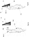
Figs. 2a and 2b show thedevice 1 for supporting kitchen objects, which can also be considered a kit for supporting kitchen objects, complete in its parts in a particularly preferred basic form of realization. - In particular, in
fig. 2a it is visible a supporting magnet M1 fixed, for example, by gluing, or by other suitable method, to a surface S such as a door of a kitchen cabinet. Said supporting magnet M1 in the present form of realization has a circular shape with two flat faces, but it may have any other shape suitable for the purpose. The size, namely the magnetic attraction surface SM of the magnet M1 will be calibrated to support one or more magnets, or one or more pairs of magnets M2, M3 in such a way that by detaching the kitchen object C supported between the pair of magnets M2, M3, the pair of magnets M2, M3 remains connected to each other and is disconnected from the supporting magnet M1. Infigures 2a, 2b it is represented the position of the object C connected to said pair of magnets M2, M3 but released from M1 and the rest position in which the object is supported, for example hanging from a door of a furniture piece to which the supporting magnet M1 is firmly attached. - It is to be noted that the magnet M1 exerts its magnetic attraction force through the thickness S' of the surface S, therefore the magnetic force will be calibrated also to have the correct effect (as specified above) also in this sense.
- In a particularly advantageous way, the supporting magnet M1, by virtue of special fixing means, is suitable to be fixed on any surface and in a further advantageous way it does not alter the aesthetics, for example of the furniture piece on which it is applied as it remains completely concealed, for example inside the door of said furniture piece.
- The one or more supporting magnets M1 (..... M1n) can be attached directly, for example, to a door or surface suitable for this purpose or can be housed within suitable supports adapted, for example to be screwed or glued to a suitable surface.
- It is to be noted that when approaching the kitchen object attached or bound to two magnets - or in a different form of realization to a single magnet - to the piece of furniture area where at least one supporting magnet M1 is fixed, the object will be attracted by the magnetic force exerted by the magnet M1 on at least one magnet M2 in place, without the need for external recognition marks on the piece of furniture; this is particularly advantageous for the aesthetics of the furniture that remains unaltered and also practically advantageously, because uncomfortable hooks, rods or further elements that may interfere with a user o limit the opening for example of a door are not present In any case, at the user's choice, it will be possible to place a sticker or similar element near the magnetic attraction zone of the supporting magnet M1 in order to facilitate the identification of the fixing zone.
- In
fig. 2a and 2b are represented as mentioned above two operational positions of use of said device or kit of support for kitchen objects, infigure 2c is also represented an example of one of the many possible forms of realization of the present invention, noting that the addition of elements such as magnets to the same device substantially in unlimited ways that makes it versatile and assemblable at the user's will, makes the definition of "kit" to support, hold or sustain kitchen objects particularly effective for the aims of defining the object of the present invention. - In particular, in
fig. 2c it is represented a supporting magnet M1, and two additional secondary magnets M2, M3 connected to each other supporting a kitchen means C such as a dishcloth or pot holder or similar. In this form of realization at least one further pair of magnets M4, M5 will be connected to the magnet M3, which in turn will be suitable to support one another a kitchen means C' equal or different to said first means C. - It is to be noted that any number of objects can be connected in the same way defined for example as "castled" or stacked, obviously within the limit of the weight of the objects to be supported and of the magnetic attraction capacity exerted by M1 and by further Mn magnets capable of exerting in turn a magnetic force in the form of magnetic chain. In this way a magnet (Mn+1) will be held in place both by the magnetic attraction force of M1 and by the force exerted by the magnetic chain M2.... Mn, that is by the magnets connected between Mn+1 and M1.
- This can be advantageously sized depending on the chosen design.
- In a further advantageous way, similarly further pairs of magnets Mn, Mn+1, etc. can be fixed and maintained connected to a surface S on which, or behind which, at least one supporting magnet M1 is positioned, one next to the other, depending on the magnetic attraction force exerted by M1 or in relation to the structure of the magnetic field; this allows a possible adhesion of magnets or pairs of magnets even beyond the physical boundaries corresponding to the surface of the magnet SM which is in contact with the surface S of the piece of furniture or similar element.
- It should be noted that, whenever pairs of magnets M2, M3 and/or M4, M5, and/or Mn, Mn+1 are mentioned, said "pairs of magnets" can always be replaced with single magnets comprising means suitable for supporting kitchen objects, such as clips, clasps, hooks, eyelets, rings or other objects suitable for this purpose; or moreover a magnet of the pair may include suitable means to support an additional kitchen object, in this variant a kitchen object will be supported for example by two magnets Mn1, Mn2 and at least one, or each of these magnets may include one or more means, such as hooks, pliers, carabiners, eyelets, etc.. suitable to support an additional kitchen object.
- It should be noted that in a particularly advantageous way this device is composable in infinite ways and providing versatility and originality to this innovative device to support objects for kitchen or "kit".
-
Figure 3a and 3b show two operational views of the use of a basic design form of the kit for supporting kitchen objects or a device to support kitchen objects object of the present invention, applied for example to a dishcloth; note that one or more supporting magnets M1 can also be placed in cavities of kitchen furniture, wall units, drawers, coffers, etc.. - The object of the present invention is therefore suitable to fulfill all the purposes described above, providing considerable advantages in terms of practicality and versatility in the field, including as fundamental: insufficient or minimal overall dimensions, concealed positioning in furniture, wall units or similar, no impact on the aesthetics of the furniture or of the environment itself, versatility in the composition of the various parts of the kit or device, as well as use for various objects among which we cite only by way of example aprons, flaps, pot holders, dishcloths, ladles or similar objects etc..
- Finally, it should be noted that this device has been defined advantageously as particularly suitable for supporting kitchen objects, but it could be suitable for other types of objects and basically for every room in a house or similar environment (school, hotel, restaurant, bar, etc.).
- It is evident that said innovative, customizable and modular kit or device for supporting objects, allows to solve all the mentioned problems of the known art, variations in the form of the supporting or secondary magnets, number of assembled magnets, fixing mode of the one or more the main magnets to one or to a plurality of surfaces, the number of the magnets used or the method of connection between magnets or between elements suitable to be used with said kit or device for supporting kitchen objects should be considered included in the object of the present invention as better defined by the annexed claims.
Claims (10)
- A device (1) suitable for supporting kitchen objects, comprising at least a first supporting magnet (M1) suitable for being fixed on at least a surface (S) and a second magnet (M2) adapted to be coupled on a first side to said at least one first supporting magnet (M1) by means of specially calibrated magnetic force, characterized in that said at least one first supporting magnet (M1) is fixed on a surface (S) and exerts its magnetic force through the thickness (S') of said surface (S), such magnetic force being suitable to hold said at least one second magnet (M2) through the surface (S), said at least one second magnet (M2) comprising means adapted to support kitchen objects (C), said at least one second magnet (M2) being adapted to retain, in cooperation with said supporting magnet (M1), at least one or more kitchen objects (C).
- The device (1) suitable for supporting kitchen objects according to claim 1, wherein said at least one second magnet (M2) is suitable to be coupled on a second side thereof at least with a third magnet (M3) and to retain in place, between said pair of magnets (M2, M3) at least one kitchen object (C).
- The device (1) suitable for supporting kitchen objects according to the preceding claims, wherein said at least one second magnet (M2) and further magnets (Mn, Mn + 1) hold at least one or more kitchen objects (C) by means of hooks, clips or means suitable for the purpose constrained to said magnet (M2, M3 ... Mn, Mn + 1).
- The device (1) suitable for supporting kitchen objects according to the preceding claims, wherein to said at least one first supporting magnet (M1) are bound directly by magnetic attraction further magnets (M2, M3, Mn, Mn + 1).
- The device (1) suitable for supporting kitchen objects according to the preceding claims, wherein to said at least one second magnet (M2) is fixed at least one further magnet (M3) and to said magnet (M3) further magnets (M4, M5 ....MN, M + 1) forming a stacked magnets connection, each of said magnets is held in place both by at least said supporting magnet (M1) that the magnetic chain formed by the magnets (M2 ... Mn) connected between (Mn + 1) and (M1).
- The device (1) suitable for supporting kitchen objects according to the preceding claims, wherein the at least one supporting magnet (M1) can be fixed on any surface (S), internally or externally to i.e. a furniture and exerts its magnetic force through the thickness S 'of said surface (S), the magnetic attraction surface (SM) of said at least one first supporting magnet (M1) will be calibrated so as to support one or more magnets, or one or more pairs of magnets (M2, M3) in such a way that detaching the kitchen object (C) supported between the pair of magnets (M2, M3) the pair of magnets (M2, M3) remain connected to each other and is detached from the supporting magnet (M1).
- The device (1) suitable for supporting kitchen objects according to the preceding claims, wherein the at least one supporting magnet (M1) can be fixed to at least one surface (S) by gluing or mediated a suitable support for the purpose, or by additional means suitable for the purpose.
- The device (1) suitable for supporting kitchen objects according to the preceding claims, wherein each of said magnets may have any form ex. round, square, stylized in the shape of any object, flower, animal etc.
- The device (1) suitable for supporting kitchen objects according to the preceding claims, the device comprising one or more magnets (M2 ... Mn) or one or more pairs of magnets (M2..Mn) wherein a kitchen object (C) may be retained or supported.
- A kit of magnets for supporting kitchen objects, the magnets being configured according to the preceding claims.
Applications Claiming Priority (1)
| Application Number | Priority Date | Filing Date | Title |
|---|---|---|---|
| IT102017000020736A IT201700020736A1 (en) | 2017-02-23 | 2017-02-23 | DEVICE FOR SUPPORTING KITCHEN OBJECTS |
Publications (3)
| Publication Number | Publication Date |
|---|---|
| EP3366177A1 true EP3366177A1 (en) | 2018-08-29 |
| EP3366177C0 EP3366177C0 (en) | 2024-08-21 |
| EP3366177B1 EP3366177B1 (en) | 2024-08-21 |
Family
ID=59253914
Family Applications (1)
| Application Number | Title | Priority Date | Filing Date |
|---|---|---|---|
| EP18157713.1A Active EP3366177B1 (en) | 2017-02-23 | 2018-02-20 | Device for supporting kitchen objects |
Country Status (2)
| Country | Link |
|---|---|
| EP (1) | EP3366177B1 (en) |
| IT (1) | IT201700020736A1 (en) |
Cited By (2)
| Publication number | Priority date | Publication date | Assignee | Title |
|---|---|---|---|---|
| WO2022234495A1 (en) * | 2021-05-05 | 2022-11-10 | Organic Essentials PTY LTD | An apparatus for cleaning |
| US12539001B2 (en) | 2021-09-01 | 2026-02-03 | Krishna R. Chilukuri | Kitchen caddy and accessory system and methods for using same |
Citations (8)
| Publication number | Priority date | Publication date | Assignee | Title |
|---|---|---|---|---|
| WO1996013191A1 (en) * | 1994-10-27 | 1996-05-09 | Carlo Cimabella | Systems and means for quickly suspending objects of everyday use made of non-ferromagnetic materials, such as cloth, plastic and the like, by insertion of ferromagnetic bodies or of magnets |
| US5895018A (en) * | 1997-05-14 | 1999-04-20 | Rielo; Ricardo G. | Magnetic support attachment |
| US20050248075A1 (en) * | 2004-05-07 | 2005-11-10 | Mclaughlin Kevin W | Magnetic cutting board |
| FR2887416A1 (en) * | 2005-06-27 | 2006-12-29 | Silva Claude Da | Dish towel holder for use in e.g. kitchen, has magnet housed in rubber part that delimits cavity and includes closed and opened cases having anti-skid surface on their faces relative to metallic vertical application surface |
| WO2007144450A1 (en) * | 2006-06-12 | 2007-12-21 | Magisso Oy | Hanging or storage means attachable to a sink |
| DE202011107335U1 (en) * | 2011-10-20 | 2012-01-03 | Johannes Cremer | Device for attaching washcloths to radiators |
| US20120056441A1 (en) * | 2009-05-08 | 2012-03-08 | Blanca Estela Chavarria | Sanitary Utensil Mounting System for Self-Serving Food Area |
| JP2014200513A (en) * | 2013-04-05 | 2014-10-27 | 株式会社東和製作所 | Fixture |
Family Cites Families (1)
| Publication number | Priority date | Publication date | Assignee | Title |
|---|---|---|---|---|
| DE202004006864U1 (en) * | 2004-04-29 | 2004-08-12 | Schultz, Andreas, Dipl.-Ing. (FH) | Universal magnet holding rail is for fixture to wall or ceiling and can be used for kitchen knives or bath utensils |
-
2017
- 2017-02-23 IT IT102017000020736A patent/IT201700020736A1/en unknown
-
2018
- 2018-02-20 EP EP18157713.1A patent/EP3366177B1/en active Active
Patent Citations (8)
| Publication number | Priority date | Publication date | Assignee | Title |
|---|---|---|---|---|
| WO1996013191A1 (en) * | 1994-10-27 | 1996-05-09 | Carlo Cimabella | Systems and means for quickly suspending objects of everyday use made of non-ferromagnetic materials, such as cloth, plastic and the like, by insertion of ferromagnetic bodies or of magnets |
| US5895018A (en) * | 1997-05-14 | 1999-04-20 | Rielo; Ricardo G. | Magnetic support attachment |
| US20050248075A1 (en) * | 2004-05-07 | 2005-11-10 | Mclaughlin Kevin W | Magnetic cutting board |
| FR2887416A1 (en) * | 2005-06-27 | 2006-12-29 | Silva Claude Da | Dish towel holder for use in e.g. kitchen, has magnet housed in rubber part that delimits cavity and includes closed and opened cases having anti-skid surface on their faces relative to metallic vertical application surface |
| WO2007144450A1 (en) * | 2006-06-12 | 2007-12-21 | Magisso Oy | Hanging or storage means attachable to a sink |
| US20120056441A1 (en) * | 2009-05-08 | 2012-03-08 | Blanca Estela Chavarria | Sanitary Utensil Mounting System for Self-Serving Food Area |
| DE202011107335U1 (en) * | 2011-10-20 | 2012-01-03 | Johannes Cremer | Device for attaching washcloths to radiators |
| JP2014200513A (en) * | 2013-04-05 | 2014-10-27 | 株式会社東和製作所 | Fixture |
Cited By (3)
| Publication number | Priority date | Publication date | Assignee | Title |
|---|---|---|---|---|
| WO2022234495A1 (en) * | 2021-05-05 | 2022-11-10 | Organic Essentials PTY LTD | An apparatus for cleaning |
| US20240225258A1 (en) * | 2021-05-05 | 2024-07-11 | Organic Essentials PTY LTD | An apparatus for cleaning |
| US12539001B2 (en) | 2021-09-01 | 2026-02-03 | Krishna R. Chilukuri | Kitchen caddy and accessory system and methods for using same |
Also Published As
| Publication number | Publication date |
|---|---|
| EP3366177C0 (en) | 2024-08-21 |
| EP3366177B1 (en) | 2024-08-21 |
| IT201700020736A1 (en) | 2018-08-23 |
Similar Documents
| Publication | Publication Date | Title |
|---|---|---|
| EP2088908B1 (en) | Cloth rail | |
| US10455988B2 (en) | Magnetized accessory system for bath or shower walls | |
| US9065263B2 (en) | Multifunctional and configurable wall plates | |
| US4586616A (en) | Universal magnetic utensil mounting bar | |
| US20070241071A1 (en) | Modular magnetic fixture system | |
| US20100276382A1 (en) | Modular magnetic fixture system | |
| US20140306082A1 (en) | Hanging devices, systems and methods | |
| US20160227952A1 (en) | Magnetic Purse Hanger | |
| US10722061B2 (en) | Personal use accessory | |
| EP3366177B1 (en) | Device for supporting kitchen objects | |
| US11712125B1 (en) | Convertible metal backings and related methods | |
| US20250176748A1 (en) | Convertible metal backings and related methods | |
| US20070119804A1 (en) | Modular magnetic fixture system | |
| US20160102701A1 (en) | Systems and methods for providing a dynamic and resilient load bearing accessory organizer | |
| US20110174942A1 (en) | Three-in-one (3-in-1) trivet | |
| KR100815194B1 (en) | Magnetic holder | |
| KR20140121277A (en) | Versatile Hanger | |
| USD627626S1 (en) | Office cubicle wall hanger | |
| KR200470100Y1 (en) | Picture frame | |
| KR200430161Y1 (en) | Magnetic holder | |
| KR101177401B1 (en) | Memo board arrangement implement for refrigerator | |
| US20160309925A1 (en) | Interior decorating kit with interchangeable decorations and elements and method of use | |
| HK1135297A (en) | Cloth rail | |
| JP3106803U (en) | Decorative vase | |
| TWM640471U (en) | Tumbler magnetic multi-function tool storage group |
Legal Events
| Date | Code | Title | Description |
|---|---|---|---|
| PUAI | Public reference made under article 153(3) epc to a published international application that has entered the european phase |
Free format text: ORIGINAL CODE: 0009012 |
|
| STAA | Information on the status of an ep patent application or granted ep patent |
Free format text: STATUS: THE APPLICATION HAS BEEN PUBLISHED |
|
| AK | Designated contracting states |
Kind code of ref document: A1 Designated state(s): AL AT BE BG CH CY CZ DE DK EE ES FI FR GB GR HR HU IE IS IT LI LT LU LV MC MK MT NL NO PL PT RO RS SE SI SK SM TR |
|
| AX | Request for extension of the european patent |
Extension state: BA ME |
|
| STAA | Information on the status of an ep patent application or granted ep patent |
Free format text: STATUS: REQUEST FOR EXAMINATION WAS MADE |
|
| 17P | Request for examination filed |
Effective date: 20190221 |
|
| STAA | Information on the status of an ep patent application or granted ep patent |
Free format text: STATUS: EXAMINATION IS IN PROGRESS |
|
| 17Q | First examination report despatched |
Effective date: 20220307 |
|
| GRAP | Despatch of communication of intention to grant a patent |
Free format text: ORIGINAL CODE: EPIDOSNIGR1 |
|
| STAA | Information on the status of an ep patent application or granted ep patent |
Free format text: STATUS: GRANT OF PATENT IS INTENDED |
|
| INTG | Intention to grant announced |
Effective date: 20240312 |
|
| GRAS | Grant fee paid |
Free format text: ORIGINAL CODE: EPIDOSNIGR3 |
|
| GRAA | (expected) grant |
Free format text: ORIGINAL CODE: 0009210 |
|
| STAA | Information on the status of an ep patent application or granted ep patent |
Free format text: STATUS: THE PATENT HAS BEEN GRANTED |
|
| AK | Designated contracting states |
Kind code of ref document: B1 Designated state(s): AL AT BE BG CH CY CZ DE DK EE ES FI FR GB GR HR HU IE IS IT LI LT LU LV MC MK MT NL NO PL PT RO RS SE SI SK SM TR |
|
| REG | Reference to a national code |
Ref country code: GB Ref legal event code: FG4D |
|
| REG | Reference to a national code |
Ref country code: CH Ref legal event code: EP |
|
| REG | Reference to a national code |
Ref country code: IE Ref legal event code: FG4D |
|
| REG | Reference to a national code |
Ref country code: DE Ref legal event code: R096 Ref document number: 602018073282 Country of ref document: DE |
|
| U01 | Request for unitary effect filed |
Effective date: 20240920 |
|
| U07 | Unitary effect registered |
Designated state(s): AT BE BG DE DK EE FI FR IT LT LU LV MT NL PT RO SE SI Effective date: 20241015 |
|
| U1N | Appointed representative for the unitary patent procedure changed after the registration of the unitary effect |
Representative=s name: VALET PATENT SERVICES LIMITED; DE |
|
| U1N | Appointed representative for the unitary patent procedure changed after the registration of the unitary effect |
Representative=s name: SACH, GREG ROBERT; IT |
|
| PG25 | Lapsed in a contracting state [announced via postgrant information from national office to epo] |
Ref country code: NO Free format text: LAPSE BECAUSE OF FAILURE TO SUBMIT A TRANSLATION OF THE DESCRIPTION OR TO PAY THE FEE WITHIN THE PRESCRIBED TIME-LIMIT Effective date: 20241121 |
|
| PG25 | Lapsed in a contracting state [announced via postgrant information from national office to epo] |
Ref country code: GR Free format text: LAPSE BECAUSE OF FAILURE TO SUBMIT A TRANSLATION OF THE DESCRIPTION OR TO PAY THE FEE WITHIN THE PRESCRIBED TIME-LIMIT Effective date: 20241122 Ref country code: PL Free format text: LAPSE BECAUSE OF FAILURE TO SUBMIT A TRANSLATION OF THE DESCRIPTION OR TO PAY THE FEE WITHIN THE PRESCRIBED TIME-LIMIT Effective date: 20240821 |
|
| PG25 | Lapsed in a contracting state [announced via postgrant information from national office to epo] |
Ref country code: IS Free format text: LAPSE BECAUSE OF FAILURE TO SUBMIT A TRANSLATION OF THE DESCRIPTION OR TO PAY THE FEE WITHIN THE PRESCRIBED TIME-LIMIT Effective date: 20241221 |
|
| PG25 | Lapsed in a contracting state [announced via postgrant information from national office to epo] |
Ref country code: HR Free format text: LAPSE BECAUSE OF FAILURE TO SUBMIT A TRANSLATION OF THE DESCRIPTION OR TO PAY THE FEE WITHIN THE PRESCRIBED TIME-LIMIT Effective date: 20240821 |
|
| PG25 | Lapsed in a contracting state [announced via postgrant information from national office to epo] |
Ref country code: ES Free format text: LAPSE BECAUSE OF FAILURE TO SUBMIT A TRANSLATION OF THE DESCRIPTION OR TO PAY THE FEE WITHIN THE PRESCRIBED TIME-LIMIT Effective date: 20240821 Ref country code: RS Free format text: LAPSE BECAUSE OF FAILURE TO SUBMIT A TRANSLATION OF THE DESCRIPTION OR TO PAY THE FEE WITHIN THE PRESCRIBED TIME-LIMIT Effective date: 20241121 |
|
| PG25 | Lapsed in a contracting state [announced via postgrant information from national office to epo] |
Ref country code: RS Free format text: LAPSE BECAUSE OF FAILURE TO SUBMIT A TRANSLATION OF THE DESCRIPTION OR TO PAY THE FEE WITHIN THE PRESCRIBED TIME-LIMIT Effective date: 20241121 Ref country code: PL Free format text: LAPSE BECAUSE OF FAILURE TO SUBMIT A TRANSLATION OF THE DESCRIPTION OR TO PAY THE FEE WITHIN THE PRESCRIBED TIME-LIMIT Effective date: 20240821 Ref country code: NO Free format text: LAPSE BECAUSE OF FAILURE TO SUBMIT A TRANSLATION OF THE DESCRIPTION OR TO PAY THE FEE WITHIN THE PRESCRIBED TIME-LIMIT Effective date: 20241121 Ref country code: IS Free format text: LAPSE BECAUSE OF FAILURE TO SUBMIT A TRANSLATION OF THE DESCRIPTION OR TO PAY THE FEE WITHIN THE PRESCRIBED TIME-LIMIT Effective date: 20241221 Ref country code: HR Free format text: LAPSE BECAUSE OF FAILURE TO SUBMIT A TRANSLATION OF THE DESCRIPTION OR TO PAY THE FEE WITHIN THE PRESCRIBED TIME-LIMIT Effective date: 20240821 Ref country code: GR Free format text: LAPSE BECAUSE OF FAILURE TO SUBMIT A TRANSLATION OF THE DESCRIPTION OR TO PAY THE FEE WITHIN THE PRESCRIBED TIME-LIMIT Effective date: 20241122 Ref country code: ES Free format text: LAPSE BECAUSE OF FAILURE TO SUBMIT A TRANSLATION OF THE DESCRIPTION OR TO PAY THE FEE WITHIN THE PRESCRIBED TIME-LIMIT Effective date: 20240821 |
|
| PG25 | Lapsed in a contracting state [announced via postgrant information from national office to epo] |
Ref country code: SM Free format text: LAPSE BECAUSE OF FAILURE TO SUBMIT A TRANSLATION OF THE DESCRIPTION OR TO PAY THE FEE WITHIN THE PRESCRIBED TIME-LIMIT Effective date: 20240821 |
|
| PG25 | Lapsed in a contracting state [announced via postgrant information from national office to epo] |
Ref country code: CZ Free format text: LAPSE BECAUSE OF FAILURE TO SUBMIT A TRANSLATION OF THE DESCRIPTION OR TO PAY THE FEE WITHIN THE PRESCRIBED TIME-LIMIT Effective date: 20240821 |
|
| PG25 | Lapsed in a contracting state [announced via postgrant information from national office to epo] |
Ref country code: SK Free format text: LAPSE BECAUSE OF FAILURE TO SUBMIT A TRANSLATION OF THE DESCRIPTION OR TO PAY THE FEE WITHIN THE PRESCRIBED TIME-LIMIT Effective date: 20240821 |
|
| PLBE | No opposition filed within time limit |
Free format text: ORIGINAL CODE: 0009261 |
|
| STAA | Information on the status of an ep patent application or granted ep patent |
Free format text: STATUS: NO OPPOSITION FILED WITHIN TIME LIMIT |
|
| 26N | No opposition filed |
Effective date: 20250522 |
|
| PG25 | Lapsed in a contracting state [announced via postgrant information from national office to epo] |
Ref country code: MC Free format text: LAPSE BECAUSE OF FAILURE TO SUBMIT A TRANSLATION OF THE DESCRIPTION OR TO PAY THE FEE WITHIN THE PRESCRIBED TIME-LIMIT Effective date: 20240821 |
|
| REG | Reference to a national code |
Ref country code: CH Ref legal event code: PL |
|
| PG25 | Lapsed in a contracting state [announced via postgrant information from national office to epo] |
Ref country code: CH Free format text: LAPSE BECAUSE OF NON-PAYMENT OF DUE FEES Effective date: 20250228 |
|
| U90 | Renewal fees not paid: noting of loss of rights |
Free format text: RENEWAL FEE NOT PAID FOR YEAR 08 Effective date: 20250924 |
|
| GBPC | Gb: european patent ceased through non-payment of renewal fee |
Effective date: 20250220 |
|
| U93 | Unitary patent lapsed |
Free format text: RENEWAL FEE NOT PAID Effective date: 20250228 |
|
| PG25 | Lapsed in a contracting state [announced via postgrant information from national office to epo] |
Ref country code: GB Free format text: LAPSE BECAUSE OF NON-PAYMENT OF DUE FEES Effective date: 20250220 |
|
| PG25 | Lapsed in a contracting state [announced via postgrant information from national office to epo] |
Ref country code: IE Free format text: LAPSE BECAUSE OF NON-PAYMENT OF DUE FEES Effective date: 20250220 |