EP3366169A1 - Storage clip for cycling shoes having cleats - Google Patents
Storage clip for cycling shoes having cleats Download PDFInfo
- Publication number
- EP3366169A1 EP3366169A1 EP18159239.5A EP18159239A EP3366169A1 EP 3366169 A1 EP3366169 A1 EP 3366169A1 EP 18159239 A EP18159239 A EP 18159239A EP 3366169 A1 EP3366169 A1 EP 3366169A1
- Authority
- EP
- European Patent Office
- Prior art keywords
- clip
- base plate
- piece storage
- cleat
- storage clip
- Prior art date
- Legal status (The legal status is an assumption and is not a legal conclusion. Google has not performed a legal analysis and makes no representation as to the accuracy of the status listed.)
- Granted
Links
Images


Classifications
-
- A—HUMAN NECESSITIES
- A47—FURNITURE; DOMESTIC ARTICLES OR APPLIANCES; COFFEE MILLS; SPICE MILLS; SUCTION CLEANERS IN GENERAL
- A47G—HOUSEHOLD OR TABLE EQUIPMENT
- A47G25/00—Household implements used in connection with wearing apparel; Dress, hat or umbrella holders
- A47G25/005—Shoe hangers
-
- B—PERFORMING OPERATIONS; TRANSPORTING
- B62—LAND VEHICLES FOR TRAVELLING OTHERWISE THAN ON RAILS
- B62M—RIDER PROPULSION OF WHEELED VEHICLES OR SLEDGES; POWERED PROPULSION OF SLEDGES OR SINGLE-TRACK CYCLES; TRANSMISSIONS SPECIALLY ADAPTED FOR SUCH VEHICLES
- B62M3/00—Construction of cranks operated by hand or foot
- B62M3/08—Pedals
- B62M3/086—Attachments between shoe and pedal other than toe clips, e.g. cleats
Definitions
- the present invention relates to a one-piece storage clip for shoes having cleats, the clip being arranged to secure to the cleat of a shoe.
- Cycling cleats are used to provide a temporary connection between a clipless cycling shoe and a pedal.
- a mountain bike cleat is secured to the bottom of a mountain bike shoe using screws.
- Mountain bike cleats are designed to secure in a recess formed in the sole of the cycling shoe and this enables the shoe to be used when not cycling without much discomfort to the user.
- Road cycling cleats are designed to secure to a surface on the sole of a shoe, rather than in a recess and can be more difficult to use when not cycling.
- Both road and mountain bike cleats operate in the same way insofar as they secure to a pedal by having a front edge which locates in an opening provided in the front of the pedal.
- a spring-loaded hook at the rear of the pedal then snaps over a ledge at the rear of the cleat.
- cycling shoes do not tend to store away neatly. This is particularly the case for road cycling cleats where the connection of the cleat means that the surface of the sole is not flat. Since cycling shoes are not suitable for general everyday use they are more prone to being lost, either during transport or whilst stored away.
- cycling shoes means that they are exposed to the elements and when they get wet they can take a long time to dry. This makes storing the shoes even more cumbersome and inconvenient.
- a one-piece storage clip for shoes having cleats the clip being arranged to secure to the cleat of a shoe
- the clip comprising a generally planar base plate having an arm extending therefrom, the arm defining an opening for engaging the front edge of a cleat and a retaining tab carried by the base plate and arranged to engage the rear edge of a cleat by resilient deformation of the retaining tab.
- one-piece as used herein with reference to the storage clip is intended to mean a single piece form rather than separate connected parts. A single piece form ensures the clip remains sturdy in use and also enables manufacturing costs to be minimised.
- the arm may be resiliently deformable so as to provide a degree of flexibility, which may be beneficial in flexing the clip when securing the clip to a cleat and also when removing the clip from the cleat.
- An opening may be formed mid-way along the arm and extend through the planar base plate to aid resilient flexing of the arm.
- one or more hole is defined through the base plate into which a securing member, such as a screw or bolt can be inserted.
- a securing member such as a screw or bolt
- the clip may be used to secure a cleat to a surface, such as a wall. This ensures that shoes with attached cleats can be stored away in a tidy fashion when not being used.
- the arm has a free end remote from the base plate and comprises an intermediate section adjacent the base plate and an end section toward the free end.
- the intermediate section may extend at an angle with respect to the base plate and the end section of the arm may extend at an angle with respect to the intermediate section.
- the intermediate section may be at an agle of between about 45 to 170° to the base plate.
- the end section of the arm extends in a direction linearly or laterally away from the base plate. Conveniently, this configuration may enhance the resiliency of the clip.
- the retaining tab preferably also extends at an angle with respect to the base plate. The angle of the base plate to the tab may be less than 90°.
- the arm and the retaining tab may be generally opposed such that the clip is generally U-shaped in cross section. This shape, along with the resilient properties of the clip serves, in use, to apply pressure to a secured cleat to assist the connection of the clip thereto.
- the retaining tab is arranged to engage the rear part of the cleat and preferably includes a free edge opposed to the base plate and two opposed side edges.
- the retaining tab may be any shape required to engage appropriately with the cleat.
- the clip ideally secures to the cleat when the cleat is connected to a shoe.
- Different types of cleat are available and these vary in shape, size and configuration depending on the shoe to be worn and the activity to be undertaken.
- the clip is configured to secure to the cleat of a road cycling shoe and/or a mountain bike shoe.
- the retaining tab may be shaped so as to extend through an existing opening in a cleat.
- a flange may extend from the free edge and may be located substantially midway between the opposed side edges. This embodiment is suitable for connection to a road type cleat whereby the flange may engage in an opening formed through the cleat.
- two flanges may be provided extending from the free edge, one each end of the free edge with a gap formed therebetween in which part of a cleat may be held.
- a recess may be formed along the free edge of the retaining tab, thereby in effect forming two flanges at the free edge.
- the recess is formed substantially midway between the opposed side edges so that part of a cleat may be held within the recess.
- the present invention also provides two one piece storage clips, as hereinbefore described, secured together.
- the clips may be connected back to back by way of the back plates.
- the storage clips may be connected together using securing members, such as bolts, through the one or more hole defined in the respective base plates.
- the clips may be used to hold two shoes, incorporating cleats, together. This is beneficial not only for storage but also for transporting shoes as it ensures that the shoes remain together as pairs and one cannot be seperated or otherwise lost.
- the clip may further be provided with a release member arranged to connect to the base plate and configured to facilitate removal of the clip from a cleat.
- the release member may be used to lever the clip from a cleat.
- one or more hole is formed through the release member into which a securing member can be inserted. These holes may conveniently be aligned to correspond with holes provided in the base plate such that the securing member serves to connect the clip and release member together.
- the release member is planar and lies parallel to and in the same plane as the base plate, when connected together. Even more preferably the release member extends beyond the base plate to provide a lever for a user to grip.
- the release member may include a profile defined with one or more lip to facilitate opening of bottles, i.e. to serve as bottle opener. Such a profile may conveniently be provided on the lever of the release member.
- the release member may also include an opening for the attachment of a securing clip, such as a carabiner clip. This may be useful in for connecting the shoes to other items such as a rucksack.
- a bottle opener and/or opening increases the versatility of the clip by negating the need to carry a separate bottle opener, should one be required, and allowing connection to other items, such as a bag, which can be useful for transportation.
- the present invention further extends to a one-piece storage clip set comprising two one-piece storage clips, as hereinbefore described and a release member as also hereinbefore described.
- the release member may be connected between the storage clips and used as a lever to release clips from cleats.
- the clip and/or release member is ideally formed from a single piece of sheet metal, metal wire or injected moulded plastic.
- the clip and or release member is formed from metal, such as steel.
- Metal may be punched and bent into shape during manufacture.
- the metal may be carbon spring steel and may include a coating to prevent rusting.
- Metal provides the required structural integrity and a clip and/or release member is also easier and more cost effective to produce than if formed from other materials.
- FIG. 1 and 2 there is shown a mountain bike cleat 10 for connection to a clipless cycling shoe 11.
- the mountain bike cleat 10 is secured to the bottom of the shoe 11 using threaded bolts 12 and the shoe 11 is then able to secure to a clipless pedal (not shown) on a mountain bike in order to temporarily connect the shoe 11 to the pedal.
- Mountain bike cleats 10 are designed to secure in a recess 13 formed in the sole 14 of the cycling shoe 11 and this enables the shoe to be used when not cycling with less discomfort to the user.
- the other main type of cleat is a road cleat (not shown) and this is designed to secure to a surface on the sole of a shoe, rather than in a recess.
- Road cycling shoes provide a good power transfer but can be more uncomfortable to use when not cycling.
- Both road and mountain bike cleats 10 operate in the same way insofar as they secure to a pedal (not shown) by having a front edge 15 which locates in an opening provided in the front of the pedal.
- a spring-loaded hook at the rear of the pedal then snaps over a ledge 16 at the rear of the cleat 17.
- the clip 20 includes a base plate 21 which is generally planar and which has two cylindrical openings 22 configured for connection of securing means, such as screws (not shown) to enable the clip 20 to be secured to a wall.
- An arm 23 extends from the base plate 21 through a curved corner configuration leading to an intermediate section 24 which is disposed generally at a right angle relative to the base plate.
- An end section 25 is bent in a curve round such that it extends from the intermediate section 24 generally parallel to and away from the base plate 21.
- An opening 26 is formed through the arm and this is shaped to engage the front edge 15 of a mountain bike cleat 10. The opening 26 extends between the base plate 21, the intermediate section 24 and the end section 25 of the arm 23.
- the retaining tab 29 extends at an acute angle to the base plate 21 towards the arm 23 and defines a free edge 30 and two opposed side edges 31.
- the retaining tab 29 is generally planar but includes a T-shaped recess 32 formed midway along the free edge 30 to define two flanges 33 either side.
- the retaining tab 29 is configured to resiliently deform so that the two flanges 33 can engage the rear edge 17 of a mountain bike cleat, as shown in Figure 4 .
- a second opening 36 is formed through the base plate 21 in the corner region between the base pate 21 and the retaining tab 29.
- the provision of a second opening 36 serves to increase the flexibilty of the clip 20 and also requires less material thus minimising manufacturing costs and ensuring a small and tidy design.
- FIG. 5 and 6 there is shown a second embodiment of storage clip 40 for use with a road cleat (not shown).
- This clip 40 is very similar to the mountain bike cleat clip 20 and includes a planar base plate 41 having two openings 42 for the connection of securing means 43.
- An arm 46 extends from the base plate 41 of the road cleat clip 40, at an angle, leading to an intermediate section 47.
- An end section 48 extends at an angle from the intermediate section 47.
- a generally circular opening 49 is formed through the arm 46 and this is shaped to engage the front edge of a road cleat. The opening 49 extends between the base plate 41, the intermediate section 47 and the end section 48 of the arm 46.
- a retaining tab 52 extends from the base plate 41.
- the retaining tab 52 extends from the base plate 41 at less than 90 degrees and defines a free edge 53 and two opposed side edges 54.
- the retaining tab 52 is generally planar but includes a substantially rectangular flange 55 extending midway along the free edge 53.
- the retaining tab 52 extends further in the region of the flange 55 so that the flange is offset from the free edge 53.
- the retaining tab 52 is configured to resiliently deform so that the flange 55 can engage the rear edge of a road cleat (not shown).
- the mountain bike and road cleat clips 20, 40 are formed from a single piece of material. This ensures that the clips are robust and means that the manufacture thereof is cost effective. Additionally, the single form design ensures that the clips can be smaller and more aesthetically pleasing than clips formed from more than one connected part.
- a release member 58 may be connected to each clip 20, 40 of the present invention to assist with removal of the clip from a connected cleat.
- the release member 58 is planar and includes two holes (not visible) appropriately spaced so as to align with the holes 42 formed in the base plate 41.
- the release member 58 is designed to abut and to extend beyond the base plate 41 to provide a lever 59 for a user to grip to remove the clip from a cleat.
- a generally rectangular opening 60 at one end of the release member 58, adjacent the base plate 41, allows a securing clip (such as a carabiner) to be connected to release member 58.
- Part of the edge of the lever 59 is profiled to form lips 61 which can be used to open a bottle.
- the clips 20, 40 can be used to secure clipless cycling shoes to a wall or other surface for storage. This is achieved by mounting the clip 20, 40 of the present invention to the wall or surface using screws or bolts secured through the holes 22, 42 in the base plate 21, 41. The cleat on a shoe may then be attached to the mounted clip 20, 40 so that the arm 23, 46 engages the front edge of the cleat and the retaining tab 29, 52 engages the rear edge of the cleat.
- the clips may also be used to secure clipless cycling shoes together as shown in Figure 6 . This may be beneficial for storing the shoes and enables the shoes to be easily transported together. This may be achieved by securing the base plates 41 of two clips 40 together back to back by way of securing members, such as bolts 43 through the holes 42. If desired, as shown in Figure 6 , a release member 58 can be secured between the clips 40 to assist with removal of the clips 40 from the cleats.
Landscapes
- Engineering & Computer Science (AREA)
- Chemical & Material Sciences (AREA)
- Combustion & Propulsion (AREA)
- Transportation (AREA)
- Mechanical Engineering (AREA)
- Clamps And Clips (AREA)
- Footwear And Its Accessory, Manufacturing Method And Apparatuses (AREA)
Abstract
Description
- The present invention relates to a one-piece storage clip for shoes having cleats, the clip being arranged to secure to the cleat of a shoe.
- This invention has been developed principally for use with cleats for cycling shoes, and therefore will be described herein with particular emphasis on this use. It is envisaged, however that the clip may be used with shoes of other sports which have cleats and indeed for shoes with cleats in general.
- Cycling cleats are used to provide a temporary connection between a clipless cycling shoe and a pedal. There are two main types of cycling cleats depending on the activity to be undertaken; mountain bike cleats and road cycling cleats. A mountain bike cleat is secured to the bottom of a mountain bike shoe using screws. Mountain bike cleats are designed to secure in a recess formed in the sole of the cycling shoe and this enables the shoe to be used when not cycling without much discomfort to the user. Road cycling cleats are designed to secure to a surface on the sole of a shoe, rather than in a recess and can be more difficult to use when not cycling.
- Both road and mountain bike cleats operate in the same way insofar as they secure to a pedal by having a front edge which locates in an opening provided in the front of the pedal. A spring-loaded hook at the rear of the pedal then snaps over a ledge at the rear of the cleat.
- As a result of the cleats, cycling shoes do not tend to store away neatly. This is particularly the case for road cycling cleats where the connection of the cleat means that the surface of the sole is not flat. Since cycling shoes are not suitable for general everyday use they are more prone to being lost, either during transport or whilst stored away.
- Furthermore, the nature of use of cycling shoes means that they are exposed to the elements and when they get wet they can take a long time to dry. This makes storing the shoes even more cumbersome and inconvenient.
- It is a principle aim of the present invention to provide a clip for shoes having cleats which serves to address the above problems and which enables such shoes to be stored easily and conveniently.
- According to this invention, there is provided a one-piece storage clip for shoes having cleats, the clip being arranged to secure to the cleat of a shoe, the clip comprising a generally planar base plate having an arm extending therefrom, the arm defining an opening for engaging the front edge of a cleat and a retaining tab carried by the base plate and arranged to engage the rear edge of a cleat by resilient deformation of the retaining tab.
- The term "one-piece" as used herein with reference to the storage clip is intended to mean a single piece form rather than separate connected parts. A single piece form ensures the clip remains sturdy in use and also enables manufacturing costs to be minimised.
- The arm may be resiliently deformable so as to provide a degree of flexibility, which may be beneficial in flexing the clip when securing the clip to a cleat and also when removing the clip from the cleat. An opening may be formed mid-way along the arm and extend through the planar base plate to aid resilient flexing of the arm.
- Preferably one or more hole is defined through the base plate into which a securing member, such as a screw or bolt can be inserted. In this arrangement, the clip may be used to secure a cleat to a surface, such as a wall. This ensures that shoes with attached cleats can be stored away in a tidy fashion when not being used.
- In a preferred arrangement, the arm has a free end remote from the base plate and comprises an intermediate section adjacent the base plate and an end section toward the free end. The intermediate section may extend at an angle with respect to the base plate and the end section of the arm may extend at an angle with respect to the intermediate section. The intermediate section may be at an agle of between about 45 to 170° to the base plate. Preferably, the end section of the arm extends in a direction linearly or laterally away from the base plate. Conveniently, this configuration may enhance the resiliency of the clip. The retaining tab preferably also extends at an angle with respect to the base plate. The angle of the base plate to the tab may be less than 90°.
- The arm and the retaining tab may be generally opposed such that the clip is generally U-shaped in cross section. This shape, along with the resilient properties of the clip serves, in use, to apply pressure to a secured cleat to assist the connection of the clip thereto.
- The retaining tab is arranged to engage the rear part of the cleat and preferably includes a free edge opposed to the base plate and two opposed side edges. The retaining tab may be any shape required to engage appropriately with the cleat.
- The clip ideally secures to the cleat when the cleat is connected to a shoe. Different types of cleat are available and these vary in shape, size and configuration depending on the shoe to be worn and the activity to be undertaken. There are two main types of cleats for cycling shoes; road cycling cleats which are larger and more rigid and mountain bike cleats which are smaller and faster to release. In a preferred arrangement, the clip is configured to secure to the cleat of a road cycling shoe and/or a mountain bike shoe.
- In one embodiment, the retaining tab may be shaped so as to extend through an existing opening in a cleat. A flange may extend from the free edge and may be located substantially midway between the opposed side edges. This embodiment is suitable for connection to a road type cleat whereby the flange may engage in an opening formed through the cleat.
- In an alternative embodiment, suitable for a mountain bike type cleat, two flanges may be provided extending from the free edge, one each end of the free edge with a gap formed therebetween in which part of a cleat may be held. Alternatively, a recess may be formed along the free edge of the retaining tab, thereby in effect forming two flanges at the free edge. In this arrangement, preferably the recess is formed substantially midway between the opposed side edges so that part of a cleat may be held within the recess.
- The present invention also provides two one piece storage clips, as hereinbefore described, secured together. Advantageously, the clips may be connected back to back by way of the back plates. The storage clips may be connected together using securing members, such as bolts, through the one or more hole defined in the respective base plates. In this arrangement, the clips may be used to hold two shoes, incorporating cleats, together. This is beneficial not only for storage but also for transporting shoes as it ensures that the shoes remain together as pairs and one cannot be seperated or otherwise lost.
- The clip may further be provided with a release member arranged to connect to the base plate and configured to facilitate removal of the clip from a cleat. The release member may be used to lever the clip from a cleat.
- Preferably one or more hole is formed through the release member into which a securing member can be inserted. These holes may conveniently be aligned to correspond with holes provided in the base plate such that the securing member serves to connect the clip and release member together. Preferably the release member is planar and lies parallel to and in the same plane as the base plate, when connected together. Even more preferably the release member extends beyond the base plate to provide a lever for a user to grip.
- The release member may include a profile defined with one or more lip to facilitate opening of bottles, i.e. to serve as bottle opener. Such a profile may conveniently be provided on the lever of the release member. Furthermore, the release member may also include an opening for the attachment of a securing clip, such as a carabiner clip. This may be useful in for connecting the shoes to other items such as a rucksack. The provision of a bottle opener and/or opening increases the versatility of the clip by negating the need to carry a separate bottle opener, should one be required, and allowing connection to other items, such as a bag, which can be useful for transportation.
- The present invention further extends to a one-piece storage clip set comprising two one-piece storage clips, as hereinbefore described and a release member as also hereinbefore described. The release member may be connected between the storage clips and used as a lever to release clips from cleats.
- The clip and/or release member is ideally formed from a single piece of sheet metal, metal wire or injected moulded plastic. In a preferred arrangement, the clip and or release member is formed from metal, such as steel. Metal may be punched and bent into shape during manufacture. The metal may be carbon spring steel and may include a coating to prevent rusting. Metal provides the required structural integrity and a clip and/or release member is also easier and more cost effective to produce than if formed from other materials.
- By way of example only, two embodiments of this invention will now be described in detail, reference being made to the accompanying drawings in which:-
-
Figure 1 is a perspective view of the underside of a mountain bike cycling shoe with cleat; -
Figure 2 is an enlarged perspective view of the cleat ofFigure 1 ; -
Figure 3 is a perspective view of a first embodiment of clip according the present invention for connection to the cleat ofFigure 2 ; -
Figure 4 is a perspective view of the clip ofFigure 3 connected to the cleat ofFigure 2 ; -
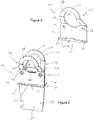
Figure 5 is a perspective view of a second embodiment of clip according the present invention; and -
Figure 6 is a perspective view of a one-piece storage clip set according to the present invention. - Referring initially to
Figures 1 and 2 , there is shown amountain bike cleat 10 for connection to a clipless cycling shoe 11. Themountain bike cleat 10 is secured to the bottom of the shoe 11 using threadedbolts 12 and the shoe 11 is then able to secure to a clipless pedal (not shown) on a mountain bike in order to temporarily connect the shoe 11 to the pedal.Mountain bike cleats 10 are designed to secure in arecess 13 formed in the sole 14 of the cycling shoe 11 and this enables the shoe to be used when not cycling with less discomfort to the user. The other main type of cleat is a road cleat (not shown) and this is designed to secure to a surface on the sole of a shoe, rather than in a recess. Road cycling shoes provide a good power transfer but can be more uncomfortable to use when not cycling. - Both road and
mountain bike cleats 10 operate in the same way insofar as they secure to a pedal (not shown) by having afront edge 15 which locates in an opening provided in the front of the pedal. A spring-loaded hook at the rear of the pedal then snaps over aledge 16 at the rear of thecleat 17. - Referring now to
Figures 3 and 4 , there is shown a first embodiment ofstorage clip 20 for use with amountain bike cleat 10. Theclip 20 includes abase plate 21 which is generally planar and which has twocylindrical openings 22 configured for connection of securing means, such as screws (not shown) to enable theclip 20 to be secured to a wall. Anarm 23 extends from thebase plate 21 through a curved corner configuration leading to anintermediate section 24 which is disposed generally at a right angle relative to the base plate. Anend section 25 is bent in a curve round such that it extends from theintermediate section 24 generally parallel to and away from thebase plate 21. Anopening 26 is formed through the arm and this is shaped to engage thefront edge 15 of amountain bike cleat 10. Theopening 26 extends between thebase plate 21, theintermediate section 24 and theend section 25 of thearm 23. - Extending from the
base plate 21 at the end opposed to thearm 23 is a retainingtab 29. The retainingtab 29 extends at an acute angle to thebase plate 21 towards thearm 23 and defines afree edge 30 and two opposed side edges 31. The retainingtab 29 is generally planar but includes a T-shapedrecess 32 formed midway along thefree edge 30 to define twoflanges 33 either side. The retainingtab 29 is configured to resiliently deform so that the twoflanges 33 can engage therear edge 17 of a mountain bike cleat, as shown inFigure 4 . - A
second opening 36 is formed through thebase plate 21 in the corner region between thebase pate 21 and the retainingtab 29. The provision of asecond opening 36 serves to increase the flexibilty of theclip 20 and also requires less material thus minimising manufacturing costs and ensuring a small and tidy design. - Referring now to
Figures 5 and 6 , there is shown a second embodiment ofstorage clip 40 for use with a road cleat (not shown). Thisclip 40 is very similar to the mountainbike cleat clip 20 and includes a planar base plate 41 having twoopenings 42 for the connection of securing means 43. - An
arm 46 extends from the base plate 41 of theroad cleat clip 40, at an angle, leading to anintermediate section 47. Anend section 48 extends at an angle from theintermediate section 47. A generallycircular opening 49 is formed through thearm 46 and this is shaped to engage the front edge of a road cleat. Theopening 49 extends between the base plate 41, theintermediate section 47 and theend section 48 of thearm 46. - As with the first embodiment, a retaining
tab 52 extends from the base plate 41. The retainingtab 52 extends from the base plate 41 at less than 90 degrees and defines afree edge 53 and two opposed side edges 54. The retainingtab 52 is generally planar but includes a substantiallyrectangular flange 55 extending midway along thefree edge 53. The retainingtab 52 extends further in the region of theflange 55 so that the flange is offset from thefree edge 53. The retainingtab 52 is configured to resiliently deform so that theflange 55 can engage the rear edge of a road cleat (not shown). - The mountain bike and road cleat clips 20, 40 are formed from a single piece of material. This ensures that the clips are robust and means that the manufacture thereof is cost effective. Additionally, the single form design ensures that the clips can be smaller and more aesthetically pleasing than clips formed from more than one connected part.
- As shown in
Figure 6 , arelease member 58 may be connected to eachclip release member 58 is planar and includes two holes (not visible) appropriately spaced so as to align with theholes 42 formed in the base plate 41. Therelease member 58 is designed to abut and to extend beyond the base plate 41 to provide alever 59 for a user to grip to remove the clip from a cleat. A generally rectangular opening 60 at one end of therelease member 58, adjacent the base plate 41, allows a securing clip (such as a carabiner) to be connected to releasemember 58. Part of the edge of thelever 59 is profiled to formlips 61 which can be used to open a bottle. - In use, the
clips clip holes base plate 21, 41. The cleat on a shoe may then be attached to the mountedclip arm tab - The clips may also be used to secure clipless cycling shoes together as shown in
Figure 6 . This may be beneficial for storing the shoes and enables the shoes to be easily transported together. This may be achieved by securing the base plates 41 of twoclips 40 together back to back by way of securing members, such asbolts 43 through theholes 42. If desired, as shown inFigure 6 , arelease member 58 can be secured between theclips 40 to assist with removal of theclips 40 from the cleats.
Claims (14)
- A one-piece storage clip for shoes having cleats, the clip being arranged to secure to the cleat of a shoe, the clip comprising a generally planar base plate having an arm extending therefrom, the arm defining an opening for engaging the front edge of a cleat and a retaining tab carried by the base plate and arranged to engage the rear edge of a cleat by resilient deformation of the retaining tab.
- A one-piece storage clip as claimed in claim 1 wherein one or more hole is defined through the base plate into which a securing member can be inserted.
- A one-piece storage clip as claimed in claim 1 or claim 2, wherein the arm has a free end remote from the base plate and wherein the arm comprises an intermediate section adjacent the base plate and an end section at the free end.
- A one-piece storage clip as claimed in claim 3, wherein the intermediate section extends at an angle with respect to the base plate.
- A one-piece storage clip as claimed in claim 3 or claim 4, wherein the end section of the arm extends at an angle with respect to the intermediate section of the arm.
- A one-piece storage clip as claimed in any of the preceding claims, wherein the retaining tab extends at an angle with respect to the base plate.
- A one-piece storage clip as claimed in any of the preceding claims wherein the clip is generally U-shaped in cross section.
- A one-piece storage clip as claimed in any of the preceding claims, in which the retaining tab has a free edge and two opposed side edges.
- A one-piece storage clip as claimed in claim 8, wherein a flange extends from the free edge.
- A one-piece storage clip as claimed in claim 8, wherein a recess is formed along the free edge of the retaining tab.
- A one-piece storage clip as claimed in any of the preceding claims further comprising a release member configured for connection to the base plate for removing the clip from a cleat.
- A one-piece storage clip as claimed in claims 11, wherein at least a part of the release member includes a profile defined to serve as a bottle opener.
- A one-piece storage clip as claimed in any of claims 11 to 12 wherein the release member further defines an opening for the attachment of a securing clip.
- A one-piece storage clip set comprising two one-piece storage clips, as claimed in any of claims 1 to 13 and a release member configured for connection to the base plate of each storage clip for removing the clips from cleats.
Applications Claiming Priority (1)
| Application Number | Priority Date | Filing Date | Title |
|---|---|---|---|
| GBGB1703216.0A GB201703216D0 (en) | 2017-02-28 | 2017-02-28 | Storage clip |
Publications (2)
| Publication Number | Publication Date |
|---|---|
| EP3366169A1 true EP3366169A1 (en) | 2018-08-29 |
| EP3366169B1 EP3366169B1 (en) | 2021-11-10 |
Family
ID=58544263
Family Applications (1)
| Application Number | Title | Priority Date | Filing Date |
|---|---|---|---|
| EP18159239.5A Active EP3366169B1 (en) | 2017-02-28 | 2018-02-28 | Storage clip for cycling shoes having cleats |
Country Status (2)
| Country | Link |
|---|---|
| EP (1) | EP3366169B1 (en) |
| GB (1) | GB201703216D0 (en) |
Cited By (1)
| Publication number | Priority date | Publication date | Assignee | Title |
|---|---|---|---|---|
| DE102022212591A1 (en) * | 2022-11-24 | 2024-05-29 | Shimano Inc. | CLEAT PLATE FOR A SHOE, PEDAL SYSTEM FOR A HUMAN-PROPELLED VEHICLE AND PEDAL FOR A HUMAN-PROPELLED VEHICLE |
Citations (2)
| Publication number | Priority date | Publication date | Assignee | Title |
|---|---|---|---|---|
| GB1061309A (en) * | 1965-01-26 | 1967-03-08 | Schweiger And Schweizer Ag | Shoe stand |
| US20070137430A1 (en) * | 2005-10-24 | 2007-06-21 | Kuo-Chih Chao | Pedal structure without front clamping members |
-
2017
- 2017-02-28 GB GBGB1703216.0A patent/GB201703216D0/en not_active Ceased
-
2018
- 2018-02-28 EP EP18159239.5A patent/EP3366169B1/en active Active
Patent Citations (2)
| Publication number | Priority date | Publication date | Assignee | Title |
|---|---|---|---|---|
| GB1061309A (en) * | 1965-01-26 | 1967-03-08 | Schweiger And Schweizer Ag | Shoe stand |
| US20070137430A1 (en) * | 2005-10-24 | 2007-06-21 | Kuo-Chih Chao | Pedal structure without front clamping members |
Cited By (1)
| Publication number | Priority date | Publication date | Assignee | Title |
|---|---|---|---|---|
| DE102022212591A1 (en) * | 2022-11-24 | 2024-05-29 | Shimano Inc. | CLEAT PLATE FOR A SHOE, PEDAL SYSTEM FOR A HUMAN-PROPELLED VEHICLE AND PEDAL FOR A HUMAN-PROPELLED VEHICLE |
Also Published As
| Publication number | Publication date |
|---|---|
| GB201703216D0 (en) | 2017-04-12 |
| EP3366169B1 (en) | 2021-11-10 |
Similar Documents
| Publication | Publication Date | Title |
|---|---|---|
| USD839078S1 (en) | Slide clip | |
| US3091487A (en) | Clip | |
| US8011544B1 (en) | Hinged pocket | |
| US20150060316A1 (en) | Tool box | |
| US6189242B1 (en) | Shoe for bicycle | |
| US10051958B2 (en) | Fastening part of a storage system | |
| US20140183312A1 (en) | Shelving system and components | |
| RU2015151928A (en) | DOCKING SYSTEM (OPTIONS), FRONT PLATE FOR THE WALL OF THE FREIGHT VEHICLE PLATFORM AND THE FREIGHT VEHICLE PLATFORM | |
| EP3366169B1 (en) | Storage clip for cycling shoes having cleats | |
| US9964255B2 (en) | Behind-wall television monitor wall mount | |
| JP2017538625A (en) | Vehicle roof rail | |
| EP1129634B1 (en) | Fastener for footwear | |
| US10267379B2 (en) | Counterweight assembly | |
| US20140312124A1 (en) | Rfid assembly including spring clip | |
| US11717103B2 (en) | Hanger | |
| US3448952A (en) | Electrical box mounting clip | |
| US20040004096A1 (en) | Auxiliary bar for a hanger | |
| WO2010093144A2 (en) | Dustpan that is adaptive to the human body | |
| US9663176B1 (en) | Strut fixing device | |
| CN210240786U (en) | Pipeline fixing device for fire prevention valve | |
| US9173447B2 (en) | Shoe protecting cover device | |
| US10307022B1 (en) | Towel caddy hook with frictional attachment | |
| US20230182645A1 (en) | Seat back cover having storage section for vehicle | |
| US20160297369A1 (en) | Umbrella mounting system | |
| TW201529017A (en) | Shelf and tag-holder |
Legal Events
| Date | Code | Title | Description |
|---|---|---|---|
| PUAI | Public reference made under article 153(3) epc to a published international application that has entered the european phase |
Free format text: ORIGINAL CODE: 0009012 |
|
| STAA | Information on the status of an ep patent application or granted ep patent |
Free format text: STATUS: THE APPLICATION HAS BEEN PUBLISHED |
|
| AK | Designated contracting states |
Kind code of ref document: A1 Designated state(s): AL AT BE BG CH CY CZ DE DK EE ES FI FR GB GR HR HU IE IS IT LI LT LU LV MC MK MT NL NO PL PT RO RS SE SI SK SM TR |
|
| AX | Request for extension of the european patent |
Extension state: BA ME |
|
| STAA | Information on the status of an ep patent application or granted ep patent |
Free format text: STATUS: REQUEST FOR EXAMINATION WAS MADE |
|
| 17P | Request for examination filed |
Effective date: 20190228 |
|
| RBV | Designated contracting states (corrected) |
Designated state(s): AL AT BE BG CH CY CZ DE DK EE ES FI FR GB GR HR HU IE IS IT LI LT LU LV MC MK MT NL NO PL PT RO RS SE SI SK SM TR |
|
| GRAP | Despatch of communication of intention to grant a patent |
Free format text: ORIGINAL CODE: EPIDOSNIGR1 |
|
| STAA | Information on the status of an ep patent application or granted ep patent |
Free format text: STATUS: GRANT OF PATENT IS INTENDED |
|
| INTG | Intention to grant announced |
Effective date: 20210604 |
|
| GRAS | Grant fee paid |
Free format text: ORIGINAL CODE: EPIDOSNIGR3 |
|
| GRAA | (expected) grant |
Free format text: ORIGINAL CODE: 0009210 |
|
| STAA | Information on the status of an ep patent application or granted ep patent |
Free format text: STATUS: THE PATENT HAS BEEN GRANTED |
|
| AK | Designated contracting states |
Kind code of ref document: B1 Designated state(s): AL AT BE BG CH CY CZ DE DK EE ES FI FR GB GR HR HU IE IS IT LI LT LU LV MC MK MT NL NO PL PT RO RS SE SI SK SM TR |
|
| REG | Reference to a national code |
Ref country code: GB Ref legal event code: FG4D |
|
| REG | Reference to a national code |
Ref country code: AT Ref legal event code: REF Ref document number: 1445273 Country of ref document: AT Kind code of ref document: T Effective date: 20211115 Ref country code: CH Ref legal event code: EP |
|
| REG | Reference to a national code |
Ref country code: DE Ref legal event code: R096 Ref document number: 602018026316 Country of ref document: DE |
|
| REG | Reference to a national code |
Ref country code: IE Ref legal event code: FG4D |
|
| REG | Reference to a national code |
Ref country code: LT Ref legal event code: MG9D |
|
| REG | Reference to a national code |
Ref country code: NL Ref legal event code: MP Effective date: 20211110 |
|
| REG | Reference to a national code |
Ref country code: AT Ref legal event code: MK05 Ref document number: 1445273 Country of ref document: AT Kind code of ref document: T Effective date: 20211110 |
|
| PG25 | Lapsed in a contracting state [announced via postgrant information from national office to epo] |
Ref country code: RS Free format text: LAPSE BECAUSE OF FAILURE TO SUBMIT A TRANSLATION OF THE DESCRIPTION OR TO PAY THE FEE WITHIN THE PRESCRIBED TIME-LIMIT Effective date: 20211110 Ref country code: LT Free format text: LAPSE BECAUSE OF FAILURE TO SUBMIT A TRANSLATION OF THE DESCRIPTION OR TO PAY THE FEE WITHIN THE PRESCRIBED TIME-LIMIT Effective date: 20211110 Ref country code: FI Free format text: LAPSE BECAUSE OF FAILURE TO SUBMIT A TRANSLATION OF THE DESCRIPTION OR TO PAY THE FEE WITHIN THE PRESCRIBED TIME-LIMIT Effective date: 20211110 Ref country code: BG Free format text: LAPSE BECAUSE OF FAILURE TO SUBMIT A TRANSLATION OF THE DESCRIPTION OR TO PAY THE FEE WITHIN THE PRESCRIBED TIME-LIMIT Effective date: 20220210 Ref country code: AT Free format text: LAPSE BECAUSE OF FAILURE TO SUBMIT A TRANSLATION OF THE DESCRIPTION OR TO PAY THE FEE WITHIN THE PRESCRIBED TIME-LIMIT Effective date: 20211110 |
|
| PG25 | Lapsed in a contracting state [announced via postgrant information from national office to epo] |
Ref country code: IS Free format text: LAPSE BECAUSE OF FAILURE TO SUBMIT A TRANSLATION OF THE DESCRIPTION OR TO PAY THE FEE WITHIN THE PRESCRIBED TIME-LIMIT Effective date: 20220310 Ref country code: SE Free format text: LAPSE BECAUSE OF FAILURE TO SUBMIT A TRANSLATION OF THE DESCRIPTION OR TO PAY THE FEE WITHIN THE PRESCRIBED TIME-LIMIT Effective date: 20211110 Ref country code: PT Free format text: LAPSE BECAUSE OF FAILURE TO SUBMIT A TRANSLATION OF THE DESCRIPTION OR TO PAY THE FEE WITHIN THE PRESCRIBED TIME-LIMIT Effective date: 20220310 Ref country code: PL Free format text: LAPSE BECAUSE OF FAILURE TO SUBMIT A TRANSLATION OF THE DESCRIPTION OR TO PAY THE FEE WITHIN THE PRESCRIBED TIME-LIMIT Effective date: 20211110 Ref country code: NO Free format text: LAPSE BECAUSE OF FAILURE TO SUBMIT A TRANSLATION OF THE DESCRIPTION OR TO PAY THE FEE WITHIN THE PRESCRIBED TIME-LIMIT Effective date: 20220210 Ref country code: NL Free format text: LAPSE BECAUSE OF FAILURE TO SUBMIT A TRANSLATION OF THE DESCRIPTION OR TO PAY THE FEE WITHIN THE PRESCRIBED TIME-LIMIT Effective date: 20211110 Ref country code: LV Free format text: LAPSE BECAUSE OF FAILURE TO SUBMIT A TRANSLATION OF THE DESCRIPTION OR TO PAY THE FEE WITHIN THE PRESCRIBED TIME-LIMIT Effective date: 20211110 Ref country code: HR Free format text: LAPSE BECAUSE OF FAILURE TO SUBMIT A TRANSLATION OF THE DESCRIPTION OR TO PAY THE FEE WITHIN THE PRESCRIBED TIME-LIMIT Effective date: 20211110 Ref country code: GR Free format text: LAPSE BECAUSE OF FAILURE TO SUBMIT A TRANSLATION OF THE DESCRIPTION OR TO PAY THE FEE WITHIN THE PRESCRIBED TIME-LIMIT Effective date: 20220211 Ref country code: ES Free format text: LAPSE BECAUSE OF FAILURE TO SUBMIT A TRANSLATION OF THE DESCRIPTION OR TO PAY THE FEE WITHIN THE PRESCRIBED TIME-LIMIT Effective date: 20211110 |
|
| PG25 | Lapsed in a contracting state [announced via postgrant information from national office to epo] |
Ref country code: SM Free format text: LAPSE BECAUSE OF FAILURE TO SUBMIT A TRANSLATION OF THE DESCRIPTION OR TO PAY THE FEE WITHIN THE PRESCRIBED TIME-LIMIT Effective date: 20211110 Ref country code: SK Free format text: LAPSE BECAUSE OF FAILURE TO SUBMIT A TRANSLATION OF THE DESCRIPTION OR TO PAY THE FEE WITHIN THE PRESCRIBED TIME-LIMIT Effective date: 20211110 Ref country code: RO Free format text: LAPSE BECAUSE OF FAILURE TO SUBMIT A TRANSLATION OF THE DESCRIPTION OR TO PAY THE FEE WITHIN THE PRESCRIBED TIME-LIMIT Effective date: 20211110 Ref country code: EE Free format text: LAPSE BECAUSE OF FAILURE TO SUBMIT A TRANSLATION OF THE DESCRIPTION OR TO PAY THE FEE WITHIN THE PRESCRIBED TIME-LIMIT Effective date: 20211110 Ref country code: DK Free format text: LAPSE BECAUSE OF FAILURE TO SUBMIT A TRANSLATION OF THE DESCRIPTION OR TO PAY THE FEE WITHIN THE PRESCRIBED TIME-LIMIT Effective date: 20211110 Ref country code: CZ Free format text: LAPSE BECAUSE OF FAILURE TO SUBMIT A TRANSLATION OF THE DESCRIPTION OR TO PAY THE FEE WITHIN THE PRESCRIBED TIME-LIMIT Effective date: 20211110 |
|
| REG | Reference to a national code |
Ref country code: DE Ref legal event code: R097 Ref document number: 602018026316 Country of ref document: DE |
|
| REG | Reference to a national code |
Ref country code: DE Ref legal event code: R119 Ref document number: 602018026316 Country of ref document: DE |
|
| PLBE | No opposition filed within time limit |
Free format text: ORIGINAL CODE: 0009261 |
|
| STAA | Information on the status of an ep patent application or granted ep patent |
Free format text: STATUS: NO OPPOSITION FILED WITHIN TIME LIMIT |
|
| PG25 | Lapsed in a contracting state [announced via postgrant information from national office to epo] |
Ref country code: MC Free format text: LAPSE BECAUSE OF FAILURE TO SUBMIT A TRANSLATION OF THE DESCRIPTION OR TO PAY THE FEE WITHIN THE PRESCRIBED TIME-LIMIT Effective date: 20211110 |
|
| REG | Reference to a national code |
Ref country code: CH Ref legal event code: PL |
|
| 26N | No opposition filed |
Effective date: 20220811 |
|
| REG | Reference to a national code |
Ref country code: BE Ref legal event code: MM Effective date: 20220228 |
|
| PG25 | Lapsed in a contracting state [announced via postgrant information from national office to epo] |
Ref country code: LU Free format text: LAPSE BECAUSE OF NON-PAYMENT OF DUE FEES Effective date: 20220228 Ref country code: AL Free format text: LAPSE BECAUSE OF FAILURE TO SUBMIT A TRANSLATION OF THE DESCRIPTION OR TO PAY THE FEE WITHIN THE PRESCRIBED TIME-LIMIT Effective date: 20211110 |
|
| PG25 | Lapsed in a contracting state [announced via postgrant information from national office to epo] |
Ref country code: SI Free format text: LAPSE BECAUSE OF FAILURE TO SUBMIT A TRANSLATION OF THE DESCRIPTION OR TO PAY THE FEE WITHIN THE PRESCRIBED TIME-LIMIT Effective date: 20211110 |
|
| PG25 | Lapsed in a contracting state [announced via postgrant information from national office to epo] |
Ref country code: FR Free format text: LAPSE BECAUSE OF NON-PAYMENT OF DUE FEES Effective date: 20220228 |
|
| PG25 | Lapsed in a contracting state [announced via postgrant information from national office to epo] |
Ref country code: LI Free format text: LAPSE BECAUSE OF NON-PAYMENT OF DUE FEES Effective date: 20220228 Ref country code: IE Free format text: LAPSE BECAUSE OF NON-PAYMENT OF DUE FEES Effective date: 20220228 Ref country code: DE Free format text: LAPSE BECAUSE OF NON-PAYMENT OF DUE FEES Effective date: 20220901 Ref country code: CH Free format text: LAPSE BECAUSE OF NON-PAYMENT OF DUE FEES Effective date: 20220228 |
|
| PG25 | Lapsed in a contracting state [announced via postgrant information from national office to epo] |
Ref country code: BE Free format text: LAPSE BECAUSE OF NON-PAYMENT OF DUE FEES Effective date: 20220228 |
|
| PG25 | Lapsed in a contracting state [announced via postgrant information from national office to epo] |
Ref country code: IT Free format text: LAPSE BECAUSE OF FAILURE TO SUBMIT A TRANSLATION OF THE DESCRIPTION OR TO PAY THE FEE WITHIN THE PRESCRIBED TIME-LIMIT Effective date: 20211110 |
|
| PG25 | Lapsed in a contracting state [announced via postgrant information from national office to epo] |
Ref country code: HU Free format text: LAPSE BECAUSE OF FAILURE TO SUBMIT A TRANSLATION OF THE DESCRIPTION OR TO PAY THE FEE WITHIN THE PRESCRIBED TIME-LIMIT; INVALID AB INITIO Effective date: 20180228 |
|
| PG25 | Lapsed in a contracting state [announced via postgrant information from national office to epo] |
Ref country code: MK Free format text: LAPSE BECAUSE OF FAILURE TO SUBMIT A TRANSLATION OF THE DESCRIPTION OR TO PAY THE FEE WITHIN THE PRESCRIBED TIME-LIMIT Effective date: 20211110 Ref country code: CY Free format text: LAPSE BECAUSE OF FAILURE TO SUBMIT A TRANSLATION OF THE DESCRIPTION OR TO PAY THE FEE WITHIN THE PRESCRIBED TIME-LIMIT Effective date: 20211110 |
|
| PG25 | Lapsed in a contracting state [announced via postgrant information from national office to epo] |
Ref country code: MT Free format text: LAPSE BECAUSE OF FAILURE TO SUBMIT A TRANSLATION OF THE DESCRIPTION OR TO PAY THE FEE WITHIN THE PRESCRIBED TIME-LIMIT Effective date: 20211110 |
|
| PGFP | Annual fee paid to national office [announced via postgrant information from national office to epo] |
Ref country code: GB Payment date: 20250226 Year of fee payment: 8 |
|
| PG25 | Lapsed in a contracting state [announced via postgrant information from national office to epo] |
Ref country code: TR Free format text: LAPSE BECAUSE OF FAILURE TO SUBMIT A TRANSLATION OF THE DESCRIPTION OR TO PAY THE FEE WITHIN THE PRESCRIBED TIME-LIMIT Effective date: 20211110 |