EP3365144B1 - Humanoid robot foot comprising an active variable stiffness mechanism - Google Patents
Humanoid robot foot comprising an active variable stiffness mechanism Download PDFInfo
- Publication number
- EP3365144B1 EP3365144B1 EP16794224.2A EP16794224A EP3365144B1 EP 3365144 B1 EP3365144 B1 EP 3365144B1 EP 16794224 A EP16794224 A EP 16794224A EP 3365144 B1 EP3365144 B1 EP 3365144B1
- Authority
- EP
- European Patent Office
- Prior art keywords
- roller assembly
- leaf spring
- foot
- contact
- stiffness
- Prior art date
- Legal status (The legal status is an assumption and is not a legal conclusion. Google has not performed a legal analysis and makes no representation as to the accuracy of the status listed.)
- Active
Links
- 230000007246 mechanism Effects 0.000 title claims description 16
- 230000033001 locomotion Effects 0.000 claims description 9
- 230000007423 decrease Effects 0.000 claims description 2
- 210000002683 foot Anatomy 0.000 description 43
- 210000003371 toe Anatomy 0.000 description 14
- 239000000463 material Substances 0.000 description 2
- RTAQQCXQSZGOHL-UHFFFAOYSA-N Titanium Chemical compound [Ti] RTAQQCXQSZGOHL-UHFFFAOYSA-N 0.000 description 1
- 230000001419 dependent effect Effects 0.000 description 1
- 239000013013 elastic material Substances 0.000 description 1
- 238000005265 energy consumption Methods 0.000 description 1
- 230000005021 gait Effects 0.000 description 1
- 230000001788 irregular Effects 0.000 description 1
- 210000003127 knee Anatomy 0.000 description 1
- 230000003278 mimic effect Effects 0.000 description 1
- 238000011084 recovery Methods 0.000 description 1
- 238000007493 shaping process Methods 0.000 description 1
- 229910052719 titanium Inorganic materials 0.000 description 1
- 239000010936 titanium Substances 0.000 description 1
Images


Classifications
-
- B—PERFORMING OPERATIONS; TRANSPORTING
- B25—HAND TOOLS; PORTABLE POWER-DRIVEN TOOLS; MANIPULATORS
- B25J—MANIPULATORS; CHAMBERS PROVIDED WITH MANIPULATION DEVICES
- B25J19/00—Accessories fitted to manipulators, e.g. for monitoring, for viewing; Safety devices combined with or specially adapted for use in connection with manipulators
- B25J19/06—Safety devices
- B25J19/068—Actuating means with variable stiffness
-
- B—PERFORMING OPERATIONS; TRANSPORTING
- B25—HAND TOOLS; PORTABLE POWER-DRIVEN TOOLS; MANIPULATORS
- B25J—MANIPULATORS; CHAMBERS PROVIDED WITH MANIPULATION DEVICES
- B25J19/00—Accessories fitted to manipulators, e.g. for monitoring, for viewing; Safety devices combined with or specially adapted for use in connection with manipulators
- B25J19/0008—Balancing devices
- B25J19/0016—Balancing devices using springs
-
- B—PERFORMING OPERATIONS; TRANSPORTING
- B25—HAND TOOLS; PORTABLE POWER-DRIVEN TOOLS; MANIPULATORS
- B25J—MANIPULATORS; CHAMBERS PROVIDED WITH MANIPULATION DEVICES
- B25J19/00—Accessories fitted to manipulators, e.g. for monitoring, for viewing; Safety devices combined with or specially adapted for use in connection with manipulators
- B25J19/02—Sensing devices
-
- B—PERFORMING OPERATIONS; TRANSPORTING
- B62—LAND VEHICLES FOR TRAVELLING OTHERWISE THAN ON RAILS
- B62D—MOTOR VEHICLES; TRAILERS
- B62D57/00—Vehicles characterised by having other propulsion or other ground- engaging means than wheels or endless track, alone or in addition to wheels or endless track
- B62D57/02—Vehicles characterised by having other propulsion or other ground- engaging means than wheels or endless track, alone or in addition to wheels or endless track with ground-engaging propulsion means, e.g. walking members
- B62D57/032—Vehicles characterised by having other propulsion or other ground- engaging means than wheels or endless track, alone or in addition to wheels or endless track with ground-engaging propulsion means, e.g. walking members with alternately or sequentially lifted supporting base and legs; with alternately or sequentially lifted feet or skid
Definitions
- the present invention relates to a humanoid robot foot comprising an active variable stiffness mechanism to adjust the stiffness of at least one flexible toe of the foot.
- the active variable stiffness mechanism comprises at least one flexible member and a stiffness adjustment device arranged to actively adjust the stiffness of said at least one flexible member.
- Active variable stiffness mechanisms have already been developed, but these mechanisms are designed for rotational joints and are not suitable for use on relatively small humanoid robot feet.
- other known solutions use an active toe as an impedance regulator to improve balancing during the standing phase and when the humanoid robot starts or stops walking.
- VANDERBORGHT B ET AL "Variable impedance actuators: A review "
- HAM R ET AL “Compliant actuator designs” and CN103753604A .
- the invention is based on the idea of making the at least one flexible toe of the foot as a leaf spring having a rear portion rigidly connected to a flat surface of the foot base, a front portion projecting from the foot base and an intermediate portion which is not connected to the foot base and is therefore freely deflectable, along with the front portion, as a result of the application of an external force on the front portion, and providing a stiffness adjustment device comprising a roller assembly, which is held in contact with the intermediate portion of the at least one leaf spring and is movable relative to the at least one leaf spring, and an actuation unit arranged to move the roller assembly and hence the point of contact of the roller assembly with the at least one leaf spring, thereby varying the length of the cantilevered portion of the at least one leaf spring and hence the stiffness of the at least one leaf spring.
- the at least one leaf spring is shaped such that its width at the contact point with the roller assembly varies depending on the position of the roller assembly.
- the stiffness of the at least one leaf spring depends on the position of the roller assembly not only because the spring length depends on the position of the roller assembly, but also because the spring width depends on the position of the roller assembly.
- a foot for a humanoid robot is generally indicated 10.
- the foot 10 basically comprises a foot base 12 made as a rigid body and at least one leaf spring 14 (in the illustrated embodiment, two leaf springs) acting as flexible toes of the foot.
- the leaf springs 14 are attached with rear ends thereof to the foot base 12 and extend forwards from the latter in a cantilevered fashion.
- Each leaf spring 14 carries at a free end thereof a respective front contact member 16 for contact with the ground.
- a rear contact member 18 is also provided for and is attached to the rear end of the foot base 12.
- each of the front contact members 16 comprises a rubber ball 20 and a pressure sensor 22 for measuring the pressure applied to the rubber ball 20.
- each leaf spring 14 comprises a rear portion 14a rigidly connected to the foot base 12, a front portion 14b projecting from a front edge 12a of the foot base 12 and an intermediate portion 14c interposed between the rear portion 14a and the front portion 14b.
- the front contact members 16 are mounted on the front portions 14b of the respective leaf springs 14.
- the intermediate portion 14c extends above an upper flat surface 12b of the foot base 12 and is not attached to the foot base 12 so as to be free to deflect, along with the front portion 14b, as a result of the application of an external force F onto the respective leaf spring 14.
- the leaf springs 14 are deflectable independently of each other, which is particularly useful when the foot is placed on different surface levels.
- the leaf springs 14 are made for example of titanium, but may of course be made of any other suitable material.
- the foot 10 further comprises a stiffness adjustment device, generally indicated 26, for actively adjusting the stiffness K of the leaf springs 14 by varying the spring length l .
- the stiffness adjustment device 26 comprises first of all a roller assembly 28 which is held in contact with the leaf springs 14, in particular with the intermediate portions 14c thereof, so as to press the leaf springs 14 against the upper flat surface 12b of the foot base 12.
- the roller assembly 28 is freely rotatable about an axis of rotation y extending in the transverse direction, i.e. in a horizontal direction perpendicular to the longitudinal axis x.
- the roller assembly 28 is movable in the longitudinal direction x relative to the leaf springs 14 so as to vary the point of contact P between the roller assembly 28 and the leaf springs 14.
- the roller assembly 28 is guided at its end portions by a pair of guide members 32 mounted on the foot base 12 ( Figure 4 ).
- the stiffness adjustment device 26 further comprises an actuation unit 34 arranged to control the movement of the roller assembly 28 in the longitudinal direction x.
- the actuation unit 34 comprises a rotary actuator 36, for example an electric motor, and a crank mechanism arranged to convert the rotary motion generated by the rotary actuator 36 about an axis of rotation y1 parallel to the axis of rotation y of the roller assembly 28 into the translational motion of the roller assembly 28 along the longitudinal axis x.
- the crank mechanism comprises for example a pair of cranks 38, which are arranged to be driven by the rotary actuator 36 to rotate about the axis of rotation y1, and a pair of connecting rods 40, each of which is hinged at a first end thereof to a respective crank 38 and at the opposite end to the roller assembly 28.
- the leaf springs 14 are shaped in such a manner that their width at the point of contact P does not remain constant, but changes, as the point of contact P moves in the longitudinal direction x as a result of the movement of the roller assembly 28 controlled by the actuation unit 34.
- the stiffness K of the leaf springs 14 changes with the longitudinal position s of the point of contact P not only because the spring length l changes, but also because the spring width w changes.
- the roller assembly 28 comprises three rotating elements, namely two outer elements 42 and a middle element 44, which are rotatable independently of each other about the axis of rotation y.
- Providing separate rotating elements (in the present case, three elements) which rotate independently of each other about the same axis of rotation allows to minimize the frictional torques acting on the roller assembly 28.
- each of the two outer elements 42 has a cylindrical body 42a in contact with its lateral surface on a respective leaf spring 14 and a shaft 42b projecting axially from the cylindrical body 42a.
- the two outer elements 42 are arranged with their shafts 42b facing each other, i.e.
- the middle element 44 is made as a hollow cylindrical body which is rotatably supported on the shafts 42b of the two outer elements 42 and is in contact with its lateral surface on both the leaf springs 14.
- the middle element 44 has a circumferential groove 46 extending throughout the lateral surface of that element.
- a protrusion 48 engages, which is formed by the foot base 12 and extends along the longitudinal axis x to mechanically constrain the roller assembly 28 to move along this axis.
- the connecting rods 40 of the crank mechanism of stiffness adjustment device 26 are hinged to the shafts 42b of the two outer elements 42 of the roller assembly 28.
- the roller assembly 28 further comprises a pair of cam followers 50 which are rotatably mounted at the outer ends of the two outer elements 42 and engage each with a respective one of the guide members 32 to ensure that the three rotating elements 42 and 44 of the roller assembly 28 are held in contact with the leaf springs 14.
- the present inventions provides a simple and compact mechanism for actively varying the stiffness of a flexible toe of a humanoid robot foot, thus allowing to change the stiffness of the flexible toes depending for example on the characteristics of the terrain and hence to improve the ability of the robot to walk on uneven terrains.
- the following example is given as background art, and is not belonging to the invention. It is related to an active variable stiffness mechanism for actively changing the stiffness of at least one flexible member made as a leaf spring, wherein the at least one leaf spring is mounted on a support base of the mechanism and has a rear portion rigidly connected to a flat surface of the support base, a front portion projecting from the support base and an intermediate portion which is not rigidly connected to the support base and is therefore freely deflectable, along with the front portion, as a result of the application of an external force on the front portion, and wherein the mechanism further comprises a stiffness adjustment device including a roller assembly, which is held in contact with the intermediate portion of the at least one leaf spring and is movable relative to the at least one leaf spring along a longitudinal axis of the at least one leaf spring, and an actuation unit arranged to move the roller assembly, and hence the point of contact of the roller assembly with the at least one leaf spring, thereby varying the length of the cantilevered portion of the at least one leaf spring, and
Landscapes
- Engineering & Computer Science (AREA)
- Mechanical Engineering (AREA)
- Robotics (AREA)
- Chemical & Material Sciences (AREA)
- Combustion & Propulsion (AREA)
- Transportation (AREA)
- Manipulator (AREA)
- Toys (AREA)
Description
- The present invention relates to a humanoid robot foot comprising an active variable stiffness mechanism to adjust the stiffness of at least one flexible toe of the foot. The active variable stiffness mechanism comprises at least one flexible member and a stiffness adjustment device arranged to actively adjust the stiffness of said at least one flexible member.
- During last decade many humanoid robots have been developed with improved balancing and push recovery abilities, as well as with the capability of locomotion and running on irregular terrain. Most of these robots have employed simple flat rectangular feet using an elastic material as a foot sole. This foot design is very popular but makes it difficult to mimic human-like locomotion, particularly on uneven terrain. Furthermore, a large number of humanoid robots with gait based on the zero moment point principle and on the inverted pendulum principle have serious drawbacks in terms of locomotion on uneven terrain and excessive energy consumption due to large knee angles during the walking cycle.
- In order to overcome some of these limitations, researchers have proposed feet provided with toes and have introduced stiffness in the feet design. For example, a flexible passive toe has been simply introduced by adding one joint and torsional springs controlling rotation of this joint. A foot for humanoid robot provided with a flexible passive toe of the above-mentioned type is disclosed for example in
CN103057620 . - Humanoid robot feet related to the invention are disclosed in JINYING ZHU ET AL: "PANTOE 1: Biomechanical design of powered ankle-foot prosthesis with compliant joints and segmented foot" and
US2004/064195A1 . - Active variable stiffness mechanisms have already been developed, but these mechanisms are designed for rotational joints and are not suitable for use on relatively small humanoid robot feet. On the other hand, other known solutions use an active toe as an impedance regulator to improve balancing during the standing phase and when the humanoid robot starts or stops walking.
- Variable stiffness mechanisms related to the invention are disclosed in VANDERBORGHT B ET AL: "Variable impedance actuators: A review", HAM R ET AL: "Compliant actuator designs" and
CN103753604A . - It is the object of the present invention to provide a humanoid robot foot comprising a mechanism which is able to actively adjust the stiffness of a flexible member and which is simple and compact.
- This and other objects are fully achieved according to the present invention by virtue of a humanoid robot foot as defined in independent claim 1.
- Advantageous embodiments of the present invention are the subject-matter of the dependent claims, the content of which is to be intended as forming an integral and integrating part of the following description.
- In short, the invention is based on the idea of making the at least one flexible toe of the foot as a leaf spring having a rear portion rigidly connected to a flat surface of the foot base, a front portion projecting from the foot base and an intermediate portion which is not connected to the foot base and is therefore freely deflectable, along with the front portion, as a result of the application of an external force on the front portion, and providing a stiffness adjustment device comprising a roller assembly, which is held in contact with the intermediate portion of the at least one leaf spring and is movable relative to the at least one leaf spring, and an actuation unit arranged to move the roller assembly and hence the point of contact of the roller assembly with the at least one leaf spring, thereby varying the length of the cantilevered portion of the at least one leaf spring and hence the stiffness of the at least one leaf spring.
- By changing the position of the roller assembly relative to the at least one leaf spring, it is possible to change the length of the cantilevered portion of the at least one leaf spring and hence the stiffness of the at least one leaf spring. This allows to actively control the stiffness of the flexible toe(s) of the foot, for example to change it depending on whether the robot is standing or walking or depending on the characteristics of the terrain on which the robot is walking.
- Preferably, the at least one leaf spring is shaped such that its width at the contact point with the roller assembly varies depending on the position of the roller assembly. In this case, therefore, the stiffness of the at least one leaf spring depends on the position of the roller assembly not only because the spring length depends on the position of the roller assembly, but also because the spring width depends on the position of the roller assembly. By shaping for example the flexible toe in such a manner that the spring width increases as the spring length decreases, a larger range of stiffness values is obtained compared to the case where the spring width is constant.
- Further features and advantages of the present invention will become apparent from the following detailed description, given purely by way of non-limiting example with reference to the appended drawings, where:
-
Figures 1 and 2 are perspective views, from above and from below, respectively, of a humanoid robot foot according to an embodiment of the present invention; -
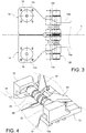
Figure 3 is a plan view of the tow portion of the foot ofFigures 1 and 2 ; -
Figure 4 is a perspective view showing a detail of a stiffness adjustment device of the foot ofFigures 1 and 2 ; -
Figures 5 and 6 are a perspective view and a axial section view, respectively, of the roller assembly of the stiffness adjustment device of the foot ofFigures 1 and 2 ; -
Figure 7 is an axial section view showing how the roller assembly is constrained to a support base of the foot ofFigures 1 and 2 ; -
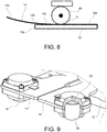
Figure 8 schematically shows a flexible toe of the foot ofFigures 1 and 2 in the deflected condition as a result of the application of an external force at the free end of the toe; and -
Figure 9 is a perspective view showing in detail the two flexible toes (one partially cut away) of the foot ofFigures 1 and 2 . - With reference first to
Figures 1 and 2 , a foot for a humanoid robot is generally indicated 10. Thefoot 10 basically comprises afoot base 12 made as a rigid body and at least one leaf spring 14 (in the illustrated embodiment, two leaf springs) acting as flexible toes of the foot. Theleaf springs 14 are attached with rear ends thereof to thefoot base 12 and extend forwards from the latter in a cantilevered fashion. Eachleaf spring 14 carries at a free end thereof a respectivefront contact member 16 for contact with the ground. Arear contact member 18 is also provided for and is attached to the rear end of thefoot base 12. - As shown in
figure 9 , each of thefront contact members 16 comprises arubber ball 20 and apressure sensor 22 for measuring the pressure applied to therubber ball 20. The same applies to therear contact member 18, which also comprises a rubber ball 24 (Figure 2 ) and a pressure sensor (not shown) for measuring the pressure applied to therubber ball 24. - With reference in particular to
Figure 3 , theleaf springs 14 are shaped and mounted symmetrically on thefoot base 12 with respect to a longitudinal axis x of thefoot 10. Eachleaf spring 14 comprises arear portion 14a rigidly connected to thefoot base 12, afront portion 14b projecting from afront edge 12a of thefoot base 12 and anintermediate portion 14c interposed between therear portion 14a and thefront portion 14b. Thefront contact members 16 are mounted on thefront portions 14b of therespective leaf springs 14. As schematically shown inFigure 8 , theintermediate portion 14c extends above an upperflat surface 12b of thefoot base 12 and is not attached to thefoot base 12 so as to be free to deflect, along with thefront portion 14b, as a result of the application of an external force F onto therespective leaf spring 14. Theleaf springs 14 are deflectable independently of each other, which is particularly useful when the foot is placed on different surface levels. Theleaf springs 14 are made for example of titanium, but may of course be made of any other suitable material. - The stiffness K of the
leaf spring 14 is given by
- The
foot 10 further comprises a stiffness adjustment device, generally indicated 26, for actively adjusting the stiffness K of theleaf springs 14 by varying the spring length l. - The
stiffness adjustment device 26 comprises first of all aroller assembly 28 which is held in contact with theleaf springs 14, in particular with theintermediate portions 14c thereof, so as to press theleaf springs 14 against the upperflat surface 12b of thefoot base 12. Theroller assembly 28 is freely rotatable about an axis of rotation y extending in the transverse direction, i.e. in a horizontal direction perpendicular to the longitudinal axis x. Moreover, theroller assembly 28 is movable in the longitudinal direction x relative to theleaf springs 14 so as to vary the point of contact P between theroller assembly 28 and theleaf springs 14. To this end, theroller assembly 28 is guided at its end portions by a pair ofguide members 32 mounted on the foot base 12 (Figure 4 ). As theroller assembly 28, and therefore its point of contact P with theleaf springs 14, moves in the longitudinal direction x, the spring length l also varies, thereby resulting in a change of the stiffness K of thesprings 14 according to equation (1). Indicating s the longitudinal position of the point of contact P, with s = 0 when the spring length l reaches its maximum value L and with s = s max when the spring length l reaches its minimum value (seeFigure 3 ), the spring length l is given by:
- The
stiffness adjustment device 26 further comprises anactuation unit 34 arranged to control the movement of theroller assembly 28 in the longitudinal direction x. In the proposed embodiment, theactuation unit 34 comprises arotary actuator 36, for example an electric motor, and a crank mechanism arranged to convert the rotary motion generated by therotary actuator 36 about an axis of rotation y1 parallel to the axis of rotation y of theroller assembly 28 into the translational motion of theroller assembly 28 along the longitudinal axis x. The crank mechanism comprises for example a pair ofcranks 38, which are arranged to be driven by therotary actuator 36 to rotate about the axis of rotation y1, and a pair of connectingrods 40, each of which is hinged at a first end thereof to arespective crank 38 and at the opposite end to theroller assembly 28. - Preferably, the
leaf springs 14 are shaped in such a manner that their width at the point of contact P does not remain constant, but changes, as the point of contact P moves in the longitudinal direction x as a result of the movement of theroller assembly 28 controlled by theactuation unit 34. In such a case, therefore, the stiffness K of theleaf springs 14 changes with the longitudinal position s of the point of contact P not only because the spring length l changes, but also because the spring width w changes. In the proposed embodiment, eachleaf spring 14 has an isosceles trapezoid shape in the portion where the point of contact P moves, whereby the spring width w linearly varies with the longitudinal position s of the point of contact P between a maximum value w 1 and a minimum value w 2 according to the following equation:
- In this case, therefore, the stiffness K of each
leaf spring 14 varies with the longitudinal position s of the point of contact P as follows:
- Since the spring width w increases with the longitudinal position s of the point of contact P, the rate of increase in the stiffness K is larger than would be the case with a constant spring width. A larger range of stiffness values is thus obtained compared to the case where the spring width is constant.
- Naturally, other shapes of the
leaf springs 14, and therefore other laws of variation of the stiffness K as a function of the longitudinal position s of the point of contact P, may be envisaged. - With reference now to
Figures 5 to 7 , the structure of theroller assembly 28 will be described in detail. According to the proposed embodiment, theroller assembly 28 comprises three rotating elements, namely twoouter elements 42 and amiddle element 44, which are rotatable independently of each other about the axis of rotation y. Providing separate rotating elements (in the present case, three elements) which rotate independently of each other about the same axis of rotation allows to minimize the frictional torques acting on theroller assembly 28. Preferably, each of the twoouter elements 42 has acylindrical body 42a in contact with its lateral surface on arespective leaf spring 14 and ashaft 42b projecting axially from thecylindrical body 42a. The twoouter elements 42 are arranged with theirshafts 42b facing each other, i.e. facing towards the centre of theroller assembly 28. Themiddle element 44 is made as a hollow cylindrical body which is rotatably supported on theshafts 42b of the twoouter elements 42 and is in contact with its lateral surface on both the leaf springs 14. Themiddle element 44 has acircumferential groove 46 extending throughout the lateral surface of that element. In the groove 46 aprotrusion 48 engages, which is formed by thefoot base 12 and extends along the longitudinal axis x to mechanically constrain theroller assembly 28 to move along this axis. As can be seen in particular inFigure 6 , the connectingrods 40 of the crank mechanism ofstiffness adjustment device 26 are hinged to theshafts 42b of the twoouter elements 42 of theroller assembly 28. Theroller assembly 28 further comprises a pair ofcam followers 50 which are rotatably mounted at the outer ends of the twoouter elements 42 and engage each with a respective one of theguide members 32 to ensure that the threerotating elements roller assembly 28 are held in contact with the leaf springs 14. - As is clear from the above description, the present inventions provides a simple and compact mechanism for actively varying the stiffness of a flexible toe of a humanoid robot foot, thus allowing to change the stiffness of the flexible toes depending for example on the characteristics of the terrain and hence to improve the ability of the robot to walk on uneven terrains.
- Naturally, the principle of the invention remaining unchanged, the embodiments and the constructional details may vary widely from those described and illustrated purely by way of non-limiting example, without thereby departing from the scope of the invention as defined in the appended claims.
- The following example is given as background art, and is not belonging to the invention. It is related to an active variable stiffness mechanism for actively changing the stiffness of at least one flexible member made as a leaf spring, wherein the at least one leaf spring is mounted on a support base of the mechanism and has a rear portion rigidly connected to a flat surface of the support base, a front portion projecting from the support base and an intermediate portion which is not rigidly connected to the support base and is therefore freely deflectable, along with the front portion, as a result of the application of an external force on the front portion, and wherein the mechanism further comprises a stiffness adjustment device including a roller assembly, which is held in contact with the intermediate portion of the at least one leaf spring and is movable relative to the at least one leaf spring along a longitudinal axis of the at least one leaf spring, and an actuation unit arranged to move the roller assembly, and hence the point of contact of the roller assembly with the at least one leaf spring, thereby varying the length of the cantilevered portion of the at least one leaf spring, and hence the stiffness of the at least one leaf spring. More specifically, the invention also relates to a mechanism of the above-mentioned type, wherein the intermediate portion of the at least one leaf spring is shaped such that its width at the point of contact with the roller assembly varies depending on the position of the roller assembly.
Claims (10)
- Humanoid robot foot (10) comprising
a foot base (12),
at least one leaf spring (14) acting as flexible toe of the foot, said at least one leaf spring (14) having a rear portion (14a) rigidly connected to a flat surface (12b) of the foot base (12), a front portion (14b) projecting from the foot base (12) and an intermediate portion (14c) which is not rigidly connected to the foot base (12) and is therefore freely deflectable, along with the front portion (14b), as a result of the application of an external force on the front portion (14b), and
a stiffness adjustment device (26) for actively changing the stiffness (K) of said at least one leaf spring (14),
wherein the stiffness adjustment device (26) comprises a roller assembly (28), which is held in contact with the intermediate portion (14c) of said at least one leaf spring (14) and is movable relative to said at least one leaf spring (14) along a longitudinal axis (x) of said at least one leaf spring (14), and an actuation unit (34) arranged to move the roller assembly (28), and hence the point of contact (P) of the roller assembly (28) with said at least one leaf spring (14), thereby varying the length (l) of the cantilevered portion of said at least one leaf spring (14), and hence the stiffness (K) of said at least one leaf spring (14). - Foot according to claim 1, wherein the intermediate portion (14c) of said at least one leaf spring (14) is shaped such that its width (w) at the point of contact (P) with the roller assembly (28) varies depending on the position (s) of the roller assembly (28).
- Foot according to claim 2, wherein the width (w) of the intermediate portion (14c) of said at least one leaf spring (14) at the point of contact (P) with the roller assembly (28) varies linearly with the position (s) of the roller assembly (28).
- Foot according to claim 2 or claim 3, wherein the width (w) of the intermediate portion (14c) of said at least one leaf spring (14) at the point of contact (P) with the roller assembly (28) increases as the distance of the point of contact (P) from the front portion (14b) of said at least one leaf spring (14) decreases.
- Foot according to any of the preceding claims, further comprising guide members (32) engaging end portions (50) of the roller assembly (28) to guide the roller assembly (28) along said longitudinal axis (x) and hold the roller assembly (28) in contact with the intermediate portion (14c) of said at least one leaf spring (14).
- Foot according to any of the preceding claims, wherein the roller assembly (28) is freely rotatable about an axis of rotation (y) extending perpendicular to said longitudinal axis (x).
- Foot according to claim 6, wherein the roller assembly (28) comprises a plurality of rotating elements (42, 44) which are rotatable independently of each other about said axis of rotation (y).
- Foot according to claim 6 or claim 7, where the actuation unit (34) comprises a rotary actuator (36) and a crank mechanism (38, 40) arranged to convert a rotary motion generated by the rotary actuator (36) about an axis of rotation (y1) parallel to the axis of rotation (y) of the roller assembly (28) into a translational motion of the roller assembly (28) along said longitudinal axis (x).
- Foot according any of the preceding claims, wherein said at least one leaf spring (14) is provided, at its front portion (14b), with a front ground contact member (16), and wherein the foot (10) further comprises a rear ground contact member (18) mounted on the rear end of the foot base (12).
- Foot according to claim 9, wherein each of said front and rear ground contact members (16, 18) comprises a rubber ball (20, 24) and a pressure sensor (22) for measuring the pressure applied to the rubber ball (20, 24).
Applications Claiming Priority (2)
| Application Number | Priority Date | Filing Date | Title |
|---|---|---|---|
| ITUB2015A005199A ITUB20155199A1 (en) | 2015-10-21 | 2015-10-21 | Active rigidity variation device, particularly for anthropomorphic robot foot. |
| PCT/EP2016/075218 WO2017068037A1 (en) | 2015-10-21 | 2016-10-20 | Humanoid robot foot comprising an active variable stiffness mechanism |
Publications (2)
| Publication Number | Publication Date |
|---|---|
| EP3365144A1 EP3365144A1 (en) | 2018-08-29 |
| EP3365144B1 true EP3365144B1 (en) | 2019-12-04 |
Family
ID=55085842
Family Applications (1)
| Application Number | Title | Priority Date | Filing Date |
|---|---|---|---|
| EP16794224.2A Active EP3365144B1 (en) | 2015-10-21 | 2016-10-20 | Humanoid robot foot comprising an active variable stiffness mechanism |
Country Status (4)
| Country | Link |
|---|---|
| US (1) | US10603803B2 (en) |
| EP (1) | EP3365144B1 (en) |
| IT (1) | ITUB20155199A1 (en) |
| WO (1) | WO2017068037A1 (en) |
Families Citing this family (12)
| Publication number | Priority date | Publication date | Assignee | Title |
|---|---|---|---|---|
| US20180111275A1 (en) * | 2014-08-01 | 2018-04-26 | Kugar Inc. | Modular system for constructing robots |
| WO2019041077A1 (en) * | 2017-08-27 | 2019-03-07 | 刘哲 | Intelligent robot |
| CN108482510B (en) * | 2018-03-23 | 2019-10-18 | 吉林大学 | Kneeless underactuated bionic biped walking machine with auxiliary side swing mechanism |
| US12616589B2 (en) | 2020-08-31 | 2026-05-05 | Rehabilitation Institute Of Chicago | Systems and methods for an ankle prosthesis |
| CN112869778B (en) * | 2021-01-11 | 2022-04-15 | 北京航空航天大学 | Variable rigidity throat swab holder |
| CN112874655B (en) * | 2021-02-04 | 2021-12-24 | 北京理工大学 | Angle-controllable robot passive foot and robot applying same |
| CN113386877B (en) * | 2021-05-26 | 2022-06-10 | 武汉理工大学 | Robot large adhesive force foot with replaceable sole |
| CN113334360B (en) * | 2021-06-25 | 2022-04-26 | 北京航空航天大学 | A Reconfigurable Compact Variable Stiffness Actuator |
| CN115447691B (en) * | 2022-09-01 | 2023-06-02 | 南京信息工程大学 | A foot-end mechanism with variable stiffness |
| WO2025110062A1 (en) * | 2023-11-24 | 2025-05-30 | 株式会社ソニー・インタラクティブエンタテインメント | Robot foot part structure and robot |
| CN119503047B (en) * | 2024-11-18 | 2025-10-21 | 北京理工大学 | A humanoid robot and its knee joint with variable stiffness and variable reduction ratio functions |
| CN120816530B (en) * | 2025-09-19 | 2025-11-21 | 西北工业大学 | Two-degree-of-freedom flexible joint with variable rigidity |
Family Cites Families (7)
| Publication number | Priority date | Publication date | Assignee | Title |
|---|---|---|---|---|
| US5161631A (en) * | 1989-11-27 | 1992-11-10 | Uragami Fukashi | Suction device capable of moving along a surface |
| US6625846B2 (en) * | 1998-03-06 | 2003-09-30 | Shigeo Takizawa | Caster for robot |
| US20040064195A1 (en) * | 2002-07-15 | 2004-04-01 | Hugh Herr | Variable-mechanical-impedance artificial legs |
| US10080672B2 (en) * | 2005-03-31 | 2018-09-25 | Bionx Medical Technologies, Inc. | Hybrid terrain-adaptive lower-extremity systems |
| CN103057620B (en) | 2013-02-05 | 2016-08-31 | 武汉大学 | A kind of humanoid robot foot section structure based on modular array sensor |
| CN103753604B (en) * | 2013-12-27 | 2015-08-19 | 北京航空航天大学 | A kind of Modular Flexible jockey of dynamic adjustment rigidity |
| CN103753064B (en) | 2013-12-31 | 2015-08-26 | 沪东重机有限公司 | A kind of assembly technique of marine diesel frame beam part |
-
2015
- 2015-10-21 IT ITUB2015A005199A patent/ITUB20155199A1/en unknown
-
2016
- 2016-10-20 EP EP16794224.2A patent/EP3365144B1/en active Active
- 2016-10-20 WO PCT/EP2016/075218 patent/WO2017068037A1/en not_active Ceased
- 2016-10-20 US US15/769,803 patent/US10603803B2/en active Active
Non-Patent Citations (1)
| Title |
|---|
| None * |
Also Published As
| Publication number | Publication date |
|---|---|
| WO2017068037A1 (en) | 2017-04-27 |
| EP3365144A1 (en) | 2018-08-29 |
| ITUB20155199A1 (en) | 2017-04-21 |
| US20180311837A1 (en) | 2018-11-01 |
| US10603803B2 (en) | 2020-03-31 |
Similar Documents
| Publication | Publication Date | Title |
|---|---|---|
| US10603803B2 (en) | Humanoid robot foot comprising an active variable stiffness mechanism | |
| US20230310181A1 (en) | Knee joint | |
| US12245955B2 (en) | Prosthetic device and method with compliant linking member and actuating linking member | |
| US10449105B2 (en) | System and method of bidirectional compliant joint torque actuation | |
| KR101283143B1 (en) | Knee Joint Assistive Device | |
| CN101460118B (en) | Walk assistance device | |
| CN103099691B (en) | Two-degree-of-freedom exoskeleton ankle joint mechanism | |
| KR101794703B1 (en) | A wearable hand rehabilitation system | |
| KR101184547B1 (en) | Knee joint assistive device having length variable mechanism | |
| EP3322395B1 (en) | Foot for a robotic exoskeleton for assisted walking of persons suffering from locomotor disorders | |
| CN102397118B (en) | Bionic ankle joint | |
| EP2702963A1 (en) | Powered prosthesis with serial and/or parallel compliance | |
| KR101983377B1 (en) | Motion assist apparatus | |
| CN110430841A (en) | A kind of foot prosthesis including buffer element | |
| KR20190100566A (en) | Motion assistance apparatus | |
| JP2014097550A (en) | Rigidity variable driving device and joint driving mechanism | |
| JP2016039857A (en) | Walking machine | |
| KR20200074841A (en) | A Prosthetic Leg | |
| JP2014097549A (en) | Rigidity variable driving device and joint driving mechanism | |
| KR20190014448A (en) | Motion assistance apparatus | |
| US20250242485A1 (en) | Variable stiffness actuator | |
| US20260091261A1 (en) | Adjustable surface stiffness treadmill | |
| JP6083502B2 (en) | Concise humanoid foot structure | |
| KR102894922B1 (en) | Wearable ankle joint motion assist device | |
| US20260060874A1 (en) | Semi passive joint exoskeleton |
Legal Events
| Date | Code | Title | Description |
|---|---|---|---|
| STAA | Information on the status of an ep patent application or granted ep patent |
Free format text: STATUS: UNKNOWN |
|
| STAA | Information on the status of an ep patent application or granted ep patent |
Free format text: STATUS: THE INTERNATIONAL PUBLICATION HAS BEEN MADE |
|
| PUAI | Public reference made under article 153(3) epc to a published international application that has entered the european phase |
Free format text: ORIGINAL CODE: 0009012 |
|
| STAA | Information on the status of an ep patent application or granted ep patent |
Free format text: STATUS: REQUEST FOR EXAMINATION WAS MADE |
|
| 17P | Request for examination filed |
Effective date: 20180515 |
|
| AK | Designated contracting states |
Kind code of ref document: A1 Designated state(s): AL AT BE BG CH CY CZ DE DK EE ES FI FR GB GR HR HU IE IS IT LI LT LU LV MC MK MT NL NO PL PT RO RS SE SI SK SM TR |
|
| AX | Request for extension of the european patent |
Extension state: BA ME |
|
| DAV | Request for validation of the european patent (deleted) | ||
| DAX | Request for extension of the european patent (deleted) | ||
| RIC1 | Information provided on ipc code assigned before grant |
Ipc: B25J 19/02 20060101ALI20190509BHEP Ipc: B25J 19/00 20060101ALI20190509BHEP Ipc: B62D 57/032 20060101ALI20190509BHEP Ipc: B25J 19/06 20060101AFI20190509BHEP |
|
| GRAP | Despatch of communication of intention to grant a patent |
Free format text: ORIGINAL CODE: EPIDOSNIGR1 |
|
| STAA | Information on the status of an ep patent application or granted ep patent |
Free format text: STATUS: GRANT OF PATENT IS INTENDED |
|
| INTG | Intention to grant announced |
Effective date: 20190614 |
|
| GRAS | Grant fee paid |
Free format text: ORIGINAL CODE: EPIDOSNIGR3 |
|
| GRAA | (expected) grant |
Free format text: ORIGINAL CODE: 0009210 |
|
| STAA | Information on the status of an ep patent application or granted ep patent |
Free format text: STATUS: THE PATENT HAS BEEN GRANTED |
|
| AK | Designated contracting states |
Kind code of ref document: B1 Designated state(s): AL AT BE BG CH CY CZ DE DK EE ES FI FR GB GR HR HU IE IS IT LI LT LU LV MC MK MT NL NO PL PT RO RS SE SI SK SM TR |
|
| REG | Reference to a national code |
Ref country code: GB Ref legal event code: FG4D |
|
| REG | Reference to a national code |
Ref country code: CH Ref legal event code: EP |
|
| REG | Reference to a national code |
Ref country code: AT Ref legal event code: REF Ref document number: 1208803 Country of ref document: AT Kind code of ref document: T Effective date: 20191215 |
|
| REG | Reference to a national code |
Ref country code: DE Ref legal event code: R096 Ref document number: 602016025716 Country of ref document: DE |
|
| REG | Reference to a national code |
Ref country code: IE Ref legal event code: FG4D |
|
| REG | Reference to a national code |
Ref country code: NL Ref legal event code: MP Effective date: 20191204 |
|
| REG | Reference to a national code |
Ref country code: LT Ref legal event code: MG4D |
|
| PG25 | Lapsed in a contracting state [announced via postgrant information from national office to epo] |
Ref country code: GR Free format text: LAPSE BECAUSE OF FAILURE TO SUBMIT A TRANSLATION OF THE DESCRIPTION OR TO PAY THE FEE WITHIN THE PRESCRIBED TIME-LIMIT Effective date: 20200305 Ref country code: LT Free format text: LAPSE BECAUSE OF FAILURE TO SUBMIT A TRANSLATION OF THE DESCRIPTION OR TO PAY THE FEE WITHIN THE PRESCRIBED TIME-LIMIT Effective date: 20191204 Ref country code: LV Free format text: LAPSE BECAUSE OF FAILURE TO SUBMIT A TRANSLATION OF THE DESCRIPTION OR TO PAY THE FEE WITHIN THE PRESCRIBED TIME-LIMIT Effective date: 20191204 Ref country code: SE Free format text: LAPSE BECAUSE OF FAILURE TO SUBMIT A TRANSLATION OF THE DESCRIPTION OR TO PAY THE FEE WITHIN THE PRESCRIBED TIME-LIMIT Effective date: 20191204 Ref country code: NO Free format text: LAPSE BECAUSE OF FAILURE TO SUBMIT A TRANSLATION OF THE DESCRIPTION OR TO PAY THE FEE WITHIN THE PRESCRIBED TIME-LIMIT Effective date: 20200304 Ref country code: FI Free format text: LAPSE BECAUSE OF FAILURE TO SUBMIT A TRANSLATION OF THE DESCRIPTION OR TO PAY THE FEE WITHIN THE PRESCRIBED TIME-LIMIT Effective date: 20191204 Ref country code: BG Free format text: LAPSE BECAUSE OF FAILURE TO SUBMIT A TRANSLATION OF THE DESCRIPTION OR TO PAY THE FEE WITHIN THE PRESCRIBED TIME-LIMIT Effective date: 20200304 |
|
| PG25 | Lapsed in a contracting state [announced via postgrant information from national office to epo] |
Ref country code: RS Free format text: LAPSE BECAUSE OF FAILURE TO SUBMIT A TRANSLATION OF THE DESCRIPTION OR TO PAY THE FEE WITHIN THE PRESCRIBED TIME-LIMIT Effective date: 20191204 Ref country code: HR Free format text: LAPSE BECAUSE OF FAILURE TO SUBMIT A TRANSLATION OF THE DESCRIPTION OR TO PAY THE FEE WITHIN THE PRESCRIBED TIME-LIMIT Effective date: 20191204 |
|
| PG25 | Lapsed in a contracting state [announced via postgrant information from national office to epo] |
Ref country code: AL Free format text: LAPSE BECAUSE OF FAILURE TO SUBMIT A TRANSLATION OF THE DESCRIPTION OR TO PAY THE FEE WITHIN THE PRESCRIBED TIME-LIMIT Effective date: 20191204 |
|
| PG25 | Lapsed in a contracting state [announced via postgrant information from national office to epo] |
Ref country code: EE Free format text: LAPSE BECAUSE OF FAILURE TO SUBMIT A TRANSLATION OF THE DESCRIPTION OR TO PAY THE FEE WITHIN THE PRESCRIBED TIME-LIMIT Effective date: 20191204 Ref country code: CZ Free format text: LAPSE BECAUSE OF FAILURE TO SUBMIT A TRANSLATION OF THE DESCRIPTION OR TO PAY THE FEE WITHIN THE PRESCRIBED TIME-LIMIT Effective date: 20191204 Ref country code: PT Free format text: LAPSE BECAUSE OF FAILURE TO SUBMIT A TRANSLATION OF THE DESCRIPTION OR TO PAY THE FEE WITHIN THE PRESCRIBED TIME-LIMIT Effective date: 20200429 Ref country code: ES Free format text: LAPSE BECAUSE OF FAILURE TO SUBMIT A TRANSLATION OF THE DESCRIPTION OR TO PAY THE FEE WITHIN THE PRESCRIBED TIME-LIMIT Effective date: 20191204 Ref country code: RO Free format text: LAPSE BECAUSE OF FAILURE TO SUBMIT A TRANSLATION OF THE DESCRIPTION OR TO PAY THE FEE WITHIN THE PRESCRIBED TIME-LIMIT Effective date: 20191204 Ref country code: NL Free format text: LAPSE BECAUSE OF FAILURE TO SUBMIT A TRANSLATION OF THE DESCRIPTION OR TO PAY THE FEE WITHIN THE PRESCRIBED TIME-LIMIT Effective date: 20191204 |
|
| PG25 | Lapsed in a contracting state [announced via postgrant information from national office to epo] |
Ref country code: SK Free format text: LAPSE BECAUSE OF FAILURE TO SUBMIT A TRANSLATION OF THE DESCRIPTION OR TO PAY THE FEE WITHIN THE PRESCRIBED TIME-LIMIT Effective date: 20191204 Ref country code: IS Free format text: LAPSE BECAUSE OF FAILURE TO SUBMIT A TRANSLATION OF THE DESCRIPTION OR TO PAY THE FEE WITHIN THE PRESCRIBED TIME-LIMIT Effective date: 20200404 Ref country code: SM Free format text: LAPSE BECAUSE OF FAILURE TO SUBMIT A TRANSLATION OF THE DESCRIPTION OR TO PAY THE FEE WITHIN THE PRESCRIBED TIME-LIMIT Effective date: 20191204 |
|
| REG | Reference to a national code |
Ref country code: DE Ref legal event code: R097 Ref document number: 602016025716 Country of ref document: DE |
|
| REG | Reference to a national code |
Ref country code: AT Ref legal event code: MK05 Ref document number: 1208803 Country of ref document: AT Kind code of ref document: T Effective date: 20191204 |
|
| PLBE | No opposition filed within time limit |
Free format text: ORIGINAL CODE: 0009261 |
|
| STAA | Information on the status of an ep patent application or granted ep patent |
Free format text: STATUS: NO OPPOSITION FILED WITHIN TIME LIMIT |
|
| PG25 | Lapsed in a contracting state [announced via postgrant information from national office to epo] |
Ref country code: DK Free format text: LAPSE BECAUSE OF FAILURE TO SUBMIT A TRANSLATION OF THE DESCRIPTION OR TO PAY THE FEE WITHIN THE PRESCRIBED TIME-LIMIT Effective date: 20191204 |
|
| 26N | No opposition filed |
Effective date: 20200907 |
|
| PG25 | Lapsed in a contracting state [announced via postgrant information from national office to epo] |
Ref country code: SI Free format text: LAPSE BECAUSE OF FAILURE TO SUBMIT A TRANSLATION OF THE DESCRIPTION OR TO PAY THE FEE WITHIN THE PRESCRIBED TIME-LIMIT Effective date: 20191204 Ref country code: PL Free format text: LAPSE BECAUSE OF FAILURE TO SUBMIT A TRANSLATION OF THE DESCRIPTION OR TO PAY THE FEE WITHIN THE PRESCRIBED TIME-LIMIT Effective date: 20191204 Ref country code: AT Free format text: LAPSE BECAUSE OF FAILURE TO SUBMIT A TRANSLATION OF THE DESCRIPTION OR TO PAY THE FEE WITHIN THE PRESCRIBED TIME-LIMIT Effective date: 20191204 |
|
| REG | Reference to a national code |
Ref country code: CH Ref legal event code: PL |
|
| PG25 | Lapsed in a contracting state [announced via postgrant information from national office to epo] |
Ref country code: LU Free format text: LAPSE BECAUSE OF NON-PAYMENT OF DUE FEES Effective date: 20201020 Ref country code: MC Free format text: LAPSE BECAUSE OF FAILURE TO SUBMIT A TRANSLATION OF THE DESCRIPTION OR TO PAY THE FEE WITHIN THE PRESCRIBED TIME-LIMIT Effective date: 20191204 |
|
| REG | Reference to a national code |
Ref country code: BE Ref legal event code: MM Effective date: 20201031 |
|
| PG25 | Lapsed in a contracting state [announced via postgrant information from national office to epo] |
Ref country code: LI Free format text: LAPSE BECAUSE OF NON-PAYMENT OF DUE FEES Effective date: 20201031 Ref country code: CH Free format text: LAPSE BECAUSE OF NON-PAYMENT OF DUE FEES Effective date: 20201031 Ref country code: BE Free format text: LAPSE BECAUSE OF NON-PAYMENT OF DUE FEES Effective date: 20201031 |
|
| PG25 | Lapsed in a contracting state [announced via postgrant information from national office to epo] |
Ref country code: IE Free format text: LAPSE BECAUSE OF NON-PAYMENT OF DUE FEES Effective date: 20201020 |
|
| PG25 | Lapsed in a contracting state [announced via postgrant information from national office to epo] |
Ref country code: TR Free format text: LAPSE BECAUSE OF FAILURE TO SUBMIT A TRANSLATION OF THE DESCRIPTION OR TO PAY THE FEE WITHIN THE PRESCRIBED TIME-LIMIT Effective date: 20191204 Ref country code: MT Free format text: LAPSE BECAUSE OF FAILURE TO SUBMIT A TRANSLATION OF THE DESCRIPTION OR TO PAY THE FEE WITHIN THE PRESCRIBED TIME-LIMIT Effective date: 20191204 Ref country code: CY Free format text: LAPSE BECAUSE OF FAILURE TO SUBMIT A TRANSLATION OF THE DESCRIPTION OR TO PAY THE FEE WITHIN THE PRESCRIBED TIME-LIMIT Effective date: 20191204 |
|
| PG25 | Lapsed in a contracting state [announced via postgrant information from national office to epo] |
Ref country code: MK Free format text: LAPSE BECAUSE OF FAILURE TO SUBMIT A TRANSLATION OF THE DESCRIPTION OR TO PAY THE FEE WITHIN THE PRESCRIBED TIME-LIMIT Effective date: 20191204 |
|
| REG | Reference to a national code |
Ref country code: DE Ref legal event code: R082 Ref document number: 602016025716 Country of ref document: DE Representative=s name: ALPSPITZ IP ALLGAYER UND PARTNER PATENTANWAELT, DE |
|
| P01 | Opt-out of the competence of the unified patent court (upc) registered |
Effective date: 20230811 |
|
| PGFP | Annual fee paid to national office [announced via postgrant information from national office to epo] |
Ref country code: FR Payment date: 20231124 Year of fee payment: 9 |
|
| PGFP | Annual fee paid to national office [announced via postgrant information from national office to epo] |
Ref country code: IT Payment date: 20240925 Year of fee payment: 9 |
|
| PGFP | Annual fee paid to national office [announced via postgrant information from national office to epo] |
Ref country code: DE Payment date: 20241015 Year of fee payment: 9 |
|
| PGFP | Annual fee paid to national office [announced via postgrant information from national office to epo] |
Ref country code: GB Payment date: 20241025 Year of fee payment: 9 |