EP3364652A1 - Display system and display method - Google Patents
Display system and display method Download PDFInfo
- Publication number
- EP3364652A1 EP3364652A1 EP17157226.6A EP17157226A EP3364652A1 EP 3364652 A1 EP3364652 A1 EP 3364652A1 EP 17157226 A EP17157226 A EP 17157226A EP 3364652 A1 EP3364652 A1 EP 3364652A1
- Authority
- EP
- European Patent Office
- Prior art keywords
- display
- display units
- dimensional object
- dimensional
- image
- Prior art date
- Legal status (The legal status is an assumption and is not a legal conclusion. Google has not performed a legal analysis and makes no representation as to the accuracy of the status listed.)
- Granted
Links
Images


Classifications
-
- H—ELECTRICITY
- H04—ELECTRIC COMMUNICATION TECHNIQUE
- H04N—PICTORIAL COMMUNICATION, e.g. TELEVISION
- H04N13/00—Stereoscopic video systems; Multi-view video systems; Details thereof
- H04N13/30—Image reproducers
- H04N13/388—Volumetric displays, i.e. systems where the image is built up from picture elements distributed through a volume
- H04N13/393—Volumetric displays, i.e. systems where the image is built up from picture elements distributed through a volume the volume being generated by a moving, e.g. vibrating or rotating, surface
-
- G—PHYSICS
- G02—OPTICS
- G02B—OPTICAL ELEMENTS, SYSTEMS OR APPARATUS
- G02B30/00—Optical systems or apparatus for producing three-dimensional [3D] effects, e.g. stereoscopic images
- G02B30/50—Optical systems or apparatus for producing three-dimensional [3D] effects, e.g. stereoscopic images the image being built up from image elements distributed over a three-dimensional [3D] volume, e.g. voxels
- G02B30/54—Optical systems or apparatus for producing three-dimensional [3D] effects, e.g. stereoscopic images the image being built up from image elements distributed over a three-dimensional [3D] volume, e.g. voxels the three-dimensional [3D] volume being generated by moving a two-dimensional [2D] surface, e.g. by vibrating or rotating the 2D surface
-
- H—ELECTRICITY
- H04—ELECTRIC COMMUNICATION TECHNIQUE
- H04N—PICTORIAL COMMUNICATION, e.g. TELEVISION
- H04N13/00—Stereoscopic video systems; Multi-view video systems; Details thereof
- H04N13/30—Image reproducers
- H04N13/366—Image reproducers using viewer tracking
- H04N13/383—Image reproducers using viewer tracking for tracking with gaze detection, i.e. detecting the lines of sight of the viewer's eyes
Definitions
- the invention relates to a display system and a corresponding display method.
- the present invention will mainly be described in conjunction with live display of moving three dimensional objects. It is however understood, that the present invention may also be used to display static content.
- the displaying of three dimensional content is generally used e.g. in computer animation or movie CGI effects. Until recently such three dimensional content was usually displayed on two dimensional display devices.
- Such three dimensional displays provide distinct images for the left and right eyes of the users and therefore create a three dimensional illusion for the users.
- Such displays are usually flat panel displays, like e.g. TV sets or cinema screens.
- the user must usually sit on a fixed or limited position in front of the screen to experience the three dimensional effect. Further, the user may not walk around the object.
- head mounted displays which while displaying a three dimensional image to the user also monitor any movement of the user.
- a corresponding PC may then provide the three dimensional content in real time.
- a user may e.g. walk around in a building or walk around objects.
- any of the known methods only provide illusions to the users, that either require specific positions or a dedicated hardware, like a headset.
- the present invention provides a display system with the features of claim 1 and a display method with the features of claim 9.
- the display system comprises a plurality of display units, a motion device, which is mechanically coupled to the display units and is configured to position the display units according to a shape of the three dimensional object, and an image controller, which is electronically coupled to the display units and is configured to display an image of the three dimensional object on the display units.
- a display method for displaying a three dimensional object comprises mechanically positioning a plurality display units according to a shape of the three dimensional object, electronically contacting the display units, and displaying an image of the three dimensional object on the display units.
- the present invention is based on the finding that traditional methods of displaying objects in three dimensions do not provide a satisfactory result and have very limited possibilities. For example it is not possible to walk around the object or touch the object.
- the present invention takes into account this deficiencies and provides a display system with display units that can each be positioned independently.
- the motion device may be any mechanical arrangement that allows individually moving and positioning the single display units.
- the motion device will therefore mimic the shape of the three dimensional object with the plurality of display units. That means that the motion device positions the single display units such that they follow the shape of the three dimensional object. Even without any image data showing on the display units, the shape of the three dimensional object will therefore be visible at least in an approximated form. It is understood, that the number and size of the display units determines the amount of details that may be formed by positioning the display units.
- the image controller will then provide respective image data to the display units that is based on an image of the three dimensional object. However, the image controller will not display an image of the three dimensional object on every display unit. Instead, the image controller will only display sections of the image on the display units.
- the image controller will choose the section of the image that is displayed on a single display unit according to the position of the display unit.
- the section that is displayed on a display unit will therefore correspond to the section of the three dimensional object that is represented by the position and size of the respective display unit.
- the object is formed or reproduced at least approximately in reality to improve the visual three dimensional effect and furthermore a user may touch the object or the user may walk around the object.
- the display system may comprise a motion controller, which may be configured to adapt the position and/or orientation of the single display units by controlling the motion device based on a three dimensional model of the three dimensional object.
- the shape of the three dimensional object may easily be rebuilt locally with the single display units.
- the display units may e.g. be positioned such that the normal of the plane of the display unit is parallel or lies on the normal of the respective section of the three dimensional model.
- the motion device may e.g. comprise a plurality of single arm-like arrangements that each carry a single or a plurality of display units. Further, every display unit may be pivotably mounted on the respective arm. Such arms may e.g. be provided on a pole or rod and may therefore cover a 360° angle around the pole.
- Such arms may also be mounted on a wall.
- the display unit will then only show one side of the three dimensional object, e.g. as a kind of relief.
- the motion device may also comprise a matrix of horizontally and vertically movable slides or the like.
- the above mentioned arms may be mounted on such slides.
- the motion controller may be configured to calculate for a section of the three dimensional model that corresponds to the section represented by a respective one of the display units an average orientation and control the motion device to position the respective display unit accordingly.
- Every display unit will represent and display a specific section of the three dimensional object. It is obvious that the smaller the display units are chosen the more details may be modelled. However, it may become impractical to move a large number of display units if the display units become too small. Therefore, every display unit may represent a predefined section of the three dimensional object.
- display units with a width of 4,9 inch and a height of 3,0 inch may be used.
- Such display units may, without any scaling by the image controller, represent a section of the surface of the three dimensional object of the same size.
- Calculating a mean orientation of the respective section will provide an approximation of the orientation of the entire section of the three dimensional object that will be shown on the respective display unit. If only one surface point of the three dimensional model would be used to determine the orientation of the respective display unit, the orientation of that surface point might strongly deviate from such a mean value.
- the display units may comprise display units of different sizes. If display units of different sizes are used, more detailed regions of the three dimensional object may be represented by smaller display units and regions of less details may be represented by larger display units.
- larger display units may be used to represent the legs, the arms or the torso of a person.
- Smaller display units may in contrast be used to represent the face, hands or any other detailed section of the person.
- the image controller may be configured to display on each one of the display units a respective section of the image of the three dimensional object that corresponds to the position of the respective display unit.
- the display controller may be in communication with the motion device and know the sizes and orientations of the single display units.
- the image of the three dimensional object may be provided as a texture for the three dimensional model.
- the image controller may therefore cut out from the complete image or texture of the three dimensional object the respective section of the texture for each display unit and display that section on the respective display unit.
- the image controller may also use the three dimensional model and display the section of the image of the three dimensional object as an overlay over the respective section of the three dimensional model.
- the image controller may further use additional techniques like e.g. displacement mapping or the like to enhance the quality of displaying the three dimensional object.
- the image controller may perform some kind of three dimensional rendering and that not only flat images may be displayed on the single display units.
- the display system may comprise a tracking device that may be configured to track a position of eyes of a user of the display system, wherein the image controller may be configured to adapt the displayed image for every display unit according to the position of the user's eyes.
- the image controller may e.g. render the section of the three dimensional model and the respective image according to a viewing direction of the user for every single display unit. This will further improve the quality of the displayed object and provide a more realistic display.
- the display system may comprise a memory configured to store a plurality of three dimensional models and/or images of the respective three dimensional objects.
- the three dimensional models are pre-stored in the display system, there is no need to transmit them every time an object should be displayed.
- the stored three dimensional models can then simply be loaded and the respective image may be displayed.
- the display system may comprise a communication interface configured to receive the three dimensional model and/or the image of the three dimensional object.
- a communication interface data of the three dimensional object e.g. the three dimensional model and the respective images, may be received in real time. This will allow e.g. to perform live video calls or any other type of live transmission with the display system.
- the display system may comprise a three dimensional scanner, which may be configured to scan a further three dimensional object and provide a respective further three dimensional model.
- the display system may comprise a camera system, which may be configured to record a further image of the further three dimensional object.
- the display system may easily be extended to serve as a bi-directional conferencing system by providing two display systems in two remote places, and every display system with a three dimensional scanner and/or a camera.
- the scanned data of a local user may then be transmitted via a data network to the other display system and may there be displayed to the remote user and vice versa.
- Fig. 1 shows a block diagram of a display system 100.
- the display system 100 can be used to display or better recreate the three dimensional object 150.
- the display system 100 comprises a plurality of display units 101, 102, 103, of which only three are exemplarily shown. It is understood that any number of display units may be provided.
- the display units 101, 102, 103 are mechanically coupled to a motion device 104 and are further electrically coupled to an image controller 105.
- the motion device 104 comprises movement arms 106, 107, 108 for the display units 101, 102, 103.
- the movement arms 106, 107, 108 are capable of moving up and down and extend in length.
- the display units 101, 102, 103 may be pivotably moveable on the movement arms 106, 107, 108 with the help of a ball or spherical joint.
- the motion device 104 may e.g. comprise electric motors (not explicitly shown) and respective motor drivers to move the movement arms 106, 107, 108 and position the display units 101, 102, 103 accordingly.
- the display system 100 further comprises an optional memory 109 and an optional communication interface 110.
- the memory 109 and the communication interface 110 may be used to provide the motion device 104 and the image controller 105 with a three dimensional model 111 of the three dimensional object 150 and with an image 112 of the three dimensional object 150. It is understood, that any other means for providing the three dimensional model 111 and the image 112 may be used, like e.g. a USB stick.
- a motion controller 114 of the motion device 104 can move the single display units 101, 102, 103 according to the shape of the three dimensional object 150.
- the single display units 101, 102, 103 will therefore mimic or recreate the outer contour of the three dimensional object 150.
- the motion controller 114 may e.g. calculate for a section of the three dimensional model 111 that corresponds to the section represented by a respective one of the display units 101, 102, 103 an average orientation and control position of the respective display unit 101, 102, 103 accordingly.
- the image controller 105 may provide the display units 101, 102, 103 with the respective sections of the image 112, which represent the section of the original three dimensional object 150 that is represented by the respective display units 101, 102, 103. That means that every one of the display units 101, 102, 103 will show a section of an image of the three dimensional object 150 that exactly matches the position of the respective display units 101, 102, 103 when projected onto the three dimensional object 150.
- the display system 100 further comprises an optional tracking device 113.
- the tracking device 113 may track a position of eyes of a user of the display system 100.
- the image controller 105 may then adapt the displayed image 112 for every display unit 101, 102, 103 according to the position of the user's eyes.
- the three dimensional object 150 may be any static or moving three dimensional object. Further, movements of the three dimensional object 150 may be transmitted via the communication interface 110 in real time, i.e. as fast as possible, from a position where the three dimensional object 150 may be scanned to the position where the display system 100 is located. This allows using the display system 100 to perform video calls.
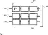
- Fig. 2 shows a block diagram of a display system 200.
- the display system 200 may comprise the same elements as the display system 100.
- the focus lies on explaining an alternative motion device 204.
- the display system 200 is just exemplarily shown with nine display units 201, 202, of which for sake of clarity only the first and the last are provided with reference signs.
- the motion device 204 comprises three movement arms 206, 207, 208, which are parallel to each other and each carry a plurality of display units 201, 202.
- the movement arms 206, 207, 208 themselves may move upwards and downwards. It is understood, that such a movement of the movement arms 206, 207, 208 will also move the respective display units 201, 202 upwards or downwards.
- the display units 201, 202 may move sideways on the movement arms 206, 207, 208. This already allows to move the display units 201, 202 in two dimensions. However, the display units 201, 202 may further be pivotably mounted and may therefore be tilted in any direction.
- a relief-like 3D display of a three dimensional object is possible. It is however understood that the arrangement shown in Fig. 2 may be just a subsection of the display system 200. In one example, a plurality of arrangements as shown in Fig. 2 may e.g. be provided side by side in a ring or hexagon like arrangement. This would allow displaying a real three dimensional object from all sides.
- Fig. 3 shows a block diagram of a display system 300.
- the display system 300 provides an alternative mechanical arrangement for moving the single display units 301, 302, 303, 314, 315.
- some of the display units have been omitted, such that the mechanical structure beneath the display units becomes visible. It is however, understood, that the display system 300 may comprise further display units that cover the mechanical arrangements.
- the display units 301, 302, 303, 314, 315 are each supported by a mechanical three joint arm 306, 307. Every one of the arms has a joint 320, 323 coupled to the respective display unit 301, 302, 303, 314, 315, a center joint 321, 324, and a joint 322, 325 that couples the arm to the motion device 304.
- the single arms 306, 307 may also be moveable up and down on the motion device 304 or rotate around the motion device 304.
- the joints 320 - 325 may be ball or spherical joints and may therefore allow a pivot motion of the display units 301, 302, 303, 314, 315.
- display system 300 allows completely recreating three dimensional objects without being limited to only one side.
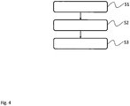
- Fig. 4 shows a block diagram of an embodiment of a display method for displaying a three dimensional object 150.
- the display method comprises mechanically positioning S1 a plurality display units 101 - 103, 201, 202, 301 -303, 314, 315 according to a shape of the three dimensional object 150.
- the method also comprises electronically contacting S2 the display units (101 - 103, 201, 202, 301 - 303, 314, 315, and displaying S3 an image 112 of the three dimensional object 150 on the display units 101 - 103, 201, 202, 301 - 303, 314, 315.
- the method may e.g. be used to recreate the contour or shape of the three dimensional object 150 with the display units 101 - 103, 201, 202, 301 - 303, 314, 315. This will allow a user to walk around the recreated three dimensional object 150 and touch the recreated three dimensional object 150.
- the display units 101 - 103, 201, 202, 301 - 303, 314, 315 may comprise display units 101 - 103, 201, 202, 301 - 303, 314, 315 of different sizes.
- the method may also comprise storing a plurality of three dimensional models 111 and/or images 112 of the respective three dimensional objects 150. These three dimensional models 111 and/or images 112 may then be used to recreate the respective three dimensional objects 150, even without an online data connection.
- the three dimensional model 111 and/or the image 112 of the three dimensional object 150 may also be received via a communication interface 110.
- the method may also comprise scanning a further three dimensional object, and provide a respective further three dimensional model 111, and recording an image of the further three dimensional object.
- a further three dimensional object may e.g. be a user that wants to perform a video chat.
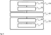
- Fig. 5 shows a block diagram of another embodiment of a display method.
- the display method of Fig. 5 is based on the display method of Fig. 4 .
- the step of mechanically positioning S1 comprises adapting S4 the position and/or orientation of the single display units 101 - 103, 201, 202, 301 - 303, 314, 315 based on a three dimensional model 111 of the three dimensional object 150. Further, mechanically positioning S1 comprises calculating S5 for a section of the three dimensional model 111 that corresponds to the section represented by a respective one of the display units 101 - 103, 201, 202, 301 - 303, 314, 315 an average orientation and positioning the respective display unit 101 - 103, 201, 202, 301 - 303, 314, 315 accordingly.
- displaying S3 comprises displaying S6 on each one of the display units 101 - 103, 201, 202, 301 - 303, 314, 315 a respective section of the image 112 of the three dimensional object 150 that corresponds to the position of the respective display unit 101 - 103, 201, 202, 301 - 303, 314, 315.
- displaying may comprise tracking S7 a position of eyes of a user, and adapting the displayed image 112 for every display unit 101 - 103, 201, 202, 301 - 303, 314, 315 according to the position of the user's eyes.
- the present invention provides a display system 100, 200, 300 for displaying a three dimensional object 150, the display system 100, 200, 300 comprising a plurality of display units 101 - 103, 201, 202, 301 - 303, 314, 315, a motion device 104, 204, 304, which is mechanically coupled to the display units 101 - 103, 201, 202, 301 - 303, 314, 315 and is configured to position the display units 101 - 103, 201, 202, 301 - 303, 314, 315 according to a shape of the three dimensional object 150, and an image controller 105, which is electronically coupled to the display units 101 - 103, 201, 202, 301 - 303, 314, 315 and is configured to display an image 112 of the three dimensional object 150 on the display units 101 - 103, 201, 202, 301 - 303, 314, 315.
- the present invention further provides a respective display method.
Landscapes
- Physics & Mathematics (AREA)
- General Physics & Mathematics (AREA)
- Optics & Photonics (AREA)
- Engineering & Computer Science (AREA)
- Multimedia (AREA)
- Signal Processing (AREA)
- Processing Or Creating Images (AREA)
- Stereoscopic And Panoramic Photography (AREA)
Abstract
Description
- The invention relates to a display system and a corresponding display method.
- The present invention will mainly be described in conjunction with live display of moving three dimensional objects. It is however understood, that the present invention may also be used to display static content.
- The displaying of three dimensional content is generally used e.g. in computer animation or movie CGI effects. Until recently such three dimensional content was usually displayed on two dimensional display devices.
- To increase immersion for the users, lately three dimensional displays have been developed. Such three dimensional displays provide distinct images for the left and right eyes of the users and therefore create a three dimensional illusion for the users.
- However, such displays are usually flat panel displays, like e.g. TV sets or cinema screens. The user must usually sit on a fixed or limited position in front of the screen to experience the three dimensional effect. Further, the user may not walk around the object.
- To further improve the user immersion, so called head mounted displays have been developed, which while displaying a three dimensional image to the user also monitor any movement of the user. A corresponding PC may then provide the three dimensional content in real time. A user may e.g. walk around in a building or walk around objects.
- However, any of the known methods only provide illusions to the users, that either require specific positions or a dedicated hardware, like a headset.
- Accordingly, there is a need for an improved three dimensional display.
- The present invention provides a display system with the features of
claim 1 and a display method with the features of claim 9. - Therefore a display system for displaying a three dimensional object is provided. The display system comprises a plurality of display units, a motion device, which is mechanically coupled to the display units and is configured to position the display units according to a shape of the three dimensional object, and an image controller, which is electronically coupled to the display units and is configured to display an image of the three dimensional object on the display units.
- Further, a display method for displaying a three dimensional object is provided. The display method comprises mechanically positioning a plurality display units according to a shape of the three dimensional object, electronically contacting the display units, and displaying an image of the three dimensional object on the display units.
- The present invention is based on the finding that traditional methods of displaying objects in three dimensions do not provide a satisfactory result and have very limited possibilities. For example it is not possible to walk around the object or touch the object.
- The present invention takes into account this deficiencies and provides a display system with display units that can each be positioned independently. The motion device may be any mechanical arrangement that allows individually moving and positioning the single display units.
- The motion device will therefore mimic the shape of the three dimensional object with the plurality of display units. That means that the motion device positions the single display units such that they follow the shape of the three dimensional object. Even without any image data showing on the display units, the shape of the three dimensional object will therefore be visible at least in an approximated form. It is understood, that the number and size of the display units determines the amount of details that may be formed by positioning the display units.
- After the single display units are positioned by the motion device, the image controller will then provide respective image data to the display units that is based on an image of the three dimensional object. However, the image controller will not display an image of the three dimensional object on every display unit. Instead, the image controller will only display sections of the image on the display units.
- The image controller will choose the section of the image that is displayed on a single display unit according to the position of the display unit. The section that is displayed on a display unit will therefore correspond to the section of the three dimensional object that is represented by the position and size of the respective display unit.
- In contrast to common 3D displays with the present invention the object is formed or reproduced at least approximately in reality to improve the visual three dimensional effect and furthermore a user may touch the object or the user may walk around the object.
- Further embodiments of the present invention are subject of the further subclaims and of the following description, referring to the drawings.
- In one embodiment, the display system may comprise a motion controller, which may be configured to adapt the position and/or orientation of the single display units by controlling the motion device based on a three dimensional model of the three dimensional object.
- By moving the single display units according to a three dimensional model of the three dimensional object, the shape of the three dimensional object may easily be rebuilt locally with the single display units. The display units may e.g. be positioned such that the normal of the plane of the display unit is parallel or lies on the normal of the respective section of the three dimensional model.
- The motion device may e.g. comprise a plurality of single arm-like arrangements that each carry a single or a plurality of display units. Further, every display unit may be pivotably mounted on the respective arm. Such arms may e.g. be provided on a pole or rod and may therefore cover a 360° angle around the pole.
- However, such arms may also be mounted on a wall. In that case, the display unit will then only show one side of the three dimensional object, e.g. as a kind of relief.
- As an alternative, the motion device may also comprise a matrix of horizontally and vertically movable slides or the like. However, the above mentioned arms may be mounted on such slides.
- In one embodiment, the motion controller may be configured to calculate for a section of the three dimensional model that corresponds to the section represented by a respective one of the display units an average orientation and control the motion device to position the respective display unit accordingly.
- Every display unit will represent and display a specific section of the three dimensional object. It is obvious that the smaller the display units are chosen the more details may be modelled. However, it may become impractical to move a large number of display units if the display units become too small. Therefore, every display unit may represent a predefined section of the three dimensional object.
- For example display units with a width of 4,9 inch and a height of 3,0 inch may be used. Such display units may, without any scaling by the image controller, represent a section of the surface of the three dimensional object of the same size.
- Calculating a mean orientation of the respective section will provide an approximation of the orientation of the entire section of the three dimensional object that will be shown on the respective display unit. If only one surface point of the three dimensional model would be used to determine the orientation of the respective display unit, the orientation of that surface point might strongly deviate from such a mean value.
- In another embodiment, the display units may comprise display units of different sizes. If display units of different sizes are used, more detailed regions of the three dimensional object may be represented by smaller display units and regions of less details may be represented by larger display units.
- For example, larger display units may be used to represent the legs, the arms or the torso of a person. Smaller display units may in contrast be used to represent the face, hands or any other detailed section of the person.
- In one embodiment, the image controller may be configured to display on each one of the display units a respective section of the image of the three dimensional object that corresponds to the position of the respective display unit.
- The display controller may be in communication with the motion device and know the sizes and orientations of the single display units. At the same time, the image of the three dimensional object may be provided as a texture for the three dimensional model.
- The image controller may therefore cut out from the complete image or texture of the three dimensional object the respective section of the texture for each display unit and display that section on the respective display unit.
- The image controller may also use the three dimensional model and display the section of the image of the three dimensional object as an overlay over the respective section of the three dimensional model. The image controller may further use additional techniques like e.g. displacement mapping or the like to enhance the quality of displaying the three dimensional object.
- This means that the image controller may perform some kind of three dimensional rendering and that not only flat images may be displayed on the single display units.
- In one embodiment, the display system may comprise a tracking device that may be configured to track a position of eyes of a user of the display system, wherein the image controller may be configured to adapt the displayed image for every display unit according to the position of the user's eyes.
- The image controller may e.g. render the section of the three dimensional model and the respective image according to a viewing direction of the user for every single display unit. This will further improve the quality of the displayed object and provide a more realistic display.
- In one embodiment, the display system may comprise a memory configured to store a plurality of three dimensional models and/or images of the respective three dimensional objects.
- If the three dimensional models are pre-stored in the display system, there is no need to transmit them every time an object should be displayed. The stored three dimensional models can then simply be loaded and the respective image may be displayed.
- In another embodiment, the display system may comprise a communication interface configured to receive the three dimensional model and/or the image of the three dimensional object.
- With a communication interface data of the three dimensional object, e.g. the three dimensional model and the respective images, may be received in real time. This will allow e.g. to perform live video calls or any other type of live transmission with the display system.
- It is also possible to combine stored information with live information that is transmitted via the communication interface. It is possible for example to transmit only sections of the three dimensional object that change constantly. In an exemplary video conference, for example only live data regarding the face of the person that is performing the video conference may be transmitted, while the torso, arms and legs may be a standard male or female model, or any other avatar-like model, that is then combined with the live data.
- In one embodiment, the display system may comprise a three dimensional scanner, which may be configured to scan a further three dimensional object and provide a respective further three dimensional model. As an alternative or in addition the display system may comprise a camera system, which may be configured to record a further image of the further three dimensional object.
- The display system may easily be extended to serve as a bi-directional conferencing system by providing two display systems in two remote places, and every display system with a three dimensional scanner and/or a camera. The scanned data of a local user may then be transmitted via a data network to the other display system and may there be displayed to the remote user and vice versa.
- For a more complete understanding of the present invention and advantages thereof, reference is now made to the following description taken in conjunction with the accompanying drawings. The invention is explained in more detail below using exemplary embodiments which are specified in the schematic figures of the drawings, in which:
- Fig. 1
- shows a block diagram of an embodiment of a display system according to the present invention;
- Fig. 2
- shows a block diagram of another embodiment of a display system according to the present invention;
- Fig. 3
- shows a block diagram of another embodiment of a display system according to the present invention;
- Fig. 4
- shows a block diagram of an embodiment of a display method according to the present invention; and
- Fig. 5
- shows a block diagram of another embodiment of a display method according to the present invention.
- In the figures like reference signs denote like elements unless stated otherwise.
-
Fig. 1 shows a block diagram of adisplay system 100. Thedisplay system 100 can be used to display or better recreate the threedimensional object 150. Thedisplay system 100 comprises a plurality ofdisplay units - The
display units motion device 104 and are further electrically coupled to animage controller 105. Themotion device 104 comprisesmovement arms display units movement arms display units movement arms - The
motion device 104 may e.g. comprise electric motors (not explicitly shown) and respective motor drivers to move themovement arms display units - The
display system 100 further comprises anoptional memory 109 and anoptional communication interface 110. Thememory 109 and thecommunication interface 110 may be used to provide themotion device 104 and theimage controller 105 with a threedimensional model 111 of the threedimensional object 150 and with animage 112 of the threedimensional object 150. It is understood, that any other means for providing the threedimensional model 111 and theimage 112 may be used, like e.g. a USB stick. - After receiving the three
dimensional model 111, a motion controller 114 of themotion device 104 can move thesingle display units dimensional object 150. Thesingle display units dimensional object 150. The motion controller 114 may e.g. calculate for a section of the threedimensional model 111 that corresponds to the section represented by a respective one of thedisplay units respective display unit - At the same time the
image controller 105 may provide thedisplay units image 112, which represent the section of the original threedimensional object 150 that is represented by therespective display units display units dimensional object 150 that exactly matches the position of therespective display units dimensional object 150. - The
display system 100 further comprises anoptional tracking device 113. Thetracking device 113 may track a position of eyes of a user of thedisplay system 100. Theimage controller 105 may then adapt the displayedimage 112 for everydisplay unit - It is understood, that although shown as a vase, the three
dimensional object 150 may be any static or moving three dimensional object. Further, movements of the threedimensional object 150 may be transmitted via thecommunication interface 110 in real time, i.e. as fast as possible, from a position where the threedimensional object 150 may be scanned to the position where thedisplay system 100 is located. This allows using thedisplay system 100 to perform video calls. -
Fig. 2 shows a block diagram of adisplay system 200. Thedisplay system 200 may comprise the same elements as thedisplay system 100. InFig. 2 the focus lies on explaining analternative motion device 204. Thedisplay system 200 is just exemplarily shown with ninedisplay units - The
motion device 204 comprises threemovement arms display units movement arms movement arms respective display units - At the same time, the
display units movement arms display units display units - With the arrangement of
Fig. 2 a relief-like 3D display of a three dimensional object is possible. It is however understood that the arrangement shown inFig. 2 may be just a subsection of thedisplay system 200. In one example, a plurality of arrangements as shown inFig. 2 may e.g. be provided side by side in a ring or hexagon like arrangement. This would allow displaying a real three dimensional object from all sides. -
Fig. 3 shows a block diagram of adisplay system 300. Thedisplay system 300 provides an alternative mechanical arrangement for moving thesingle display units display system 300 may comprise further display units that cover the mechanical arrangements. - In the
display system 300 thedisplay units joint arm respective display unit motion device 304. - It is understood, that the arrangement is just exemplarily shown and that any other arrangement that allows the required movements is possible. The
single arms motion device 304 or rotate around themotion device 304. - The joints 320 - 325 may be ball or spherical joints and may therefore allow a pivot motion of the
display units - The arrangement shown regarding
display system 300 allows completely recreating three dimensional objects without being limited to only one side. - For sake of clarity the reference signs used above in conjunction with the apparatus-based figures will also be used below to explain the method-based figures.
-
Fig. 4 shows a block diagram of an embodiment of a display method for displaying a threedimensional object 150. - The display method comprises mechanically positioning S1 a plurality display units 101 - 103, 201, 202, 301 -303, 314, 315 according to a shape of the three
dimensional object 150. - The method also comprises electronically contacting S2 the display units (101 - 103, 201, 202, 301 - 303, 314, 315, and displaying S3 an
image 112 of the threedimensional object 150 on the display units 101 - 103, 201, 202, 301 - 303, 314, 315. - The method may e.g. be used to recreate the contour or shape of the three
dimensional object 150 with the display units 101 - 103, 201, 202, 301 - 303, 314, 315. This will allow a user to walk around the recreated threedimensional object 150 and touch the recreated threedimensional object 150. - It is understood, that the display units 101 - 103, 201, 202, 301 - 303, 314, 315 may comprise display units 101 - 103, 201, 202, 301 - 303, 314, 315 of different sizes.
- The method may also comprise storing a plurality of three
dimensional models 111 and/orimages 112 of the respective threedimensional objects 150. These threedimensional models 111 and/orimages 112 may then be used to recreate the respective threedimensional objects 150, even without an online data connection. - As an alternative or in addition, the three
dimensional model 111 and/or theimage 112 of the threedimensional object 150 may also be received via acommunication interface 110. - Further, if a bidirectional communication should be provided, the method may also comprise scanning a further three dimensional object, and provide a respective further three
dimensional model 111, and recording an image of the further three dimensional object. Such a further three dimensional object may e.g. be a user that wants to perform a video chat. -
Fig. 5 shows a block diagram of another embodiment of a display method. The display method ofFig. 5 is based on the display method ofFig. 4 . - However, the step of mechanically positioning S1 comprises adapting S4 the position and/or orientation of the single display units 101 - 103, 201, 202, 301 - 303, 314, 315 based on a three
dimensional model 111 of the threedimensional object 150. Further, mechanically positioning S1 comprises calculating S5 for a section of the threedimensional model 111 that corresponds to the section represented by a respective one of the display units 101 - 103, 201, 202, 301 - 303, 314, 315 an average orientation and positioning the respective display unit 101 - 103, 201, 202, 301 - 303, 314, 315 accordingly. - Further, displaying S3 comprises displaying S6 on each one of the display units 101 - 103, 201, 202, 301 - 303, 314, 315 a respective section of the
image 112 of the threedimensional object 150 that corresponds to the position of the respective display unit 101 - 103, 201, 202, 301 - 303, 314, 315. - Finally, displaying may comprise tracking S7 a position of eyes of a user, and adapting the displayed
image 112 for every display unit 101 - 103, 201, 202, 301 - 303, 314, 315 according to the position of the user's eyes. - Although specific embodiments have been illustrated and described herein, it will be appreciated by those of ordinary skill in the art that a variety of alternate and/or equivalent implementations exist. It should be appreciated that the exemplary embodiment or exemplary embodiments are only examples, and are not intended to limit the scope, applicability, or configuration in any way. Rather, the foregoing summary and detailed description will provide those skilled in the art with a convenient road map for implementing at least one exemplary embodiment, it being understood that various changes may be made in the function and arrangement of elements described in an exemplary embodiment without departing from the scope as set forth in the appended claims and their legal equivalents. Generally, this application is intended to cover any adaptations or variations of the specific embodiments discussed herein.
- The present invention provides a
display system dimensional object 150, thedisplay system motion device dimensional object 150, and animage controller 105, which is electronically coupled to the display units 101 - 103, 201, 202, 301 - 303, 314, 315 and is configured to display animage 112 of the threedimensional object 150 on the display units 101 - 103, 201, 202, 301 - 303, 314, 315. The present invention further provides a respective display method. -
- 100, 200, 300
- display system
- 101 - 103, 201, 202, 301 - 303, 314, 315
- display unit
- 104,204,304
- motion device
- 105
- image controller
- 106 - 108, 206 - 208, 306, 307
- movement arm
- 109
- memory
- 110
- communication interface
- 111
- three dimensional model
- 112
- image
- 113
- tracking device
- 114
- motion controller
- 320, 321, 322, 323, 324, 325
- joint
- 150
- three dimensional object
- S1 - S7
- method actions
Claims (15)
- Display system (100, 200, 300) for displaying a three dimensional object (150), the display system (100, 200, 300) comprising:a plurality of display units (101 - 103, 201, 202, 301 - 303, 314, 315),a motion device (104, 204, 304), which is mechanically coupled to the display units (101 - 103, 201, 202, 301 - 303, 314, 315) and is configured to position the display units (101 - 103, 201, 202, 301 - 303, 314, 315) according to a shape of the three dimensional object (150),an image controller (105), which is electronically coupled to the display units (101 - 103, 201, 202, 301 - 303, 314, 315) and is configured to display an image (112) of the three dimensional object (150) on the display units (101 - 103, 201, 202, 301 -303, 314, 315).
- Display system (100, 200, 300) according to claim 1, comprising a motion controller (114), which is configured to adapt the position and/or orientation of the single display units (101 - 103, 201, 202, 301 - 303, 314, 315) by controlling the motion device (104, 204, 304) based on a three dimensional model (111) of the three dimensional object (150).
- Display system (100, 200, 300) according to claim 2, wherein the motion controller (114) is configured to calculate for a section of the three dimensional model (111) that corresponds to the section represented by a respective one of the display units (101 - 103, 201, 202, 301 - 303, 314, 315) an average orientation, and control the motion device (104, 204, 304) to position the respective display unit (101 - 103, 201, 202, 301 - 303, 314, 315) accordingly.
- Display system (100, 200, 300) according to any one of the preceding claims, wherein the display units (101 - 103, 201, 202, 301 - 303, 314, 315) comprise display units (101 - 103, 201, 202, 301 - 303, 314, 315) of different sizes.
- Display system (100, 200, 300) according to any one of the preceding claims, wherein the image controller (105) is configured to display on each one of the display units (101 - 103, 201, 202, 301 - 303, 314, 315) a respective section of the image (112) of the three dimensional object (150) that corresponds to the position of the respective display unit (101 - 103, 201, 202, 301 - 303, 314, 315).
- Display system (100, 200, 300) according to any one of the preceding claims, comprising a tracking device (113) that is configured to track a position of eyes of a user of the display system (100, 200, 300), wherein the image controller (105) is configured to adapt the displayed image (112) for every display unit (101 - 103, 201, 202, 301 - 303, 314, 315) according to the position of the user's eyes.
- Display system (100, 200, 300) according to any one of the preceding claims, comprising a memory (109) configured to store a plurality of three dimensional models (111) and/or images (112) of the respective three dimensional objects (150); and/or
comprising a communication interface (110) configured to receive the three dimensional model (111) and/or the image (112) of the three dimensional object (150). - Display system (100, 200, 300) according to any one of the preceding claims, comprising a three dimensional scanner, which is configured to scan a further three dimensional object (150) and provide a respective further three dimensional model (111), and/or
camera system, which is configured to record a further image of the further three dimensional object (150). - Display method for displaying a three dimensional object (150), the display method comprising:mechanically positioning (S1) a plurality display units (101 - 103, 201, 202, 301 - 303, 314, 315) according to a shape of the three dimensional object (150),electronically contacting (S2) the display units (101 - 103, 201, 202, 301 - 303, 314, 315), anddisplaying (S3) an image (112) of the three dimensional object (150) on the display units (101 - 103, 201, 202, 301 - 303, 314, 315).
- Display method according to claim 9, wherein mechanically positioning comprises adapting (S4) the position and/or orientation of the single display units (101 - 103, 201, 202, 301 - 303, 314, 315) based on a three dimensional model (111) of the three dimensional object (150).
- Display method according to claim 10, wherein mechanically positioning comprises calculating (S5) for a section of the three dimensional model (111) that corresponds to the section represented by a respective one of the display units (101 - 103, 201, 202, 301 - 303, 314, 315) an average orientation and positioning the respective display unit (101 - 103, 201, 202, 301 - 303, 314, 315) accordingly.
- Display method according to any one of the preceding claims 9 to 11, wherein the display units (101 - 103, 201, 202, 301 - 303, 314, 315) comprise display units (101 - 103, 201, 202, 301 - 303, 314, 315) of different sizes; and/or
wherein displaying comprises displaying (S6) on each one of the display units (101 - 103, 201, 202, 301 - 303, 314, 315) a respective section of the image (112) of the three dimensional object (150) that corresponds to the position of the respective display unit (101 - 103, 201, 202, 301 - 303, 314, 315). - Display method according to any one of the preceding claims 9 to 12, comprising tracking (S7) a position of eyes of a user, and adapting the displayed image (112) for every display unit (101 - 103, 201, 202, 301 - 303, 314, 315) according to the position of the user's eyes.
- Display method according to any one of the preceding claims 9 to 13, comprising storing a plurality of three dimensional models (111) and/or images (112) of the respective three dimensional objects (150); and/or
receiving the three dimensional model (111) and/or the image (112) of the three dimensional object (150) via a communication interface (110). - Display method according to any one of the preceding claims 9 to 14, comprising scanning a further three dimensional object (150) and provide a respective further three dimensional model (111), and/or
recording an image of the further three dimensional object (150).
Priority Applications (2)
| Application Number | Priority Date | Filing Date | Title |
|---|---|---|---|
| EP17157226.6A EP3364652B1 (en) | 2017-02-21 | 2017-02-21 | Display system and display method |
| TR2017/03035A TR201703035A2 (en) | 2017-02-21 | 2017-02-28 | IMAGING SYSTEM AND IMAGING METHOD |
Applications Claiming Priority (1)
| Application Number | Priority Date | Filing Date | Title |
|---|---|---|---|
| EP17157226.6A EP3364652B1 (en) | 2017-02-21 | 2017-02-21 | Display system and display method |
Publications (2)
| Publication Number | Publication Date |
|---|---|
| EP3364652A1 true EP3364652A1 (en) | 2018-08-22 |
| EP3364652B1 EP3364652B1 (en) | 2021-07-21 |
Family
ID=58231358
Family Applications (1)
| Application Number | Title | Priority Date | Filing Date |
|---|---|---|---|
| EP17157226.6A Active EP3364652B1 (en) | 2017-02-21 | 2017-02-21 | Display system and display method |
Country Status (2)
| Country | Link |
|---|---|
| EP (1) | EP3364652B1 (en) |
| TR (1) | TR201703035A2 (en) |
Citations (3)
| Publication number | Priority date | Publication date | Assignee | Title |
|---|---|---|---|---|
| US5793918A (en) * | 1997-03-03 | 1998-08-11 | Hogan; Richard J. | Movable 3d display |
| EP2333640A1 (en) * | 2009-11-16 | 2011-06-15 | Broadcom Corporation | Method and system for adaptive viewport for a mobile device based on viewing angle |
| EP2822281A1 (en) * | 2012-02-27 | 2015-01-07 | LG Electronics Inc. | Image display device and method for controlling same |
-
2017
- 2017-02-21 EP EP17157226.6A patent/EP3364652B1/en active Active
- 2017-02-28 TR TR2017/03035A patent/TR201703035A2/en unknown
Patent Citations (3)
| Publication number | Priority date | Publication date | Assignee | Title |
|---|---|---|---|---|
| US5793918A (en) * | 1997-03-03 | 1998-08-11 | Hogan; Richard J. | Movable 3d display |
| EP2333640A1 (en) * | 2009-11-16 | 2011-06-15 | Broadcom Corporation | Method and system for adaptive viewport for a mobile device based on viewing angle |
| EP2822281A1 (en) * | 2012-02-27 | 2015-01-07 | LG Electronics Inc. | Image display device and method for controlling same |
Non-Patent Citations (2)
| Title |
|---|
| JASON ALEXANDER ET AL: "Tilt displays : designing display surfaces with multi-axis tilting and actuation", PROCEEDINGS OF THE 14TH INTERNATIONAL CONFERENCE ON HUMAN-COMPUTER INTERACTION WITH MOBILE DEVICES AND SERVICES, MOBILEHCI '12, 24 September 2012 (2012-09-24), New York, New York, USA, pages 161, XP055393441, ISBN: 978-1-4503-1105-2, DOI: 10.1145/2371574.2371600 * |
| NAOYA ISOYAMA ET AL: "Multi-tiles", ADVANCES IN MOBILE COMPUTING AND MULTIMEDIA, ACM, 2 PENN PLAZA, SUITE 701 NEW YORK NY 10121-0701 USA, 11 December 2015 (2015-12-11), pages 14 - 18, XP058078984, ISBN: 978-1-4503-3493-8, DOI: 10.1145/2837126.2837165 * |
Also Published As
| Publication number | Publication date |
|---|---|
| TR201703035A2 (en) | 2018-09-21 |
| EP3364652B1 (en) | 2021-07-21 |
Similar Documents
| Publication | Publication Date | Title |
|---|---|---|
| US12361519B2 (en) | Neural blending for novel view synthesis | |
| Kim et al. | Telehuman: effects of 3d perspective on gaze and pose estimation with a life-size cylindrical telepresence pod | |
| US10346950B2 (en) | System and method of capturing and rendering a stereoscopic panorama using a depth buffer | |
| JP7803335B2 (en) | Information processing device, information processing method, and program | |
| US7796134B2 (en) | Multi-plane horizontal perspective display | |
| US20060028476A1 (en) | Method and system for providing extensive coverage of an object using virtual cameras | |
| US10277890B2 (en) | System and method for capturing and viewing panoramic images having motion parallax depth perception without image stitching | |
| US11461942B2 (en) | Generating and signaling transition between panoramic images | |
| US20120038739A1 (en) | Methods, systems, and computer readable media for shader-lamps based physical avatars of real and virtual people | |
| EP3748573A1 (en) | Digital model repair system and method | |
| US20050219695A1 (en) | Horizontal perspective display | |
| KR20150067194A (en) | Controlled three-dimensional communication endpoint | |
| JPWO2017094543A1 (en) | Information processing apparatus, information processing system, information processing apparatus control method, and parameter setting method | |
| WO2017128887A1 (en) | Method and system for corrected 3d display of panoramic image and device | |
| Lincoln et al. | Animatronic shader lamps avatars | |
| US11727645B2 (en) | Device and method for sharing an immersion in a virtual environment | |
| JP2016162426A (en) | Video presentation method and video presentation device | |
| US20060221071A1 (en) | Horizontal perspective display | |
| CN116310152A (en) | Step-by-step virtual scene construction, roaming method and virtual scene based on unity platform | |
| US20060250390A1 (en) | Horizontal perspective display | |
| EP3364652B1 (en) | Display system and display method | |
| US20200302679A1 (en) | Augmented reality wall with combined viewer and camera tracking | |
| WO2019241712A1 (en) | Augmented reality wall with combined viewer and camera tracking | |
| JP7006912B2 (en) | Image processing device, image display device and image processing program | |
| Nel | Low-Bandwidth transmission of body scan using skeletal animation |
Legal Events
| Date | Code | Title | Description |
|---|---|---|---|
| PUAI | Public reference made under article 153(3) epc to a published international application that has entered the european phase |
Free format text: ORIGINAL CODE: 0009012 |
|
| STAA | Information on the status of an ep patent application or granted ep patent |
Free format text: STATUS: THE APPLICATION HAS BEEN PUBLISHED |
|
| AK | Designated contracting states |
Kind code of ref document: A1 Designated state(s): AL AT BE BG CH CY CZ DE DK EE ES FI FR GB GR HR HU IE IS IT LI LT LU LV MC MK MT NL NO PL PT RO RS SE SI SK SM TR |
|
| AX | Request for extension of the european patent |
Extension state: BA ME |
|
| STAA | Information on the status of an ep patent application or granted ep patent |
Free format text: STATUS: REQUEST FOR EXAMINATION WAS MADE |
|
| 17P | Request for examination filed |
Effective date: 20190212 |
|
| RBV | Designated contracting states (corrected) |
Designated state(s): AL AT BE BG CH CY CZ DE DK EE ES FI FR GB GR HR HU IE IS IT LI LT LU LV MC MK MT NL NO PL PT RO RS SE SI SK SM TR |
|
| STAA | Information on the status of an ep patent application or granted ep patent |
Free format text: STATUS: EXAMINATION IS IN PROGRESS |
|
| 17Q | First examination report despatched |
Effective date: 20200324 |
|
| REG | Reference to a national code |
Ref country code: DE Ref legal event code: R079 Ref document number: 602017042350 Country of ref document: DE Free format text: PREVIOUS MAIN CLASS: H04N0013040000 Ipc: H04N0013393000 |
|
| RIC1 | Information provided on ipc code assigned before grant |
Ipc: G02B 30/54 20200101ALI20201221BHEP Ipc: H04N 13/393 20180101AFI20201221BHEP |
|
| GRAP | Despatch of communication of intention to grant a patent |
Free format text: ORIGINAL CODE: EPIDOSNIGR1 |
|
| STAA | Information on the status of an ep patent application or granted ep patent |
Free format text: STATUS: GRANT OF PATENT IS INTENDED |
|
| INTG | Intention to grant announced |
Effective date: 20210216 |
|
| GRAS | Grant fee paid |
Free format text: ORIGINAL CODE: EPIDOSNIGR3 |
|
| GRAA | (expected) grant |
Free format text: ORIGINAL CODE: 0009210 |
|
| STAA | Information on the status of an ep patent application or granted ep patent |
Free format text: STATUS: THE PATENT HAS BEEN GRANTED |
|
| AK | Designated contracting states |
Kind code of ref document: B1 Designated state(s): AL AT BE BG CH CY CZ DE DK EE ES FI FR GB GR HR HU IE IS IT LI LT LU LV MC MK MT NL NO PL PT RO RS SE SI SK SM TR |
|
| REG | Reference to a national code |
Ref country code: GB Ref legal event code: FG4D |
|
| REG | Reference to a national code |
Ref country code: CH Ref legal event code: EP |
|
| REG | Reference to a national code |
Ref country code: DE Ref legal event code: R096 Ref document number: 602017042350 Country of ref document: DE |
|
| REG | Reference to a national code |
Ref country code: AT Ref legal event code: REF Ref document number: 1413712 Country of ref document: AT Kind code of ref document: T Effective date: 20210815 |
|
| REG | Reference to a national code |
Ref country code: IE Ref legal event code: FG4D |
|
| REG | Reference to a national code |
Ref country code: LT Ref legal event code: MG9D |
|
| REG | Reference to a national code |
Ref country code: NL Ref legal event code: MP Effective date: 20210721 |
|
| REG | Reference to a national code |
Ref country code: AT Ref legal event code: MK05 Ref document number: 1413712 Country of ref document: AT Kind code of ref document: T Effective date: 20210721 |
|
| PG25 | Lapsed in a contracting state [announced via postgrant information from national office to epo] |
Ref country code: SE Free format text: LAPSE BECAUSE OF FAILURE TO SUBMIT A TRANSLATION OF THE DESCRIPTION OR TO PAY THE FEE WITHIN THE PRESCRIBED TIME-LIMIT Effective date: 20210721 Ref country code: RS Free format text: LAPSE BECAUSE OF FAILURE TO SUBMIT A TRANSLATION OF THE DESCRIPTION OR TO PAY THE FEE WITHIN THE PRESCRIBED TIME-LIMIT Effective date: 20210721 Ref country code: BG Free format text: LAPSE BECAUSE OF FAILURE TO SUBMIT A TRANSLATION OF THE DESCRIPTION OR TO PAY THE FEE WITHIN THE PRESCRIBED TIME-LIMIT Effective date: 20211021 Ref country code: AT Free format text: LAPSE BECAUSE OF FAILURE TO SUBMIT A TRANSLATION OF THE DESCRIPTION OR TO PAY THE FEE WITHIN THE PRESCRIBED TIME-LIMIT Effective date: 20210721 Ref country code: LT Free format text: LAPSE BECAUSE OF FAILURE TO SUBMIT A TRANSLATION OF THE DESCRIPTION OR TO PAY THE FEE WITHIN THE PRESCRIBED TIME-LIMIT Effective date: 20210721 Ref country code: NL Free format text: LAPSE BECAUSE OF FAILURE TO SUBMIT A TRANSLATION OF THE DESCRIPTION OR TO PAY THE FEE WITHIN THE PRESCRIBED TIME-LIMIT Effective date: 20210721 Ref country code: NO Free format text: LAPSE BECAUSE OF FAILURE TO SUBMIT A TRANSLATION OF THE DESCRIPTION OR TO PAY THE FEE WITHIN THE PRESCRIBED TIME-LIMIT Effective date: 20211021 Ref country code: PT Free format text: LAPSE BECAUSE OF FAILURE TO SUBMIT A TRANSLATION OF THE DESCRIPTION OR TO PAY THE FEE WITHIN THE PRESCRIBED TIME-LIMIT Effective date: 20211122 Ref country code: FI Free format text: LAPSE BECAUSE OF FAILURE TO SUBMIT A TRANSLATION OF THE DESCRIPTION OR TO PAY THE FEE WITHIN THE PRESCRIBED TIME-LIMIT Effective date: 20210721 Ref country code: ES Free format text: LAPSE BECAUSE OF FAILURE TO SUBMIT A TRANSLATION OF THE DESCRIPTION OR TO PAY THE FEE WITHIN THE PRESCRIBED TIME-LIMIT Effective date: 20210721 Ref country code: HR Free format text: LAPSE BECAUSE OF FAILURE TO SUBMIT A TRANSLATION OF THE DESCRIPTION OR TO PAY THE FEE WITHIN THE PRESCRIBED TIME-LIMIT Effective date: 20210721 |
|
| PG25 | Lapsed in a contracting state [announced via postgrant information from national office to epo] |
Ref country code: PL Free format text: LAPSE BECAUSE OF FAILURE TO SUBMIT A TRANSLATION OF THE DESCRIPTION OR TO PAY THE FEE WITHIN THE PRESCRIBED TIME-LIMIT Effective date: 20210721 Ref country code: LV Free format text: LAPSE BECAUSE OF FAILURE TO SUBMIT A TRANSLATION OF THE DESCRIPTION OR TO PAY THE FEE WITHIN THE PRESCRIBED TIME-LIMIT Effective date: 20210721 Ref country code: GR Free format text: LAPSE BECAUSE OF FAILURE TO SUBMIT A TRANSLATION OF THE DESCRIPTION OR TO PAY THE FEE WITHIN THE PRESCRIBED TIME-LIMIT Effective date: 20211022 |
|
| REG | Reference to a national code |
Ref country code: DE Ref legal event code: R097 Ref document number: 602017042350 Country of ref document: DE |
|
| PG25 | Lapsed in a contracting state [announced via postgrant information from national office to epo] |
Ref country code: DK Free format text: LAPSE BECAUSE OF FAILURE TO SUBMIT A TRANSLATION OF THE DESCRIPTION OR TO PAY THE FEE WITHIN THE PRESCRIBED TIME-LIMIT Effective date: 20210721 |
|
| PLBE | No opposition filed within time limit |
Free format text: ORIGINAL CODE: 0009261 |
|
| STAA | Information on the status of an ep patent application or granted ep patent |
Free format text: STATUS: NO OPPOSITION FILED WITHIN TIME LIMIT |
|
| PG25 | Lapsed in a contracting state [announced via postgrant information from national office to epo] |
Ref country code: SM Free format text: LAPSE BECAUSE OF FAILURE TO SUBMIT A TRANSLATION OF THE DESCRIPTION OR TO PAY THE FEE WITHIN THE PRESCRIBED TIME-LIMIT Effective date: 20210721 Ref country code: SK Free format text: LAPSE BECAUSE OF FAILURE TO SUBMIT A TRANSLATION OF THE DESCRIPTION OR TO PAY THE FEE WITHIN THE PRESCRIBED TIME-LIMIT Effective date: 20210721 Ref country code: RO Free format text: LAPSE BECAUSE OF FAILURE TO SUBMIT A TRANSLATION OF THE DESCRIPTION OR TO PAY THE FEE WITHIN THE PRESCRIBED TIME-LIMIT Effective date: 20210721 Ref country code: EE Free format text: LAPSE BECAUSE OF FAILURE TO SUBMIT A TRANSLATION OF THE DESCRIPTION OR TO PAY THE FEE WITHIN THE PRESCRIBED TIME-LIMIT Effective date: 20210721 Ref country code: CZ Free format text: LAPSE BECAUSE OF FAILURE TO SUBMIT A TRANSLATION OF THE DESCRIPTION OR TO PAY THE FEE WITHIN THE PRESCRIBED TIME-LIMIT Effective date: 20210721 Ref country code: AL Free format text: LAPSE BECAUSE OF FAILURE TO SUBMIT A TRANSLATION OF THE DESCRIPTION OR TO PAY THE FEE WITHIN THE PRESCRIBED TIME-LIMIT Effective date: 20210721 |
|
| 26N | No opposition filed |
Effective date: 20220422 |
|
| PG25 | Lapsed in a contracting state [announced via postgrant information from national office to epo] |
Ref country code: IT Free format text: LAPSE BECAUSE OF FAILURE TO SUBMIT A TRANSLATION OF THE DESCRIPTION OR TO PAY THE FEE WITHIN THE PRESCRIBED TIME-LIMIT Effective date: 20210721 |
|
| PG25 | Lapsed in a contracting state [announced via postgrant information from national office to epo] |
Ref country code: MC Free format text: LAPSE BECAUSE OF FAILURE TO SUBMIT A TRANSLATION OF THE DESCRIPTION OR TO PAY THE FEE WITHIN THE PRESCRIBED TIME-LIMIT Effective date: 20210721 |
|
| REG | Reference to a national code |
Ref country code: CH Ref legal event code: PL |
|
| REG | Reference to a national code |
Ref country code: BE Ref legal event code: MM Effective date: 20220228 |
|
| PG25 | Lapsed in a contracting state [announced via postgrant information from national office to epo] |
Ref country code: LU Free format text: LAPSE BECAUSE OF NON-PAYMENT OF DUE FEES Effective date: 20220221 |
|
| PG25 | Lapsed in a contracting state [announced via postgrant information from national office to epo] |
Ref country code: FR Free format text: LAPSE BECAUSE OF NON-PAYMENT OF DUE FEES Effective date: 20220228 |
|
| PG25 | Lapsed in a contracting state [announced via postgrant information from national office to epo] |
Ref country code: LI Free format text: LAPSE BECAUSE OF NON-PAYMENT OF DUE FEES Effective date: 20220228 Ref country code: IE Free format text: LAPSE BECAUSE OF NON-PAYMENT OF DUE FEES Effective date: 20220221 Ref country code: CH Free format text: LAPSE BECAUSE OF NON-PAYMENT OF DUE FEES Effective date: 20220228 |
|
| PG25 | Lapsed in a contracting state [announced via postgrant information from national office to epo] |
Ref country code: BE Free format text: LAPSE BECAUSE OF NON-PAYMENT OF DUE FEES Effective date: 20220228 |
|
| PG25 | Lapsed in a contracting state [announced via postgrant information from national office to epo] |
Ref country code: HU Free format text: LAPSE BECAUSE OF FAILURE TO SUBMIT A TRANSLATION OF THE DESCRIPTION OR TO PAY THE FEE WITHIN THE PRESCRIBED TIME-LIMIT; INVALID AB INITIO Effective date: 20170221 |
|
| PG25 | Lapsed in a contracting state [announced via postgrant information from national office to epo] |
Ref country code: MK Free format text: LAPSE BECAUSE OF FAILURE TO SUBMIT A TRANSLATION OF THE DESCRIPTION OR TO PAY THE FEE WITHIN THE PRESCRIBED TIME-LIMIT Effective date: 20210721 Ref country code: CY Free format text: LAPSE BECAUSE OF FAILURE TO SUBMIT A TRANSLATION OF THE DESCRIPTION OR TO PAY THE FEE WITHIN THE PRESCRIBED TIME-LIMIT Effective date: 20210721 |
|
| PG25 | Lapsed in a contracting state [announced via postgrant information from national office to epo] |
Ref country code: MT Free format text: LAPSE BECAUSE OF FAILURE TO SUBMIT A TRANSLATION OF THE DESCRIPTION OR TO PAY THE FEE WITHIN THE PRESCRIBED TIME-LIMIT Effective date: 20210721 |
|
| PGFP | Annual fee paid to national office [announced via postgrant information from national office to epo] |
Ref country code: GB Payment date: 20260219 Year of fee payment: 10 |
|
| PGFP | Annual fee paid to national office [announced via postgrant information from national office to epo] |
Ref country code: DE Payment date: 20260218 Year of fee payment: 10 |
|
| PGFP | Annual fee paid to national office [announced via postgrant information from national office to epo] |
Ref country code: TR Payment date: 20260220 Year of fee payment: 10 |