EP3364503A1 - Wire retention seal for a terminal assembly - Google Patents
Wire retention seal for a terminal assembly Download PDFInfo
- Publication number
- EP3364503A1 EP3364503A1 EP18156981.5A EP18156981A EP3364503A1 EP 3364503 A1 EP3364503 A1 EP 3364503A1 EP 18156981 A EP18156981 A EP 18156981A EP 3364503 A1 EP3364503 A1 EP 3364503A1
- Authority
- EP
- European Patent Office
- Prior art keywords
- wire
- terminal
- barrel
- seal
- crimped
- Prior art date
- Legal status (The legal status is an assumption and is not a legal conclusion. Google has not performed a legal analysis and makes no representation as to the accuracy of the status listed.)
- Granted
Links
Images


Classifications
-
- H—ELECTRICITY
- H01—ELECTRIC ELEMENTS
- H01R—ELECTRICALLY-CONDUCTIVE CONNECTIONS; STRUCTURAL ASSOCIATIONS OF A PLURALITY OF MUTUALLY-INSULATED ELECTRICAL CONNECTING ELEMENTS; COUPLING DEVICES; CURRENT COLLECTORS
- H01R4/00—Electrically-conductive connections between two or more conductive members in direct contact, i.e. touching one another; Means for effecting or maintaining such contact; Electrically-conductive connections having two or more spaced connecting locations for conductors and using contact members penetrating insulation
- H01R4/10—Electrically-conductive connections between two or more conductive members in direct contact, i.e. touching one another; Means for effecting or maintaining such contact; Electrically-conductive connections having two or more spaced connecting locations for conductors and using contact members penetrating insulation effected solely by twisting, wrapping, bending, crimping, or other permanent deformation
- H01R4/18—Electrically-conductive connections between two or more conductive members in direct contact, i.e. touching one another; Means for effecting or maintaining such contact; Electrically-conductive connections having two or more spaced connecting locations for conductors and using contact members penetrating insulation effected solely by twisting, wrapping, bending, crimping, or other permanent deformation by crimping
- H01R4/20—Electrically-conductive connections between two or more conductive members in direct contact, i.e. touching one another; Means for effecting or maintaining such contact; Electrically-conductive connections having two or more spaced connecting locations for conductors and using contact members penetrating insulation effected solely by twisting, wrapping, bending, crimping, or other permanent deformation by crimping using a crimping sleeve
-
- H—ELECTRICITY
- H01—ELECTRIC ELEMENTS
- H01R—ELECTRICALLY-CONDUCTIVE CONNECTIONS; STRUCTURAL ASSOCIATIONS OF A PLURALITY OF MUTUALLY-INSULATED ELECTRICAL CONNECTING ELEMENTS; COUPLING DEVICES; CURRENT COLLECTORS
- H01R13/00—Details of coupling devices of the kinds covered by groups H01R12/70 or H01R24/00 - H01R33/00
- H01R13/46—Bases; Cases
- H01R13/52—Dustproof, splashproof, drip-proof, waterproof, or flameproof cases
- H01R13/5205—Sealing means between cable and housing, e.g. grommet
-
- H—ELECTRICITY
- H01—ELECTRIC ELEMENTS
- H01R—ELECTRICALLY-CONDUCTIVE CONNECTIONS; STRUCTURAL ASSOCIATIONS OF A PLURALITY OF MUTUALLY-INSULATED ELECTRICAL CONNECTING ELEMENTS; COUPLING DEVICES; CURRENT COLLECTORS
- H01R43/00—Apparatus or processes specially adapted for manufacturing, assembling, maintaining, or repairing of line connectors or current collectors or for joining electric conductors
- H01R43/005—Apparatus or processes specially adapted for manufacturing, assembling, maintaining, or repairing of line connectors or current collectors or for joining electric conductors for making dustproof, splashproof, drip-proof, waterproof, or flameproof connection, coupling, or casing
-
- H—ELECTRICITY
- H01—ELECTRIC ELEMENTS
- H01R—ELECTRICALLY-CONDUCTIVE CONNECTIONS; STRUCTURAL ASSOCIATIONS OF A PLURALITY OF MUTUALLY-INSULATED ELECTRICAL CONNECTING ELEMENTS; COUPLING DEVICES; CURRENT COLLECTORS
- H01R43/00—Apparatus or processes specially adapted for manufacturing, assembling, maintaining, or repairing of line connectors or current collectors or for joining electric conductors
- H01R43/04—Apparatus or processes specially adapted for manufacturing, assembling, maintaining, or repairing of line connectors or current collectors or for joining electric conductors for forming connections by deformation, e.g. crimping tool
- H01R43/048—Crimping apparatus or processes
-
- H—ELECTRICITY
- H01—ELECTRIC ELEMENTS
- H01R—ELECTRICALLY-CONDUCTIVE CONNECTIONS; STRUCTURAL ASSOCIATIONS OF A PLURALITY OF MUTUALLY-INSULATED ELECTRICAL CONNECTING ELEMENTS; COUPLING DEVICES; CURRENT COLLECTORS
- H01R11/00—Individual connecting elements providing two or more spaced connecting locations for conductive members which are, or may be, thereby interconnected, e.g. end pieces for wires or cables supported by the wire or cable and having means for facilitating electrical connection to some other wire, terminal, or conductive member, blocks of binding posts
- H01R11/11—End pieces or tapping pieces for wires, supported by the wire and for facilitating electrical connection to some other wire, terminal or conductive member
- H01R11/12—End pieces terminating in an eye, hook, or fork
Definitions
- Embodiments of the present disclosure generally relate to wire retention seals for terminal assemblies.
- Terminal assemblies are used to provide power and/or data signals between various components.
- Some known terminal assemblies require environmental sealing between the wire and the terminal.
- Such terminal assemblies provide a seal in the terminal that is compressed with the wire barrel of the terminal during the crimping operation to corm the seal around the wire.
- the seal typically conforms to the terminal and has little or no interface with the wire prior to being crimped around the wire.
- a problem with such known terminal assemblies is that the terminal and seal tends to shift or move relative to the wire during handling and loading of the terminal into the crimping machine, leading to the possibility of the terminal and wire being improperly positioned during the crimping process and leading to a poor electrical connection and/or a poorly sealed connection.
- the problem to be solved is a need for a simpler and more efficient wire seal for crimped terminal assemblies.
- a terminal assembly including a terminal having a wire barrel configured to be crimped to a wire and a mating segment configured to be mated to a mating component.
- the terminal assembly includes a wire retention seal received in the wire barrel.
- the wire retention seal has a terminal mounting flange engaging the wire barrel to axially secure the wire retention seal to the terminal.
- the wire retention seal has a wire retention sleeve defining a wire bore configured to receive an end of the wire. The wire retention sleeve is configured to interfere with the wire to axially retain the wire retention seal on the end of the wire prior to crimping the wire barrel to the wire.
- a terminal assembly including a terminal having a wire barrel configured to be crimped to a wire and a mating segment configured to be mated to a mating component.
- the terminal assembly includes a wire retention seal received in the wire barrel.
- the wire retention seal has a terminal mounting flange engaging the wire barrel to axially secure the wire retention seal to the terminal.
- the wire retention seal has a wire retention sleeve defining a wire bore configured to receive an end of the wire. The wire retention sleeve is configured to interfere with the wire to axially retain the wire retention seal on the end of the wire prior to crimping the wire barrel to the wire.
- a terminal assembly including a terminal having a wire barrel configured to be crimped to a wire and a mating segment configured to be mated to a mating component.
- the terminal assembly includes a wire retention seal received in the wire barrel.
- the wire retention seal has a terminal mounting flange engaging the wire barrel to axially secure the wire retention seal to the terminal.
- the wire retention seal has a wire retention sleeve defining a wire bore configured to receive an end of the wire.
- the wire retention sleeve has an inner surface defining the wire bore and facing the wire and an outer surface facing the wire barrel.
- the inner surface has inner sealing rings configured to seal against the wire and the outer surface has outer sealing rings configured to seal against the wire barrel.
- the wire retention sleeve is configured to interfere with the wire to axially retain the wire retention seal on the end of the wire prior to crimping the wire barrel to the wire.
- a terminal assembly including a terminal having a wire barrel configured to be crimped to a wire and a mating segment configured to be mated to a mating component.
- the wire barrel has a conductor barrel and a jacket barrel rearward of the conductor barrel.
- the conductor barrel is configured to be crimped to a conductor of the wire.
- the jacket barrel is configured to be crimped to a jacket of the wire.
- the terminal assembly includes a wire retention seal received in the jacket barrel.
- the wire retention seal has a terminal mounting flange engaging the wire barrel to axially secure the wire retention seal to the terminal.
- the wire retention seal has a wire retention sleeve defining a wire bore configured to receive an end of the wire.
- the wire retention seal is axially aligned with the jacket barrel and is radially spaced apart from the wire barrel prior to the wire barrel being crimped defining a relief space between the wire retention seal and the jacket barrel.
- the wire retention sleeve is configured to receive the end of the wire.
- the relief space provides a space for the wire retention sleeve to expand when the wire is loaded through the wire bore.
- the wire retention sleeve is configured to axially retain the wire retention seal on the end of the wire prior to crimping the wire barrel to the wire.
- FIG. 1 is an exploded view of a terminal assembly 100 in accordance with an exemplary embodiment.
- the terminal assembly 100 includes a terminal 101, a wire 102 configured to be terminated to the terminal 101, and a wire retention seal 110 used to retain the terminal 101 on the wire 102 during assembly and to provide environmental sealing for the wire 102 and the terminal 101.
- the wire 102 includes an internal conductor 104 that is covered by an insulating cover or jacket 106.
- the conductor 104 may be formed of a conductive metal, such as copper, aluminum, or the like. In an exemplary embodiment, the conductor 104 is a stranded wire.
- the insulating jacket 106 is formed of an insulating material, such as rubber, plastic, or the like.
- the wire 102 may include other layers such as a wire braid, an insulator layer, and the like. A portion of the insulating jacket 106 is stripped in order to expose an end 108 of the conductor 104.
- the terminal 101 is configured to be crimped to the end 108 of the wire 102 with the wire retention seal 110 positioned between the wire 102 and the terminal 101.
- the wire retention seal 110 is formed from a sealing material, such as rubber, silicone rubber, or the like.
- the wire retention seal 110 includes a terminal mounting flange 112 used to secure the wire retention seal 110 to the terminal 101 during assembly.
- the terminal mounting flange 112 may be loaded into the terminal 101 prior to loading the wire 102 into the terminal 101.
- the terminal mounting flange 112 holds the axial position of the wire retention seal 110 in the terminal 101 for loading the wire 102 into the wire retention seal 110 and the terminal 101 during assembly.
- the wire retention seal 110 includes a wire retention sleeve 114 extending from the terminal mounting flange 112.
- the wire retention sleeve 114 receives the end 108 of the wire 102 and is used to retain the wire 102 in the terminal 101 prior to crimping and/or to retain the terminal 101 on the wire 102 prior to crimping.
- the wire retention sleeve 114 may be sealed against the wire 102.
- the wire retention sleeve 114 may be sealed against the terminal 101 when the terminal 101 is crimped around the wire 102.
- the wire retention sleeve 114 is configured to be positioned between the wire 102 and the terminal 101 and is crimped against the wire 102 when the terminal 101 is crimped to the wire 102.
- the wire retention sleeve 114 is configured to be sealed to the insulating jacket 106.
- the wire retention sleeve 114 is integral with the terminal mounting flange 112.
- the wire retention sleeve 114 and the terminal mounting flange 112 may be co-molded or co-extruded from the same material.
- the wire retention seal 110 extends between a front end 116 and a rear end 118.
- the wire retention sleeve 114 is provided at or near the front end 116.
- the terminal mounting flanges 112 is provided at or near the rear end 118.
- the front end 116 is configured to be loaded into the terminal 101.
- the wire 102 is rear loaded into the wire retention seal 110 through the rear end 118.
- the terminal mounting flange 112 is ring shaped and includes an opening 120 that receives the wire 102 during assembly.
- the wire retention sleeve 114 defines a wire bore 122 that receives the end 108 of the wire 102 as the wire 102 is loaded through the opening 120.
- the wire bore 122 defines an internal passage through the wire retention seal 110.
- the wire retention sleeve 114 has an inner surface 124 defining the wire bore 122 and configured to face the wire 102.
- the wire retention sleeve 114 has an outer surface 126 configured to face the terminal 101 when received therein.
- the inner surface 124 has inner sealing rings 130 configured to seal against the wire 102.
- the outer surface 126 has outer sealing rings 132 configured to seal against the terminal 101.
- the inner sealing rings 130 narrow an inner diameter 134 of the wire bore 122 to seal against the wire 102.
- the outer sealing rings 132 increase an outer diameter 136 of the wire retention sleeve 114 to seal against the terminal 101.
- the wire retention sleeve 114 may be provided without any inner sealing rings 130 and/or without any outer sealing rings 132.
- the insulating jacket 106 of the wire 102 is stripped to expose the end 108 of the conductor 104 such that the exposed end 108 is sized and shaped to be inserted into the wire bore 122 of the wire retention sleeve 114.
- the wire 102 is axially aligned with the wire retention seal 110 and urged into the wire bore 122 until the exposed end 108 of the conductor 104 is loaded through the wire retention seal 110 into the terminal 101.
- the wire retention seal 110 is flexible allowing the wire 102 to be inserted without damaging the wire 102. For example, the wire retention seal 110 does not damage or bend the individual wire strands as the wire 102 is loaded through the wire retention seal 110.
- the wire 102 When loaded, the end of the insulating jacket 106 is received in the wire bore 122.
- the wire 102 is configured to be held in the wire bore 122 of the wire retention sleeve 114 by an interference fit to axially secure the terminal 101 and the wire retention seal 110 on the wire 102.
- the wire retention sleeve 114 engages the wire 102, the wire retention sleeve 114 does not slide along the wire 102, but rather holds tight to the wire 102 to avoid having the terminal fall off the end of the wire 102.
- the wire 102 and the terminal 101 may be manipulated together as a unit.
- the wire 102 and the terminal 101 may be transported to a crimping machine or other processing machine without needing to separately hold the wire 102 and the terminal 101. There is less risk of the terminal 101 and the wire 102 shifting relative to each other during the crimping process.
- the wire retention seal 110 may first be positioned on the wire 102 and then loaded into the terminal 101.
- the terminal 101 may be any type of terminal.
- the terminal 101 is a crimp terminal configured to be crimped to the wire 102.
- the terminal 101 includes a wire barrel 140 connected to a base 142 at a mating segment 144 of the terminal.
- the base 142 may be a flat strap, panel, tab, pin, socket, or the like, which is configured to be electrically and mechanically connected to a component, device, or the like.
- the base 142 may be a bolting tongue configured to be bolted to another component.
- the wire barrel 140 includes a chamber that defines an insert passage 146. The wire retention seal 110 is inserted into the insert passage 146.
- the terminal mounting flange 112 is loaded into the insert passage 146 and secured therein to axially secure the wire retention seal 110 to the terminal 101.
- the entire wire retention seal 110 is loaded into the insert passage 146.
- the rear end 118 may be visible at the rear end of the terminal 101 to ensure proper positioning of the wire retention seal 110 in the terminal 101.
- a crimping tool is used to crimp the wire barrel 140 to the assembly.
- the wire barrel 140 is crimped around the wire retention seal 110 such that internal walls that define the crimping chamber compress into the wire retention seal 110, which therefore compresses into the jacket 106 of the wire 102 to create a seal between the terminal 101 and the jacket 106 of the wire 102.
- a fluid-tight seal is created by the wire retention seal 110 between the jacket 106 and the wire barrel 140.
- the terminal 101 is also compressed into the conductor 104 of the wire 102 to create an electrical connection between the terminal 101 and the wire 102.
- a single crimping operation may electrically and mechanically connect the terminal 101 to the wire 102 and, at the same time, provide a fluid-tight seal between the terminal 101 and the wire retention seal 110, as well as a fluid-tight seal between the wire retention seal 110 and the insulating jacket 106.
- Figure 2 is a perspective view of the terminal 101 crimped to the wire 102 and the wire retention seal 110 according to an embodiment of the present disclosure.
- a crimping tool is operated to form a crimp at an area that compressively crimps the wire barrel 140 to the wire 102, which, in turn, crimps the wire retention seal 110 between the wire 102 and the terminal 101.
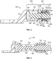
- Figure 3 is a cross-sectional view of a portion of the terminal assembly 100 showing the wire retention seal 110 and wire 102 loaded in the terminal 101, prior to crimping the terminal 101 around the wire 102.
- Figure 4 is a cross-sectional view of a portion of the terminal assembly 100 showing the terminal 101 crimped to the wire 102.
- the wire retention seal 110 includes a tapered lead-in 148 at the rear end 118 to guide the wire 102 into the wire retention seal 110.
- the wire barrel 140 may additionally or alternatively include a tapered lead-in. The tapered lead-ins align the wire 102 with the opening in the wire retention seal 110 to prevent damage to the wire 102, such as to prevent bending of the strands of the wire 102 during insertion.
- the wire barrel 140 includes a conductor barrel 150 and a jacket barrel 152 rearward of the conductor barrel 150.
- the conductor barrel 150 is configured to be crimped to the conductor 104 of the wire 102.
- the jacket barrel 152 is configured to be crimped to the jacket 106 of the wire 102.
- the wire retention seal 110 is received in the wire barrel 140 such that the wire retention sleeve 114 is axially aligned with the jacket barrel 152.
- the wire retention sleeve 114 is radially spaced apart from the jacket barrel 152 prior to the jacket barrel 152 being crimped.
- the wire retention sleeve 114 is able to expand when the wire 102 is loaded therein.
- the wire retention sleeve 114 is movable within the insert passage 146 to position the wire 102 in the wire barrel 140.
- the wire retention sleeve 114 is spaced apart from the wire barrel 140 to allow the wire barrel 140 to compress during crimping prior to engaging the wire retention sleeve 114.
- the wire retention sleeve 114 is configured to be crimped between the wire barrel 140 of the terminal 101 and the wire 102 when the wire barrel 140 is crimped around the wire 102.
- the wire retention sleeve 114 receives the wire 102 by a tight fit.
- the wire retention sleeve 114 conforms to the wire 102 as the wire 102 is loaded through the wire bore 122.
- the wire retention sleeve 114 is stretched and expanded outward by the wire 102 to change the shape of the wire retention sleeve 114 when coupled to the wire 102.
- the diameter of the wire retention sleeve 114 increases when the wire 102 is loaded therein.
- the inner sealing rings 130 seal against the wire 102 when the wire 102 is loaded therein.
- the inner sealing rings 130 seal against the jacket 106 by a sealing engagement.
- the material of the wire retention seal 110 may create friction at the interface between the inner sealing rings 130 and the jacket 106 to hold the axial position of the wire 102 in the wire retention seal 110.
- the wire retention seal 110 is axially retained on the end of the wire 102 prior to crimping the wire barrel 140 to the wire 102.
- the terminal mounting flange 112 is held in a mounting channel 154 to hold an axial position of the wire retention seal 110 relative to the terminal 101.
- the mounting channel 154 may extend circumferentially around the passage 146.
- the terminal 101 may include rims 156 on the front and/or rear sides of the mounting channel 154 to hold the terminal mounting flange 112 in the mounting channel 154.
- the rear end 118 of the wire retention seal 110 is positioned forward of the rear end of the terminal 101 such that the wire retention seal 110 remains inside the terminal 101 when crimped. For example, when the wire retention seal 110 is compressed, the wire retention seal 110 does not flatten out of the passage 146. In various embodiments, the wire retention seal 110 is not visible from the rear end of the terminal 101.
- the wire retention seal 110 may be flush with the rear end of the terminal 101 such that the wire retention seal 110 is visible prior to the crimping process to visually ensure that the wire retention seal 110 did not move during loading or transport and is properly positioned prior to starting the crimping process.
- the wire retention sleeve 114 extends forward of the terminal mounting flange 112.
- the wire retention sleeve 114 is loosely held in the wire barrel 140 by the terminal mounting flange 112 such that the wire retention sleeve 114 is able to float relative to the wire barrel 140.
- the wire retention sleeve 114 is axially aligned with the jacket barrel 152 when assembled and is radially spaced apart from the jacket barrel 152 prior to the jacket barrel 152 being crimped.
- a relief space 158 is defined concentrically outside of the wire retention sleeve 114 between the wire barrel 140 and the wire retention sleeve 114.
- the relief space 158 provides a space for the wire retention sleeve 114 to expand when the wire 102 is loaded through the wire bore 122.
- the relief space 158 is eliminated when the wire barrel 140 is crimped to the wire retention sleeve 114 and the wire 102.
- the wire barrel 140 is compressed to close the relief space 158.
- the jacket barrel 152 has an interior surface 160 facing the wire retention sleeve 114.
- the jacket barrel 152 has a jacket barrel diameter 162 at the interior surface 160 before the jacket barrel 152 is crimped. The jacket barrel diameter 162 is reduced when the jacket barrel 152 is crimped.
- the jacket barrel 152 is at least partially crimped prior to engaging the wire retention sleeve 114.
- the wire retention sleeve 114 is not compressed through the entire crimp, reducing the risk of the wire retention sleeve 114 being moved during the crimping process, being damaged during the crimping process or being unevenly crimped (for example, bunched or folded) during the crimping process.
- the outer sealing rings 132 engage the jacket barrel 152 when crimped to seal against the terminal 101.
- Figure 5 is a cross-sectional view of a portion of the terminal assembly 100 showing the wire retention seal 110 and wire 102 loaded in the terminal 101 prior to crimping the terminal 101 around the wire 102 in accordance with an exemplary embodiment.
- the wire retention seal 110 is shown flush with a rear end 164 of the terminal 101.
- the wire retention seal 110 is visible prior to crimping to ensure that the wire retention seal 110 is properly seated at the correct location.
- the wire retention seal 110 includes a locating gland 170 engaging the rim 156 to prevent pull-out of the wire retention seal 110 from the passage 146.
- FIG. 6 is a cross-sectional view of a portion of a terminal assembly 200 showing a wire retention seal 210 in accordance with an exemplary embodiment.
- the wire retention seal 210 holds the wire 102 in a terminal 201, prior to crimping the terminal 201 around the wire 102.
- the terminal 201 is similar to the terminal 101 illustrated above; however, the terminal 201 includes a seal cavity 202 that receives the wire retention seal 210.
- the seal cavity 202 is defined between a front rim 204 and a rear rim 206.
- the wire retention seal 210 may be axially movable in the seal cavity 202 between the front and rear rims 204, 206.
- the front and rear rims 204, 206 contain the wire retention seal 210 in the terminal 201.
- the terminal 201 includes a tapered lead-in 208 at the rear to guide the wire 102 into the terminal 201.
- the wire retention seal 210 is formed from a sealing material, such as rubber, silicone rubber, or the like.
- the wire retention seal 210 includes a terminal mounting flange 212 used to secure the wire retention seal 210 to the terminal 201 during assembly.
- the terminal mounting flange 212 may be loaded into the terminal 201 prior to loading the wire 102 into the terminal 201.
- the terminal mounting flange 212 holds the axial position of the wire retention seal 210 in the terminal 201 for loading the wire 102 into the wire retention seal 210 and the terminal 201 during assembly.
- the terminal mounting flange 212 may extend an entire length of the wire retention seal 210.
- the wire retention seal 210 may be sealed against the wire 102 and sealed against the terminal 201.
- the wire retention seal 210 may be sealed against the terminal 201 prior to the terminal 201 being crimped around the wire 102.
- the wire retention seal 210 is configured to be positioned between the wire 102 and the terminal 201 and is crimped against the wire 102 when the terminal 201 is crimped to the wire 102.
- the wire retention seal 210 is configured to be sealed to the insulating jacket 106.
- the wire retention seal 210 includes a wire retention sleeve 214 extending from the terminal mounting flange 212.
- the wire retention sleeve 214 receives an end of the wire 102 and is used to retain the wire 102 in the terminal 201 prior to crimping and/or to retain the terminal 201 on the wire 102 prior to crimping.
- the wire retention sleeve 214 is angled inward from the terminal mounting flange 212.
- the wire retention sleeve 214 may be spread open when the wire 102 is loaded therein to engage and hold the wire 102 therein, such as by an interference or friction fit.
- the wire retention seal 210 extends between a front end 216 and a rear end 218.
- the wire retention sleeve 214 may be provided at or near the front end 216.
- the front end 216 is configured to be loaded into the terminal 201.
- the wire 102 is rear loaded into the wire retention seal 210 through the rear end 218.
- the wire retention seal 210 is flush with the interior surface of a wire barrel 240 of the terminal 210.
- the wire seal 210 is compressed with the wire barrel 240 when the wire barrel 240 is crimped.
- the terminal mounting flange 212 is ring shaped and includes an opening 220 that receives the wire 102 during assembly.
- the wire retention sleeve 214 defines a wire bore 222 that receives the end of the wire 102 as the wire 102 is loaded through the opening 220.
- the wire bore 222 defines an internal passage through the wire retention seal 210.
- the wire retention seal 210 has an inner surface 224 configured to face the wire 102.
- the wire retention seal 210 has an outer surface 226 configured to face the terminal 201.
- the inner surface 224 has inner sealing rings 230 configured to seal against the wire 102.
- the outer surface 226 has outer sealing rings 232 configured to seal against the terminal 201.
- Embodiments of the present disclosure may provide simple and efficient systems and methods for securely connecting a wire to a terminal using the wire retention seal.
- the terminal may be held on the wire and transported to a crimping machine or manipulated within the crimping machine without changing the relative positions between the terminal and the wire leading to improved terminal crimps.
- a terminal assembly comprising: a terminal having a wire barrel configured to be crimped to a wire and a mating segment configured to be mated to a mating component; and a wire retention seal received in the wire barrel, the wire retention seal having a terminal mounting flange engaging the wire barrel to axially secure the wire retention seal to the terminal, the wire retention seal having a wire retention sleeve defining a wire bore configured to receive an end of the wire.
- the wire retention sleeve is configured to be crimped between the wire barrel of the terminal and the wire when the wire barrel is crimped around the wire.
- the wire retention sleeve is loosely held in the wire barrel by the terminal mounting flange such that the wire retention sleeve is able to float relative to the wire barrel.
- the wire retention sleeve includes inner ring seals sealable to the wire and outer ring seals sealable to the wire barrel.
- a relief space is defined concentrically between the wire barrel and the wire retention sleeve prior to crimping the wire barrel to the wire.
- the wire barrel includes a mounting channel receiving the terminal mounting flange to hold an axial position of the wire retention seal relative to the terminal.
- the wire barrel includes a conductor barrel and a jacket barrel rearward of the conductor barrel, the conductor barrel being configured to be crimped to a conductor of the wire, the jacket barrel being configured to be crimped to a jacket of the wire, the wire retention sleeve being axially aligned with the jacket barrel and being radially spaced apart from the jacket barrel prior to the jacket barrel being crimped.
- the jacket barrel has an interior surface having a first diameter before the wire barrel is crimped, the wire retention sleeve having a second diameter smaller than the first diameter.
- the terminal assembly may, further comprise the wire, the wire retention sleeve being configured to retain the terminal on the wire prior to the wire barrel being crimped to the wire.
- the wire retention sleeve extends forward of the terminal mounting flange.
- the wire retention sleeve includes a front end and a rear end, and the wire retention sleeve is provided at the front end.
- the rear end is exposed at a rear end of the terminal.
- the wire retention sleeve includes a tapered lead-in to the wire bore.
- a method of connecting the terminal assembly to a wire comprising firstly retaining the terminal on the wire with the wire retention sleeve prior to the wire barrel being crimped to the wire and secondly crimping the wire barrel to the wire.
Landscapes
- Engineering & Computer Science (AREA)
- Manufacturing & Machinery (AREA)
- Connections Effected By Soldering, Adhesion, Or Permanent Deformation (AREA)
Abstract
Description
- Embodiments of the present disclosure generally relate to wire retention seals for terminal assemblies.
- Terminal assemblies are used to provide power and/or data signals between various components. Some known terminal assemblies require environmental sealing between the wire and the terminal. Such terminal assemblies provide a seal in the terminal that is compressed with the wire barrel of the terminal during the crimping operation to corm the seal around the wire. The seal typically conforms to the terminal and has little or no interface with the wire prior to being crimped around the wire. A problem with such known terminal assemblies is that the terminal and seal tends to shift or move relative to the wire during handling and loading of the terminal into the crimping machine, leading to the possibility of the terminal and wire being improperly positioned during the crimping process and leading to a poor electrical connection and/or a poorly sealed connection.
- Other known terminal assemblies utilize an O-ring positioned in a seal cavity in the terminal that provides sealing between the wire and the terminal. However, the O-rings provide inconsistent seal performance and in some cases complete failure when the O-ring is displaced out of the seal cavity during wire insertion.
- Accordingly, the problem to be solved is a need for a simpler and more efficient wire seal for crimped terminal assemblies.
- The solution is provided by a terminal assembly including a terminal having a wire barrel configured to be crimped to a wire and a mating segment configured to be mated to a mating component. The terminal assembly includes a wire retention seal received in the wire barrel. The wire retention seal has a terminal mounting flange engaging the wire barrel to axially secure the wire retention seal to the terminal. The wire retention seal has a wire retention sleeve defining a wire bore configured to receive an end of the wire. The wire retention sleeve is configured to interfere with the wire to axially retain the wire retention seal on the end of the wire prior to crimping the wire barrel to the wire.
- The invention will now be described by way of example with reference to the accompanying drawings in which:
-
Figure 1 is an exploded view of a terminal assembly in accordance with an exemplary embodiment. -
Figure 2 is a perspective view of a terminal of the terminal assembly crimped to a wire and wire retention seal according to an embodiment. -
Figure 3 is a cross-sectional view of a portion of the terminal assembly showing the wire retention seal and wire loaded in the terminal prior to crimping the terminal around the wire. -
Figure 4 is a cross-sectional view of a portion of the terminal assembly showing the terminal crimped to the wire. -
Figure 5 is a cross-sectional view of a portion of the terminal assembly showing the wire retention seal and wire loaded in the terminal prior to crimping the terminal around the wire in accordance with an exemplary embodiment. -
Figure 6 is a cross-sectional view of a portion of a terminal assembly showing a wire retention seal in accordance with an exemplary embodiment. - In one embodiment, a terminal assembly is provided including a terminal having a wire barrel configured to be crimped to a wire and a mating segment configured to be mated to a mating component. The terminal assembly includes a wire retention seal received in the wire barrel. The wire retention seal has a terminal mounting flange engaging the wire barrel to axially secure the wire retention seal to the terminal. The wire retention seal has a wire retention sleeve defining a wire bore configured to receive an end of the wire. The wire retention sleeve is configured to interfere with the wire to axially retain the wire retention seal on the end of the wire prior to crimping the wire barrel to the wire.
- In another embodiment, a terminal assembly is provided including a terminal having a wire barrel configured to be crimped to a wire and a mating segment configured to be mated to a mating component. The terminal assembly includes a wire retention seal received in the wire barrel. The wire retention seal has a terminal mounting flange engaging the wire barrel to axially secure the wire retention seal to the terminal. The wire retention seal has a wire retention sleeve defining a wire bore configured to receive an end of the wire. The wire retention sleeve has an inner surface defining the wire bore and facing the wire and an outer surface facing the wire barrel. The inner surface has inner sealing rings configured to seal against the wire and the outer surface has outer sealing rings configured to seal against the wire barrel. The wire retention sleeve is configured to interfere with the wire to axially retain the wire retention seal on the end of the wire prior to crimping the wire barrel to the wire.
- In a further embodiment, a terminal assembly is provided including a terminal having a wire barrel configured to be crimped to a wire and a mating segment configured to be mated to a mating component. The wire barrel has a conductor barrel and a jacket barrel rearward of the conductor barrel. The conductor barrel is configured to be crimped to a conductor of the wire. The jacket barrel is configured to be crimped to a jacket of the wire. The terminal assembly includes a wire retention seal received in the jacket barrel. The wire retention seal has a terminal mounting flange engaging the wire barrel to axially secure the wire retention seal to the terminal. The wire retention seal has a wire retention sleeve defining a wire bore configured to receive an end of the wire. The wire retention seal is axially aligned with the jacket barrel and is radially spaced apart from the wire barrel prior to the wire barrel being crimped defining a relief space between the wire retention seal and the jacket barrel. The wire retention sleeve is configured to receive the end of the wire. The relief space provides a space for the wire retention sleeve to expand when the wire is loaded through the wire bore. The wire retention sleeve is configured to axially retain the wire retention seal on the end of the wire prior to crimping the wire barrel to the wire.
-
Figure 1 is an exploded view of aterminal assembly 100 in accordance with an exemplary embodiment. Theterminal assembly 100 includes aterminal 101, awire 102 configured to be terminated to theterminal 101, and awire retention seal 110 used to retain theterminal 101 on thewire 102 during assembly and to provide environmental sealing for thewire 102 and theterminal 101. Thewire 102 includes aninternal conductor 104 that is covered by an insulating cover orjacket 106. Theconductor 104 may be formed of a conductive metal, such as copper, aluminum, or the like. In an exemplary embodiment, theconductor 104 is a stranded wire. The insulatingjacket 106 is formed of an insulating material, such as rubber, plastic, or the like. Thewire 102 may include other layers such as a wire braid, an insulator layer, and the like. A portion of the insulatingjacket 106 is stripped in order to expose anend 108 of theconductor 104. In an exemplary embodiment, theterminal 101 is configured to be crimped to theend 108 of thewire 102 with thewire retention seal 110 positioned between thewire 102 and theterminal 101. - The
wire retention seal 110 is formed from a sealing material, such as rubber, silicone rubber, or the like. Thewire retention seal 110 includes aterminal mounting flange 112 used to secure thewire retention seal 110 to theterminal 101 during assembly. For example, theterminal mounting flange 112 may be loaded into theterminal 101 prior to loading thewire 102 into theterminal 101. Theterminal mounting flange 112 holds the axial position of thewire retention seal 110 in theterminal 101 for loading thewire 102 into thewire retention seal 110 and theterminal 101 during assembly. - The
wire retention seal 110 includes awire retention sleeve 114 extending from theterminal mounting flange 112. Thewire retention sleeve 114 receives theend 108 of thewire 102 and is used to retain thewire 102 in theterminal 101 prior to crimping and/or to retain theterminal 101 on thewire 102 prior to crimping. Thewire retention sleeve 114 may be sealed against thewire 102. Thewire retention sleeve 114 may be sealed against theterminal 101 when theterminal 101 is crimped around thewire 102. Thewire retention sleeve 114 is configured to be positioned between thewire 102 and theterminal 101 and is crimped against thewire 102 when theterminal 101 is crimped to thewire 102. Thewire retention sleeve 114 is configured to be sealed to the insulatingjacket 106. Optionally, thewire retention sleeve 114 is integral with theterminal mounting flange 112. For example, thewire retention sleeve 114 and theterminal mounting flange 112 may be co-molded or co-extruded from the same material. - The
wire retention seal 110 extends between afront end 116 and arear end 118. Thewire retention sleeve 114 is provided at or near thefront end 116. Theterminal mounting flanges 112 is provided at or near therear end 118. Thefront end 116 is configured to be loaded into the terminal 101. Thewire 102 is rear loaded into thewire retention seal 110 through therear end 118. Theterminal mounting flange 112 is ring shaped and includes anopening 120 that receives thewire 102 during assembly. Thewire retention sleeve 114 defines awire bore 122 that receives theend 108 of thewire 102 as thewire 102 is loaded through theopening 120. The wire bore 122 defines an internal passage through thewire retention seal 110. - The
wire retention sleeve 114 has aninner surface 124 defining the wire bore 122 and configured to face thewire 102. Thewire retention sleeve 114 has anouter surface 126 configured to face the terminal 101 when received therein. Theinner surface 124 has inner sealing rings 130 configured to seal against thewire 102. Theouter surface 126 has outer sealing rings 132 configured to seal against the terminal 101. The inner sealing rings 130 narrow aninner diameter 134 of the wire bore 122 to seal against thewire 102. The outer sealing rings 132 increase anouter diameter 136 of thewire retention sleeve 114 to seal against the terminal 101. Thewire retention sleeve 114 may be provided without any inner sealing rings 130 and/or without any outer sealing rings 132. - The insulating
jacket 106 of thewire 102 is stripped to expose theend 108 of theconductor 104 such that theexposed end 108 is sized and shaped to be inserted into the wire bore 122 of thewire retention sleeve 114. During assembly, after thewire retention seal 110 is positioned in the terminal 101, thewire 102 is axially aligned with thewire retention seal 110 and urged into the wire bore 122 until theexposed end 108 of theconductor 104 is loaded through thewire retention seal 110 into the terminal 101. Thewire retention seal 110 is flexible allowing thewire 102 to be inserted without damaging thewire 102. For example, thewire retention seal 110 does not damage or bend the individual wire strands as thewire 102 is loaded through thewire retention seal 110. When loaded, the end of the insulatingjacket 106 is received in the wire bore 122. Thewire 102 is configured to be held in the wire bore 122 of thewire retention sleeve 114 by an interference fit to axially secure the terminal 101 and thewire retention seal 110 on thewire 102. When thewire retention sleeve 114 engages thewire 102, thewire retention sleeve 114 does not slide along thewire 102, but rather holds tight to thewire 102 to avoid having the terminal fall off the end of thewire 102. As such, thewire 102 and the terminal 101 may be manipulated together as a unit. For example, thewire 102 and the terminal 101 may be transported to a crimping machine or other processing machine without needing to separately hold thewire 102 and the terminal 101. There is less risk of the terminal 101 and thewire 102 shifting relative to each other during the crimping process. Alternatively, instead of positioning thewire retention seal 110 in the terminal 101, thewire retention seal 110 may first be positioned on thewire 102 and then loaded into the terminal 101. - The terminal 101 may be any type of terminal. In an exemplary embodiment, the terminal 101 is a crimp terminal configured to be crimped to the
wire 102. The terminal 101 includes awire barrel 140 connected to a base 142 at amating segment 144 of the terminal. The base 142 may be a flat strap, panel, tab, pin, socket, or the like, which is configured to be electrically and mechanically connected to a component, device, or the like. For example, thebase 142 may be a bolting tongue configured to be bolted to another component. Thewire barrel 140 includes a chamber that defines aninsert passage 146. Thewire retention seal 110 is inserted into theinsert passage 146. For example, theterminal mounting flange 112 is loaded into theinsert passage 146 and secured therein to axially secure thewire retention seal 110 to the terminal 101. Optionally, the entirewire retention seal 110 is loaded into theinsert passage 146. Optionally, therear end 118 may be visible at the rear end of the terminal 101 to ensure proper positioning of thewire retention seal 110 in theterminal 101. - Once the
wire retention seal 110 and thewire 102 are loaded into thewire barrel 140, a crimping tool is used to crimp thewire barrel 140 to the assembly. During the crimping operation, thewire barrel 140 is crimped around thewire retention seal 110 such that internal walls that define the crimping chamber compress into thewire retention seal 110, which therefore compresses into thejacket 106 of thewire 102 to create a seal between the terminal 101 and thejacket 106 of thewire 102. A fluid-tight seal is created by thewire retention seal 110 between thejacket 106 and thewire barrel 140. The terminal 101 is also compressed into theconductor 104 of thewire 102 to create an electrical connection between the terminal 101 and thewire 102. Accordingly, a single crimping operation may electrically and mechanically connect the terminal 101 to thewire 102 and, at the same time, provide a fluid-tight seal between the terminal 101 and thewire retention seal 110, as well as a fluid-tight seal between thewire retention seal 110 and the insulatingjacket 106. -
Figure 2 is a perspective view of the terminal 101 crimped to thewire 102 and thewire retention seal 110 according to an embodiment of the present disclosure. A crimping tool is operated to form a crimp at an area that compressively crimps thewire barrel 140 to thewire 102, which, in turn, crimps thewire retention seal 110 between thewire 102 and the terminal 101. -
Figure 3 is a cross-sectional view of a portion of theterminal assembly 100 showing thewire retention seal 110 andwire 102 loaded in the terminal 101, prior to crimping the terminal 101 around thewire 102.Figure 4 is a cross-sectional view of a portion of theterminal assembly 100 showing the terminal 101 crimped to thewire 102. Thewire retention seal 110 includes a tapered lead-in 148 at therear end 118 to guide thewire 102 into thewire retention seal 110. Optionally, thewire barrel 140 may additionally or alternatively include a tapered lead-in. The tapered lead-ins align thewire 102 with the opening in thewire retention seal 110 to prevent damage to thewire 102, such as to prevent bending of the strands of thewire 102 during insertion. In an exemplary embodiment, thewire barrel 140 includes aconductor barrel 150 and ajacket barrel 152 rearward of theconductor barrel 150. Theconductor barrel 150 is configured to be crimped to theconductor 104 of thewire 102. Thejacket barrel 152 is configured to be crimped to thejacket 106 of thewire 102. Thewire retention seal 110 is received in thewire barrel 140 such that thewire retention sleeve 114 is axially aligned with thejacket barrel 152. - In an exemplary embodiment, the
wire retention sleeve 114 is radially spaced apart from thejacket barrel 152 prior to thejacket barrel 152 being crimped. Thewire retention sleeve 114 is able to expand when thewire 102 is loaded therein. Thewire retention sleeve 114 is movable within theinsert passage 146 to position thewire 102 in thewire barrel 140. Thewire retention sleeve 114 is spaced apart from thewire barrel 140 to allow thewire barrel 140 to compress during crimping prior to engaging thewire retention sleeve 114. Thewire retention sleeve 114 is configured to be crimped between thewire barrel 140 of the terminal 101 and thewire 102 when thewire barrel 140 is crimped around thewire 102. - The
wire retention sleeve 114 receives thewire 102 by a tight fit. For example, thewire retention sleeve 114 conforms to thewire 102 as thewire 102 is loaded through the wire bore 122. Thewire retention sleeve 114 is stretched and expanded outward by thewire 102 to change the shape of thewire retention sleeve 114 when coupled to thewire 102. For example, the diameter of thewire retention sleeve 114 increases when thewire 102 is loaded therein. The inner sealing rings 130 seal against thewire 102 when thewire 102 is loaded therein. For example, the inner sealing rings 130 seal against thejacket 106 by a sealing engagement. The material of thewire retention seal 110 may create friction at the interface between the inner sealing rings 130 and thejacket 106 to hold the axial position of thewire 102 in thewire retention seal 110. Thewire retention seal 110 is axially retained on the end of thewire 102 prior to crimping thewire barrel 140 to thewire 102. - The
terminal mounting flange 112 is held in a mountingchannel 154 to hold an axial position of thewire retention seal 110 relative to the terminal 101. The mountingchannel 154 may extend circumferentially around thepassage 146. The terminal 101 may includerims 156 on the front and/or rear sides of the mountingchannel 154 to hold theterminal mounting flange 112 in the mountingchannel 154. Optionally, therear end 118 of thewire retention seal 110 is positioned forward of the rear end of the terminal 101 such that thewire retention seal 110 remains inside the terminal 101 when crimped. For example, when thewire retention seal 110 is compressed, thewire retention seal 110 does not flatten out of thepassage 146. In various embodiments, thewire retention seal 110 is not visible from the rear end of the terminal 101. In other various embodiments, thewire retention seal 110 may be flush with the rear end of the terminal 101 such that thewire retention seal 110 is visible prior to the crimping process to visually ensure that thewire retention seal 110 did not move during loading or transport and is properly positioned prior to starting the crimping process. - The
wire retention sleeve 114 extends forward of theterminal mounting flange 112. Thewire retention sleeve 114 is loosely held in thewire barrel 140 by theterminal mounting flange 112 such that thewire retention sleeve 114 is able to float relative to thewire barrel 140. Thewire retention sleeve 114 is axially aligned with thejacket barrel 152 when assembled and is radially spaced apart from thejacket barrel 152 prior to thejacket barrel 152 being crimped. For example, a relief space 158 is defined concentrically outside of thewire retention sleeve 114 between thewire barrel 140 and thewire retention sleeve 114. The relief space 158 provides a space for thewire retention sleeve 114 to expand when thewire 102 is loaded through the wire bore 122. The relief space 158 is eliminated when thewire barrel 140 is crimped to thewire retention sleeve 114 and thewire 102. For example, thewire barrel 140 is compressed to close the relief space 158. Thejacket barrel 152 has aninterior surface 160 facing thewire retention sleeve 114. Thejacket barrel 152 has ajacket barrel diameter 162 at theinterior surface 160 before thejacket barrel 152 is crimped. Thejacket barrel diameter 162 is reduced when thejacket barrel 152 is crimped. However, because theouter diameter 136 of thewire retention sleeve 114 is smaller than thejacket barrel diameter 162, thejacket barrel 152 is at least partially crimped prior to engaging thewire retention sleeve 114. As such, thewire retention sleeve 114 is not compressed through the entire crimp, reducing the risk of thewire retention sleeve 114 being moved during the crimping process, being damaged during the crimping process or being unevenly crimped (for example, bunched or folded) during the crimping process. The outer sealing rings 132 engage thejacket barrel 152 when crimped to seal against the terminal 101. -
Figure 5 is a cross-sectional view of a portion of theterminal assembly 100 showing thewire retention seal 110 andwire 102 loaded in the terminal 101 prior to crimping the terminal 101 around thewire 102 in accordance with an exemplary embodiment. Thewire retention seal 110 is shown flush with arear end 164 of the terminal 101. Thewire retention seal 110 is visible prior to crimping to ensure that thewire retention seal 110 is properly seated at the correct location. Thewire retention seal 110 includes a locatinggland 170 engaging therim 156 to prevent pull-out of thewire retention seal 110 from thepassage 146. -
Figure 6 is a cross-sectional view of a portion of aterminal assembly 200 showing awire retention seal 210 in accordance with an exemplary embodiment. Thewire retention seal 210 holds thewire 102 in a terminal 201, prior to crimping the terminal 201 around thewire 102. The terminal 201 is similar to the terminal 101 illustrated above; however, the terminal 201 includes aseal cavity 202 that receives thewire retention seal 210. Theseal cavity 202 is defined between afront rim 204 and a rear rim 206. Optionally, thewire retention seal 210 may be axially movable in theseal cavity 202 between the front andrear rims 204, 206. The front andrear rims 204, 206 contain thewire retention seal 210 in theterminal 201. The terminal 201 includes a tapered lead-in 208 at the rear to guide thewire 102 into the terminal 201. - The
wire retention seal 210 is formed from a sealing material, such as rubber, silicone rubber, or the like. Thewire retention seal 210 includes aterminal mounting flange 212 used to secure thewire retention seal 210 to the terminal 201 during assembly. For example, theterminal mounting flange 212 may be loaded into the terminal 201 prior to loading thewire 102 into the terminal 201. Theterminal mounting flange 212 holds the axial position of thewire retention seal 210 in the terminal 201 for loading thewire 102 into thewire retention seal 210 and the terminal 201 during assembly. Theterminal mounting flange 212 may extend an entire length of thewire retention seal 210. - The
wire retention seal 210 may be sealed against thewire 102 and sealed against the terminal 201. Thewire retention seal 210 may be sealed against the terminal 201 prior to the terminal 201 being crimped around thewire 102. Thewire retention seal 210 is configured to be positioned between thewire 102 and the terminal 201 and is crimped against thewire 102 when the terminal 201 is crimped to thewire 102. Thewire retention seal 210 is configured to be sealed to the insulatingjacket 106. - The
wire retention seal 210 includes awire retention sleeve 214 extending from theterminal mounting flange 212. Thewire retention sleeve 214 receives an end of thewire 102 and is used to retain thewire 102 in the terminal 201 prior to crimping and/or to retain the terminal 201 on thewire 102 prior to crimping. In an exemplary embodiment, thewire retention sleeve 214 is angled inward from theterminal mounting flange 212. Thewire retention sleeve 214 may be spread open when thewire 102 is loaded therein to engage and hold thewire 102 therein, such as by an interference or friction fit. - The
wire retention seal 210 extends between afront end 216 and arear end 218. Thewire retention sleeve 214 may be provided at or near thefront end 216. Thefront end 216 is configured to be loaded into the terminal 201. Thewire 102 is rear loaded into thewire retention seal 210 through therear end 218. In an exemplary embodiment, thewire retention seal 210 is flush with the interior surface of awire barrel 240 of the terminal 210. Thewire seal 210 is compressed with thewire barrel 240 when thewire barrel 240 is crimped. Theterminal mounting flange 212 is ring shaped and includes anopening 220 that receives thewire 102 during assembly. Thewire retention sleeve 214 defines awire bore 222 that receives the end of thewire 102 as thewire 102 is loaded through theopening 220. The wire bore 222 defines an internal passage through thewire retention seal 210. - The
wire retention seal 210 has aninner surface 224 configured to face thewire 102. Thewire retention seal 210 has anouter surface 226 configured to face theterminal 201. Theinner surface 224 has inner sealing rings 230 configured to seal against thewire 102. Theouter surface 226 has outer sealing rings 232 configured to seal against the terminal 201. - Embodiments of the present disclosure may provide simple and efficient systems and methods for securely connecting a wire to a terminal using the wire retention seal. The terminal may be held on the wire and transported to a crimping machine or manipulated within the crimping machine without changing the relative positions between the terminal and the wire leading to improved terminal crimps.
- According to the invention there is provided a terminal assembly comprising: a terminal having a wire barrel configured to be crimped to a wire and a mating segment configured to be mated to a mating component; and a wire retention seal received in the wire barrel, the wire retention seal having a terminal mounting flange engaging the wire barrel to axially secure the wire retention seal to the terminal, the wire retention seal having a wire retention sleeve defining a wire bore configured to receive an end of the wire. Preferably the wire retention sleeve is configured to be crimped between the wire barrel of the terminal and the wire when the wire barrel is crimped around the wire. Preferably the wire retention sleeve is loosely held in the wire barrel by the terminal mounting flange such that the wire retention sleeve is able to float relative to the wire barrel. Preferably the wire retention sleeve includes inner ring seals sealable to the wire and outer ring seals sealable to the wire barrel. Preferably a relief space is defined concentrically between the wire barrel and the wire retention sleeve prior to crimping the wire barrel to the wire. Preferably the wire barrel includes a mounting channel receiving the terminal mounting flange to hold an axial position of the wire retention seal relative to the terminal. Preferably the wire barrel includes a conductor barrel and a jacket barrel rearward of the conductor barrel, the conductor barrel being configured to be crimped to a conductor of the wire, the jacket barrel being configured to be crimped to a jacket of the wire, the wire retention sleeve being axially aligned with the jacket barrel and being radially spaced apart from the jacket barrel prior to the jacket barrel being crimped. Preferably the jacket barrel has an interior surface having a first diameter before the wire barrel is crimped, the wire retention sleeve having a second diameter smaller than the first diameter. The terminal assembly may, further comprise the wire, the wire retention sleeve being configured to retain the terminal on the wire prior to the wire barrel being crimped to the wire. Preferably the wire retention sleeve extends forward of the terminal mounting flange. Preferably the wire retention sleeve includes a front end and a rear end, and the wire retention sleeve is provided at the front end. Preferably the rear end is exposed at a rear end of the terminal. Preferably the wire retention sleeve includes a tapered lead-in to the wire bore.
- According to a further aspect of the invention there is provided a method of connecting the terminal assembly to a wire comprising firstly retaining the terminal on the wire with the wire retention sleeve prior to the wire barrel being crimped to the wire and secondly crimping the wire barrel to the wire.
Claims (14)
- A terminal assembly (100) comprising:a terminal (101) having a wire barrel (140) configured to be crimped to a wire (102) and a mating segment (144) configured to be mated to a mating component; anda wire retention seal (110) received in the wire barrel (140), the wire retention seal (110) having a terminal mounting flange (112) engaging the wire barrel (140) to axially secure the wire retention seal (110) to the terminal (101), the wire retention seal (110) having a wire retention sleeve (114) defining a wire bore (122) configured to receive an end (108) of the wire (102), the wire retention sleeve (114) being configured to interfere with the wire (102) to axially retain the wire retention seal (110) on the end (108) of the wire (102) prior to crimping the wire barrel (140) to the wire (102).
- The terminal assembly (100) of claim 1, wherein the wire retention sleeve (114) is configured to be crimped between the wire barrel (140) of the terminal (101) and the wire (102) when the wire barrel (140) is crimped around the wire (102).
- The terminal assembly (100) of claim 1 or 2, wherein the wire retention sleeve (114) is loosely held in the wire barrel (140) by the terminal mounting flange (112) such that the wire retention sleeve (114) is able to float relative to the wire barrel (140).
- The terminal assembly (100) of any preceding claim, wherein the wire retention sleeve (114) includes inner ring seals (130) sealable to the wire (102) and outer ring seals (132) sealable to the wire barrel (140).
- The terminal assembly of any preceding claim, wherein a relief space (158) is defined concentrically between the wire barrel (140) and the wire retention sleeve (114), the relief space (158) configured to be eliminated when the wire barrel (140) is crimped to the wire retention sleeve (114) and the wire (102).
- The terminal assembly (100) of any preceding claim, wherein the wire barrel (140) includes a mounting channel (154) receiving the terminal mounting flange (112) to hold an axial position of the wire retention seal (110) relative to the terminal (101).
- The terminal assembly (100) of any preceding claim, wherein the wire barrel (140) includes a conductor barrel (150) and a jacket barrel (152) rearward of the conductor barrel (150), the conductor barrel (150) being configured to be crimped to a conductor (104) of the wire (102), the jacket barrel (152) being configured to be crimped to a jacket (106) of the wire (102), the wire retention sleeve (114) being axially aligned with the jacket barrel (152) and being radially spaced apart from the jacket barrel (152) prior to the jacket barrel (152) being crimped.
- The terminal assembly (100) of claim 7, wherein the jacket barrel (152) has an interior surface (160) having a first diameter (162) before the wire barrel (140) is crimped, the wire retention sleeve (114) having a second diameter (136) smaller than the first diameter (162).
- The terminal assembly (100) of any preceding claim, further comprising the wire (102), the wire retention sleeve (114) retaining the terminal (101) on the wire (102) prior to the wire barrel (140) being crimped to the wire (102).
- The terminal assembly (100) of any preceding claim, wherein the wire retention sleeve (114) extends forward of the terminal mounting flange (112).
- The terminal assembly (100) of any preceding claim, wherein the wire retention sleeve (114) includes a front end (116) and a rear end (118), the wire retention sleeve (114) provided at the front end.
- The terminal assembly (100) of claim 11, wherein the rear end (118) is exposed at a rear end of the terminal (101).
- The terminal assembly (100) of any preceding claim, wherein the wire retention sleeve (114) includes a tapered lead-in (208) to the wire bore (122).
- A method of connecting a terminal assembly (100) according to any preceding claim to a wire (102) comprising firstly retaining the terminal (101) on the wire (102) with the wire retention sleeve (114) prior to the wire barrel (140) being crimped to the wire (102) and secondly crimping the wire barrel (140) to the wire (102).
Applications Claiming Priority (1)
| Application Number | Priority Date | Filing Date | Title |
|---|---|---|---|
| US15/434,626 US9859626B1 (en) | 2017-02-16 | 2017-02-16 | Wire retention seal for a terminal assembly |
Publications (2)
| Publication Number | Publication Date |
|---|---|
| EP3364503A1 true EP3364503A1 (en) | 2018-08-22 |
| EP3364503B1 EP3364503B1 (en) | 2020-09-30 |
Family
ID=60788956
Family Applications (1)
| Application Number | Title | Priority Date | Filing Date |
|---|---|---|---|
| EP18156981.5A Active EP3364503B1 (en) | 2017-02-16 | 2018-02-15 | Terminal assembly with a wire retention seal and method of connecting thereof |
Country Status (2)
| Country | Link |
|---|---|
| US (1) | US9859626B1 (en) |
| EP (1) | EP3364503B1 (en) |
Cited By (1)
| Publication number | Priority date | Publication date | Assignee | Title |
|---|---|---|---|---|
| EP4654387A1 (en) * | 2024-05-21 | 2025-11-26 | Yazaki Corporation | Terminal waterproof structure |
Families Citing this family (1)
| Publication number | Priority date | Publication date | Assignee | Title |
|---|---|---|---|---|
| CN109861052A (en) * | 2019-04-12 | 2019-06-07 | 苏州弘毅辉自动化设备有限公司 | A kind of air-blowing with detection function, riveting all-in-one machine |
Citations (3)
| Publication number | Priority date | Publication date | Assignee | Title |
|---|---|---|---|---|
| GB2371418A (en) * | 2001-01-19 | 2002-07-24 | Yazaki Corp | Waterproof connection |
| US20060014412A1 (en) * | 2004-07-13 | 2006-01-19 | Yazaki Europe Ltd. | Connection between a cable end piece and a cable end |
| FR2920599A1 (en) * | 2007-09-05 | 2009-03-06 | Mecatraction Sa | Lug for electric connection, has socket presenting hollow partially filled with contact grease that is placed between base of hollow and transversal membrane, and stopper maintaining grease and hollow |
Family Cites Families (3)
| Publication number | Priority date | Publication date | Assignee | Title |
|---|---|---|---|---|
| JP2004265668A (en) * | 2003-02-28 | 2004-09-24 | Sumitomo Wiring Syst Ltd | Terminal fittings |
| US9385449B2 (en) * | 2009-02-16 | 2016-07-05 | Carlisle Interconnect Technologies, Inc. | Terminal/connector having integral oxide breaker element |
| WO2011031676A2 (en) * | 2009-09-10 | 2011-03-17 | Mayo Foundation For Medical Education And Research | Depleting immunosuppressive monocytes within a mammal |
-
2017
- 2017-02-16 US US15/434,626 patent/US9859626B1/en active Active
-
2018
- 2018-02-15 EP EP18156981.5A patent/EP3364503B1/en active Active
Patent Citations (3)
| Publication number | Priority date | Publication date | Assignee | Title |
|---|---|---|---|---|
| GB2371418A (en) * | 2001-01-19 | 2002-07-24 | Yazaki Corp | Waterproof connection |
| US20060014412A1 (en) * | 2004-07-13 | 2006-01-19 | Yazaki Europe Ltd. | Connection between a cable end piece and a cable end |
| FR2920599A1 (en) * | 2007-09-05 | 2009-03-06 | Mecatraction Sa | Lug for electric connection, has socket presenting hollow partially filled with contact grease that is placed between base of hollow and transversal membrane, and stopper maintaining grease and hollow |
Cited By (1)
| Publication number | Priority date | Publication date | Assignee | Title |
|---|---|---|---|---|
| EP4654387A1 (en) * | 2024-05-21 | 2025-11-26 | Yazaki Corporation | Terminal waterproof structure |
Also Published As
| Publication number | Publication date |
|---|---|
| US9859626B1 (en) | 2018-01-02 |
| EP3364503B1 (en) | 2020-09-30 |
Similar Documents
| Publication | Publication Date | Title |
|---|---|---|
| US9106066B2 (en) | Wire fixing member | |
| US3787796A (en) | Low cost sealed connector and method of making same | |
| EP2909891B1 (en) | Coaxial cable connector with a compressible ferrule | |
| US3170752A (en) | Electrical connector apparatus | |
| US8231408B2 (en) | Connector | |
| US10622755B1 (en) | Connector assembly and method of assembling same | |
| US3828305A (en) | Terminal connector and method of attaching same to coaxial cable | |
| EP3139446B1 (en) | Coaxial cable connector | |
| US3297979A (en) | Crimpable coaxial connector | |
| CA2978208A1 (en) | Method for producing a plug connector arrangement | |
| US9548556B2 (en) | Connector | |
| CN104205521A (en) | Structure for connecting braided shield wiring and method for manufacturing shield-wire harness | |
| US7101223B2 (en) | Compact sealed and shielded connector | |
| US7064266B2 (en) | Shielded connector | |
| EP2390963B1 (en) | Connector, connector assembly and connector production method | |
| EP4270665A1 (en) | High speed cable braid termination using a coil spring | |
| EP2390964A1 (en) | Connector and connector assembly | |
| US20160036138A1 (en) | Coaxial cable connectors with conductor retaining members | |
| EP3364503B1 (en) | Terminal assembly with a wire retention seal and method of connecting thereof | |
| US20250030213A1 (en) | High Deformation and Retention Ferrule | |
| CN113196590A (en) | Connector structure and method for manufacturing connector structure | |
| CN110932009A (en) | Insulation crimp with lead-in | |
| US4192566A (en) | Antenna lead splice | |
| JP5016411B2 (en) | Waterproof connector | |
| GB2272804A (en) | A seal for a waterproof connector |
Legal Events
| Date | Code | Title | Description |
|---|---|---|---|
| PUAI | Public reference made under article 153(3) epc to a published international application that has entered the european phase |
Free format text: ORIGINAL CODE: 0009012 |
|
| STAA | Information on the status of an ep patent application or granted ep patent |
Free format text: STATUS: THE APPLICATION HAS BEEN PUBLISHED |
|
| AK | Designated contracting states |
Kind code of ref document: A1 Designated state(s): AL AT BE BG CH CY CZ DE DK EE ES FI FR GB GR HR HU IE IS IT LI LT LU LV MC MK MT NL NO PL PT RO RS SE SI SK SM TR |
|
| AX | Request for extension of the european patent |
Extension state: BA ME |
|
| STAA | Information on the status of an ep patent application or granted ep patent |
Free format text: STATUS: REQUEST FOR EXAMINATION WAS MADE |
|
| 17P | Request for examination filed |
Effective date: 20190212 |
|
| RBV | Designated contracting states (corrected) |
Designated state(s): AL AT BE BG CH CY CZ DE DK EE ES FI FR GB GR HR HU IE IS IT LI LT LU LV MC MK MT NL NO PL PT RO RS SE SI SK SM TR |
|
| STAA | Information on the status of an ep patent application or granted ep patent |
Free format text: STATUS: EXAMINATION IS IN PROGRESS |
|
| 17Q | First examination report despatched |
Effective date: 20190409 |
|
| RIC1 | Information provided on ipc code assigned before grant |
Ipc: H01R 43/048 20060101ALI20200325BHEP Ipc: H01R 43/00 20060101ALI20200325BHEP Ipc: H01R 13/52 20060101AFI20200325BHEP Ipc: H01R 4/20 20060101ALI20200325BHEP Ipc: H01R 11/12 20060101ALN20200325BHEP |
|
| GRAP | Despatch of communication of intention to grant a patent |
Free format text: ORIGINAL CODE: EPIDOSNIGR1 |
|
| STAA | Information on the status of an ep patent application or granted ep patent |
Free format text: STATUS: GRANT OF PATENT IS INTENDED |
|
| INTG | Intention to grant announced |
Effective date: 20200508 |
|
| GRAS | Grant fee paid |
Free format text: ORIGINAL CODE: EPIDOSNIGR3 |
|
| GRAA | (expected) grant |
Free format text: ORIGINAL CODE: 0009210 |
|
| STAA | Information on the status of an ep patent application or granted ep patent |
Free format text: STATUS: THE PATENT HAS BEEN GRANTED |
|
| AK | Designated contracting states |
Kind code of ref document: B1 Designated state(s): AL AT BE BG CH CY CZ DE DK EE ES FI FR GB GR HR HU IE IS IT LI LT LU LV MC MK MT NL NO PL PT RO RS SE SI SK SM TR |
|
| REG | Reference to a national code |
Ref country code: GB Ref legal event code: FG4D Ref country code: CH Ref legal event code: EP |
|
| REG | Reference to a national code |
Ref country code: AT Ref legal event code: REF Ref document number: 1319756 Country of ref document: AT Kind code of ref document: T Effective date: 20201015 |
|
| REG | Reference to a national code |
Ref country code: DE Ref legal event code: R096 Ref document number: 602018008163 Country of ref document: DE |
|
| REG | Reference to a national code |
Ref country code: IE Ref legal event code: FG4D |
|
| PG25 | Lapsed in a contracting state [announced via postgrant information from national office to epo] |
Ref country code: GR Free format text: LAPSE BECAUSE OF FAILURE TO SUBMIT A TRANSLATION OF THE DESCRIPTION OR TO PAY THE FEE WITHIN THE PRESCRIBED TIME-LIMIT Effective date: 20201231 Ref country code: FI Free format text: LAPSE BECAUSE OF FAILURE TO SUBMIT A TRANSLATION OF THE DESCRIPTION OR TO PAY THE FEE WITHIN THE PRESCRIBED TIME-LIMIT Effective date: 20200930 Ref country code: NO Free format text: LAPSE BECAUSE OF FAILURE TO SUBMIT A TRANSLATION OF THE DESCRIPTION OR TO PAY THE FEE WITHIN THE PRESCRIBED TIME-LIMIT Effective date: 20201230 Ref country code: HR Free format text: LAPSE BECAUSE OF FAILURE TO SUBMIT A TRANSLATION OF THE DESCRIPTION OR TO PAY THE FEE WITHIN THE PRESCRIBED TIME-LIMIT Effective date: 20200930 Ref country code: SE Free format text: LAPSE BECAUSE OF FAILURE TO SUBMIT A TRANSLATION OF THE DESCRIPTION OR TO PAY THE FEE WITHIN THE PRESCRIBED TIME-LIMIT Effective date: 20200930 Ref country code: BG Free format text: LAPSE BECAUSE OF FAILURE TO SUBMIT A TRANSLATION OF THE DESCRIPTION OR TO PAY THE FEE WITHIN THE PRESCRIBED TIME-LIMIT Effective date: 20201230 |
|
| REG | Reference to a national code |
Ref country code: AT Ref legal event code: MK05 Ref document number: 1319756 Country of ref document: AT Kind code of ref document: T Effective date: 20200930 |
|
| PG25 | Lapsed in a contracting state [announced via postgrant information from national office to epo] |
Ref country code: LV Free format text: LAPSE BECAUSE OF FAILURE TO SUBMIT A TRANSLATION OF THE DESCRIPTION OR TO PAY THE FEE WITHIN THE PRESCRIBED TIME-LIMIT Effective date: 20200930 Ref country code: RS Free format text: LAPSE BECAUSE OF FAILURE TO SUBMIT A TRANSLATION OF THE DESCRIPTION OR TO PAY THE FEE WITHIN THE PRESCRIBED TIME-LIMIT Effective date: 20200930 |
|
| REG | Reference to a national code |
Ref country code: NL Ref legal event code: MP Effective date: 20200930 |
|
| REG | Reference to a national code |
Ref country code: LT Ref legal event code: MG4D |
|
| PG25 | Lapsed in a contracting state [announced via postgrant information from national office to epo] |
Ref country code: LT Free format text: LAPSE BECAUSE OF FAILURE TO SUBMIT A TRANSLATION OF THE DESCRIPTION OR TO PAY THE FEE WITHIN THE PRESCRIBED TIME-LIMIT Effective date: 20200930 Ref country code: SM Free format text: LAPSE BECAUSE OF FAILURE TO SUBMIT A TRANSLATION OF THE DESCRIPTION OR TO PAY THE FEE WITHIN THE PRESCRIBED TIME-LIMIT Effective date: 20200930 Ref country code: EE Free format text: LAPSE BECAUSE OF FAILURE TO SUBMIT A TRANSLATION OF THE DESCRIPTION OR TO PAY THE FEE WITHIN THE PRESCRIBED TIME-LIMIT Effective date: 20200930 Ref country code: PT Free format text: LAPSE BECAUSE OF FAILURE TO SUBMIT A TRANSLATION OF THE DESCRIPTION OR TO PAY THE FEE WITHIN THE PRESCRIBED TIME-LIMIT Effective date: 20210201 Ref country code: RO Free format text: LAPSE BECAUSE OF FAILURE TO SUBMIT A TRANSLATION OF THE DESCRIPTION OR TO PAY THE FEE WITHIN THE PRESCRIBED TIME-LIMIT Effective date: 20200930 Ref country code: CZ Free format text: LAPSE BECAUSE OF FAILURE TO SUBMIT A TRANSLATION OF THE DESCRIPTION OR TO PAY THE FEE WITHIN THE PRESCRIBED TIME-LIMIT Effective date: 20200930 |
|
| PG25 | Lapsed in a contracting state [announced via postgrant information from national office to epo] |
Ref country code: IS Free format text: LAPSE BECAUSE OF FAILURE TO SUBMIT A TRANSLATION OF THE DESCRIPTION OR TO PAY THE FEE WITHIN THE PRESCRIBED TIME-LIMIT Effective date: 20210130 Ref country code: PL Free format text: LAPSE BECAUSE OF FAILURE TO SUBMIT A TRANSLATION OF THE DESCRIPTION OR TO PAY THE FEE WITHIN THE PRESCRIBED TIME-LIMIT Effective date: 20200930 Ref country code: AL Free format text: LAPSE BECAUSE OF FAILURE TO SUBMIT A TRANSLATION OF THE DESCRIPTION OR TO PAY THE FEE WITHIN THE PRESCRIBED TIME-LIMIT Effective date: 20200930 Ref country code: AT Free format text: LAPSE BECAUSE OF FAILURE TO SUBMIT A TRANSLATION OF THE DESCRIPTION OR TO PAY THE FEE WITHIN THE PRESCRIBED TIME-LIMIT Effective date: 20200930 Ref country code: ES Free format text: LAPSE BECAUSE OF FAILURE TO SUBMIT A TRANSLATION OF THE DESCRIPTION OR TO PAY THE FEE WITHIN THE PRESCRIBED TIME-LIMIT Effective date: 20200930 |
|
| PG25 | Lapsed in a contracting state [announced via postgrant information from national office to epo] |
Ref country code: NL Free format text: LAPSE BECAUSE OF FAILURE TO SUBMIT A TRANSLATION OF THE DESCRIPTION OR TO PAY THE FEE WITHIN THE PRESCRIBED TIME-LIMIT Effective date: 20200930 Ref country code: SK Free format text: LAPSE BECAUSE OF FAILURE TO SUBMIT A TRANSLATION OF THE DESCRIPTION OR TO PAY THE FEE WITHIN THE PRESCRIBED TIME-LIMIT Effective date: 20200930 |
|
| REG | Reference to a national code |
Ref country code: DE Ref legal event code: R097 Ref document number: 602018008163 Country of ref document: DE |
|
| PLBE | No opposition filed within time limit |
Free format text: ORIGINAL CODE: 0009261 |
|
| STAA | Information on the status of an ep patent application or granted ep patent |
Free format text: STATUS: NO OPPOSITION FILED WITHIN TIME LIMIT |
|
| PG25 | Lapsed in a contracting state [announced via postgrant information from national office to epo] |
Ref country code: DK Free format text: LAPSE BECAUSE OF FAILURE TO SUBMIT A TRANSLATION OF THE DESCRIPTION OR TO PAY THE FEE WITHIN THE PRESCRIBED TIME-LIMIT Effective date: 20200930 |
|
| 26N | No opposition filed |
Effective date: 20210701 |
|
| PG25 | Lapsed in a contracting state [announced via postgrant information from national office to epo] |
Ref country code: MC Free format text: LAPSE BECAUSE OF FAILURE TO SUBMIT A TRANSLATION OF THE DESCRIPTION OR TO PAY THE FEE WITHIN THE PRESCRIBED TIME-LIMIT Effective date: 20200930 |
|
| REG | Reference to a national code |
Ref country code: BE Ref legal event code: MM Effective date: 20210228 |
|
| PG25 | Lapsed in a contracting state [announced via postgrant information from national office to epo] |
Ref country code: CH Free format text: LAPSE BECAUSE OF NON-PAYMENT OF DUE FEES Effective date: 20210228 Ref country code: IT Free format text: LAPSE BECAUSE OF FAILURE TO SUBMIT A TRANSLATION OF THE DESCRIPTION OR TO PAY THE FEE WITHIN THE PRESCRIBED TIME-LIMIT Effective date: 20200930 Ref country code: LI Free format text: LAPSE BECAUSE OF NON-PAYMENT OF DUE FEES Effective date: 20210228 Ref country code: LU Free format text: LAPSE BECAUSE OF NON-PAYMENT OF DUE FEES Effective date: 20210215 |
|
| PG25 | Lapsed in a contracting state [announced via postgrant information from national office to epo] |
Ref country code: SI Free format text: LAPSE BECAUSE OF FAILURE TO SUBMIT A TRANSLATION OF THE DESCRIPTION OR TO PAY THE FEE WITHIN THE PRESCRIBED TIME-LIMIT Effective date: 20200930 |
|
| PG25 | Lapsed in a contracting state [announced via postgrant information from national office to epo] |
Ref country code: IE Free format text: LAPSE BECAUSE OF NON-PAYMENT OF DUE FEES Effective date: 20210215 |
|
| PG25 | Lapsed in a contracting state [announced via postgrant information from national office to epo] |
Ref country code: IS Free format text: LAPSE BECAUSE OF FAILURE TO SUBMIT A TRANSLATION OF THE DESCRIPTION OR TO PAY THE FEE WITHIN THE PRESCRIBED TIME-LIMIT Effective date: 20210130 |
|
| PG25 | Lapsed in a contracting state [announced via postgrant information from national office to epo] |
Ref country code: BE Free format text: LAPSE BECAUSE OF NON-PAYMENT OF DUE FEES Effective date: 20210228 |
|
| PG25 | Lapsed in a contracting state [announced via postgrant information from national office to epo] |
Ref country code: CY Free format text: LAPSE BECAUSE OF FAILURE TO SUBMIT A TRANSLATION OF THE DESCRIPTION OR TO PAY THE FEE WITHIN THE PRESCRIBED TIME-LIMIT Effective date: 20200930 |
|
| PG25 | Lapsed in a contracting state [announced via postgrant information from national office to epo] |
Ref country code: HU Free format text: LAPSE BECAUSE OF FAILURE TO SUBMIT A TRANSLATION OF THE DESCRIPTION OR TO PAY THE FEE WITHIN THE PRESCRIBED TIME-LIMIT; INVALID AB INITIO Effective date: 20180215 |
|
| PG25 | Lapsed in a contracting state [announced via postgrant information from national office to epo] |
Ref country code: MK Free format text: LAPSE BECAUSE OF FAILURE TO SUBMIT A TRANSLATION OF THE DESCRIPTION OR TO PAY THE FEE WITHIN THE PRESCRIBED TIME-LIMIT Effective date: 20200930 |
|
| PG25 | Lapsed in a contracting state [announced via postgrant information from national office to epo] |
Ref country code: TR Free format text: LAPSE BECAUSE OF FAILURE TO SUBMIT A TRANSLATION OF THE DESCRIPTION OR TO PAY THE FEE WITHIN THE PRESCRIBED TIME-LIMIT Effective date: 20200930 |
|
| PG25 | Lapsed in a contracting state [announced via postgrant information from national office to epo] |
Ref country code: MT Free format text: LAPSE BECAUSE OF FAILURE TO SUBMIT A TRANSLATION OF THE DESCRIPTION OR TO PAY THE FEE WITHIN THE PRESCRIBED TIME-LIMIT Effective date: 20200930 |
|
| REG | Reference to a national code |
Ref country code: GB Ref legal event code: 732E Free format text: REGISTERED BETWEEN 20250731 AND 20250806 |
|
| PGFP | Annual fee paid to national office [announced via postgrant information from national office to epo] |
Ref country code: FR Payment date: 20251208 Year of fee payment: 9 |
|
| PGFP | Annual fee paid to national office [announced via postgrant information from national office to epo] |
Ref country code: GB Payment date: 20260106 Year of fee payment: 9 |
|
| PGFP | Annual fee paid to national office [announced via postgrant information from national office to epo] |
Ref country code: DE Payment date: 20251224 Year of fee payment: 9 |