EP3364381B1 - Warenautomat mit bestandsführungsmittel - Google Patents
Warenautomat mit bestandsführungsmittel Download PDFInfo
- Publication number
- EP3364381B1 EP3364381B1 EP18000183.6A EP18000183A EP3364381B1 EP 3364381 B1 EP3364381 B1 EP 3364381B1 EP 18000183 A EP18000183 A EP 18000183A EP 3364381 B1 EP3364381 B1 EP 3364381B1
- Authority
- EP
- European Patent Office
- Prior art keywords
- vending machine
- article storage
- storage unit
- wavelength range
- optical sensor
- Prior art date
- Legal status (The legal status is an assumption and is not a legal conclusion. Google has not performed a legal analysis and makes no representation as to the accuracy of the status listed.)
- Active
Links
Images




Classifications
-
- G—PHYSICS
- G07—CHECKING-DEVICES
- G07F—COIN-FREED OR LIKE APPARATUS
- G07F9/00—Details other than those peculiar to special kinds or types of apparatus
- G07F9/02—Devices for alarm or indication, e.g. when empty; Advertising arrangements in coin-freed apparatus
- G07F9/026—Devices for alarm or indication, e.g. when empty; Advertising arrangements in coin-freed apparatus for alarm, monitoring and auditing in vending machines or means for indication, e.g. when empty
-
- G—PHYSICS
- G06—COMPUTING OR CALCULATING; COUNTING
- G06Q—INFORMATION AND COMMUNICATION TECHNOLOGY [ICT] SPECIALLY ADAPTED FOR ADMINISTRATIVE, COMMERCIAL, FINANCIAL, MANAGERIAL OR SUPERVISORY PURPOSES; SYSTEMS OR METHODS SPECIALLY ADAPTED FOR ADMINISTRATIVE, COMMERCIAL, FINANCIAL, MANAGERIAL OR SUPERVISORY PURPOSES, NOT OTHERWISE PROVIDED FOR
- G06Q10/00—Administration; Management
- G06Q10/08—Logistics, e.g. warehousing, loading or distribution; Inventory or stock management
- G06Q10/087—Inventory or stock management, e.g. order filling, procurement or balancing against orders
Definitions
- the invention relates to a vending machine that can be used for the sale of various goods and a method for operating such a vending machine, as well as a method for determining product stocks and in particular an optical method for determining product stocks.
- vending machines are used to issue goods, primarily in the vicinity of a checkout zone.
- the DE 10 2012 102 942 A1 shows a vending machine that has several product chutes, each with its own empty level sensor. If the goods in a goods chute are running low, a signal is issued in good time so that the goods chute in question can be refilled before it becomes empty.
- the number of sensors required must match the number of slots in the vending machine.
- the individual goods shafts must always be filled with the same types of goods so that a control unit can link the vacancy information with a specific product.
- a vending machine which has several product shafts, each of which has its own empty level sensor. If the goods in a goods chute are running low, a signal is issued in good time so that the goods chute in question can be refilled before it becomes empty.
- the vending machine requires for each each goods chute its own sensor, which is correspondingly expensive.
- the individual product chutes must always be filled with the same types of goods so that a control unit can link the vacancy information with a specific product, which considerably restricts flexible operation of the vending machine.
- a vending machine is known in which image data of a product to be dispensed is recorded at its output location and image data from a database is assigned. This information is sent to a base station remote from the vending machine, which further processes this information, after which stock information is only available at the base station. If there is a vacancy, an image of an empty dispensing location is captured at the vending machine and a corresponding vacancy is detected. A commodity storage unit of the vending machine therefore becomes different from the above DE 10 2012 102 942 A1 disadvantageously refilled only after a detected vacancy.
- the object of the invention is to propose a cost-effective vending machine that can be used to sell various goods, and to specify a method for operating such a vending machine.
- the object of the present invention is also to specify a cost-effective, flexible and yet reliable method for determining product inventory
- the vending machine according to the invention has at least one goods storage unit in which a large number of similar or different goods can be stored.
- the goods storage unit consists of spindle rods on which a large number of individual goods are suspended.
- the goods are, for example, razor blades. Different types of razor blades can hang on the individual spindle rods. However, the spindle rods can also be made of one type. In this case there would only be one type of razor blade on each spindle rod.
- the vending machine has a control unit.
- the control unit can control the entire vending process of the vending machine.
- the control unit is able to carry out further evaluations and calculations with the appropriate software.
- the control unit includes a memory or a memory chip on which different information can be stored.
- the vending machine has an optical sensor that is used to capture image data. These image data contain differences in brightness of a recorded image or a recorded area.
- the control unit calculates a brightness curve with minimum and maximum brightness from the image data. From the number of brightness minima, the control unit determines the number of goods that are in the goods storage unit.
- the image data from the optical sensor also includes free spaces between the individual goods
- the optical sensor is advantageously a camera. Cameras can be purchased cheaply and also at existing ones Vending machines to be retrofitted.
- the camera can be arranged to be movable in the vending machine. Depending on which image section the camera can capture, it can make sense to let the camera move to positions in order to capture further image sections, for example to obtain an overall picture of a goods storage area. This avoids having to install multiple cameras.
- the optical sensor records image data of the at least one goods storage unit and the goods located therein.
- the control unit uses the image data from the optical sensor to determine the number of goods that are in the at least one goods storage unit.
- the vending machine may include an unclaimed comparator. With the help of the comparator, image data recorded by the optical sensor can be compared with reference images stored in the memory chip.
- Differences in brightness are evaluated when evaluating the image data from the optical sensor. As a result, free spaces can be detected in front of and between two goods arranged next to one another. In this way, the number of goods in a goods storage unit can be detected.
- the vending machine may have multiple merchandise storage units.
- the control unit uses the image data from the optical sensor to determine the number of goods storage units and, at the same time, the number of goods in each case. The differences in brightness between the goods storage units are also used for this purpose in the goods storage units.
- At least one reference image of at least one item can be stored on the control unit.
- the control unit can use this at least one reference image and the image data of the optical sensor to determine the number of goods stored in at least one goods storage unit.
- this product in particular can be detected very reliably by the optical sensor by image comparisons.
- the number of goods of precisely this type in the goods storage unit can be determined.
- the number of goods that do not relate to this type can be determined using an exclusion principle.
- control unit can use these reference images and the image data of the optical sensor to determine the number of different goods in at least one goods storage unit. It is thus possible to record which types of goods are stored in what number in a goods storage unit.
- control unit can use these reference images and the image data of the optical sensor to determine the number of goods storage units and the number of goods contained therein. This solution is recommended if the vending machine has a number of goods storage units that are constructed in approximately the same way.
- control unit can use these reference images and the image data of the optical sensor to determine the number of goods storage units and the number of goods contained therein.
- This solution is particularly interesting when the Vending machine has different goods storage units.
- This variant can also be provided by the manufacturer as a retrofit solution. Once all the different merchandise storage unit reference images are stored, one and the same hardware can be retrofitted with the appropriate memory chip to different vending machines.
- the vending machine can have a comparator for comparing reference images with the image data.
- the comparator can be designed as a separate component or as a software routine.
- the present invention relates to a method according to the invention for determining the product inventory of a large number of products and/or a quantity of products in at least one product holding device using at least one light source which emits UV light in a predetermined first wavelength range, the product holding device comprising a layer with fluorescent properties which Emits light with a predetermined second wavelength within a predetermined second wavelength range, and using at least one optical sensor equipped with a filter device, by means of which only light of the predetermined second wavelength range is detected, wherein the optical sensor captures image data of the at least one product receiving device and its products and/or or their product quantity.
- the light source is preferably a narrow-band light source, for example a laser or an LED lamp.
- optical sensor is advantageously a line detector.
- the product stock of the at least one product receiving device can be determined particularly easily, reliably and cost-effectively from the image data of the optical sensor.
- a product arranged on the layer with fluorescent properties can be detected particularly reliably by a suitable optical sensor. Namely, a desirably high contrast occurs between the light reflected by the product and the light emitted by the fluorescent layer.
- control unit can determine brightness curves from the image data of the optical sensor in a particularly simple and reliable manner, which curves have a pulse profile with an advantageously digital character. For this reason, a stock determination of the products and/or a product quantity and thus in particular a product count can then be carried out from the determined brightness curves also particularly easily and thus inexpensively and also particularly reliably by analyzing their maxima and minima using a software routine.
- the optical sensor can suitably be a camera that is equipped with a suitable filter device. Cameras can be purchased cheaply and retrofitted easily. A suitable filter device can also be provided reliably and inexpensively by means of a software routine. It is particularly advantageous here if, in a simple manner, a wavelength range is smaller than the predetermined second wavelength range detected by the sensor is hidden.
- the second predetermined wavelength range detected by the sensor includes light with a wavelength greater than 600 nm, since not only UV light but also light in the visible range is masked out and the greatest possible distance between that detected by the sensor light and the light emitted by the light source is present. This also minimizes undesired interference in particular.
- the layer with fluorescent properties can namely also exhibit fluctuations in its thickness and/or its material components and thus its optical properties, after which complete blocking out of light with a wavelength of less than 600 nm and complete detection of light with a wavelength of more than 600 nm in order to minimize related possible Disruptive effects is particularly advantageous.
- a suitable fluorescent material is selected for a material of the layer with fluorescent properties.
- a particularly strong protruding contrast can be achieved if essentially light of a predetermined discrete first wavelength of the first wavelength range in the UV spectral range is emitted by means of the light source, the predetermined first wavelength being in particular between 350 nm and 400 nm and in particular being around 375 nm.
- a radiated first wavelength of this range is desirably far apart from the above detected second wavelength range.
- an above inventive method for determining product inventory can also be used in a simple and reliable manner as a method for Use product counting.
- the layer having fluorescent properties may be formed on a surface of the product receiving device for receiving the plurality of products and/or the quantity of products.
- product receiving devices can be retrofitted inexpensively in this way.
- a layer that is provided on a measuring strip in particular one that is also designed as an independent element, it is possible to alternatively create a possibility of simply retrofitting a product receiving device individually and flexibly.
- a measuring strip can also include optically detectable information such as a scaling, which in particular enables a product quantity to be determined with desirably precise accuracy.
- Such a measuring strip can be provided, for example, by means of a metal or plastic element provided with a layer with fluorescent properties.
- the present invention accordingly also relates in particular to a product pick-up device suitable for the above method for picking up a large number of products and/or a quantity of products.
- a product pick-up device according to the invention is particularly suitable for operation in a product vending machine.
- the present invention also relates to a product counting device with at least one UV light source and with at least one optical sensor, which includes a filter device, and with a control unit for determining a product inventory.
- the UV light source and/or the optical sensors can be arranged so that they can be moved.
- the control unit can control the entire processes of the product counting device.
- the UV light source and/or the optical sensor can be pivoted and/or brought into a suitable position by means of the control unit.
- the control unit is able to carry out further evaluations and calculations with the appropriate software.
- the control unit also includes a memory or a memory chip on which different information can be stored.
- the product counting device is suitably designed to count the number of products and/or the product quantity, in particular of a product vending machine with at least one product receiving device according to the invention, after which the product counting device is also suitably designed to carry out an above method according to the invention.
- An advantageous product counting device particularly advantageously comprises an optical filter device which is provided by means of software and which hides a wavelength range that is smaller than the predetermined second wavelength range.
- At least one reference image of at least one product can be stored in particular on the control unit of the product counting device in order to carry out an individual product count, even of different products.
- at least one reference image of at least one product holding device can also advantageously be stored on the control unit of the product counting device.
- Fig. 1a shows a schematic, explanatory representation of a basic idea of an embodiment of the invention, according to which light of a predetermined first wavelength range ⁇ 10 and in particular light of a wavelength ⁇ 1 is emitted by means of a UV light source 1 onto a product receiving device 5 on which a product 4 is arranged.
- the product receiving device 5 comprises a layer 2 with fluorescent properties on its surface, part of the layer 2 being covered by the product 4 .
- the light reflected by the product 4 is also in the first wavelength range ⁇ 10.
- the light emitted by the layer 2 of the product receiving device 5 according to the in Fig. 1b Stokes' shift shown shifted to a wavelength ⁇ 2 within a lower-energy wavelength range ⁇ 20.
- the light reflected by the product 4 and the light emitted by the layer 2 is detected by an optical sensor 3, the optical sensor 3 comprising a filter device 33 which blocks out light of the first wavelength range ⁇ 10 and in particular the first wavelength ⁇ 1. Accordingly, only light of the second wavelength range ⁇ 20 reflected by the layer 2 of the product receiving device 5 is detected by the optical sensor 3 and a desirably high contrast between the product 4 and the product receiving device 5 is achieved.
- the light source 1 and the optical sensor 3 are in suitable positions above the Product receiving device 5 arranged.
- the brightness curve 30 shows a brightness curve 30 determined by a control unit from image data of the sensor 3 along a profile in the longitudinal direction of the product receiving device 5.
- the brightness curve 30 has an advantageously pulse-shaped course with a digital character with two pronounced brightness maxima 32, which characterize the layer 2 and a brightness minimum 31, caused by the product 4.
- the number of products 4 picked up by the product pick-up device 5 can therefore be determined on the basis of the brightness curve 30 .
- Figure 2a shows three differently filled product receiving devices 5 according to an embodiment of the invention with a layer 2 formed on their surface with fluorescent properties in a perspective view from a not quite vertical view from above.
- the product receiving devices 5 are each designed as spindle holders and extend essentially horizontally, starting from, for example, a product vending machine or a product storage device.
- the left product receiving device 5 carries a product 4, and the right product receiving device 5, which is designed on the same level, carries five products 4.
- the central product receiving device 5 is empty and is arranged at a comparatively lower level.
- the products 4 are each provided in the usual manner with similar packaging which cooperates with the spindle holders in a known manner.
- UV light emitting light source to the product receiving devices 5 of Figure 2a may be arranged at a position approximately a position of the light source 1 described above of 1 corresponds, and a, in Figure 2a Also not shown, suitable optical sensor can also be arranged at a position that is approximately a position of the sensor 3 described above 1 is equivalent to.
- the positions of the light source 1 and the optical sensor 3 are suitable, the three product receiving devices 5 of Figure 2a to be irradiated with the products 4 using only one light source 1 and to be detected using only one sensor 3 .
- the Figures 2b, 2c and 2d each show a brightness curve 30 of a profile of the product receiving devices 5 from FIG Figure 2a light emitted and correspondingly detected by the optical sensor 3 in the longitudinal direction of the product receiving devices 5.
- the curves of the brightness profiles 30 of the product receiving devices 5 all have an advantageous pulse-shaped profile with a digital character between a detected maximum 32, which characterizes the layer 2, and a minimum 31 accordingly the number of products 4 present in each case.
- the two ends of the layer 2 of the product receiving devices 5 in the profile direction are also characterized by a respective minimum 31.
- the minima of the products 4 can have correspondingly different pulse widths and are nevertheless suitable for determining the number of products 4.
- Figure 3a shows an empty product receiving device 5 in a highly schematic perspective representation obliquely from the front.
- the product receiving device 5 is designed as a frame of a product chute of a product vending machine or a product storage device.
- the product receiving device 5 has a fillable height H5 and is open at the front and at the top.
- a product dispensing device for example, can be connected downwards to the product receiving device 5 .
- the product receiving device 5 is also provided on the inside of the front of its frame and on the rear wall of its frame with a layer 2 with fluorescent properties.
- Figure 3b shows the product receiving device 5 from FIG Figure 3a with three similar products 4 received by it.
- the products 4 have a filling level H4.
- the products 4 cover the inside layer 2 on the rear wall according to their dimensions or the fill level H4.
- FIG 1 can be arranged at suitable positions in front of the open shaft of the product receiving device 5, so that the light emitted by the layer 2 can be detected by means of the sensor 3.
- 3c 1 shows the brightness curve 30 of a profile of the fillable height 5 of the empty product receiving device 5 from FIG Figure 3a emitted light, which essentially corresponds to the brightness profile 30 described above Figure 2c corresponds, which is why reference is made here to the relevant description.
- 3d shows the brightness curve 30 of a profile of the fillable height H5 of the product receiving device 5 from FIG Figure 3b emitted and detected by the sensor 3 light with a corresponding to the level H4 compared to the maximum 32 of 3c reduced pulse width whose brightness maximum 32. From the determination of Pulse width of the brightness maximum 32 can therefore the filling level H4 of the product receiving device 5 of Figures 3a and b are determined, and then the number of recorded products 4 are determined.
- a large number of different product receiving devices 5, in particular also arranged next to one another, can be recognized by analyzing a brightness profile of a corresponding transverse profile from the respective brightness maxima of the frames or also from comparisons with stored reference images.
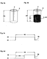
- Figure 4a shows an empty product receiving device 5 in a highly schematic perspective representation obliquely from above.
- the product receiving device 5 is, for example, a cylindrical vessel made of a transparent material and is particularly suitable for receiving a liquid product 4 .
- the product receiving device 5 is provided on one side along its fillable height H5 with a strip-shaped layer 2 of a fluorescent material, which can be provided both on the inside and on the outside due to the transparency of the vessel.
- Figure 4b shows the product receiving device 5 from FIG Figure 4a with a product quantity 40 of a liquid product 4 received up to a filling level H4, which can cover the layer 2 according to its optical properties and corresponding to its filling level H4 or can attenuate the emitted light, which is detected in each case by the sensor 3 described below.
- FIG 1 can be arranged at appropriate positions in front of the product receiving device 5, so that by means of Sensor 3, the light emitted by layer 2 can be detected, which is also the case for the following based on Figures 5a to c described product receiving device applies.
- Figures 4c and 4d each show brightness curves 30 of the product receiving devices 5 from FIG Figures 4a and 4b emitted and correspondingly detected light, each of which essentially corresponds to the brightness curves 30 of Figures 3c and 3d correspond, which is why reference is made here to their description.
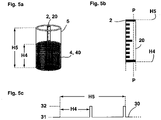
- Figure 5a shows a product receiving device 5, which is essentially the product receiving device 5 of Figures 4a and 4b corresponds, which is why reference is made here to their description.
- the product receiving device 5 of Figure 5a is like the product pick-up devices 5 of Figure 4b filled up to a filling level H4 with a product quantity 40 of a product 4.
- the strip-shaped layer 2 along the fillable height H5 of the product receiving device 5 from Figure 5a includes as opposed to Figure 4a a measuring strip 20 on which a scale made of fluorescent material can be provided.
- Figure 5b shows an enlarged representation of the in Figure 5a exposed measuring strip 20 with its layer 2 applied as a scaling.
- Figure 5c shows a brightness curve 30 of a profile along the line PP of FIG Figure 5b of the product receiving device 5 of Figure 5a emitted and correspondingly detected light, with two brightness maxima 32, which are detected by the profile P.
- Both the gage 20 from Figures 5a and 5b as well as the corresponding strip-shaped layer 2 of the execution of Figures 4a and 4b can be provided directly on the respective product receiving device 5, as well as be designed as an independent element.
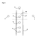
- FIG 6 shows a schematic representation of a product receiving device 5 with products 4 arranged on it, the product receiving device 5 being a conveyor belt, for example of a product warehouse.
- light sources 1 are arranged opposite one another laterally of the product receiving device 5 according to FIG 1 arranged which irradiate/illuminate a detection area 50 particularly well while avoiding unwanted shadows.
- Above the detection area 50 is an optical sensor 3 provided with a filter device according to FIG 1 arranged. The corresponding drawing of the filter device was omitted here.
- the products 4 cover the fluorescent layer on the surface of the product receiving device 5 and are recognized by the sensor 3 as a dark outline.
- the identified products 4 can be assigned using stored reference images of the products 4 and can be counted using a suitable software routine.
- the figure 7 shows a top view of a spindle holder A1, as can be used in the vending machine according to the invention (not shown).
- Several goods A2 are attached to the spindle holder A1.
- the goods A2 are razor blades whose packaging is a so-called Euroslot exception.
- An optical sensor in this case a camera (not shown), is arranged above the spindle rod A1 and records image data from the perspective shown.
- a brightness curve A3 is shown to the left of the spindle rod A1, which was calculated by the control unit from the image data of the camera. Gaps between two goods can be deduced from the brightness maxima A4. The brightness minima A5 can be assigned to the goods A2. The number of goods A2 suspended on the spindle rod A1 can therefore be determined on the basis of the brightness curve A3.
- FIG 8 several chutes A7 of a vending machine (not shown) are shown.
- Goods A2' are stored in different numbers in the individual goods chutes A7, A7', A7".
- the goods A2' are packets of cigarettes.
- Image data from several goods chutes can be recorded simultaneously by the camera.
- To the right of the goods chutes A7, A7', A7" shows a schematic brightness curve A3' of the first product chute A7'.
- the number of goods A2' can be determined from the number of brightness minima A5.
- the control unit can simultaneously calculate a number of brightness curves A3' from the image data and assign these to the respective product chutes A7, A7', A7".
- A7" can be determined.
Landscapes
- Business, Economics & Management (AREA)
- Accounting & Taxation (AREA)
- General Physics & Mathematics (AREA)
- Physics & Mathematics (AREA)
- Economics (AREA)
- Engineering & Computer Science (AREA)
- Marketing (AREA)
- Human Resources & Organizations (AREA)
- Entrepreneurship & Innovation (AREA)
- Operations Research (AREA)
- Quality & Reliability (AREA)
- Strategic Management (AREA)
- Tourism & Hospitality (AREA)
- Development Economics (AREA)
- General Business, Economics & Management (AREA)
- Finance (AREA)
- Theoretical Computer Science (AREA)
- Control Of Vending Devices And Auxiliary Devices For Vending Devices (AREA)
Description
- Die Erfindung betrifft einen Warenautomaten, der für den Abverkauf verschiedener Waren eingesetzt werden kann und ein Verfahren zum Betreiben eines derartigen Warenautomaten, sowie ein Verfahren zur Produktbestandsermittlung und insbesondere ein optisches Verfahren zur Produktbestandsermittlung.
- Derartige Warenautomaten werden zur Ausgabe von Waren, vornehmlich in der Nähe einer Kassenzone, eingesetzt.
- Die
DE 10 2012 102 942 A1 zeigt einen Warenautomaten, der mehrere Warenschächte aufweist, die jeweils über einen eigenen Leerstandssensor verfügen. Wenn die Ware in einem Warenschacht zur Neige geht, wird rechtzeitig ein Signal ausgegeben, so dass noch vor einem drohenden Leerstand der betreffende Warenschacht wieder aufgefüllt werden kann. - Die Anzahl der benötigten Sensoren muss der Anzahl der Warenschächte des Warenautomaten entsprechen. Außerdem müssen die einzelnen Warenschächte immer mit denselben Sorten von Waren befüllt sein, damit eine Steuereinheit die Leerstandinformation mit einer bestimmten Ware verknüpfen kann.
- Aus der
DE 10 2012 102 942 ein Warenautomat bekannt, der mehrere Warenschächte aufweist, die jeweils über einen eigenen Leerstandssensor verfügen. Wenn die Ware in einem Warenschacht zur Neige geht, wird rechtzeitig ein Signal ausgegeben, so dass noch vor einem drohenden Leerstand der betreffende Warenschacht wieder aufgefüllt werden kann. Der Warenautomat benötigt dafür jedoch für jeden einzelnen Warenschacht einen eigenen Sensor, was entsprechend kostspielig ist. Außerdem müssen die einzelnen Warenschächte immer mit denselben Sorten von Waren befüllt sein, damit eine Steuereinheit die Leerstandsinformation mit einer bestimmten Ware verknüpfen kann, was einen flexiblen Betrieb des Warenautomaten erheblich einschränkt. - Aus der
US 2013/0151006 A1 ist ein Warenautomat bekannt, bei dem Bilddaten einer auszugebenden Ware an ihrer Ausgabelokation erfasst und Bilddaten aus einer Datenbank zugeordnet werden. Diese Information wird an eine von dem Warenautomaten entfernte Basisstation gesendet, die diese Information weiter verarbeitet, wonach Informationen über den Warenbestand lediglich an der Basisstation zur Verfügung stehen. Bei Leerstand wird an dem Warenautomat ein Bild einer leeren Ausgabelokation erfasst und ein entsprechender Leerstand detektiert. Eine Warenspeichereinheit des Warenautomatens wird daher anders als bei der vorstehendenDE 10 2012 102 942 A1 nachteilhaft erst nach einem detektierten Leerstand wieder aufgefüllt. - Die Aufgabe der Erfindung besteht darin einen kostengünstigen Warenautomaten vorzuschlagen, der für den Abverkauf verschiedener Waren eingesetzt werden kann, sowie ein Verfahren zum Betreiben eines derartigen Warenautomatens anzugeben. Die Aufgabe der vorliegenden Erfindung ist dabei außerdem ein kostengünstiges, flexibel einsetzbares und dennoch zuverlässiges Verfahren zur Produktbestandsermittlung anzugeben
- Die Aufgabe wird durch den Gegenstand des unabhängigen Anspruchs 1 gelöst.
- Vorteilhafte Ausgestaltungen der Erfindung sind in den Unteransprüchen angegeben.
- Der erfindungsgemäße Warenautomat weist zumindest eine Warenspeichereinheit auf, in welcher eine Vielzahl gleichartiger oder unterschiedlicher Waren gespeichert sein kann.
- Bei der Warenspeichereinheit handelt es sich um Spindelstangen, auf denen jeweils eine Vielzahl von einzelnen Waren aufgehängt sind. Bei den Waren handelt es sich beispielsweise um Rasierklingen. Auf den einzelnen Spindelstangen können jeweils unterschiedliche Sorten von Rasierklingen hängen. Die Spindelstangen können aber auch sortenrein ausgeführt sein. In diesem Fall würde sich auf jeder Spindelstange nur eine Sorte von Rasierklingen befinden.
- Neben der Warenspeichereinheit weist der Warenautomat eine Steuereinheit auf. Die Steuereinheit kann die gesamten Verkaufsabläufe des Warenautomaten steuern. Die Steuereinheit ist in der Lage mit der geeigneten Software weitere Auswertungen und Berechnungen durchzuführen. Die Steuereinheit umfasst einen Speicher bzw. einen Speicherbaustein, auf welchem unterschiedliche Informationen gespeichert werden können.
- Der Warenautomat weist einen optischen Sensor auf, mit dem Bilddaten erfasst werden. Diese Bilddaten beinhalten Helligkeitsunterschiede eines aufgenommenen Bilds bzw. eines aufgenommenen Bereichs. Aus den Bilddaten wird von der Steuereinheit eine Helligkeitskurve mit Helligkeitsminima und Helligkeitsmaxima errechnet. Die Steuereinheit ermittelt aus der Anzahl der Helligkeitsminima die Anzahl der Waren, die sich in der Warenspeichereinheit befinden. Die Bilddaten des optischen Sensors beinhalten auch Freiräume zwischen den einzelnen Waren
- Vorteilhafterweise handelt es sich beim optischen Sensor um eine Kamera. Kameras können günstig erworben und auch bei bestehenden Warenautomaten nachgerüstet werden. Die Kamera kann verfahrbar im Warenautomaten angeordnet sein. Je nachdem welchen Bildausschnitt die Kamera erfassen kann, kann es sinnvoll sein die Kamera an Positionen fahren zu lassen um weitere Bildausschnitte zu erfassen, um beispielsweise ein Gesamtbild eines Warenlagerbereichs zu erlangen. Dadurch kann vermieden werden, dass mehrere Kameras eingebaut werden müssen.
- Der optische Sensor zeichnet Bilddaten der zumindest einen Warenspeichereinheit und der darin befindlichen Waren auf. Aus den Bilddaten des optischen Sensors ermittelt die Steuereinheit mithilfe einer geeigneten Softwareroutine die Anzahl der Waren, die sich in der zumindest einen Warenspeichereinheit befinden.
- Der Warenautomat kann einen nicht beanspruchten Komparator aufweisen. Mithilfe des Komparators können vom optischen Sensor erfasste Bilddaten mit im Speicherbaustein gespeicherten Referenzbildern verglichen werden.
- Bei der Auswertung der Bilddaten des optischen Sensors werden Helligkeitsunterschiede ausgewertet. Dadurch können freie Stellen vor und zwischen zwei nebeneinander angeordneten Waren detektiert werden. Dadurch kann die Anzahl der in einer Warenspeichereinheit befindlichen Waren detektiert werden.
- Der Warenautomat kann mehrere Warenspeichereinheiten aufweisen. In diesem Fall ermittelt die Steuereinheit aus den Bilddaten des optischen Sensors die Anzahl der Warenspeichereinheiten und gleichzeitig die Anzahl der jeweils darin befindlichen Waren. Auch bei den Warenspeichereinheiten werden hierfür die Helligkeitsunterschiede zwischen den Warenspeichereinheiten ausgenutzt.
- Auf der Steuereinheit kann zumindest ein Referenzbild zumindest einer Ware gespeichert sein. Die Steuereinheit kann anhand dieses zumindest einen Referenzbildes und der Bilddaten des optischen Sensors die Anzahl der in zumindest einer Warenspeichereinheit gespeicherten Waren ermitteln. Durch das Referenzbild einer Ware kann speziell diese Ware sehr zuverlässig durch Bildvergleiche von dem optischen Sensor detektiert werden. In diesem Fall kann die Anzahl der Waren genau dieser Sorte in der Warenspeichereinheit ermittelt werden. Weiterhin kann durch ein Ausschlussprinzip die Anzahl der Waren ermittelt werden, die genau nicht diese Sorte betrifft.
- Auf der Steuereinheit können mehrere Referenzbilder unterschiedlicher Waren gespeichert sein. Die Steuereinheit kann anhand dieser Referenzbilder und der Bilddaten des optischen Sensors die Anzahl der unterschiedlichen Waren in zumindest einer Warenspeichereinheit ermitteln. So kann erfasst werden welche Sorten von Waren in welcher Anzahl in einer Warenspeichereinheit gespeichert sind.
- Auf der Steuereinheit können mehrere Referenzbilder unterschiedlicher Waren und zumindest ein Referenzbild einer Warenspeichereinheit gespeichert sein. Die Steuereinheit kann anhand dieser Referenzbilder und der Bilddaten des optischen Sensors die Anzahl der Warenspeichereinheiten und die Anzahl der darin befindlichen Waren ermitteln. Diese Lösung empfiehlt sich, wenn der Warenautomat mehrere Warenspeichereinheiten aufweist, die in etwa baugleich ausgeführt sind.
- Auf der Steuereinheit können mehrere Referenzbilder unterschiedlicher Waren und mehrere Referenzbilder unterschiedlicher Warenspeichereinheiten gespeichert sein. Die Steuereinheit kann anhand dieser Referenzbilder und der Bilddaten des optischen Sensors die Anzahl der Warenspeichereinheiten und die Anzahl der darin befindlichen Waren ermitteln. Diese Lösung ist besonders interessant, wenn der Warenautomat unterschiedliche Warenspeichereinheiten aufweist. Diese Variante kann auch als Nachrüstlösung vom Hersteller zur Verfügung gestellt werden. Wenn alle unterschiedlichen Warenspeichereinheits-Referenzbilder gespeichert sind, kann ein und dieselbe Hardware mit dem entsprechenden Speicherbaustein bei verschiedenen Warenautomaten nachgerüstet werden.
- Der Warenautomat kann einen nicht beanspruchten Komparator zum Vergleich von Referenzbildern mit den Bilddaten aufweisen. Der Komparator kann als separates Bauteil oder als Softwareroutine ausgeführt sein.
- Die Begriffe Produkte und Waren werden bei der vorliegenden Patentanmeldung synonym verwendet.
- Die vorliegende Erfindung betrifft wie beansprucht ein erfindungsgemäßes Verfahren zur Produktbestandsermittlung einer Vielzahl von Produkten und/oder einer Produktmenge zumindest einer Produktaufnahmevorrichtung unter Verwendung zumindest einer Lichtquelle, die UV-Licht eines vorbestimmten ersten Wellenlängenbereichs ausstrahlt, wobei die Produktaufnahmevorrichtung eine Schicht mit fluoreszierenden Eigenschaften umfasst, die Licht mit einer vorbestimmten zweiten Wellenlänge innerhalb eines vorbestimmten zweiten Wellenlängenbereichs emittiert, und unter Verwendung zumindest eines mit einer Filtereinrichtung ausgestatteten optischen Sensors, mittels dem ausschließlich Licht des vorbestimmten zweiten Wellenlängenbereichs erfasst wird, wobei der optische Sensor Bilddaten der zumindest einen Produktaufnahmevorrichtung und ihrer Produkte und/oder ihrer Produktmenge aufzeichnet.
- Bei der Lichtquelle handelt es sich vorzugsweise um eine schmalbandige Lichtquelle, beispielsweise ein Laser oder eine LED-Lampe. Bei dem optischen Sensor handelt es sich vorteilhafterweise um einen Liniendetektor.
- Mittels außerdem der Verwendung einer Steuereinheit kann dabei aus den Bilddaten des optischen Sensors der Produktbestand der zumindest einen Produktaufnahmevorrichtung besonders einfach, zuverlässig und kostengünstig ermittelt werden.
- Das ist insbesondere deshalb der Fall, weil ein auf der Schicht mit fluoreszierenden Eigenschaften angeordnetes Produkt von einem geeigneten optischen Sensor besonders zuverlässig erkannt werden kann. Zwischen dem jeweils von dem Produkt reflektiertem Licht und von der fluoreszierenden Schicht emittiertem Licht tritt nämlich ein wünschenswert hoher Kontrast auf.
- Hierbei kann die Steuereinheit aus den Bilddaten des optischen Sensors auf besonders einfache und zuverlässige Weise Helligkeitskurven ermitteln, die einen Pulsverlauf mit vorteilhaft digitalem Charakter aufweisen. Aus diesem Grund lassen sich hieran anschließend aus den ermittelten Helligkeitskurven ebenfalls besonders einfach und somit kostengünstig und außerdem besonders zuverlässig über eine Analyse deren Maxima und Minima mittels einer Softwareroutine eine Bestandsermittlung der Produkte und/oder einer Produktmenge und damit insbesondere auch eine Produktzählung durchführen.
- Der optische Sensor kann dabei geeigneter Weise eine Kamera sein, die mit einer geeigneten Filtereinrichtung ausgestattet ist. Kameras können günstig erworben und auf einfache Weise nachgerüstet werden. Eine geeignete Filtereinrichtung kann ebenfalls zuverlässig und kostengünstig mittels einer Softwareroutine bereitgestellt werden. Besonders vorteilhaft ist hierbei, wenn auf einfache Weise ein Wellenlängenbereich kleiner als der vorbestimmte von dem Sensor erfasste zweite Wellenlängenbereich ausgeblendet wird.
- Hierbei ist besonders vorteilhaft, wenn der von dem Sensor erfasste zweite vorbestimmte Wellenlängenbereich Licht mit einer Wellenlänge von größer als 600nm umfasst, nachdem nicht nur UV-Licht, sondern auch Licht im sichtbaren Bereich ausgeblendet wird und ein möglichst großer Abstand zwischen dem von dem Sensor erfassten Licht und dem von der Lichtquelle ausgestrahltem Licht vorhanden ist. Hierdurch werden insbesondere auch unerwünschte Störungen minimiert.
- Die Schicht mit fluoreszierenden Eigenschaften kann nämlich auch Schwankungen in ihrer Mächtigkeit und/oder ihrer Materialbestandteile und damit ihrer optischen Eigenschaften aufweisen, wonach ein vollständiges Ausblenden von Licht mit einer Wellenlänge kleiner 600nm und dabei vollständigem Erfassen von Licht mit einer Wellenlänge größer 600nm zur Minimierung diesbezüglicher möglicher Störeffekte besonders vorteilhaft ist. In diesem Zusammenhang ist klar, dass für ein Material der Schicht mit fluoreszierenden Eigenschaften ein geeignetes fluoreszierendes Material ausgewählt wird.
- Ein besonders starker vorstehender Kontrast lässt sich dabei erzielen, wenn mittels der Lichtquelle im wesentlichen Licht einer vorbestimmten diskreten ersten Wellenlänge des ersten Wellenlängenbereichs im UV-Spektralbereich ausgestrahlt wird, wobei die vorbestimmte erste Wellenlänge insbesondere zwischen 350nm und 400nm liegt und insbesondere etwa bei 375nm liegt. Außerdem ist eine ausgestrahlte erste Wellenlänge dieses Bereichs von dem vorstehenden erfassten zweiten Wellenlängenbereich wünschenswert weit beabstandet.
- Ein vorstehendes erfindungsgemäßes Verfahren zur Produktbestandsermittlung lässt sich wie vorstehend gesagt außerdem auch auf einfache und zuverlässige Weise als Verfahren zur Produktzählung einsetzen.
- Geeigneter Weise kann die Schicht mit fluoreszierenden Eigenschaften auf einer Oberfläche der Produktaufnahmevorrichtung zur Aufnahme der Vielzahl von Produkten und/oder der Produktmenge ausgebildet sein. Hierdurch wird die Möglichkeit geschaffen, Produktaufnahmevorrichtungen beispielsweise mittels einer geeigneten Lackierung mit jeweils individuellen an sie angepassten Schichten zu versehen, so dass deren Funktionsumfang nicht behindert wird. Außerdem lassen sich auf diese Weise Produktaufnahmevorrichtungen kostengünstig nachrüsten.
- Mittels einer Schicht, die auf einem, insbesondere auch als unabhängiges Element ausgebildeten, Messstreifen vorgesehen ist, kann dazu alternativ eine Möglichkeit geschaffen werden, eine Produktaufnahmevorrichtung auf einfache Weise individuell und flexibel nachzurüsten. Ein derartiger Messstreifen kann dabei außerdem optisch detektierbare Informationen wie beispielsweise eine Skalierung umfassen, die insbesondere eine wünschenswert genaue Ermittlung einer Produktmenge ermöglicht. Ein derartiger Messstreifen kann beispielsweise mittels einem mit einer Schicht mit fluoreszierenden Eigenschaften versehenen Metall- oder Kunststoffelement bereitgestellt werden.
- Die vorliegende Erfindung betrifft demnach insbesondere auch eine für ein vorstehendes Verfahren geeignete Produktaufnahmevorrichtung zur Aufnahme einer Vielzahl von Produkten und/oder einer Produktmenge. Eine vorstehende erfindungsgemäße Produktaufnahmevorrichtung ist dabei für den Betrieb in einem Produktautomaten besonders geeignet.
- Die vorliegende Erfindung betrifft außerdem eine Produktzähleinrichtung mit wenigstens einer UV-Lichtquelle und mit wenigstens einem optischen Sensor, der eine Filtereinrichtung umfasst, und mit einer Steuereinheit zur Ermittlung eines Produktbestands. Die UV-Lichtquelle und/oder der optische Sensor können dabei verfahrbar angeordnet sein. Die Steuereinheit kann die gesamten Abläufe der Produktzähleinrichtung steuern. Insbesondere kann mittels der Steuereinheit die UV-Lichtquelle und/oder der optische Sensor geschwenkt und/oder in eine geeignete Position gebracht werden. Die Steuereinheit ist dabei in der Lage mit der geeigneten Software weitere Auswertungen und Berechnungen durchzuführen. Die Steuereinheit umfasst außerdem einen Speicher bzw. einen Speicherbaustein, auf dem unterschiedliche Informationen gespeichert werden können.
- Auf diese Weise ist die Produktzähleinrichtung geeignet ausgebildet, die Anzahl der Produkte und/oder die Produktmenge insbesondere eines Produktautomaten mit wenigstens einer erfindungsgemäßen Produktaufnahmevorrichtung zu zählen, wonach die Produktzähleinrichtung außerdem geeignet ausgebildet ist, ein vorstehendes erfindungsgemäßes Verfahren auszuführen.
- Eine vorteilhafte Produktzähleinrichtung umfasst dabei insbesondere vorteilhaft eine optische Filtereinrichtung, die mittels Software bereitgestellt ist, und die einen Wellenlängenbereich kleiner dem vorbestimmten zweiten Wellenlängenbereich ausblendet.
- Zur Durchführung einer individuellen Produktzählung auch unterschiedlicher Produkte kann insbesondere auf der Steuereinheit der Produktzähleinrichtung wenigstens ein Referenzbild wenigstens eines Produkts gespeichert sein. Zur Durchführung einer Produktzählung einer Vielzahl von Produkten in einer Vielzahl von Produktaufnahmevorrichtungen kann auf der Steuereinheit der Produktzähleinrichtung insbesondere vorteilhaft außerdem wenigstens ein Referenzbild wenigstens einer Produktaufnahmevorrichtung gespeichert sein.
- Ein Ausführungsbeispiel der Erfindung ist in den Zeichnungen dargestellt und wird im Folgenden näher erläutert.
Figuren 3 bis 6 und8 sind weitere Beispiele von nicht-erfindungsgemäβen Produktaufnahmevorrichtungen. - Es zeigen:
- Fig. 1a - c
- jeweils schematische, erläuternde Darstellungen eines grundlegenden Gedankens einer Ausführung der Erfindung;
- Fig. 2a
- jeweils unterschiedlich befüllte Produktaufnahmevorrichtungen nach einer Ausführung der Erfindung;
- Fig. 2b - d
- jeweils eine Helligkeitskurve des von den Produktaufnahmevorrichtungen von
Fig. 2a emittierten und entsprechend detektierten Lichts; - Fig. 3a - b
- eine jeweils unterschiedlich befüllte Produktaufnahmevorrichtung;
- Fig. 4a - b
- eine jeweils unterschiedlich befüllte Produktaufnahmevorrichtung;
- Fig. 5a
- eine unvollständig befüllte Produktaufnahmevorrichtung;
- Fig. 5b
- eine vergrößerte Darstellung eines Elements der Produktaufnahmevorrichtung von
Fig. 5a ; - Fig. 5c
- eine Helligkeitskurve des von der Produktaufnahmevorrichtung von
Fig. 5a emittierten und entsprechend detektierten Lichts; - Fig. 6
- eine schematische Darstellung einer Produktaufnahmevorrichtung mit auf ihr angeordneten Produkten;
- Fig. 7
- eine leicht perspektivische Draufsicht auf einen Spindelhalter eines Warenautomaten mit daran angehängten Waren und
- Fig. 8
- eine Draufsicht auf mehrere Warenschächte eines Warenautomaten mit darin in unterschiedlicher Anzahl gespeicherten Waren.
- Die Figuren enthalten teilweise vereinfachte, schematische Darstellungen. Zum Teil werden für gleiche, aber gegebenenfalls nicht identische Elemente identische Bezugszeichen verwendet. Verschiedene Ansichten gleicher Elemente könnten unterschiedlich skaliert sein.
-
Fig. 1a zeigt eine schematische, erläuternde Darstellung eines grundlegenden Gedankens einer Ausführung der Erfindung, wonach mittels einer UV Lichtquelle 1 Licht eines vorbestimmten ersten Wellenlängenbereichs λ10 und insbesondere Licht einer Wellenlänge λ1 auf eine Produktaufnahmevorrichtung 5 ausgestrahlt wird, auf der ein Produkt 4 angeordnet ist. Die Produktaufnahmevorrichtung 5 umfasst auf Ihrer Oberfläche eine Schicht 2 mit fluoreszierenden Eigenschaften, wobei ein Teil der Schicht 2 von dem Produkt 4 verdeckt wird. Das von dem Produkt 4 reflektierte Licht liegt dabei ebenfalls in dem ersten Wellenlängenbereich λ10. Andererseits ist das von der Schicht 2 der Produktaufnahmevorrichtung 5 emittierte Licht gemäß der inFig. 1b dargestellten Stokesschen Verschiebung zu einer Wellenlänge λ2 innerhalb eines energieärmeren Wellenlängenbereichs λ20 verschoben. - Das von dem Produkt 4 reflektierte Licht und das von der Schicht 2 emittierte Licht wird von einem optischen Sensor 3 erfasst, wobei der optische Sensor 3 eine Filtereinrichtung 33 umfasst, die Licht des ersten Wellenlängenbereichs λ10 und insbesondere der ersten Wellenlänge λ1 ausblendet. Demnach wird von dem optischen Sensor 3 lediglich von der Schicht 2 der Produktaufnahmevorrichtung 5 reflektiertes Licht des zweiten Wellenlängenbereichs λ20 detektiert und dabei ein wünschenswert hoher Kontrast zwischen Produkt 4 und Produktaufnahmevorrichtung 5 erzielt. Die Lichtquelle 1 und der optische Sensor 3 sind dabei an geeigneten Positionen oberhalb der Produktaufnahmevorrichtung 5 angeordnet.
-
Fig. 1c zeigt hierzu eine von einer Steuereinheit aus Bilddaten des Sensors 3 ermittelte Helligkeitskurve 30 entlang eines Profils in Längsrichtung der Produktaufnahmevorrichtung 5. Die Helligkeitskurve 30 hat einen vorteilhaft pulsförmigen Verlauf mit digitalem Charakter mit zwei ausgeprägten Helligkeitsmaxima 32, die die Schicht 2 kennzeichnen und einem Helligkeitsminimum 31, das von dem Produkt 4 verursacht wird. Anhand der Helligkeitskurve 30 kann daher die Anzahl der von der Produktaufnahmevorrichtung 5 aufgenommenen Produkte 4 ermittelt werden. -
Fig. 2a zeigt drei jeweils unterschiedlich befüllte Produktaufnahmevorrichtungen 5 nach einer Ausführung der Erfindung mit einer auf ihrer Oberfläche ausgebildeten Schicht 2 mit fluoreszierenden Eigenschaften in perspektivischer Darstellung aus einer nicht ganz senkrechten Ansicht von oben. - Die Produktaufnahmevorrichtungen 5 sind jeweils als Spindelhalter ausgebildet und erstrecken sich von beispielsweise einem Produktautomaten oder einer Produktlagervorrichtung ausgehend im Wesentlichen horizontal. Die linke Produktaufnahmevorrichtung 5 trägt ein Produkt 4, und die auf gleichem Niveau ausgebildete rechte Produktaufnahmevorrichtung 5 trägt fünf Produkte 4.
- Die mittige Produktaufnahmevorrichtung 5 ist leer und auf einem vergleichsweise niedrigeren Niveau angeordnet.
- Die Produkte 4 sind jeweils auf übliche Weise mit gleichartigen Verpackungen versehen, die auf bekannte Weise mit den Spindelhaltern zusammenwirken.
- Eine in
Fig. 2a nicht dargestellte UV-Licht ausstrahlende Lichtquelle kann zu den Produktaufnahmevorrichtungen 5 vonFig. 2a an einer Position angeordnet sein, die in etwa einer vorstehend beschriebenen Position der Lichtquelle 1 vonFig. 1 entspricht, und ein, inFig. 2a ebenfalls nicht dargestellter, geeigneter optischer Sensor kann ebenfalls an einer Position angeordnet sein, die in etwa einer vorstehend beschriebenen Position des Sensors 3 vonFig. 1 entspricht. Die Positionen der Lichtquelle 1 und des optischen Sensors 3 sind dabei geeignet, die drei Produktaufnahmevorrichtungen 5 vonFig. 2a mit den Produkten 4 mittels lediglich einer Lichtquelle 1 zu bestrahlen und mittels lediglich einem Sensor 3 zu erfassen. - Die
Fig. 2b, 2c und 2d zeigen jeweils eine Helligkeitskurve 30 eines Profils des von den Produktaufnahmevorrichtungen 5 vonFig. 2a emittierten und entsprechend von dem optischen Sensor 3 detektierten Lichts in Längsrichtung der Produktaufnahmevorrichtungen 5. Die Kurven der Helligkeitsverläufe 30 der Produktaufnahmevorrichtungen 5 haben dabei alle einen vorteilhaft pulsförmigen Verlauf mit digitalem Charakter zwischen einem detektierten Maximum 32, das die Schicht 2 kennzeichnet, und Minimum 31 entsprechend der Anzahl der jeweils vorhandenen Produkte 4. Die beiden Enden der Schicht 2 der Produktaufnahmevorrichtungen 5 in Profilrichtung sind dabei ebenfalls durch ein jeweiliges Minimum 31 gekennzeichnet. Je nach Perspektive der jeweils erfassten Produkte 4 auf den Produktaufnahmevorrichtungen 5 können dabei die Minima der Produkte 4 entsprechend unterschiedliche Pulsbreiten haben und sind dabei dennoch zur Ermittlung der Anzahl der Produkte 4 geeignet. -
Fig. 3a zeigt eine leere Produktaufnahmevorrichtung 5 in stark schematischer perspektivischer Darstellung von schräg vorn. Die Produktaufnahmevorrichtung 5 ist als Rahmen eines Produktschachts eines Produktautomaten oder einer Produktlagervorrichtung ausgebildet. - Die Produktaufnahmevorrichtung 5 hat eine befüllbare Höhe H5 und ist nach vorne und nach oben hin offen. An die Produktaufnahmevorrichtung 5 kann sich nach unten beispielsweise eine Produktausgabevorrichtung anschließen. Die Produktaufnahmevorrichtung 5 ist außerdem an der Vorderseite ihres Rahmens und an der rückseitigen Wand ihres Rahmens innenseitig mit einer Schicht 2 mit fluoreszierenden Eigenschaften versehen.
-
Fig. 3b zeigt die Produktaufnahmevorrichtung 5 vonFig. 3a mit drei von ihr aufgenommenen gleichartigen Produkten 4. Die Produkte 4 haben dabei einen Füllstand H4. Außerdem verdecken die Produkte 4 entsprechend ihren Abmessungen bzw. des Füllstands H4 die innenseitige Schicht 2 auf der rückseitigen Wand. - Eine für die Anwendung des Verfahrens zur Produktbestandsermittlung geeignete Lichtquelle 1 und ein geeigneter Sensor 3 gemäß
Fig. 1 kann vor dem offenen Schacht der Produktaufnahmevorrichtung 5 an jeweils geeigneten Positionen angeordnet werden, so dass mittels dem Sensor 3 das von der Schicht 2 emittierte Licht detektiert werden kann. -
Fig. 3c zeigt hierzu den Helligkeitsverlauf 30 eines Profils der befüllbaren Höhe 5 des von der leeren Produktaufnahmevorrichtung 5 vonFig. 3a emittierten Lichts, der im Wesentlichen dem vorstehend beschriebenen Helligkeitsverlauf 30 vonFig. 2c entspricht, weshalb hier auf die diesbezügliche Beschreibung verwiesen wird. -
Fig. 3d zeigt den Helligkeitsverlauf 30 eines Profils der befüllbaren Höhe H5 des von der Produktaufnahmevorrichtung 5 vonFig. 3b emittierten und von dem Sensor 3 detektierten Lichts mit einer entsprechend dem Füllstand H4 gegenüber dem Maximum 32 vonFig. 3c reduzierten Pulsbreite dessen Helligkeitsmaximums 32. Aus der Ermittlung der Pulsbreite des Helligkeitsmaximums 32 kann daher der Füllstand H4 der Produktaufnahmevorrichtung 5 vonFig. 3a und b bestimmt werden, und daraus dann auch die Anzahl der aufgenommenen Produkte 4 bestimmt werden. - Außerdem kann eine Vielzahl von unterschiedlichen, insbesondere auch nebeneinander angeordneten Produktaufnahmevorrichtungen 5 mittels Analyse eines Helligkeitsverlaufs eines entsprechenden Querprofils aus den jeweiligen Helligkeitsmaxima der Rahmen oder auch aus Vergleichen mit gespeicherten Referenzbildern erkannt werden.
-
Fig. 4a zeigt eine leere Produktaufnahmevorrichtung 5 in stark schematischer perspektivischer Darstellung von schräg oben. Die Produktaufnahmevorrichtung 5 ist ein beispielsweise zylindrisches Gefäß aus einem transparenten Material und besonders geeignet, ein flüssiges Produkt 4 aufzunehmen. - Die Produktaufnahmevorrichtung 5 ist an einer Seite entlang ihrer befüllbaren Höhe H5 mit einer streifenförmigen Schicht 2 eines fluoreszierenden Materials versehen, die aufgrund der Transparenz des Gefäßes sowohl innenseitig als auch außenseitig vorgesehen sein kann.
-
Fig. 4b zeigt die Produktaufnahmevorrichtung 5 vonFig. 4a mit einer bis zu einem Füllstand H4 aufgenommenen Produktmenge 40 eines flüssigen Produkts 4, das die Schicht 2 entsprechend seinen optischen Eigenschaften und entsprechend seinem Füllstand H4 verdecken kann oder deren emittiertes Licht dämpfen kann, was jeweils von dem nachfolgend beschriebenen Sensor 3 erkannt wird. - Eine für die Anwendung des Verfahrens zur Produktbestandsermittlung geeignete Lichtquelle 1 und ein geeigneter Sensor 3 gemäß
Fig. 1 kann an jeweils geeigneten Positionen vor der Produktaufnahmevorrichtung 5 angeordnet werden, so dass mittels dem Sensor 3 das von der Schicht 2 emittierte Licht detektiert werden kann, was so auch für die nachfolgende anhand vonFig. 5a bis c beschriebene Produktaufnahmevorrichtung gilt. -
Fig. 4c und 4d zeigen jeweils Helligkeitskurven 30 des von den Produktaufnahmevorrichtungen 5 vonFig. 4a und 4b emittierten und entsprechend detektierten Lichts, die im Wesentlichen jeweils den Helligkeitskurven 30 vonFig. 3c und 3d entsprechen, weshalb hier auf deren Beschreibung verwiesen wird. -
Fig. 5a zeigt eine Produktaufnahmevorrichtung 5, die im Wesentlichen der Produktaufnahmevorrichtung 5 vonFig. 4a und 4b entspricht, weshalb hier auf deren Beschreibung verwiesen wird. - Die Produktaufnahmevorrichtung 5 von
Fig. 5a ist wie die Produktaufnahmevorrichtungen 5 vonFig. 4b bis zu einem Füllstand H4 mit einer Produktmenge 40 eines Produkts 4 befüllt. Die streifenförmige Schicht 2 entlang der befüllbaren Höhe H5 der Produktaufnahmevorrichtung 5 vonFig. 5a umfasst im Unterschied zuFig. 4a einen Messstreifen 20 auf der eine Skalierung aus fluoreszierendem Material vorgesehen sein kann. -
Fig. 5b zeigt hierzu eine vergrößerte Darstellung des inFig. 5a freiliegenden Messstreifens 20 mit seiner als Skalierung aufgetragenen Schicht 2. Mittels der vorteilhaften Skalierung kann ein Füllstand H4 der befüllbaren Höhe H5 besonders genau detektiert werden. -
Fig. 5c zeigt hierzu eine Helligkeitskurve 30 eines Profils entlang der Linie P-P vonFig. 5b des von der Produktaufnahmevorrichtung 5 vonFig. 5a emittierten und entsprechend detektierten Lichts, mit zwei Helligkeitsmaxima 32, die von dem Profil P erfasst werden. - Sowohl der Messstreifen 20 von
Fig. 5a und 5b als auch die korrespondierende streifenförmige Schicht 2 der Ausführung vonFig. 4a und 4b können dabei direkt auf der jeweiligen Produktaufnahmevorrichtung 5 vorgesehen sein, als auch als unabhängiges Element ausgebildet sein. Zum Beispiel können Sie etwa als ein entsprechend beschichtetes Metall- oder Kunststoffelement ausgebildet sein, mit dem auf einfache Weise die Produktaufnahmevorrichtung 5 gemäßFig. 5a und4a und 4b aber auch gemäßFig. 3a und 3b ausgestattet werden können. -
Fig. 6 zeigt eine schematische Darstellung einer Produktaufnahmevorrichtung 5 mit auf ihr angeordneten Produkten 4, wobei die Produktaufnahmevorrichtung 5 ein Förderband beispielsweise eines Produktlagers ist. An geeigneten Positionen oberhalb der Produktaufnahmevorrichtung 5 sind einander seitlich der Produktaufnahmevorrichtung 5 gegenüberliegend angeordnete Lichtquellen 1 gemäßFig. 1 angeordnet, die einen Detektierbereich 50 unter Vermeidung von unerwünschten Schattenwürfen besonders gut bestrahlen/ausleuchten. Oberhalb des Detektierbereichs 50 ist ein mit einer Filtereinrichtung versehener optischer Sensor 3 gemäßFig. 1 angeordnet. Auf die entsprechende Zeichnung der Filtereinrichtung wurde hier verzichtet. - Die Produkte 4 verdecken die fluoreszierende Schicht auf der Oberfläche der Produktaufnahmevorrichtung 5 und werden von dem Sensor 3 als dunkler Grundriss erkannt. Mittels gespeicherter Referenzbilder der Produkte 4 lassen sich die erkannten Produkte 4 zuordnen und mittels einer geeigneter Softwareroutine zählen.
- Die
Figur 7 zeigt eine Draufsicht auf einen Spindelhalter A1, wie er in den erfindungsgemäßen Warenautomaten (nicht gezeigt) eingesetzt werden kann. An den Spindelhalter A1 sind mehrere Waren A2 angehängt. Bei den Waren A2 handelt es sich um Rasierklingen, deren Verpackung eine so genannte Euroslot-Ausnehmung aufweist. - Ein optischer Sensor, in diesem Fall eine Kamera (nicht gezeigt), ist oberhalb der Spindelstange A1 angeordnet und nimmt Bilddaten aus der gezeigten Perspektive auf. Zur Veranschaulichung ist links neben der Spindelstange A1 eine Helligkeitskurve A3 dargestellt, die aus den Bilddaten der Kamera von der Steuereinheit errechnet wurde. Aus den Helligkeitsmaxima A4 kann man auf Lücken zwischen zwei Waren schließen. Die Helligkeitsminima A5 können den Waren A2 zugeordnet werden. Anhand der Helligkeitskurve A3 kann also auf die Anzahl der auf der Spindelstange A1 angehängten Waren A2 ermittelt werden.
- In
Figur 8 sind mehrere Warenschächte A7 eines Warenautomaten (nicht gezeigt) dargestellt. In den einzelnen Warenschächten A7, A7', A7" sind Waren A2' in unterschiedlicher Anzahl gespeichert. Bei den Waren A2' handelt es sich in diesem Fall um Zigarettenschachteln. Von der Kamera können gleichzeitig Bilddaten von mehreren Warenschächten aufgenommen werden. Rechts neben den Warenschächten A7, A7', A7" ist eine schematische Helligkeitskurve A3' des ersten Warenschachts A7' gezeigt. Aus der Anzahl der Helligkeitsminima A5 kann die Anzahl der Waren A2' ermittelt werden. Die Steuereinheit kann aus den Bilddaten gleichzeitig mehrere Helligkeitskurven A3' berechnen und diese den jeweiligen Warenschächten A7, A7', A7" zuordnen. Aus den jeweiligen Helligkeitskurven A3' kann dann wieder jeweils die Anzahl der Waren A2' im jeweiligen Warenschacht A7, A7', A7" ermittelt werden. -
- 1
- Lichtquelle
- 2
- Schicht
- 20
- Messstreifen
- 3
- Optischer Sensor
- 30
- Helligkeitsverlauf, Helligkeitskurve
- 31
- Minimum
- 32
- Maximum
- 33
- Filter
- 4
- Produkt
- 40
- Produktmenge
- 5
- Produktaufnahmevorrichtung
- 50
- Detektierbereich
- A1
- Spindelhalter
- A2
- Ware
- A3
- Helligkeitskurve
- A4
- Helligkeitsmaxima
- A5
- Helligkeitsminima
- A7
- Warenschacht
- I
- Intensität
- S
- Stokes Verschiebung
- P
- Profil
- H5
- Befüllbare Höhe
- H4
- Füllstand
- λ10, λ20
- Wellenlängenbereich
- λ, λ1, λ2
- Wellenlänge
Claims (10)
- Verfahren zum Betreiben eines Warenautomaten mit zumindest einer als Spindelstange ausgebildeten Warenspeichereinheit (A1, 5), in welcher eine Vielzahl einzelner Waren (A2, 4) gespeichert sind, wobei der Warenautomat eine Steuereinheit und zumindest einen optischen Sensor aufweist,- wobei der optische Sensor Bilddaten der zumindest einen Warenspeichereinheit (A1, 5) und der darin befindlichen Vielzahl einzelner Waren (A2, 4) aufzeichnet,- wobei aus den Bilddaten einer Warenspeichereinheit (A1, 5) des optischen Sensors jeweils eine Helligkeitskurve (A3, 30) mit Helligkeitsminima (A5, 31) und Helligkeitsmaxima (A4, 32) von der Steuereinheit errechnet wird,- wobei die Steuereinheit aus der Anzahl der Helligkeitsminima (A5, 31) einer Helligkeitskurve (A3, 30) die Anzahl der Waren (A2, 4) ermittelt, die sich in einer Warenspeichereinheit (A1, 5) befinden,- und wobei die Steuereinheit aus den Helligkeitsmaxima (A4, 32) Freiräume zwischen den einzelnen Waren (A2, 4) identifiziert,und wobeizumindest eine Lichtquelle (1) verwendet wird, die UV-Licht mit einer vorbestimmten ersten Wellenlänge (λ1) eines vorbestimmten ersten Wellenlängenbereichs (λ10) ausstrahlt, und wobei die Warenspeichereinheit (A1, 5) eine Schicht (2) mit fluoreszierenden Eigenschaften umfasst, die Licht mit einer vorbestimmten zweiten Wellenlänge (λ2) innerhalb eines vorbestimmten zweiten Wellenlängenbereichs (λ20) emittiert, und wobeifür den optischen Sensor eine Filtereinrichtung (33) verwendet wird, mittels der ausschließlich Licht des vorbestimmten zweiten Wellenlängenbereichs (λ20) von dem Sensor erfasst wird, und wobeider optische Sensor Bilddaten eines Profils in Längsrichtung der zumindest einen Warenspeichereinheit (A1, 5) und der darin befindlichen Waren (A2, 4) aufzeichnet, und wobei die von der Steuereinheit errechneten Helligkeitskurven (A3, 30) einen pulsförmigem Verlauf mit digitalem Charakter aufweisen.
- Verfahren zum Betreiben eines Warenautomaten nach Anspruch 1,wobei der Warenautomat mehrere Warenspeichereinheiten (A1, 5) aufweist, undwobei die Steuereinheit aus den Bilddaten des optischen Sensors die Anzahl der Warenspeichereinheiten (A1, 5) und die Anzahl der jeweils darin befindlichen Waren (A2, 4) ermittelt.
- Verfahren zum Betreiben eines Warenautomaten nach Anspruch 1 oder 2, wobei
auf der zumindest einen als Spindelstange ausgebildeten Warenspeichereinheit (A1, 5) jeweils die Vielzahl von Waren (A2, 4) aufgehängt sind. - Verfahren zum Betreiben eines Warenautomaten nach einem der Ansprürche 1 bis 3, wobei
der zweite Wellenlängenbereich (λ20) energieärmer als der erste Wellenlängenbereich (λ10) ist. - Verfahren zum Betreiben eines Warenautomaten nach einem der Ansprüche 1 bis 4, wobei
der von dem optischen Sensor erfasste zweite Wellenlängenbereich (λ20) Licht mit einer Wellenlänge von größer als 600nm umfasst. - Verfahren zum Betreiben eines Warenautomaten nach einem der Ansprüche 1 bis 5, wobei
die Lichtquelle (1) im wesentlichen Licht einer vorbestimmten ersten diskreten Wellenlänge (λ1) des ersten Wellenlängenbereichs (λ10) ausstrahlt; und wobei die vorbestimmte erste Wellenlänge (λ1) zwischen 350nm und 400nm liegt und insbesondere bei etwa 375nm liegt. - Warenautomat mit zumindest einer als Spindelstange ausgebildeten Warenspeichereinheit (A1, 5), einer Steuereinheit mit einem Speicherbaustein, einem optischen Sensor zur Erfassung von Bilddaten von einer in der Warenspeichereinheit (A1, 5) befindlicher Vielzahl von Waren (A2, 4), und mit wenigstens einer Lichtquelle (1), die UV-Licht mit einer vorbestimmten ersten Wellenlänge (λ1) innerhalb eines vorbestimmten ersten Wellenlängenbereichs (λ10) auf die Warenspeichereinheit (A1, 5) ausstrahlt, wobei die Warenspeichereinheit (A1,5) eine Schicht (2) mit fluoreszierenden Eigenschaften aufweist, die Licht mit einer vorbestimmten zweiten Wellenlänge (λ2) innerhalb eines vorbestimmten zweiten energieärmeren Wellenlängenbereichs (λ20) emittiert; und mit einer Filtereinrichtung (33), die derart eingerichtet ist, dass von dem optische Sensor ausschließlich Licht des zweiten Wellenlängenbereichs (λ20) erfasst wird. wobei die Steuereinheit mittels einer geeigneten Softwareroutine eingerichtet ist, die Anzahl der Waren (A2, 4) zu ermitteln, und wobei der Warenautomat geeignet eingerichtet ist, ein Verfahren nach einem der Ansprüche 1 bis 6 auszuführen.
- Warenautomat nach Anspruch 7,
wobei
die als Spindelstange ausgebildete Warenspeichereinheit (A1, 5) zur Aufhängung der Vielzahl von Waren auf der Warenspeichereinheit (A1, 5) ausgebildet ist. - Warenautomat nach Anspruch 7 oder 8,
wobei
die Lichtquelle (1) eine schmalbandige Lichtquelle ist. - Warenautomat nach Anspruch 7, 8 oder 9,
wobei
die Filtereinrichtung (33) mittels Software bereitgestellt ist, die einen Wellenlängenbereich kleiner dem vorbestimmten zweiten Wellenlängenbereich (λ20) ausblendet.
Applications Claiming Priority (2)
| Application Number | Priority Date | Filing Date | Title |
|---|---|---|---|
| DE102017103505.2A DE102017103505A1 (de) | 2017-02-21 | 2017-02-21 | Warenautomat mit Bestandsführungsmittel |
| DE102017120179.3A DE102017120179A1 (de) | 2017-09-01 | 2017-09-01 | Verfahren zur Produktbestandsermittlung |
Publications (2)
| Publication Number | Publication Date |
|---|---|
| EP3364381A1 EP3364381A1 (de) | 2018-08-22 |
| EP3364381B1 true EP3364381B1 (de) | 2022-04-20 |
Family
ID=61526510
Family Applications (1)
| Application Number | Title | Priority Date | Filing Date |
|---|---|---|---|
| EP18000183.6A Active EP3364381B1 (de) | 2017-02-21 | 2018-02-20 | Warenautomat mit bestandsführungsmittel |
Country Status (1)
| Country | Link |
|---|---|
| EP (1) | EP3364381B1 (de) |
Citations (1)
| Publication number | Priority date | Publication date | Assignee | Title |
|---|---|---|---|---|
| US20120314059A1 (en) * | 2011-06-10 | 2012-12-13 | Franz-Josef Hoffmann | Method for dynamically detecting the fill level of a container, container therefor, and system for dynamically monitoring the fill level of a plurality of containers |
Family Cites Families (3)
| Publication number | Priority date | Publication date | Assignee | Title |
|---|---|---|---|---|
| US20070189597A1 (en) * | 2005-08-23 | 2007-08-16 | Limer Daniel J | Machine vision counting system apparatus and method |
| WO2008119192A1 (de) * | 2007-04-03 | 2008-10-09 | Ferag Ag | Vorrichtung und verfahren zum zählen und erkennen von flächigen produkten |
| US8380347B2 (en) * | 2008-10-13 | 2013-02-19 | Brent D. Garson | Method and apparatus for use in a vending machine |
-
2018
- 2018-02-20 EP EP18000183.6A patent/EP3364381B1/de active Active
Patent Citations (1)
| Publication number | Priority date | Publication date | Assignee | Title |
|---|---|---|---|---|
| US20120314059A1 (en) * | 2011-06-10 | 2012-12-13 | Franz-Josef Hoffmann | Method for dynamically detecting the fill level of a container, container therefor, and system for dynamically monitoring the fill level of a plurality of containers |
Also Published As
| Publication number | Publication date |
|---|---|
| EP3364381A1 (de) | 2018-08-22 |
Similar Documents
| Publication | Publication Date | Title |
|---|---|---|
| EP2728305B1 (de) | Verfahren und Lichtmuster zum Messen der Höhe oder des Höhenverlaufs eines Objekts | |
| EP1431707B1 (de) | Verfahren und Vorrichtung zur Erfassung von auf einem Fördermittel bewegten Objekten mittels eines optoelektronischen Sensors | |
| DE2837112A1 (de) | Geraet zur automatischen identifizierung und registrierung von flaschen verschiedener groesse und/oder gestalt | |
| DE102010037676B4 (de) | Verfahren zur Verfolgung der Farbhomogenität der Garnoberfläche und Vorrichtung zu dessen Durchführung | |
| EP2022347B1 (de) | Optische Kontrolle von Produkten der Tabak verarbeitenden Industrie | |
| EP1047917B1 (de) | Verfahren und vorrichtung zur faserlängenmessung | |
| EP1726923B1 (de) | Befüllungsprüfverfahren und -vorrichtung | |
| DE102018105060B3 (de) | System zur Überwachung der Qualität einer Klebstoffspur | |
| EP2614335A1 (de) | Verfahren und vorrichtung zur erfassung von leergutbehältern | |
| EP3247990B1 (de) | Verfahren und vorrichtung zur ermittlung der wirkung von wirkstoffen an nematoden und anderen organismen in wässrigen tests | |
| EP3364381A1 (de) | Warenautomat mit bestandsführungsmittel | |
| DE102012021892A1 (de) | Verfahren zur Auswertung Fresnelscher Beugungssaumverläufe | |
| EP2830977B1 (de) | Zentralbandsystem einer kommissionieranlage | |
| DE102017120179A1 (de) | Verfahren zur Produktbestandsermittlung | |
| DE102015114575B4 (de) | Vorrichtung zur Druckbildkontrolle | |
| WO2015051910A1 (de) | System und verfahren zur bearbeitung von wertdokumenten | |
| EP3036524A1 (de) | Vorrichtung und verfahren zur identifikation von codierungen unter einer transparenten folie | |
| CH703262A1 (de) | Verfahren und vorrichtung zur optoelektronischen bestimmung von merkmalen eines garns. | |
| DE102005036434B4 (de) | Füllstandsanzeige für Kommissionierautomaten | |
| DE4303178B4 (de) | Verfahren und Vorrichtung zum Erfassen von Parametern von Stoffen | |
| EP3614349B1 (de) | Verfahren zur oberflächenprüfung von münzen | |
| WO2007131571A1 (de) | Vorrichtung zur ermittlung bestimmter eigenschaften eines schüttfähigen guts | |
| EP2302563B1 (de) | Verfahren zur Erfassung von Barcodes | |
| WO2011153648A1 (de) | Vorrichtung zur optoelektronischen bestimmung von merkmalen eines garns | |
| DE10323101A1 (de) | Verfahren zur Bestimmung und/oder Überprüfung des Inhalts von Münzrollen |
Legal Events
| Date | Code | Title | Description |
|---|---|---|---|
| PUAI | Public reference made under article 153(3) epc to a published international application that has entered the european phase |
Free format text: ORIGINAL CODE: 0009012 |
|
| STAA | Information on the status of an ep patent application or granted ep patent |
Free format text: STATUS: THE APPLICATION HAS BEEN PUBLISHED |
|
| AK | Designated contracting states |
Kind code of ref document: A1 Designated state(s): AL AT BE BG CH CY CZ DE DK EE ES FI FR GB GR HR HU IE IS IT LI LT LU LV MC MK MT NL NO PL PT RO RS SE SI SK SM TR |
|
| AX | Request for extension of the european patent |
Extension state: BA ME |
|
| STAA | Information on the status of an ep patent application or granted ep patent |
Free format text: STATUS: REQUEST FOR EXAMINATION WAS MADE |
|
| 17P | Request for examination filed |
Effective date: 20190207 |
|
| RBV | Designated contracting states (corrected) |
Designated state(s): AL AT BE BG CH CY CZ DE DK EE ES FI FR GB GR HR HU IE IS IT LI LT LU LV MC MK MT NL NO PL PT RO RS SE SI SK SM TR |
|
| STAA | Information on the status of an ep patent application or granted ep patent |
Free format text: STATUS: EXAMINATION IS IN PROGRESS |
|
| 17Q | First examination report despatched |
Effective date: 20200214 |
|
| GRAP | Despatch of communication of intention to grant a patent |
Free format text: ORIGINAL CODE: EPIDOSNIGR1 |
|
| STAA | Information on the status of an ep patent application or granted ep patent |
Free format text: STATUS: GRANT OF PATENT IS INTENDED |
|
| INTG | Intention to grant announced |
Effective date: 20211111 |
|
| GRAS | Grant fee paid |
Free format text: ORIGINAL CODE: EPIDOSNIGR3 |
|
| GRAA | (expected) grant |
Free format text: ORIGINAL CODE: 0009210 |
|
| STAA | Information on the status of an ep patent application or granted ep patent |
Free format text: STATUS: THE PATENT HAS BEEN GRANTED |
|
| AK | Designated contracting states |
Kind code of ref document: B1 Designated state(s): AL AT BE BG CH CY CZ DE DK EE ES FI FR GB GR HR HU IE IS IT LI LT LU LV MC MK MT NL NO PL PT RO RS SE SI SK SM TR |
|
| REG | Reference to a national code |
Ref country code: GB Ref legal event code: FG4D Free format text: NOT ENGLISH |
|
| REG | Reference to a national code |
Ref country code: CH Ref legal event code: EP |
|
| REG | Reference to a national code |
Ref country code: DE Ref legal event code: R096 Ref document number: 502018009410 Country of ref document: DE |
|
| REG | Reference to a national code |
Ref country code: IE Ref legal event code: FG4D Free format text: LANGUAGE OF EP DOCUMENT: GERMAN |
|
| REG | Reference to a national code |
Ref country code: AT Ref legal event code: REF Ref document number: 1485802 Country of ref document: AT Kind code of ref document: T Effective date: 20220515 |
|
| REG | Reference to a national code |
Ref country code: NL Ref legal event code: FP |
|
| REG | Reference to a national code |
Ref country code: LT Ref legal event code: MG9D |
|
| PG25 | Lapsed in a contracting state [announced via postgrant information from national office to epo] |
Ref country code: SE Free format text: LAPSE BECAUSE OF FAILURE TO SUBMIT A TRANSLATION OF THE DESCRIPTION OR TO PAY THE FEE WITHIN THE PRESCRIBED TIME-LIMIT Effective date: 20220420 Ref country code: PT Free format text: LAPSE BECAUSE OF FAILURE TO SUBMIT A TRANSLATION OF THE DESCRIPTION OR TO PAY THE FEE WITHIN THE PRESCRIBED TIME-LIMIT Effective date: 20220822 Ref country code: NO Free format text: LAPSE BECAUSE OF FAILURE TO SUBMIT A TRANSLATION OF THE DESCRIPTION OR TO PAY THE FEE WITHIN THE PRESCRIBED TIME-LIMIT Effective date: 20220720 Ref country code: LT Free format text: LAPSE BECAUSE OF FAILURE TO SUBMIT A TRANSLATION OF THE DESCRIPTION OR TO PAY THE FEE WITHIN THE PRESCRIBED TIME-LIMIT Effective date: 20220420 Ref country code: HR Free format text: LAPSE BECAUSE OF FAILURE TO SUBMIT A TRANSLATION OF THE DESCRIPTION OR TO PAY THE FEE WITHIN THE PRESCRIBED TIME-LIMIT Effective date: 20220420 Ref country code: GR Free format text: LAPSE BECAUSE OF FAILURE TO SUBMIT A TRANSLATION OF THE DESCRIPTION OR TO PAY THE FEE WITHIN THE PRESCRIBED TIME-LIMIT Effective date: 20220721 Ref country code: FI Free format text: LAPSE BECAUSE OF FAILURE TO SUBMIT A TRANSLATION OF THE DESCRIPTION OR TO PAY THE FEE WITHIN THE PRESCRIBED TIME-LIMIT Effective date: 20220420 Ref country code: ES Free format text: LAPSE BECAUSE OF FAILURE TO SUBMIT A TRANSLATION OF THE DESCRIPTION OR TO PAY THE FEE WITHIN THE PRESCRIBED TIME-LIMIT Effective date: 20220420 Ref country code: BG Free format text: LAPSE BECAUSE OF FAILURE TO SUBMIT A TRANSLATION OF THE DESCRIPTION OR TO PAY THE FEE WITHIN THE PRESCRIBED TIME-LIMIT Effective date: 20220720 |
|
| PG25 | Lapsed in a contracting state [announced via postgrant information from national office to epo] |
Ref country code: RS Free format text: LAPSE BECAUSE OF FAILURE TO SUBMIT A TRANSLATION OF THE DESCRIPTION OR TO PAY THE FEE WITHIN THE PRESCRIBED TIME-LIMIT Effective date: 20220420 Ref country code: PL Free format text: LAPSE BECAUSE OF FAILURE TO SUBMIT A TRANSLATION OF THE DESCRIPTION OR TO PAY THE FEE WITHIN THE PRESCRIBED TIME-LIMIT Effective date: 20220420 Ref country code: LV Free format text: LAPSE BECAUSE OF FAILURE TO SUBMIT A TRANSLATION OF THE DESCRIPTION OR TO PAY THE FEE WITHIN THE PRESCRIBED TIME-LIMIT Effective date: 20220420 Ref country code: IS Free format text: LAPSE BECAUSE OF FAILURE TO SUBMIT A TRANSLATION OF THE DESCRIPTION OR TO PAY THE FEE WITHIN THE PRESCRIBED TIME-LIMIT Effective date: 20220820 |
|
| REG | Reference to a national code |
Ref country code: DE Ref legal event code: R097 Ref document number: 502018009410 Country of ref document: DE |
|
| PG25 | Lapsed in a contracting state [announced via postgrant information from national office to epo] |
Ref country code: SM Free format text: LAPSE BECAUSE OF FAILURE TO SUBMIT A TRANSLATION OF THE DESCRIPTION OR TO PAY THE FEE WITHIN THE PRESCRIBED TIME-LIMIT Effective date: 20220420 Ref country code: SK Free format text: LAPSE BECAUSE OF FAILURE TO SUBMIT A TRANSLATION OF THE DESCRIPTION OR TO PAY THE FEE WITHIN THE PRESCRIBED TIME-LIMIT Effective date: 20220420 Ref country code: RO Free format text: LAPSE BECAUSE OF FAILURE TO SUBMIT A TRANSLATION OF THE DESCRIPTION OR TO PAY THE FEE WITHIN THE PRESCRIBED TIME-LIMIT Effective date: 20220420 Ref country code: EE Free format text: LAPSE BECAUSE OF FAILURE TO SUBMIT A TRANSLATION OF THE DESCRIPTION OR TO PAY THE FEE WITHIN THE PRESCRIBED TIME-LIMIT Effective date: 20220420 Ref country code: DK Free format text: LAPSE BECAUSE OF FAILURE TO SUBMIT A TRANSLATION OF THE DESCRIPTION OR TO PAY THE FEE WITHIN THE PRESCRIBED TIME-LIMIT Effective date: 20220420 Ref country code: CZ Free format text: LAPSE BECAUSE OF FAILURE TO SUBMIT A TRANSLATION OF THE DESCRIPTION OR TO PAY THE FEE WITHIN THE PRESCRIBED TIME-LIMIT Effective date: 20220420 |
|
| PLBE | No opposition filed within time limit |
Free format text: ORIGINAL CODE: 0009261 |
|
| STAA | Information on the status of an ep patent application or granted ep patent |
Free format text: STATUS: NO OPPOSITION FILED WITHIN TIME LIMIT |
|
| 26N | No opposition filed |
Effective date: 20230123 |
|
| PG25 | Lapsed in a contracting state [announced via postgrant information from national office to epo] |
Ref country code: AL Free format text: LAPSE BECAUSE OF FAILURE TO SUBMIT A TRANSLATION OF THE DESCRIPTION OR TO PAY THE FEE WITHIN THE PRESCRIBED TIME-LIMIT Effective date: 20220420 |
|
| PGFP | Annual fee paid to national office [announced via postgrant information from national office to epo] |
Ref country code: NL Payment date: 20230222 Year of fee payment: 6 |
|
| PG25 | Lapsed in a contracting state [announced via postgrant information from national office to epo] |
Ref country code: SI Free format text: LAPSE BECAUSE OF FAILURE TO SUBMIT A TRANSLATION OF THE DESCRIPTION OR TO PAY THE FEE WITHIN THE PRESCRIBED TIME-LIMIT Effective date: 20220420 |
|
| P01 | Opt-out of the competence of the unified patent court (upc) registered |
Effective date: 20230603 |
|
| PG25 | Lapsed in a contracting state [announced via postgrant information from national office to epo] |
Ref country code: MC Free format text: LAPSE BECAUSE OF FAILURE TO SUBMIT A TRANSLATION OF THE DESCRIPTION OR TO PAY THE FEE WITHIN THE PRESCRIBED TIME-LIMIT Effective date: 20220420 |
|
| REG | Reference to a national code |
Ref country code: CH Ref legal event code: PL |
|
| REG | Reference to a national code |
Ref country code: BE Ref legal event code: MM Effective date: 20230228 |
|
| GBPC | Gb: european patent ceased through non-payment of renewal fee |
Effective date: 20230220 |
|
| PG25 | Lapsed in a contracting state [announced via postgrant information from national office to epo] |
Ref country code: LU Free format text: LAPSE BECAUSE OF NON-PAYMENT OF DUE FEES Effective date: 20230220 Ref country code: LI Free format text: LAPSE BECAUSE OF NON-PAYMENT OF DUE FEES Effective date: 20230228 Ref country code: CH Free format text: LAPSE BECAUSE OF NON-PAYMENT OF DUE FEES Effective date: 20230228 |
|
| REG | Reference to a national code |
Ref country code: IE Ref legal event code: MM4A |
|
| PG25 | Lapsed in a contracting state [announced via postgrant information from national office to epo] |
Ref country code: GB Free format text: LAPSE BECAUSE OF NON-PAYMENT OF DUE FEES Effective date: 20230220 |
|
| PG25 | Lapsed in a contracting state [announced via postgrant information from national office to epo] |
Ref country code: IT Free format text: LAPSE BECAUSE OF FAILURE TO SUBMIT A TRANSLATION OF THE DESCRIPTION OR TO PAY THE FEE WITHIN THE PRESCRIBED TIME-LIMIT Effective date: 20220420 Ref country code: GB Free format text: LAPSE BECAUSE OF NON-PAYMENT OF DUE FEES Effective date: 20230220 Ref country code: FR Free format text: LAPSE BECAUSE OF NON-PAYMENT OF DUE FEES Effective date: 20230228 Ref country code: IE Free format text: LAPSE BECAUSE OF NON-PAYMENT OF DUE FEES Effective date: 20230220 |
|
| PG25 | Lapsed in a contracting state [announced via postgrant information from national office to epo] |
Ref country code: BE Free format text: LAPSE BECAUSE OF NON-PAYMENT OF DUE FEES Effective date: 20230228 |
|
| REG | Reference to a national code |
Ref country code: AT Ref legal event code: MM01 Ref document number: 1485802 Country of ref document: AT Kind code of ref document: T Effective date: 20230220 |
|
| PG25 | Lapsed in a contracting state [announced via postgrant information from national office to epo] |
Ref country code: AT Free format text: LAPSE BECAUSE OF NON-PAYMENT OF DUE FEES Effective date: 20230220 |
|
| PG25 | Lapsed in a contracting state [announced via postgrant information from national office to epo] |
Ref country code: AT Free format text: LAPSE BECAUSE OF NON-PAYMENT OF DUE FEES Effective date: 20230220 |
|
| PGFP | Annual fee paid to national office [announced via postgrant information from national office to epo] |
Ref country code: DE Payment date: 20240322 Year of fee payment: 7 |
|
| REG | Reference to a national code |
Ref country code: NL Ref legal event code: MM Effective date: 20240301 |
|
| PG25 | Lapsed in a contracting state [announced via postgrant information from national office to epo] |
Ref country code: BG Free format text: LAPSE BECAUSE OF FAILURE TO SUBMIT A TRANSLATION OF THE DESCRIPTION OR TO PAY THE FEE WITHIN THE PRESCRIBED TIME-LIMIT Effective date: 20220420 |
|
| PG25 | Lapsed in a contracting state [announced via postgrant information from national office to epo] |
Ref country code: NL Free format text: LAPSE BECAUSE OF NON-PAYMENT OF DUE FEES Effective date: 20240301 |
|
| PG25 | Lapsed in a contracting state [announced via postgrant information from national office to epo] |
Ref country code: NL Free format text: LAPSE BECAUSE OF NON-PAYMENT OF DUE FEES Effective date: 20240301 Ref country code: BG Free format text: LAPSE BECAUSE OF FAILURE TO SUBMIT A TRANSLATION OF THE DESCRIPTION OR TO PAY THE FEE WITHIN THE PRESCRIBED TIME-LIMIT Effective date: 20220420 |
|
| PG25 | Lapsed in a contracting state [announced via postgrant information from national office to epo] |
Ref country code: CY Free format text: LAPSE BECAUSE OF FAILURE TO SUBMIT A TRANSLATION OF THE DESCRIPTION OR TO PAY THE FEE WITHIN THE PRESCRIBED TIME-LIMIT; INVALID AB INITIO Effective date: 20180220 |
|
| PG25 | Lapsed in a contracting state [announced via postgrant information from national office to epo] |
Ref country code: HU Free format text: LAPSE BECAUSE OF FAILURE TO SUBMIT A TRANSLATION OF THE DESCRIPTION OR TO PAY THE FEE WITHIN THE PRESCRIBED TIME-LIMIT; INVALID AB INITIO Effective date: 20180220 |
|
| REG | Reference to a national code |
Ref country code: DE Ref legal event code: R119 Ref document number: 502018009410 Country of ref document: DE |
|
| PG25 | Lapsed in a contracting state [announced via postgrant information from national office to epo] |
Ref country code: TR Free format text: LAPSE BECAUSE OF FAILURE TO SUBMIT A TRANSLATION OF THE DESCRIPTION OR TO PAY THE FEE WITHIN THE PRESCRIBED TIME-LIMIT Effective date: 20220420 |
|
| PG25 | Lapsed in a contracting state [announced via postgrant information from national office to epo] |
Ref country code: DE Free format text: LAPSE BECAUSE OF NON-PAYMENT OF DUE FEES Effective date: 20250902 |