EP3364267B1 - Control of temperature in a usb type c source through re-negotiation of power delivery object - Google Patents
Control of temperature in a usb type c source through re-negotiation of power delivery object Download PDFInfo
- Publication number
- EP3364267B1 EP3364267B1 EP18156927.8A EP18156927A EP3364267B1 EP 3364267 B1 EP3364267 B1 EP 3364267B1 EP 18156927 A EP18156927 A EP 18156927A EP 3364267 B1 EP3364267 B1 EP 3364267B1
- Authority
- EP
- European Patent Office
- Prior art keywords
- temperature
- power
- port
- power source
- source port
- Prior art date
- Legal status (The legal status is an assumption and is not a legal conclusion. Google has not performed a legal analysis and makes no representation as to the accuracy of the status listed.)
- Active
Links
Images





Classifications
-
- G—PHYSICS
- G06—COMPUTING OR CALCULATING; COUNTING
- G06F—ELECTRIC DIGITAL DATA PROCESSING
- G06F1/00—Details not covered by groups G06F3/00 - G06F13/00 and G06F21/00
- G06F1/16—Constructional details or arrangements
- G06F1/20—Cooling means
- G06F1/203—Cooling means for portable computers, e.g. for laptops
-
- G—PHYSICS
- G06—COMPUTING OR CALCULATING; COUNTING
- G06F—ELECTRIC DIGITAL DATA PROCESSING
- G06F1/00—Details not covered by groups G06F3/00 - G06F13/00 and G06F21/00
- G06F1/26—Power supply means, e.g. regulation thereof
- G06F1/32—Means for saving power
- G06F1/3203—Power management, i.e. event-based initiation of a power-saving mode
- G06F1/3206—Monitoring of events, devices or parameters that trigger a change in power modality
-
- G—PHYSICS
- G06—COMPUTING OR CALCULATING; COUNTING
- G06F—ELECTRIC DIGITAL DATA PROCESSING
- G06F1/00—Details not covered by groups G06F3/00 - G06F13/00 and G06F21/00
- G06F1/16—Constructional details or arrangements
- G06F1/20—Cooling means
- G06F1/206—Cooling means comprising thermal management
-
- G—PHYSICS
- G06—COMPUTING OR CALCULATING; COUNTING
- G06F—ELECTRIC DIGITAL DATA PROCESSING
- G06F1/00—Details not covered by groups G06F3/00 - G06F13/00 and G06F21/00
- G06F1/26—Power supply means, e.g. regulation thereof
- G06F1/266—Arrangements to supply power to external peripherals either directly from the computer or under computer control, e.g. supply of power through the communication port, computer controlled power-strips
-
- G—PHYSICS
- G06—COMPUTING OR CALCULATING; COUNTING
- G06F—ELECTRIC DIGITAL DATA PROCESSING
- G06F13/00—Interconnection of, or transfer of information or other signals between, memories, input/output devices or central processing units
- G06F13/38—Information transfer, e.g. on bus
- G06F13/382—Information transfer, e.g. on bus using universal interface adapter
- G06F13/385—Information transfer, e.g. on bus using universal interface adapter for adaptation of a particular data processing system to different peripheral devices
-
- G—PHYSICS
- G06—COMPUTING OR CALCULATING; COUNTING
- G06F—ELECTRIC DIGITAL DATA PROCESSING
- G06F13/00—Interconnection of, or transfer of information or other signals between, memories, input/output devices or central processing units
- G06F13/38—Information transfer, e.g. on bus
- G06F13/40—Bus structure
- G06F13/4063—Device-to-bus coupling
- G06F13/4068—Electrical coupling
-
- G—PHYSICS
- G06—COMPUTING OR CALCULATING; COUNTING
- G06F—ELECTRIC DIGITAL DATA PROCESSING
- G06F13/00—Interconnection of, or transfer of information or other signals between, memories, input/output devices or central processing units
- G06F13/38—Information transfer, e.g. on bus
- G06F13/42—Bus transfer protocol, e.g. handshake; Synchronisation
- G06F13/4282—Bus transfer protocol, e.g. handshake; Synchronisation on a serial bus, e.g. I2C bus, SPI bus
-
- G—PHYSICS
- G06—COMPUTING OR CALCULATING; COUNTING
- G06F—ELECTRIC DIGITAL DATA PROCESSING
- G06F1/00—Details not covered by groups G06F3/00 - G06F13/00 and G06F21/00
- G06F1/26—Power supply means, e.g. regulation thereof
- G06F1/32—Means for saving power
- G06F1/3203—Power management, i.e. event-based initiation of a power-saving mode
- G06F1/3206—Monitoring of events, devices or parameters that trigger a change in power modality
- G06F1/3215—Monitoring of peripheral devices
-
- G—PHYSICS
- G06—COMPUTING OR CALCULATING; COUNTING
- G06F—ELECTRIC DIGITAL DATA PROCESSING
- G06F1/00—Details not covered by groups G06F3/00 - G06F13/00 and G06F21/00
- G06F1/26—Power supply means, e.g. regulation thereof
- G06F1/32—Means for saving power
- G06F1/3203—Power management, i.e. event-based initiation of a power-saving mode
- G06F1/3234—Power saving characterised by the action undertaken
- G06F1/325—Power saving in peripheral device
-
- G—PHYSICS
- G06—COMPUTING OR CALCULATING; COUNTING
- G06F—ELECTRIC DIGITAL DATA PROCESSING
- G06F2213/00—Indexing scheme relating to interconnection of, or transfer of information or other signals between, memories, input/output devices or central processing units
- G06F2213/0016—Inter-integrated circuit (I2C)
-
- G—PHYSICS
- G06—COMPUTING OR CALCULATING; COUNTING
- G06F—ELECTRIC DIGITAL DATA PROCESSING
- G06F2213/00—Indexing scheme relating to interconnection of, or transfer of information or other signals between, memories, input/output devices or central processing units
- G06F2213/0042—Universal serial bus [USB]
-
- G—PHYSICS
- G06—COMPUTING OR CALCULATING; COUNTING
- G06F—ELECTRIC DIGITAL DATA PROCESSING
- G06F2213/00—Indexing scheme relating to interconnection of, or transfer of information or other signals between, memories, input/output devices or central processing units
- G06F2213/38—Universal adapter
- G06F2213/3812—USB port controller
-
- G—PHYSICS
- G06—COMPUTING OR CALCULATING; COUNTING
- G06F—ELECTRIC DIGITAL DATA PROCESSING
- G06F2213/00—Indexing scheme relating to interconnection of, or transfer of information or other signals between, memories, input/output devices or central processing units
- G06F2213/40—Bus coupling
- G06F2213/4002—Universal serial bus hub with a single upstream port
Definitions
- USB Type-C cables, plugs, and receptacles form a standardized electrical interconnection for transmitting electrical power and data.
- USB Type-C (USB-C) standard covers a 24 pin fully reversible plug and mating receptacle, referred herein as a USB-C connector.
- the USB-C standard also covers captive and plug-in cables. USB-C cables are used to connect power sources, such as a power supply in a cabin for an aircraft, to Personal Electronic Devices (PEDs) such as computers, tablets and smart phones.
- PEDs Personal Electronic Devices
- USB PD Universal Serial Bus Power Delivery specification
- PDOs may specify a variety of power source characteristics. Such characteristics include a fixed output, a battery-powered output and programmable outputs. The outputs typically have voltages up to 20V, currents as high as 5A, and resulting power levels up to 100W. By advertising different PDOs, the power source can control the maximum power drawn by a power sink.
- USB source ports dissipate heat, and therefore have internal temperatures and surface temperatures that exceed the ambient temperature. For safety reasons, a typical USB source port will disable the output if an internal temperature reaches a pre-determined limit. While this provides safety protection, it can be an inconvenience to a user of the source port, such as the owner of a PED. Disclosed herein are a system and a method to negotiate the power level of a USB PD capable source port, to keep the internal temperature within safe limits without having to disable the output.
- WWAN wireless wide area network
- WO 2017/044718 A1 (which is not comprised in the state of the art vis-à-vis the appended claims) discloses a power conversion module that provides power delivery capability information to a device powered by the module. The power delivery capability information is determined based on information indicative of the temperature of the power module.
- US 2013/063098 A1 discloses a system for temperature regulation of a power switch during charging of a portable device. The temperature of the power switch is monitored and compared with a predefined threshold temperature. The charging current may be restricted, based on the comparison.
- US 2014/325245 A1 discloses a system providing an optimized power delivery and management of the USB power in a closed network, such as found on commercial aircraft. If the total power delivered exceeds a predetermined level then local outputs are shut down.
- a system to regulate the internal temperature of a power source port includes a connector electrically interconnecting the power source port and a power sink port; an output control routing a power supply output to the connector; a port controller having a plurality of source capabilities lists stored thereon in a non-transitory digital medium, each list identifying a different set of power source port capabilities that, based on their power requirements, may be advertised over a power delivery communication channel to the power sink port; one or more temperature sensors measuring the surface temperature of heat dissipating elements or the internal temperature of the power supply and communicating the measured temperature to a comparator.
- the comparator compares the measured temperature to predefined limit temperatures. When the measured temperature exceeds a predefined maximum limit temperature, the port controller advertises to the power sink port a source capabilities list with reduced electrical power to reduce internal temperatures. When the measured temperature is below a predefined minimum temperature, the port controller advertises to the power sink port a source capabilities list with increased electrical power. This feature maximizes the electrical power available from the power source port.
- the connector may be a USB Type-C connector.
- the system utilizes a method to control temperature within a power source port by changing the capabilities list and using negotiated PDOs.
- the system uses one or more thermal measuring devices that compare measured temperatures to one or more limit temperatures, and initiates a re-negotiation of a power contract using a new set of PDOs to adjust the power delivered from a power source to an outlet, thereby controlling the heat dissipated inside the power source and outlet. This allows maximizing the available outlet power while maintaining internal temperatures at acceptable levels.
- the system utilizes measured temperatures to determine which PDOs can be negotiated by changing the capabilities list of the power source.
- USB-C power source port is installed in an aircraft cabin.
- USB-C power source ports in passenger aircraft cabins are often installed in seatbacks, under the seat, on the seat leg, or in the cabin wall, all locations with a limited capacity to dissipate heat.
- internal power dissipation must be lowered to maintain acceptable internal and surface temperatures. Acceptable internal power dissipation changes with power demand and ambient temperature. In some cases, the internal power dissipation may be safely increased, allowing increased outlet power.
- Embodiments disclosed herein measure the internal temperature to control the maximum negotiated power.
- a power source port 1 provides power to a power sink port 10 via a USB-C connector 11, which may be implemented by any combination of receptacles, cables or captive cables allowed by USB-C.
- a USB-C connector 11 within the power source port 1 are one or more temperature sensors 16 that measure the surface temperature of heat dissipating elements or the internal average temperature of power supply 20.
- the temperature sensors 16 are typically located in the power supply 20.
- the system disclosed herein is useful for outlets installed in other vehicles, such as seatbacks or cabins for buses, cruise ships and trains. Other venues requiring a large number of outlets, such as auditoriums and theaters also benefit from this system.
- FIG. 1 illustrates a system for temperature control in block diagram form.
- Power sink port 10 is a USB Type-C and USB PD capable PED.
- Representative PEDs connected to the USB-C connector 11 include smart phones, computing tablets, laptop computers, USB hubs and other portable electronic equipment. These devices typically require power in the range of from 5W to 100W.
- the power sink port 10, such as a PED is in digital communication with a port controller 12 by way of power negotiation lines 14.
- the port controller 12 typically includes, but does not require, a dedicated microprocessor, and this block also represents the portion of any shared hardware or computing resources allocated to managing the power source port 10.
- Temperature sensor 16 measures the temperature of the power source port 1 as influenced by both ambient temperature and the internal power dissipation of the components within the power source port 1 and transmits the temperature measurements to a comparator 18 that compares the measured temperature to a pre-defined limit.
- a comparator 18 that compares the measured temperature to a pre-defined limit.
- one temperature sensor 16 is positioned to measure the temperature on a surface of the functional element components inside the power source port 1 predicted to get the hottest.
- an upper limit ambient temperature for the power source port is 35°C and internal device maximum temperatures are limited by the design margin allowed against material and component manufacturer maximum ratings, generally 85°C to 125°C.
- Exemplary temperature sensors include thermistors, thermocouples, resistance thermometers and silicon bandgaps. The output from these sensors may be analog or digital.
- the comparator 18 then transmits the temperature information to the port controller 12.
- a PDO driver circuit having source capabilities lists stored therein in a non-transient digital memory, is implemented within either the comparator 18 or port controller 12.
- An exemplary source capabilities list would contain:
- the PDO driver circuit then instructs the port controller 12 that based on its source capabilities list, which PDOs can be negotiated, via the negotiation lines 14, and connected to the power sink port 10 via the USB-C connectors 11.
- the power supply 20 provides power to USB-C connectors 11 when the output control 21 switch 13 is closed.
- the output control 21 switch 13 is opened or closed by the port controller 12 based on the USB Type C specification and can be opened for safety situations such as over current or excessive temperature.
- Figure 2 illustrates a method to negotiate acceptable PDOs in flow chart designation.
- the power source port is initialized 22.
- the upper and lower temperature limits are set, the temperature limit values are communicated to comparators and an initial capability list (PDO) is set.
- the comparators previously received preset temperature limits determined by the manufacturer during product development to insure acceptable performance.
- Two temperature limits are specified during initialization, the upper limit is set as the maximum and a lower limit set to give hysteresis and determine when it is acceptable to increase the output power with an expanded set of PDOs.
- a temperature sensor measures 25 the temperature of the power source port.
- a comparison 23 is made to determine if the measured 25 temperature exceeds the upper temperature limit. If the measured 25 temperature is greater than the upper limit, then the temperature is too high and corrective action to reduce the temperature is commenced.
- a new capabilities list of PDOs is determined 26 and the new capabilities list of PDOs is set 28 as the PDO in the port controller. If the new capabilities list of PDOs is equivalent to the prior set of PDOs 27, no change is needed to the PDO capabilities list and the temperature is again measured 25.
- the temperature is compared 24 against the lower limit. If the measured 25 temperature exceeds the lower limit temperature, then no change is needed to the PDO and the temperature is measured 25 again. If the measured 25 temperature is less than the lower limit, than the power can be increased and a new capabilities list of PDOs is determined 26. If the new capabilities list of PDOs is not equal to the prior set of PDOs 27, the new capabilities list of PDOs becomes the set list of PDOs 28 and a new power contract is negotiated 29, 30 with the power sink port.
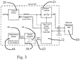
- Figure 3 is a block level electrical schematic of a USB-C connection having over-heating control that receives an analog signal from temperature sensor 44.
- An analog signal 46 is conducted to an analog comparator 48 and compared to the voltage that represents the maximum temperature of reference 50.
- a digital signal 52 transmits the comparison to port controller 12 for a determination if the temperature is within the preset limit.
- the port controller 12 is a Cypress Semiconductor (San Jose, CA) CCG series of USB Type-C controllers.
- Figure 4 is a block level electrical schematic of a USB Type-C connection with one or more temperature sensors 44, Analog to Digital conversion 54, and a logic block 56 to compute desired PDOs.
- Analog signal 46 is converted to a digital signal 52 via analog to digital converter 54 that may be embedded within the port controller 12.
- the temperature sensor could be integrated into a microprocessor such as the Texas Instruments (Dallas, TX) TM4C123GH6PM.
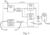
- the schematic in Figure 5 illustrates an implementation where temperature sensor 44 provides a voltage output signal as a digital signal 52 directly to port controller 12 where the signal is compared with a reference and PDO state is changed, if necessary.
- FIG. 6 shows another implementation similar to Figure 5 except there is a separate digital IC processor 58 that receives the temperature sensor 44 data and evaluates the data and sends appropriate commands to the port controller 12.
- any of the above implementations could have multiple temperature sensors with each setting a different PDO or the digital temperature sensor outputs could be OR'ed together to change as little as one bit of the PDO codes. Output of the comparator could be connected to multiple codes as needed to select the appropriate PDO code. A second comparator could be used to set a lower PDO if the first lower PDO still has unacceptable measured temperature.
- an algorithm that models the power supply port uses measured electrical characteristics of the functional components to calculate temperature. Then, a processor running the algorithm then instructs the port controller to negotiate a new source capability:
- USB-C outlet a USB-C outlet
- power sink a power sink
- the power negotiation system described above may be applied to other outlets and other power drawing systems.
- An exemplary 100W capable outlet has 90% constant efficiency.
- the calculated maximum power is 30W at 50°C.
- the outlet would negotiate up to 100W and start delivering power.
- a temperature sensor would monitor internal temperature and an electronic comparator circuit would detect when the sensor output has reached a pre-determined limit.
- the temperature sensor would send a signal to the port controller to renegotiate a lower PDO.
- the PDO would renegotiate to a level that would result in an acceptable internal temperature.
- Figure 7 is a plot of temperature inside and outside a power source port. Temperature sensors were placed in several locations including the air temperature inside the housing of the power source port (Int Ambient) and on components (Q1, D1, T10, UB2, U30) along with the controlled air temperature outside of the power source port (Ambient).
- Figure 7 demonstrates the operation of the invention where the ambient temperature was increased above normal operation conditions and thus increasing the internal temperatures to undesirable levels at the default output power.
- the output power was reduced. The reduction was accomplished with a renegotiation of the source port capabilities and negotiated PDOs.
- the internal temperature was reduced over time as there was less power dissipated.
- the reduced ambient temperature allowed the output power to be increased.
- the increased power is a result of an increased power source port capability and a re-negotiated PDO.
- the internal temperature varies between the minimum threshold and the maximum threshold with the time in between dependent on ambient temperature and the amount of load drawn by the power sink port.
Landscapes
- Engineering & Computer Science (AREA)
- Theoretical Computer Science (AREA)
- General Engineering & Computer Science (AREA)
- Physics & Mathematics (AREA)
- General Physics & Mathematics (AREA)
- Computer Hardware Design (AREA)
- Human Computer Interaction (AREA)
- Power Sources (AREA)
Description
- USB (Universal Serial Bus) Type-C cables, plugs, and receptacles form a standardized electrical interconnection for transmitting electrical power and data. In part, the USB Type-C (USB-C) standard covers a 24 pin fully reversible plug and mating receptacle, referred herein as a USB-C connector. The USB-C standard also covers captive and plug-in cables. USB-C cables are used to connect power sources, such as a power supply in a cabin for an aircraft, to Personal Electronic Devices (PEDs) such as computers, tablets and smart phones.
- The standardized Universal Serial Bus Power Delivery specification (USB PD) includes an ability to negotiate power contracts between a power source and a power sink such as a PED. Power contracts are established when the power source advertises a set of source capabilities, the power sink choses one capability, and then the power source confirms the power sink's choice. The capabilities are defined by data structures called Power Data Objects or Augmented Power Data Objects, referred to herein as PDOs. Under USB PD specifications, PDOs may specify a variety of power source characteristics. Such characteristics include a fixed output, a battery-powered output and programmable outputs. The outputs typically have voltages up to 20V, currents as high as 5A, and resulting power levels up to 100W. By advertising different PDOs, the power source can control the maximum power drawn by a power sink.
- The following definitions are commonly employed with USB PD specifications and are applied herein:
- Power Supply - An electronic device that converts one form of electrical energy to another. As disclosed herein, the power supply converts electrical energy to a USB-C PD specified voltage and current level.
- Port Controller - A device that handles the communication in and out of a source port or sink port and the computing resources allocated to managing the port.
- Source Port - A functional block of circuits that comply with the USB-C and USB PD specifications to provide power. The source port includes a power supply and a port controller
- Sink Port - A functional block of circuits that comply with the USB-C and USB PD specifications that use power provided by a source port.
- All USB source ports dissipate heat, and therefore have internal temperatures and surface temperatures that exceed the ambient temperature. For safety reasons, a typical USB source port will disable the output if an internal temperature reaches a pre-determined limit. While this provides safety protection, it can be an inconvenience to a user of the source port, such as the owner of a PED. Disclosed herein are a system and a method to negotiate the power level of a USB PD capable source port, to keep the internal temperature within safe limits without having to disable the output.
- One example of negotiated power levels is found in United States Patent Application Publication No.
2010/0285828 A1 , titled "Throttling Transmit Power in a WWAN Device Based on Thermal Input," by Panian et al. This publication discloses a wireless wide area network (WWAN) communication system having access terminals located remotely from a base station. A temperature sensor determines an expected increase in temperature in an access terminal based on a target transmit power. A negotiating module then communicates with the base station to set the target transmit power sufficiently low to avoid overheating components of the access terminal. -
WO 2017/044718 A1 (which is not comprised in the state of the art vis-à-vis the appended claims) discloses a power conversion module that provides power delivery capability information to a device powered by the module. The power delivery capability information is determined based on information indicative of the temperature of the power module.US 2013/063098 A1 discloses a system for temperature regulation of a power switch during charging of a portable device. The temperature of the power switch is monitored and compared with a predefined threshold temperature. The charging current may be restricted, based on the comparison.US 2014/325245 A1 discloses a system providing an optimized power delivery and management of the USB power in a closed network, such as found on commercial aircraft. If the total power delivered exceeds a predetermined level then local outputs are shut down. - Disclosed herein is a system to regulate the internal temperature of a power source port. Components of the system include a connector electrically interconnecting the power source port and a power sink port; an output control routing a power supply output to the connector; a port controller having a plurality of source capabilities lists stored thereon in a non-transitory digital medium, each list identifying a different set of power source port capabilities that, based on their power requirements, may be advertised over a power delivery communication channel to the power sink port; one or more temperature sensors measuring the surface temperature of heat dissipating elements or the internal temperature of the power supply and communicating the measured temperature to a comparator.
- One feature of the system is that the comparator compares the measured temperature to predefined limit temperatures. When the measured temperature exceeds a predefined maximum limit temperature, the port controller advertises to the power sink port a source capabilities list with reduced electrical power to reduce internal temperatures. When the measured temperature is below a predefined minimum temperature, the port controller advertises to the power sink port a source capabilities list with increased electrical power. This feature maximizes the electrical power available from the power source port.
- Another feature is that the connector may be a USB Type-C connector.
-
Figure 1 illustrates a system for temperature control in block diagram form. -
Figure 2 illustrates a method to negotiate acceptable PDOs in flow chart designation. -
Figure 3 is a block level electrical schematic of a USB Type-C connection with an Analog temperature compare function. -
Figure 4 is a block level electrical schematic of a USB Type-C connection with one or more temperature sensors, Analog to Digital conversion, and a logic block to compute desired PDOs. -
Figure 5 is a block level electrical schematic of a USB Type-C connection where a sensor voltage output is compared to a reference and the PDO state is changed. -
Figure 6 is an electrical schematic illustrating an implementation with a change to one bit of the PDO codes. -
Figure 7 illustrates a control of internal ambient temperature as a function of time. - The system utilizes a method to control temperature within a power source port by changing the capabilities list and using negotiated PDOs. The system uses one or more thermal measuring devices that compare measured temperatures to one or more limit temperatures, and initiates a re-negotiation of a power contract using a new set of PDOs to adjust the power delivered from a power source to an outlet, thereby controlling the heat dissipated inside the power source and outlet. This allows maximizing the available outlet power while maintaining internal temperatures at acceptable levels. The system utilizes measured temperatures to determine which PDOs can be negotiated by changing the capabilities list of the power source.
- An exemplary USB-C power source port is installed in an aircraft cabin. USB-C power source ports in passenger aircraft cabins are often installed in seatbacks, under the seat, on the seat leg, or in the cabin wall, all locations with a limited capacity to dissipate heat. As the ambient temperature rises, internal power dissipation must be lowered to maintain acceptable internal and surface temperatures. Acceptable internal power dissipation changes with power demand and ambient temperature. In some cases, the internal power dissipation may be safely increased, allowing increased outlet power. Embodiments disclosed herein measure the internal temperature to control the maximum negotiated power. Referencing
Figure 1 , apower source port 1 provides power to apower sink port 10 via a USB-C connector 11, which may be implemented by any combination of receptacles, cables or captive cables allowed by USB-C. Within thepower source port 1 are one ormore temperature sensors 16 that measure the surface temperature of heat dissipating elements or the internal average temperature ofpower supply 20. Thetemperature sensors 16 are typically located in thepower supply 20. In addition to seatbacks in a passenger aircraft, the system disclosed herein is useful for outlets installed in other vehicles, such as seatbacks or cabins for buses, cruise ships and trains. Other venues requiring a large number of outlets, such as auditoriums and theaters also benefit from this system. -
Figure 1 illustrates a system for temperature control in block diagram form. When theswitch 13 inoutput control 21 is closed, power frompower supply 20 is conducted to USB-C connector 11.Power sink port 10 is a USB Type-C and USB PD capable PED. Representative PEDs connected to the USB-C connector 11 include smart phones, computing tablets, laptop computers, USB hubs and other portable electronic equipment. These devices typically require power in the range of from 5W to 100W. As power is delivered to the PED, heat is generated due to inefficiencies in thepower supply 20, theoutput control 21 and the USB-C connectors 11. Thepower sink port 10, such as a PED, is in digital communication with aport controller 12 by way of power negotiation lines 14. Theport controller 12 typically includes, but does not require, a dedicated microprocessor, and this block also represents the portion of any shared hardware or computing resources allocated to managing thepower source port 10.Temperature sensor 16 measures the temperature of thepower source port 1 as influenced by both ambient temperature and the internal power dissipation of the components within thepower source port 1 and transmits the temperature measurements to acomparator 18 that compares the measured temperature to a pre-defined limit. Preferably, onetemperature sensor 16 is positioned to measure the temperature on a surface of the functional element components inside thepower source port 1 predicted to get the hottest. - Typically, for a passenger aircraft, an upper limit ambient temperature for the power source port is 35°C and internal device maximum temperatures are limited by the design margin allowed against material and component manufacturer maximum ratings, generally 85°C to 125°C.
- Exemplary temperature sensors include thermistors, thermocouples, resistance thermometers and silicon bandgaps. The output from these sensors may be analog or digital.
- The
comparator 18 then transmits the temperature information to theport controller 12. A PDO driver circuit, having source capabilities lists stored therein in a non-transient digital memory, is implemented within either thecomparator 18 orport controller 12. - An exemplary source capabilities list would contain:
- 5 Volts at 3 Amps for a power level of 15 Watts;
- 9 Volts at 3 Amps for a power level of 27 Watts;
- 15 Volts at 3 Amps for a power level of 45 Watts; and
- 20 Volts at 3 Amps for a power level of 60 Watts.
- The PDO driver circuit then instructs the
port controller 12 that based on its source capabilities list, which PDOs can be negotiated, via thenegotiation lines 14, and connected to thepower sink port 10 via the USB-C connectors 11. - The
power supply 20 provides power to USB-C connectors 11 when theoutput control 21switch 13 is closed. Theoutput control 21switch 13 is opened or closed by theport controller 12 based on the USB Type C specification and can be opened for safety situations such as over current or excessive temperature. -
Figure 2 illustrates a method to negotiate acceptable PDOs in flow chart designation. At start up, the power source port is initialized 22. During initialization, the upper and lower temperature limits are set, the temperature limit values are communicated to comparators and an initial capability list (PDO) is set. The comparators previously received preset temperature limits determined by the manufacturer during product development to insure acceptable performance. Two temperature limits are specified during initialization, the upper limit is set as the maximum and a lower limit set to give hysteresis and determine when it is acceptable to increase the output power with an expanded set of PDOs. - A temperature sensor measures 25 the temperature of the power source port. A
comparison 23 is made to determine if the measured 25 temperature exceeds the upper temperature limit. If the measured 25 temperature is greater than the upper limit, then the temperature is too high and corrective action to reduce the temperature is commenced. To reduce the temperature, a new capabilities list of PDOs is determined 26 and the new capabilities list of PDOs is set 28 as the PDO in the port controller. If the new capabilities list of PDOs is equivalent to the prior set ofPDOs 27, no change is needed to the PDO capabilities list and the temperature is again measured 25. - If the measured 25 temperature is not greater than the upper limit, the temperature is compared 24 against the lower limit. If the measured 25 temperature exceeds the lower limit temperature, then no change is needed to the PDO and the temperature is measured 25 again. If the measured 25 temperature is less than the lower limit, than the power can be increased and a new capabilities list of PDOs is determined 26. If the new capabilities list of PDOs is not equal to the prior set of
PDOs 27, the new capabilities list of PDOs becomes the set list ofPDOs 28 and a new power contract is negotiated 29, 30 with the power sink port. -
Figure 3 is a block level electrical schematic of a USB-C connection having over-heating control that receives an analog signal fromtemperature sensor 44. There may be multiple temperature sensors required when there are more than one area of thermal concern such as integrated circuits (ICs), switching magnetics and areas with human contact potential. Ananalog signal 46 is conducted to ananalog comparator 48 and compared to the voltage that represents the maximum temperature ofreference 50. Adigital signal 52 transmits the comparison toport controller 12 for a determination if the temperature is within the preset limit. In one embodiment, theport controller 12 is a Cypress Semiconductor (San Jose, CA) CCG series of USB Type-C controllers. -
Figure 4 is a block level electrical schematic of a USB Type-C connection with one ormore temperature sensors 44, Analog toDigital conversion 54, and a logic block 56 to compute desired PDOs.Analog signal 46 is converted to adigital signal 52 via analog todigital converter 54 that may be embedded within theport controller 12. In one embodiment the temperature sensor could be integrated into a microprocessor such as the Texas Instruments (Dallas, TX) TM4C123GH6PM. - The schematic in
Figure 5 illustrates an implementation wheretemperature sensor 44 provides a voltage output signal as adigital signal 52 directly toport controller 12 where the signal is compared with a reference and PDO state is changed, if necessary. - The schematic in
Figure 6 shows another implementation similar toFigure 5 except there is a separate digital IC processor 58 that receives thetemperature sensor 44 data and evaluates the data and sends appropriate commands to theport controller 12. - Any of the above implementations could have multiple temperature sensors with each setting a different PDO or the digital temperature sensor outputs could be OR'ed together to change as little as one bit of the PDO codes. Output of the comparator could be connected to multiple codes as needed to select the appropriate PDO code. A second comparator could be used to set a lower PDO if the first lower PDO still has unacceptable measured temperature.
- Alternatively, but not within the scope of the invention, defined in
claim 1, rather than using temperature sensors, an algorithm that models the power supply port uses measured electrical characteristics of the functional components to calculate temperature. Then, a processor running the algorithm then instructs the port controller to negotiate a new source capability: - Representative software code incorporating such an algorithm is:
PowerUp_Initialize() // Initialization includes set up for thermal calculations
            //Establish initial "Told" value representing the source
            // internal temp rise for nominal internal power dissipation.
            while ... //Main loop with periodic execution
     GetOutputCurrent(...)//Measure output current
     CalcPowerDiss(...) //Calculate source internal power dissipation using:
            // -Measured output current
            // -Known PDO output voltage
            // -Measured input voltage (optional)
            // -Possible table of efficiency adjustment factors
     CalcTempRise(...) //Use difference equation to calculate estimated temp:
            // Tnew = Pwr*Theta/(B+1) + Told*B/(B+1) where
            // "Tnew", "Told" are temperature differences from inside
            // the source to an assumed external ambient temperature.
            // "Pwr" is the calculated/estimated internal power.
            // "Theta" is the effective steady state thermal impedance
            // from inside to outside the source enclosure.
            // "B" is the ratio of the product of the source Theta and
            // thermal capacity to the period of the main calculation loop.
     If Tnew > Tupper then LowerPDO(...) //If calculated Tnew exceeds preset
     upper
                          // temp limit, then execute routine to
                          // negotiate lower power available to sink.
                          // LowerPDO(...) checks against existing
                          // PDO, to avoid unnecessary power
                          //....renegotiation.
     If Tnew < Tlower then RaisePDO(...) //If calculated Tnew drops below
     preset
                         // lower temp limit, then execute routine to
                         // negotiate higher power available to sink.
                         // RaisePDO(...) checks against existing
                         // PDO, to avoid unnecessary power
                         //....renegotiation.
     end while //End of main loop
Claims (6)
- A system to regulate the internal temperature of a power source port (1), comprising:a connector (11) electrically interconnecting the power source port (1) and a power sink port (10);an output control (21) routing a power supply (20) output to the connector (11);a port controller (12) having a plurality of source capabilities lists stored thereon in a non-transitory digital medium, each list identifying a different set of power source port capabilities that, based on their power requirements, may be advertised over a power delivery communication channel (14) to the power sink port (10);one or more temperature sensors (16) measuring the surface temperature of heat dissipating elements or the internal temperature of the power supply (20) and communicating the measured temperature to a comparator (18); andthe comparator (18) comparing the measured temperature to predefined limit temperatures, wherein when the measured temperature exceeds a predefined maximum limit temperature, the port controller (12) advertises to the power sink port (10) a source capabilities list with reduced electrical power to reduce internal temperatures and when the measured temperature is below a predefined minimum temperature, the port controller (12) advertises to the power sink port (10) a source capabilities list with increased electrical power thereby maximizing the electrical power available from the power source port (1).
- The system of claim 1 characterized in that the connector (11) is a USB-C connector.
- The system of claim 2 characterized in that the one or more temperatures sensor(s) (16) measure(s) ambient temperature within the power source port (1).
- The system of claim 2 characterized in that there are multiple temperature sensors (16) disposed about the power source port (1) with one of the temperature sensors (16) measuring a temperature on a surface of a predicted hottest component of a functional element of the power source port.
- The system of claim 2 characterized in that the temperature sensor (16) is an electrical temperature sensor having an analog output selected from the group consisting of thermistor, thermocouple, resistance thermometer and silicon bandgap.
- The system of claim 2 characterized in that the temperature sensor (16) is an electrical temperature sensor having a digital output selected from the group consisting of thermistor, thermocouple, resistance thermometer and silicon bandgap.
Applications Claiming Priority (2)
| Application Number | Priority Date | Filing Date | Title |
|---|---|---|---|
| US201762459679P | 2017-02-16 | 2017-02-16 | |
| US15/863,230 US10534412B2 (en) | 2017-02-16 | 2018-01-05 | Control of temperature in a USB type C source through re-negotiation of power delivery object |
Publications (2)
| Publication Number | Publication Date |
|---|---|
| EP3364267A1 EP3364267A1 (en) | 2018-08-22 |
| EP3364267B1 true EP3364267B1 (en) | 2020-09-30 |
Family
ID=61226473
Family Applications (1)
| Application Number | Title | Priority Date | Filing Date |
|---|---|---|---|
| EP18156927.8A Active EP3364267B1 (en) | 2017-02-16 | 2018-02-15 | Control of temperature in a usb type c source through re-negotiation of power delivery object |
Country Status (2)
| Country | Link |
|---|---|
| US (1) | US10534412B2 (en) |
| EP (1) | EP3364267B1 (en) |
Families Citing this family (28)
| Publication number | Priority date | Publication date | Assignee | Title |
|---|---|---|---|---|
| US20180239410A1 (en) * | 2017-02-17 | 2018-08-23 | Qualcomm Incorporated | Universal serial bus power delivery (usb pd)-based battery charging |
| US20180254644A1 (en) * | 2017-03-06 | 2018-09-06 | Intel Corporation | Techniques for charger control |
| US10895899B2 (en) * | 2017-05-22 | 2021-01-19 | Texas Instruments Incorporated | Regulation circuit to facilitate USB cable compliance |
| CA3059984C (en) | 2017-05-30 | 2024-01-30 | Magic Leap, Inc. | Power supply assembly with fan assembly for electronic device |
| US11398740B2 (en) * | 2018-04-06 | 2022-07-26 | Stmicroelectronics (Grenoble 2) Sas | Method for selecting a supply source power |
| US11152807B2 (en) * | 2018-04-06 | 2021-10-19 | Stmicroelectronics (Grenoble 2) Sas | Method for selecting a supply source power |
| US12099386B2 (en) * | 2018-07-24 | 2024-09-24 | Magic Leap, Inc. | Thermal management system for electronic device |
| US10923941B2 (en) * | 2018-09-18 | 2021-02-16 | Leviton Manufacturing Company, Inc. | Systems and methods for universal serial bus (USB) power delivery with multiple charging ports |
| US12119701B2 (en) * | 2018-09-18 | 2024-10-15 | Leviton Manufacturing Co., Inc. | Systems and methods for universal serial bus (USB) power delivery with multiple charging ports |
| CN109992551B (en) * | 2019-04-09 | 2021-10-26 | 上海闻泰信息技术有限公司 | USB C-type interface information reading method and information reading circuit |
| US11287865B2 (en) * | 2019-06-14 | 2022-03-29 | Microchip Technology Incorporated | USB hub with integrated power and thermal management |
| US11314307B2 (en) * | 2019-09-26 | 2022-04-26 | Data Device Corporation | Smart universal serial bus (USB-PD (power delivery)) outlets for use in aircraft and system and process for implementing the same |
| US11119548B2 (en) * | 2020-01-08 | 2021-09-14 | Cypress Semiconductor Corporation | Dynamic power throttling based on system conditions in USB Type-C power delivery (USB-C/PD) ecosystem |
| GB2592598B8 (en) * | 2020-03-02 | 2024-06-12 | Zahnradfabrik Friedrichshafen | Electric power steering system |
| US11604501B2 (en) * | 2020-10-09 | 2023-03-14 | Siliconch Systems Pvt Ltd | Method and system for temperature-aware power redistribution in a multi-port power sourcing device |
| CN112531839A (en) * | 2020-12-02 | 2021-03-19 | 深圳慧能泰半导体科技有限公司 | USB cable control device with temperature limitation and method |
| US11442519B1 (en) * | 2021-02-23 | 2022-09-13 | Dell Products L.P. | External power supply and method to enhance the output power delivered by an external power supply |
| JP2022180826A (en) * | 2021-05-25 | 2022-12-07 | キヤノン株式会社 | Control device, control method and program for control device |
| US11927998B2 (en) * | 2021-06-08 | 2024-03-12 | Dell Products L.P. | System performance using optimal adapter efficiency |
| EP4125175A1 (en) * | 2021-07-29 | 2023-02-01 | KID-Systeme GmbH | Electric power distribution system and method for determining a profile of temperature dependent on power provided to electrical consumers |
| CN114416624A (en) * | 2022-01-05 | 2022-04-29 | 昂宝电子(上海)有限公司 | USB interface and control circuit and control method thereof |
| US20220215147A1 (en) * | 2022-03-24 | 2022-07-07 | Intel Corporation | Temperature Control Systems And Methods For Integrated Circuits |
| US20230333527A1 (en) * | 2022-04-13 | 2023-10-19 | Dell Products L.P. | Enhanced capacity management of power supplies in response to environmental conditions |
| WO2024029417A1 (en) * | 2022-08-05 | 2024-02-08 | パナソニックホールディングス株式会社 | Usb power feed device and method for controlling same |
| US12498780B2 (en) * | 2023-01-30 | 2025-12-16 | Hewlett Packard Enterprise Development Lp | Dynamic pluggable module power management |
| CN119718171A (en) * | 2023-09-27 | 2025-03-28 | 长江存储科技有限责任公司 | Memory system and operation method thereof, and computer readable storage medium |
| DE102023136073B4 (en) * | 2023-12-20 | 2025-08-07 | Bury Sp. Z. O. O. | Electrical supply device and method for the electrical supply of accumulators with a supply interface according to the USB standard |
| TWI898663B (en) * | 2024-06-17 | 2025-09-21 | 宏碁股份有限公司 | Link state control method and data storage system |
Family Cites Families (10)
| Publication number | Priority date | Publication date | Assignee | Title |
|---|---|---|---|---|
| US7421623B2 (en) | 2004-07-08 | 2008-09-02 | International Business Machines Corporation | Systems, methods, and media for controlling temperature in a computer system |
| US8244296B2 (en) | 2008-10-15 | 2012-08-14 | Apple Inc. | Dynamic thermal control for wireless transceivers |
| US8229492B2 (en) | 2009-05-08 | 2012-07-24 | Qualcomm Incorporated | Throttling transmit power in a WWAN device based upon thermal input |
| US8884589B2 (en) * | 2011-09-14 | 2014-11-11 | Standard Microsystems Corporation | Method and system for power switch temperature regulation |
| US20140268563A1 (en) * | 2013-03-15 | 2014-09-18 | Finsix Corporation | Method and apparatus for controlling heat in power conversion systems |
| US20140325245A1 (en) | 2013-04-29 | 2014-10-30 | Transistor Devices, Inc. D/B/A Tdi Power | USB Power Distribution Management System |
| US9774186B2 (en) * | 2014-03-31 | 2017-09-26 | Google Technology Holdings LLC | Power supply system with multiple output ports and associated methods for output port power management |
| WO2017044718A1 (en) | 2015-09-09 | 2017-03-16 | Finsix Corporation | Control of power delivery based on temperature of a power module |
| TWI639922B (en) * | 2016-09-08 | 2018-11-01 | Eever Technology, Inc. | Usb type-c connecting module |
| US10817457B2 (en) * | 2016-11-23 | 2020-10-27 | Fairchild Semiconductor Corporation | Self identification and pollution detection in USB Type-C |
-
2018
- 2018-01-05 US US15/863,230 patent/US10534412B2/en active Active
- 2018-02-15 EP EP18156927.8A patent/EP3364267B1/en active Active
Non-Patent Citations (1)
| Title |
|---|
| None * |
Also Published As
| Publication number | Publication date |
|---|---|
| US20180232021A1 (en) | 2018-08-16 |
| EP3364267A1 (en) | 2018-08-22 |
| US10534412B2 (en) | 2020-01-14 |
Similar Documents
| Publication | Publication Date | Title |
|---|---|---|
| US10534412B2 (en) | Control of temperature in a USB type C source through re-negotiation of power delivery object | |
| CN108462167B (en) | USB power management and load distribution system | |
| US20250007315A1 (en) | Systems and methods for universal serial bus (usb) power delivery with multiple charging ports | |
| US12119701B2 (en) | Systems and methods for universal serial bus (USB) power delivery with multiple charging ports | |
| CN105960619B (en) | Circuit and method for controlling skin temperature of an electronic device | |
| US10175748B2 (en) | System, method and computer program product for improved regulation of an electrical device's consumption of power from an external power supply | |
| EP3178145B1 (en) | Power distribution system | |
| EP3043442B1 (en) | Hub having complex power converters | |
| CN100544173C (en) | Power control method and circuit, and power supply device | |
| JP5763455B2 (en) | Host apparatus, device and communication system | |
| KR20180072834A (en) | Power charging module and method of using same | |
| WO1998050994A1 (en) | A circuit and method for controlling power and performance based on operating environment | |
| US20180097385A1 (en) | Hub | |
| WO2003050667A2 (en) | System for shared power supply in computer peripheral devices | |
| CN105793798A (en) | Serial bus voltage compensation | |
| JP5288446B2 (en) | Electronic device system and power control method thereof | |
| US11442519B1 (en) | External power supply and method to enhance the output power delivered by an external power supply | |
| CN107040045A (en) | Systems and methods for securing wireless power transfer systems | |
| JP7705967B2 (en) | Electrical power supply cable for a vehicle | |
| CA3157559C (en) | Charging apparatus and charging method | |
| CN107658645B (en) | Power plug device and over-temperature protection method thereof | |
| CN109995225B (en) | Power supply with adjustable power consumption limit and method for adjusting power consumption limit | |
| CN110495085A (en) | DC-DC converter with bullet terminals | |
| US20170070064A1 (en) | Electronic device, method for controlling electronic device and program for controlling electronic device | |
| CN214590712U (en) | Charging device |
Legal Events
| Date | Code | Title | Description |
|---|---|---|---|
| PUAI | Public reference made under article 153(3) epc to a published international application that has entered the european phase |
Free format text: ORIGINAL CODE: 0009012 |
|
| STAA | Information on the status of an ep patent application or granted ep patent |
Free format text: STATUS: THE APPLICATION HAS BEEN PUBLISHED |
|
| STAA | Information on the status of an ep patent application or granted ep patent |
Free format text: STATUS: REQUEST FOR EXAMINATION WAS MADE |
|
| AK | Designated contracting states |
Kind code of ref document: A1 Designated state(s): AL AT BE BG CH CY CZ DE DK EE ES FI FR GB GR HR HU IE IS IT LI LT LU LV MC MK MT NL NO PL PT RO RS SE SI SK SM TR |
|
| AX | Request for extension of the european patent |
Extension state: BA ME |
|
| 17P | Request for examination filed |
Effective date: 20180810 |
|
| RBV | Designated contracting states (corrected) |
Designated state(s): AL AT BE BG CH CY CZ DE DK EE ES FI FR GB GR HR HU IE IS IT LI LT LU LV MC MK MT NL NO PL PT RO RS SE SI SK SM TR |
|
| GRAP | Despatch of communication of intention to grant a patent |
Free format text: ORIGINAL CODE: EPIDOSNIGR1 |
|
| STAA | Information on the status of an ep patent application or granted ep patent |
Free format text: STATUS: GRANT OF PATENT IS INTENDED |
|
| RIC1 | Information provided on ipc code assigned before grant |
Ipc: G06F 1/3206 20190101ALI20200525BHEP Ipc: G06F 1/3234 20190101ALI20200525BHEP Ipc: G06F 1/3215 20190101ALI20200525BHEP Ipc: G06F 1/26 20060101ALI20200525BHEP Ipc: G06F 1/20 20060101AFI20200525BHEP Ipc: G06F 13/38 20060101ALI20200525BHEP |
|
| INTG | Intention to grant announced |
Effective date: 20200626 |
|
| GRAS | Grant fee paid |
Free format text: ORIGINAL CODE: EPIDOSNIGR3 |
|
| GRAA | (expected) grant |
Free format text: ORIGINAL CODE: 0009210 |
|
| STAA | Information on the status of an ep patent application or granted ep patent |
Free format text: STATUS: THE PATENT HAS BEEN GRANTED |
|
| AK | Designated contracting states |
Kind code of ref document: B1 Designated state(s): AL AT BE BG CH CY CZ DE DK EE ES FI FR GB GR HR HU IE IS IT LI LT LU LV MC MK MT NL NO PL PT RO RS SE SI SK SM TR |
|
| REG | Reference to a national code |
Ref country code: GB Ref legal event code: FG4D Ref country code: CH Ref legal event code: EP |
|
| REG | Reference to a national code |
Ref country code: AT Ref legal event code: REF Ref document number: 1319471 Country of ref document: AT Kind code of ref document: T Effective date: 20201015 |
|
| REG | Reference to a national code |
Ref country code: DE Ref legal event code: R096 Ref document number: 602018008162 Country of ref document: DE |
|
| REG | Reference to a national code |
Ref country code: IE Ref legal event code: FG4D |
|
| PG25 | Lapsed in a contracting state [announced via postgrant information from national office to epo] |
Ref country code: NO Free format text: LAPSE BECAUSE OF FAILURE TO SUBMIT A TRANSLATION OF THE DESCRIPTION OR TO PAY THE FEE WITHIN THE PRESCRIBED TIME-LIMIT Effective date: 20201230 Ref country code: GR Free format text: LAPSE BECAUSE OF FAILURE TO SUBMIT A TRANSLATION OF THE DESCRIPTION OR TO PAY THE FEE WITHIN THE PRESCRIBED TIME-LIMIT Effective date: 20201231 Ref country code: FI Free format text: LAPSE BECAUSE OF FAILURE TO SUBMIT A TRANSLATION OF THE DESCRIPTION OR TO PAY THE FEE WITHIN THE PRESCRIBED TIME-LIMIT Effective date: 20200930 Ref country code: HR Free format text: LAPSE BECAUSE OF FAILURE TO SUBMIT A TRANSLATION OF THE DESCRIPTION OR TO PAY THE FEE WITHIN THE PRESCRIBED TIME-LIMIT Effective date: 20200930 Ref country code: BG Free format text: LAPSE BECAUSE OF FAILURE TO SUBMIT A TRANSLATION OF THE DESCRIPTION OR TO PAY THE FEE WITHIN THE PRESCRIBED TIME-LIMIT Effective date: 20201230 Ref country code: SE Free format text: LAPSE BECAUSE OF FAILURE TO SUBMIT A TRANSLATION OF THE DESCRIPTION OR TO PAY THE FEE WITHIN THE PRESCRIBED TIME-LIMIT Effective date: 20200930 |
|
| REG | Reference to a national code |
Ref country code: AT Ref legal event code: MK05 Ref document number: 1319471 Country of ref document: AT Kind code of ref document: T Effective date: 20200930 |
|
| PG25 | Lapsed in a contracting state [announced via postgrant information from national office to epo] |
Ref country code: RS Free format text: LAPSE BECAUSE OF FAILURE TO SUBMIT A TRANSLATION OF THE DESCRIPTION OR TO PAY THE FEE WITHIN THE PRESCRIBED TIME-LIMIT Effective date: 20200930 Ref country code: LV Free format text: LAPSE BECAUSE OF FAILURE TO SUBMIT A TRANSLATION OF THE DESCRIPTION OR TO PAY THE FEE WITHIN THE PRESCRIBED TIME-LIMIT Effective date: 20200930 |
|
| REG | Reference to a national code |
Ref country code: NL Ref legal event code: MP Effective date: 20200930 |
|
| REG | Reference to a national code |
Ref country code: LT Ref legal event code: MG4D |
|
| PG25 | Lapsed in a contracting state [announced via postgrant information from national office to epo] |
Ref country code: SM Free format text: LAPSE BECAUSE OF FAILURE TO SUBMIT A TRANSLATION OF THE DESCRIPTION OR TO PAY THE FEE WITHIN THE PRESCRIBED TIME-LIMIT Effective date: 20200930 Ref country code: LT Free format text: LAPSE BECAUSE OF FAILURE TO SUBMIT A TRANSLATION OF THE DESCRIPTION OR TO PAY THE FEE WITHIN THE PRESCRIBED TIME-LIMIT Effective date: 20200930 Ref country code: CZ Free format text: LAPSE BECAUSE OF FAILURE TO SUBMIT A TRANSLATION OF THE DESCRIPTION OR TO PAY THE FEE WITHIN THE PRESCRIBED TIME-LIMIT Effective date: 20200930 Ref country code: RO Free format text: LAPSE BECAUSE OF FAILURE TO SUBMIT A TRANSLATION OF THE DESCRIPTION OR TO PAY THE FEE WITHIN THE PRESCRIBED TIME-LIMIT Effective date: 20200930 Ref country code: PT Free format text: LAPSE BECAUSE OF FAILURE TO SUBMIT A TRANSLATION OF THE DESCRIPTION OR TO PAY THE FEE WITHIN THE PRESCRIBED TIME-LIMIT Effective date: 20210201 Ref country code: EE Free format text: LAPSE BECAUSE OF FAILURE TO SUBMIT A TRANSLATION OF THE DESCRIPTION OR TO PAY THE FEE WITHIN THE PRESCRIBED TIME-LIMIT Effective date: 20200930 |
|
| PG25 | Lapsed in a contracting state [announced via postgrant information from national office to epo] |
Ref country code: AL Free format text: LAPSE BECAUSE OF FAILURE TO SUBMIT A TRANSLATION OF THE DESCRIPTION OR TO PAY THE FEE WITHIN THE PRESCRIBED TIME-LIMIT Effective date: 20200930 Ref country code: AT Free format text: LAPSE BECAUSE OF FAILURE TO SUBMIT A TRANSLATION OF THE DESCRIPTION OR TO PAY THE FEE WITHIN THE PRESCRIBED TIME-LIMIT Effective date: 20200930 Ref country code: ES Free format text: LAPSE BECAUSE OF FAILURE TO SUBMIT A TRANSLATION OF THE DESCRIPTION OR TO PAY THE FEE WITHIN THE PRESCRIBED TIME-LIMIT Effective date: 20200930 Ref country code: IS Free format text: LAPSE BECAUSE OF FAILURE TO SUBMIT A TRANSLATION OF THE DESCRIPTION OR TO PAY THE FEE WITHIN THE PRESCRIBED TIME-LIMIT Effective date: 20210130 Ref country code: PL Free format text: LAPSE BECAUSE OF FAILURE TO SUBMIT A TRANSLATION OF THE DESCRIPTION OR TO PAY THE FEE WITHIN THE PRESCRIBED TIME-LIMIT Effective date: 20200930 |
|
| PG25 | Lapsed in a contracting state [announced via postgrant information from national office to epo] |
Ref country code: SK Free format text: LAPSE BECAUSE OF FAILURE TO SUBMIT A TRANSLATION OF THE DESCRIPTION OR TO PAY THE FEE WITHIN THE PRESCRIBED TIME-LIMIT Effective date: 20200930 Ref country code: NL Free format text: LAPSE BECAUSE OF FAILURE TO SUBMIT A TRANSLATION OF THE DESCRIPTION OR TO PAY THE FEE WITHIN THE PRESCRIBED TIME-LIMIT Effective date: 20200930 |
|
| REG | Reference to a national code |
Ref country code: DE Ref legal event code: R097 Ref document number: 602018008162 Country of ref document: DE |
|
| PLBE | No opposition filed within time limit |
Free format text: ORIGINAL CODE: 0009261 |
|
| STAA | Information on the status of an ep patent application or granted ep patent |
Free format text: STATUS: NO OPPOSITION FILED WITHIN TIME LIMIT |
|
| PG25 | Lapsed in a contracting state [announced via postgrant information from national office to epo] |
Ref country code: DK Free format text: LAPSE BECAUSE OF FAILURE TO SUBMIT A TRANSLATION OF THE DESCRIPTION OR TO PAY THE FEE WITHIN THE PRESCRIBED TIME-LIMIT Effective date: 20200930 |
|
| 26N | No opposition filed |
Effective date: 20210701 |
|
| PG25 | Lapsed in a contracting state [announced via postgrant information from national office to epo] |
Ref country code: MC Free format text: LAPSE BECAUSE OF FAILURE TO SUBMIT A TRANSLATION OF THE DESCRIPTION OR TO PAY THE FEE WITHIN THE PRESCRIBED TIME-LIMIT Effective date: 20200930 |
|
| REG | Reference to a national code |
Ref country code: BE Ref legal event code: MM Effective date: 20210228 |
|
| PG25 | Lapsed in a contracting state [announced via postgrant information from national office to epo] |
Ref country code: IT Free format text: LAPSE BECAUSE OF FAILURE TO SUBMIT A TRANSLATION OF THE DESCRIPTION OR TO PAY THE FEE WITHIN THE PRESCRIBED TIME-LIMIT Effective date: 20200930 Ref country code: LU Free format text: LAPSE BECAUSE OF NON-PAYMENT OF DUE FEES Effective date: 20210215 Ref country code: LI Free format text: LAPSE BECAUSE OF NON-PAYMENT OF DUE FEES Effective date: 20210228 Ref country code: CH Free format text: LAPSE BECAUSE OF NON-PAYMENT OF DUE FEES Effective date: 20210228 |
|
| PG25 | Lapsed in a contracting state [announced via postgrant information from national office to epo] |
Ref country code: SI Free format text: LAPSE BECAUSE OF FAILURE TO SUBMIT A TRANSLATION OF THE DESCRIPTION OR TO PAY THE FEE WITHIN THE PRESCRIBED TIME-LIMIT Effective date: 20200930 |
|
| PG25 | Lapsed in a contracting state [announced via postgrant information from national office to epo] |
Ref country code: IE Free format text: LAPSE BECAUSE OF NON-PAYMENT OF DUE FEES Effective date: 20210215 |
|
| PG25 | Lapsed in a contracting state [announced via postgrant information from national office to epo] |
Ref country code: IS Free format text: LAPSE BECAUSE OF FAILURE TO SUBMIT A TRANSLATION OF THE DESCRIPTION OR TO PAY THE FEE WITHIN THE PRESCRIBED TIME-LIMIT Effective date: 20210130 |
|
| PG25 | Lapsed in a contracting state [announced via postgrant information from national office to epo] |
Ref country code: BE Free format text: LAPSE BECAUSE OF NON-PAYMENT OF DUE FEES Effective date: 20210228 |
|
| PG25 | Lapsed in a contracting state [announced via postgrant information from national office to epo] |
Ref country code: CY Free format text: LAPSE BECAUSE OF FAILURE TO SUBMIT A TRANSLATION OF THE DESCRIPTION OR TO PAY THE FEE WITHIN THE PRESCRIBED TIME-LIMIT Effective date: 20200930 |
|
| PG25 | Lapsed in a contracting state [announced via postgrant information from national office to epo] |
Ref country code: HU Free format text: LAPSE BECAUSE OF FAILURE TO SUBMIT A TRANSLATION OF THE DESCRIPTION OR TO PAY THE FEE WITHIN THE PRESCRIBED TIME-LIMIT; INVALID AB INITIO Effective date: 20180215 |
|
| PG25 | Lapsed in a contracting state [announced via postgrant information from national office to epo] |
Ref country code: MK Free format text: LAPSE BECAUSE OF FAILURE TO SUBMIT A TRANSLATION OF THE DESCRIPTION OR TO PAY THE FEE WITHIN THE PRESCRIBED TIME-LIMIT Effective date: 20200930 |
|
| PG25 | Lapsed in a contracting state [announced via postgrant information from national office to epo] |
Ref country code: MT Free format text: LAPSE BECAUSE OF FAILURE TO SUBMIT A TRANSLATION OF THE DESCRIPTION OR TO PAY THE FEE WITHIN THE PRESCRIBED TIME-LIMIT Effective date: 20200930 |
|
| PG25 | Lapsed in a contracting state [announced via postgrant information from national office to epo] |
Ref country code: TR Free format text: LAPSE BECAUSE OF FAILURE TO SUBMIT A TRANSLATION OF THE DESCRIPTION OR TO PAY THE FEE WITHIN THE PRESCRIBED TIME-LIMIT Effective date: 20200930 |
|
| PGFP | Annual fee paid to national office [announced via postgrant information from national office to epo] |
Ref country code: GB Payment date: 20260227 Year of fee payment: 9 |
|
| PGFP | Annual fee paid to national office [announced via postgrant information from national office to epo] |
Ref country code: DE Payment date: 20260227 Year of fee payment: 9 |
|
| PGFP | Annual fee paid to national office [announced via postgrant information from national office to epo] |
Ref country code: FR Payment date: 20260225 Year of fee payment: 9 |