EP3364212A1 - A method and an apparatus for computer-assisted processing of sar raw data - Google Patents
A method and an apparatus for computer-assisted processing of sar raw data Download PDFInfo
- Publication number
- EP3364212A1 EP3364212A1 EP17156196.2A EP17156196A EP3364212A1 EP 3364212 A1 EP3364212 A1 EP 3364212A1 EP 17156196 A EP17156196 A EP 17156196A EP 3364212 A1 EP3364212 A1 EP 3364212A1
- Authority
- EP
- European Patent Office
- Prior art keywords
- radar
- calibration
- channel
- reference target
- target
- Prior art date
- Legal status (The legal status is an assumption and is not a legal conclusion. Google has not performed a legal analysis and makes no representation as to the accuracy of the status listed.)
- Granted
Links
Images

Classifications
-
- G—PHYSICS
- G01—MEASURING; TESTING
- G01S—RADIO DIRECTION-FINDING; RADIO NAVIGATION; DETERMINING DISTANCE OR VELOCITY BY USE OF RADIO WAVES; LOCATING OR PRESENCE-DETECTING BY USE OF THE REFLECTION OR RERADIATION OF RADIO WAVES; ANALOGOUS ARRANGEMENTS USING OTHER WAVES
- G01S13/00—Systems using the reflection or reradiation of radio waves, e.g. radar systems; Analogous systems using reflection or reradiation of waves whose nature or wavelength is irrelevant or unspecified
- G01S13/88—Radar or analogous systems specially adapted for specific applications
- G01S13/89—Radar or analogous systems specially adapted for specific applications for mapping or imaging
- G01S13/90—Radar or analogous systems specially adapted for specific applications for mapping or imaging using synthetic aperture techniques, e.g. synthetic aperture radar [SAR] techniques
-
- G—PHYSICS
- G01—MEASURING; TESTING
- G01S—RADIO DIRECTION-FINDING; RADIO NAVIGATION; DETERMINING DISTANCE OR VELOCITY BY USE OF RADIO WAVES; LOCATING OR PRESENCE-DETECTING BY USE OF THE REFLECTION OR RERADIATION OF RADIO WAVES; ANALOGOUS ARRANGEMENTS USING OTHER WAVES
- G01S13/00—Systems using the reflection or reradiation of radio waves, e.g. radar systems; Analogous systems using reflection or reradiation of waves whose nature or wavelength is irrelevant or unspecified
- G01S13/88—Radar or analogous systems specially adapted for specific applications
- G01S13/89—Radar or analogous systems specially adapted for specific applications for mapping or imaging
- G01S13/90—Radar or analogous systems specially adapted for specific applications for mapping or imaging using synthetic aperture techniques, e.g. synthetic aperture radar [SAR] techniques
- G01S13/9021—SAR image post-processing techniques
- G01S13/9023—SAR image post-processing techniques combined with interferometric techniques
-
- G—PHYSICS
- G01—MEASURING; TESTING
- G01S—RADIO DIRECTION-FINDING; RADIO NAVIGATION; DETERMINING DISTANCE OR VELOCITY BY USE OF RADIO WAVES; LOCATING OR PRESENCE-DETECTING BY USE OF THE REFLECTION OR RERADIATION OF RADIO WAVES; ANALOGOUS ARRANGEMENTS USING OTHER WAVES
- G01S7/00—Details of systems according to groups G01S13/00, G01S15/00, G01S17/00
- G01S7/02—Details of systems according to groups G01S13/00, G01S15/00, G01S17/00 of systems according to group G01S13/00
- G01S7/40—Means for monitoring or calibrating
- G01S7/4004—Means for monitoring or calibrating of parts of a radar system
- G01S7/4021—Means for monitoring or calibrating of parts of a radar system of receivers
-
- G—PHYSICS
- G01—MEASURING; TESTING
- G01S—RADIO DIRECTION-FINDING; RADIO NAVIGATION; DETERMINING DISTANCE OR VELOCITY BY USE OF RADIO WAVES; LOCATING OR PRESENCE-DETECTING BY USE OF THE REFLECTION OR RERADIATION OF RADIO WAVES; ANALOGOUS ARRANGEMENTS USING OTHER WAVES
- G01S7/00—Details of systems according to groups G01S13/00, G01S15/00, G01S17/00
- G01S7/02—Details of systems according to groups G01S13/00, G01S15/00, G01S17/00 of systems according to group G01S13/00
- G01S7/40—Means for monitoring or calibrating
- G01S7/4052—Means for monitoring or calibrating by simulation of echoes
-
- G—PHYSICS
- G01—MEASURING; TESTING
- G01S—RADIO DIRECTION-FINDING; RADIO NAVIGATION; DETERMINING DISTANCE OR VELOCITY BY USE OF RADIO WAVES; LOCATING OR PRESENCE-DETECTING BY USE OF THE REFLECTION OR RERADIATION OF RADIO WAVES; ANALOGOUS ARRANGEMENTS USING OTHER WAVES
- G01S7/00—Details of systems according to groups G01S13/00, G01S15/00, G01S17/00
- G01S7/02—Details of systems according to groups G01S13/00, G01S15/00, G01S17/00 of systems according to group G01S13/00
- G01S7/40—Means for monitoring or calibrating
- G01S7/4052—Means for monitoring or calibrating by simulation of echoes
- G01S7/4082—Means for monitoring or calibrating by simulation of echoes using externally generated reference signals, e.g. via remote reflector or transponder
- G01S7/4091—Means for monitoring or calibrating by simulation of echoes using externally generated reference signals, e.g. via remote reflector or transponder during normal radar operation
-
- G—PHYSICS
- G01—MEASURING; TESTING
- G01S—RADIO DIRECTION-FINDING; RADIO NAVIGATION; DETERMINING DISTANCE OR VELOCITY BY USE OF RADIO WAVES; LOCATING OR PRESENCE-DETECTING BY USE OF THE REFLECTION OR RERADIATION OF RADIO WAVES; ANALOGOUS ARRANGEMENTS USING OTHER WAVES
- G01S7/00—Details of systems according to groups G01S13/00, G01S15/00, G01S17/00
- G01S7/02—Details of systems according to groups G01S13/00, G01S15/00, G01S17/00 of systems according to group G01S13/00
- G01S7/40—Means for monitoring or calibrating
- G01S7/4004—Means for monitoring or calibrating of parts of a radar system
- G01S7/4026—Antenna boresight
- G01S7/403—Antenna boresight in azimuth, i.e. in the horizontal plane
-
- G—PHYSICS
- G01—MEASURING; TESTING
- G01S—RADIO DIRECTION-FINDING; RADIO NAVIGATION; DETERMINING DISTANCE OR VELOCITY BY USE OF RADIO WAVES; LOCATING OR PRESENCE-DETECTING BY USE OF THE REFLECTION OR RERADIATION OF RADIO WAVES; ANALOGOUS ARRANGEMENTS USING OTHER WAVES
- G01S7/00—Details of systems according to groups G01S13/00, G01S15/00, G01S17/00
- G01S7/02—Details of systems according to groups G01S13/00, G01S15/00, G01S17/00 of systems according to group G01S13/00
- G01S7/40—Means for monitoring or calibrating
- G01S7/4004—Means for monitoring or calibrating of parts of a radar system
- G01S7/4026—Antenna boresight
- G01S7/4034—Antenna boresight in elevation, i.e. in the vertical plane
Definitions
- the invention refers to a method and an apparatus for computer-assisted processing of SAR raw data.
- Synthetic aperture radar is a technique for remote sensing that is being used increasingly in imaging, monitoring and investigation on the earth's surface.
- a SAR radar system consists of a flying object, e.g. a satellite or an airplane, which moves at a constant speed, and a radar sensor that points in a direction orthogonal to the direction of motion. The radar sensor periodically transmits electromagnetic waves and records the echoes of those waves reflected on ground.
- SAR raw data acquisitions are followed by a computationally intensive processing step called image formation or SAR focussing in which echoes recorded in the SAR raw data are back-projected onto the ground to yield the actual image of the scene.
- image formation or SAR focussing in which echoes recorded in the SAR raw data are back-projected onto the ground to yield the actual image of the scene.
- this processing must also ensure an accurate sensor calibration that enables users of the data to relate the SAR sensor measurement to physical parameters of interest and geolocate this information.
- SAR sensor calibration consists of an internal calibration and an external calibration.
- the internal calibration is based on measurements performed internally by the SAR sensor itself. These measurements typically use dedicated hardware to regularly monitor the sensor state that can later be used to compensate for temporal variations in the transmitted electromagnetic wave and any signal distortions that occur when echoes from the image scene are received and recorded.
- External SAR sensor calibration is based on the analysis of reference targets with known radar cross sections and positions on ground.
- the reference targets may be active transponders that transmit signals in response to incoming radar pulses or passive reference targets, such as dihedral of trihedral radar reflectors, which reflect transmitted radar pulses back towards the radar sensor.
- the method of the invention provides a computer-assisted processing of SAR raw data, comprising radar echoes from ground (i.e. the earth's surface) that are the response to radar pulses that have been transmitted by antenna elements of a radar sensor on at least one flying object (e.g. a single flying object) moving in an azimuth direction above ground and where the radar echoes have been received by antenna elements of the radar sensor.
- the flying object may refer to an airplane, a satellite or the like.
- the SAR raw data comprise several data channels, each of which includes radar echoes originating from reference targets with known radar cross sections and positions on ground.
- Each channel is identified by the combination of two antenna elements used to transmit pulses and receive echoes, and the data acquisition for a channel comprises a plurality of data samples for several azimuth positions and several range positions, the range positions corresponding to different distances from the radar sensor to ground.
- the method of the invention comprises one or more calibration procedures.
- Each calibration procedure includes steps i) and ii) described in the following.
- Step i) uses the known radar cross section and position on ground for each reference target in order to extract target data for each reference target in each channel from the SAR raw data and in order to determine a variation of one or more measurements over different radar echoes (i.e. radar echoes received in response to different radar pulses) originating from each reference target for each channel or for each combination of two channels based on the target data.
- the term "measurement” is to be interpreted broadly and may refer to any value which can be derived from the target data. The term “measurement” was chosen because the target data are based on SAR raw data which form measured values.
- one or more calibration factors in the form of one or more correction terms for one or more sensor parameters of the radar sensor are determined based on an optimisation comprising the optimisation goal to (simultaneously) minimise the variation of one or more measurements for all reference targets and for all channels or all combinations of two channels.
- the above minimisation can be defined in terms of corresponding error functions, where examples of such error functions are given in the detailed description.
- the measurements defined above refer to a residual phase and/or to a residual delay and/or to the difference between two residual phases for two channels and/or to a radar cross section offset. These quantities are defined as described with respect to embodiments explained later on.
- the one or more sensor parameters preferably refer to antenna mount angles of each antenna element and/or relative positions of the phase centres of the antenna elements with respect to a reference position on the at least one flying object.
- the method of the invention has the advantage that calibration factors can be derived from the SAR raw data without focusing corresponding SAR images. This is especially important in situations where image focusing presupposes precise calibration (e.g. for sensors that employ beamforming).
- the approach provides a systematic way for analysing and correcting propagation direction dependent calibration issues, which is not the case for conventional techniques. Calibration is achieved by an optimisation designed to minimise the variation of measurements for all reference targets and for all channels or all combinations of two channels.
- the invention results in reliable calibration factors that can be used to improve image quality when processing new SAR raw data acquired by the radar sensor over areas that do not include reference targets. To do so, the calibration factors are applied to the respective sensor parameters during SAR image focusing.
- the one or more calibration procedures comprise a first calibration procedure.
- the variation of a measurement determined in step i) refers to the variation of a radar cross section offset over different radar echoes originating from each reference target in each channel.
- correction terms for sensor parameters in the form of antenna mount angles of each antenna element on the at least one flying object are determined in step ii).
- the radar cross section offset represents the difference between the known radar cross section and the radar cross section according to the target data for the respective reference target and the respective channel.
- the one or more calibration procedures comprise a second calibration procedure.
- the variation of a measurement determined in step i) refers to the variation of a residual phase over different radar echoes originating from each reference target in each channel.
- correction terms for sensor parameters in the form of relative positions of the phase centres of the antenna elements with respect to a reference position on the at least one flying object are determined in step ii).
- the residual phase for a respective channel represents the difference between the (expected) phase of a radar echo based on the positions of the transmitting and receiving antenna element phase centres of the respective channel and based on the known position of the respective reference target on ground on the one hand and the phase according to the target data for the respective reference target on the other hand.
- the optimisation within the second calibration procedure includes the additional optimisation goal to minimise the mean residual delay over different radar echoes originating from each reference target in each channel, where the residual delay for a respective channel represents the difference between the (expected) propagation time from transmitting a radar pulse until receiving its radar echo based on the positions of the transmitting and receiving antenna element phase centres of the respective channel and based on the known position of the respective reference target on ground on the one hand and the corresponding propagation time according to the target data for the respective reference target on the other hand.
- positions of the transmitting and receiving antenna element phase centres these positions can be determined with well-known methods during data acquisition, e.g. by using a navigation system of the at least one flying object. These positions initially contain residual errors which may later be compensated by calibration factors.
- the one or more calibration procedures comprise a third calibration procedure.
- the variation of a measurement determined in step i) refers to the variation of the difference between two residual phases for two (different) channels over different radar echoes originating from each reference target in each combination of two (different) channels.
- correction terms for sensor parameters in the form of relative positions of the phase centres of the antenna elements with respect to a reference position on the at least one flying object are determined in step ii).
- the residual phase for a respective channel represents the difference between the phase of a radar echo based on the positions of the transmitting and receiving antenna element phase centres of the respective channel and based on the known position of the respective reference target on ground on the one hand and the phase according to the target data for the respective reference target on the other hand.
- the third calibration procedure is preferably performed as a refinement of the above described second calibration procedure.
- the method can comprise any combination of those calibration procedures or only one of those calibration procedures.
- the method comprises the first and the second and the third calibration procedures, resulting in very accurate calibration factors.
- the third calibration procedure is performed after the second calibration procedure and the second calibration procedure is performed after the first calibration procedure.
- the method according to the invention comprises several calibration procedures which are performed based on an iteration, where each calibration procedure constitutes an iteration step and where step i) of an iteration step (i.e. the associated calibration procedure) takes into account one or more calibration factors determined in all preceding iteration steps.
- step i) of an iteration step i.e. the associated calibration procedure
- the extraction of target data for each reference target and each channel in step i) of at least one calibration procedure comprises a well-known range compression as well as a correction based on the known radar cross section and the known position of the respective reference target on ground.
- the correction is further based on the antenna diagrams of the transmitting and receiving antenna elements associated with the respective channel and/or based on the expected propagation time from the phase centre of the transmit antenna element to the respective reference target and back to the phase centre of the receive antenna element in the respective channel and/or based on internal calibration data acquired by recording pulses that have traversed the same transmit and receive branches in the radar sensor as target data in the respective channel.
- the expected propagation time is determined based on the positions of the transmitting and receiving antenna element phase centres of the respective channel and based on the known position of the respective reference target on ground.
- the extraction of target data for each reference target and each channel in step i) of at least one calibration procedure comprises a clutter suppression operation for suppressing radar echoes originating from scatterers other than the respective reference target.
- the method of the invention comprises a separate calibration procedure in addition to the one or more calibration procedures, where the separate calibration procedure comprises steps a) and b) described in the following.
- step a) by using the known radar cross section and position on ground for each reference target, target data for each reference target in each channel are extracted from the SAR raw data and the variation of a residual delay over different radar echoes originating from each reference target in each channel is determined.
- the residual delay for a respective channel represents the difference between the (expected) propagation time from transmitting a radar pulse until receiving its radar echo based on the positions of the transmitting and receiving antenna element phase centres of the respective channel and based on the known position of the respective reference target on ground on the one hand and the corresponding propagation time according to the target data for the respective reference target on the other hand.
- step b) frequency-dependent phase and amplitude variations within the bandwidth of the radar echoes are estimated by determining calibration factors in the form of correction terms for the respective antenna elements based on a (simultaneous) minimisation of error functions, where at least one error function (preferably two error functions) is defined over different radar echoes originating from each reference target in each channel.
- the at least one error function is defined based on a frequency response function for each radar echo originating from the respective reference target in the respective channel, where the frequency response function is derived from the target data and the variation of the residual delay obtained in step a).
- the above calibration factors can be applied to the respective antenna elements during SAR image focusing.
- the separate calibration procedure is part of the above defined iteration and forms an iteration step therein, where step i) of all iteration steps (if any) after the iteration step of the separate calibration procedure takes into account the correction terms determined in step b).
- the separate calibration procedure is performed before any other calibration procedure.
- one or more calibration constants are determined. These calibration constants are provided to be applied in a later processing of other SAR raw data as overall, constant corrections to the entire SAR raw data set or entire images derived from the SAR raw data.
- the invention also refers to an apparatus for computer-assisted processing of SAR raw data, comprising radar echoes from ground that are the response to radar pulses that have been transmitted by antenna elements of a radar sensor on at least one flying object moving in an azimuth direction above ground and where the radar echoes have been received by antenna elements of the radar sensor.
- the SAR raw data comprise several data channels, each of which includes radar echoes originating from reference targets with known radar cross sections and positions on ground. Each channel is identified by the combination of two antenna elements used to transmit pulses and receive echoes, and the data acquisition for a channel comprises a plurality of data samples for several azimuth positions and several range positions, the range positions extending in a range direction perpendicular to the azimuth direction.
- This apparatus is configured to perform the method according to the invention or one or more preferred embodiments thereof.
- the apparatus comprises means in the form of hardware and/or software in order to perform steps i) and ii) as defined in claim 1.
- the invention also refers to a computer program product comprising program code stored on a machine readable medium, where the program code is configured to perform a method according to the invention or one or more preferred embodiments thereof, when the program code is run on a computer.
- the invention refers to a computer program comprising program code which is configured to perform a method according to the invention or one or more preferred embodiments thereof, when the program code is run on a computer.
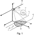
- the acquisition of SAR raw data based on radar pulses transmitted from a satellite will be described based on Fig. 1 .
- the satellite SA moves in the direction indicated by arrow M which is the direction along the x-axis of the Cartesian coordinate system shown in Fig. 1 .
- the direction along the x-axis is designated as the azimuth direction.
- the satellite SA flies at an altitude above the Earth's ground that is represented by the z-coordinate of the Cartesian coordinate system.
- the satellite SA comprises a radar sensor 1.
- this radar sensor 1 comprises several antenna elements 101, 102 and 103.
- the radar sensor 1 can comprise more or less of such antenna elements.
- the radar sensor is configured to transmit radar pulses through individual antenna elements at a predetermined pulse repetition frequency and to receive the echoes of the transmitted radar pulses through one or more antenna elements, which may include the element used for transmitting.
- the radar echoes are recorded by the radar sensor 1 and form the SAR raw data.
- a radar pulse transmitted by the radar sensor 1 is represented by its contour on the Earth's surface and is designated by reference numeral RP.
- the radar echo of each transmitted radar pulse is recorded by sampling the radar radiation reflected on ground in time.
- the propagation time is directly related to a range distance by the speed of light, while the propagation direction (range direction) varies along the y-axis of the Cartesian coordinate system.
- all the information of the radar echoes between the lines L and L' is recorded for each transmitted pulse. Both lines have a predetermined range distance that depend on the sensor and the imaging configuration and define the width of the imaged swath.
- the hatched region of the radar pulse RP indicates the information recorded by the radar sensor for each transmitted pulse.
- the acquired SAR raw data comprise data sets for several combinations of a transmitting antenna element and a receiving antenna element, where each transmit/receive combination is designated as a channel.
- Several antenna elements may receive and record the echoes of a single transmitted pulse at the same time, such that several channels can be acquired simultaneously.
- the data acquisition for each channel comprises data samples for a plurality of azimuth positions and a plurality of range positions.
- the principle of a SAR measurement is based on the fact that individual points on the Earth's ground are recorded from different angles due to the movement of the satellite SA. This is illustrated by point P in Fig. 1 .
- This point P is, in the scenario of Fig. 1 , at the point of closest approach to the satellite SA. By the movement of the satellite in the direction M, this distance will become greater. As the sensor approaches the position in Fig. 1 , on the other hand, this distance was decreasing. Due to the Doppler effect, a frequency shift of the recorded radar echoes occurs and can be analysed. As a consequence, all echoes from any given point can be coherently focussed to yield high resolution maps of scattering amplitude and phase. This information constitutes the final SAR image.
- the method described in the following determines appropriate external calibration factors and calibration constants for a SAR radar sensor, such as sensor 1 of Fig. 1 .
- a SAR radar sensor such as sensor 1 of Fig. 1 .
- radar echoes of reference targets with known radar cross sections and known positions on ground are recorded during the SAR data acquisition.
- the reference targets may be passive reflectors, such as dihedral or trihedral radar reflectors, or transponders that actively transmit signals in response to received radar pulses.
- the calibration factors and calibration constants are obtained directly from the SAR raw data without analysing SAR images derived therefrom.
- Conventional calibration methods are based on analysing SAR images and not the underlying SAR raw data.
- the diagram of Fig. 2 shows two flow charts separated by the vertical dashed line LI.
- the right flow chart refers to the calibration correction estimation, comprising several target analyses TA1, TA2, TA3, TA4 and TA5.
- the sub-steps of each of those target analyses are the same and are shown in the left flow chart of Fig. 2 .
- the calibration correction estimation uses as input IN the data acquisitions Dpq for each channel pq, where p denotes the index of a transmitting antenna element and q denotes the index of a receiving antenna element.
- the method begins with a target analysis TA1 which is repeatedly carried out in the course of the method.
- each target analysis comprises the following steps according to the left flow chart of Fig. 2 :
- the target analysis comprises another step between step S102 and step S103.
- This step is only relevant in view of the efficient implementation of the method in practice in that it does not impact the results obtained and is described in detail in section ⁇ 1.3 below.
- Each target analysis determines, from the SAR raw data Dpq, range compressed and clutter suppressed target data F pq s (see equation (27) below) for each reference target s, where s is an index denoting a corresponding particular reference target. Furthermore, the target analysis results in a residual phase ⁇ ⁇ pq s (see equation (34) below), a target coherence w pq s (see equation (35) below), a residual delay ⁇ pq s (see equation (38) below) and in an absolute RCS offset ⁇ RCS pq s (see equation (39) below), where RCS refers to the radar cross section of the corresponding reference target.
- RCS refers to the radar cross section of the corresponding reference target.
- step S4 the additional measurement ⁇ pq , uv s representing the residual interferometric phase between two channels is derived (see equation (63) below).
- IRF Impulse Response Function
- This step refers to the separate calibration procedure according to the terminology of the claims. A detailed description of this step is given in section ⁇ 2 below.
- the residual range IRF calibration results in a calibration factor ⁇ C e for each antenna element e (see equation (47) below).
- another target analysis TA2 is performed, where the calibration factor ⁇ C e is taken into account in equation (24) below.
- step S2 The result of the target analysis TA2 is processed in step S2 referring to the determination of antenna element mount angles.
- This step results in a calibration factor in the form of antenna element mount angle corrections ⁇ A e for each antenna element e (see equation (48) below).
- ⁇ A e antenna element mount angle corrections ⁇ A e for each antenna element e (see equation (48) below).
- ⁇ 3 A detailed description of this step is given in section ⁇ 3 below.
- Step S2 represents the first calibration procedure according to the terminology of the claims.
- step S2 another target analysis TA3 is performed, where the antenna element mount angle correction is taken into account in equation (16) below.
- the result of the target analysis TA3 is processed in step S3, which refers to the correction of antenna element lever arms.
- step S3 results in the calibration factor ⁇ L e for each antenna element e.
- ⁇ c a global correction to the speed of light, is determined in step S3. This global correction accounts for tropospheric propagation effects.
- Step S3 is described in detail in section ⁇ 4 below and represents the second calibration procedure according to the terminology of the claims.
- step S3 the target analysis TA4 is performed, where the calibration factor ⁇ L e is taken into account in equation (11) below and the tropospheric propagation correction ⁇ c is taken into account in equation (14).
- the result of target analysis TA4 is used in step S4, which refers to an antenna element baseline calibration resulting in the calibration factor ⁇ L e inf .
- step S4 the additional measurement ⁇ pq , uv s , as defined in equation (63) below, is used.
- Step S4 corresponds to the third calibration procedure in the terminology of the claims. Step S4 is described in detail in section ⁇ 5 below
- the calibration factor ⁇ L e inf is added to the calibration factor ⁇ L e determined in step S3, resulting in an updated and refined calibration factor ⁇ L e .
- the target analysis TA5 is performed.
- the result of the target analysis TA5 is thereafter used to determine calibration constants according to step S5. Step S5 is described in detail in section ⁇ 6 below.
- the method described herein results in calibration factors ⁇ C e , ⁇ A e , ⁇ L e and ⁇ L e inf as well as in calibration constants. Those quantities can now be applied during the processing of new SAR data acquisitions of the radar sensor, thus resulting in calibrated SAR data and SAR images.
- the tropospheric propagation correction ⁇ c is estimated to allow the unbiased estimation of ⁇ L e , but may not be useful in processing new acquisitions, as tropospheric conditions change with time.
- pq s A quantity derived from the response of reference target s in a channel that uses antenna elements p and q to transmit and receive signals, respectively.
- D pq ( t', ⁇ ) Raw measurement data acquired in channel pq C pq ( t', ⁇ ) Internal calibration data acquired for channel pq , obtained by recording pulses that have traversed the transmit- and receive-channels in the instrument.
- These coordinates correspond to a specific point on the sensor platform, referred to as the instrument reference point in the following.
- the attitude angles measure the sensor roll (subscript r ), pitch (subscript p ) and yaw (subscript y ) and relate the global (x,y,z) coordinate system to the so-called Cartesian instrument coordinate system.
- the latter has coordinate axes denoted (u,v,w) and is centred on the instrument reference point such that any particular point on the sensor has an instrument coordinate that is constant over time.
- R (t) is a 3x3 rotation matrix derived from the attitude angles A(t).
- the precise definition of the rotation depends on the conventions adopted for the coordinate systems and attitude angles.
- the SAR instrument i.e. the radar sensor
- each element may transmit and receive signals in horizontal (H) or vertical (V) polarisation.
- H or V the two modes of operation
- the on-ground characterisation of the antenna array provides the following information concerning each particular element e of the array:
- the radar sensor provides multiple channels of complex SAR raw data D pq ( t', ⁇ ) as well as the corresponding internal calibration measurements C pq ( t', ⁇ ).
- the subscript pq identifies the data channel by the particular combination antenna array elements employed to transmit pulses (element p ) and receive echoes (element q ).
- SAR data acquired for calibration purposes always use individual antenna elements on transmit and receive, as the use of multiple elements would imply beam-forming, which in turn requires accurate array calibration to already have been carried out.
- the dimensions of the raw data are t' , which is related to the discrete time t defined above, and ⁇ , the so-called fast time, which measures the comparatively short duration between pulse transmission the time at which a particular raw data sample is received and recorded.
- t' and ⁇ denote sample indices that can, however, be easily converted to physical units.
- o pq denotes the offset of a particular transmit/receive combination within the sequence.
- the internal calibration data C pq ( t', ⁇ ) characterises propagation effects in the radar by providing a record of the transmitted pulse that has bypassed the antenna and was fed back directly into the receive path.
- calibration pulses are recorded on a pulse-to-pulse basis using the actual signal pathways employed for the particular transmit and receive element combination.
- the calibration data may not be acquired for each pulse, such that it needs to be interpolated in time, or may not cover every transmit/receive combination, in which case the same calibration data must be re-used for several pulses in the sequence.
- Sensor calibration data takes are acquired over test-sites with dedicated reference targets.
- the relevant properties of these targets must be measured to a high degree of accuracy to allow for a meaningful comparison between the expected radar return and the actual SAR measurements.
- the relevant properties for a given reference target s are:
- the analysis of reference targets in the acquired calibration SAR data is the central building block of the calibration approach.
- the analysis comprises the selection and pre-processing of relevant parts of the input data and the subsequent extraction of information necessary for estimating calibration corrections. It is repeated for each valid reference target s in each SAR data channel pq acquired, where valid targets are those that can be expected to produce a response in the channel under consideration. Analysis does not, therefore, cover targets that are misaligned or do not produce a response for the transmit and receive antenna element polarisations in a particular SAR data channel.
- the process begins with pre-processing the navigation data.
- the tropospheric propagation correction ⁇ c is specific to the calibration acquisition under consideration and is not transferrable to other data takes. This is due to the fact that tropospheric conditions may change in time and, in the spaceborne case, the thickness of the troposphere between the reference target and the sensor changes depending on the altitude of the reference target (note that the form of the correction in eq. (14) assumes that all reference targets in a single calibration acquisition are at roughly the same altitude). The correction is nevertheless important, as it removes tropospheric bias from other corrections, such as the antenna lever arms and the residual range delays, which are then transferred to other data takes.
- the expected brightness of a given reference target in the SAR data acquired depends on the antenna element illumination in the direction of the target as a function of time as well as on the intrinsic brightness of the target.
- the intrinsic brightness of the reference target as a function of frequency and time is obtained from the target RCS by applying equations (9) and (10) to the element phase centre positions in global coordinates:
- the radar returns of a single reference target in a single data channel occupy a small fraction of the total raw data constituting the calibration data acquisition.
- the first step of radar data analysis is therefore to determine the extent of the raw data to be analysed for a single target in a single channel.
- the analysis limits must include at least those samples that cover the relevant portion of the antenna beam, i.e. the part that will be used in operational imaging modes.
- the mask in range direction, M rg ( t', ⁇ ), includes the samples required for pulse compression (for a given pulse duration PD ) at each azimuth time t' and a constant margin ⁇ marg to account for residual range delays. It also accounts for internal delays within the radar instrument, ⁇ pq ( t' ) .
- M rg t ′ , ⁇ ⁇ 1 if ⁇ PD 2 ⁇ ⁇ ⁇ ⁇ pq s t ′ + ⁇ pq t ′ ⁇ PD 2 + ⁇ marg 0 otherwise .
- the instrument delay term is composed of the delay measurement that is part of the internal calibration data and an external calibration delay measurement.
- ⁇ pq t ′ ⁇ ⁇ p + ⁇ ⁇ q + ⁇ ⁇ pq int t ′ , where ⁇ ⁇ pq int t ′ is the two-way propagation delay that can be derived from the internal calibration signal C pq ( t', ⁇ ) and ⁇ ⁇ e ⁇ p,q ⁇ denote residual one-way propagation delays through the respective antenna elements that are not captured by internal calibration measurements. The latter are initially zero but take non-zero values when reference target analysis is repeated later on in the calibration process.
- mapping F [ f ] converts the frequency sample index f into a physical frequency measured in Hz, taking into account the centre frequency f 0 and the range sampling frequency RSF.
- the calibration corrections ⁇ C e ⁇ p,q ⁇ ( f ) and ⁇ ⁇ e ⁇ p,q ⁇ denote residual corrections to the one-way frequency response and the one-way propagation delay of antenna elements p and q. They are initially 1 (for ⁇ C e ⁇ p,q ⁇ ) and 0 (for ⁇ ⁇ e ⁇ p,q ⁇ ) but take different values when reference target analysis is repeated later on in the calibration process.
- the range compressed raw data D pq s t ′ , ⁇ ′ contains, in addition to the reference target response, unwanted contributions from other targets elsewhere in the imaged scene. This "clutter" contribution needs to be suppressed as far as possible before the target response can be meaningfully analysed.
- This transformation is essentially equivalent to performing an azimuth compression of the reference target response where, because the phase has been flattened in the application of eq. (23), ambiguities in the target response due to azimuth under-sampling of the raw data channel no longer occur.
- the standard deviation ⁇ of the Gaussian filter is chosen to maximise clutter suppression while preserving features of the response down to the angular resolution in azimuth required for the accurate estimation of calibration corrections.
- Equation (33) assumes that the FFT and IFFT operations follow the generally accepted convention by using scaling factors of 1 and 1 / N az ′ , respectively.
- the amount of residual clutter energy is of central importance to the approach as a whole, as it quantifies the amount of noise that ultimately limits the accuracy of the calibration corrections derived.
- phase correction of eq. (25) ensures that azimuth under-sampling is not an issue for the reference target response itself, such under-sampling will increase the residual clutter energy due to aliased clutter contributions.
- the clutter filtered, range compressed raw data F pq s is used to derive several vector quantities to be used later in the calibration process.
- the residual phase measures phase errors in the target response that are related to inaccuracies in the navigation data and the antenna element lever arms.
- ⁇ pq s t ′ arg ⁇ ⁇ ′ F pq s t ′ , ⁇ ′ .
- the convolution may, for example, correspond to a moving average with on the order of 100 samples.
- ⁇ coarse t ′ argmax ⁇ ′ F pq s t ′ , ⁇ ′
- a sub-sample refinement to the initial, coarse estimate is obtained by estimating a phase gradient in the frequency domain.
- the analysis of the filtered raw data with respect to the radar cross section aims to derive the absolute, unit-less offset, in dB, between the expected and the measured RCS of the reference target.
- equation (23) has already accounted for systematic intensity variations due to antenna element gains and the expected target RCS, the derivation of the absolute RCS offset from the filtered data must also include additional terms from the radar equation for real-aperture radar and compensate for the residual clutter intensity of eq.
- the aim of the residual range impulse response calibration is to measure systematic, frequency dependent amplitude and non-linear phase variations that occur within the pulse bandwidth when internal calibration measurements fail to faithfully reproduce the transfer function of the radar instrument. Corresponding corrections are estimated for each individual antenna element and are assumed to be reciprocal, i.e. identical on transmit and receive.
- H pq s t ′ , f FFT ⁇ ⁇ f F pq s t ′ , ⁇ ′ ⁇ ⁇ ′ F pq s t ′ , ⁇ ′ e ⁇ 2 ⁇ j F f ⁇ pq s t ′ / N rg , where, as above, N rg denotes the number of samples in range and F [ f ] maps the frequency index f to a physical frequency in Hz.
- H pq s represents the normalised frequency response of the target at each azimuth time t' , in which the overall energy is unity and linear phase ramps over frequency f have been removed by compensating for propagation time variations ⁇ pq s .
- the error functions defined above use the L1-norm, rather than quadratic errors, to reduce the impact of outliers on the solution.
- the small, positive number ⁇ opt is introduced for numerical stability only; it is set to 10 -4 .
- the approach taken is to choose the attitude corrections that minimise variations in the RCS offsets ⁇ RCS pq s of eq. (39).
- ⁇ RCS e is the unknown constant gain offset, in dB and assumed reciprocal, affecting the signal after propagating through antenna element e
- ⁇ Gain e s t ′ denotes the change in the antenna gain, in dB and at the centre frequency, due to mount angles ⁇ A e at each azimuth position t'.
- the optimisation uses a L1-error function to reduce the impact of outliers and needs to be carried by iteratively solving re-weighted least-squares problems.
- the minimisation of errors of the form (49) is complicated, however, by the non-linearity of eq. (51) in terms of attitude corrections ⁇ A e .
- the first step is therefore to derive a linear approximation of Gain e s that is valid close to a given value of ⁇ A e : Gain e s t ′ , ⁇ A e + ⁇ e ⁇ Gain e s t ′ , ⁇ A e + g e s , roll t ′ g e s , pitch t ′ g e s , yaw t ′ ⁇ ⁇ e roll ⁇ e pitch ⁇ e yaw .
- the local gradients g e s , roll g e s , pitch g e s , yaw are computed numerically from the changes in Gain e s when ⁇ A e is perturbed in the respective angular dimension.
- the determination of antenna element mount angles is then carried out as a fixed point iteration.
- the system consists of one equation for each azimuth sample t' of each raw data channel pq and each reference target s and is solved using standard least-squares approaches.
- the corrections ⁇ e are applied additively to the current ⁇ A e and the functions ⁇ Gain e s and numerical gradients g e s , roll g e s , pitch g e s , yaw are updated accordingly.
- the iteration terminates once the antenna element mount angles have converged.
- the reference target analysis described in section ⁇ 1 is then repeated, where the estimated mount angle corrections are taken into account in eq. (16), before proceeding with further calibration steps.
- the above procedure must be modified to ensure that a single physical antenna element is associated with only one mount angle, instead of separate mount angles for the H and V polarisations. This is achieved by simply reducing the number of unknowns by symbolically setting ⁇ A p ⁇ ⁇ A q for pairs of logical elements p and q that correspond to the same physical antenna element.
- the positions of the antenna element phase centres are refined in two steps.
- the first step described in this section, derives relatively coarse positions that are accurate to within the limits set by residual errors affecting the input navigation data and the assumed reference target positions. This coarse estimate also accounts for a residual tropospheric propagation delay, modelled as a correction to the speed of light.
- the optimisation process uses two error functions that essentially separate the effects of element lever arm related errors into the range and azimuth dimensions.
- This error function aims to explain the observed reference target range offsets ⁇ ⁇ pq s of eq. (38) in terms of the projection of lever arm refinements ⁇ L e onto the line-of-sight vectors los e s of eq. (13) in combination with a tropospheric propagation correction ⁇ c and residual element propagation delays ⁇ r e , measured in metres rather than seconds to avoid introducing a non-linearity.
- ⁇ L e , ⁇ c and ⁇ r e are considered unknown variables, and the range position error is summed over azimuth time t' using the target coherence w pq s of eq. (35) as a weight to yield a single error term for each data channel pq and reference target s.
- the azimuth error function is similar to that of eq. (55) and penalises residual phase variations that can be reduced by introducing appropriate lever arm and tropospheric propagation corrections.
- the variable O pq s treated as an unknown specific to each channel pq and reference target s , can be considered an auxiliary variable that absorbs offsets due to residual propagation delays in the sensor as well as arbitrary constant phase offsets. Its value is estimated but is, in itself, not useful for the purpose of sensor calibration.
- the error functions use the L1-norm instead of quadratic penalties to reduce the impact of outliers on the optimisation.
- section ⁇ 1 is carried out anew for all data channels and reference targets to ensure that the updated calibration corrections are taken into account before proceeding further.
- the reference target analysis of section ⁇ 1 is carried out anew for all data channels and reference targets to ensure that the updated calibration corrections are taken into account before proceeding further.
- it becomes necessary to repeat the entire estimation process cumulating corrections ⁇ L e and ⁇ ⁇ e .
- a further refinement of the antenna element phase centre position is possible using interferograms between filtered, range-compressed raw data channels derived for the same reference target.
- the refined estimate is independent of residual errors in the navigation data and the reference target positions.
- the two approaches are complementary in that the interferometric approach cannot determine absolute phase centre positions or accurately characterise tropospheric propagation effects. Instead, it yields highly accurate estimates of the spatial separation, or baseline, between antenna element phase centres.
- these phases must first be unwrapped. To ensure that the interferometric phase information for different reference targets remains consistent, which is necessary for 3D baseline refinement, this phase unwrapping must be carried out in two dimensions.
- phase unwrapping algorithm for irregular grids yields unwrapped phase vectors ⁇ ⁇ pq , uv 1 , UW t , ⁇ ⁇ pq , uv 2 , UW t , ⁇ ⁇ pq , uv 3 , UW t ... .
- bias due to potential unwrapping errors is minimised by restricting the analysis to the largest connected set of phase measurements with a combined coherence w pq s ⁇ w uv s above a certain threshold, where connectivity is defined in terms of the 2D triangulated mesh of measurement points.
- the estimation of phase calibration constants requires that phase unwrapping preserves the average phase of the input samples.
- the system of equations must include three equations to account for
- the final set of calibration constants is re-derived as follows:
- phase calibration constants ⁇ ⁇ pq,uv do not need to be re-estimated, as they are the product of the last calibration correction. These constants are, however, not specific to individual antenna elements but to a particular data channel combination, such that a post-processing step is required to derive per-element corrections.
- the presence of integer valued unknowns makes this problem very difficult to solve in general.
- the proposed approach is comparatively simple but imposes constraints on the combination of data channels available for calibration. This approach can be summarised as follows:
- step 2 The constraint on the data channels made available for calibration is that the condition in step 2 must be fulfilled in each iteration. Having initialised a single ⁇ ⁇ e in step 1, it implies that the calibration data set includes channels corresponding to antenna element combinations ee and eq for the derivation of ⁇ ⁇ q via ⁇ ⁇ ee,eq . After two elements are associated with phase calibration constants, there is an increasing amount of freedom in the channel combinations sufficient for calibration.
- the over-determined system of equations represented by eq. (73) is easy to solve using standard least-squares techniques to obtain refined element-wise phase calibration constants based on the full set of possible interferometric channel combinations.
- the antenna element mount angles ⁇ A e are not affected, provided that the transmit and receive elements have different antenna illumination diagrams.
- the initialisation of the iterative algorithm for the element-wise phase calibration of the array in section ⁇ 6 must be adjusted: instead of initialising a single phase calibration constant ⁇ ⁇ e in step 1, it is necessary to initialise two constants ⁇ ⁇ u and ⁇ ⁇ v , where u and v correspond to one transmit and one receive antenna element.
- Multistatic SAR involves the joint analysis and processing of radar data acquired by a formation of independent SAR sensors. If each SAR sensor in the formation can both receive and transmit signals, each can be calibrated as a monostatic system using the approaches described. Should this not be the case, however, the entire formation must be jointly calibrated.
- the invention as described in the foregoing has several advantages. It provides an accurate calibration of multi-channel SAR instruments, such as those required to support SAR polarimetry, single-pass interferometry and digital beam-forming, on the basis of dedicated SAR acquisitions containing reference targets with known properties.
- the method is based on the analysis of range compressed raw data. It does not require SAR image focussing in azimuth, which is essential in cases where azimuth focussing requires beam-forming techniques and thus presupposes an accurate calibration of the antenna array.
- the method assumes that the internal calibration sub-system of the sensor is able to effectively compensate for transient drifts due to propagation effects within the radar instrument.
- the focus is, instead, on providing an accurate and consistent characterisation of the antenna array, which is, by definition, outside the scope of internal calibration techniques.
- the approach introduces an explicit model of possible calibration error sources and uses SAR measurements to derive corresponding corrections.
- the error sources considered, for each antenna element in an array are as follows:
- results of the analyses carried out for each point in the above list serve the dual purpose of validation. They provide a granular picture of the calibration corrections required that can then be assessed with respect to prior expectations to pinpoint issues related to the on-ground characterisation process, the internal calibration and navigation sub-systems and the sensor deployment process. Regular calibration data takes enable detailed monitoring of the instrument stability, especially with respect to the performance of the antenna array, and the introduction of additional corrections when and if they become necessary.
- the proposed calibration technique as described herein is fundamentally different to existing approaches in that it is based on the analysis of the response of reference targets in range compressed raw data.
- Conventional external calibration approaches by contrast, use focussed SAR imagery, while data-driven approaches that are based on range compressed SAR data do not take advantage of reference targets.
- the following description highlights specific, unique characteristics of the proposed approach that largely stem from this fundamental difference.
- the names of particular processing steps are typeset in bold and refer to the flowcharts of Fig. 2 .
- the pre-processing of SAR raw data includes a Response Correction that, among other things, removes aliasing from the reference target response of each individual data channel without resorting to beam-forming techniques.
- a Response Correction that, among other things, removes aliasing from the reference target response of each individual data channel without resorting to beam-forming techniques.
- Existing calibration techniques do not apply to sub-sampled data or use beam-forming techniques that are problematic when applied before the antenna array is fully calibrated.
- Pre-processing also includes a novel filtering operation for Clutter Suppression , in which the response of the reference target is cleanly separated out by suppressing backscatter contributions from other parts of the imaged scene.
- the Residual Error Analysis identifies residual deviations from the expected reference target response in terms of range position, phase and backscatter intensity.
- this analysis captures variations within the illumination time, i.e. along azimuth.
- the analysis yields the target radar cross section (RCS) as measured by each received echo in the radar raw data by applying the radar equation for real aperture radar.
- RCS target radar cross section
- the Residual Range IRF analysis uses a robust (L1-Norm minimisation) algorithm for estimating residual, radar frequency-dependent amplitude and phase variations.
- This optimisation algorithm explicitly takes into account the frequency response measured in each echo received from reference targets and has not been used in this context before. The approach makes the estimates derived more robust with respect to outliers caused by residual clutter and radio frequency interference.
- the Element Mount Angles estimation introduces pointing corrections that minimise the observed RCS deviations, taking into account the sensor attitude angles and possible variations thereof during the illumination time.
- Other calibration approaches do not include such mount angles at all, such that both the error model used and the estimation algorithm can be considered novel.
- the approach includes a two-step refinement of antenna element phase centre positions.
- the first step Element Lever Arms , provides coarse corrections that minimise the observed range position discrepancies and phase errors along azimuth (I.e. during the illumination time).
- the underlying error model and the estimation algorithm differ from existing approaches in that:
- step S5 referring to the determination of calibration constants, may be omitted in specific embodiments of the invention.
- steps S101 to S05 of the reference target analysis may be implemented in a different way as long as target data for each channel and each reference target are extracted appropriately.
- the clutter suppression of step S104 may be omitted in case that the SAR raw data comprise little or no clutter.
Landscapes
- Engineering & Computer Science (AREA)
- Remote Sensing (AREA)
- Radar, Positioning & Navigation (AREA)
- Physics & Mathematics (AREA)
- Computer Networks & Wireless Communication (AREA)
- General Physics & Mathematics (AREA)
- Electromagnetism (AREA)
- Radar Systems Or Details Thereof (AREA)
Abstract
Description
- The invention refers to a method and an apparatus for computer-assisted processing of SAR raw data.
- Synthetic aperture radar (SAR) is a technique for remote sensing that is being used increasingly in imaging, monitoring and investigation on the earth's surface. A SAR radar system consists of a flying object, e.g. a satellite or an airplane, which moves at a constant speed, and a radar sensor that points in a direction orthogonal to the direction of motion. The radar sensor periodically transmits electromagnetic waves and records the echoes of those waves reflected on ground.
- In standard SAR sensor operation, SAR raw data acquisitions are followed by a computationally intensive processing step called image formation or SAR focussing in which echoes recorded in the SAR raw data are back-projected onto the ground to yield the actual image of the scene. To provide useful results, this processing must also ensure an accurate sensor calibration that enables users of the data to relate the SAR sensor measurement to physical parameters of interest and geolocate this information.
- SAR sensor calibration consists of an internal calibration and an external calibration. The internal calibration is based on measurements performed internally by the SAR sensor itself. These measurements typically use dedicated hardware to regularly monitor the sensor state that can later be used to compensate for temporal variations in the transmitted electromagnetic wave and any signal distortions that occur when echoes from the image scene are received and recorded.
- External SAR sensor calibration is based on the analysis of reference targets with known radar cross sections and positions on ground. The reference targets may be active transponders that transmit signals in response to incoming radar pulses or passive reference targets, such as dihedral of trihedral radar reflectors, which reflect transmitted radar pulses back towards the radar sensor.
- Conventionally, external calibration is based on the SAR images derived from the SAR raw data. To do so, calibration factors are determined based on a comparison of the characteristics of the reference targets in the SAR images with the known characteristics of these reference targets. This calibration is very complex, as it requires SAR images and therefore SAR image formation on the basis of SAR raw data.
- It is an object of the invention to provide a method for computer-assisted processing of SAR raw data that establishes an external calibration in an easy and efficient way.
- This object is solved by the method according to claim 1 and the apparatus according to claim 11, respectively. Preferred embodiments of the invention are described in the dependent claims.
- The method of the invention provides a computer-assisted processing of SAR raw data, comprising radar echoes from ground (i.e. the earth's surface) that are the response to radar pulses that have been transmitted by antenna elements of a radar sensor on at least one flying object (e.g. a single flying object) moving in an azimuth direction above ground and where the radar echoes have been received by antenna elements of the radar sensor. The flying object may refer to an airplane, a satellite or the like. The SAR raw data comprise several data channels, each of which includes radar echoes originating from reference targets with known radar cross sections and positions on ground. Each channel is identified by the combination of two antenna elements used to transmit pulses and receive echoes, and the data acquisition for a channel comprises a plurality of data samples for several azimuth positions and several range positions, the range positions corresponding to different distances from the radar sensor to ground.
- The method of the invention comprises one or more calibration procedures. Each calibration procedure includes steps i) and ii) described in the following. Step i) uses the known radar cross section and position on ground for each reference target in order to extract target data for each reference target in each channel from the SAR raw data and in order to determine a variation of one or more measurements over different radar echoes (i.e. radar echoes received in response to different radar pulses) originating from each reference target for each channel or for each combination of two channels based on the target data. The term "measurement" is to be interpreted broadly and may refer to any value which can be derived from the target data. The term "measurement" was chosen because the target data are based on SAR raw data which form measured values.
- In a step ii), one or more calibration factors in the form of one or more correction terms for one or more sensor parameters of the radar sensor are determined based on an optimisation comprising the optimisation goal to (simultaneously) minimise the variation of one or more measurements for all reference targets and for all channels or all combinations of two channels. The above minimisation can be defined in terms of corresponding error functions, where examples of such error functions are given in the detailed description.
- In a preferred embodiment, the measurements defined above refer to a residual phase and/or to a residual delay and/or to the difference between two residual phases for two channels and/or to a radar cross section offset. These quantities are defined as described with respect to embodiments explained later on. Furthermore, the one or more sensor parameters preferably refer to antenna mount angles of each antenna element and/or relative positions of the phase centres of the antenna elements with respect to a reference position on the at least one flying object.
- The method of the invention has the advantage that calibration factors can be derived from the SAR raw data without focusing corresponding SAR images. This is especially important in situations where image focusing presupposes precise calibration (e.g. for sensors that employ beamforming). In addition, the approach provides a systematic way for analysing and correcting propagation direction dependent calibration issues, which is not the case for conventional techniques. Calibration is achieved by an optimisation designed to minimise the variation of measurements for all reference targets and for all channels or all combinations of two channels. The invention results in reliable calibration factors that can be used to improve image quality when processing new SAR raw data acquired by the radar sensor over areas that do not include reference targets. To do so, the calibration factors are applied to the respective sensor parameters during SAR image focusing.
- In a preferred embodiment of the method according to the invention, the one or more calibration procedures comprise a first calibration procedure. In this first calibration procedure, the variation of a measurement determined in step i) refers to the variation of a radar cross section offset over different radar echoes originating from each reference target in each channel. Furthermore, correction terms for sensor parameters in the form of antenna mount angles of each antenna element on the at least one flying object are determined in step ii). In this embodiment, the radar cross section offset represents the difference between the known radar cross section and the radar cross section according to the target data for the respective reference target and the respective channel.
- In another embodiment of the invention, the one or more calibration procedures comprise a second calibration procedure. According to the second calibration procedure, the variation of a measurement determined in step i) refers to the variation of a residual phase over different radar echoes originating from each reference target in each channel. In this embodiment, correction terms for sensor parameters in the form of relative positions of the phase centres of the antenna elements with respect to a reference position on the at least one flying object are determined in step ii). The residual phase for a respective channel represents the difference between the (expected) phase of a radar echo based on the positions of the transmitting and receiving antenna element phase centres of the respective channel and based on the known position of the respective reference target on ground on the one hand and the phase according to the target data for the respective reference target on the other hand. In a preferred variant of this embodiment, the optimisation within the second calibration procedure includes the additional optimisation goal to minimise the mean residual delay over different radar echoes originating from each reference target in each channel, where the residual delay for a respective channel represents the difference between the (expected) propagation time from transmitting a radar pulse until receiving its radar echo based on the positions of the transmitting and receiving antenna element phase centres of the respective channel and based on the known position of the respective reference target on ground on the one hand and the corresponding propagation time according to the target data for the respective reference target on the other hand. In case that embodiments refer to positions of the transmitting and receiving antenna element phase centres, these positions can be determined with well-known methods during data acquisition, e.g. by using a navigation system of the at least one flying object. These positions initially contain residual errors which may later be compensated by calibration factors.
- According to another embodiment, the one or more calibration procedures comprise a third calibration procedure. According to this third calibration procedure, the variation of a measurement determined in step i) refers to the variation of the difference between two residual phases for two (different) channels over different radar echoes originating from each reference target in each combination of two (different) channels. Furthermore, correction terms for sensor parameters in the form of relative positions of the phase centres of the antenna elements with respect to a reference position on the at least one flying object are determined in step ii). In this embodiment, the residual phase for a respective channel represents the difference between the phase of a radar echo based on the positions of the transmitting and receiving antenna element phase centres of the respective channel and based on the known position of the respective reference target on ground on the one hand and the phase according to the target data for the respective reference target on the other hand. The third calibration procedure is preferably performed as a refinement of the above described second calibration procedure.
- With respect to the first, second and third calibration procedures defined above, the method can comprise any combination of those calibration procedures or only one of those calibration procedures. In a preferred embodiment, the method comprises the first and the second and the third calibration procedures, resulting in very accurate calibration factors. Preferably, the third calibration procedure is performed after the second calibration procedure and the second calibration procedure is performed after the first calibration procedure.
- In a preferred variant, the method according to the invention comprises several calibration procedures which are performed based on an iteration, where each calibration procedure constitutes an iteration step and where step i) of an iteration step (i.e. the associated calibration procedure) takes into account one or more calibration factors determined in all preceding iteration steps. This embodiment enables an improved calibration by iteratively combining several calibration procedures.
- In another embodiment of the invention, the extraction of target data for each reference target and each channel in step i) of at least one calibration procedure comprises a well-known range compression as well as a correction based on the known radar cross section and the known position of the respective reference target on ground. In a preferred variant of this embodiment, the correction is further based on the antenna diagrams of the transmitting and receiving antenna elements associated with the respective channel and/or based on the expected propagation time from the phase centre of the transmit antenna element to the respective reference target and back to the phase centre of the receive antenna element in the respective channel and/or based on internal calibration data acquired by recording pulses that have traversed the same transmit and receive branches in the radar sensor as target data in the respective channel. The expected propagation time is determined based on the positions of the transmitting and receiving antenna element phase centres of the respective channel and based on the known position of the respective reference target on ground.
- In another preferred embodiment, the extraction of target data for each reference target and each channel in step i) of at least one calibration procedure comprises a clutter suppression operation for suppressing radar echoes originating from scatterers other than the respective reference target.
- In another preferred embodiment, the method of the invention comprises a separate calibration procedure in addition to the one or more calibration procedures, where the separate calibration procedure comprises steps a) and b) described in the following. According to step a), by using the known radar cross section and position on ground for each reference target, target data for each reference target in each channel are extracted from the SAR raw data and the variation of a residual delay over different radar echoes originating from each reference target in each channel is determined. The residual delay for a respective channel represents the difference between the (expected) propagation time from transmitting a radar pulse until receiving its radar echo based on the positions of the transmitting and receiving antenna element phase centres of the respective channel and based on the known position of the respective reference target on ground on the one hand and the corresponding propagation time according to the target data for the respective reference target on the other hand.
- According to step b), frequency-dependent phase and amplitude variations within the bandwidth of the radar echoes are estimated by determining calibration factors in the form of correction terms for the respective antenna elements based on a (simultaneous) minimisation of error functions, where at least one error function (preferably two error functions) is defined over different radar echoes originating from each reference target in each channel. The at least one error function is defined based on a frequency response function for each radar echo originating from the respective reference target in the respective channel, where the frequency response function is derived from the target data and the variation of the residual delay obtained in step a). The above calibration factors can be applied to the respective antenna elements during SAR image focusing.
- In a preferred variant of the above embodiment, the separate calibration procedure is part of the above defined iteration and forms an iteration step therein, where step i) of all iteration steps (if any) after the iteration step of the separate calibration procedure takes into account the correction terms determined in step b). In one embodiment, the separate calibration procedure is performed before any other calibration procedure.
- In another preferred embodiment of the method according to the invention, after performing the one or more calibration procedures, one or more calibration constants, particularly a gain and/or delay and/or phase shift for each (individual) antenna element, are determined. These calibration constants are provided to be applied in a later processing of other SAR raw data as overall, constant corrections to the entire SAR raw data set or entire images derived from the SAR raw data.
- Besides the above method, the invention also refers to an apparatus for computer-assisted processing of SAR raw data, comprising radar echoes from ground that are the response to radar pulses that have been transmitted by antenna elements of a radar sensor on at least one flying object moving in an azimuth direction above ground and where the radar echoes have been received by antenna elements of the radar sensor. The SAR raw data comprise several data channels, each of which includes radar echoes originating from reference targets with known radar cross sections and positions on ground. Each channel is identified by the combination of two antenna elements used to transmit pulses and receive echoes, and the data acquisition for a channel comprises a plurality of data samples for several azimuth positions and several range positions, the range positions extending in a range direction perpendicular to the azimuth direction. This apparatus is configured to perform the method according to the invention or one or more preferred embodiments thereof. In other words, the apparatus comprises means in the form of hardware and/or software in order to perform steps i) and ii) as defined in claim 1.
- The invention also refers to a computer program product comprising program code stored on a machine readable medium, where the program code is configured to perform a method according to the invention or one or more preferred embodiments thereof, when the program code is run on a computer.
- Furthermore, the invention refers to a computer program comprising program code which is configured to perform a method according to the invention or one or more preferred embodiments thereof, when the program code is run on a computer.
- In the following, embodiments of the invention will be described in detail with respect to the accompanying drawings wherein:
- Fig. 1
- is a schematic drawing illustrating the acquisition of SAR raw data in the context of the invention; and
- Fig. 2
- shows flow charts describing the steps performed in an embodiment of the invention.
- For better understanding, the acquisition of SAR raw data based on radar pulses transmitted from a satellite will be described based on
Fig. 1 . When acquiring the SAR raw data, the satellite SA moves in the direction indicated by arrow M which is the direction along the x-axis of the Cartesian coordinate system shown inFig. 1 . The direction along the x-axis is designated as the azimuth direction. The satellite SA flies at an altitude above the Earth's ground that is represented by the z-coordinate of the Cartesian coordinate system. The satellite SA comprises a radar sensor 1. As can be seen from the detailed view DT inFig. 1 , this radar sensor 1 comprisesseveral antenna elements Fig. 1 , a radar pulse transmitted by the radar sensor 1 is represented by its contour on the Earth's surface and is designated by reference numeral RP. - The radar echo of each transmitted radar pulse is recorded by sampling the radar radiation reflected on ground in time. The propagation time is directly related to a range distance by the speed of light, while the propagation direction (range direction) varies along the y-axis of the Cartesian coordinate system. In the embodiment shown in
Fig. 1 , all the information of the radar echoes between the lines L and L' is recorded for each transmitted pulse. Both lines have a predetermined range distance that depend on the sensor and the imaging configuration and define the width of the imaged swath. The hatched region of the radar pulse RP indicates the information recorded by the radar sensor for each transmitted pulse. - The acquired SAR raw data comprise data sets for several combinations of a transmitting antenna element and a receiving antenna element, where each transmit/receive combination is designated as a channel. Several antenna elements may receive and record the echoes of a single transmitted pulse at the same time, such that several channels can be acquired simultaneously. In the embodiment of
Fig. 1 , there are nine channels as each antenna element can transmit radar pulses and receive radar echoes. The data acquisition for each channel comprises data samples for a plurality of azimuth positions and a plurality of range positions. - The principle of a SAR measurement is based on the fact that individual points on the Earth's ground are recorded from different angles due to the movement of the satellite SA. This is illustrated by point P in
Fig. 1 . This point P is, in the scenario ofFig. 1 , at the point of closest approach to the satellite SA. By the movement of the satellite in the direction M, this distance will become greater. As the sensor approaches the position inFig. 1 , on the other hand, this distance was decreasing. Due to the Doppler effect, a frequency shift of the recorded radar echoes occurs and can be analysed. As a consequence, all echoes from any given point can be coherently focussed to yield high resolution maps of scattering amplitude and phase. This information constitutes the final SAR image. - The method described in the following determines appropriate external calibration factors and calibration constants for a SAR radar sensor, such as sensor 1 of
Fig. 1 . To enable this external calibration, radar echoes of reference targets with known radar cross sections and known positions on ground are recorded during the SAR data acquisition. As an example, the locations of such reference targets RT are indicated inFig. 1 . The reference targets may be passive reflectors, such as dihedral or trihedral radar reflectors, or transponders that actively transmit signals in response to received radar pulses. According to the invention, the calibration factors and calibration constants are obtained directly from the SAR raw data without analysing SAR images derived therefrom. Conventional calibration methods, on the other hand, are based on analysing SAR images and not the underlying SAR raw data. - In the following, a general outline of the steps performed according to an embodiment of the invention will be described with respect to
Fig. 2 . Thereafter, a detailed mathematical description of the corresponding steps indicated inFig. 2 is given. - The diagram of
Fig. 2 shows two flow charts separated by the vertical dashed line LI. The right flow chart refers to the calibration correction estimation, comprising several target analyses TA1, TA2, TA3, TA4 and TA5. The sub-steps of each of those target analyses are the same and are shown in the left flow chart ofFig. 2 . The calibration correction estimation uses as input IN the data acquisitions Dpq for each channel pq, where p denotes the index of a transmitting antenna element and q denotes the index of a receiving antenna element. The method begins with a target analysis TA1 which is repeatedly carried out in the course of the method. In order to distinguish between the target analyses, different reference numerals TA1, TA2, TA3, TA4 and TA5 are used although the sub-steps in each analysis are the same and correspond to the sub-steps shown in the left flow chart ofFig. 2 . - In particular, each target analysis comprises the following steps according to the left flow chart of
Fig. 2 : - Step S101, referring to the quantitative description of the acquisition geometry, where this step will be explained in detail in section § 1.1 below;
- Step S102, referring to the determination of a response model, where this step will be explained in detail in section § 1.2 below;
- Step S103, referring to a response correction, where this step will be explained in detail in section § 1.4 below;
- Step S104, referring to a clutter suppression, where this step will be explained in detail in section § 1.5 below;
- Step S105, referring to the residual error analysis, where this step will be explained in detail in section § 1.6 below.
- Furthermore, the target analysis comprises another step between step S102 and step S103. This step is only relevant in view of the efficient implementation of the method in practice in that it does not impact the results obtained and is described in detail in section § 1.3 below.
- Each target analysis determines, from the SAR raw data Dpq, range compressed and clutter suppressed target data


Fig. 2 for the sake of clarity. The same quantities are also determined in the target analyses according to steps TA2, TA3, TA4 and TA5. Furthermore, in step S4, the additional measurement
- Based on the result of the target analysis TA1, a residual range IRF calibration (IRF = Impulse Response Function) is performed as step S1. This step refers to the separate calibration procedure according to the terminology of the claims. A detailed description of this step is given in section § 2 below. The residual range IRF calibration results in a calibration factor ΔCe for each antenna element e (see equation (47) below). After step S1, another target analysis TA2 is performed, where the calibration factor ΔCe is taken into account in equation (24) below.
- The result of the target analysis TA2 is processed in step S2 referring to the determination of antenna element mount angles. This step results in a calibration factor in the form of antenna element mount angle corrections ΔAe for each antenna element e (see equation (48) below). A detailed description of this step is given in section § 3 below. Step S2 represents the first calibration procedure according to the terminology of the claims.
- After step S2, another target analysis TA3 is performed, where the antenna element mount angle correction is taken into account in equation (16) below. The result of the target analysis TA3 is processed in step S3, which refers to the correction of antenna element lever arms. Step S3 results in the calibration factor ΔLe for each antenna element e. Furthermore, a global correction to the speed of light, Δ c , is determined in step S3. This global correction accounts for tropospheric propagation effects. Step S3 is described in detail in section § 4 below and represents the second calibration procedure according to the terminology of the claims.
- After step S3, the target analysis TA4 is performed, where the calibration factor ΔLe is taken into account in equation (11) below and the tropospheric propagation correction Δ c is taken into account in equation (14). The result of target analysis TA4 is used in step S4, which refers to an antenna element baseline calibration resulting in the calibration factor


- The calibration factor

- It is to be noted that, with respect to the above description, when a target analysis with a new calibration factor is carried out, other calibration factors determined in previous steps are also taken into account in the respective target analysis.
- The method described herein results in calibration factors ΔCe, ΔAe, ΔLe and
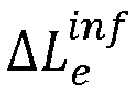
- In the following, steps S1 to S5 and S101 to S105 shown in
Fig. 2 will be described in detail. At first, a definition of the notation and variables used is given in the following table:Symbol Description Units c Speed of light m/s PRF Overall Pulse Repetition Frequency for all acquired channels Hz f0 Centre frequency Hz B System bandwidth, symmetric about f0 Hz PD Pulse Duration s RSF Range Sampling Frequency. Hz t, t' Pulse number (azimuth sample index) counting pulses in all data channels or only those in a particular channel, respectively τ, τ' Range sample index for the entire scene and relative to the expected range coordinate of a particular reference target, respectively 
A quantity derived from the response of reference target s in a channel that uses antenna elements p and q to transmit and receive signals, respectively. Dpq (t',τ) Raw measurement data acquired in channel pq Cpq (t',τ) Internal calibration data acquired for channel pq, obtained by recording pulses that have traversed the transmit- and receive-channels in the instrument. 
Range-compressed response of a reference target, corrected for expected systematic variations 
The range-compressed response 
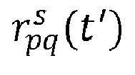
The expected two-way distance from the sensor to the target and back m 
Unit length line-of-sight vector from antenna element e to the reference target, in instrument coordinates m 
The expected two-way signal propagation time from the sensor to the target and back s 
The residual phase error for the reference target, after compensating for expected systematic variations rad 
The phase coherence of the reference target, which is close to 1 for a clean signal and decreases in the presence of noise 
The difference between the expected two-way propagation time 
s 
The difference between the expected and measured target RCS dB εopt A small, positive constant introduced for numerical stability during the minimisation of L1-norm errors. Set to 10-4 ΔCe (f) Complex, frequency dependent one-way response correction for antenna element e ΔAe Antenna element mount angle correction (roll,pitch,yaw) ΔLe Antenna element lever arm correction in instrument coordinates Δ c Global correction to the speed of light to account for tropospheric propagation delays ΔRCSe One-way antenna element gain calibration constant dB Δτe One-way antenna element delay calibration constant s Δφe One-way antenna element phase calibration constant rad - For a given acquisition, the navigation sub-system on the satellite provides a sensor position

- In addition, the navigation sub-system provides attitude angles

- The attitude angles measure the sensor roll (subscript r), pitch (subscript p) and yaw (subscript y) and relate the global (x,y,z) coordinate system to the so-called Cartesian instrument coordinate system. The latter has coordinate axes denoted (u,v,w) and is centred on the instrument reference point such that any particular point on the sensor has an instrument coordinate that is constant over time. Using these definitions, the time dependent transformation from instrument coordinates (u,v,w) to global coordinates (x,y,z) at a particular instant in time t can be defined as


- In addition, the calibration of element mount angles uses a modified inverse transformation

- in which an additional, constant roll, pitch and yaw correction ΔA is applied to the sensor attitude angles for the rotation from the instrument into the antenna element coordinate system.
- The SAR instrument (i.e. the radar sensor) under consideration uses an antenna array with E individual elements in an arbitrary spatial arrangement. In a polarimetric SAR sensor, each element may transmit and receive signals in horizontal (H) or vertical (V) polarisation. For the present purposes, the two modes of operation (H or V) are treated as two distinct elements, such that the E elements of the array actually correspond to E/2 physical elements with two polarisation settings each. The on-ground characterisation of the antenna array provides the following information concerning each particular element e of the array:
- Lever arm Le : The coordinates of the antenna phase centre as measured in the instrument coordinate system (u,v,w).
- Complex antenna gain diagram Ae (α, β, f): A diagram describing the amplification and phase shift affecting a signal transmitted or received through the antenna element in a particular propagation direction at a particular frequency. The three dimensions α, β and f denote the off-nadir angle, the squint angle and the frequency, respectively. The propagation direction, parameterised by angles α and β, is defined in terms of the instrument coordinate system. The propagation direction towards a point P measured relative to the element phase centre in the instrument coordinate system is given by the mappings


- The radar sensor provides multiple channels of complex SAR raw data Dpq (t',τ) as well as the corresponding internal calibration measurements Cpq (t',τ). The subscript pq identifies the data channel by the particular combination antenna array elements employed to transmit pulses (element p) and receive echoes (element q). In the present approach, SAR data acquired for calibration purposes always use individual antenna elements on transmit and receive, as the use of multiple elements would imply beam-forming, which in turn requires accurate array calibration to already have been carried out. The dimensions of the raw data are t', which is related to the discrete time t defined above, and τ, the so-called fast time, which measures the comparatively short duration between pulse transmission the time at which a particular raw data sample is received and recorded. In the following, t' and τ denote sample indices that can, however, be easily converted to physical units. The distinction between t and t' arises because, in practice, the particular transmit/receive element combination pq is interleaved with other combinations in a pulse sequence. Assuming a regular pulse sequence that repeats itself after L pulses results in the simple relationship

- Sensor calibration data takes are acquired over test-sites with dedicated reference targets. The relevant properties of these targets must be measured to a high degree of accuracy to allow for a meaningful comparison between the expected radar return and the actual SAR measurements. The relevant properties for a given reference target s are:
- Target Position Ts : Coordinates of the phase centre of the target in the global (x,y,z) coordinate system. The reference targets used are assumed to be very close to ideal point scatterers, such that the phase centre position remains constant as a function of illumination direction, frequency and polarisation.
- Target RCS


- The analysis of reference targets in the acquired calibration SAR data is the central building block of the calibration approach. The analysis comprises the selection and pre-processing of relevant parts of the input data and the subsequent extraction of information necessary for estimating calibration corrections. It is repeated for each valid reference target s in each SAR data channel pq acquired, where valid targets are those that can be expected to produce a response in the channel under consideration. Analysis does not, therefore, cover targets that are misaligned or do not produce a response for the transmit and receive antenna element polarisations in a particular SAR data channel.
- The process begins with pre-processing the navigation data. First, the position of transmit and receive phase centres for each pulse of the raw data channel in global coordinates are obtained from equations (3) and (8) as

- Given the phase centre positions, the following relevant spatial relationships between the sensor and the reference target during data acquisition are derived:


- It should be noted that, in contrast to other calibration corrections estimated, the tropospheric propagation correction Δ c is specific to the calibration acquisition under consideration and is not transferrable to other data takes. This is due to the fact that tropospheric conditions may change in time and, in the spaceborne case, the thickness of the troposphere between the reference target and the sensor changes depending on the altitude of the reference target (note that the form of the correction in eq. (14) assumes that all reference targets in a single calibration acquisition are at roughly the same altitude). The correction is nevertheless important, as it removes tropospheric bias from other corrections, such as the antenna lever arms and the residual range delays, which are then transferred to other data takes.
- The expected brightness of a given reference target in the SAR data acquired depends on the antenna element illumination in the direction of the target as a function of time as well as on the intrinsic brightness of the target.
- The time dependent antenna gain is obtained by first transforming the reference target position Ts into antenna element coordinates relative to the respective antenna element phase centre using the modified transform of equation (5):

- The time and frequency dependent two-way gain towards the reference target can then be obtained in using the mappings of equations (6) and (7)

- Similarly, the intrinsic brightness of the reference target as a function of frequency and time is obtained from the target RCS by applying equations (9) and (10) to the element phase centre positions in global coordinates:


- The radar returns of a single reference target in a single data channel occupy a small fraction of the total raw data constituting the calibration data acquisition. The first step of radar data analysis is therefore to determine the extent of the raw data to be analysed for a single target in a single channel. The aim of this section is to define a mask

- In azimuth, i.e. time t', the analysis limits must include at least those samples that cover the relevant portion of the antenna beam, i.e. the part that will be used in operational imaging modes. Mission planning is therefore expected to provide a mask


- The mask in range direction, Mrg (t',τ), includes the samples required for pulse compression (for a given pulse duration PD) at each azimuth time t' and a constant margin τmarg to account for residual range delays. It also accounts for internal delays within the radar instrument, δτpq (t').

- The instrument delay term is composed of the delay measurement that is part of the internal calibration data and an external calibration delay measurement.


- Once the relevant data limits are known, the corresponding data from the SAR raw data channel are read, compressed in range and corrected for known properties of the antenna element patterns, the expected reference target response, residual instrument delays and the propagation time from the antenna element phase centre to the target and back:


- In eq. (25), the mapping F[f] converts the frequency sample index f into a physical frequency measured in Hz, taking into account the centre frequency f0 and the range sampling frequency RSF.
- The calibration corrections ΔC e∈{p,q}(f) and Δτ e∈{p,q} denote residual corrections to the one-way frequency response and the one-way propagation delay of antenna elements p and q. They are initially 1 (for ΔC e∈{p,q}) and 0 (for Δτ e∈{p,q}) but take different values when reference target analysis is repeated later on in the calibration process.
- The application of eq. (23) has several simultaneous effects on the input raw data Dpq (t',τ):
- Range Compression: by effectively correlating the input raw data with the reference transfer function C.
- Amplitude Flattening: by removing systematic, azimuth and frequency dependent amplitude variations due to the antenna gain


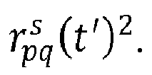
- Phase Flattening: by removing the expected phase variation due to the azimuth-variant propagation time from the sensor to the reference target and back as part of the phase correction φ. Importantly, this correction removes aliasing from the target response, such that analyses that follow are not biased by ambiguities, even when the input data are under-sampled in azimuth. Also note that frequency and propagation direction dependent variations of the antenna phase centre are compensated for by the phase of


- Range Cell Migration and Delay Correction: by including delay terms Δτ e∈{p,q} in the phase correction φ and making it frequency dependent.
- The output data

- The description in this section has, in the interest of clarity, not made reference to the sample mask of eq. (18). An actual implementation would use the mask to significantly increase computational efficiency by only processing the relevant samples for the data channel and reference target under consideration.
- The result of the radar raw data pre-processing is a data buffer

- The range compressed raw data

- Clutter filtering begins with a Fourier transformation in azimuth to obtain


- This transformation is essentially equivalent to performing an azimuth compression of the reference target response where, because the phase has been flattened in the application of eq. (23), ambiguities in the target response due to azimuth under-sampling of the raw data channel no longer occur. In

- Clutter suppression is achieved by damping energy contributions outside a small region around the compressed reference target using a Gaussian kernel K(faz ) to obtain the filtered data


- The Gaussian is centred about the maximum target response µ, determined within a range of permissible frequencies -fmax < faz < fmax :


- The standard deviation σ of the Gaussian filter is chosen to maximise clutter suppression while preserving features of the response down to the angular resolution in azimuth required for the accurate estimation of calibration corrections.
- The angular resolution is defined in terms of the effective squint angle

- The filter width then follows from the required angular resolution δβ, which is typically set to a value on the order of 0.1 degrees:

- Finally, accurate radiometric calibration requires an estimate of the clutter energy remaining in the reference target response after filtering. The average clutter energy per bin in the azimuth frequency domain is robustly estimated as the median intensity between two and three standard deviations offset from the peak response. The corresponding average clutter energy per sample in the azimuth time domain is then obtained by taking into account the kernel support as follows:

- Equation (33) assumes that the FFT and IFFT operations follow the generally accepted convention by using scaling factors of 1 and

- The amount of residual clutter energy is of central importance to the approach as a whole, as it quantifies the amount of noise that ultimately limits the accuracy of the calibration corrections derived. In this context, it should be pointed out that while the phase correction of eq. (25) ensures that azimuth under-sampling is not an issue for the reference target response itself, such under-sampling will increase the residual clutter energy due to aliased clutter contributions.
- The clutter filtered, range compressed raw data

- The residual phase measures phase errors in the target response that are related to inaccuracies in the navigation data and the antenna element lever arms.

- The target coherence is used to quantify the reliability of the measurement as a function of azimuth time. It is close to one for clean portions of the target response and decreases towards zero where the response is perturbed by residual clutter, system noise or radio frequency interference. It is denoted w, as it is principally used as a weight when deriving calibration corrections, and is defined as

- The residual delay measures the offset of the target response from the expected range at τ' = 0. It is estimated in a two-step procedure beginning with localising the maximum response with sample accuracy.

- A sub-sample refinement to the initial, coarse estimate is obtained by estimating a phase gradient in the frequency domain. Assuming that the filtered data has Nrg samples in the range dimension (corresponding to τ'), the residual target offset can be derived as



- The analysis of the filtered raw data with respect to the radar cross section aims to derive the absolute, unit-less offset, in dB, between the expected and the measured RCS of the reference target. Although equation (23) has already accounted for systematic intensity variations due to antenna element gains and the expected target RCS, the derivation of the absolute RCS offset from the filtered data must also include additional terms from the radar equation for real-aperture radar and compensate for the residual clutter intensity of eq. (33) as follows:

- The aim of the residual range impulse response calibration is to measure systematic, frequency dependent amplitude and non-linear phase variations that occur within the pulse bandwidth when internal calibration measurements fail to faithfully reproduce the transfer function of the radar instrument. Corresponding corrections are estimated for each individual antenna element and are assumed to be reciprocal, i.e. identical on transmit and receive.
- Estimation begins with pre-processing the filtered raw data to remove constant offsets in gain, residual delay, phase and amplitude as follows:


- Corrections in terms of gain, in dB, and phase are estimated separately. Each antenna element e is thereby associated with corrections


- The error functions defined above use the L1-norm, rather than quadratic errors, to reduce the impact of outliers on the solution. The L1-error minimisation is carried out using an iteratively re-weighted least squares approach applied to linear equations of the form


- Given a set of current correction estimates


- Upon convergence, the complex valued response correction for an antenna element e is given by

- After residual range frequency response corrections have been obtained, the reference target analysis of section § 1 is repeated, where these corrections are taken into account in eq. (24), before further calibration corrections are derived.
- The aim of the element mount angle estimation is to derive optimal roll/pitch/yaw corrections


- As before, the optimisation uses a L1-error function to reduce the impact of outliers and needs to be carried by iteratively solving re-weighted least-squares problems. The minimisation of errors of the form (49) is complicated, however, by the non-linearity of eq. (51) in terms of attitude corrections ΔAe . The first step is therefore to derive a linear approximation of


- The local gradients


- The determination of antenna element mount angles is then carried out as a fixed point iteration. Each iteration solves an over-determined system of equations of the form

- The iteration accomplishes the robust L1-norm minimisation implied by the form of the error function in eq. (49) by updating the weights


- The iteration terminates once the antenna element mount angles have converged. The reference target analysis described in section § 1 is then repeated, where the estimated mount angle corrections are taken into account in eq. (16), before proceeding with further calibration steps.
- For polarimetric SAR sensors, the above procedure must be modified to ensure that a single physical antenna element is associated with only one mount angle, instead of separate mount angles for the H and V polarisations. This is achieved by simply reducing the number of unknowns by symbolically setting

- The positions of the antenna element phase centres, as parameterised by the corresponding lever arms, are refined in two steps. The first step, described in this section, derives relatively coarse positions that are accurate to within the limits set by residual errors affecting the input navigation data and the assumed reference target positions. This coarse estimate also accounts for a residual tropospheric propagation delay, modelled as a correction to the speed of light.
- The optimisation process uses two error functions that essentially separate the effects of element lever arm related errors into the range and azimuth dimensions. The first error function relates the lever arm corrections to the measured range position offsets of reference targets:


- This error function aims to explain the observed reference target range offsets


- The impact of residual element lever arm errors and the tropospheric propagation delay as a function of azimuth time t' is captured by a second error function based on the residual phase


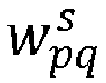
- The azimuth error function is similar to that of eq. (55) and penalises residual phase variations that can be reduced by introducing appropriate lever arm and tropospheric propagation corrections. The variable

- As before, the error functions use the L1-norm instead of quadratic penalties to reduce the impact of outliers on the optimisation. The error minimisation can therefore be formulated as an iterated least-squares process applied to an over-determined system of equations of the form


- Once the iteration has converged, for instance when the maximum lever arm change falls to a small fraction of the radar wavelength, the estimated range shifts Δre can be converted into one-way antenna element propagation delays using the estimated Δ c via

- Finally, the reference target analysis of section § 1 is carried out anew for all data channels and reference targets to ensure that the updated calibration corrections are taken into account before proceeding further. In addition, for very large lever arm corrections that cause a measurable change in the line-of-sight vectors

- A further refinement of the antenna element phase centre position is possible using interferograms between filtered, range-compressed raw data channels derived for the same reference target. In contrast to the coarse estimate attained in section § 4, the refined estimate is independent of residual errors in the navigation data and the reference target positions. The two approaches are complementary in that the interferometric approach cannot determine absolute phase centre positions or accurately characterise tropospheric propagation effects. Instead, it yields highly accurate estimates of the spatial separation, or baseline, between antenna element phase centres.
- The residual interferometric phase between two data channels pq and uv corresponding to the same reference target s is obtained as

- Analysis begins by grouping phase vectors


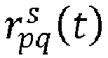


- The error model used for baseline refinement can be stated as



- The robust L1-norm minimisation of errors


- The system of equations would be singular without these additional constraints. They imply that interferometric baseline optimisation introduces corrections to the antenna element phase centre positions that conserve the geometric centre of the antenna array in the instrument coordinate system.
- Upon convergence, when changes to


- Following the update, a final iteration of reference target analysis, using the updated element lever arms, is carried out to ensure a consistent basis for estimating calibration constants as described in the next section.
- Once the antenna array is considered well calibrated, it is possible to estimate calibration constants, at the level of the individual antenna array element, to ensure that the SAR imagery obtained after image formation can be directly related to physical parameters of the imaged scene. The corrections concern the one-way delay, gain and phase shift affecting signals upon propagation through a given antenna element, and are, for the most part, already estimated as by-products of optimisations in the preceding sections. To eliminate possible bias arising from the interplay of calibration corrections and the sequence in which they are estimated, the final set of calibration constants is re-derived as follows:
- The element gain ΔRCSe is obtained by iteratively minimising eq. (49), keeping element mount angles ΔAe fixed at their previously determined values.
- The element delay Δτe is obtained by iteratively minimising eq. (55), keeping element lever arm corrections ΔLe and the tropospheric propagation correction Δc fixed at their previously determined values, and applying eq. (62).
- The phase calibration constants Δφpq,uv do not need to be re-estimated, as they are the product of the last calibration correction. These constants are, however, not specific to individual antenna elements but to a particular data channel combination, such that a post-processing step is required to derive per-element corrections. This step solves a system of equations of the form

- 1. Initialise any one of the calibration constants Δφe to an arbitrary value
- 2. Identify an interferometric channel combination pq,uv in which three of the four antenna elements involved have already been associated with phase calibration constants.
- 3. Solve the following equation for the remaining unknown phase calibration constant by straight-forward re-arrangement:

- 4. Continue at step 2 until all antenna elements have been associated with phase calibration constants.
- The constraint on the data channels made available for calibration is that the condition in step 2 must be fulfilled in each iteration. Having initialised a single Δφe in step 1, it implies that the calibration data set includes channels corresponding to antenna element combinations ee and eq for the derivation of Δφq via Δφee,eq. After two elements are associated with phase calibration constants, there is an increasing amount of freedom in the channel combinations sufficient for calibration.
- It should be noted that the arbitrary initialisation does not have any impact on the sensor calibration in the sense that the choice of initial value has no impact on any conceivable interferometric measurement the sensor can carry out.
- The process outlined for element-wise phase correction derives each calibration constant from a single interferometric measurement Δφpq,uv , such that many of the possible interferometric channel combinations are never, in fact, used. This is sub-optimal in terms of measurement noise affecting the estimates Δφpq,uv. The phase calibration is therefore refined in a second processing step that begins with determining the wrapping numbers on the basis of the initial values of Δφe :

- The element-wise calibration of an antenna array as outlined in sections § 2 to § 5 has implicitly assumed that at least one array element can both transmit and receive signals. For sensors that employ disjoint transmit and receive antenna arrays, in which each element either transmits or receives, this is not the case and the estimation of calibration corrections fails due to the fact that the systems of equations proposed become singular.
- To extend the calibration approach to these types of SAR sensors, it is necessary to further constrain the optimisation by performing, symbolically, the following substitutions for a single, arbitrarily chosen antenna element e:





- The antenna element mount angles ΔAe are not affected, provided that the transmit and receive elements have different antenna illumination diagrams.
- In addition, the initialisation of the iterative algorithm for the element-wise phase calibration of the array in section § 6 must be adjusted: instead of initialising a single phase calibration constant Δφe in step 1, it is necessary to initialise two constants Δφu and Δφv , where u and v correspond to one transmit and one receive antenna element.
- While the quality of the resulting calibration is not impaired for this type of sensor, the element-wise calibration corrections no longer have an absolute meaning: only differences between the calibration corrections for individual array elements can be meaningfully analysed.
- Multistatic SAR involves the joint analysis and processing of radar data acquired by a formation of independent SAR sensors. If each SAR sensor in the formation can both receive and transmit signals, each can be calibrated as a monostatic system using the approaches described. Should this not be the case, however, the entire formation must be jointly calibrated.
- In doing so, the proposed approach is affected only in that each sensor provides its own navigation data N(t) of eq. (1) and attitudes A(t) of eq. (2). The reference target analysis of section § 1 must therefore ensure that the underlying geometric transforms in equations (3), (4) and (5) are based on the navigation data appropriate for the particular antenna element under consideration. The remainder of the calibration approach is unaffected.
- The invention as described in the foregoing has several advantages. It provides an accurate calibration of multi-channel SAR instruments, such as those required to support SAR polarimetry, single-pass interferometry and digital beam-forming, on the basis of dedicated SAR acquisitions containing reference targets with known properties.
- Unlike conventional approaches, the method is based on the analysis of range compressed raw data. It does not require SAR image focussing in azimuth, which is essential in cases where azimuth focussing requires beam-forming techniques and thus presupposes an accurate calibration of the antenna array.
- The method assumes that the internal calibration sub-system of the sensor is able to effectively compensate for transient drifts due to propagation effects within the radar instrument. The focus is, instead, on providing an accurate and consistent characterisation of the antenna array, which is, by definition, outside the scope of internal calibration techniques. The approach introduces an explicit model of possible calibration error sources and uses SAR measurements to derive corresponding corrections. The error sources considered, for each antenna element in an array, are as follows:
- 1. Element mount angles: these describe a mispointing of the antenna element in terms of the attitude angles pitch, yaw and roll. Accurate determination of mount angles enables accurate radiometric calibration of SAR imagery in arbitrary imaging geometries. Non-zero mount angles occur due to alignment errors during the on-ground characterisation of antenna element illumination patterns, due to angular tilts of the antenna upon deployment and/or due to attitude offsets in the data provided by the navigation subsystem of the instrument.
- 2. Element baselines: The relative separation between element phase centres. Accurate knowledge of baselines is essential for multi-channel SAR sensors, as even small baseline errors translate to phase errors that distort interferometric and polarimetric SAR measurements as well as the effective antenna illumination pattern when beam-forming is employed. Although the separation of phase centres can be derived from phase measurements of the element patterns on ground, residual errors arise when such measurements are simply not available or unreliable, or when baselines change upon deployment, e.g. due to panel tilts or the absence of gravitational distortions of the antenna array that have impacted the on-ground characterisation.
- 3. Absolute array position: A reference point that, in conjunction with the element baselines, determines the absolute position of element phase centres in 3D space. Errors in the absolute array position translate into geo-location errors in the focussed SAR image. This type of error may arise due to imperfections in the deployment of the antenna array or systematic errors in the positioning information provided by the navigation sub-system of the instrument.
- 4. Residual impulse response errors: These are frequency dependent, incremental corrections to the characterisation of the radar instrument's transfer function provided by internal calibration measurements. These corrections account for amplitude and non-linear phase variations within the pulse bandwidth and are assumed to be stable over time and independent of propagation direction in three dimensional space.
- 5. Calibration constants: Constant corrections in terms of intensity, delay and phase can be derived once other corrections have been taken into account. These constants are introduced to ensure the absolute calibration of the SAR instrument and ensure that SAR imagery can be related to physical properties of the imaged scene in terms of backscatter intensity, geo-location and inter-channel phase differences.
- 6. Residual errors: Frequency and propagation direction dependent amplitude and phase errors that remain after all corrections have been taken into account serve to validate the error model used and point to remaining calibration issues. The detailed characterisation of unexpected residual errors helps to identify possible causes and formulate mitigation strategies. As an example, residual errors may include the propagation direction dependent effects introduced by antenna array element coupling that could not be adequately modelled or characterised on ground.
- The results of the analyses carried out for each point in the above list serve the dual purpose of validation. They provide a granular picture of the calibration corrections required that can then be assessed with respect to prior expectations to pinpoint issues related to the on-ground characterisation process, the internal calibration and navigation sub-systems and the sensor deployment process. Regular calibration data takes enable detailed monitoring of the instrument stability, especially with respect to the performance of the antenna array, and the introduction of additional corrections when and if they become necessary.
- The proposed calibration technique as described herein is fundamentally different to existing approaches in that it is based on the analysis of the response of reference targets in range compressed raw data. Conventional external calibration approaches, by contrast, use focussed SAR imagery, while data-driven approaches that are based on range compressed SAR data do not take advantage of reference targets. The following description highlights specific, unique characteristics of the proposed approach that largely stem from this fundamental difference. The names of particular processing steps are typeset in bold and refer to the flowcharts of
Fig. 2 . - The pre-processing of SAR raw data includes a Response Correction that, among other things, removes aliasing from the reference target response of each individual data channel without resorting to beam-forming techniques. Existing calibration techniques do not apply to sub-sampled data or use beam-forming techniques that are problematic when applied before the antenna array is fully calibrated. Pre-processing also includes a novel filtering operation for Clutter Suppression, in which the response of the reference target is cleanly separated out by suppressing backscatter contributions from other parts of the imaged scene.
- The Residual Error Analysis, carried out on the pre-processed raw data, identifies residual deviations from the expected reference target response in terms of range position, phase and backscatter intensity. In contrast to conventional external calibration approaches, which analyse reference targets in focussed SAR imagery, this analysis captures variations within the illumination time, i.e. along azimuth. In particular, the analysis yields the target radar cross section (RCS) as measured by each received echo in the radar raw data by applying the radar equation for real aperture radar.
- The Residual Range IRF analysis uses a robust (L1-Norm minimisation) algorithm for estimating residual, radar frequency-dependent amplitude and phase variations. This optimisation algorithm explicitly takes into account the frequency response measured in each echo received from reference targets and has not been used in this context before. The approach makes the estimates derived more robust with respect to outliers caused by residual clutter and radio frequency interference.
- The Element Mount Angles estimation introduces pointing corrections that minimise the observed RCS deviations, taking into account the sensor attitude angles and possible variations thereof during the illumination time. Other calibration approaches do not include such mount angles at all, such that both the error model used and the estimation algorithm can be considered novel.
- The approach includes a two-step refinement of antenna element phase centre positions. The first step, Element Lever Arms, provides coarse corrections that minimise the observed range position discrepancies and phase errors along azimuth (I.e. during the illumination time). The underlying error model and the estimation algorithm differ from existing approaches in that:
- The combination of input measurements used is unique, in that conventional external calibration approaches do not take into account azimuth-variant phase discrepancies while data-driven approaches cannot take into account range position discrepancies.
- The error model explicitly includes tropospheric propagation effects, which are not considered by existing calibration approaches.
- The error model explicitly takes into account the sensor attitude angles and possible variations thereof during the illumination time. Existing calibration approaches do not take into account sensor attitudes.
- The approach provides 3D position corrections. Other calibration techniques are restricted to one or two dimensions or do not provide an explicit estimate at all (e.g. some data-driven approaches merely carry out a phase correction without explicitly estimating position errors).
- In a subsequent refinement step, highly accurate estimates of the Element Baselines are obtained by minimising interferometric phase errors. The approach differs from existing techniques by taking into account interferometric phase variations within the illumination time and sensor attitude angles and providing 3D baseline error estimates.
- Finally, the estimation of Calibration Constants is achieved by robust L1-Norm optimisation, which has not been used in this context before. In addition, it includes an iterative algorithm for estimating element-wise phase calibration constants from wrapped interferometric phase measurements. This novel algorithm could also be applied in the context of conventional external calibration approaches.
- In the foregoing, an embodiment of the invention has been described including calibration procedures S2 to S4 in combination with reference target analyses TA1 to TA4. However, the invention may also be implemented by only performing a sub-set of those calibration procedures. Furthermore, the calibration procedure according to step S1 is optional and may be omitted in specific embodiments of the invention.
- Analogously, step S5, referring to the determination of calibration constants, may be omitted in specific embodiments of the invention. Moreover, steps S101 to S05 of the reference target analysis may be implemented in a different way as long as target data for each channel and each reference target are extracted appropriately. Particularly, the clutter suppression of step S104 may be omitted in case that the SAR raw data comprise little or no clutter.
Claims (15)
- A method for computer-assisted processing of SAR raw data (Dpq), comprising radar echoes from ground that are the response to radar pulses (RP) that have been transmitted by antenna elements (101, 102, 103) of a radar sensor (1) on at least one flying object (SA) moving in an azimuth direction (x) above ground and where the radar echoes have been received by antenna elements (101, 102, 103) of the radar sensor (1), the SAR raw data (Dpq) including radar echoes originating from reference targets (RT) with known radar cross sections and positions on ground and being represented by data acquisitions for several channels (pq), each channel (pq) referring to radar pulses transmitted by a specific antenna element (101, 102, 103) and radar echoes received by a specific antenna element (101, 102, 103), where the data acquisition for a channel (pq) comprises a plurality of data samples for several azimuth positions and several range positions, the range positions corresponding to different distances from the radar sensor (1) to ground,
characterised in that the method comprises one or more calibration procedures (TA2, S2; TA3, S3; TA4, S4), each calibration procedure comprising the following steps:i) by using the known radar cross section and position on ground for each reference target (RT), extracting target data (Fs pq) for each reference target (RT) in each channel (pq) from the SAR raw data (Dpq) and determining a variation of one or more measurements (δφs pq, δRCSs pq, δφs pq,uv) over different radar echoes originating from each reference target (RT) for each channel (pq) or for each combination of two channels (pq) based on the target data (Fs pq);ii) determining one or more calibration factors in the form of one or more correction terms (ΔAe, ΔLe, ΔLe inf) for one or more sensor parameters of the radar sensor (1) based on an optimisation comprising the optimisation goal to minimise the variation of the one or more measurements (δφs pq, δRCSs pq, δφs pq,uv) for all reference targets (RT) and for all channels (pq) or all combinations of two channels (pq). - The method according to claim 1, characterised in that the one or more calibration procedures (TA2, S2; TA3, S3; TA4, S4) comprise a first calibration procedure (TA2, S2) wherein the variation of a measurement determined in step i) refers to the variation of a radar cross section offset (δRCSs pq) over different radar echoes originating from each reference target (RT) in each channel (pq) and wherein correction terms (ΔAe) for sensor parameters in the form of antenna mount angles of each antenna element (101, 102, 103) on the at least one flying object (1) are determined in step ii), where the radar cross section offset (δRCSs pq) represents the difference between the known radar cross section and the radar cross section according to the target data (Fs pq) for the respective reference target (RT) and the respective channel (pq) .
- The method according to claim 1 or 2, characterised in that the one or more calibration procedures (TA2, S2; TA3, S3; TA4, S4) comprise a second calibration procedure (TA3, S3) wherein the variation of a measurement determined in step i) refers to the variation of a residual phase (δφs pq) over different radar echoes originating from each reference target (RT) in each channel (pq) and wherein correction terms (ΔLe) for sensor parameters in the form of relative positions of the phase centres of the antenna elements (101, 102, 103) with respect to a reference position on the at least one flying object (1) are determined in step ii), where the residual phase (δφs pq) for a respective channel (pq) represents the difference between the phase of a radar echo based on the positions of the transmitting and receiving antenna element phase centres of the respective channel (pq) and based on the known position of the respective reference target (RT) on ground on the one hand and the phase according to the target data for the respective reference target (RT) on the other hand, where preferably the optimisation within the second calibration procedure (TA3, S3) includes the additional optimisation goal to minimise the mean residual delay (δτs pq) over different radar echoes originating from each reference target (RT) in each channel (pq), where the residual delay (δτs pq) for a respective channel (pq) represents the difference between the propagation time from transmitting a radar pulse until receiving its radar echo based on the positions of the transmitting and receiving antenna element phase centres of the respective channel (pq) and based on the known position of the respective reference target (RT) on ground on the one hand and the corresponding propagation time according to the target data for the respective reference target (RT) on the other hand.
- The method according to one of the preceding claims, characterised in that the one or more calibration procedures (TA2, S2; TA3, S3; TA4, S4) comprise a third calibration procedure (TA4, S4) wherein the variation of a measurement determined in step i) refers to the variation of the difference (δφs pq,uv) between two residual phases for two channels (pq) over different radar echoes originating from each reference target (RT) in each combination of two channels (pq) and wherein correction terms (ΔLe inf) for sensor parameters in the form of relative positions of the phase centres of the antenna elements (101, 102, 103) with respect to a reference position on the at least one flying object (1) are determined in step ii), where the residual phase (δφs pq) for a respective channel (pq) represents the difference between the phase of a radar echo based on the positions of the transmitting and receiving antenna element phase centres of the respective channel (pq) and based on the known position of the respective reference target (RT) on ground on the one hand and the phase according to the target data for the respective reference target (RT) on the other hand.
- The method according to claims 2 to 4, characterised in that the method comprises the first and the second and the third calibration procedures (TA2, S2; TA3, S3; TA4, S4), where preferably the third calibration procedure is performed after the second calibration procedure and the second calibration procedure is performed after the first calibration procedure.
- The method according to one of the preceding claims, characterised in that the method comprises several calibration procedures (TA2, S2; TA3, S3; TA4, S4) which are performed based on an iteration, where each calibration procedure constitutes an iteration step and where step i) of an iteration step takes into account one or more calibration factors determined in all preceding iteration steps.
- The method according to one of the preceding claims, characterised in that the extraction of target data (Fs pq) for each reference target (RT) and each channel (pq) in step i) of at least one calibration procedure comprises a range compression and a correction based on the known radar cross section and the known position of the respective reference target (RT) on ground.
- The method according to one of the preceding claims, characterised in that the extraction of target data (Fs pq) for each reference target (RT) and each channel (pq) in step i) of at least one calibration procedure comprises a clutter suppression for suppressing radar echoes originating from scatterers other than the respective reference target (RT).
- The method according to one of the preceding claims, characterised in that the method comprises a separate calibration procedure (TA1, S1) in addition to the one or more calibration procedures (TA2, S2; TA3, S3; TA4, S4), where the separate calibration procedure (TA1, S1) comprises the following steps:a) by using the known radar cross section and position on ground for each reference target (RT), extracting target data (Fs pq) for each reference target (RT) in each channel (pq) from the SAR raw data (Dpq) and determining the variation of a residual delay (δτs pq) over different radar echoes originating from each reference target (RT) in each channel (pq), where the residual delay (δτs pq) for a respective channel (pq) represents the difference between the propagation time from transmitting a radar pulse until receiving its radar echo based on the positions of the transmitting and receiving antenna element phase centres of the respective channel (pq) and based on the known position of the respective reference target (RT) on ground on the one hand and the corresponding propagation time according to the target data for the respective reference target (RT) on the other hand;b) estimating frequency-dependent phase and amplitude variations within the bandwidth of the radar echoes by determining calibration factors in the form of correction terms (ΔCe) for the respective antenna elements (101, 102, 103) based on a minimisation of error functions, where at least one error function is defined over different radar echoes originating from each reference target (RT) in each channel (pq), the at least one error function being defined based on a frequency response function for each radar echo originating from the respective reference target (RT) in the respective channel (pq), where the frequency response function is derived from the target data (Fs pq) and the variation of the residual delay (δτs pq) obtained in step a).
- The method according to claim 9 in combination with claim 6, characterised in that the separate calibration procedure (TA1, S1) is part of the iteration and forms an iteration step therein, where step i) of all iteration steps after the iteration step of the separate calibration procedure (TA1, S1) takes into account the calibration factors determined in step b).
- The method according to one of the preceding claims, characterized in that, after performing the one or more calibration procedures, one or more calibration constants (ΔRCSe, Δτe, Δφ e) are determined, any of which (ΔRCSe, Δτe, Δφ e) provided to be applied in a later processing of other SAR raw data as overall, constant corrections to the entire SAR raw data sor entire images derived from the SAR raw data.
- An apparatus for computer-assisted processing of SAR raw data (Dpq), comprising radar echoes from ground that are the response to radar pulses (RP) that have been transmitted by antenna elements (101, 102, 103) of a radar sensor (1) on at least one flying object (SA) moving in an azimuth direction (x) above ground and where the radar echoes have been received by antenna elements (101, 102, 103) of the radar sensor (1), the SAR raw data (Dpq) including radar echoes originating from reference targets (RT) with known radar cross sections and positions on ground and being represented by data acquisitions for several channels (pq), each channel (pq) referring to radar pulses transmitted by a specific antenna element (101, 102, 103) and radar echoes received by a specific antenna element (101, 102, 103), where the data acquisition for a channel (pq) comprises a plurality of data samples for several azimuth positions and several range positions, the range positions the range positions corresponding to different distances from the radar sensor (1) to ground,,
characterised in that the apparatus is configured to perform a method comprising one or more calibration procedures (TA2, S2; TA3, S3; TA4, S4), each calibration procedure comprising the following steps:i) by using the known radar cross section and position on ground for each reference target (RT), extracting target data (Fs pq) for each reference target (RT) in each channel (pq) from the SAR raw data (Dpq) and determining a variation of one or more measurements (δφs pq, δRCSs pq, δφs pq,uv) within a set of radar echoes originating from each reference target (RT) for each channel (pq) or for each combination of two channels (pq) based on the target data (Fs pq);ii) determining one or more calibration factors in the form of one or more correction terms (ΔAe, ΔLe, ΔLe inf) for one or more sensor parameters of the radar sensor (1) based on an optimisation comprising the optimisation goal to minimise the variation of the one or more measurements (δφs pq, δRCSs pq, δφs pq,uv) for all reference targets (RT) and for all channels (pq) or all combinations of two channels (pq). - The apparatus according to claim 12, characterised in that the apparatus is configured to perform a method according to one of claims 2 to 11.
- A computer program product comprising program code stored on a machine readable medium, characterised in that the program code is configured to perform a method according to one of claims 1 to 11, when the program code is run on a computer.
- A computer program comprising program code, characterised in that the program code is configured to perform a method according to one of claims 1 to 11, when the program code is run on a computer.
Priority Applications (1)
| Application Number | Priority Date | Filing Date | Title |
|---|---|---|---|
| EP17156196.2A EP3364212B1 (en) | 2017-02-15 | 2017-02-15 | A method and an apparatus for computer-assisted processing of sar raw data |
Applications Claiming Priority (1)
| Application Number | Priority Date | Filing Date | Title |
|---|---|---|---|
| EP17156196.2A EP3364212B1 (en) | 2017-02-15 | 2017-02-15 | A method and an apparatus for computer-assisted processing of sar raw data |
Publications (3)
| Publication Number | Publication Date |
|---|---|
| EP3364212A1 true EP3364212A1 (en) | 2018-08-22 |
| EP3364212B1 EP3364212B1 (en) | 2025-08-27 |
| EP3364212C0 EP3364212C0 (en) | 2025-08-27 |
Family
ID=58046556
Family Applications (1)
| Application Number | Title | Priority Date | Filing Date |
|---|---|---|---|
| EP17156196.2A Active EP3364212B1 (en) | 2017-02-15 | 2017-02-15 | A method and an apparatus for computer-assisted processing of sar raw data |
Country Status (1)
| Country | Link |
|---|---|
| EP (1) | EP3364212B1 (en) |
Cited By (49)
| Publication number | Priority date | Publication date | Assignee | Title |
|---|---|---|---|---|
| CN109459736A (en) * | 2019-01-04 | 2019-03-12 | 北京环境特性研究所 | A kind of radar drone design method and apparatus |
| CN110146858A (en) * | 2019-05-24 | 2019-08-20 | 北京航空航天大学 | A high-precision full-link spaceborne SAR radiation calibration simulation method |
| CN110146859A (en) * | 2019-05-30 | 2019-08-20 | 中国人民解放军63921部队 | A kind of method and apparatus for radar cross section RCS calibration |
| CN110412378A (en) * | 2019-07-30 | 2019-11-05 | 北京经纬恒润科技有限公司 | Target object detection method and device |
| CN111580053A (en) * | 2020-05-30 | 2020-08-25 | 中国人民解放军海军航空大学 | Joint calculation and correction method of measurement error of time-varying radar scattering center of large ship target |
| CN111708017A (en) * | 2020-05-27 | 2020-09-25 | 中国电子科技集团公司信息科学研究院 | A multi-radar joint detection method and device based on Gaussian kernel |
| CN111766580A (en) * | 2020-07-10 | 2020-10-13 | 中国科学院空天信息创新研究院 | The method of successive recursive refinement of ground position of SAR remote sensing satellite big data |
| CN111861230A (en) * | 2020-07-24 | 2020-10-30 | 二十一世纪空间技术应用股份有限公司 | A multi-satellite collaborative observation mission planning method and device for disaster emergency |
| CN111856415A (en) * | 2020-06-19 | 2020-10-30 | 中国电子科技集团公司第二十七研究所 | A method, device and storage medium for advance calibration of radar data processing equipment |
| US20200363500A1 (en) * | 2019-05-13 | 2020-11-19 | Gm Cruise Holdings Llc | Radar cross section compensation for calibration of vehicle radar |
| CN112068086A (en) * | 2020-10-17 | 2020-12-11 | 中国电波传播研究所(中国电子科技集团公司第二十二研究所) | An Amplitude and Phase Correction Method for Shore-based Multi-channel Radar Based on External Calibration Test Data |
| CN112180370A (en) * | 2020-09-29 | 2021-01-05 | 中国科学院空天信息创新研究院 | A SAR range reference signal processing method and device |
| US10895637B1 (en) * | 2019-07-17 | 2021-01-19 | BGA Technology LLC | Systems and methods for mapping manmade objects buried in subterranean surfaces using an unmanned aerial vehicle integrated with radar sensor equipment |
| CN112286165A (en) * | 2020-09-30 | 2021-01-29 | 上海艾为电子技术股份有限公司 | Method for calibrating drive waveform data of linear motor and electronic device |
| CN112305526A (en) * | 2020-10-22 | 2021-02-02 | 电子科技大学 | Distributed array system synchronization method based on external calibration source |
| CN112462339A (en) * | 2020-09-29 | 2021-03-09 | 北京空间飞行器总体设计部 | Three-order Doppler parameter calculation method for geosynchronous orbit SAR (synthetic Aperture Radar) satellite |
| CN112816969A (en) * | 2020-12-30 | 2021-05-18 | 西安电子科技大学 | External radiation source radar data real-time transmission method and system based on balanced buffer area |
| CN113093190A (en) * | 2021-04-08 | 2021-07-09 | 中国电子科技集团公司第三十八研究所 | Airborne strip SAR image positioning method based on high-precision combined inertial navigation system |
| CN113126051A (en) * | 2021-03-05 | 2021-07-16 | 西安电子科技大学 | Airborne multi-channel SAR interference effective baseline estimation method and device |
| CN113176573A (en) * | 2021-04-23 | 2021-07-27 | 哈尔滨工业大学 | Complex domain structured SAR ship target dynamic simulation and speed estimation method |
| CN114885036A (en) * | 2022-07-12 | 2022-08-09 | 深圳安德空间技术有限公司 | Real-time lossy compression method and system for ground penetrating radar data |
| CN115421112A (en) * | 2022-09-02 | 2022-12-02 | 惠州市德赛西威智能交通技术研究院有限公司 | Self-calibration method and calibration system for vehicle-mounted radar, vehicle-mounted radar and automobile |
| US20230105684A1 (en) * | 2021-10-01 | 2023-04-06 | Gm Cruise Holdings Llc | System and method for end of line test and calibration of angular scanning radar |
| EP4231052A1 (en) * | 2022-02-18 | 2023-08-23 | Fraunhofer-Gesellschaft zur Förderung der angewandten Forschung e.V. | Device and method for calibrating at least one parameter of a radar system, and mobile radar system |
| CN117741269A (en) * | 2023-12-11 | 2024-03-22 | 中国电子科技集团公司第三十八研究所 | Phase center calibration method for large-scale broadband conformal digital array |
| US12058333B1 (en) * | 2023-12-12 | 2024-08-06 | AtomBeam Technologies Inc. | System and methods for upsampling of decompressed data after lossy compression using a neural network |
| CN118604758A (en) * | 2024-06-17 | 2024-09-06 | 中国科学技术大学 | Millimeter wave radar calibration method and application based on natural point target search |
| CN119012340A (en) * | 2023-05-19 | 2024-11-22 | 中国移动通信有限公司研究院 | Information processing method, device, equipment and readable storage medium |
| US12199644B1 (en) | 2023-12-12 | 2025-01-14 | Atombeam Technologies Inc | System and method for homomorphic compression using latent space preprocessing and neural upsampling |
| DE102023121355A1 (en) | 2023-08-10 | 2025-02-13 | Deutsches Zentrum für Luft- und Raumfahrt e.V. | Method for calibrating the antenna alignment of a SAR sensor |
| WO2025031859A1 (en) | 2023-08-10 | 2025-02-13 | Deutsches Zentrum für Luft- und Raumfahrt e.V. | Method for calibrating an sar sensor |
| US12231151B1 (en) | 2017-10-30 | 2025-02-18 | Atombeam Technologies Inc | Federated large codeword model deep learning architecture with homomorphic compression and encryption |
| US12261631B2 (en) | 2017-10-30 | 2025-03-25 | Atombeam Technologies Inc | Deep learning using large codeword model with homomorphically compressed data |
| CN119846627A (en) * | 2025-01-13 | 2025-04-18 | 启元实验室 | On-orbit radiation and geometric correction method for satellite-borne SAR image based on parallel computing architecture |
| US12294640B1 (en) | 2023-12-12 | 2025-05-06 | Atombeam Technologies Inc | System and method for distributed edge-cloud homomorphic compression using adaptive neural networks |
| CN119984116A (en) * | 2025-04-17 | 2025-05-13 | 应急管理部国家自然灾害防治研究院 | Open-pit slope deformation monitoring method and system based on radar collaboration |
| US12379486B2 (en) * | 2021-12-15 | 2025-08-05 | Korea Aerospace Research Institute | Method of calculating power level reflectance of object on ground using SAR image |
| US12469179B2 (en) | 2023-12-12 | 2025-11-11 | AtomBeam Technologies Inc. | System and methods for upsampling of decompressed data after lossy compression using a neural network |
| US12493569B2 (en) | 2023-12-12 | 2025-12-09 | AtomBeam Technologies Inc. | System and method for energy-aware distributed edge-cloud homomorphic compression using adaptive neural networks |
| US12506496B2 (en) | 2024-05-23 | 2025-12-23 | AtomBeam Technologies Inc. | Hierarchical smart caching for machine learning codeword responses |
| US12572830B1 (en) | 2024-05-23 | 2026-03-10 | AtomBeam Technologies Inc. | System and method for enterprise hierarchical persistent cognitive machines with organizational hierarchy awareness and compliance integration |
| US12579437B2 (en) | 2024-05-23 | 2026-03-17 | AtomBeam Technologies Inc. | Mobile-optimized multi-stage LLM with federated persistent cognitive architecture |
| US12602586B2 (en) | 2024-05-23 | 2026-04-14 | Atombeam Technolgies Inc. | Supervisory neuron for continuously adaptive neural network |
| US12626167B2 (en) | 2024-05-23 | 2026-05-12 | AtomBeam Technologies Inc. | System and method for large language model with integrated memory during inference using manifold traversal architecture |
| US12627315B2 (en) | 2024-05-23 | 2026-05-12 | AtomBeam Technologies Inc. | Latent transformer architecture with attention mechanisms and expert systems for federated deep learning with homomorphic encryption |
| US12664440B2 (en) | 2024-05-23 | 2026-06-23 | AtomBeam Technologies Inc. | System and method for a large codeword model for deep learning |
| CN122315346A (en) * | 2026-05-29 | 2026-06-30 | 江苏亨鑫科技有限公司 | An antenna angle calibration device and its usage method |
| US12682176B2 (en) | 2023-12-12 | 2026-07-14 | AtomBeam Technologies Inc. | System and method for real-time team intent modeling using persistent cognitive machines with federated human profiles |
| CN122315346B (en) * | 2026-05-29 | 2026-08-14 | 江苏亨鑫科技有限公司 | An antenna angle calibration device and its usage method |
Citations (1)
| Publication number | Priority date | Publication date | Assignee | Title |
|---|---|---|---|---|
| US20080150793A1 (en) * | 2004-02-27 | 2008-06-26 | Daniel Christopher Bast | Pulse-Coded Remote Calibration of an Active Phased Array System |
-
2017
- 2017-02-15 EP EP17156196.2A patent/EP3364212B1/en active Active
Patent Citations (1)
| Publication number | Priority date | Publication date | Assignee | Title |
|---|---|---|---|---|
| US20080150793A1 (en) * | 2004-02-27 | 2008-06-26 | Daniel Christopher Bast | Pulse-Coded Remote Calibration of an Active Phased Array System |
Non-Patent Citations (5)
| Title |
|---|
| DALE C GRIFFITH: "Phase Error Compensation Technique for Improved Synthetic Aperture Radar Performance", JOHNS HOPKINS APL TECHNICAL DIGEST, vol. 18, no. 3, 1 January 1997 (1997-01-01), pages 358 - 364, XP055383275 * |
| FREEMAN A: "SAR CALIBRATION: AN OVERVIEW", IEEE TRANSACTIONS ON GEOSCIENCE AND REMOTE SENSING, IEEE SERVICE CENTER, PISCATAWAY, NJ, US, vol. 30, no. 6, 1 November 1992 (1992-11-01), pages 1107 - 1121, XP000336641, ISSN: 0196-2892, DOI: 10.1109/36.193786 * |
| GRAY A L ET AL: "SYNTHETIC APERTURE RADAR CALIBRATION USING REFERENCE REFLECTORS", IEEE TRANSACTIONS ON GEOSCIENCE AND REMOTE SENSING, IEEE SERVICE CENTER, PISCATAWAY, NJ, US, vol. 28, no. 3, 1 May 1990 (1990-05-01), pages 374 - 382, XP000128243, ISSN: 0196-2892, DOI: 10.1109/36.54363 * |
| PAU PRATS-IRAOLA ET AL: "High precision SAR focusing of TerraSAR-X experimental staring spotlight data", GEOSCIENCE AND REMOTE SENSING SYMPOSIUM (IGARSS), 2012 IEEE INTERNATIONAL, IEEE, 22 July 2012 (2012-07-22), pages 3576 - 3579, XP032468576, ISBN: 978-1-4673-1160-1, DOI: 10.1109/IGARSS.2012.6350644 * |
| PING WEN JIANG ET AL: "External caubration of the CRS-1 satellite", COMPUTATIONAL ELECTROMAGNETICS AND ITS APPLICATIONS, 2004. PROCEEDINGS . ICCEA 2004. 2004 3RD INTERNATIONAL CONFERENCE ON BEIJING, CHINA NOV. 1-4, 2004, PISCATAWAY, NJ, USA,IEEE, 1 November 2004 (2004-11-01), pages 395 - 398, XP010812101, ISBN: 978-0-7803-8562-7, DOI: 10.1109/ICCEA.2004.1459375 * |
Cited By (73)
| Publication number | Priority date | Publication date | Assignee | Title |
|---|---|---|---|---|
| US12261631B2 (en) | 2017-10-30 | 2025-03-25 | Atombeam Technologies Inc | Deep learning using large codeword model with homomorphically compressed data |
| US12231151B1 (en) | 2017-10-30 | 2025-02-18 | Atombeam Technologies Inc | Federated large codeword model deep learning architecture with homomorphic compression and encryption |
| CN109459736A (en) * | 2019-01-04 | 2019-03-12 | 北京环境特性研究所 | A kind of radar drone design method and apparatus |
| US20200363500A1 (en) * | 2019-05-13 | 2020-11-19 | Gm Cruise Holdings Llc | Radar cross section compensation for calibration of vehicle radar |
| US11754672B2 (en) * | 2019-05-13 | 2023-09-12 | Gm Cruise Holdings Llc | RADAR cross section compensation for calibration of vehicle RADAR |
| CN110146858A (en) * | 2019-05-24 | 2019-08-20 | 北京航空航天大学 | A high-precision full-link spaceborne SAR radiation calibration simulation method |
| CN110146859A (en) * | 2019-05-30 | 2019-08-20 | 中国人民解放军63921部队 | A kind of method and apparatus for radar cross section RCS calibration |
| US20210096240A1 (en) * | 2019-07-17 | 2021-04-01 | BGA Technology LLC | Systems and methods for mapping manmade objects buried in subterranean surfaces using an unmanned aerial vehicle integrated with radar sensor equipment |
| US11714189B2 (en) * | 2019-07-17 | 2023-08-01 | BGA Technology LLC | Systems and methods for mapping manmade objects buried in subterranean surfaces using an unmanned aerial vehicle integrated with radar sensor equipment |
| US10895637B1 (en) * | 2019-07-17 | 2021-01-19 | BGA Technology LLC | Systems and methods for mapping manmade objects buried in subterranean surfaces using an unmanned aerial vehicle integrated with radar sensor equipment |
| CN110412378A (en) * | 2019-07-30 | 2019-11-05 | 北京经纬恒润科技有限公司 | Target object detection method and device |
| CN110412378B (en) * | 2019-07-30 | 2021-08-24 | 北京经纬恒润科技股份有限公司 | Target object detection method and device |
| CN111708017A (en) * | 2020-05-27 | 2020-09-25 | 中国电子科技集团公司信息科学研究院 | A multi-radar joint detection method and device based on Gaussian kernel |
| CN111708017B (en) * | 2020-05-27 | 2023-07-07 | 中国电子科技集团公司信息科学研究院 | A multi-radar joint detection method and device based on Gaussian kernel |
| CN111580053A (en) * | 2020-05-30 | 2020-08-25 | 中国人民解放军海军航空大学 | Joint calculation and correction method of measurement error of time-varying radar scattering center of large ship target |
| CN111856415A (en) * | 2020-06-19 | 2020-10-30 | 中国电子科技集团公司第二十七研究所 | A method, device and storage medium for advance calibration of radar data processing equipment |
| CN111766580B (en) * | 2020-07-10 | 2022-03-11 | 中国科学院空天信息创新研究院 | The method of successive recursive refinement of ground position of SAR remote sensing satellite big data |
| CN111766580A (en) * | 2020-07-10 | 2020-10-13 | 中国科学院空天信息创新研究院 | The method of successive recursive refinement of ground position of SAR remote sensing satellite big data |
| CN111861230A (en) * | 2020-07-24 | 2020-10-30 | 二十一世纪空间技术应用股份有限公司 | A multi-satellite collaborative observation mission planning method and device for disaster emergency |
| CN111861230B (en) * | 2020-07-24 | 2023-11-28 | 二十一世纪空间技术应用股份有限公司 | A multi-satellite collaborative observation mission planning method and device for disaster emergency |
| CN112462339A (en) * | 2020-09-29 | 2021-03-09 | 北京空间飞行器总体设计部 | Three-order Doppler parameter calculation method for geosynchronous orbit SAR (synthetic Aperture Radar) satellite |
| CN112180370A (en) * | 2020-09-29 | 2021-01-05 | 中国科学院空天信息创新研究院 | A SAR range reference signal processing method and device |
| CN112462339B (en) * | 2020-09-29 | 2023-07-25 | 北京空间飞行器总体设计部 | A Calculation Method of Third-Order Doppler Parameters for Geosynchronous Orbit SAR Satellites |
| CN112180370B (en) * | 2020-09-29 | 2023-07-25 | 中国科学院空天信息创新研究院 | SAR range reference signal processing method and device |
| CN112286165A (en) * | 2020-09-30 | 2021-01-29 | 上海艾为电子技术股份有限公司 | Method for calibrating drive waveform data of linear motor and electronic device |
| CN112068086B (en) * | 2020-10-17 | 2022-03-01 | 中国电波传播研究所(中国电子科技集团公司第二十二研究所) | An Amplitude and Phase Correction Method for Shore-Based Multi-channel Radar Based on External Calibration Test Data |
| CN112068086A (en) * | 2020-10-17 | 2020-12-11 | 中国电波传播研究所(中国电子科技集团公司第二十二研究所) | An Amplitude and Phase Correction Method for Shore-based Multi-channel Radar Based on External Calibration Test Data |
| CN112305526A (en) * | 2020-10-22 | 2021-02-02 | 电子科技大学 | Distributed array system synchronization method based on external calibration source |
| CN112305526B (en) * | 2020-10-22 | 2023-05-26 | 电子科技大学 | Distributed array system synchronization method based on external calibration source |
| CN112816969A (en) * | 2020-12-30 | 2021-05-18 | 西安电子科技大学 | External radiation source radar data real-time transmission method and system based on balanced buffer area |
| CN112816969B (en) * | 2020-12-30 | 2023-12-22 | 西安电子科技大学 | Real-time transmission method and system of external radiation source radar data based on equalization buffer zone |
| CN113126051A (en) * | 2021-03-05 | 2021-07-16 | 西安电子科技大学 | Airborne multi-channel SAR interference effective baseline estimation method and device |
| CN113126051B (en) * | 2021-03-05 | 2023-09-19 | 西安电子科技大学 | An effective baseline estimation method and device for airborne multi-channel SAR interference |
| CN113093190A (en) * | 2021-04-08 | 2021-07-09 | 中国电子科技集团公司第三十八研究所 | Airborne strip SAR image positioning method based on high-precision combined inertial navigation system |
| CN113176573A (en) * | 2021-04-23 | 2021-07-27 | 哈尔滨工业大学 | Complex domain structured SAR ship target dynamic simulation and speed estimation method |
| US12498455B2 (en) * | 2021-10-01 | 2025-12-16 | Gm Cruise Holdings Llc | System and method for end of line test and calibration of angular scanning radar |
| US20230105684A1 (en) * | 2021-10-01 | 2023-04-06 | Gm Cruise Holdings Llc | System and method for end of line test and calibration of angular scanning radar |
| US12379486B2 (en) * | 2021-12-15 | 2025-08-05 | Korea Aerospace Research Institute | Method of calculating power level reflectance of object on ground using SAR image |
| EP4231052A1 (en) * | 2022-02-18 | 2023-08-23 | Fraunhofer-Gesellschaft zur Förderung der angewandten Forschung e.V. | Device and method for calibrating at least one parameter of a radar system, and mobile radar system |
| DE102022103958A1 (en) | 2022-02-18 | 2023-08-24 | Fraunhofer-Gesellschaft zur Förderung der angewandten Forschung eingetragener Verein | Device and method for calibrating at least one parameter of a radar system and mobile radar system |
| CN114885036B (en) * | 2022-07-12 | 2022-09-23 | 深圳安德空间技术有限公司 | Real-time lossy compression method and system for ground penetrating radar data |
| CN114885036A (en) * | 2022-07-12 | 2022-08-09 | 深圳安德空间技术有限公司 | Real-time lossy compression method and system for ground penetrating radar data |
| CN115421112A (en) * | 2022-09-02 | 2022-12-02 | 惠州市德赛西威智能交通技术研究院有限公司 | Self-calibration method and calibration system for vehicle-mounted radar, vehicle-mounted radar and automobile |
| CN115421112B (en) * | 2022-09-02 | 2024-12-17 | 惠州市德赛西威智能交通技术研究院有限公司 | Vehicle-mounted radar self-calibration method, calibration system, vehicle-mounted radar and automobile |
| CN119012340A (en) * | 2023-05-19 | 2024-11-22 | 中国移动通信有限公司研究院 | Information processing method, device, equipment and readable storage medium |
| DE102023121355A1 (en) | 2023-08-10 | 2025-02-13 | Deutsches Zentrum für Luft- und Raumfahrt e.V. | Method for calibrating the antenna alignment of a SAR sensor |
| WO2025031875A1 (en) | 2023-08-10 | 2025-02-13 | Deutsches Zentrum für Luft- und Raumfahrt e.V. | Method for calibrating the antenna alignment of an sar sensor |
| WO2025031859A1 (en) | 2023-08-10 | 2025-02-13 | Deutsches Zentrum für Luft- und Raumfahrt e.V. | Method for calibrating an sar sensor |
| DE102023121354A1 (en) | 2023-08-10 | 2025-02-13 | Deutsches Zentrum für Luft- und Raumfahrt e.V. | Procedure for calibrating a SAR sensor |
| DE102023121354B4 (en) * | 2023-08-10 | 2025-09-25 | Deutsches Zentrum für Luft- und Raumfahrt e.V. | Procedure for calibrating a SAR sensor |
| DE102023121355B4 (en) * | 2023-08-10 | 2025-10-09 | Deutsches Zentrum für Luft- und Raumfahrt e.V. | Procedure for calibrating the antenna orientation of a SAR sensor |
| CN117741269A (en) * | 2023-12-11 | 2024-03-22 | 中国电子科技集团公司第三十八研究所 | Phase center calibration method for large-scale broadband conformal digital array |
| US12294640B1 (en) | 2023-12-12 | 2025-05-06 | Atombeam Technologies Inc | System and method for distributed edge-cloud homomorphic compression using adaptive neural networks |
| US12058333B1 (en) * | 2023-12-12 | 2024-08-06 | AtomBeam Technologies Inc. | System and methods for upsampling of decompressed data after lossy compression using a neural network |
| US12701235B2 (en) | 2023-12-12 | 2026-08-04 | AtomBeam Technologies Inc. | System and methods for upsampling of decompressed data after lossy compression using a neural network |
| US12199644B1 (en) | 2023-12-12 | 2025-01-14 | Atombeam Technologies Inc | System and method for homomorphic compression using latent space preprocessing and neural upsampling |
| US12682176B2 (en) | 2023-12-12 | 2026-07-14 | AtomBeam Technologies Inc. | System and method for real-time team intent modeling using persistent cognitive machines with federated human profiles |
| US12469179B2 (en) | 2023-12-12 | 2025-11-11 | AtomBeam Technologies Inc. | System and methods for upsampling of decompressed data after lossy compression using a neural network |
| US12477117B2 (en) | 2023-12-12 | 2025-11-18 | AtomBeam Technologies Inc. | System and methods for upsampling of decompressed data after lossy compression using a neural network |
| US12493569B2 (en) | 2023-12-12 | 2025-12-09 | AtomBeam Technologies Inc. | System and method for energy-aware distributed edge-cloud homomorphic compression using adaptive neural networks |
| US12579437B2 (en) | 2024-05-23 | 2026-03-17 | AtomBeam Technologies Inc. | Mobile-optimized multi-stage LLM with federated persistent cognitive architecture |
| US12506496B2 (en) | 2024-05-23 | 2025-12-23 | AtomBeam Technologies Inc. | Hierarchical smart caching for machine learning codeword responses |
| US12572830B1 (en) | 2024-05-23 | 2026-03-10 | AtomBeam Technologies Inc. | System and method for enterprise hierarchical persistent cognitive machines with organizational hierarchy awareness and compliance integration |
| US12602586B2 (en) | 2024-05-23 | 2026-04-14 | Atombeam Technolgies Inc. | Supervisory neuron for continuously adaptive neural network |
| US12626167B2 (en) | 2024-05-23 | 2026-05-12 | AtomBeam Technologies Inc. | System and method for large language model with integrated memory during inference using manifold traversal architecture |
| US12627315B2 (en) | 2024-05-23 | 2026-05-12 | AtomBeam Technologies Inc. | Latent transformer architecture with attention mechanisms and expert systems for federated deep learning with homomorphic encryption |
| US12664440B2 (en) | 2024-05-23 | 2026-06-23 | AtomBeam Technologies Inc. | System and method for a large codeword model for deep learning |
| CN118604758A (en) * | 2024-06-17 | 2024-09-06 | 中国科学技术大学 | Millimeter wave radar calibration method and application based on natural point target search |
| CN119846627A (en) * | 2025-01-13 | 2025-04-18 | 启元实验室 | On-orbit radiation and geometric correction method for satellite-borne SAR image based on parallel computing architecture |
| CN119984116A (en) * | 2025-04-17 | 2025-05-13 | 应急管理部国家自然灾害防治研究院 | Open-pit slope deformation monitoring method and system based on radar collaboration |
| US12712706B2 (en) | 2025-04-24 | 2026-08-18 | AtomBeam Technologies Inc. | Adaptive video compression with enhanced data restoration |
| CN122315346A (en) * | 2026-05-29 | 2026-06-30 | 江苏亨鑫科技有限公司 | An antenna angle calibration device and its usage method |
| CN122315346B (en) * | 2026-05-29 | 2026-08-14 | 江苏亨鑫科技有限公司 | An antenna angle calibration device and its usage method |
Also Published As
| Publication number | Publication date |
|---|---|
| EP3364212B1 (en) | 2025-08-27 |
| EP3364212C0 (en) | 2025-08-27 |
Similar Documents
| Publication | Publication Date | Title |
|---|---|---|
| EP3364212B1 (en) | A method and an apparatus for computer-assisted processing of sar raw data | |
| Fornaro et al. | Motion compensation errors: Effects on the accuracy of airborne SAR images | |
| De Macedo et al. | An autofocus approach for residual motion errors with application to airborne repeat-pass SAR interferometry | |
| CN108627831B (en) | An ISAR imaging method for ultra-low signal-to-noise ratio medium and high orbit satellite targets | |
| US4924229A (en) | Phase correction system for automatic focusing of synthetic aperture radar | |
| Rabus et al. | The shuttle radar topography mission—a new class of digital elevation models acquired by spaceborne radar | |
| CN110865346B (en) | Satellite-borne SAR time parameter calibration method based on direct positioning algorithm | |
| JP6660857B2 (en) | Method of generating image of region of interest using radar system | |
| CN106526593B (en) | Sub-pixel-level corner reflector automatic positioning method based on the tight imaging model of SAR | |
| CN102645651A (en) | A SAR tomographic super-resolution imaging method | |
| Pu et al. | A rise-dimensional modeling and estimation method for flight trajectory error in bistatic forward-looking SAR | |
| CN112986949B (en) | SAR high-precision time sequence deformation monitoring method and device for diagonal reflector | |
| CN115685203B (en) | A multi-channel radar forward-looking super-resolution imaging method | |
| CN113238225A (en) | Radar for moving target detection | |
| CN111551934A (en) | Motion compensation self-focusing method and device for unmanned aerial vehicle SAR imaging | |
| CN112711021B (en) | Multi-resolution InSAR (interferometric synthetic Aperture Radar) interactive interference time sequence analysis method | |
| CN104062657A (en) | Generalized polar coordinate imaging method for synthetic aperture radar (SAR) | |
| Gisinger et al. | Differential geodetic stereo SAR with TerraSAR-X by exploiting small multi-directional radar reflectors | |
| RU2661941C1 (en) | Method for radar imaging using the radar station with the synthesized aperture | |
| Gong et al. | High resolution 3D InISAR imaging of space targets based on PFA algorithm with single baseline | |
| CN117665809A (en) | Inversion method for forest canopy height | |
| Farhadi et al. | Synthetic aperture radar imaging of moving targets for automotive applications | |
| CN121784737A (en) | High-precision deformation monitoring and target imaging method based on MIMO-SAR | |
| CN113406632A (en) | L-band spaceborne bistatic SAR signal processing method and device and storage medium | |
| Ma et al. | System error analysis and calibration methods for multi-channel SAR |
Legal Events
| Date | Code | Title | Description |
|---|---|---|---|
| PUAI | Public reference made under article 153(3) epc to a published international application that has entered the european phase |
Free format text: ORIGINAL CODE: 0009012 |
|
| STAA | Information on the status of an ep patent application or granted ep patent |
Free format text: STATUS: THE APPLICATION HAS BEEN PUBLISHED |
|
| AK | Designated contracting states |
Kind code of ref document: A1 Designated state(s): AL AT BE BG CH CY CZ DE DK EE ES FI FR GB GR HR HU IE IS IT LI LT LU LV MC MK MT NL NO PL PT RO RS SE SI SK SM TR |
|
| AX | Request for extension of the european patent |
Extension state: BA ME |
|
| STAA | Information on the status of an ep patent application or granted ep patent |
Free format text: STATUS: REQUEST FOR EXAMINATION WAS MADE |
|
| 17P | Request for examination filed |
Effective date: 20190118 |
|
| RBV | Designated contracting states (corrected) |
Designated state(s): AL AT BE BG CH CY CZ DE DK EE ES FI FR GB GR HR HU IE IS IT LI LT LU LV MC MK MT NL NO PL PT RO RS SE SI SK SM TR |
|
| STAA | Information on the status of an ep patent application or granted ep patent |
Free format text: STATUS: EXAMINATION IS IN PROGRESS |
|
| 17Q | First examination report despatched |
Effective date: 20210223 |
|
| GRAP | Despatch of communication of intention to grant a patent |
Free format text: ORIGINAL CODE: EPIDOSNIGR1 |
|
| STAA | Information on the status of an ep patent application or granted ep patent |
Free format text: STATUS: GRANT OF PATENT IS INTENDED |
|
| INTG | Intention to grant announced |
Effective date: 20250425 |
|
| GRAS | Grant fee paid |
Free format text: ORIGINAL CODE: EPIDOSNIGR3 |
|
| GRAA | (expected) grant |
Free format text: ORIGINAL CODE: 0009210 |
|
| STAA | Information on the status of an ep patent application or granted ep patent |
Free format text: STATUS: THE PATENT HAS BEEN GRANTED |
|
| AK | Designated contracting states |
Kind code of ref document: B1 Designated state(s): AL AT BE BG CH CY CZ DE DK EE ES FI FR GB GR HR HU IE IS IT LI LT LU LV MC MK MT NL NO PL PT RO RS SE SI SK SM TR |
|
| REG | Reference to a national code |
Ref country code: GB Ref legal event code: FG4D |
|
| REG | Reference to a national code |
Ref country code: CH Ref legal event code: EP |
|
| REG | Reference to a national code |
Ref country code: DE Ref legal event code: R096 Ref document number: 602017091416 Country of ref document: DE |
|
| REG | Reference to a national code |
Ref country code: IE Ref legal event code: FG4D |
|
| U01 | Request for unitary effect filed |
Effective date: 20250905 |
|
| U07 | Unitary effect registered |
Designated state(s): AT BE BG DE DK EE FI FR IT LT LU LV MT NL PT RO SE SI Effective date: 20250912 |
|
| PG25 | Lapsed in a contracting state [announced via postgrant information from national office to epo] |
Ref country code: IS Free format text: LAPSE BECAUSE OF FAILURE TO SUBMIT A TRANSLATION OF THE DESCRIPTION OR TO PAY THE FEE WITHIN THE PRESCRIBED TIME-LIMIT Effective date: 20251227 |
|
| PG25 | Lapsed in a contracting state [announced via postgrant information from national office to epo] |
Ref country code: NO Free format text: LAPSE BECAUSE OF FAILURE TO SUBMIT A TRANSLATION OF THE DESCRIPTION OR TO PAY THE FEE WITHIN THE PRESCRIBED TIME-LIMIT Effective date: 20251127 |
|
| PG25 | Lapsed in a contracting state [announced via postgrant information from national office to epo] |
Ref country code: HR Free format text: LAPSE BECAUSE OF FAILURE TO SUBMIT A TRANSLATION OF THE DESCRIPTION OR TO PAY THE FEE WITHIN THE PRESCRIBED TIME-LIMIT Effective date: 20250827 |
|
| PG25 | Lapsed in a contracting state [announced via postgrant information from national office to epo] |
Ref country code: GR Free format text: LAPSE BECAUSE OF FAILURE TO SUBMIT A TRANSLATION OF THE DESCRIPTION OR TO PAY THE FEE WITHIN THE PRESCRIBED TIME-LIMIT Effective date: 20251128 |
|
| PG25 | Lapsed in a contracting state [announced via postgrant information from national office to epo] |
Ref country code: PL Free format text: LAPSE BECAUSE OF FAILURE TO SUBMIT A TRANSLATION OF THE DESCRIPTION OR TO PAY THE FEE WITHIN THE PRESCRIBED TIME-LIMIT Effective date: 20250827 |
|
| PG25 | Lapsed in a contracting state [announced via postgrant information from national office to epo] |
Ref country code: RS Free format text: LAPSE BECAUSE OF FAILURE TO SUBMIT A TRANSLATION OF THE DESCRIPTION OR TO PAY THE FEE WITHIN THE PRESCRIBED TIME-LIMIT Effective date: 20251127 |
|
| PG25 | Lapsed in a contracting state [announced via postgrant information from national office to epo] |
Ref country code: ES Free format text: LAPSE BECAUSE OF FAILURE TO SUBMIT A TRANSLATION OF THE DESCRIPTION OR TO PAY THE FEE WITHIN THE PRESCRIBED TIME-LIMIT Effective date: 20250827 |
|
| U20 | Renewal fee for the european patent with unitary effect paid |
Year of fee payment: 10 Effective date: 20260112 |
|
| PG25 | Lapsed in a contracting state [announced via postgrant information from national office to epo] |
Ref country code: SM Free format text: LAPSE BECAUSE OF FAILURE TO SUBMIT A TRANSLATION OF THE DESCRIPTION OR TO PAY THE FEE WITHIN THE PRESCRIBED TIME-LIMIT Effective date: 20250827 |
|
| PG25 | Lapsed in a contracting state [announced via postgrant information from national office to epo] |
Ref country code: CZ Free format text: LAPSE BECAUSE OF FAILURE TO SUBMIT A TRANSLATION OF THE DESCRIPTION OR TO PAY THE FEE WITHIN THE PRESCRIBED TIME-LIMIT Effective date: 20250827 |
|
| PG25 | Lapsed in a contracting state [announced via postgrant information from national office to epo] |
Ref country code: SK Free format text: LAPSE BECAUSE OF FAILURE TO SUBMIT A TRANSLATION OF THE DESCRIPTION OR TO PAY THE FEE WITHIN THE PRESCRIBED TIME-LIMIT Effective date: 20250827 |
|
| PLBE | No opposition filed within time limit |
Free format text: ORIGINAL CODE: 0009261 |
|
| STAA | Information on the status of an ep patent application or granted ep patent |
Free format text: STATUS: NO OPPOSITION FILED WITHIN TIME LIMIT |
|
| REG | Reference to a national code |
Ref country code: CH Ref legal event code: L10 Free format text: ST27 STATUS EVENT CODE: U-0-0-L10-L00 (AS PROVIDED BY THE NATIONAL OFFICE) Effective date: 20260708 |
|
| 26N | No opposition filed |
Effective date: 20260528 |