EP3364211A1 - Method and device for detecting a possible collision, and vehicle - Google Patents
Method and device for detecting a possible collision, and vehicle Download PDFInfo
- Publication number
- EP3364211A1 EP3364211A1 EP17465504.3A EP17465504A EP3364211A1 EP 3364211 A1 EP3364211 A1 EP 3364211A1 EP 17465504 A EP17465504 A EP 17465504A EP 3364211 A1 EP3364211 A1 EP 3364211A1
- Authority
- EP
- European Patent Office
- Prior art keywords
- vehicle
- collision
- trajectory
- time
- approximated
- Prior art date
- Legal status (The legal status is an assumption and is not a legal conclusion. Google has not performed a legal analysis and makes no representation as to the accuracy of the status listed.)
- Granted
Links
Images



Classifications
-
- G—PHYSICS
- G01—MEASURING; TESTING
- G01S—RADIO DIRECTION-FINDING; RADIO NAVIGATION; DETERMINING DISTANCE OR VELOCITY BY USE OF RADIO WAVES; LOCATING OR PRESENCE-DETECTING BY USE OF THE REFLECTION OR RERADIATION OF RADIO WAVES; ANALOGOUS ARRANGEMENTS USING OTHER WAVES
- G01S13/00—Systems using the reflection or reradiation of radio waves, e.g. radar systems; Analogous systems using reflection or reradiation of waves whose nature or wavelength is irrelevant or unspecified
- G01S13/88—Radar or analogous systems specially adapted for specific applications
- G01S13/93—Radar or analogous systems specially adapted for specific applications for anti-collision purposes
- G01S13/931—Radar or analogous systems specially adapted for specific applications for anti-collision purposes of land vehicles
-
- B—PERFORMING OPERATIONS; TRANSPORTING
- B60—VEHICLES IN GENERAL
- B60W—CONJOINT CONTROL OF VEHICLE SUB-UNITS OF DIFFERENT TYPE OR DIFFERENT FUNCTION; CONTROL SYSTEMS SPECIALLY ADAPTED FOR HYBRID VEHICLES; ROAD VEHICLE DRIVE CONTROL SYSTEMS FOR PURPOSES NOT RELATED TO THE CONTROL OF A PARTICULAR SUB-UNIT
- B60W30/00—Purposes of road vehicle drive control systems not related to the control of a particular sub-unit, e.g. of systems using conjoint control of vehicle sub-units
- B60W30/08—Active safety systems predicting or avoiding probable or impending collision or attempting to minimise its consequences
- B60W30/095—Predicting travel path or likelihood of collision
-
- G—PHYSICS
- G01—MEASURING; TESTING
- G01S—RADIO DIRECTION-FINDING; RADIO NAVIGATION; DETERMINING DISTANCE OR VELOCITY BY USE OF RADIO WAVES; LOCATING OR PRESENCE-DETECTING BY USE OF THE REFLECTION OR RERADIATION OF RADIO WAVES; ANALOGOUS ARRANGEMENTS USING OTHER WAVES
- G01S13/00—Systems using the reflection or reradiation of radio waves, e.g. radar systems; Analogous systems using reflection or reradiation of waves whose nature or wavelength is irrelevant or unspecified
- G01S13/66—Radar-tracking systems; Analogous systems
- G01S13/72—Radar-tracking systems; Analogous systems for two-dimensional [2D] tracking, e.g. combination of angle and range tracking, track-while-scan radar
- G01S13/723—Radar-tracking systems; Analogous systems for two-dimensional [2D] tracking, e.g. combination of angle and range tracking, track-while-scan radar by using numerical data
-
- G—PHYSICS
- G01—MEASURING; TESTING
- G01S—RADIO DIRECTION-FINDING; RADIO NAVIGATION; DETERMINING DISTANCE OR VELOCITY BY USE OF RADIO WAVES; LOCATING OR PRESENCE-DETECTING BY USE OF THE REFLECTION OR RERADIATION OF RADIO WAVES; ANALOGOUS ARRANGEMENTS USING OTHER WAVES
- G01S13/00—Systems using the reflection or reradiation of radio waves, e.g. radar systems; Analogous systems using reflection or reradiation of waves whose nature or wavelength is irrelevant or unspecified
- G01S13/88—Radar or analogous systems specially adapted for specific applications
- G01S13/93—Radar or analogous systems specially adapted for specific applications for anti-collision purposes
- G01S13/931—Radar or analogous systems specially adapted for specific applications for anti-collision purposes of land vehicles
- G01S2013/932—Radar or analogous systems specially adapted for specific applications for anti-collision purposes of land vehicles using own vehicle data, e.g. ground speed, steering wheel direction
-
- G—PHYSICS
- G01—MEASURING; TESTING
- G01S—RADIO DIRECTION-FINDING; RADIO NAVIGATION; DETERMINING DISTANCE OR VELOCITY BY USE OF RADIO WAVES; LOCATING OR PRESENCE-DETECTING BY USE OF THE REFLECTION OR RERADIATION OF RADIO WAVES; ANALOGOUS ARRANGEMENTS USING OTHER WAVES
- G01S13/00—Systems using the reflection or reradiation of radio waves, e.g. radar systems; Analogous systems using reflection or reradiation of waves whose nature or wavelength is irrelevant or unspecified
- G01S13/88—Radar or analogous systems specially adapted for specific applications
- G01S13/93—Radar or analogous systems specially adapted for specific applications for anti-collision purposes
- G01S13/931—Radar or analogous systems specially adapted for specific applications for anti-collision purposes of land vehicles
- G01S2013/9327—Sensor installation details
- G01S2013/93271—Sensor installation details in the front of the vehicles
Definitions
- the invention relates to a method and a device for detecting a possible collision of a vehicle with a moving object.
- the invention further relates to a vehicle.
- a method for detecting a possible collision of a vehicle with a moving object as recited in claim 1 is provided.
- the invention further provides a device for detecting a possible collision of a vehicle with a moving object as recited in claim 11. Further, a vehicle as recited in claim 14 is provided.
- the invention therefore provides a method for detecting a possible collision of a vehicle with a moving object. Spatial positions of the object are determined for a series of time points based on sensor data obtained by the vehicle. An approximated trajectory of the object is constructed by approximating the spatial positions of the object. A possible collision of the vehicle with the object is predicted based on the approximated trajectory of the object and/or based on a time dependence of the approximated trajectory of the object.
- a device for detecting a possible collision of a vehicle with a moving object which comprises an interface and an evaluation unit.
- the interface is adapted to receive sensor data obtained by the vehicle.
- the evaluation unit is adapted to determine spatial positions of the object for a series of time points based on the received sensor data.
- the evaluation unit is further adapted to construct an approximated trajectory of the object by approximating the spatial positions of the object.
- the evaluation unit further predicts a possible collision of the vehicle with the object based on the approximated trajectory of the object and/or based on a time dependence of the approximated trajectory of the object.
- the invention provides a vehicle comprising a sensor system adapted to provide sensor data of a surrounding of the vehicle, and a device for predicting a possible collision of the vehicle with a moving object based on the provided sensor data.
- the spatial positions of the object i.e., the exact absolute coordinates of the object, are used in order to determine the course or trajectory of the object. Therefore, the movement of the object is detected over a certain period of time which helps to improve predicting the future location of the object relative to the vehicle. In this way, a possible collision can be determined with a higher precision.
- the moving object can for example be a further vehicle, a motorcycle or a pedestrian.
- a possible collision of the vehicle with the object is predicted based on a curvature of the approximated trajectory of the object.
- the prediction of the possible collision can depend on a specific situation. For example, it may be detected that the vehicle drives towards a roundabout.
- the curvature can be used to determine if the moving object is exiting the roundabout, stays in the roundabout, or is heading towards the vehicle. For example, if the curvature is zero or if the absolute value of the curvature is smaller than a predetermined value, the object is moving essentially along a straight line. In this case, the object will eventually cross the trajectory of the vehicle and a collision is predicted. On the other hand, if the absolute value of the curvature is larger than a predetermined value, no collision is predicted. Depending on the sign of the curvature, it is determined that the object is either exiting the roundabout or is staying in the roundabout.
- the approximated trajectory is constructed by computing smoothed positions by smoothing the spatial positions of the object, and by constructing the approximated trajectory as an interpolated curve for the smoothed positions using De Boor's algorithm.
- smoothing the spatial position is performed using a Savitzky-Golay filter.
- the approximated trajectory is constructed using polynomial regression.
- the approximated trajectory can be constructed by fitting a third order polynomial.
- the approximated trajectory is constructed as a regression line through the spatial positions.
- a possible collision of the vehicle with the objects is predicted based on the time-dependence of a slope of the regression line. Accordingly, it is determined how the slope changes over time in order to find out if the object is moving straight ahead or if the object is moving along a bent curve.
- a time to collision is determined based on the sensor data, wherein the time to collision is modified based on the approximated trajectory and/or based on the time dependence of the approximated trajectory. For example, depending on how likely a collision of the vehicle with the object is, based on the approximated trajectory and/or based on the time dependence of the approximated trajectory, the time to collision is adjusted accordingly. Therefore, the invention helps to prevent unnecessary breaking maneuvers which could occur due to wrong predictions based on the sensor data.
- modifying the time to collision comprises multiplying the time to collision by an exponential factor involving a curvature of the approximated trajectory, if the curvature of the approximated trajectory lies within a predetermined interval.
- the predetermined interval may also depend on a specific situation. For example, if the vehicle is driving towards a roundabout and the object is identified within the roundabout, the time to collision may be reduced if the absolute value of the curvature is larger than a predetermined value. In such a case, the vehicle is exiting the roundabout or stays within the roundabout and there is no collision danger. In contrast, if the absolute value of the curvature is smaller than a predetermined value, the time to collision is left unchanged because the object moving is driving straight and a collision with the vehicle is likely.
- a probability for a collision of the vehicle with a moving object is computed based on the approximated trajectory and/or based on a time dependence of the approximated trajectory.
- the probability may depend on the absolute value of the curvature of the approximated trajectory.
- a movement of the vehicle is controlled if a possible collision of the vehicle with the object has been predicted.
- the vehicle may be slowed down or the vehicle may be steered away from the trajectory of the object.
- the evaluation unit is adapted to construct the approximated trajectory using polynomial regression.
- the evaluation unit is further adapted to determine a time to collision based on the sensor data and is adapted to modify the time to collision based on the approximated trajectory.
- the vehicle comprises a control unit which is adapted to control a movement of the vehicle if a possible collision of the vehicle with an object has been predicted.
- Figure 1 shows a block diagram of a device 1 for detecting a possible collision of a vehicle V with a moving object O.
- a possible scenario is illustrated in figure 2 , where the vehicle V is driving towards a junction and the object O is another vehicle which is turning from the crossing road into the road of the vehicle V.
- the device 1 comprises an interface 2 which is adapted to receive sensor data obtained by the vehicle V.
- the sensor data may comprise radar data obtained by a radar system of the vehicle V, may comprise camera data obtained by a camera system of the vehicle V and/or may comprise infrared data obtained by an infrared sensor of the vehicle V.
- the device 1 further comprises an evaluation unit 3 which is adapted to determine spatial positions p of the object O for a series of time points based on the sensor data received via the interface 2.
- the spatial positions p refer to coordinates of the vehicle V relative to the fixed surrounding of the vehicle V, i.e., to absolute coordinates.
- the spatial positions p may comprise two-dimensional or three-dimensional coordinates of the object O.
- the evaluation unit 3 is adapted to determine a set of spatial positions p, the set having a predetermined number of elements, for example 25 elements.
- the spatial positions p are recursively replaced using a first-in first-out principle.
- the relative spatial positions of the object O relative to the vehicle V can be determined in a first step. Further, the movement of the vehicle V is added in order to determine the spatial positions p of the object O.
- the evaluation unit 3 is further adapted to construct an approximated trajectory T of the object O by approximating the spatial positions p of the object O.
- the evaluation unit 3 is adapted to construct the approximated trajectory T using polynomial regression. As shown in figure 2 , the evaluation unit 3 may construct the approximated trajectory T by using a third order polynomial which is fitted to the spatial positions p of the object O. Preferably, the polynomial is fitted in such a way that the least-square error is minimized.
- the curvature of the approximated trajectory T is computed. Based on the curvature, the evaluation unit 3 can determine if the object O is moving in a straight line or is turning left or right. A possible collision of the vehicle V with a moving object O can be determined based on the curvature of the approximated trajectory T. For example, if the approximated trajectory T bends towards the trajectory of the vehicle V, a possible collision is predicted.
- smoothed positions ⁇ S 0 ,S 1 ,...,S N-1 ⁇ are computed by smoothing the spatial positions p of the object O. Smoothing the spatial positions p may be performed using a Savitzky-Golay filter.
- control points (b 3j ,b 3j+1 ,b 3j+2 ,b 3j+3 ), j ⁇ 0,...,L-1 ⁇ are determined using De Boor's algorithm.
- FIG 3 an illustrative scenario is shown.
- the vehicle V is moving along the x-axis, i.e. has a positive velocity component along the x-axis and zero velocity along the y-axis.
- the object O has a positive component of velocity v x along the trajectory of the vehicle V, i.e., along the x-axis. In other words, v x > 0.
- the evaluation unit 3 has determined that the curvature is greater than or equal to zero, K ⁇ 0.
- the evaluation unit 3 determines a time to collision. For example, the time to collision may be determined based on radar data.
- the evaluation unit 3 is adapted to modify the determined time to collision based on the curvature K of the approximated trajectory T.
- the curvature K is greater than or equal to zero and less than a predetermined positive first curvature threshold K min + , i.e., K ⁇ [ 0 , K min + ) .
- K min + a predetermined positive first curvature threshold
- the object O is rapidly approaching the trajectory of the vehicle V and the time to collision remains unchanged or is only slightly reduced.
- the curvature K is greater than or equal to the first curvature threshold K min + and less than a predetermined positive second curvature threshold K max + , i.e., K ⁇ [ K min + , K max + ) .
- K max + a predetermined positive second curvature threshold
- the curvature K is greater than or equal to the second curvature threshold K max + , i.e., K ⁇ K max + .
- the object O has the tendency to move parallel to the vehicle V and a collision is very unlikely. Accordingly, the time to collision is strongly reduced.
- TTC K TTC 0 ⁇ Factor K
- TTC(K) denotes the time to collision depending on the curvature K
- TTC 0 denotes the time to collision obtained solely based on the sensor data
- the time to collision is multiplied by an exponential factor involving the curvature K of the approximated trajectory T, if the curvature lies within a predetermined interval.
- FIG 4 a further illustrative scenario is shown which differs from the scenario illustrated in figure 3 in that the evaluation unit 3 has determined that the curvature K is smaller than zero, K ⁇ 0.
- the curvature is less than zero and greater than a predetermined negative third curvature threshold K max , ⁇ , i.e., K ⁇ K max ⁇ 0 .
- K max , ⁇ i.e., K ⁇ K max ⁇ 0 .
- the object O is rapidly approaching the trajectory of the vehicle V and the evaluation unit 3 leaves the time to collision, i.e., keeps the time to collision at the value determined based on the sensor data.
- the curvature is less than or equal to the third curvature threshold K max ⁇ , i.e., K ⁇ K max ⁇ .
- K max ⁇ the third curvature threshold
- the object O is even more rapidly approaching the trajectory of the vehicle V and the time to collision is left unchanged.
- FIG 5 a further illustrative scenario is shown, where the object O has a component of velocity v x anti-parallel to the trajectory of the vehicle V, i.e. v x ⁇ 0. Further, v y ⁇ 0, i.e., the object O is moving towards the trajectory of the vehicle V. Moreover, the evaluation unit 3 has determined that the curvature is less than or equal to zero, K ⁇ 0.
- the curvature K is greater than the third curvature threshold K max ⁇ and less than or equal to zero, K ⁇ ( K max ⁇ , 0 ] .
- the object O is approaching the trajectory of the vehicle V almost on a straight line and the time to collision is left unchanged or is only slightly reduced.
- the curvature K is less than or equal to the third curvature threshold K max ⁇ , and greater than a predetermined negative fourth curvature threshold K min ⁇ , i.e., K ⁇ ( K min ⁇ , K max ⁇ ] .
- K min ⁇ K min ⁇
- K max ⁇ K max ⁇
- the curvature is smaller than or equal to the fourth curvature threshold K ⁇ K min ⁇ .
- the object O has tendency to move parallel to the vehicle V and a collision is very unlikely. Accordingly, the time to collision is strongly reduced.
- TTC K TTC 0 ⁇ Factor K
- TTC(K) denotes the time to collision depending on the curvature K
- TTC 0 denotes the time to collision obtained based on the sensor data
- Factor(K) is given by the following formula:
- Factor K ⁇ exp ⁇ K K ⁇ [ K max ⁇ , 0 ) 1 ⁇ 0.1 ⁇ K ⁇ K max ⁇ K min ⁇ ⁇ K max ⁇ K ⁇ ( K min ⁇ , K max ⁇ ] exp K K ⁇ [ ⁇ ⁇ , K max + )
- the curvature K is greater than zero and smaller than the first curvature threshold, K ⁇ [ 0 , K min + ) .
- the object O is approaching the trajectory of the vehicle V and the time to collision remains unchanged.
- the curvature K is greater than or equal to the first curvature threshold, K ⁇ K min + .
- the object O is even more rapidly approaching the trajectory of the vehicle V and the time to collision is left unchanged.
- the approximated trajectory T is constructed as a regression line through the spatial positions p, as illustrated in figure 7 .
- N denotes the number of spatial positions p and x i and y i denote the longitudinal coordinate and lateral coordinate, respectively, for each position p.
- the target angle ⁇ denotes the angle between the regression line and the x-axis.
- the slope fSlope and the target angle ⁇ differ by 90°.
- the detection of a possible collision of the object O with the vehicle V is now determined based on the target angle ⁇ of the approximated trajectory T. Further, if the value of the target angle ⁇ lies within a predetermined interval chosen around 0° or within a predetermined interval chosen around 180°, it is predicted that there is no possible collision of the vehicle V with the object O, because the object O is moving almost in parallel with the vehicle V.
- the value of the target angle ⁇ significantly differs from a value of 0° or 180°, a further analysis is performed in order to determine whether there is a possible collision of the vehicle V with the object O.
- Figure 8 shows an illustrative scenario.
- the target angle ⁇ is computed for respective regression lines T 1 , T 2 at two different time points t 1 and t 2 .
- the last N spatial positions p are used in order to determine the respective regression lines T 1 , T 2 .
- the evaluation unit 3 may be adapted to predict a possible collision of the vehicle V with the object O.
- the object O may be another vehicle V which is driving in a roundabout. If the indicator fGradientTargetAngle is greater than or equal to a predetermined positive first value, it is determined that the object O is following a sharp curve and stays within the roundabout. It is determined that there is no possible collision of the vehicle V with the object O. This correspond to scenario c1 in figure 9 .
- the indicator fGradientTargetAngle is smaller than the first predetermined value but greater than or equal to a predetermined positive second value, it is determined that the object O follows a slight curve. In this case, it is determined that there is a possible collision between the object O and the vehicle V which corresponds to scenario c2.
- the invention can also be used to determine if the vehicle V is exiting the roundabout.
- the respective regression lines T 1 , T 2 of the object O are depicted at two different time points t 1 , t 2 .
- Figure 11 shows an illustrative scenario. If it is determined that the indicator fGradientTargetAngle is smaller than a predetermined negative third value, it is determined that the object O follows a sharp curve and correspondingly is exiting the roundabout, corresponding to scenario c1'. It is predicted that there is no collision.
- the indicator fGradientTargetAngle is greater than the third value and less than or equal to a predetermined negative fourth value, it is determined that the object O is following a slight curve, corresponding to scenario c2'. In this case, a possible collision of the vehicle V with the object O is predicted.
- the spatial positions p of the object O can also be determined relative to a vehicle-fixed coordinate system, i.e., the spatial positions p are determined relative to a coordinate system where the vehicle V is in the center and where preferably the x-axis is pointing along the movement direction of the vehicle V.
- FIG 12 shows a block diagram of a vehicle V according to an embodiment of the invention.
- the vehicle V comprises a sensor system 4 which is adapted to provide sensor data of a surrounding of the vehicle V.
- the sensor system 4 may comprise a radar system, vehicle cameras or infrared sensors.
- the vehicle V comprises a device 1 for predicting a possible collision of the vehicle V with a moving object O.
- the device 1 is arranged according to one of the embodiments described above.
- the vehicle V further comprises a control unit 5 which is adapted to control a movement of the vehicle V if a possible collision of the vehicle V with an object O has been predicted.
- the control unit 5 can be adapted to slow down the vehicle V or to steer the vehicle V away from the object O.
- Figure 13 shows a flowchart of a method for detecting a possible collision of a vehicle V with a moving object O according to an embodiment of the invention.
- a first step S1 spatial positions p of the object O are determined for a series of time points based on sensor data obtained by the vehicle V.
- an approximated trajectory T of the object O is constructed by approximating the spatial positions p of the object O.
- the approximated trajectory T may be constructed using polynomial regression or using De Boor's algorithm, as explained in detail above.
- a possible collision of the vehicle V with the object O is predicted based on the approximated trajectory T of the object O and/or based on a time dependence of the approximated trajectory T of the object O.
- the prediction can be performed according to one of the above mentioned methods.
- a time to collision may be determined based on the sensor data obtained by the sensor system 4, and by modifying the time to collision based on the approximated trajectory T and/or based on the time dependence of the approximated trajectory T.
- the time to collision can be multiplied by an exponential factor which involves a curvature of the approximated trajectory T.
- a probability for a collision of the vehicle V with the object O can be computed based on the approximated trajectory T.
- the terms “comprise”, “comprising”, “include”, “including”, “contain”, “containing”, “have”, “having”, and any variations thereof, are intended to be understood in an inclusive (i.e. non-exclusive) sense, such that the process, method, device, apparatus or system described herein is not limited to those features or parts or elements or steps recited but may include other elements, features, parts or steps not expressly listed or inherent to such process, method, article, or apparatus.
- the terms “a” and “an” used herein are intended to be understood as meaning one or more unless explicitly stated otherwise.
- the terms “first”, “second”, “third”, etc. are used merely as labels, and are not intended to impose numerical requirements on or to establish a certain ranking of importance of their objects.
Landscapes
- Engineering & Computer Science (AREA)
- Radar, Positioning & Navigation (AREA)
- Remote Sensing (AREA)
- Physics & Mathematics (AREA)
- Computer Networks & Wireless Communication (AREA)
- General Physics & Mathematics (AREA)
- Automation & Control Theory (AREA)
- Transportation (AREA)
- Mechanical Engineering (AREA)
- Electromagnetism (AREA)
- Traffic Control Systems (AREA)
Abstract
Description
- The invention relates to a method and a device for detecting a possible collision of a vehicle with a moving object. The invention further relates to a vehicle.
- For autonomous or semi-autonomous driving, it is crucial that possible collisions are already detected well in advance. Various different sensor systems may be used to determine possible collision with another vehicle. For instance, document
WO 2013/121357 A1 discloses to determine a time to collision using a camera. Also widely used are radar signals in order to determine the distance to objects within a surrounding of the vehicle. These measurements are particularly useful for parking assistance. However, if an object is moving, it is often difficult to determine if the object will eventually collide with the vehicle or will pass by the vehicle. In radar systems, the measurement of the object includes a lot of background noise. Accordingly, there is a variance of the position and of the speed of the object which is difficult to be taken into account. It may sometimes occur that a collision with the vehicle is erroneously detected. - Accordingly, it is an object of the present invention to increase the precision for detecting possible collisions with moving objects.
- In accordance with the invention, a method for detecting a possible collision of a vehicle with a moving object as recited in claim 1 is provided. The invention further provides a device for detecting a possible collision of a vehicle with a moving object as recited in claim 11. Further, a vehicle as recited in claim 14 is provided.
- According to a first aspect, the invention therefore provides a method for detecting a possible collision of a vehicle with a moving object. Spatial positions of the object are determined for a series of time points based on sensor data obtained by the vehicle. An approximated trajectory of the object is constructed by approximating the spatial positions of the object. A possible collision of the vehicle with the object is predicted based on the approximated trajectory of the object and/or based on a time dependence of the approximated trajectory of the object.
- According to a second aspect, a device for detecting a possible collision of a vehicle with a moving object is provided, which comprises an interface and an evaluation unit. The interface is adapted to receive sensor data obtained by the vehicle. The evaluation unit is adapted to determine spatial positions of the object for a series of time points based on the received sensor data. The evaluation unit is further adapted to construct an approximated trajectory of the object by approximating the spatial positions of the object. The evaluation unit further predicts a possible collision of the vehicle with the object based on the approximated trajectory of the object and/or based on a time dependence of the approximated trajectory of the object.
- According to a third aspect, the invention provides a vehicle comprising a sensor system adapted to provide sensor data of a surrounding of the vehicle, and a device for predicting a possible collision of the vehicle with a moving object based on the provided sensor data.
- According to the invention, the spatial positions of the object, i.e., the exact absolute coordinates of the object, are used in order to determine the course or trajectory of the object. Therefore, the movement of the object is detected over a certain period of time which helps to improve predicting the future location of the object relative to the vehicle. In this way, a possible collision can be determined with a higher precision. The moving object can for example be a further vehicle, a motorcycle or a pedestrian.
- According to a preferred embodiment, a possible collision of the vehicle with the object is predicted based on a curvature of the approximated trajectory of the object. The prediction of the possible collision can depend on a specific situation. For example, it may be detected that the vehicle drives towards a roundabout. In this case, the curvature can be used to determine if the moving object is exiting the roundabout, stays in the roundabout, or is heading towards the vehicle. For example, if the curvature is zero or if the absolute value of the curvature is smaller than a predetermined value, the object is moving essentially along a straight line. In this case, the object will eventually cross the trajectory of the vehicle and a collision is predicted. On the other hand, if the absolute value of the curvature is larger than a predetermined value, no collision is predicted. Depending on the sign of the curvature, it is determined that the object is either exiting the roundabout or is staying in the roundabout.
- According to a preferred embodiment of the method, the approximated trajectory is constructed by computing smoothed positions by smoothing the spatial positions of the object, and by constructing the approximated trajectory as an interpolated curve for the smoothed positions using De Boor's algorithm.
- According to a preferred embodiment of the method, smoothing the spatial position is performed using a Savitzky-Golay filter.
- According to a preferred embodiment of the method, the approximated trajectory is constructed using polynomial regression. For example, the approximated trajectory can be constructed by fitting a third order polynomial.
- According to a preferred embodiment of the method, the approximated trajectory is constructed as a regression line through the spatial positions. A possible collision of the vehicle with the objects is predicted based on the time-dependence of a slope of the regression line. Accordingly, it is determined how the slope changes over time in order to find out if the object is moving straight ahead or if the object is moving along a bent curve.
- According to a preferred embodiment of the method, a time to collision is determined based on the sensor data, wherein the time to collision is modified based on the approximated trajectory and/or based on the time dependence of the approximated trajectory. For example, depending on how likely a collision of the vehicle with the object is, based on the approximated trajectory and/or based on the time dependence of the approximated trajectory, the time to collision is adjusted accordingly. Therefore, the invention helps to prevent unnecessary breaking maneuvers which could occur due to wrong predictions based on the sensor data.
- According to a preferred embodiment of the method, modifying the time to collision comprises multiplying the time to collision by an exponential factor involving a curvature of the approximated trajectory, if the curvature of the approximated trajectory lies within a predetermined interval. The predetermined interval may also depend on a specific situation. For example, if the vehicle is driving towards a roundabout and the object is identified within the roundabout, the time to collision may be reduced if the absolute value of the curvature is larger than a predetermined value. In such a case, the vehicle is exiting the roundabout or stays within the roundabout and there is no collision danger. In contrast, if the absolute value of the curvature is smaller than a predetermined value, the time to collision is left unchanged because the object moving is driving straight and a collision with the vehicle is likely.
- According to a preferred embodiment of the method, a probability for a collision of the vehicle with a moving object is computed based on the approximated trajectory and/or based on a time dependence of the approximated trajectory. For example, the probability may depend on the absolute value of the curvature of the approximated trajectory.
- According to a preferred embodiment of the method, a movement of the vehicle is controlled if a possible collision of the vehicle with the object has been predicted. For example, the vehicle may be slowed down or the vehicle may be steered away from the trajectory of the object.
- According to a preferred embodiment of the device, the evaluation unit is adapted to construct the approximated trajectory using polynomial regression.
- According to a preferred embodiment of the device, the evaluation unit is further adapted to determine a time to collision based on the sensor data and is adapted to modify the time to collision based on the approximated trajectory.
- According to a preferred embodiment, the vehicle comprises a control unit which is adapted to control a movement of the vehicle if a possible collision of the vehicle with an object has been predicted.
- For a more complete understanding of the invention and the advantages thereof, exemplary embodiments of the invention are explained in more detail in the following description with reference to the accompanying drawing figures, in which like reference characters designate like parts and in which:
- Fig. 1
- shows a schematic block diagram of a device for detecting a possible collision of a vehicle with a moving object according to an embodiment of the invention;
- Fig. 2
- shows a schematic top view on a road scenario for illustrating the construction of an approximated trajectory according to an embodiment of the invention;
- Fig. 3
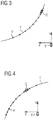
- shows an illustration of a possible scenario where the trajectory of the object has a component parallel to the trajectory of the vehicle and the trajectory of the object bends away from the trajectory of the vehicle;
- Fig. 4
- shows an illustration of a possible scenario where the trajectory of the object has a component parallel to the trajectory of the vehicle and the trajectory of the object bends towards the trajectory of the vehicle;
- Fig. 5
- shows an illustration of a possible scenario where the trajectory of the object has a component anti-parallel to the trajectory of the vehicle and the trajectory of the object bends away from the trajectory of the vehicle;
- Fig. 6
- shows an illustration of a possible scenario where the trajectory of the object has a component anti-parallel to the trajectory of the vehicle and the trajectory of the object bends towards the trajectory of the vehicle;
- Fig. 7
- shows an illustration of a construction of an approximated trajectory;
- Fig. 8
- shows an illustration of the time dependence of a slope of a regression line through the spatial positions of the object, wherein the trajectory of the object is bent away from the current position of the vehicle;
- Fig. 9
- shows a top view on a possible scenario where the object is moving in a roundabout;
- Fig. 10
- shows an illustration of the time dependence of the slope of a regression line through the spatial positions of the object, where the object is bent towards the current position of the vehicle;
- Fig. 11
- shows a top view on a further possible scenario where the object is moving in a roundabout;
- Fig. 12
- shows a schematic block diagram of a vehicle according to an embodiment of the invention; and
- Fig. 13
- shows a flowchart of a method for detecting a possible collision of the vehicle with a moving object.
- The accompanying drawings are included to provide a further understanding of the present invention and are incorporated in and constitute a part of this specification. The drawings illustrate particular embodiments of the invention and together with the description serve to explain the principles of the invention. Other embodiments of the invention and many of the attendant advantages of the invention will be readily appreciated as they become better understood with reference to the following detailed description.
- It will be appreciated that common and well understood elements that may be useful or necessary in a commercially feasible embodiment are not necessarily depicted in order to facilitate a more abstracted view of the embodiments. The elements of the drawings are not necessarily illustrated to scale relative to each other. It will further be appreciated that certain actions and/or steps in an embodiment of a method may be described or depicted in a particular order of occurrences while those skilled in the art will understand that such specificity with respect to sequence is not actually required. It will also be understood that the terms and expressions used in the present specification have the ordinary meaning as is accorded to such terms and expressions with respect to their corresponding respective areas of inquiry and study, except where specific meanings have otherwise been set forth herein.
-
Figure 1 shows a block diagram of a device 1 for detecting a possible collision of a vehicle V with a moving object O. A possible scenario is illustrated infigure 2 , where the vehicle V is driving towards a junction and the object O is another vehicle which is turning from the crossing road into the road of the vehicle V. - The device 1 comprises an
interface 2 which is adapted to receive sensor data obtained by the vehicle V. The sensor data may comprise radar data obtained by a radar system of the vehicle V, may comprise camera data obtained by a camera system of the vehicle V and/or may comprise infrared data obtained by an infrared sensor of the vehicle V. - The device 1 further comprises an evaluation unit 3 which is adapted to determine spatial positions p of the object O for a series of time points based on the sensor data received via the
interface 2. The spatial positions p refer to coordinates of the vehicle V relative to the fixed surrounding of the vehicle V, i.e., to absolute coordinates. The spatial positions p may comprise two-dimensional or three-dimensional coordinates of the object O. Preferably, the evaluation unit 3 is adapted to determine a set of spatial positions p, the set having a predetermined number of elements, for example 25 elements. The spatial positions p are recursively replaced using a first-in first-out principle. - For example, the relative spatial positions of the object O relative to the vehicle V can be determined in a first step. Further, the movement of the vehicle V is added in order to determine the spatial positions p of the object O.
- The evaluation unit 3 is further adapted to construct an approximated trajectory T of the object O by approximating the spatial positions p of the object O.
- According to an embodiment, the evaluation unit 3 is adapted to construct the approximated trajectory T using polynomial regression. As shown in
figure 2 , the evaluation unit 3 may construct the approximated trajectory T by using a third order polynomial which is fitted to the spatial positions p of the object O. Preferably, the polynomial is fitted in such a way that the least-square error is minimized. - Preferably, the curvature of the approximated trajectory T is computed. Based on the curvature, the evaluation unit 3 can determine if the object O is moving in a straight line or is turning left or right. A possible collision of the vehicle V with a moving object O can be determined based on the curvature of the approximated trajectory T. For example, if the approximated trajectory T bends towards the trajectory of the vehicle V, a possible collision is predicted.
- According to another embodiment, the last N positions p of the object O are determined and are saved in a list {p0,p1,...,pN-1}, where N can be any predetermined number, for example N=25. Based on the spatial positions p of the object O, smoothed positions {S0,S1,...,SN-1} are computed by smoothing the spatial positions p of the object O. Smoothing the spatial positions p may be performed using a Savitzky-Golay filter.
- From the smoothed spatial position, control points (b3j,b3j+1,b3j+2,b3j+3), j∈{0,...,L-1} are determined using De Boor's algorithm.
- For each set (b3j,b3j+1,b3j+2,b3j+3), j∈{0,...,L-1}, cubic Bezier curves are constructed which interpolate the set of the smoothed positions. Next, the partial curvatures kj are computed at the point b3j+3 for each set (b3j,b3j+1,b3j+2,b3j+3), j∈{0,...,L-1}, taking into consideration the value of the first and second derivative based on the control points. The curvature K for all spatial points p is calculated using the following formula:

- In
figure 3 , an illustrative scenario is shown. The vehicle V is moving along the x-axis, i.e. has a positive velocity component along the x-axis and zero velocity along the y-axis. The object O has a positive component of velocity vx along the trajectory of the vehicle V, i.e., along the x-axis. In other words, vx > 0. Further, vy < 0, i.e., the object O is moving towards the trajectory of the vehicle V. Moreover, the evaluation unit 3 has determined that the curvature is greater than or equal to zero, K ≥ 0. Depending on the sensor data, the evaluation unit 3 determines a time to collision. For example, the time to collision may be determined based on radar data. - The evaluation unit 3 is adapted to modify the determined time to collision based on the curvature K of the approximated trajectory T.
- In a first scenario, the curvature K is greater than or equal to zero and less than a predetermined positive first curvature threshold


- In a second scenario, the curvature K is greater than or equal to the first curvature threshold


- In a third scenario, the curvature K is greater than or equal to the second curvature threshold


- Accordingly, the time to collision is multiplied by an exponential factor involving the curvature K of the approximated trajectory T, if the curvature lies within a predetermined interval.
- In
figure 4 , a further illustrative scenario is shown which differs from the scenario illustrated infigure 3 in that the evaluation unit 3 has determined that the curvature K is smaller than zero, K < 0. - In a first scenario, the curvature is less than zero and greater than a predetermined negative third curvature threshold


- In a second scenario, the curvature is less than or equal to the third curvature threshold


- In
figure 5 , a further illustrative scenario is shown, where the object O has a component of velocity vx anti-parallel to the trajectory of the vehicle V, i.e. vx < 0. Further, vy < 0, i.e., the object O is moving towards the trajectory of the vehicle V. Moreover, the evaluation unit 3 has determined that the curvature is less than or equal to zero, K ≤ 0. - In a first scenario, the curvature K is greater than the third curvature threshold


- In a second scenario, the curvature K is less than or equal to the third curvature threshold


- In a third scenario, the curvature is smaller than or equal to the fourth curvature threshold


- In
figure 6 , a further illustrative scenario is shown which differs from the scenario illustrated infigure 5 in that the curvature K has been determined to be greater than zero, K > 0. - In a first scenario, the curvature K is greater than zero and smaller than the first curvature threshold,

- In a second scenario, the curvature K is greater than or equal to the first curvature threshold,

- According to a further embodiment, the approximated trajectory T is constructed as a regression line through the spatial positions p, as illustrated in
figure 7 . The slope fSlope of the regression line is computed according to the following formula:
- In this formula, N denotes the number of spatial positions p and xi and yi denote the longitudinal coordinate and lateral coordinate, respectively, for each position p.
- Further, the target angle α denotes the angle between the regression line and the x-axis. The slope fSlope and the target angle α differ by 90°.
- The detection of a possible collision of the object O with the vehicle V is now determined based on the target angle α of the approximated trajectory T. Further, if the value of the target angle α lies within a predetermined interval chosen around 0° or within a predetermined interval chosen around 180°, it is predicted that there is no possible collision of the vehicle V with the object O, because the object O is moving almost in parallel with the vehicle V.
- In contrast, if the value of the target angle α significantly differs from a value of 0° or 180°, a further analysis is performed in order to determine whether there is a possible collision of the vehicle V with the object O.
-
Figure 8 shows an illustrative scenario. The target angle α is computed for respective regression lines T1, T2 at two different time points t1 and t2. For each time point, the last N spatial positions p are used in order to determine the respective regression lines T1, T2. Now, the difference angle Δα between the target angles α1, α2 at the respective time points t1, t2 is computed according to the following formula:
- Further, an indicator fGradientTargetAngle is determined according to the following formula:

- Based on the indicator fGradientTargetAngle, the evaluation unit 3 may be adapted to predict a possible collision of the vehicle V with the object O.
- For example, as illustrated in
figure 9 , the object O may be another vehicle V which is driving in a roundabout. If the indicator fGradientTargetAngle is greater than or equal to a predetermined positive first value, it is determined that the object O is following a sharp curve and stays within the roundabout. It is determined that there is no possible collision of the vehicle V with the object O. This correspond to scenario c1 infigure 9 . - If it is concluded that the indicator fGradientTargetAngle is smaller than the first predetermined value but greater than or equal to a predetermined positive second value, it is determined that the object O follows a slight curve. In this case, it is determined that there is a possible collision between the object O and the vehicle V which corresponds to scenario c2.
- If the indicator fGradientTargetAngle is smaller than the second value and greater than 0, it is determined that the object O is following almost a straight line and a possible collision is predicted. This corresponds to scenario c3.
- The invention can also be used to determine if the vehicle V is exiting the roundabout. In
figure 10 , the respective regression lines T1, T2 of the object O are depicted at two different time points t1, t2.Figure 11 shows an illustrative scenario. If it is determined that the indicator fGradientTargetAngle is smaller than a predetermined negative third value, it is determined that the object O follows a sharp curve and correspondingly is exiting the roundabout, corresponding to scenario c1'. It is predicted that there is no collision. - If the indicator fGradientTargetAngle is greater than the third value and less than or equal to a predetermined negative fourth value, it is determined that the object O is following a slight curve, corresponding to scenario c2'. In this case, a possible collision of the vehicle V with the object O is predicted.
- If it is determined that the indicator fGradientTargetAngle is greater than the fourth value and smaller than or equal to zero it is determined that the object O is following almost a straight line and a possible collision is predicted, corresponding to scenario c3'.
- According to a further embodiment, the spatial positions p of the object O can also be determined relative to a vehicle-fixed coordinate system, i.e., the spatial positions p are determined relative to a coordinate system where the vehicle V is in the center and where preferably the x-axis is pointing along the movement direction of the vehicle V.
-
Figure 12 shows a block diagram of a vehicle V according to an embodiment of the invention. The vehicle V comprises a sensor system 4 which is adapted to provide sensor data of a surrounding of the vehicle V. The sensor system 4 may comprise a radar system, vehicle cameras or infrared sensors. - Further, the vehicle V comprises a device 1 for predicting a possible collision of the vehicle V with a moving object O. The device 1 is arranged according to one of the embodiments described above.
- The vehicle V further comprises a
control unit 5 which is adapted to control a movement of the vehicle V if a possible collision of the vehicle V with an object O has been predicted. For example, thecontrol unit 5 can be adapted to slow down the vehicle V or to steer the vehicle V away from the object O. -
Figure 13 shows a flowchart of a method for detecting a possible collision of a vehicle V with a moving object O according to an embodiment of the invention. - In a first step S1, spatial positions p of the object O are determined for a series of time points based on sensor data obtained by the vehicle V.
- In a second step, an approximated trajectory T of the object O is constructed by approximating the spatial positions p of the object O. The approximated trajectory T may be constructed using polynomial regression or using De Boor's algorithm, as explained in detail above.
- In a further step S3, a possible collision of the vehicle V with the object O is predicted based on the approximated trajectory T of the object O and/or based on a time dependence of the approximated trajectory T of the object O. The prediction can be performed according to one of the above mentioned methods. For example, a time to collision may be determined based on the sensor data obtained by the sensor system 4, and by modifying the time to collision based on the approximated trajectory T and/or based on the time dependence of the approximated trajectory T. In particular, the time to collision can be multiplied by an exponential factor which involves a curvature of the approximated trajectory T.
- Further, a probability for a collision of the vehicle V with the object O can be computed based on the approximated trajectory T.
- Although specific embodiments of the invention have been illustrated and described herein, it will be appreciated by those of ordinary skill in the art that a variety of alternate and/or equivalent implementations exist. It should be appreciated that the exemplary embodiment or exemplary embodiments are only examples, and are not intended to limit the scope, applicability, or configuration in any way. Rather, the foregoing summary and detailed description will provide those skilled in the art with a convenient road map for implementing at least one exemplary embodiment, it being understood that various changes may be made in the function and arrangement of elements described in an exemplary embodiment without departing from the scope as set forth in the appended claims and their legal equivalents. Generally, this application is intended to cover any adaptations or variations of the specific embodiments discussed herein.
- In this document, the terms "comprise", "comprising", "include", "including", "contain", "containing", "have", "having", and any variations thereof, are intended to be understood in an inclusive (i.e. non-exclusive) sense, such that the process, method, device, apparatus or system described herein is not limited to those features or parts or elements or steps recited but may include other elements, features, parts or steps not expressly listed or inherent to such process, method, article, or apparatus. Furthermore, the terms "a" and "an" used herein are intended to be understood as meaning one or more unless explicitly stated otherwise. Moreover, the terms "first", "second", "third", etc. are used merely as labels, and are not intended to impose numerical requirements on or to establish a certain ranking of importance of their objects.
-
- 1
- device
- 2
- interface
- 3
- evaluation unit
- 4
- sensor system
- 5
- control unit
- fSlope
- slope of the regression line
- O
- object
- p
- spatial position
- T
- trajectory
- V
- vehicle
- α
- target angle
Claims (15)
- A method for detecting a possible collision of a vehicle (V) with a moving object (O), comprising the steps:determining (S1) spatial positions (p) of the object (O) for a series of time points based on sensor data obtained by the vehicle (V);constructing (S2) an approximated trajectory (T) of the object (O) by approximating the spatial positions (p) of the object (O); andpredicting (S3) a possible collision of the vehicle (V) with the object (O) based on the approximated trajectory (T) of the object (O) and/or based on a time-dependence of the approximated trajectory (T) of the object (O).
- The method according to claim 1, wherein a possible collision of the vehicle (V) with the object (O) is predicted based on a curvature (K) of the approximated trajectory (T) of the object (O).
- The method according to claims 1 or 2, wherein constructing the approximated trajectory (T) comprises the following steps:computing smoothed positions (p) by smoothing the spatial positions (p) of the object (O); andconstructing the approximated trajectory (T) as an interpolated curve for the smoothed positions (p) using De Boor's algorithm.
- The method according to claim 3, wherein smoothing the spatial positions (p) is performed using a Savitzky-Golay filter.
- The method according to any of the preceding claims,
wherein the approximated trajectory (T) is constructed using polynomial regression. - The method according to any of the preceding claims,
wherein the approximated trajectory (T) is constructed as a regression line through the spatial positions (p), and wherein a possible collision of the vehicle (V) with the object (O) is predicted based on a time-dependence of a slope of the regression line. - The method according to any of the preceding claims,
wherein a time to collision (tc) is determined based on the sensor data, and wherein the time to collision (tc) is modified based on the approximated trajectory (T) and/or based on the time-dependence of the approximated trajectory (T). - The method according to claim 7, wherein modifying the time to collision (tc) comprises multiplying the time to collision (tc) by an exponential factor involving a curvature (K) of the approximated trajectory (T) if the curvature (K) of the approximated trajectory (T) lies within a predetermined interval.
- The method according to any of the preceding claims,
wherein a probability for a collision of the vehicle (V) with the object (O) is computed based on the approximated trajectory (T) and/or based on a time dependence of the approximated trajectory. - The method according to any of the preceding claims,
wherein a movement of the vehicle (V) is controlled if a possible collision of the vehicle (V) with the object (O) has been predicted. - A device (1) for detecting a possible collision of a vehicle (V) with a moving object (O), comprising:an interface (2) adapted to receive sensor data obtained by the vehicle (V);an evaluation unit (3), adapted to- determine spatial positions (p) of the object (O) for a series of time points based on the received sensor data;- construct an approximated trajectory (T) of the object (O) by approximating the spatial positions (p) of the object (O); and- predict a possible collision of the vehicle (V) with the object (O) based on the approximated trajectory of the object (O) and/or based on a time-dependence of the approximated trajectory of the object (O).
- The device (1) according to claim 11, wherein the evaluation unit (3) is adapted to construct the approximated trajectory (T) using polynomial regression.
- The device (1) according to claims 11 or 12, wherein the evaluation unit (3) is further adapted to determine a time to collision (tc) based on the sensor data, and to modify the time to collision (tc) based on the approximated trajectory (T).
- A vehicle (V), comprising
a sensor system (4) adapted to provide sensor data of a surrounding of the vehicle (V); and
a device (1) according to any of claims 11 to 13, for predicting a possible collision of the vehicle (V) with a moving object (O), based on the provided sensor data. - The vehicle (V) according to claim 14, comprising a control unit (5) which is adapted to control a movement of the vehicle (V) if a possible collision of the vehicle (V) with an object (O) has been predicted.
Priority Applications (1)
| Application Number | Priority Date | Filing Date | Title |
|---|---|---|---|
| EP17465504.3A EP3364211B1 (en) | 2017-02-21 | 2017-02-21 | Method and device for detecting a possible collision, and vehicle |
Applications Claiming Priority (1)
| Application Number | Priority Date | Filing Date | Title |
|---|---|---|---|
| EP17465504.3A EP3364211B1 (en) | 2017-02-21 | 2017-02-21 | Method and device for detecting a possible collision, and vehicle |
Publications (2)
| Publication Number | Publication Date |
|---|---|
| EP3364211A1 true EP3364211A1 (en) | 2018-08-22 |
| EP3364211B1 EP3364211B1 (en) | 2022-08-17 |
Family
ID=58464490
Family Applications (1)
| Application Number | Title | Priority Date | Filing Date |
|---|---|---|---|
| EP17465504.3A Active EP3364211B1 (en) | 2017-02-21 | 2017-02-21 | Method and device for detecting a possible collision, and vehicle |
Country Status (1)
| Country | Link |
|---|---|
| EP (1) | EP3364211B1 (en) |
Cited By (2)
| Publication number | Priority date | Publication date | Assignee | Title |
|---|---|---|---|---|
| WO2020160794A1 (en) * | 2019-02-04 | 2020-08-13 | Bayerische Motoren Werke Aktiengesellschaft | Method, device, computer program and computer program product for providing a trajectory of an object for a vehicle |
| CN114578401A (en) * | 2022-04-29 | 2022-06-03 | 泽景(西安)汽车电子有限责任公司 | Method and device for generating lane track points, electronic equipment and storage medium |
Citations (9)
| Publication number | Priority date | Publication date | Assignee | Title |
|---|---|---|---|---|
| US20020044081A1 (en) * | 2000-06-08 | 2002-04-18 | Shan Cong | Track map generator |
| US6615138B1 (en) * | 2002-05-30 | 2003-09-02 | Delphi Technologies, Inc. | Collision detection system and method of estimating miss distance employing curve fitting |
| US20030220728A1 (en) * | 2002-05-24 | 2003-11-27 | Rao Manoharprasad K. | Vehicle pre-crash sensing based conic target threat assessment system |
| JP2008222164A (en) * | 2007-03-15 | 2008-09-25 | Toyota Motor Corp | Course prediction device and collision prediction device |
| US20120313806A1 (en) * | 2009-12-08 | 2012-12-13 | Toyota Jidosha Kabushiki Kaisha | Object detecting apparatus and object detecting method |
| WO2013121357A1 (en) | 2012-02-15 | 2013-08-22 | Mobileye Technologies Limited | Time to collision using a camera |
| US20150183431A1 (en) * | 2012-08-08 | 2015-07-02 | Toyota Jidosha Kabushiki Kaisha | Collision prediction apparatus |
| US20160039413A1 (en) * | 2013-04-26 | 2016-02-11 | Bayerische Motoren Werke Aktiengesellschaft | Method for Determining a Lane Course of a Lane |
| US20160101779A1 (en) * | 2013-05-31 | 2016-04-14 | Toyota Jidosha Kabushiki Kaisha | Movement trajectory predicting device and movement trajectory predicting method |
-
2017
- 2017-02-21 EP EP17465504.3A patent/EP3364211B1/en active Active
Patent Citations (9)
| Publication number | Priority date | Publication date | Assignee | Title |
|---|---|---|---|---|
| US20020044081A1 (en) * | 2000-06-08 | 2002-04-18 | Shan Cong | Track map generator |
| US20030220728A1 (en) * | 2002-05-24 | 2003-11-27 | Rao Manoharprasad K. | Vehicle pre-crash sensing based conic target threat assessment system |
| US6615138B1 (en) * | 2002-05-30 | 2003-09-02 | Delphi Technologies, Inc. | Collision detection system and method of estimating miss distance employing curve fitting |
| JP2008222164A (en) * | 2007-03-15 | 2008-09-25 | Toyota Motor Corp | Course prediction device and collision prediction device |
| US20120313806A1 (en) * | 2009-12-08 | 2012-12-13 | Toyota Jidosha Kabushiki Kaisha | Object detecting apparatus and object detecting method |
| WO2013121357A1 (en) | 2012-02-15 | 2013-08-22 | Mobileye Technologies Limited | Time to collision using a camera |
| US20150183431A1 (en) * | 2012-08-08 | 2015-07-02 | Toyota Jidosha Kabushiki Kaisha | Collision prediction apparatus |
| US20160039413A1 (en) * | 2013-04-26 | 2016-02-11 | Bayerische Motoren Werke Aktiengesellschaft | Method for Determining a Lane Course of a Lane |
| US20160101779A1 (en) * | 2013-05-31 | 2016-04-14 | Toyota Jidosha Kabushiki Kaisha | Movement trajectory predicting device and movement trajectory predicting method |
Cited By (6)
| Publication number | Priority date | Publication date | Assignee | Title |
|---|---|---|---|---|
| WO2020160794A1 (en) * | 2019-02-04 | 2020-08-13 | Bayerische Motoren Werke Aktiengesellschaft | Method, device, computer program and computer program product for providing a trajectory of an object for a vehicle |
| CN113330449A (en) * | 2019-02-04 | 2021-08-31 | 宝马股份公司 | Method, device, computer program and computer program product for providing a trajectory profile of an object for a vehicle |
| US12014551B2 (en) | 2019-02-04 | 2024-06-18 | Bayerische Motoren Werke Aktiengesellschaft | Method, device, computer program and computer program product for providing a trajectory of an object for a vehicle |
| CN113330449B (en) * | 2019-02-04 | 2025-03-28 | 宝马股份公司 | Method, device and computer program product for providing a trajectory of an object to a vehicle |
| DE102019102679B4 (en) * | 2019-02-04 | 2026-01-29 | Bayerische Motoren Werke Aktiengesellschaft | Method, device, computer program and computer program product for providing a trajectory of an object to a vehicle for use in vehicle control functions |
| CN114578401A (en) * | 2022-04-29 | 2022-06-03 | 泽景(西安)汽车电子有限责任公司 | Method and device for generating lane track points, electronic equipment and storage medium |
Also Published As
| Publication number | Publication date |
|---|---|
| EP3364211B1 (en) | 2022-08-17 |
Similar Documents
| Publication | Publication Date | Title |
|---|---|---|
| EP2865575B1 (en) | Confidence estimation for predictive driver assistance systems based on plausibility rules | |
| CN107031650B (en) | Predicting vehicle motion based on driver limb language | |
| US10759422B2 (en) | Device for controlling vehicle at intersection | |
| JP5410730B2 (en) | Automobile external recognition device | |
| CN108230731B (en) | Parking lot navigation system and method | |
| US9400897B2 (en) | Method for classifying parking scenarios for a system for parking a motor vehicle | |
| JP6321532B2 (en) | Vehicle travel control device | |
| CN106891888B (en) | Vehicle turn signal detection | |
| US10124730B2 (en) | Vehicle lane boundary position | |
| US9809223B2 (en) | Driving assistant for vehicles | |
| US10410521B2 (en) | Method for determining an evasive path for a host vehicle | |
| EP2549456B1 (en) | Driving assistance device | |
| EP3106836A1 (en) | A unit and method for adjusting a road boundary | |
| US20190318627A1 (en) | Method for Checking a Passing Possibility Condition | |
| CN110194162B (en) | System and method for detecting an approaching cut-in vehicle based on available spatial signals | |
| EP3456596A1 (en) | Method and device of predicting a possible collision | |
| CN102959600A (en) | Device for estimating vehicle travel path | |
| CN114942430B (en) | Method and system for multi-hypothesis based fusion of sensor data | |
| JP6500724B2 (en) | Danger information notification system, server and computer program | |
| JP6259680B2 (en) | Safety confirmation determination device and driving support device | |
| KR20180039900A (en) | Apparatus and method for determining collision possibility according to traveling path scenario and controlling a vehicle | |
| EP3477333B1 (en) | Method and device of determining kinematics of a target | |
| JP5067091B2 (en) | Collision determination device | |
| EP3364211A1 (en) | Method and device for detecting a possible collision, and vehicle | |
| EP2835794A1 (en) | Method for warning the driver of a motor vehicle depending on a determined time to collision, camera system and motor vehicle |
Legal Events
| Date | Code | Title | Description |
|---|---|---|---|
| PUAI | Public reference made under article 153(3) epc to a published international application that has entered the european phase |
Free format text: ORIGINAL CODE: 0009012 |
|
| STAA | Information on the status of an ep patent application or granted ep patent |
Free format text: STATUS: THE APPLICATION HAS BEEN PUBLISHED |
|
| AK | Designated contracting states |
Kind code of ref document: A1 Designated state(s): AL AT BE BG CH CY CZ DE DK EE ES FI FR GB GR HR HU IE IS IT LI LT LU LV MC MK MT NL NO PL PT RO RS SE SI SK SM TR |
|
| AX | Request for extension of the european patent |
Extension state: BA ME |
|
| STAA | Information on the status of an ep patent application or granted ep patent |
Free format text: STATUS: REQUEST FOR EXAMINATION WAS MADE |
|
| 17P | Request for examination filed |
Effective date: 20190222 |
|
| RBV | Designated contracting states (corrected) |
Designated state(s): AL AT BE BG CH CY CZ DE DK EE ES FI FR GB GR HR HU IE IS IT LI LT LU LV MC MK MT NL NO PL PT RO RS SE SI SK SM TR |
|
| RAP1 | Party data changed (applicant data changed or rights of an application transferred) |
Owner name: CONTINENTAL AUTOMOTIVE GMBH |
|
| STAA | Information on the status of an ep patent application or granted ep patent |
Free format text: STATUS: EXAMINATION IS IN PROGRESS |
|
| 17Q | First examination report despatched |
Effective date: 20201124 |
|
| GRAP | Despatch of communication of intention to grant a patent |
Free format text: ORIGINAL CODE: EPIDOSNIGR1 |
|
| STAA | Information on the status of an ep patent application or granted ep patent |
Free format text: STATUS: GRANT OF PATENT IS INTENDED |
|
| RIC1 | Information provided on ipc code assigned before grant |
Ipc: G01S 13/931 20200101ALI20220308BHEP Ipc: B60W 30/095 20120101ALI20220308BHEP Ipc: G01S 13/93 20060101ALI20220308BHEP Ipc: G01S 13/72 20060101AFI20220308BHEP |
|
| INTG | Intention to grant announced |
Effective date: 20220401 |
|
| GRAS | Grant fee paid |
Free format text: ORIGINAL CODE: EPIDOSNIGR3 |
|
| GRAA | (expected) grant |
Free format text: ORIGINAL CODE: 0009210 |
|
| STAA | Information on the status of an ep patent application or granted ep patent |
Free format text: STATUS: THE PATENT HAS BEEN GRANTED |
|
| RAP1 | Party data changed (applicant data changed or rights of an application transferred) |
Owner name: CONTINENTAL AUTONOMOUS MOBILITY GERMANY GMBH |
|
| AK | Designated contracting states |
Kind code of ref document: B1 Designated state(s): AL AT BE BG CH CY CZ DE DK EE ES FI FR GB GR HR HU IE IS IT LI LT LU LV MC MK MT NL NO PL PT RO RS SE SI SK SM TR |
|
| REG | Reference to a national code |
Ref country code: CH Ref legal event code: EP |
|
| REG | Reference to a national code |
Ref country code: DE Ref legal event code: R096 Ref document number: 602017060704 Country of ref document: DE |
|
| REG | Reference to a national code |
Ref country code: IE Ref legal event code: FG4D |
|
| REG | Reference to a national code |
Ref country code: AT Ref legal event code: REF Ref document number: 1512533 Country of ref document: AT Kind code of ref document: T Effective date: 20220915 |
|
| REG | Reference to a national code |
Ref country code: NL Ref legal event code: MP Effective date: 20220817 |
|
| REG | Reference to a national code |
Ref country code: LT Ref legal event code: MG9D |
|
| PG25 | Lapsed in a contracting state [announced via postgrant information from national office to epo] |
Ref country code: SE Free format text: LAPSE BECAUSE OF FAILURE TO SUBMIT A TRANSLATION OF THE DESCRIPTION OR TO PAY THE FEE WITHIN THE PRESCRIBED TIME-LIMIT Effective date: 20220817 Ref country code: RS Free format text: LAPSE BECAUSE OF FAILURE TO SUBMIT A TRANSLATION OF THE DESCRIPTION OR TO PAY THE FEE WITHIN THE PRESCRIBED TIME-LIMIT Effective date: 20220817 Ref country code: PT Free format text: LAPSE BECAUSE OF FAILURE TO SUBMIT A TRANSLATION OF THE DESCRIPTION OR TO PAY THE FEE WITHIN THE PRESCRIBED TIME-LIMIT Effective date: 20221219 Ref country code: NO Free format text: LAPSE BECAUSE OF FAILURE TO SUBMIT A TRANSLATION OF THE DESCRIPTION OR TO PAY THE FEE WITHIN THE PRESCRIBED TIME-LIMIT Effective date: 20221117 Ref country code: NL Free format text: LAPSE BECAUSE OF FAILURE TO SUBMIT A TRANSLATION OF THE DESCRIPTION OR TO PAY THE FEE WITHIN THE PRESCRIBED TIME-LIMIT Effective date: 20220817 Ref country code: LV Free format text: LAPSE BECAUSE OF FAILURE TO SUBMIT A TRANSLATION OF THE DESCRIPTION OR TO PAY THE FEE WITHIN THE PRESCRIBED TIME-LIMIT Effective date: 20220817 Ref country code: LT Free format text: LAPSE BECAUSE OF FAILURE TO SUBMIT A TRANSLATION OF THE DESCRIPTION OR TO PAY THE FEE WITHIN THE PRESCRIBED TIME-LIMIT Effective date: 20220817 Ref country code: FI Free format text: LAPSE BECAUSE OF FAILURE TO SUBMIT A TRANSLATION OF THE DESCRIPTION OR TO PAY THE FEE WITHIN THE PRESCRIBED TIME-LIMIT Effective date: 20220817 |
|
| REG | Reference to a national code |
Ref country code: AT Ref legal event code: MK05 Ref document number: 1512533 Country of ref document: AT Kind code of ref document: T Effective date: 20220817 |
|
| PG25 | Lapsed in a contracting state [announced via postgrant information from national office to epo] |
Ref country code: PL Free format text: LAPSE BECAUSE OF FAILURE TO SUBMIT A TRANSLATION OF THE DESCRIPTION OR TO PAY THE FEE WITHIN THE PRESCRIBED TIME-LIMIT Effective date: 20220817 Ref country code: IS Free format text: LAPSE BECAUSE OF FAILURE TO SUBMIT A TRANSLATION OF THE DESCRIPTION OR TO PAY THE FEE WITHIN THE PRESCRIBED TIME-LIMIT Effective date: 20221217 Ref country code: HR Free format text: LAPSE BECAUSE OF FAILURE TO SUBMIT A TRANSLATION OF THE DESCRIPTION OR TO PAY THE FEE WITHIN THE PRESCRIBED TIME-LIMIT Effective date: 20220817 Ref country code: GR Free format text: LAPSE BECAUSE OF FAILURE TO SUBMIT A TRANSLATION OF THE DESCRIPTION OR TO PAY THE FEE WITHIN THE PRESCRIBED TIME-LIMIT Effective date: 20221118 |
|
| PG25 | Lapsed in a contracting state [announced via postgrant information from national office to epo] |
Ref country code: SM Free format text: LAPSE BECAUSE OF FAILURE TO SUBMIT A TRANSLATION OF THE DESCRIPTION OR TO PAY THE FEE WITHIN THE PRESCRIBED TIME-LIMIT Effective date: 20220817 Ref country code: RO Free format text: LAPSE BECAUSE OF FAILURE TO SUBMIT A TRANSLATION OF THE DESCRIPTION OR TO PAY THE FEE WITHIN THE PRESCRIBED TIME-LIMIT Effective date: 20220817 Ref country code: ES Free format text: LAPSE BECAUSE OF FAILURE TO SUBMIT A TRANSLATION OF THE DESCRIPTION OR TO PAY THE FEE WITHIN THE PRESCRIBED TIME-LIMIT Effective date: 20220817 Ref country code: DK Free format text: LAPSE BECAUSE OF FAILURE TO SUBMIT A TRANSLATION OF THE DESCRIPTION OR TO PAY THE FEE WITHIN THE PRESCRIBED TIME-LIMIT Effective date: 20220817 Ref country code: CZ Free format text: LAPSE BECAUSE OF FAILURE TO SUBMIT A TRANSLATION OF THE DESCRIPTION OR TO PAY THE FEE WITHIN THE PRESCRIBED TIME-LIMIT Effective date: 20220817 Ref country code: AT Free format text: LAPSE BECAUSE OF FAILURE TO SUBMIT A TRANSLATION OF THE DESCRIPTION OR TO PAY THE FEE WITHIN THE PRESCRIBED TIME-LIMIT Effective date: 20220817 |
|
| REG | Reference to a national code |
Ref country code: DE Ref legal event code: R097 Ref document number: 602017060704 Country of ref document: DE |
|
| PG25 | Lapsed in a contracting state [announced via postgrant information from national office to epo] |
Ref country code: SK Free format text: LAPSE BECAUSE OF FAILURE TO SUBMIT A TRANSLATION OF THE DESCRIPTION OR TO PAY THE FEE WITHIN THE PRESCRIBED TIME-LIMIT Effective date: 20220817 Ref country code: EE Free format text: LAPSE BECAUSE OF FAILURE TO SUBMIT A TRANSLATION OF THE DESCRIPTION OR TO PAY THE FEE WITHIN THE PRESCRIBED TIME-LIMIT Effective date: 20220817 |
|
| PLBE | No opposition filed within time limit |
Free format text: ORIGINAL CODE: 0009261 |
|
| STAA | Information on the status of an ep patent application or granted ep patent |
Free format text: STATUS: NO OPPOSITION FILED WITHIN TIME LIMIT |
|
| PG25 | Lapsed in a contracting state [announced via postgrant information from national office to epo] |
Ref country code: AL Free format text: LAPSE BECAUSE OF FAILURE TO SUBMIT A TRANSLATION OF THE DESCRIPTION OR TO PAY THE FEE WITHIN THE PRESCRIBED TIME-LIMIT Effective date: 20220817 |
|
| 26N | No opposition filed |
Effective date: 20230519 |
|
| PG25 | Lapsed in a contracting state [announced via postgrant information from national office to epo] |
Ref country code: SI Free format text: LAPSE BECAUSE OF FAILURE TO SUBMIT A TRANSLATION OF THE DESCRIPTION OR TO PAY THE FEE WITHIN THE PRESCRIBED TIME-LIMIT Effective date: 20220817 |
|
| PG25 | Lapsed in a contracting state [announced via postgrant information from national office to epo] |
Ref country code: MC Free format text: LAPSE BECAUSE OF FAILURE TO SUBMIT A TRANSLATION OF THE DESCRIPTION OR TO PAY THE FEE WITHIN THE PRESCRIBED TIME-LIMIT Effective date: 20220817 |
|
| REG | Reference to a national code |
Ref country code: CH Ref legal event code: PL |
|
| REG | Reference to a national code |
Ref country code: BE Ref legal event code: MM Effective date: 20230228 |
|
| PG25 | Lapsed in a contracting state [announced via postgrant information from national office to epo] |
Ref country code: LU Free format text: LAPSE BECAUSE OF NON-PAYMENT OF DUE FEES Effective date: 20230221 Ref country code: LI Free format text: LAPSE BECAUSE OF NON-PAYMENT OF DUE FEES Effective date: 20230228 Ref country code: CH Free format text: LAPSE BECAUSE OF NON-PAYMENT OF DUE FEES Effective date: 20230228 |
|
| REG | Reference to a national code |
Ref country code: IE Ref legal event code: MM4A |
|
| PG25 | Lapsed in a contracting state [announced via postgrant information from national office to epo] |
Ref country code: IE Free format text: LAPSE BECAUSE OF NON-PAYMENT OF DUE FEES Effective date: 20230221 |
|
| PG25 | Lapsed in a contracting state [announced via postgrant information from national office to epo] |
Ref country code: BE Free format text: LAPSE BECAUSE OF NON-PAYMENT OF DUE FEES Effective date: 20230228 |
|
| PG25 | Lapsed in a contracting state [announced via postgrant information from national office to epo] |
Ref country code: IT Free format text: LAPSE BECAUSE OF FAILURE TO SUBMIT A TRANSLATION OF THE DESCRIPTION OR TO PAY THE FEE WITHIN THE PRESCRIBED TIME-LIMIT Effective date: 20220817 |
|
| PG25 | Lapsed in a contracting state [announced via postgrant information from national office to epo] |
Ref country code: BG Free format text: LAPSE BECAUSE OF FAILURE TO SUBMIT A TRANSLATION OF THE DESCRIPTION OR TO PAY THE FEE WITHIN THE PRESCRIBED TIME-LIMIT Effective date: 20220817 |
|
| PG25 | Lapsed in a contracting state [announced via postgrant information from national office to epo] |
Ref country code: BG Free format text: LAPSE BECAUSE OF FAILURE TO SUBMIT A TRANSLATION OF THE DESCRIPTION OR TO PAY THE FEE WITHIN THE PRESCRIBED TIME-LIMIT Effective date: 20220817 |
|
| REG | Reference to a national code |
Ref country code: DE Ref legal event code: R081 Ref document number: 602017060704 Country of ref document: DE Owner name: AUMOVIO AUTONOMOUS MOBILITY GERMANY GMBH, DE Free format text: FORMER OWNER: CONTINENTAL AUTONOMOUS MOBILITY GERMANY GMBH, 85057 INGOLSTADT, DE |
|
| PG25 | Lapsed in a contracting state [announced via postgrant information from national office to epo] |
Ref country code: CY Free format text: LAPSE BECAUSE OF FAILURE TO SUBMIT A TRANSLATION OF THE DESCRIPTION OR TO PAY THE FEE WITHIN THE PRESCRIBED TIME-LIMIT; INVALID AB INITIO Effective date: 20170221 |
|
| PG25 | Lapsed in a contracting state [announced via postgrant information from national office to epo] |
Ref country code: HU Free format text: LAPSE BECAUSE OF FAILURE TO SUBMIT A TRANSLATION OF THE DESCRIPTION OR TO PAY THE FEE WITHIN THE PRESCRIBED TIME-LIMIT; INVALID AB INITIO Effective date: 20170221 |
|
| PG25 | Lapsed in a contracting state [announced via postgrant information from national office to epo] |
Ref country code: TR Free format text: LAPSE BECAUSE OF FAILURE TO SUBMIT A TRANSLATION OF THE DESCRIPTION OR TO PAY THE FEE WITHIN THE PRESCRIBED TIME-LIMIT Effective date: 20220817 |
|
| PGFP | Annual fee paid to national office [announced via postgrant information from national office to epo] |
Ref country code: GB Payment date: 20260223 Year of fee payment: 10 |
|
| PGFP | Annual fee paid to national office [announced via postgrant information from national office to epo] |
Ref country code: DE Payment date: 20260228 Year of fee payment: 10 |
|
| PGFP | Annual fee paid to national office [announced via postgrant information from national office to epo] |
Ref country code: FR Payment date: 20260227 Year of fee payment: 10 |