EP3364201A1 - Method of identifying a fault in a railway electrification system - Google Patents
Method of identifying a fault in a railway electrification system Download PDFInfo
- Publication number
- EP3364201A1 EP3364201A1 EP17156734.0A EP17156734A EP3364201A1 EP 3364201 A1 EP3364201 A1 EP 3364201A1 EP 17156734 A EP17156734 A EP 17156734A EP 3364201 A1 EP3364201 A1 EP 3364201A1
- Authority
- EP
- European Patent Office
- Prior art keywords
- supply conductor
- fault
- voltage
- electrical power
- current
- Prior art date
- Legal status (The legal status is an assumption and is not a legal conclusion. Google has not performed a legal analysis and makes no representation as to the accuracy of the status listed.)
- Granted
Links
Images
Classifications
-
- G—PHYSICS
- G01—MEASURING; TESTING
- G01R—MEASURING ELECTRIC VARIABLES; MEASURING MAGNETIC VARIABLES
- G01R31/00—Arrangements for testing electric properties; Arrangements for locating electric faults; Arrangements for electrical testing characterised by what is being tested not provided for elsewhere
- G01R31/08—Locating faults in cables, transmission lines, or networks
Definitions
- This invention relates to a method of identifying a fault in a railway electrification system, and to an apparatus for identifying a fault in a railway electrification system.
- a method of identifying a fault in a railway electrification system comprising: an electrical power source; a supply conductor; a return conductor; a rail line; and a plurality of autotransformers, the supply conductor configured to supply electrical power from the electrical power source to a rail vehicle on the rail line, the return conductor configured to provide a current return path to the electrical power source, the rail line electrically connected to ground, each autotransformer arranged along the rail line and configured to electrically interconnect the supply conductor, return conductor and rail line, the method comprising the steps of:
- the role of autotransformers in a railway electrification system is to address the issue of voltage drops along the supply conductor.
- the inclusion of autotransformers in the railway electrification system renders it difficult to identify the type and location of a fault in the railway electrification system, which is detrimental to the safety and reliability of the railway electrification system.
- the presence of autotransformers in the railway electrification system means that the conventional methods for calculating the fault distance based on the linear relationship are no longer valid for a fault located between the supply conductor and ground.
- the presence of autotransformers makes it difficult to use conventional methods to identify the type of fault.
- the method of the invention advantageously overcomes the aforementioned problem associated with the inclusion of the autotransformers in that the method of the invention enables the reliable identification of the type and location of a fault in the railway electrification system by utilising voltage and current phasors determined from voltage and current measured at the electrical power source.
- the method of the invention does not require remote measurements to help identify the type and location of a fault in the railway electrification system. This beneficially results in a cheaper and less complex railway electrification system since there is not only no need to install remote sensors along the length of the railway electrification system but also no need to install and manage additional hardware associated with remote sensors, such as communication links and remote location devices.
- the electrical power source may be, but is not limited to, a feeder substation configured to feed power from a multi-phase AC electrical network.
- the supply conductor may be, but is not limited to, an overhead line conductor, which is also known as an overhead wire or catenary.
- the return conductor may be, but is not limited to, a feeder conductor.
- the supply conductor may be configured to supply electrical power from the electrical power source to a rail vehicle on the rail line in a variety of ways.
- the supply conductor may be configured to electrically couple with an electrical collector, such as a pantograph, of the rail vehicle in order to supply electrical power from the electrical power source to the rail vehicle.
- the supply conductor may be electrically coupled to the electrical collector via a separate contact wire.
- Each autotransformer is preferably arranged along the rail line and configured to electrically interconnect the supply conductor, return conductor and rail line such that the autotransformers are spaced apart at intervals (which may be regular or otherwise) to divide the railway electrification system into a plurality of sections.
- the method of the invention is preferably carried out using only the voltage and current phasors determined from voltage and current measured at the electrical power source, which may be or may be part of a substation.
- the determination of whether the fault is located between the supply and return conductors or between the supply conductor and ground may be based on only the voltage and current phasors and/or the determination of the location of the fault along the supply conductor may be based on only the voltage and current phasors.
- the determination of the voltage and current phasors from voltage and current measured at the electrical power source may be carried out in a variety of ways, examples of which are described as follows.
- the step of determining voltage and current phasors from voltage and current measured at the electrical power source may include filtering the measured voltage and current, for example filtering one or more decaying direct current components from the measured voltage and current.
- the step of determining voltage and current phasors from voltage and current measured at the electrical power source may include:
- the determination of whether the fault is located between the supply and return conductors or between the supply conductor and ground based on the voltage and current phasors may be carried out in a variety of ways, examples of which are described as follows.
- the step of determining, based on the voltage and current phasors, whether the fault is located between the supply and return conductors or between the supply conductor and ground may include:
- ⁇ Z is the additional impedance
- ⁇ Z real is the real part of ⁇ Z
- ⁇ Z imag is the imaginary part of ⁇ Z
- U ⁇ 1 is the voltage phasor
- ⁇ 1 is the current phasor
- z 1 is the positive sequence impedance of the supply conductor in ohms per length
- x 0 is the estimated distance of the fault from the electrical power source along the supply conductor
- the function real ( y ) defines taking the real part of the term y
- N floor x 0 D
- the function floor ( y ) defines giving the largest integer number
- the determination of whether the fault is located between the supply and return conductors or between the supply conductor and ground may be based on the following criterion: real U ⁇ 1 I ⁇ 1 ⁇ real z 1 ⁇ x 1 imag U ⁇ 1 I ⁇ 1 ⁇ imag z 1 ⁇ x 1 > K set
- U ⁇ 1 is the voltage phasor
- ⁇ 1 is the current phasor
- z 1 is the positive sequence impedance of the supply conductor in ohms per length
- x 1 is the corrected distance of the fault from the electrical power source along the supply conductor
- the function real ( y ) defines taking the real part of the term y
- the function imag(y) defines taking the imaginary part of the term y
- K set is the criterion threshold (which e.g.
- K set ctg (arg( z 1 )-5°)).
- the fault is determined to be located between the supply conductor and ground when the ratio exceeds the criterion threshold, and wherein the fault is determined to be located between the supply and return conductors when the ratio does not exceed the criterion threshold.
- the determination of the location of the fault along the supply conductor based on the voltage and current phasors may be carried out in a variety of ways, examples of which are described as follows.
- the step of determining, based on the voltage and current phasors, the location of the fault along the supply conductor may include determining the distance of the fault from the electrical power source along the supply conductor based on the imaginary parts of the voltage and current phasors and the impedance of the supply conductor in ohms per length.
- an apparatus for identifying a fault in a railway electrification system comprising: an electrical power source; a supply conductor; a return conductor; a rail line; and a plurality of autotransformers, the supply conductor configured to supply electrical power from the electrical power source to a rail vehicle on the rail line, the return conductor configured to provide a current return path to the electrical power source, the rail line electrically connected to ground, each autotransformer arranged along the rail line and configured to electrically interconnect the supply conductor, return conductor and rail line, the apparatus configured to:
- the apparatus may be configured to perform the steps of the method of the first aspect of the invention, or may be configured to perform any of the optional steps of the embodiments of the method of the first aspect of the invention.
- a railway electrification system comprising: an electrical power source; a supply conductor; a return conductor; a rail line; and a plurality of autotransformers, the supply conductor configured to supply electrical power from the electrical power source to a rail vehicle on the rail line, the return conductor configured to provide a current return path to the electrical power source, the rail line electrically connected to ground, each autotransformer arranged along the rail line and configured to electrically interconnect the supply conductor, return conductor and rail line, wherein the railway electrification system further comprises the apparatus of the second aspect of the invention.
- the railway electrification system may comprise the features of the apparatus of the second aspect of the invention, or may further comprise any of the optional features of the embodiments of the apparatus of the second aspect of the invention.
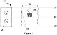
- a railway electrification system is shown in Figure 1 and is designated generally by the reference numeral 20.
- the railway electrification system 20 comprises an electrical power source, a supply conductor, a return conductor, a rail line 22, and a plurality of autotransformers 32.
- the rail line 22 lies along the surface of the ground and thereby is electrically connected to ground. In use, a rail vehicle 24 travels on the rail line 22.
- the electrical power source is in the form of a feeder substation 26 connected to two phases of a three-phase AC power grid (not shown) to enable it to feed power from the AC power grid.
- the supply conductor is in the form of a catenary 28 that is suspended from supporting towers (not shown) that are arranged along the length of the rail line 22.
- the return conductor is in the form of a feeder 30 that is also suspended from the supporting towers that are arranged along the length of the rail line 22.
- the autotransformers 32 are spaced apart at intervals along the length of the rail line 22 to divide the railway electrification system 20 into a plurality of sections. Each autotransformer 32 is arranged to be electrically connected between the catenary 28 and feeder 30, and also electrically connected to the grounded rail line 22.
- the catenary 28 is kept at a positive voltage, e.g. 25 kV, while the feeder 30 is kept at a negative voltage, e.g. - 25 kV. It is envisaged that the voltage of the catenary 28 and feeder 30 may have different values so long as a voltage drop is present across the catenary 28 and feeder 30 that permits the aforementioned circulation of current.
- each autotransformer 32 helps to maintain the voltage drop between the catenary 28 and feeder 30 along the length of the rail line 22.
- a fault may occur in the railway electrification system 20.
- This fault may be in the form of a catenary-to-feeder fault or a catenary-to-ground fault.
- the railway electrification system 20 comprises sensors configured to measure voltage and current at the feeder substation 26. More specifically the sensors are configured to measure the voltages u A ,u B and current i A ,i B of the two phases of the AC power grid connected to the feeder substation 26.
- the railway electrification system 20 further comprises an apparatus 34 for identifying the type and location of the fault.
- the apparatus 34 includes first, second and third processing blocks 34,36,38.
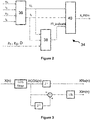
- a block diagram of the apparatus 34 is shown in Figure 2 .
- the function real ( y ) defines taking the real part of the term y
- the function imag(y) defines taking the imaginary part of the term y .
- the measured voltages u A ,u B and currents i A ,i B of the two phases of the AC power grid is fed into the first processing block 36, which includes a cosine filter shown in Figure 3 .
- the first processing block 36 then derives voltage and current phasors by filtering one or more decaying direct current components from the measured voltages u A ,u B and currents i A ,i B through the following steps:
- the derived voltage and current phasors are then fed into a second processing block 38.
- the positive sequence impedance z 1 of the catenary 28 in ohms per length, the zero sequence impedance z 0 of the catenary 28 in ohms per length, and the distance D between successive autotransformers 32 arranged along the rail line 22 are also fed into the second processing block 38.
- the second processing block 38 then processes the received information to determine whether the fault is located between the catenary 28 and feeder 30 or between the catenary 28 and ground.
- the positive-sequence impedance z 1 of the catenary 28 is defined as the self-impedance of the catenary 28 minus the mutual impedance between the catenary 28 and the feeder 30.
- the zero sequence impedance z 0 of the catenary 28 is defined as the self-impedance of the catenary 28 plus the mutual impedance between the catenary 28 and the feeder 30.
- the fault is determined to be located between the catenary 28 and ground when the ratio exceeds the criterion threshold, and wherein the fault is determined to be located between the catenary 28 and feeder 30 when the ratio does not exceed the criterion threshold.
- the second processing block outputs a signal FT_indicate that represents the determination of the location of the fault, and the signal FT_indicate is fed to a third processing block.
- the third processing block 40 outputs a signal X_FtDis that represents the distance of the fault from the feeder substation 26 along the catenary 28.
- the output signals FT_indicate,X_FtDis from the second and third processing blocks 36,38 may fed to a protection device which then automatically takes action to address the identified fault, or can be provided (e.g. using a display) to an operator who can then manually take action to address the identified fault.
- the method of the invention therefore enables the reliable identification of the type and location of a fault in the railway electrification system 20 by utilising voltage and current phasors determined from voltage and current measured at the feeder substation 26.
- the method of the invention does not require remote measurements to help identify the type and location of a fault in the railway electrification system 20.
- each numerical value given for the embodiment shown is merely chosen to help illustrate the working of the invention, and may be replaced by another numerical value.
- each equation given for the embodiment shown is merely chosen to help illustrate the working of the invention, and may be replaced by another equivalent equation performing the same function.
- the structure of the railway electrification system 20 and the layout of the apparatus 34 shown in the accompanying figures are intended to form non-limiting examples to demonstrate the working of the invention.
Landscapes
- Physics & Mathematics (AREA)
- General Physics & Mathematics (AREA)
- Locating Faults (AREA)
Abstract
determining voltage and current phasors from voltage and current measured at the electrical power source (26);
determining, based on the voltage and current phasors, whether the fault is located between the supply and return conductors (28,30) or between the supply conductor (28) and ground;
determining, based on the voltage and current phasors, the location of the fault along the supply conductor (28).
Description
- This invention relates to a method of identifying a fault in a railway electrification system, and to an apparatus for identifying a fault in a railway electrification system.
- It is known to supply electrical power to railway trains and trams by way of a railway electrification system.
- According to a first aspect of the invention, there is provided a method of identifying a fault in a railway electrification system, the railway electrification system comprising: an electrical power source; a supply conductor; a return conductor; a rail line; and a plurality of autotransformers, the supply conductor configured to supply electrical power from the electrical power source to a rail vehicle on the rail line, the return conductor configured to provide a current return path to the electrical power source, the rail line electrically connected to ground, each autotransformer arranged along the rail line and configured to electrically interconnect the supply conductor, return conductor and rail line, the method comprising the steps of:
- determining voltage and current phasors from voltage and current measured at the electrical power source;
- determining, based on the voltage and current phasors, whether the fault is located between the supply and return conductors or between the supply conductor and ground;
- determining, based on the voltage and current phasors, the location of the fault along the supply conductor.
- The role of autotransformers in a railway electrification system is to address the issue of voltage drops along the supply conductor. On the other hand, the inclusion of autotransformers in the railway electrification system renders it difficult to identify the type and location of a fault in the railway electrification system, which is detrimental to the safety and reliability of the railway electrification system. This is because, unlike conventional methods in which the fault distance is calculated based on a linear relationship between the fault distance and a measured impedance of the supply conductor, the presence of autotransformers in the railway electrification system means that the conventional methods for calculating the fault distance based on the linear relationship are no longer valid for a fault located between the supply conductor and ground. Also, the presence of autotransformers makes it difficult to use conventional methods to identify the type of fault.
- The method of the invention advantageously overcomes the aforementioned problem associated with the inclusion of the autotransformers in that the method of the invention enables the reliable identification of the type and location of a fault in the railway electrification system by utilising voltage and current phasors determined from voltage and current measured at the electrical power source.
- Moreover the method of the invention does not require remote measurements to help identify the type and location of a fault in the railway electrification system. This beneficially results in a cheaper and less complex railway electrification system since there is not only no need to install remote sensors along the length of the railway electrification system but also no need to install and manage additional hardware associated with remote sensors, such as communication links and remote location devices.
- The electrical power source may be, but is not limited to, a feeder substation configured to feed power from a multi-phase AC electrical network.
- The supply conductor may be, but is not limited to, an overhead line conductor, which is also known as an overhead wire or catenary.
- The return conductor may be, but is not limited to, a feeder conductor.
- The supply conductor may be configured to supply electrical power from the electrical power source to a rail vehicle on the rail line in a variety of ways. For example, the supply conductor may be configured to electrically couple with an electrical collector, such as a pantograph, of the rail vehicle in order to supply electrical power from the electrical power source to the rail vehicle. Furthermore the supply conductor may be electrically coupled to the electrical collector via a separate contact wire.
- Each autotransformer is preferably arranged along the rail line and configured to electrically interconnect the supply conductor, return conductor and rail line such that the autotransformers are spaced apart at intervals (which may be regular or otherwise) to divide the railway electrification system into a plurality of sections.
- It will be understood that, whilst the method of the invention is not restricted from being used in combination with another way of identifying a fault in a railway electrification system, the method of the invention is preferably carried out using only the voltage and current phasors determined from voltage and current measured at the electrical power source, which may be or may be part of a substation. Thus, in embodiments of the invention, the determination of whether the fault is located between the supply and return conductors or between the supply conductor and ground may be based on only the voltage and current phasors and/or the determination of the location of the fault along the supply conductor may be based on only the voltage and current phasors. This in turn results in a simpler method of identifying and locating a fault in a railway electrification system which avoids the extra costs associated with the use of additional measurements and corresponding communication devices, and additionally speeds up the determination of the fault type and location, which can be crucial in ensuring the safety and reliability of the railway electrification system.
- The determination of the voltage and current phasors from voltage and current measured at the electrical power source may be carried out in a variety of ways, examples of which are described as follows.
- The step of determining voltage and current phasors from voltage and current measured at the electrical power source may include filtering the measured voltage and current, for example filtering one or more decaying direct current components from the measured voltage and current.
- The step of determining voltage and current phasors from voltage and current measured at the electrical power source may include:
- (a) processing the measured voltage and current with a cosine filter based on the following equation:

- (b) determining the real part of each phasor based on the following equation:

- (c) determining the imaginary part of each phasor based on the following equation:


- The determination of whether the fault is located between the supply and return conductors or between the supply conductor and ground based on the voltage and current phasors may be carried out in a variety of ways, examples of which are described as follows.
- For example, the step of determining, based on the voltage and current phasors, whether the fault is located between the supply and return conductors or between the supply conductor and ground may include:
- (a) determining an estimated distance of the fault from the electrical power source along the supply conductor based on the voltage and current phasors and the positive sequence impedance of the supply conductor in ohms per length;
- (b) determining an additional impedance based on the voltage and current phasors, the positive sequence impedance of the supply conductor in ohms per length, the estimated distance of the fault from the electrical power source along the supply conductor, the zero sequence impedance in ohms per length, and the distance between successive autotransformers arranged along the rail line;
- (c) determining a corrected distance of the fault from the electrical power source along the supply conductor based on the additional impedance, the voltage and current phasors and the positive sequence impedance of the supply conductor in ohms per length;
- (d) determining whether the fault is located between the supply and return conductors or between the supply conductor and ground by comparing the ratio of first and second values against a criterion threshold, wherein the first value is based on the corrected distance and the real parts of the voltage and current phasors and the positive sequence impedance of the supply conductor in ohms per length, and the second value is based on the corrected distance and the imaginary parts of the voltage and current phasors and the positive sequence impedance of the supply conductor in ohms per length, wherein the fault is determined to be located between the supply conductor and ground when the ratio exceeds the criterion threshold, and wherein the fault is determined to be located between the supply and return conductors when the ratio does not exceed the criterion threshold.
- The estimated distance of the fault from the electrical power source along the supply conductor may be determined based on the following equation:

- The additional impedance may be determined based on the following equations:


- The corrected distance of the fault from the electrical power source along the supply conductor may be determined based on the following equation:

- The determination of whether the fault is located between the supply and return conductors or between the supply conductor and ground may be based on the following criterion:

- The determination of the location of the fault along the supply conductor based on the voltage and current phasors may be carried out in a variety of ways, examples of which are described as follows.
- For example, the step of determining, based on the voltage and current phasors, the location of the fault along the supply conductor may include determining the distance of the fault from the electrical power source along the supply conductor based on the imaginary parts of the voltage and current phasors and the impedance of the supply conductor in ohms per length.
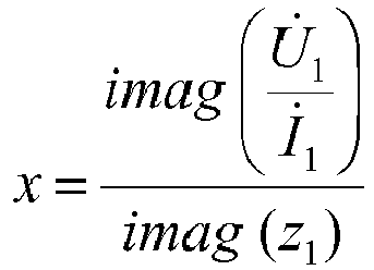
- The distance of the fault from the electrical power source along the supply conductor may be determined based on the following equation when the fault is between the supply conductor and ground:


- The distance of the fault from the electrical power source along the supply conductor may be determined based on the following equation when the fault is located between the supply and return conductors:
- According to a second aspect of the invention, there is provided an apparatus for identifying a fault in a railway electrification system, the railway electrification system comprising: an electrical power source; a supply conductor; a return conductor; a rail line; and a plurality of autotransformers, the supply conductor configured to supply electrical power from the electrical power source to a rail vehicle on the rail line, the return conductor configured to provide a current return path to the electrical power source, the rail line electrically connected to ground, each autotransformer arranged along the rail line and configured to electrically interconnect the supply conductor, return conductor and rail line, the apparatus configured to:
- determine voltage and current phasors from voltage and current measured at the electrical power source;
- determine, based on the voltage and current phasors, whether the fault is located between the supply and return conductors or between the supply conductor and ground;
- determine, based on the voltage and current phasors, the location of the fault along the supply conductor.
- The features and advantages of the method of the first aspect of the invention and its embodiments apply mutatis mutandis to the apparatus of the second aspect of the invention. In particular, the apparatus may be configured to perform the steps of the method of the first aspect of the invention, or may be configured to perform any of the optional steps of the embodiments of the method of the first aspect of the invention.
- According to a third aspect of the invention, there is provided a railway electrification system comprising: an electrical power source; a supply conductor; a return conductor; a rail line; and a plurality of autotransformers, the supply conductor configured to supply electrical power from the electrical power source to a rail vehicle on the rail line, the return conductor configured to provide a current return path to the electrical power source, the rail line electrically connected to ground, each autotransformer arranged along the rail line and configured to electrically interconnect the supply conductor, return conductor and rail line, wherein the railway electrification system further comprises the apparatus of the second aspect of the invention.
- The features and advantages of the apparatus of the second aspect of the invention and its embodiments apply mutatis mutandis to the railway electrification system of the third aspect of the invention. In particular, the railway electrification system may comprise the features of the apparatus of the second aspect of the invention, or may further comprise any of the optional features of the embodiments of the apparatus of the second aspect of the invention.
- A preferred embodiment of the invention will now be described, by way of a non-limiting example, with reference to the accompanying drawings in which:
-
Figure 1 shows schematically a railway electrification system according to an embodiment of the invention; and -
Figures 2 and 3 show schematically an exemplary apparatus of the railway electrification system ofFigure 1 . - A railway electrification system is shown in
Figure 1 and is designated generally by thereference numeral 20. - The
railway electrification system 20 comprises an electrical power source, a supply conductor, a return conductor, arail line 22, and a plurality ofautotransformers 32. Therail line 22 lies along the surface of the ground and thereby is electrically connected to ground. In use, arail vehicle 24 travels on therail line 22. - The electrical power source is in the form of a
feeder substation 26 connected to two phases of a three-phase AC power grid (not shown) to enable it to feed power from the AC power grid. The supply conductor is in the form of acatenary 28 that is suspended from supporting towers (not shown) that are arranged along the length of therail line 22. The return conductor is in the form of afeeder 30 that is also suspended from the supporting towers that are arranged along the length of therail line 22. Theautotransformers 32 are spaced apart at intervals along the length of therail line 22 to divide therailway electrification system 20 into a plurality of sections. Eachautotransformer 32 is arranged to be electrically connected between thecatenary 28 andfeeder 30, and also electrically connected to thegrounded rail line 22. - In order to power the
rail vehicle 24, electrical power is supplied from thefeeder substation 26 to therail vehicle 24. A contact wire is suspended from thecatenary 28 using vertical dropper wires, and the contact wire makes contact with a pantograph on top of therail vehicle 24. This results in the formation of a current path that allows current to flow from thefeeder substation 26 to thecatenary 28, to the pantograph via the contact wire, to the groundedrail line 22, to eachautotransformer 32, and to thefeeder 30 before returning to thefeeder substation 26. In this manner electrical power is supplied from thefeeder substation 26 to therail vehicle 24. - The
catenary 28 is kept at a positive voltage, e.g. 25 kV, while thefeeder 30 is kept at a negative voltage, e.g. - 25 kV. It is envisaged that the voltage of thecatenary 28 andfeeder 30 may have different values so long as a voltage drop is present across thecatenary 28 andfeeder 30 that permits the aforementioned circulation of current. - Meanwhile each
autotransformer 32 helps to maintain the voltage drop between thecatenary 28 andfeeder 30 along the length of therail line 22. - A fault may occur in the
railway electrification system 20. This fault may be in the form of a catenary-to-feeder fault or a catenary-to-ground fault. - The
railway electrification system 20 comprises sensors configured to measure voltage and current at thefeeder substation 26. More specifically the sensors are configured to measure the voltages uA,uB and current iA,iB of the two phases of the AC power grid connected to thefeeder substation 26. - The
railway electrification system 20 further comprises anapparatus 34 for identifying the type and location of the fault. Theapparatus 34 includes first, second and third processing blocks 34,36,38. A block diagram of theapparatus 34 is shown inFigure 2 . - In the following equations, the function real(y) defines taking the real part of the term y, and the function imag(y) defines taking the imaginary part of the term y.
- The measured voltages uA,uB and currents iA,iB of the two phases of the AC power grid is fed into the
first processing block 36, which includes a cosine filter shown inFigure 3 . Thefirst processing block 36 then derives voltage and current phasors by filtering one or more decaying direct current components from the measured voltages uA,uB and currents iA,iB through the following steps: - (a) processing the measured voltage and current with a cosine filter based on the following equation:

feeder substation 26; - (b) determining the real part of each phasor based on the following equation:

- (c) determining the imaginary part of each phasor based on the following equation:


- The derived voltage and current phasors are then fed into a
second processing block 38. In addition the positive sequence impedance z1 of thecatenary 28 in ohms per length, the zero sequence impedance z0 of thecatenary 28 in ohms per length, and the distance D betweensuccessive autotransformers 32 arranged along therail line 22 are also fed into thesecond processing block 38. Thesecond processing block 38 then processes the received information to determine whether the fault is located between thecatenary 28 andfeeder 30 or between thecatenary 28 and ground. - The positive-sequence impedance z1 of the
catenary 28 is defined as the self-impedance of thecatenary 28 minus the mutual impedance between thecatenary 28 and thefeeder 30. The zero sequence impedance z0 of thecatenary 28 is defined as the self-impedance of thecatenary 28 plus the mutual impedance between thecatenary 28 and thefeeder 30. - Firstly, the
second processing block 38 determines an estimated distance of the fault from thefeeder substation 26 along thecatenary 28 based on the following equation:
feeder substation 26 along thecatenary 28, U̇ 1 is the voltage phasor, İ 1 is the current phasor, z 1 is the positive sequence impedance of thecatenary 28 in ohms per length. - Secondly, the
second processing block 38 determines an additional impedance ΔZ based on the following equations:


feeder substation 26 along thecatenary 28,
catenary 28 in ohms per length, and D is the distance betweensuccessive autotransformers 32 arranged along therail line 22. - Thirdly, the
second processing block 38 determines a corrected distance of the fault from thefeeder substation 26 along thecatenary 28 based on the following equation:
feeder substation 26 along thecatenary 28. - Fourthly, the
second processing block 38 determines whether the fault is located between thecatenary 28 andfeeder 30 or between thecatenary 28 and ground based on the following criterion:
- The fault is determined to be located between the
catenary 28 and ground when the ratio exceeds the criterion threshold, and wherein the fault is determined to be located between thecatenary 28 andfeeder 30 when the ratio does not exceed the criterion threshold. The second processing block outputs a signal FT_indicate that represents the determination of the location of the fault, and the signal FT_indicate is fed to a third processing block. - The
third processing block 40 determines the distance of the fault from thefeeder substation 26 along thecatenary 28 based on the following equation when the fault is between thecatenary 28 and ground:
feeder substation 26 along thecatenary 28,

- The
third processing block 40 determines the distance of the fault from thefeeder substation 26 along thecatenary 28 based on the following equation when the fault is located between thecatenary 28 and feeder 30:
feeder substation 26 along thecatenary 28. - Finally, the
third processing block 40 outputs a signal X_FtDis that represents the distance of the fault from thefeeder substation 26 along thecatenary 28. - The output signals FT_indicate,X_FtDis from the second and third processing blocks 36,38 may fed to a protection device which then automatically takes action to address the identified fault, or can be provided (e.g. using a display) to an operator who can then manually take action to address the identified fault.
- The method of the invention therefore enables the reliable identification of the type and location of a fault in the
railway electrification system 20 by utilising voltage and current phasors determined from voltage and current measured at thefeeder substation 26. - Moreover the method of the invention does not require remote measurements to help identify the type and location of a fault in the
railway electrification system 20. This beneficially results in a cheaper and less complexrailway electrification system 20 since there is not only no need to install remote sensors along the length of therailway electrification system 20 but also no need to install and manage additional hardware associated with remote sensors, such as communication links and GPS devices. - It will be appreciated that each numerical value given for the embodiment shown is merely chosen to help illustrate the working of the invention, and may be replaced by another numerical value. It will also be appreciated that each equation given for the embodiment shown is merely chosen to help illustrate the working of the invention, and may be replaced by another equivalent equation performing the same function. It will be further appreciated that the structure of the
railway electrification system 20 and the layout of theapparatus 34 shown in the accompanying figures are intended to form non-limiting examples to demonstrate the working of the invention.
Claims (15)
- A method of identifying a fault in a railway electrification system (20), the railway electrification system (20) comprising: an electrical power source (26); a supply conductor (28); a return conductor (30); a rail line (22); and a plurality of autotransformers (32), the supply conductor (28) configured to supply electrical power from the electrical power source (26) to a rail vehicle (24) on the rail line (22), the return conductor (30) configured to provide a current return path to the electrical power source (26), the rail line (22) electrically connected to ground, each autotransformer (32) arranged along the rail line (22) and configured to electrically interconnect the supply conductor (28), return conductor (30) and rail line (22), the method comprising the steps of:determining voltage and current phasors from voltage and current measured at the electrical power source (26);determining, based on the voltage and current phasors, whether the fault is located between the supply and return conductors (28,30) or between the supply conductor (28) and ground;determining, based on the voltage and current phasors, the location of the fault along the supply conductor (28).
- A method according to Claim 1 wherein the determination of whether the fault is located between the supply and return conductors (28,30) or between the supply conductor (28) and ground is based on only the voltage and current phasors.
- A method according to Claim 1 or Claim 2 wherein the determination of the location of the fault along the supply conductor (28) is based on only the voltage and current phasors.
- A method according to any one of the preceding claims wherein the step of determining voltage and current phasors from voltage and current measured at the electrical power source (26) includes filtering one or more decaying direct current components from the measured voltage and current.
- A method according to any one of the preceding claims wherein the step of determining voltage and current phasors from voltage and current measured at the electrical power source (26) includes:(a) processing the measured voltage and current with a cosine filter based on the following equation:
 (b) determining the real part of each phasor based on the following equation:
 (c) determining the imaginary part of each phasor based on the following equation:

- A method according to any one of the preceding claims wherein the step of determining, based on the voltage and current phasors, whether the fault is located between the supply and return conductors (28,30) or between the supply conductor (28) and ground includes:(a) determining an estimated distance of the fault from the electrical power source (26) along the supply conductor (28) based on the voltage and current phasors and the positive sequence impedance (z1) of the supply conductor (28) in ohms per length;(b) determining an additional impedance (ΔZ) based on the voltage and current phasors, the positive sequence impedance (z1) of the supply conductor (28) in ohms per length, the estimated distance of the fault from the electrical power source (26) along the supply conductor (28), the zero-sequence impedance (z0) of the supply conductor (28) in ohms per length, and the distance (D) between successive autotransformers (32) arranged along the rail line (22);(c) determining a corrected distance of the fault from the electrical power source (26) along the supply conductor (28) based on the additional impedance (ΔZ), the voltage and current phasors and the positive sequence impedance (z1) of the supply conductor (28) in ohms per length;(d) determining whether the fault is located between the supply and return conductors (28,30) or between the supply conductor (28) and ground by comparing the ratio of first and second values against a criterion threshold, wherein the first value is based on the corrected distance and the real parts of the voltage and current phasors and the positive sequence impedance (z1) of the supply conductor (28) in ohms per length, and the second value is based on the corrected distance and the imaginary parts of the voltage and current phasors and the positive sequence impedance (z1) of the supply conductor (28) in ohms per length, wherein the fault is determined to be located between the supply conductor (28) and ground when the ratio exceeds the criterion threshold, and wherein the fault is determined to be located between the supply and return conductors (28,30) when the ratio does not exceed the criterion threshold.
- A method according to Claim 6 wherein the estimated distance of the fault from the electrical power source (26) along the supply conductor (28) is determined based on the following equation:

- A method according to Claim 6 or Claim 7 wherein the additional impedance is determined based on the following equations:


- A method according to any one of Claims 6 to 8 wherein the corrected distance of the fault from the electrical power source (26) along the supply conductor (28) is determined based on the following equation:

- A method according to any one of Claims 6 to 9 wherein the determination of whether the fault is located between the supply and return conductors (28,30) or between the supply conductor (28) and ground is based on the following criterion:

wherein the fault is determined to be located between the supply conductor (28) and ground when the ratio exceeds the criterion threshold, and wherein the fault is determined to be located between the supply and return conductors (28,30) when the ratio does not exceed the criterion threshold. - A method according to Claim 10 wherein the criterion threshold is given by Kset = ctg (arg (z 1)-5°).
- A method according to any one of the preceding claims wherein the step of determining, based on the voltage and current phasors, the location of the fault along the supply conductor (28) includes determining the distance of the fault from the electrical power source (26) along the supply conductor (28) based on the imaginary parts of the voltage and current phasors and the impedance of the supply conductor (28) in ohms per length.
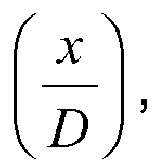
- A method according to Claim 12 wherein the distance of the fault from the electrical power source (26) along the supply conductor (28) is determined based on the following equation when the fault is between the supply conductor (28) and ground:


- A method according to Claim 12 or Claim 13 wherein the distance of the fault from the electrical power source (26) along the supply conductor (28) is determined based on the following equation when the fault is located between the supply and return conductors (28,30):

- An apparatus (34) for locating a fault in a railway electrification system (20), the railway electrification system (20) comprising: an electrical power source (26); a supply conductor (28); a return conductor (30); a rail line (22); and a plurality of autotransformers (32), the supply conductor (28) configured to supply electrical power from the electrical power source (26) to a rail vehicle (24) on the rail line (22), the return conductor (30) configured to provide a current return path to the electrical power source (26), the rail line (22) electrically connected to ground, each autotransformer (32) arranged along the rail line (22) and configured to electrically interconnect the supply conductor (28), return conductor (30) and rail line (22), the apparatus (34) configured to:determine voltage and current phasors from voltage and current measured at the electrical power source (26);determine, based on the voltage and current phasors, whether the fault is located between the supply and return conductors (28,30) or between the supply conductor (28) and ground;determine, based on the voltage and current phasors, the location of the fault along the supply conductor (28).
Priority Applications (2)
| Application Number | Priority Date | Filing Date | Title |
|---|---|---|---|
| EP17156734.0A EP3364201B1 (en) | 2017-02-17 | 2017-02-17 | Method of identifying a fault in a railway electrification system |
| PCT/EP2018/052304 WO2018149634A1 (en) | 2017-02-17 | 2018-01-30 | Method of identifying a fault in a railway electrification system |
Applications Claiming Priority (1)
| Application Number | Priority Date | Filing Date | Title |
|---|---|---|---|
| EP17156734.0A EP3364201B1 (en) | 2017-02-17 | 2017-02-17 | Method of identifying a fault in a railway electrification system |
Publications (2)
| Publication Number | Publication Date |
|---|---|
| EP3364201A1 true EP3364201A1 (en) | 2018-08-22 |
| EP3364201B1 EP3364201B1 (en) | 2022-03-30 |
Family
ID=58192088
Family Applications (1)
| Application Number | Title | Priority Date | Filing Date |
|---|---|---|---|
| EP17156734.0A Active EP3364201B1 (en) | 2017-02-17 | 2017-02-17 | Method of identifying a fault in a railway electrification system |
Country Status (2)
| Country | Link |
|---|---|
| EP (1) | EP3364201B1 (en) |
| WO (1) | WO2018149634A1 (en) |
Cited By (7)
| Publication number | Priority date | Publication date | Assignee | Title |
|---|---|---|---|---|
| CN109444689A (en) * | 2018-11-19 | 2019-03-08 | 中国矿业大学 | A kind of subway/coal mine reflux track insulating damage position and its transition resistance monitoring method |
| CN110244182A (en) * | 2019-06-28 | 2019-09-17 | 国电南瑞南京控制系统有限公司 | A fault location method and system suitable for electrified railway multi-branch lines |
| CN111579925A (en) * | 2020-05-21 | 2020-08-25 | 西南交通大学 | Positive rail ground fault positioning method of fourth rail backflow traction power supply system |
| CN112557831A (en) * | 2021-02-24 | 2021-03-26 | 中国铁路设计集团有限公司 | Direct power supply type traction network fault location method with reinforcing wire |
| CN112904149A (en) * | 2021-01-29 | 2021-06-04 | 西南交通大学 | Single-line AT bilateral power supply traction network fault location calculation method |
| CN114545135A (en) * | 2022-03-01 | 2022-05-27 | 中车青岛四方机车车辆股份有限公司 | Power supply testing device and power supply testing method for bogie-free rail vehicle |
| CN114814703A (en) * | 2022-04-13 | 2022-07-29 | 中国船舶重工集团公司第七0三研究所无锡分部 | Rogowski coil short-circuit current measurement waveform correction method based on FFT |
Families Citing this family (1)
| Publication number | Priority date | Publication date | Assignee | Title |
|---|---|---|---|---|
| CN115656722B (en) * | 2022-10-27 | 2025-11-18 | 成都交大许继电气有限责任公司 | A fault location method and system for AT power supply in electrified railways |
Citations (2)
| Publication number | Priority date | Publication date | Assignee | Title |
|---|---|---|---|---|
| US5428549A (en) * | 1993-05-28 | 1995-06-27 | Abb Power T&D Company | Transmission line fault location system |
| ES2507465A1 (en) * | 2014-04-03 | 2014-10-14 | Universidad Politécnica de Madrid | Location system for the section with ground fault in biphasic railway power lines with autotransformers (Machine-translation by Google Translate, not legally binding) |
-
2017
- 2017-02-17 EP EP17156734.0A patent/EP3364201B1/en active Active
-
2018
- 2018-01-30 WO PCT/EP2018/052304 patent/WO2018149634A1/en not_active Ceased
Patent Citations (2)
| Publication number | Priority date | Publication date | Assignee | Title |
|---|---|---|---|---|
| US5428549A (en) * | 1993-05-28 | 1995-06-27 | Abb Power T&D Company | Transmission line fault location system |
| ES2507465A1 (en) * | 2014-04-03 | 2014-10-14 | Universidad Politécnica de Madrid | Location system for the section with ground fault in biphasic railway power lines with autotransformers (Machine-translation by Google Translate, not legally binding) |
Non-Patent Citations (1)
| Title |
|---|
| JESUS SERRANO ET AL: "A Novel Ground Fault Identification Method for 2 x 5 kV Railway Power Supply Systems", ENERGIES, vol. 8, no. 7, 13 July 2015 (2015-07-13), pages 7020 - 7039, XP055397116, DOI: 10.3390/en8077020 * |
Cited By (10)
| Publication number | Priority date | Publication date | Assignee | Title |
|---|---|---|---|---|
| CN109444689A (en) * | 2018-11-19 | 2019-03-08 | 中国矿业大学 | A kind of subway/coal mine reflux track insulating damage position and its transition resistance monitoring method |
| CN109444689B (en) * | 2018-11-19 | 2020-03-27 | 中国矿业大学 | A kind of subway/coal mine return track insulation damage position and its transition resistance monitoring method |
| RU2739966C1 (en) * | 2018-11-19 | 2020-12-30 | Китайский Университет Горного Дела И Технологии | Method for determination of damage point of insulation of raking rail in tunnel/coal mine and transient resistance |
| CN110244182A (en) * | 2019-06-28 | 2019-09-17 | 国电南瑞南京控制系统有限公司 | A fault location method and system suitable for electrified railway multi-branch lines |
| CN111579925A (en) * | 2020-05-21 | 2020-08-25 | 西南交通大学 | Positive rail ground fault positioning method of fourth rail backflow traction power supply system |
| CN112904149A (en) * | 2021-01-29 | 2021-06-04 | 西南交通大学 | Single-line AT bilateral power supply traction network fault location calculation method |
| CN112557831A (en) * | 2021-02-24 | 2021-03-26 | 中国铁路设计集团有限公司 | Direct power supply type traction network fault location method with reinforcing wire |
| CN112557831B (en) * | 2021-02-24 | 2021-05-28 | 中国铁路设计集团有限公司 | Direct power supply type traction network fault location method with reinforcing wire |
| CN114545135A (en) * | 2022-03-01 | 2022-05-27 | 中车青岛四方机车车辆股份有限公司 | Power supply testing device and power supply testing method for bogie-free rail vehicle |
| CN114814703A (en) * | 2022-04-13 | 2022-07-29 | 中国船舶重工集团公司第七0三研究所无锡分部 | Rogowski coil short-circuit current measurement waveform correction method based on FFT |
Also Published As
| Publication number | Publication date |
|---|---|
| EP3364201B1 (en) | 2022-03-30 |
| WO2018149634A1 (en) | 2018-08-23 |
Similar Documents
| Publication | Publication Date | Title |
|---|---|---|
| EP3364201B1 (en) | Method of identifying a fault in a railway electrification system | |
| RU2571629C1 (en) | Method and device for assessment of angle of zero-phase-sequence voltage at single line-to-ground fault | |
| JP6599802B2 (en) | Ground fault detection method for AC side connection line of DC feeding rectifier | |
| Hamidi et al. | Traveling-wave-based fault-location algorithm for hybrid multiterminal circuits | |
| EP3369150B1 (en) | Method and system for protection in a mixed line | |
| EP3506445B1 (en) | System for identification of a feeder with high-ohmic earth fault in a distribution network | |
| EP0833423A2 (en) | Apparatus and method for monitoring an earth-leakage state of a power distribution system | |
| EP4409708B1 (en) | Calculation of more accurately estimated location of ground fault short circuits in complex railway power supply arrangements | |
| KR101456819B1 (en) | Real time monitoring system for common ground facility of the electric railway | |
| US20190391191A1 (en) | A method and system for locating a fault in a mixed power transmission line | |
| EP3299828A1 (en) | Electrical fault detection | |
| CN1916651B (en) | Method and system for determining location of phase-to-ground fault | |
| Dong et al. | High-resistance grounding fault detection and location in DC railway system | |
| Serdiuk et al. | Propagation of harmonics of return traction current in rail lines | |
| US11500006B2 (en) | Method and device for locating faults along an energy supply chain for DC current systems | |
| Zalesova | Estimation of induced voltage on the dead overhead power line caused by electromagnetic influence of the 25 kV AC electric railway system | |
| JP4974300B2 (en) | High resistance ground fault detection method and apparatus | |
| JP2019207130A (en) | Detection device for high-resistance earth fault of direct current feeder | |
| EP3745146B1 (en) | Method, device and system for determining a characteristic of a power transmission line | |
| DE102007049248A1 (en) | Method for determining position of railway vehicle, involves detecting electrical parameter to characterize electrical current flowing from power line through railway vehicle into railway | |
| George et al. | Traveling wave based autoreclosure scheme for multi-terminal lines | |
| CN102830327A (en) | Judging method and device of single-phase grounding fault line of small-current grounding system | |
| RU108637U1 (en) | DEVICE FOR DETERMINING THE DISTANCE FROM THE POWER SUPPLY TO THE PLACE OF TERMINATION OF THE INSULATED CONNECTOR OF THE THREE-PHASE AIR LINE WITH A VOLTAGE OVER 1000 V LOCATED ON THE SUPPLIES OF THE CONTACT AC NETWORK | |
| CN107991533A (en) | Voltage-phase localization method based on single-phase cable | |
| KR101470932B1 (en) | System for estimating real time catenary impedance using the synchronized measuring power data between operation train and substation |
Legal Events
| Date | Code | Title | Description |
|---|---|---|---|
| PUAI | Public reference made under article 153(3) epc to a published international application that has entered the european phase |
Free format text: ORIGINAL CODE: 0009012 |
|
| STAA | Information on the status of an ep patent application or granted ep patent |
Free format text: STATUS: THE APPLICATION HAS BEEN PUBLISHED |
|
| AK | Designated contracting states |
Kind code of ref document: A1 Designated state(s): AL AT BE BG CH CY CZ DE DK EE ES FI FR GB GR HR HU IE IS IT LI LT LU LV MC MK MT NL NO PL PT RO RS SE SI SK SM TR |
|
| AX | Request for extension of the european patent |
Extension state: BA ME |
|
| STAA | Information on the status of an ep patent application or granted ep patent |
Free format text: STATUS: REQUEST FOR EXAMINATION WAS MADE |
|
| 17P | Request for examination filed |
Effective date: 20190222 |
|
| RBV | Designated contracting states (corrected) |
Designated state(s): AL AT BE BG CH CY CZ DE DK EE ES FI FR GB GR HR HU IE IS IT LI LT LU LV MC MK MT NL NO PL PT RO RS SE SI SK SM TR |
|
| GRAP | Despatch of communication of intention to grant a patent |
Free format text: ORIGINAL CODE: EPIDOSNIGR1 |
|
| STAA | Information on the status of an ep patent application or granted ep patent |
Free format text: STATUS: GRANT OF PATENT IS INTENDED |
|
| INTG | Intention to grant announced |
Effective date: 20210928 |
|
| GRAS | Grant fee paid |
Free format text: ORIGINAL CODE: EPIDOSNIGR3 |
|
| GRAA | (expected) grant |
Free format text: ORIGINAL CODE: 0009210 |
|
| STAA | Information on the status of an ep patent application or granted ep patent |
Free format text: STATUS: THE PATENT HAS BEEN GRANTED |
|
| AK | Designated contracting states |
Kind code of ref document: B1 Designated state(s): AL AT BE BG CH CY CZ DE DK EE ES FI FR GB GR HR HU IE IS IT LI LT LU LV MC MK MT NL NO PL PT RO RS SE SI SK SM TR |
|
| REG | Reference to a national code |
Ref country code: GB Ref legal event code: FG4D |
|
| REG | Reference to a national code |
Ref country code: CH Ref legal event code: EP |
|
| REG | Reference to a national code |
Ref country code: DE Ref legal event code: R096 Ref document number: 602017055112 Country of ref document: DE |
|
| REG | Reference to a national code |
Ref country code: AT Ref legal event code: REF Ref document number: 1479686 Country of ref document: AT Kind code of ref document: T Effective date: 20220415 |
|
| REG | Reference to a national code |
Ref country code: IE Ref legal event code: FG4D |
|
| REG | Reference to a national code |
Ref country code: SE Ref legal event code: TRGR |
|
| REG | Reference to a national code |
Ref country code: LT Ref legal event code: MG9D |
|
| PG25 | Lapsed in a contracting state [announced via postgrant information from national office to epo] |
Ref country code: RS Free format text: LAPSE BECAUSE OF FAILURE TO SUBMIT A TRANSLATION OF THE DESCRIPTION OR TO PAY THE FEE WITHIN THE PRESCRIBED TIME-LIMIT Effective date: 20220330 Ref country code: NO Free format text: LAPSE BECAUSE OF FAILURE TO SUBMIT A TRANSLATION OF THE DESCRIPTION OR TO PAY THE FEE WITHIN THE PRESCRIBED TIME-LIMIT Effective date: 20220630 Ref country code: LT Free format text: LAPSE BECAUSE OF FAILURE TO SUBMIT A TRANSLATION OF THE DESCRIPTION OR TO PAY THE FEE WITHIN THE PRESCRIBED TIME-LIMIT Effective date: 20220330 Ref country code: HR Free format text: LAPSE BECAUSE OF FAILURE TO SUBMIT A TRANSLATION OF THE DESCRIPTION OR TO PAY THE FEE WITHIN THE PRESCRIBED TIME-LIMIT Effective date: 20220330 Ref country code: BG Free format text: LAPSE BECAUSE OF FAILURE TO SUBMIT A TRANSLATION OF THE DESCRIPTION OR TO PAY THE FEE WITHIN THE PRESCRIBED TIME-LIMIT Effective date: 20220630 |
|
| REG | Reference to a national code |
Ref country code: NL Ref legal event code: MP Effective date: 20220330 |
|
| REG | Reference to a national code |
Ref country code: AT Ref legal event code: MK05 Ref document number: 1479686 Country of ref document: AT Kind code of ref document: T Effective date: 20220330 |
|
| PG25 | Lapsed in a contracting state [announced via postgrant information from national office to epo] |
Ref country code: LV Free format text: LAPSE BECAUSE OF FAILURE TO SUBMIT A TRANSLATION OF THE DESCRIPTION OR TO PAY THE FEE WITHIN THE PRESCRIBED TIME-LIMIT Effective date: 20220330 Ref country code: GR Free format text: LAPSE BECAUSE OF FAILURE TO SUBMIT A TRANSLATION OF THE DESCRIPTION OR TO PAY THE FEE WITHIN THE PRESCRIBED TIME-LIMIT Effective date: 20220701 Ref country code: FI Free format text: LAPSE BECAUSE OF FAILURE TO SUBMIT A TRANSLATION OF THE DESCRIPTION OR TO PAY THE FEE WITHIN THE PRESCRIBED TIME-LIMIT Effective date: 20220330 |
|
| PG25 | Lapsed in a contracting state [announced via postgrant information from national office to epo] |
Ref country code: NL Free format text: LAPSE BECAUSE OF FAILURE TO SUBMIT A TRANSLATION OF THE DESCRIPTION OR TO PAY THE FEE WITHIN THE PRESCRIBED TIME-LIMIT Effective date: 20220330 |
|
| PG25 | Lapsed in a contracting state [announced via postgrant information from national office to epo] |
Ref country code: SM Free format text: LAPSE BECAUSE OF FAILURE TO SUBMIT A TRANSLATION OF THE DESCRIPTION OR TO PAY THE FEE WITHIN THE PRESCRIBED TIME-LIMIT Effective date: 20220330 Ref country code: SK Free format text: LAPSE BECAUSE OF FAILURE TO SUBMIT A TRANSLATION OF THE DESCRIPTION OR TO PAY THE FEE WITHIN THE PRESCRIBED TIME-LIMIT Effective date: 20220330 Ref country code: RO Free format text: LAPSE BECAUSE OF FAILURE TO SUBMIT A TRANSLATION OF THE DESCRIPTION OR TO PAY THE FEE WITHIN THE PRESCRIBED TIME-LIMIT Effective date: 20220330 Ref country code: PT Free format text: LAPSE BECAUSE OF FAILURE TO SUBMIT A TRANSLATION OF THE DESCRIPTION OR TO PAY THE FEE WITHIN THE PRESCRIBED TIME-LIMIT Effective date: 20220801 Ref country code: ES Free format text: LAPSE BECAUSE OF FAILURE TO SUBMIT A TRANSLATION OF THE DESCRIPTION OR TO PAY THE FEE WITHIN THE PRESCRIBED TIME-LIMIT Effective date: 20220330 Ref country code: EE Free format text: LAPSE BECAUSE OF FAILURE TO SUBMIT A TRANSLATION OF THE DESCRIPTION OR TO PAY THE FEE WITHIN THE PRESCRIBED TIME-LIMIT Effective date: 20220330 Ref country code: CZ Free format text: LAPSE BECAUSE OF FAILURE TO SUBMIT A TRANSLATION OF THE DESCRIPTION OR TO PAY THE FEE WITHIN THE PRESCRIBED TIME-LIMIT Effective date: 20220330 Ref country code: AT Free format text: LAPSE BECAUSE OF FAILURE TO SUBMIT A TRANSLATION OF THE DESCRIPTION OR TO PAY THE FEE WITHIN THE PRESCRIBED TIME-LIMIT Effective date: 20220330 |
|
| PG25 | Lapsed in a contracting state [announced via postgrant information from national office to epo] |
Ref country code: PL Free format text: LAPSE BECAUSE OF FAILURE TO SUBMIT A TRANSLATION OF THE DESCRIPTION OR TO PAY THE FEE WITHIN THE PRESCRIBED TIME-LIMIT Effective date: 20220330 Ref country code: IS Free format text: LAPSE BECAUSE OF FAILURE TO SUBMIT A TRANSLATION OF THE DESCRIPTION OR TO PAY THE FEE WITHIN THE PRESCRIBED TIME-LIMIT Effective date: 20220730 Ref country code: AL Free format text: LAPSE BECAUSE OF FAILURE TO SUBMIT A TRANSLATION OF THE DESCRIPTION OR TO PAY THE FEE WITHIN THE PRESCRIBED TIME-LIMIT Effective date: 20220330 |
|
| REG | Reference to a national code |
Ref country code: DE Ref legal event code: R097 Ref document number: 602017055112 Country of ref document: DE |
|
| PG25 | Lapsed in a contracting state [announced via postgrant information from national office to epo] |
Ref country code: DK Free format text: LAPSE BECAUSE OF FAILURE TO SUBMIT A TRANSLATION OF THE DESCRIPTION OR TO PAY THE FEE WITHIN THE PRESCRIBED TIME-LIMIT Effective date: 20220330 |
|
| PLBE | No opposition filed within time limit |
Free format text: ORIGINAL CODE: 0009261 |
|
| STAA | Information on the status of an ep patent application or granted ep patent |
Free format text: STATUS: NO OPPOSITION FILED WITHIN TIME LIMIT |
|
| 26N | No opposition filed |
Effective date: 20230103 |
|
| PG25 | Lapsed in a contracting state [announced via postgrant information from national office to epo] |
Ref country code: SI Free format text: LAPSE BECAUSE OF FAILURE TO SUBMIT A TRANSLATION OF THE DESCRIPTION OR TO PAY THE FEE WITHIN THE PRESCRIBED TIME-LIMIT Effective date: 20220330 |
|
| P01 | Opt-out of the competence of the unified patent court (upc) registered |
Effective date: 20230522 |
|
| PG25 | Lapsed in a contracting state [announced via postgrant information from national office to epo] |
Ref country code: IT Free format text: LAPSE BECAUSE OF FAILURE TO SUBMIT A TRANSLATION OF THE DESCRIPTION OR TO PAY THE FEE WITHIN THE PRESCRIBED TIME-LIMIT Effective date: 20220330 |
|
| PG25 | Lapsed in a contracting state [announced via postgrant information from national office to epo] |
Ref country code: MC Free format text: LAPSE BECAUSE OF FAILURE TO SUBMIT A TRANSLATION OF THE DESCRIPTION OR TO PAY THE FEE WITHIN THE PRESCRIBED TIME-LIMIT Effective date: 20220330 |
|
| REG | Reference to a national code |
Ref country code: CH Ref legal event code: PL |
|
| REG | Reference to a national code |
Ref country code: BE Ref legal event code: MM Effective date: 20230228 |
|
| PG25 | Lapsed in a contracting state [announced via postgrant information from national office to epo] |
Ref country code: LU Free format text: LAPSE BECAUSE OF NON-PAYMENT OF DUE FEES Effective date: 20230217 Ref country code: LI Free format text: LAPSE BECAUSE OF NON-PAYMENT OF DUE FEES Effective date: 20230228 Ref country code: CH Free format text: LAPSE BECAUSE OF NON-PAYMENT OF DUE FEES Effective date: 20230228 |
|
| REG | Reference to a national code |
Ref country code: IE Ref legal event code: MM4A |
|
| PG25 | Lapsed in a contracting state [announced via postgrant information from national office to epo] |
Ref country code: IE Free format text: LAPSE BECAUSE OF NON-PAYMENT OF DUE FEES Effective date: 20230217 |
|
| PG25 | Lapsed in a contracting state [announced via postgrant information from national office to epo] |
Ref country code: BE Free format text: LAPSE BECAUSE OF NON-PAYMENT OF DUE FEES Effective date: 20230228 |
|
| PGFP | Annual fee paid to national office [announced via postgrant information from national office to epo] |
Ref country code: DE Payment date: 20240123 Year of fee payment: 8 Ref country code: GB Payment date: 20240123 Year of fee payment: 8 |
|
| PGFP | Annual fee paid to national office [announced via postgrant information from national office to epo] |
Ref country code: SE Payment date: 20240123 Year of fee payment: 8 Ref country code: FR Payment date: 20240123 Year of fee payment: 8 |
|
| PG25 | Lapsed in a contracting state [announced via postgrant information from national office to epo] |
Ref country code: CY Free format text: LAPSE BECAUSE OF FAILURE TO SUBMIT A TRANSLATION OF THE DESCRIPTION OR TO PAY THE FEE WITHIN THE PRESCRIBED TIME-LIMIT; INVALID AB INITIO Effective date: 20170217 |
|
| PG25 | Lapsed in a contracting state [announced via postgrant information from national office to epo] |
Ref country code: HU Free format text: LAPSE BECAUSE OF FAILURE TO SUBMIT A TRANSLATION OF THE DESCRIPTION OR TO PAY THE FEE WITHIN THE PRESCRIBED TIME-LIMIT; INVALID AB INITIO Effective date: 20170217 |
|
| REG | Reference to a national code |
Ref country code: DE Ref legal event code: R119 Ref document number: 602017055112 Country of ref document: DE |
|
| REG | Reference to a national code |
Ref country code: SE Ref legal event code: EUG |
|
| GBPC | Gb: european patent ceased through non-payment of renewal fee |
Effective date: 20250217 |
|
| PG25 | Lapsed in a contracting state [announced via postgrant information from national office to epo] |
Ref country code: TR Free format text: LAPSE BECAUSE OF FAILURE TO SUBMIT A TRANSLATION OF THE DESCRIPTION OR TO PAY THE FEE WITHIN THE PRESCRIBED TIME-LIMIT Effective date: 20220330 |
|
| PG25 | Lapsed in a contracting state [announced via postgrant information from national office to epo] |
Ref country code: DE Free format text: LAPSE BECAUSE OF NON-PAYMENT OF DUE FEES Effective date: 20250902 |
|
| PG25 | Lapsed in a contracting state [announced via postgrant information from national office to epo] |
Ref country code: GB Free format text: LAPSE BECAUSE OF NON-PAYMENT OF DUE FEES Effective date: 20250217 |
|
| PG25 | Lapsed in a contracting state [announced via postgrant information from national office to epo] |
Ref country code: FR Free format text: LAPSE BECAUSE OF NON-PAYMENT OF DUE FEES Effective date: 20250228 |