EP3364053A1 - Spreizdübel - Google Patents
Spreizdübel Download PDFInfo
- Publication number
- EP3364053A1 EP3364053A1 EP18154811.6A EP18154811A EP3364053A1 EP 3364053 A1 EP3364053 A1 EP 3364053A1 EP 18154811 A EP18154811 A EP 18154811A EP 3364053 A1 EP3364053 A1 EP 3364053A1
- Authority
- EP
- European Patent Office
- Prior art keywords
- expansion
- dowel
- receiving space
- spreading
- sleeve
- Prior art date
- Legal status (The legal status is an assumption and is not a legal conclusion. Google has not performed a legal analysis and makes no representation as to the accuracy of the status listed.)
- Granted
Links
Images


Classifications
-
- F—MECHANICAL ENGINEERING; LIGHTING; HEATING; WEAPONS; BLASTING
- F16—ENGINEERING ELEMENTS AND UNITS; GENERAL MEASURES FOR PRODUCING AND MAINTAINING EFFECTIVE FUNCTIONING OF MACHINES OR INSTALLATIONS; THERMAL INSULATION IN GENERAL
- F16B—DEVICES FOR FASTENING OR SECURING CONSTRUCTIONAL ELEMENTS OR MACHINE PARTS TOGETHER, e.g. NAILS, BOLTS, CIRCLIPS, CLAMPS, CLIPS OR WEDGES; JOINTS OR JOINTING
- F16B13/00—Dowels or other devices fastened in walls or the like by inserting them in holes made therein for that purpose
- F16B13/12—Separate metal or non-separate or non-metal dowel sleeves fastened by inserting the screw, nail or the like
- F16B13/124—Separate metal or non-separate or non-metal dowel sleeves fastened by inserting the screw, nail or the like fastened by inserting a threaded element, e.g. screw or bolt
-
- F—MECHANICAL ENGINEERING; LIGHTING; HEATING; WEAPONS; BLASTING
- F16—ENGINEERING ELEMENTS AND UNITS; GENERAL MEASURES FOR PRODUCING AND MAINTAINING EFFECTIVE FUNCTIONING OF MACHINES OR INSTALLATIONS; THERMAL INSULATION IN GENERAL
- F16B—DEVICES FOR FASTENING OR SECURING CONSTRUCTIONAL ELEMENTS OR MACHINE PARTS TOGETHER, e.g. NAILS, BOLTS, CIRCLIPS, CLAMPS, CLIPS OR WEDGES; JOINTS OR JOINTING
- F16B13/00—Dowels or other devices fastened in walls or the like by inserting them in holes made therein for that purpose
- F16B13/12—Separate metal or non-separate or non-metal dowel sleeves fastened by inserting the screw, nail or the like
- F16B13/128—Separate metal or non-separate or non-metal dowel sleeves fastened by inserting the screw, nail or the like with extending protrusions, e.g. discs, segments, ridges, fingers or tongues
Definitions
- the invention relates to an expansion anchor with the features of the preamble of claim 1.
- the expansion anchor has a dowel sleeve with a receiving space into which a threaded rod can be inserted.
- the receiving space is bounded radially by four Sp Schwarzstege, being arranged on two opposite Sp Schwarzstegen plate-like, inclined to the longitudinal axis and tiltable expansion elements.
- the spreading elements form with their radially outer ends the outer edge of the dowel sleeve.
- the outer ends of the expansion elements serve as holding elements which hold the expansion dowel by pressure against the borehole wall in a borehole.
- the radially inner ends of the expansion elements protrude as locking elements in the receiving space, where they form parts of an internal thread.
- the threaded rod presses in the direction of insertion against the spreading elements, which tilt about a tilting axis, whereby the receiving space is released, so that the threaded rod can be inserted into the receiving space.
- the locking elements engage in the threads of the threaded rod.
- the threaded rod is moved back against the insertion direction, for example by applying an external load on the threaded rod, the spreading elements tilt back, whereby the holding elements are pressed against a borehole wall and prevents withdrawal of the threaded rod from the expansion sleeve and pulling out the expansion anchor from the borehole becomes.
- the expansion anchor according to the invention comprises a dowel sleeve which extends in the axial direction along a longitudinal axis of the expansion anchor.
- the dowel sleeve has a receiving space which is open at the rear end in the insertion direction of the dowel sleeve, so that a threaded element can be inserted in the direction of insertion into the receiving space.
- insertion direction is meant here the direction in which a threaded element is systematically introduced during assembly of the expansion anchor in the receiving space of the dowel sleeve to secure the threaded element in the dowel sleeve of the expansion anchor.
- front and “rear” refer in the following to the introduction direction.
- the dowel sleeve is located in a borehole which has been drilled into an anchoring ground, for example a concrete wall.
- the threaded element is in particular a threaded rod or a screw, in particular with metric external thread.
- the expansion dowel in particular at its rear end a collar, which is connected to the dowel sleeve, and radially over the circumference of Dowel sleeve protrudes.
- the dowel sleeve has at least one first expansion web, which limits the receiving space in the radial direction and extends in particular in the longitudinal direction of the expansion anchor.
- the receiving space is limited by a plurality of circumferentially spaced apart and substantially independently movable in the radial direction expanding webs.
- the spreader ends in particular each at a front and a rear sleeve of the expansion anchor.
- the dowel sleeve has four pairs of opposing expanding webs, in particular, opposite spreading webs have the same cross-section.
- a spreader element Arranged on the at least one spreader web is a spreader element which has a holding element radially on the outside and a catch element radially on the inside.
- the holding element and the latching element is in each case a radial projection.
- the expansion element forms with its radially outer end, the holding element, the radially outer edge of the dowel sleeve.
- Retaining element and / or latching element may be formed integrally with the expansion element or as parts of the expansion element.
- the expansion element can essentially as a whole about a tilt axis with respect to the longitudinal axis be tilted.
- the tilting axis lies substantially in a radial plane to the longitudinal axis and is in particular spaced from the longitudinal axis.
- the holding element serves to hold the dowel sleeve in a borehole, in particular by frictional contact with the wall of the borehole.
- the latching element serves to engage in a thread of a threaded element located in the receiving space.
- "Locking element” means here that insertion of a threaded element without rotation in the insertion direction is possible and thereby engages the locking element in the thread of the threaded element in such a way that it counteracts pulling out against the insertion direction. For this purpose, the locking element protrudes into the receiving space.
- Both the holding element and the latching element may consist of one or more parts.
- the holding element is in particular designed as a rib protruding radially outward from the dowel sleeve, which is tapered in a wedge shape, in particular at its front end in the introduction direction, thereby facilitating insertion of the dowel sleeve into a borehole.
- the holding element has in particular a groove-like weakening, which runs in particular in the circumferential direction, whereby the holding element a plurality of fins are formed, which, in contrast to a solid-shaped rib, are relatively easily deformable.
- the locking element comprises in particular a plurality of radially inwardly projecting flanks, which form parts of an internal thread, which corresponds to an external thread of the threaded element.
- the locking element In order to create an expansion dowel, which finds the best possible support in a borehole, the locking element according to the invention a smaller distance to the rear end of the dowel sleeve, as the holding element. This causes the expansion element during insertion of a receiving space corresponding to the threaded element is tilted into the receiving space so that initially, relative to the tilting axis rear, the insertion opening facing part of the expansion element is moved radially outward and only upon further insertion of the threaded member in the Receiving space, the front part of the expansion element also moves radially outwardly by tilting back and the spreader is pressed as a whole against the borehole wall.
- the spreading element is moved as a whole radially outward, with the support member due to the tilting well adapted to unevennesses of the borehole wall and optionally can engage in this, whereby the support between the retaining element and borehole wall is greatly improved.
- expansion dowel is the Spreader not reinforced while pulling on the threaded element reinforced against the borehole wall pressed, but already during insertion of the threaded element in the receiving space.
- the locking element is wedge-shaped at its rear end, which faces the rear end of the dowel sleeve, such that the distance of the locking element to the longitudinal axis decreases in the direction of insertion of a threaded element into the receiving space.
- each of the locking elements is wedge-shaped.
- wedge-shaped is hereby not necessarily meant a rectilinear or continuous increase, even if this is preferred, but for example also a curved shape. Due to this configuration of the latching element, the insertion of the threaded element into the receiving space and the tilting of the expansion element during insertion of the threaded element is facilitated.
- the axial extension of the locking element is greater than the axial extent of the retaining element. Due to the resulting from the different axial extents lever arms of the holding and locking element, the pressing of the retaining element is improved against the borehole wall during insertion of the threaded element. A further improvement is possible if the latching element starts in the axial direction in front of the holding element and ends behind the holding element.
- a plurality of spreading elements are arranged one behind the other in the longitudinal direction on an expanding web.
- spreading elements which are arranged one behind the other in a longitudinal direction on a spreading web, are connected to one another, in particular at the mutually facing ends.
- At least two spreading elements spaced apart in the axial direction are arranged on an expansion web, and the part of the expansion web joining the two expansion elements has at least sections a reduced cross-section, in particular a reduced thickness in the radial direction.
- the Sp Schwarzsteg is thereby easily deformed and the resistance of the Sp Schwarzstegs against tilting of a spreader is reduced.
- At least two spreading elements spaced apart from one another in the axial direction are arranged on an expansion web, which project in the radial direction at different distances over the longitudinal axis.
- the expansion dowel has a second expansion web, which is wedge-shaped in a spreading section, which is located in particular in a front, the rear end of the dowel sleeve portion facing away from the receiving space, such that the distance of the Sp Dreckgs to the longitudinal axis in the direction of insertion a threaded element decreases in the receiving space.
- this spreading web has no expansion element. Due to the wedge-shaped expansion section, the second expansion web is additionally pressed radially outwards when the threaded element passes into the region of the expansion section during insertion into the receiving space, whereby the hold of the dowel sleeve in the borehole is further increased.
- the interaction of the expansion element of the first expansion web with the wedge-shaped expansion region prevents the threaded element from the wedge-shaped expansion region and the dowel sleeve from being pulled out of the drill hole when a tensile load is applied to the threaded element. It is preferred that the dowel sleeve in a non-spread state, ie before the insertion of the threaded member into the receiving space, in the region of the second expansion web has a smaller outer diameter than in the region of the first expansion web.
- the dowel sleeve can also be inserted into an uneven borehole without great effort, the second expansion web also contributing to the retention of the expansion sleeve in the borehole due to the above-mentioned design of the wedge-shaped expansion section after insertion of the threaded element.
- the dowel sleeve has two first expansion webs and two second expansion webs, which are arranged in pairs opposite one another on the dowel sleeve. The dowel sleeve then has in the unexpanded state in the region of the two first expansion webs a larger diameter than in the region of the two second expansion webs.
- the expansion dowel according to the invention has a plurality of expansion webs which are spaced apart in the circumferential direction
- the expansion webs are preferably connected to one another in the circumferential direction by connecting webs, wherein the connecting webs projecting from a spreader web in opposite circumferential directions are offset axially relative to one another in the longitudinal direction.
- the offset is in particular greater than the axial extent of one of the connecting webs. The offset of the connecting webs improves the deformability of the expansion anchor in the circumferential direction.
- the expansion anchor at its front end in the insertion direction on a cover plate which limits the receiving space at its front end.
- the cover plate is connected to at least one Sp Drardsteg about a predetermined separation point, so that the cover plate is separated from the Sp Drhyroid Steg when the threaded member is inserted too far into the receiving space and pressed too strongly against the cover plate. This prevents the expansion dowel from uncontrollably failing at an undefined point, for example in the middle of a Sp Schwarzstegs, which would lead to a complete failure of the mounting arrangement of expansion dowel and threaded element.
- the cover plate has a stabilizing function for the expansion sleeve prior to complete insertion of the threaded element and prevents a larger amount of drilling dust or dust from entering the receiving space when inserting the expansion sleeve into a borehole, which would hinder insertion of the threaded element into the receiving space.
- the cover plate can be separated without any effect of a spreading element and / or a spreading region of a spreading web.
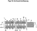
- an inventive expansion dowel 1 which comprises a dowel sleeve 2 and a collar 3.
- the dowel sleeve 2 extends in the axial direction along a longitudinal axis L from a front end 4 in the insertion direction E to a rear end 5, which is integrally connected to the collar 3.
- the collar 3 is in the radial direction r on the dowel sleeve 2 and serves as an abutment to rest on the anchoring ground in which the dowel sleeve is anchored in a borehole (not shown), which prevents the dowel sleeve 2 can be inserted deeper the hole, as planned.
- the dowel sleeve 2 comprises four paired arranged and axially parallel to the longitudinal axis L extending expansion webs 6a, 6b, 7a, 7b, which limit a receiving space 8 for a threaded member 9 in the radial direction r.
- the receiving space 8 is open at the rear end 5 of the dowel sleeve 2 in the direction of insertion E, such that the threaded element 9, in the exemplary embodiment a threaded rod with metric external thread, can be inserted into the receiving space 8 in the direction of insertion E.
- the receiving space 8 is bounded at its front end by a flat closed circular cover plate 10, which forms the front end 4 of the dowel sleeve 2.
- the Sp Schwarzstege 6a, 6b, 7a, 7b are arranged in pairs opposite one another, wherein two opposing first Sp Schwarzstege 6a, 6b spreading elements 11 which protrude into the receiving space 8 as parts of an external thread of the threaded element 9 corresponding internal thread as projections, while the other two opposite second expansion ribs 7a, 7b only in their front in the direction of insertion E sections have spreading portions 12 which are wedge-shaped, such that the distance between the second Sp Schwarzstege 7a, 7b to the longitudinal axis L in Insertion direction E of the threaded element 9 in the receiving space 8 decreases (see in particular FIG. 5 ).
- the first expansion webs 6a, 6b and the second expansion webs 7a, 7b are mutually offset in the circumferential direction U by 90 °. Adjacent in the circumferential direction U Sp Dr Drleyge 6a, 6b, 7a, 7b are connected approximately in the axial center of the expansion anchor 1 by four connecting webs, of which in the figures, only three connecting webs 13, 14, 15 are visible. Respectively two connecting webs 13, 14, 15, which project from one of the expanding webs 6a, 6b, 7a, 7b oppositely directed in and against the circumferential direction U, are axially offset from one another, so that their axial distance to the rear end 5 of the anchor sleeve 2 varies in size is.
- the axial offset of the connecting webs 13, 14, 15 allows the expansion dowel 1 in the region of the connecting webs 13, 14, 15 is stiffened by the connecting webs 13, 14, 15 in the radial direction, wherein the expansion dowel 1 by the offset anyway in the Connecting webs 13, 14, 15 can be radially compressed, so that the dowel sleeve 2 is movable in this area and can be adapted to a wall of a borehole.
- the radially outer ends of the second expansion webs 7a, 7b have in a non-spread state (not shown) a radial extent which is smaller than the radial extent of the first expansion webs 6a, 6b, so that the dowel sleeve 2 in the unexpanded state in the region of the second Sp Schwarzstege 7a, 7b has a smaller outer diameter than in the region of the first expansion webs 6a, 6b.
- This also improves the adaptability of the dowel sleeve 2 to the wall of a borehole and facilitates the insertion of the dowel sleeve 2 into a borehole.
- an expansion element 11 has a holding element 16 and a latching element 17.
- the holding element 16 is located radially on the outside of the expansion element 11 and serves to hold the dowel sleeve 2 in a borehole by frictionally holding the dowel sleeve 2 against a wall of a borehole.
- the holding element 16 is designed as a rib 18 a, which has at its front end a wedge surface 19, which facilitates insertion of the dowel sleeve 2 in a borehole.
- the rib 18a also has a groove-like weakening 20 running in the circumferential direction U, which divides the rib 18a into two lamellae 21, which are easily deformable and can adapt well to a borehole wall.
- the locking element 17 protrudes into the receiving space 8 for engagement in the external thread of the threaded element 9 and consists of three flanks 22 which form parts of an internal thread corresponding to the external thread of the threaded element 9.
- Each of the locking elements 17 of the spreading elements 11 has a
- the locking elements 17 at their the rear end 5 of the dowel sleeve 2 facing ends 23 are wedge-shaped, such that the distance of the locking element 17 to the longitudinal axis L. decreases in the insertion direction E of the threaded member 9 in the receiving space 8.
- the axial extension of the latching elements 17 is greater than the axial extent of the holding elements 16 associated with an expansion element 11, so that the latching element 17 begins in the axial direction in front of the holding element 16 and ends behind the holding element 16.
- the first spreading webs 6a, 6b six spaced apart in the axial direction of spreading elements 11 are arranged, wherein each of the second and the fifth expansion element 11, relative to the longitudinal axis L, not as far radially outward as the other spreading elements 11, what facilitates the introduction of the anchor sleeve 2 in a borehole. In the areas between the spreading elements 11, the first spreading webs 6a, 6b are reduced in thickness.
- the thickness of the first expanding webs 6a, 6b is less than in the region of the connecting webs 13, 14, 15, whereby the webs in the region of the spreading elements 11 are more flexible and movable and thus tilting of the spreading elements 11 during insertion of the threaded element 9 in facilitate the receiving space 8.
- the thickness of the first expanding webs 6a, 6b is also reduced, so that here a predetermined separation point 24 is formed at which the cover plate 10 can be separated from the first spreading webs 6a, 6b, if a user inserts the threaded element 9 too far and / or with too much force in the receiving space 8 or strikes, so that the first spreading webs 6a, 6b are not damaged in the region of the spreading elements 11.
- the second spreading webs 7a, 7b have a constant thickness over their axial length which is greater than the reduced thickness of the first spreading webs 6a, 6b.
- Ribs 18b which correspond in cross-section to the ribs 18a of the first spreading webs 6a, 6b, are likewise arranged on the second spreading webs 7a, 7b.
- the second spreading webs 7a, 7b have no latching elements, so that no spreading elements are present on the second spreading webs 7a, 7b.
- FIGS. 1 and 3 show the expansion anchor 1 with the receiving space 8 corresponding threaded element 9, which is planned in the receiving space 8 between the Sp Drardstege 6a, 6b, 7a, 7b introduced.
- FIG. 2a can be seen, meets the threaded element 9 when introduced into the receiving space 8 in the region of the spreading elements 11 first on the wedge-shaped rear end 23 of the locking element 17, whereby the spreader 11 substantially as a whole about a first tilt axis K first tilts in a first direction of rotation D 1 and a rear part of the holding member 16 is moved radially outward and pressed against a wall of a borehole.
Landscapes
- Engineering & Computer Science (AREA)
- General Engineering & Computer Science (AREA)
- Mechanical Engineering (AREA)
- Dowels (AREA)
- Joining Of Building Structures In Genera (AREA)
Abstract
Description
- Die Erfindung betrifft einen Spreizdübel mit den Merkmalen des Oberbegriffs des Anspruchs 1.
- Aus der Offenlegungsschrift
DE 10 2005 030 174 A1 ist ein gattungsgemäßer Spreizdübel bekannt. Der Spreizdübel weist eine Dübelhülse mit einem Aufnahmeraum auf, in den eine Gewindestange eingesteckt werden kann. Der Aufnahmeraum wird radial durch vier Spreizstege begrenzt, wobei an zwei gegenüberliegenden Spreizstegen plattenartige, zur Längsachse geneigte und kippbare Spreizelemente angeordnet sind. Die Spreizelemente bilden mit ihren radial äußeren Enden den äußeren Rand der Dübelhülse. Die äußeren Enden der Spreizelemente dienen als Halteelemente, die den Spreizdübel durch Druck gegen die Bohrlochwand in einem Bohrloch halten. Die radial inneren Enden der Spreizelemente ragen als Rastelemente in den Aufnahmeraum, wo sie Teile eines Innengewindes bilden. Wird eine Gewindestange in den Aufnahmeraum eingesteckt, so drückt die Gewindestange in Einbringrichtung gegen die Spreizelemente, die um eine Kippachse kippen, wodurch der Aufnahmeraum freigegeben wird, sodass die Gewindestange in den Aufnahmeraum eingeführt werden kann. Dabei rasten die Rastelemente in die Gewindegänge der Gewindestange ein. Wird nun die Gewindestange entgegen der Einbringrichtung zurückbewegt, beispielsweise durch Aufbringen einer äußeren Last auf die Gewindestange, so kippen die Spreizelemente zurück, wodurch die Halteelemente gegen eine Bohrlochwand gepresst werden und ein Herausziehen der Gewindestange aus der Spreizhülse und ein Herausziehen des Spreizdübels aus dem Bohrloch verhindert wird. - Obwohl der bekannte Spreizdübel bereits eine gute Funktion und Leistungsfähigkeit aufweist, ist es Aufgabe der Erfindung, einen gattungsgemäßen Spreizdübel mit verbessertem Spreizverhalten zu schaffen.
- Diese Aufgabe wird erfindungsgemäß durch einen Spreizdübel mit den Merkmalen des Anspruchs 1 gelöst.
- Der erfindungsgemäße Spreizdübel umfasst eine Dübelhülse, die sich in axialer Richtung entlang einer Längsachse des Spreizdübels erstreckt. Die Dübelhülse weist einen Aufnahmeraum auf, der an dem in Einbringrichtung hinteren Ende der Dübelhülse offen ist, so dass ein Gewindeelement in Einbringrichtung in den Aufnahmeraum eingesteckt werden kann. Mit "Einbringrichtung" ist hier die Richtung gemeint, in die ein Gewindeelement planmäßig bei der Montage des Spreizdübels in den Aufnahmeraum der Dübelhülse eingebracht wird, um das Gewindeelement in der Dübelhülse des Spreizdübels zu befestigen. Die Bezeichnungen "vorne" und "hinten" beziehen sich im Weiteren auf die Einbringrichtung. Dabei befindet sich die Dübelhülse im Regelfall in einem Bohrloch, das in einen Verankerungsgrund, beispielsweise einer Wand aus Beton, gebohrt wurde. Das Gewindeelement ist insbesondere eine Gewindestange oder eine Schraube, insbesondere mit metrischem Außengewinde. Um zu verhindern, dass der Spreizdübel beim Einbringen des Gewindeelements in den Aufnahmeraum unbeabsichtigt mit dem Gewindeelement in das Bohrloch hinein bewegt wird, weist der Spreizdübel insbesondere an seinem hinteren Ende einen Bund auf, der mit der Dübelhülse verbunden ist, und radial über den Umfang der Dübelhülse übersteht.
- Die Dübelhülse weist mindestens einen ersten Spreizsteg auf, der den Aufnahmeraum in radialer Richtung begrenzt und sich insbesondere in Längsrichtung des Spreizdübels erstreckt. Insbesondere ist der Aufnahmeraum durch mehrere, in Umfangsrichtung voneinander beabstandete und im Wesentlichen unabhängig voneinander in radialer Richtung bewegbare Spreizstege begrenzt. Die Spreizstege enden insbesondere jeweils an einer vorderen und einer hinteren Hülse des Spreizdübels. Insbesondere weist die Dübelhülse vier paarweise sich gegenüberliegende Spreizstege auf, wobei insbesondere sich gegenüberliegende Spreizstege den gleichen Querschnitt aufweisen. An dem mindestens einen Spreizsteg ist ein Spreizelement angeordnet, das radial außen ein Halteelement und radial innen ein Rastelement aufweist. Das Halteelement und das Rastelement ist jeweils ein radialer Vorsprung. Insbesondere bildet das Spreizelement mit seinem radial äußeren Ende, dem Halteelement, den radial äußeren Rand der Dübelhülse. Halteelement und/oder Rastelement können einstückig mit dem Spreizelement oder als Teile des Spreizelements ausgebildet sein. Das Spreizelement kann im Wesentlichen als Ganzes um eine Kippachse gegenüber der Längsachse gekippt werden. Die Kippachse liegt dabei im Wesentlichen in einer Radialebene zur Längsachse und ist insbesondere beabstandet zur Längsachse.
- Das Halteelement dient zum Halten der Dübelhülse in einem Bohrloch, insbesondere durch reibschlüssigen Kontakt mit der Wand des Bohrlochs. Das Rastelement dient zum Eingriff in ein Gewinde eines sich in dem Aufnahmeraum befindlichen Gewindeelements. "Rastelement" meint hier, dass ein Einführen eines Gewindeelements ohne Drehung in Einbringrichtung möglich ist und dabei das Rastelement in das Gewinde des Gewindeelements eingreift und zwar derart, dass es einem Herausziehen entgegen der Einbringrichtung entgegenwirkt. Hierzu ragt das Rastelement in den Aufnahmeraum. Sowohl das Halteelement als auch das Rastelement kann aus einem oder mehreren Teilen bestehen. Das Halteelement ist insbesondere als eine von der Dübelhülse radial nach außen abstehende Rippe ausgebildet, die insbesondere an ihrem in Einbringrichtung vorderen Ende keilförmig abgeschrägt ist, wodurch ein Einführen der Dübelhülse in ein Bohrloch erleichtert wird. Das Halteelement weist insbesondere eine nutartige Schwächung auf, die insbesondere in Umfangsrichtung verläuft, wodurch am Halteelement mehrere Lamellen ausgebildet sind, die, im Gegensatz zu einer massiv ausgebildeten Rippe, relativ leicht verformbar sind. Das Rastelement umfasst insbesondere mehrere radial nach innen abstehende Flanken, die Teile eines Innengewindes bilden, das zu einem Außengewinde des Gewindeelements korrespondiert.
- Um einen Spreizdübel zu schaffen, der in einem Bohrloch einen möglichst guten Halt findet, weist das Rastelement erfindungsgemäß einen kleineren Abstand zum hinteren Ende der Dübelhülse auf, als das Halteelement. Dies bewirkt, dass das Spreizelement beim Einführen eines zum Aufnahmeraum korrespondierenden Gewindeelements in den Aufnahmeraum so gekippt wird, dass zunächst der, bezogen auf die Kippachse hintere, der Einführöffnung zugewandte Teil des Spreizelements radial nach außen bewegt wird und erst beim weiteren Einführen des Gewindeelements in den Aufnahmeraum der vordere Teil des Spreizelements durch ein Zurückkippen ebenfalls radial nach außen bewegt und das Spreizelement als Ganzes gegen die Bohrlochwand gepresst wird. Durch dieses Vor- und Zurückkippen wird das Spreizelement als Ganzes radial nach außen bewegt, wobei sich das Halteelement aufgrund der Kippbewegungen gut an Unebenheiten der Bohrlochwand anpassen und gegebenenfalls in diese eingreifen kann, wodurch der Halt zwischen Halteelement und Bohrlochwand stark verbessert wird. Im Gegensatz zu dem aus dem Stand der Technik bekannten Spreizdübel wird das Spreizelement nicht erst beim Ziehen an dem Gewindeelement verstärkt gegen die Bohrlochwand gepresst, sondern bereits beim Einführen des Gewindeelements in den Aufnahmeraum.
- Vorzugsweise ist das Rastelement an seinem hinteren Ende, das dem hinteren Ende der Dübelhülse zugewandt ist, keilförmig, derart, dass der Abstand des Rastelements zur Längsachse in Einbringrichtung eines Gewindeelements in den Aufnahmeraum abnimmt. Sind mehrere Spreizelemente vorhanden, so ist insbesondere jedes der Rastelemente keilförmig. Mit "keilförmig" ist hier nicht zwingend eine geradlinige oder kontinuierliche Zunahme gemeint, auch wenn dies bevorzugt ist, sondern beispielsweise auch eine gekrümmte Form. Aufgrund dieser Ausgestaltung des Rastelements wird das Einführen des Gewindeelements in den Aufnahmeraum und das Kippen des Spreizelements beim Einführen des Gewindeelements erleichtert.
- Weiterhin ist bevorzugt, dass die axiale Erstreckung des Rastelements größer als die axiale Erstreckung des Halteelements ist. Aufgrund der aus den unterschiedlichen axialen Erstreckungen resultierenden Hebelarme von Halte- und Rastelement wird das Anpressen des Halteelements gegen die Bohrlochwand beim Einführen des Gewindeelements verbessert. Eine weitere Verbesserung ist möglich, wenn das Rastelement in axialer Richtung vor dem Halteelement beginnt und hinter dem Halteelement endet.
- Erfindungsgemäß sind an einem Spreizsteg insbesondere mehrere Spreizelemente in Längsrichtung hintereinander angeordnet. Insbesondere sind Spreizelemente, die in Längsrichtung hintereinander an einem Spreizsteg angeordnet sind, miteinander verbunden, insbesondere an den einander zugewandten Enden.
- Bei einer weiteren bevorzugten Ausgestaltungsform des erfindungsgemäßen Spreizdübels sind an einem Spreizsteg mindestens zwei in axialer Richtung voneinander beabstandete Spreizelemente angeordnet, und der die beiden Spreizelemente verbindende Teil des Spreizstegs weist zumindest abschnittsweise einen reduzierten Querschnitt, insbesondere eine in radialer Richtung reduzierte Dicke auf. Der Spreizsteg wird hierdurch leichter verformbar und der Widerstand des Spreizstegs gegen ein Kippen eines Spreizelements wird verringert.
- Weiterhin ist bevorzugt, dass an einem Spreizsteg mindestens zwei in axialer Richtung voneinander beabstandete Spreizelemente angeordnet sind, die in radialer Richtung unterschiedlich weit über die Längsachse überstehen. Dies erleichtert das Einführen der Spreizhülse des Spreizdübels in ein Bohrloch und gibt der Spreizhülse im Bohrloch genügend Beweglichkeit, um Unebenheiten der Wand des Bohrloches beim Einführen eines Gewindeelements in den Aufnahmeraum ausgleichen zu können, ohne dass der Widerstand, mit dem die Spreizelemente dem Gewindeelement beim Einbringen entgegenwirken, so groß wird, dass Spreizelemente beschädigt werden, beispielsweise indem Teile des Rastelements vom restlichen Spreizelement abscheren.
- Bei einer weiteren bevorzugten Ausgestaltungsform weist der Spreizdübel einen zweiten Spreizsteg auf, der in einem Spreizabschnitt, der sich insbesondere in einem vorderen, dem hinteren Ende der Dübelhülse abgewandten Bereich des Aufnahmeraums befindet, keilförmig ist, derart, dass der Abstand des Spreizstegs zur Längsachse in Einbringrichtung eines Gewindeelements in den Aufnahmeraum abnimmt. Insbesondere weist dieser Spreizsteg kein Spreizelement auf. Durch den keilförmigen Spreizabschnitt wird der zweite Spreizsteg zusätzlich radial nach außen gedrückt, wenn das Gewindeelement beim Einführen in den Aufnahmeraum in den Bereich des Spreizabschnitts gelangt, wodurch sich der Halt der Dübelhülse im Bohrloch weiter erhöht. Dabei verhindert das Zusammenwirken des Spreizelements des ersten Spreizstegs mit dem keilförmigen Spreizbereich, dass beim Aufbringen einer Zuglast auf das Gewindeelement das Gewindeelement aus dem keilförmigen Spreizbereich und die Dübelhülse aus dem Bohrloch herausgezogen wird. Dabei ist bevorzugt, dass die Dübelhülse in einem unverspreizten Zustand, also vor dem Einführen des Gewindeelements in den Aufnahmeraum, im Bereich des zweiten Spreizstegs einen kleineren Außendurchmesser aufweist als im Bereich des ersten Spreizstegs. Die Dübelhülse lässt sich aufgrund dieser Ausgestaltung auch in ein unebenes Bohrloch ohne großen Kraftaufwand einstecken, wobei durch die oben erwähnte Ausbildung des keilförmigen Spreizabschnitts nach dem Einführen des Gewindeelements auch der zweite Spreizsteg zum Halt der Spreizhülse im Bohrloch beiträgt. Insbesondere weist die Dübelhülse zwei erste Spreizstege und zwei zweite Spreizstege auf, die paarweise einander gegenüberliegend an der Dübelhülse angeordnet sind. Die Dübelhülse weist dann im unverspreizten Zustand im Bereich der beiden ersten Spreizstege einen größeren Durchmesser auf als im Bereich der beiden zweiten Spreizstege.
- Weist der erfindungsgemäße Spreizdübel mehrere Spreizstege auf, die in Umfangsrichtung voneinander beabstandet sind, so sind die Spreizstege vorzugsweise in Umfangsrichtung durch Verbindungsstege miteinander verbunden, wobei die Verbindungstege, die von einem Spreizsteg in entgegengesetzte Umfangsrichtungen abstehen, in Längsrichtung zueinander axial versetzt sind. Der Versatz ist insbesondere größer, als die axiale Erstreckung eines der Verbindungsstege. Der Versatz der Verbindungsstege verbessert die Verformbarkeit des Spreizdübels in Umfangsrichtung.
- Vorzugsweise weist der Spreizdübel an seinem in Einbringrichtung vorderen Ende eine Deckplatte auf, die den Aufnahmeraum an seinem vorderen Ende begrenzt. Die Deckplatte ist mit zumindest einem Spreizsteg über eine Solltrennstelle verbunden, sodass die Deckplatte vom Spreizsteg abgetrennt wird, wenn das Gewindeelement zu weit in den Aufnahmeraum eingeführt und zu stark gegen die Deckplatte gedrückt wird. Hierdurch wird verhindert, dass der Spreizdübel unkontrolliert an einer undefinierten Stelle versagt, beispielsweise in der Mitte eines Spreizstegs, was zu einem kompletten Versagen der Befestigungsanordnung von Spreizdübel und Gewindeelement führen würde. Die Deckplatte hat vor dem vollständigen Einführen des Gewindeelements eine stabilisierende Funktion für die Spreizhülse und verhindert, dass beim Einführen der Spreizhülse in ein Bohrloch eine größere Menge Bohrmehl oder Staub in den Aufnahmeraum gelangt, was ein Einführen des Gewindeelements in den Aufnahmeraum behindern würde. Nach dem Einführen der Dübelhülse in das Bohrloch und dem Einführen des Gewindeelements in den Aufnahmeraum kann die Deckplatte abgetrennt werden, ohne dass ein Spreizelement und/oder ein Spreizbereich eines Spreizstegs seine Wirkung verliert.
- Die Erfindung wird nachfolgend anhand eines in den Figuren dargestellten Ausführungsbeispiels näher erläutert.
- Es zeigen:
- Figur 1
- einen erfindungsgemäßen Spreizdübel mit eingeführtem Gewindeelement in einer Seitenansicht;
- Figur 2a
- eine vergrößerte Darstellung eines Spreizelements des Spreizdübels (Detail II der
Figur 1 ) beim Einführen eines Gewindeelements; - Figur 2b
- eine vergrößerte Darstellung des Spreizelements der
Figur 2a nach dem Einführen des Gewindeelements; - Figur 3
- eine gegenüber der
Figur 1 um 90° gedrehte Seitenansicht des Spreizdübels; - Figur 4
- eine Ansicht des erfindungsgemäßen Spreizdübels in Einbringrichtung in den Aufnahmeraum hinein; und
- Figur 5
- eine perspektivische Ansicht des erfindungsgemäßen Spreizdübels von hinten, also in Einbringrichtung gesehen.
- In den Figuren ist ein erfindungsgemäßer Spreizdübel 1 dargestellt, der eine Dübelhülse 2 und einen Bund 3 umfasst. Die Dübelhülse 2 erstreckt sich in axialer Richtung entlang einer Längsachse L von einem in Einbringrichtung E vorderen Ende 4 bis zu einem hinteren Ende 5, das mit dem Bund 3 einstückig verbunden ist. Der Bund 3 steht in radialer Richtung r über die Dübelhülse 2 über und dient als Widerlager zur Anlage am Verankerungsgrund, in dem die Dübelhülse in einem Bohrloch (nicht dargestellt) verankert wird, das verhindert, dass die Dübelhülse 2 tiefer das Bohrloch gesteckt werden kann, als dies planmäßig vorgesehen ist. Die Dübelhülse 2 umfasst vier paarweise angeordnete und sich axial parallel zur Längsachse L erstreckende Spreizstege 6a, 6b, 7a, 7b, die einen Aufnahmeraum 8 für ein Gewindeelement 9 in radialer Richtung r begrenzen. Der Aufnahmeraum 8 ist an dem in Einbringrichtung E hinteren Ende 5 der Dübelhülse 2 offen, derart, dass das Gewindeelement 9, im Ausführungsbeispiel eine Gewindestange mit metrischem Außengewinde, in Einbringrichtung E in den Aufnahmeraum 8 eingesteckt werden kann. Der Aufnahmeraum 8 wird an seinem vorderen Ende durch eine flächig geschlossene kreisförmige Deckplatte 10 begrenzt, die das vordere Ende 4 der Dübelhülse 2 bildet.
- Die Spreizstege 6a, 6b, 7a, 7b sind paarweise sich gegenüberliegend angeordnet, wobei zwei sich gegenüberliegende erste Spreizstege 6a, 6b Spreizelemente 11 aufweisen, die in den Aufnahmeraum 8 als Teile eines zum Außengewinde des Gewindeelements 9 korrespondierenden Innengewindes als Vorsprünge hineinragen, während die anderen zwei sich gegenüberliegenden zweiten Spreizstege 7a, 7b nur in ihren in Einbringrichtung E vorderen Abschnitten Spreizabschnitte 12 aufweisen, die keilförmig sind, derart, dass der Abstand der zweiten Spreizstege 7a, 7b zur Längsachse L in Einbringrichtung E des Gewindeelements 9 in den Aufnahmeraum 8 abnimmt (siehe insbesondere
Figur 5 ). Die ersten Spreizstege 6a, 6b und die zweiten Spreizstege 7a, 7b sind zueinander in Umfangsrichtung U um jeweils 90° versetzt angeordnet. In Umfangsrichtung U benachbarte Spreizstege 6a, 6b, 7a, 7b sind ungefähr in der axialen Mitte des Spreizdübels 1 durch vier Verbindungsstege verbunden, von denen in den Figuren nur drei Verbindungsstege 13, 14, 15 sichtbar sind. Jeweils zwei Verbindungsstege 13, 14, 15, die von einem der Spreizstege 6a, 6b, 7a, 7b einander entgegen gerichtet in und entgegen der Umfangsrichtung U abstehen, sind zueinander axial versetzt, sodass ihr axialer Abstand zum hinteren Ende 5 der Dübelhülse 2 verschieden groß ist. Der axiale Versatz der Verbindungsstege 13, 14, 15 ermöglicht, dass der Spreizdübel 1 im Bereich der Verbindungsstege 13, 14, 15 von den Verbindungsstegen 13, 14, 15 in radialer Richtung ausgesteift wird, wobei der Spreizdübel 1 durch den Versatz trotzdem im Bereich der Verbindungsstege 13, 14, 15 radial zusammengedrückt werden kann, so dass die Dübelhülse 2 auch in diesem Bereich beweglich ist und sich an eine Wand eines Bohrlochs anpassen kann. Die radial äußeren Enden der zweiten Spreizstege 7a, 7b weisen in einem ungespreizten Zustand (nicht dargestellt) eine radiale Ausdehnung auf, die kleiner als die radiale Ausdehnung der ersten Spreizstege 6a, 6b ist, sodass die Dübelhülse 2 im ungespreizten Zustand im Bereich der zweiten Spreizstege 7a, 7b einen kleineren Außendurchmesser aufweist als im Bereich der ersten Spreizstege 6a, 6b. Auch hierdurch wird die Anpassungsfähigkeit der Dübelhülse 2 an die Wand eines Bohrlochs verbessert und das Einführen der Dübelhülse 2 in ein Bohrloch vereinfacht. - An den ersten Spreizstegen 6a, 6b sind die Spreizelemente 11 angeordnet. Jeweils ein Spreizelement 11 weist ein Halteelement 16 und ein Rastelement 17 auf. Das Halteelement 16 befindet sich radial außen am Spreizelement 11 und dient zum Halten der Dübelhülse 2 in einem Bohrloch, indem es die Dübelhülse 2 reibschlüssig an einer Wand eines Bohrlochs hält. Das Halteelement 16 ist als Rippe 18a ausgeführt, die an ihrem vorderen Ende eine Keilfläche 19 aufweist, die ein Einführen der Dübelhülse 2 in ein Bohrloch erleichtert. Die Rippe 18a weist zudem eine in Umfangsrichtung U verlaufende nutartige Schwächung 20 auf, die die Rippe 18a in zwei Lamellen 21 unterteilt, die leicht verformbar sind und sich gut an eine Bohrlochwand anpassen können. Das Rastelement 17 ragt zum Eingriff in das Außengewinde des Gewindeelements 9 in den Aufnahmeraum 8 hinein und besteht aus drei Flanken 22, die Teile eines zum Außengewinde des Gewindeelements 9 korrespondierenden Innengewindes bilden. Jedes der Rastelemente 17 der Spreizelemente 11 weist einen kleineren Abstand zum hinteren Ende 5 der Dübelhülse 2 auf, als das Halteelement 16 des jeweiligen Spreizelements 11. Zudem sind die Rastelemente 17 an ihren dem hinteren Ende 5 der Dübelhülse 2 zugewandten Enden 23 keilförmig, derart, dass der Abstand des Rastelements 17 zur Längsachse L in Einbringrichtung E des Gewindeelements 9 in den Aufnahmeraum 8 abnimmt. Weiterhin ist die axiale Erstreckung der Rastelemente 17 größer als die axiale Erstreckung der zu einem Spreizelement 11 zugehörigen Halteelemente 16, sodass das Rastelement 17 in axialer Richtung vor dem Halteelement 16 beginnt und hinter dem Halteelement 16 endet. An den ersten Spreizstegen 6a, 6b sind jeweils sechs in axialer Richtung voneinander beabstandete Spreizelemente 11 angeordnet, wobei jeweils das zweite und das fünfte Spreizelement 11, bezogen auf die Längsachse L, nicht so weit radial nach außen steht, wie die anderen Spreizelemente 11, was das Einbringen der Dübelhülse 2 in ein Bohrloch erleichtert. In den Bereichen zwischen den Spreizelementen 11 sind die ersten Spreizstege 6a, 6b in ihrer Dicke reduziert. In diesem Bereich ist die Dicke der ersten Spreizstege 6a, 6b geringer, als im Bereich der Verbindungsstege 13, 14, 15, wodurch die Stege im Bereich der Spreizelemente 11 biegsamer und beweglicher sind und damit ein Kippen der Spreizelemente 11 beim Einführen des Gewindeelements 9 in den Aufnahmeraum 8 erleichtern. An der Verbindungsstelle zwischen der Deckplatte 10 und den ersten Spreizstegen 6a, 6b ist die Dicke der ersten Spreizstege 6a, 6b ebenfalls reduziert, so dass hier eine Solltrennstelle 24 entsteht, an der die Deckplatte 10 von den ersten Spreizstegen 6a, 6b abgetrennt werden kann, falls ein Anwender das Gewindeelement 9 zu weit und/oder mit zu viel Kraft in den Aufnahmeraum 8 einsteckt oder einschlägt, so dass die ersten Spreizstege 6a, 6b im Bereich der Spreizelemente 11 nicht beschädigt werden. Die zweiten Spreizstege 7a, 7b weisen über ihre axiale Länge eine konstante Dicke auf, die größer als die reduzierte Dicke der ersten Spreizstege 6a, 6b ist. An den zweiten Spreizstegen 7a, 7b sind ebenfalls Rippen 18b angeordnet, die im Querschnitt den Rippen 18a der ersten Spreizstege 6a, 6b entsprechen. Allerdings weisen die zweiten Spreizstege 7a, 7b keine Rastelemente auf, sodass an den zweiten Spreizstegen 7a, 7b keine Spreizelemente vorhanden sind.
- Die
Figuren 1 und3 zeigen den Spreizdübel 1 mit dem zum Aufnahmeraum 8 korrespondierenden Gewindeelement 9, das planmäßig in den Aufnahmeraum 8 zwischen die Spreizstege 6a, 6b, 7a, 7b eingebracht ist. Wie inFigur 2a zu sehen ist, trifft das Gewindeelement 9 beim Einbringen in den Aufnahmeraum 8 im Bereich der Spreizelemente 11 zunächst auf das keilförmige hintere Ende 23 des Rastelements 17, wodurch das Spreizelement 11 im Wesentlichen als Ganzes um eine erste Kippachse K1 in eine erste Drehrichtung D1 kippt und ein hinterer Teil des Halteelements 16 radial nach außen bewegt und gegen eine Wand eines Bohrlochs gepresst wird. Beim weiteren Einbringen des Gewindeelements 9 in den Aufnahmeraum 8 wird dann auch der in Einbringrichtung E vordere Teil des Halteelements 16 nach außen gepresst, wodurch das Spreizelement 11 um eine zweite Kippachse K2, die mit der ersten Kippachse K1 identisch sein kann, in eine zweite Drehrichtung D2, die der ersten Drehrichtung D1 im Wesentlichen entgegengesetzt ist, zurückkippt, sodass das gesamte Halteelement 16 flächig an der Bohrlochwand anliegt. Im vorderen Bereich des Aufnahmeraums 8 trifft das Gewindeelement 9 auf die beiden keilförmigen Spreizabschnitte 12, die in den Aufnahmeraum 8 ragen, wodurch die zweiten Spreizstege 7a, 7b radial nach außen, gegen eine nicht dargestellte Bohrlochwand, gespreizt werden. Die Kombination der kippbaren Spreizelemente 11 der ersten Spreizstege 6a, 6b mit den radial spreizenden Spreizabschnitten 12 der zweiten Spreizstege 7a, 7b, die erst am Ende des Einführens des Gewindeelements 9 in den Aufnahmeraum 8 gespreizt werden, führt zu einem sehr guten Halt der Dübelhülse 2 in einem Bohrloch. -
- 1
- Spreizdübel
- 2
- Dübelhülse
- 3
- Bund
- 4
- vorderes Ende der Dübelhülse 2
- 5
- hinteres Ende der Dübelhülse 2
- 6a, 6b
- erster Spreizsteg
- 7a, 7b
- zweiter Spreizsteg
- 8
- Aufnahmeraum
- 9
- Gewindeelement
- 10
- Deckplatte
- 11
- Spreizelement
- 12
- Spreizabschnitt
- 13
- erster Verbindungssteg
- 14
- zweiter Verbindungssteg
- 15
- dritter Verbindungssteg
- 16
- Halteelement
- 17
- Rastelement
- 18a
- Rippe der ersten Spreizstege 6a, 6b
- 18b
- Rippe der zweiten Spreizstege 7a, 7b
- 19
- Keilfläche der Rippe 18a, 18b
- 20
- nutartige Schwächung der Rippe 18a, 18b
- 21
- Lamelle der Rippe 18a, 18b
- 22
- Flanke des Rastelements 17
- 23
- hinteres Ende des Rastelements 17
- 24
- Solltrennstelle
- D1
- erste Drehrichtung
- D2
- zweite Drehrichtung
- E
- Einbringrichtung
- K1
- erste Kippachse
- K2
- zweite Kippachse
- L
- Längsachse
- r
- radiale Richtung
- U
- Umfangsrichtung
Claims (10)
- Spreizdübel (1) mit einer Dübelhülse (2), die sich in axialer Richtung entlang einer Längsachse (L) erstreckt und die einen Aufnahmeraum (8) aufweist, der an dem in Einbringrichtung (E) hinteren Ende (5) der Dübelhülse (2) offen ist, so dass ein Gewindeelement (9) in Einbringrichtung (E) in den Aufnahmeraum (8) eingesteckt werden kann, wobei die Dübelhülse (2) mindestens einen ersten Spreizsteg (6a, 6b) aufweist, der den Aufnahmeraum (8) in radialer Richtung (r) begrenzt und an dem mindestens ein Spreizelement (11) angeordnet ist, wobei das Spreizelement (11) ein Halteelement (16) zum Halten der Dübelhülse (2) in einem Bohrloch und ein Rastelement (17) aufweist, das zum Eingriff in ein Gewinde eines Gewindeelements (9) in den Aufnahmeraum (8) ragt, wobei das Spreizelement (11) im Wesentlichen als Ganzes um eine Kippachse (K) gegenüber der Längsachse (L) kippbar ist, die im Wesentlichen in einer Radialebene zur Längsachse (L) liegt, dadurch gekennzeichnet, dass das Rastelement (17) einen kleineren Abstand zum hinteren Ende (5) der Dübelhülse (2) aufweist, als das Halteelement (16).
- Spreizdübel nach Anspruch 1, dadurch gekennzeichnet, dass das Rastelement (17) an seinem dem hinteren Ende (5) der Dübelhülse (2) zugewandten Ende (23) keilförmig ist, derart, dass der Abstand des Rastelements (17) zur Längsachse (L) in Einbringrichtung (E) eines Gewindeelements (9) in den Aufnahmeraum (8) abnimmt.
- Spreizdübel nach Anspruch 1 oder Anspruch 2, dadurch gekennzeichnet, dass die axiale Erstreckung des Rastelements (17) größer als die axiale Erstreckung des Halteelements (16) ist.
- Spreizdübel nach einem der Ansprüche 1 bis 3, dadurch gekennzeichnet, dass das Rastelement (17) in axialer Richtung vor dem Halteelement (16) beginnt und hinter dem Halteelement (16) endet.
- Spreizdübel nach einem der Ansprüche 1 bis 4, dadurch gekennzeichnet, dass an einem Spreizsteg (6a, 6b) mindestens zwei in axialer Richtung voneinander beabstandete Spreizelemente (11) angeordnet sind, und der die Spreizelemente (11) verbindende Teil des Spreizstegs (6a, 6b) zumindest abschnittsweise einen reduzierten Querschnitt aufweist.
- Spreizdübel nach einem der Ansprüche 1 bis 5, dadurch gekennzeichnet, dass an einem Spreizsteg (6a, 6b) mindestens zwei in axialer Richtung voneinander beabstandete Spreizelemente (11) angeordnet sind, die in radialer Richtung (r) unterschiedlich weit über die Längsachse (L) überstehen.
- Spreizdübel nach einem der Ansprüche 1 bis 6, dadurch gekennzeichnet, dass der Spreizdübel (1) einen zweiten Spreizsteg (7a, 7b) aufweist, der in einem Spreizabschnitt (12) keilförmig ist, derart, dass der Abstand des Spreizstegs (7a, 7b) zur Längsachse (L) in Einbringrichtung (E) eines Gewindeelements (9) in den Aufnahmeraum (8) abnimmt.
- Spreizdübel nach Anspruch 7, dadurch gekennzeichnet, dass die Dübelhülse (2) im Bereich des zweiten Spreizstegs (7a, 7b) einen kleineren Außendurchmesser aufweist als im Bereich des ersten Spreizstegs (6a, 6b).
- Spreizdübel nach einem der Ansprüche 1 bis 8, dadurch gekennzeichnet, dass der Spreizdübel (1) mehrere Spreizstege (6a, 6b, 7a, 7b) aufweist, die in Umfangsrichtung (U) durch Verbindungsstege (13, 14, 15) verbunden sind, die zueinander axial versetzt sind.
- Spreizdübel nach einem der Ansprüche 1 bis 9, dadurch gekennzeichnet, dass der Spreizdübel (1) eine Deckplatte (10) aufweist, die den Aufnahmeraum (8) an seinem vorderen Ende begrenzt, und dass zumindest ein Spreizsteg (6a, 6b) über eine Solltrennstelle (24) mit der Deckplatte (10) verbunden ist.
Applications Claiming Priority (2)
| Application Number | Priority Date | Filing Date | Title |
|---|---|---|---|
| DE102017103051 | 2017-02-15 | ||
| DE102018102261.1A DE102018102261A1 (de) | 2017-02-15 | 2018-02-01 | Spreizdübel |
Publications (2)
| Publication Number | Publication Date |
|---|---|
| EP3364053A1 true EP3364053A1 (de) | 2018-08-22 |
| EP3364053B1 EP3364053B1 (de) | 2020-08-12 |
Family
ID=61157045
Family Applications (1)
| Application Number | Title | Priority Date | Filing Date |
|---|---|---|---|
| EP18154811.6A Not-in-force EP3364053B1 (de) | 2017-02-15 | 2018-02-02 | Spreizdübel |
Country Status (1)
| Country | Link |
|---|---|
| EP (1) | EP3364053B1 (de) |
Citations (3)
| Publication number | Priority date | Publication date | Assignee | Title |
|---|---|---|---|---|
| DE19903457A1 (de) * | 1999-01-28 | 2000-08-03 | Heinrich Hofsaes Gmbh & Co | Spreizmuffe |
| DE102005030174A1 (de) | 2005-06-29 | 2007-01-04 | Fischerwerke Artur Fischer Gmbh & Co. Kg | Spreizdübel |
| EP2251555A1 (de) * | 2009-04-29 | 2010-11-17 | Sonja Maria Bilz | Dübel |
-
2018
- 2018-02-02 EP EP18154811.6A patent/EP3364053B1/de not_active Not-in-force
Patent Citations (3)
| Publication number | Priority date | Publication date | Assignee | Title |
|---|---|---|---|---|
| DE19903457A1 (de) * | 1999-01-28 | 2000-08-03 | Heinrich Hofsaes Gmbh & Co | Spreizmuffe |
| DE102005030174A1 (de) | 2005-06-29 | 2007-01-04 | Fischerwerke Artur Fischer Gmbh & Co. Kg | Spreizdübel |
| EP2251555A1 (de) * | 2009-04-29 | 2010-11-17 | Sonja Maria Bilz | Dübel |
Also Published As
| Publication number | Publication date |
|---|---|
| EP3364053B1 (de) | 2020-08-12 |
Similar Documents
| Publication | Publication Date | Title |
|---|---|---|
| DE69721173T2 (de) | Ankerbolzen | |
| EP0574669B1 (de) | Spreizanker | |
| DE2901066C2 (de) | Spreizdübel | |
| WO2020173664A1 (de) | Spreizverbinder | |
| EP1239168A2 (de) | Spreizdübel | |
| WO2018001916A1 (de) | Spreizanker | |
| CH656190A5 (en) | Plastic dowel for wood screws | |
| EP2923092B1 (de) | Spreizdübel | |
| DE10134734A1 (de) | Spreizdübel | |
| DE3006480C2 (de) | ||
| DE4231313C2 (de) | Spreizdübel | |
| DE102014224561B3 (de) | Spannfutter | |
| DE102018102261A1 (de) | Spreizdübel | |
| EP3364053B1 (de) | Spreizdübel | |
| EP1141559B1 (de) | Spreizdübel | |
| DE3319902A1 (de) | Vorrichtung zum befestigen eines gegenstandes an einer wand od. dgl. | |
| EP2628963B1 (de) | Dämmstoffdübel | |
| EP3175129B1 (de) | Spreizdübel | |
| EP2894355B1 (de) | Mehrteiliger Dämmstoffanker mit Rastverschluss | |
| DE202020106135U1 (de) | Dübel und Befestigungssystem | |
| EP4402384B1 (de) | Spreizdübel | |
| DE20306091U1 (de) | Türdichtungsvorrichtung | |
| EP1749953A2 (de) | Klemmstift | |
| EP1896732A1 (de) | Spreizdübel | |
| DE4404698A1 (de) | Spreizdübel |
Legal Events
| Date | Code | Title | Description |
|---|---|---|---|
| PUAI | Public reference made under article 153(3) epc to a published international application that has entered the european phase |
Free format text: ORIGINAL CODE: 0009012 |
|
| STAA | Information on the status of an ep patent application or granted ep patent |
Free format text: STATUS: THE APPLICATION HAS BEEN PUBLISHED |
|
| AK | Designated contracting states |
Kind code of ref document: A1 Designated state(s): AL AT BE BG CH CY CZ DE DK EE ES FI FR GB GR HR HU IE IS IT LI LT LU LV MC MK MT NL NO PL PT RO RS SE SI SK SM TR |
|
| AX | Request for extension of the european patent |
Extension state: BA ME |
|
| STAA | Information on the status of an ep patent application or granted ep patent |
Free format text: STATUS: REQUEST FOR EXAMINATION WAS MADE |
|
| 17P | Request for examination filed |
Effective date: 20190111 |
|
| RBV | Designated contracting states (corrected) |
Designated state(s): AL AT BE BG CH CY CZ DE DK EE ES FI FR GB GR HR HU IE IS IT LI LT LU LV MC MK MT NL NO PL PT RO RS SE SI SK SM TR |
|
| STAA | Information on the status of an ep patent application or granted ep patent |
Free format text: STATUS: EXAMINATION IS IN PROGRESS |
|
| 17Q | First examination report despatched |
Effective date: 20190528 |
|
| GRAP | Despatch of communication of intention to grant a patent |
Free format text: ORIGINAL CODE: EPIDOSNIGR1 |
|
| STAA | Information on the status of an ep patent application or granted ep patent |
Free format text: STATUS: GRANT OF PATENT IS INTENDED |
|
| INTG | Intention to grant announced |
Effective date: 20200420 |
|
| GRAS | Grant fee paid |
Free format text: ORIGINAL CODE: EPIDOSNIGR3 |
|
| GRAA | (expected) grant |
Free format text: ORIGINAL CODE: 0009210 |
|
| STAA | Information on the status of an ep patent application or granted ep patent |
Free format text: STATUS: THE PATENT HAS BEEN GRANTED |
|
| AK | Designated contracting states |
Kind code of ref document: B1 Designated state(s): AL AT BE BG CH CY CZ DE DK EE ES FI FR GB GR HR HU IE IS IT LI LT LU LV MC MK MT NL NO PL PT RO RS SE SI SK SM TR |
|
| REG | Reference to a national code |
Ref country code: CH Ref legal event code: EP |
|
| REG | Reference to a national code |
Ref country code: DE Ref legal event code: R096 Ref document number: 502018002135 Country of ref document: DE |
|
| REG | Reference to a national code |
Ref country code: IE Ref legal event code: FG4D Free format text: LANGUAGE OF EP DOCUMENT: GERMAN |
|
| REG | Reference to a national code |
Ref country code: AT Ref legal event code: REF Ref document number: 1301827 Country of ref document: AT Kind code of ref document: T Effective date: 20200915 |
|
| REG | Reference to a national code |
Ref country code: LT Ref legal event code: MG4D |
|
| REG | Reference to a national code |
Ref country code: NL Ref legal event code: MP Effective date: 20200812 |
|
| PG25 | Lapsed in a contracting state [announced via postgrant information from national office to epo] |
Ref country code: BG Free format text: LAPSE BECAUSE OF FAILURE TO SUBMIT A TRANSLATION OF THE DESCRIPTION OR TO PAY THE FEE WITHIN THE PRESCRIBED TIME-LIMIT Effective date: 20201112 Ref country code: HR Free format text: LAPSE BECAUSE OF FAILURE TO SUBMIT A TRANSLATION OF THE DESCRIPTION OR TO PAY THE FEE WITHIN THE PRESCRIBED TIME-LIMIT Effective date: 20200812 Ref country code: FI Free format text: LAPSE BECAUSE OF FAILURE TO SUBMIT A TRANSLATION OF THE DESCRIPTION OR TO PAY THE FEE WITHIN THE PRESCRIBED TIME-LIMIT Effective date: 20200812 Ref country code: GR Free format text: LAPSE BECAUSE OF FAILURE TO SUBMIT A TRANSLATION OF THE DESCRIPTION OR TO PAY THE FEE WITHIN THE PRESCRIBED TIME-LIMIT Effective date: 20201113 Ref country code: SE Free format text: LAPSE BECAUSE OF FAILURE TO SUBMIT A TRANSLATION OF THE DESCRIPTION OR TO PAY THE FEE WITHIN THE PRESCRIBED TIME-LIMIT Effective date: 20200812 Ref country code: NO Free format text: LAPSE BECAUSE OF FAILURE TO SUBMIT A TRANSLATION OF THE DESCRIPTION OR TO PAY THE FEE WITHIN THE PRESCRIBED TIME-LIMIT Effective date: 20201112 Ref country code: LT Free format text: LAPSE BECAUSE OF FAILURE TO SUBMIT A TRANSLATION OF THE DESCRIPTION OR TO PAY THE FEE WITHIN THE PRESCRIBED TIME-LIMIT Effective date: 20200812 |
|
| PG25 | Lapsed in a contracting state [announced via postgrant information from national office to epo] |
Ref country code: IS Free format text: LAPSE BECAUSE OF FAILURE TO SUBMIT A TRANSLATION OF THE DESCRIPTION OR TO PAY THE FEE WITHIN THE PRESCRIBED TIME-LIMIT Effective date: 20201212 Ref country code: RS Free format text: LAPSE BECAUSE OF FAILURE TO SUBMIT A TRANSLATION OF THE DESCRIPTION OR TO PAY THE FEE WITHIN THE PRESCRIBED TIME-LIMIT Effective date: 20200812 Ref country code: LV Free format text: LAPSE BECAUSE OF FAILURE TO SUBMIT A TRANSLATION OF THE DESCRIPTION OR TO PAY THE FEE WITHIN THE PRESCRIBED TIME-LIMIT Effective date: 20200812 Ref country code: NL Free format text: LAPSE BECAUSE OF FAILURE TO SUBMIT A TRANSLATION OF THE DESCRIPTION OR TO PAY THE FEE WITHIN THE PRESCRIBED TIME-LIMIT Effective date: 20200812 Ref country code: PL Free format text: LAPSE BECAUSE OF FAILURE TO SUBMIT A TRANSLATION OF THE DESCRIPTION OR TO PAY THE FEE WITHIN THE PRESCRIBED TIME-LIMIT Effective date: 20200812 |
|
| PG25 | Lapsed in a contracting state [announced via postgrant information from national office to epo] |
Ref country code: EE Free format text: LAPSE BECAUSE OF FAILURE TO SUBMIT A TRANSLATION OF THE DESCRIPTION OR TO PAY THE FEE WITHIN THE PRESCRIBED TIME-LIMIT Effective date: 20200812 Ref country code: DK Free format text: LAPSE BECAUSE OF FAILURE TO SUBMIT A TRANSLATION OF THE DESCRIPTION OR TO PAY THE FEE WITHIN THE PRESCRIBED TIME-LIMIT Effective date: 20200812 Ref country code: CZ Free format text: LAPSE BECAUSE OF FAILURE TO SUBMIT A TRANSLATION OF THE DESCRIPTION OR TO PAY THE FEE WITHIN THE PRESCRIBED TIME-LIMIT Effective date: 20200812 Ref country code: RO Free format text: LAPSE BECAUSE OF FAILURE TO SUBMIT A TRANSLATION OF THE DESCRIPTION OR TO PAY THE FEE WITHIN THE PRESCRIBED TIME-LIMIT Effective date: 20200812 Ref country code: SM Free format text: LAPSE BECAUSE OF FAILURE TO SUBMIT A TRANSLATION OF THE DESCRIPTION OR TO PAY THE FEE WITHIN THE PRESCRIBED TIME-LIMIT Effective date: 20200812 |
|
| REG | Reference to a national code |
Ref country code: DE Ref legal event code: R097 Ref document number: 502018002135 Country of ref document: DE |
|
| PG25 | Lapsed in a contracting state [announced via postgrant information from national office to epo] |
Ref country code: AL Free format text: LAPSE BECAUSE OF FAILURE TO SUBMIT A TRANSLATION OF THE DESCRIPTION OR TO PAY THE FEE WITHIN THE PRESCRIBED TIME-LIMIT Effective date: 20200812 |
|
| REG | Reference to a national code |
Ref country code: ES Ref legal event code: FG2A Ref document number: 2831003 Country of ref document: ES Kind code of ref document: T3 Effective date: 20210607 |
|
| PLBE | No opposition filed within time limit |
Free format text: ORIGINAL CODE: 0009261 |
|
| STAA | Information on the status of an ep patent application or granted ep patent |
Free format text: STATUS: NO OPPOSITION FILED WITHIN TIME LIMIT |
|
| PG25 | Lapsed in a contracting state [announced via postgrant information from national office to epo] |
Ref country code: SK Free format text: LAPSE BECAUSE OF FAILURE TO SUBMIT A TRANSLATION OF THE DESCRIPTION OR TO PAY THE FEE WITHIN THE PRESCRIBED TIME-LIMIT Effective date: 20200812 |
|
| 26N | No opposition filed |
Effective date: 20210514 |
|
| PG25 | Lapsed in a contracting state [announced via postgrant information from national office to epo] |
Ref country code: SI Free format text: LAPSE BECAUSE OF FAILURE TO SUBMIT A TRANSLATION OF THE DESCRIPTION OR TO PAY THE FEE WITHIN THE PRESCRIBED TIME-LIMIT Effective date: 20200812 |
|
| PG25 | Lapsed in a contracting state [announced via postgrant information from national office to epo] |
Ref country code: MC Free format text: LAPSE BECAUSE OF FAILURE TO SUBMIT A TRANSLATION OF THE DESCRIPTION OR TO PAY THE FEE WITHIN THE PRESCRIBED TIME-LIMIT Effective date: 20200812 |
|
| REG | Reference to a national code |
Ref country code: BE Ref legal event code: MM Effective date: 20210228 |
|
| PG25 | Lapsed in a contracting state [announced via postgrant information from national office to epo] |
Ref country code: CH Free format text: LAPSE BECAUSE OF NON-PAYMENT OF DUE FEES Effective date: 20210228 Ref country code: LU Free format text: LAPSE BECAUSE OF NON-PAYMENT OF DUE FEES Effective date: 20210202 Ref country code: LI Free format text: LAPSE BECAUSE OF NON-PAYMENT OF DUE FEES Effective date: 20210228 |
|
| PG25 | Lapsed in a contracting state [announced via postgrant information from national office to epo] |
Ref country code: IE Free format text: LAPSE BECAUSE OF NON-PAYMENT OF DUE FEES Effective date: 20210202 |
|
| PG25 | Lapsed in a contracting state [announced via postgrant information from national office to epo] |
Ref country code: BE Free format text: LAPSE BECAUSE OF NON-PAYMENT OF DUE FEES Effective date: 20210228 |
|
| GBPC | Gb: european patent ceased through non-payment of renewal fee |
Effective date: 20220202 |
|
| PG25 | Lapsed in a contracting state [announced via postgrant information from national office to epo] |
Ref country code: GB Free format text: LAPSE BECAUSE OF NON-PAYMENT OF DUE FEES Effective date: 20220202 |
|
| PG25 | Lapsed in a contracting state [announced via postgrant information from national office to epo] |
Ref country code: PT Free format text: LAPSE BECAUSE OF FAILURE TO SUBMIT A TRANSLATION OF THE DESCRIPTION OR TO PAY THE FEE WITHIN THE PRESCRIBED TIME-LIMIT Effective date: 20201214 |
|
| PG25 | Lapsed in a contracting state [announced via postgrant information from national office to epo] |
Ref country code: CY Free format text: LAPSE BECAUSE OF FAILURE TO SUBMIT A TRANSLATION OF THE DESCRIPTION OR TO PAY THE FEE WITHIN THE PRESCRIBED TIME-LIMIT Effective date: 20200812 |
|
| PG25 | Lapsed in a contracting state [announced via postgrant information from national office to epo] |
Ref country code: HU Free format text: LAPSE BECAUSE OF FAILURE TO SUBMIT A TRANSLATION OF THE DESCRIPTION OR TO PAY THE FEE WITHIN THE PRESCRIBED TIME-LIMIT; INVALID AB INITIO Effective date: 20180202 |
|
| REG | Reference to a national code |
Ref country code: AT Ref legal event code: MM01 Ref document number: 1301827 Country of ref document: AT Kind code of ref document: T Effective date: 20230202 |
|
| PGFP | Annual fee paid to national office [announced via postgrant information from national office to epo] |
Ref country code: ES Payment date: 20240326 Year of fee payment: 7 |
|
| PG25 | Lapsed in a contracting state [announced via postgrant information from national office to epo] |
Ref country code: AT Free format text: LAPSE BECAUSE OF NON-PAYMENT OF DUE FEES Effective date: 20230202 |
|
| PG25 | Lapsed in a contracting state [announced via postgrant information from national office to epo] |
Ref country code: MK Free format text: LAPSE BECAUSE OF FAILURE TO SUBMIT A TRANSLATION OF THE DESCRIPTION OR TO PAY THE FEE WITHIN THE PRESCRIBED TIME-LIMIT Effective date: 20200812 Ref country code: AT Free format text: LAPSE BECAUSE OF NON-PAYMENT OF DUE FEES Effective date: 20230202 |
|
| PGFP | Annual fee paid to national office [announced via postgrant information from national office to epo] |
Ref country code: DE Payment date: 20240110 Year of fee payment: 7 |
|
| PGFP | Annual fee paid to national office [announced via postgrant information from national office to epo] |
Ref country code: IT Payment date: 20240228 Year of fee payment: 7 Ref country code: FR Payment date: 20240221 Year of fee payment: 7 |
|
| PG25 | Lapsed in a contracting state [announced via postgrant information from national office to epo] |
Ref country code: MT Free format text: LAPSE BECAUSE OF FAILURE TO SUBMIT A TRANSLATION OF THE DESCRIPTION OR TO PAY THE FEE WITHIN THE PRESCRIBED TIME-LIMIT Effective date: 20200812 |
|
| REG | Reference to a national code |
Ref country code: DE Ref legal event code: R119 Ref document number: 502018002135 Country of ref document: DE |
|
| PG25 | Lapsed in a contracting state [announced via postgrant information from national office to epo] |
Ref country code: TR Free format text: LAPSE BECAUSE OF FAILURE TO SUBMIT A TRANSLATION OF THE DESCRIPTION OR TO PAY THE FEE WITHIN THE PRESCRIBED TIME-LIMIT Effective date: 20200812 |
|
| PG25 | Lapsed in a contracting state [announced via postgrant information from national office to epo] |
Ref country code: DE Free format text: LAPSE BECAUSE OF NON-PAYMENT OF DUE FEES Effective date: 20250902 |
|
| PG25 | Lapsed in a contracting state [announced via postgrant information from national office to epo] |
Ref country code: FR Free format text: LAPSE BECAUSE OF NON-PAYMENT OF DUE FEES Effective date: 20250228 Ref country code: IT Free format text: LAPSE BECAUSE OF NON-PAYMENT OF DUE FEES Effective date: 20250202 |
|
| REG | Reference to a national code |
Ref country code: ES Ref legal event code: FD2A Effective date: 20260326 |
|
| PG25 | Lapsed in a contracting state [announced via postgrant information from national office to epo] |
Ref country code: ES Free format text: LAPSE BECAUSE OF NON-PAYMENT OF DUE FEES Effective date: 20250203 |
|
| PGFP | Annual fee paid to national office [announced via postgrant information from national office to epo] |
Ref country code: AT Payment date: 20260410 Year of fee payment: 5 |