EP3363993A1 - Fan and corresponding gas turbine engine - Google Patents
Fan and corresponding gas turbine engine Download PDFInfo
- Publication number
- EP3363993A1 EP3363993A1 EP18152885.2A EP18152885A EP3363993A1 EP 3363993 A1 EP3363993 A1 EP 3363993A1 EP 18152885 A EP18152885 A EP 18152885A EP 3363993 A1 EP3363993 A1 EP 3363993A1
- Authority
- EP
- European Patent Office
- Prior art keywords
- fan
- blade
- blades
- root
- retention feature
- Prior art date
- Legal status (The legal status is an assumption and is not a legal conclusion. Google has not performed a legal analysis and makes no representation as to the accuracy of the status listed.)
- Granted
Links
Images

Classifications
-
- F—MECHANICAL ENGINEERING; LIGHTING; HEATING; WEAPONS; BLASTING
- F01—MACHINES OR ENGINES IN GENERAL; ENGINE PLANTS IN GENERAL; STEAM ENGINES
- F01D—NON-POSITIVE DISPLACEMENT MACHINES OR ENGINES, e.g. STEAM TURBINES
- F01D5/00—Blades; Blade-carrying members; Heating, heat-insulating, cooling or antivibration means on the blades or the members
- F01D5/02—Blade-carrying members, e.g. rotors
- F01D5/10—Anti- vibration means
-
- F—MECHANICAL ENGINEERING; LIGHTING; HEATING; WEAPONS; BLASTING
- F04—POSITIVE - DISPLACEMENT MACHINES FOR LIQUIDS; PUMPS FOR LIQUIDS OR ELASTIC FLUIDS
- F04D—NON-POSITIVE-DISPLACEMENT PUMPS
- F04D29/00—Details, component parts, or accessories
- F04D29/26—Rotors specially for elastic fluids
- F04D29/32—Rotors specially for elastic fluids for axial flow pumps
- F04D29/34—Blade mountings
-
- F—MECHANICAL ENGINEERING; LIGHTING; HEATING; WEAPONS; BLASTING
- F01—MACHINES OR ENGINES IN GENERAL; ENGINE PLANTS IN GENERAL; STEAM ENGINES
- F01D—NON-POSITIVE DISPLACEMENT MACHINES OR ENGINES, e.g. STEAM TURBINES
- F01D5/00—Blades; Blade-carrying members; Heating, heat-insulating, cooling or antivibration means on the blades or the members
- F01D5/12—Blades
- F01D5/14—Form or construction
- F01D5/16—Form or construction for counteracting blade vibration
-
- F—MECHANICAL ENGINEERING; LIGHTING; HEATING; WEAPONS; BLASTING
- F01—MACHINES OR ENGINES IN GENERAL; ENGINE PLANTS IN GENERAL; STEAM ENGINES
- F01D—NON-POSITIVE DISPLACEMENT MACHINES OR ENGINES, e.g. STEAM TURBINES
- F01D5/00—Blades; Blade-carrying members; Heating, heat-insulating, cooling or antivibration means on the blades or the members
- F01D5/30—Fixing blades to rotors; Blade roots ; Blade spacers
- F01D5/3007—Fixing blades to rotors; Blade roots ; Blade spacers of axial insertion type
-
- F—MECHANICAL ENGINEERING; LIGHTING; HEATING; WEAPONS; BLASTING
- F01—MACHINES OR ENGINES IN GENERAL; ENGINE PLANTS IN GENERAL; STEAM ENGINES
- F01D—NON-POSITIVE DISPLACEMENT MACHINES OR ENGINES, e.g. STEAM TURBINES
- F01D5/00—Blades; Blade-carrying members; Heating, heat-insulating, cooling or antivibration means on the blades or the members
- F01D5/30—Fixing blades to rotors; Blade roots ; Blade spacers
- F01D5/32—Locking, e.g. by final locking blades or keys
- F01D5/323—Locking of axial insertion type blades by means of a key or the like parallel to the axis of the rotor
-
- F—MECHANICAL ENGINEERING; LIGHTING; HEATING; WEAPONS; BLASTING
- F01—MACHINES OR ENGINES IN GENERAL; ENGINE PLANTS IN GENERAL; STEAM ENGINES
- F01D—NON-POSITIVE DISPLACEMENT MACHINES OR ENGINES, e.g. STEAM TURBINES
- F01D5/00—Blades; Blade-carrying members; Heating, heat-insulating, cooling or antivibration means on the blades or the members
- F01D5/30—Fixing blades to rotors; Blade roots ; Blade spacers
- F01D5/32—Locking, e.g. by final locking blades or keys
- F01D5/326—Locking of axial insertion type blades by other means
-
- F—MECHANICAL ENGINEERING; LIGHTING; HEATING; WEAPONS; BLASTING
- F02—COMBUSTION ENGINES; HOT-GAS OR COMBUSTION-PRODUCT ENGINE PLANTS
- F02K—JET-PROPULSION PLANTS
- F02K3/00—Plants including a gas turbine driving a compressor or a ducted fan
- F02K3/02—Plants including a gas turbine driving a compressor or a ducted fan in which part of the working fluid by-passes the turbine and combustion chamber
- F02K3/04—Plants including a gas turbine driving a compressor or a ducted fan in which part of the working fluid by-passes the turbine and combustion chamber the plant including ducted fans, i.e. fans with high volume, low pressure outputs, for augmenting the jet thrust, e.g. of double-flow type
- F02K3/06—Plants including a gas turbine driving a compressor or a ducted fan in which part of the working fluid by-passes the turbine and combustion chamber the plant including ducted fans, i.e. fans with high volume, low pressure outputs, for augmenting the jet thrust, e.g. of double-flow type with front fan
-
- F—MECHANICAL ENGINEERING; LIGHTING; HEATING; WEAPONS; BLASTING
- F04—POSITIVE - DISPLACEMENT MACHINES FOR LIQUIDS; PUMPS FOR LIQUIDS OR ELASTIC FLUIDS
- F04D—NON-POSITIVE-DISPLACEMENT PUMPS
- F04D29/00—Details, component parts, or accessories
- F04D29/26—Rotors specially for elastic fluids
- F04D29/32—Rotors specially for elastic fluids for axial flow pumps
- F04D29/325—Rotors specially for elastic fluids for axial flow pumps for axial flow fans
- F04D29/327—Rotors specially for elastic fluids for axial flow pumps for axial flow fans with non identical blades
-
- F—MECHANICAL ENGINEERING; LIGHTING; HEATING; WEAPONS; BLASTING
- F04—POSITIVE - DISPLACEMENT MACHINES FOR LIQUIDS; PUMPS FOR LIQUIDS OR ELASTIC FLUIDS
- F04D—NON-POSITIVE-DISPLACEMENT PUMPS
- F04D29/00—Details, component parts, or accessories
- F04D29/66—Combating cavitation, whirls, noise, vibration or the like; Balancing
- F04D29/661—Combating cavitation, whirls, noise, vibration or the like; Balancing especially adapted for elastic fluid pumps
- F04D29/666—Combating cavitation, whirls, noise, vibration or the like; Balancing especially adapted for elastic fluid pumps by means of rotor construction or layout, e.g. unequal distribution of blades or vanes
-
- F—MECHANICAL ENGINEERING; LIGHTING; HEATING; WEAPONS; BLASTING
- F04—POSITIVE - DISPLACEMENT MACHINES FOR LIQUIDS; PUMPS FOR LIQUIDS OR ELASTIC FLUIDS
- F04D—NON-POSITIVE-DISPLACEMENT PUMPS
- F04D29/00—Details, component parts, or accessories
- F04D29/66—Combating cavitation, whirls, noise, vibration or the like; Balancing
- F04D29/661—Combating cavitation, whirls, noise, vibration or the like; Balancing especially adapted for elastic fluid pumps
- F04D29/668—Combating cavitation, whirls, noise, vibration or the like; Balancing especially adapted for elastic fluid pumps damping or preventing mechanical vibrations
-
- F—MECHANICAL ENGINEERING; LIGHTING; HEATING; WEAPONS; BLASTING
- F05—INDEXING SCHEMES RELATING TO ENGINES OR PUMPS IN VARIOUS SUBCLASSES OF CLASSES F01-F04
- F05D—INDEXING SCHEME FOR ASPECTS RELATING TO NON-POSITIVE-DISPLACEMENT MACHINES OR ENGINES, GAS-TURBINES OR JET-PROPULSION PLANTS
- F05D2220/00—Application
- F05D2220/30—Application in turbines
- F05D2220/32—Application in turbines in gas turbines
-
- F—MECHANICAL ENGINEERING; LIGHTING; HEATING; WEAPONS; BLASTING
- F05—INDEXING SCHEMES RELATING TO ENGINES OR PUMPS IN VARIOUS SUBCLASSES OF CLASSES F01-F04
- F05D—INDEXING SCHEME FOR ASPECTS RELATING TO NON-POSITIVE-DISPLACEMENT MACHINES OR ENGINES, GAS-TURBINES OR JET-PROPULSION PLANTS
- F05D2220/00—Application
- F05D2220/30—Application in turbines
- F05D2220/36—Application in turbines specially adapted for the fan of turbofan engines
-
- F—MECHANICAL ENGINEERING; LIGHTING; HEATING; WEAPONS; BLASTING
- F05—INDEXING SCHEMES RELATING TO ENGINES OR PUMPS IN VARIOUS SUBCLASSES OF CLASSES F01-F04
- F05D—INDEXING SCHEME FOR ASPECTS RELATING TO NON-POSITIVE-DISPLACEMENT MACHINES OR ENGINES, GAS-TURBINES OR JET-PROPULSION PLANTS
- F05D2240/00—Components
- F05D2240/90—Mounting on supporting structures or systems
-
- F—MECHANICAL ENGINEERING; LIGHTING; HEATING; WEAPONS; BLASTING
- F05—INDEXING SCHEMES RELATING TO ENGINES OR PUMPS IN VARIOUS SUBCLASSES OF CLASSES F01-F04
- F05D—INDEXING SCHEME FOR ASPECTS RELATING TO NON-POSITIVE-DISPLACEMENT MACHINES OR ENGINES, GAS-TURBINES OR JET-PROPULSION PLANTS
- F05D2260/00—Function
- F05D2260/30—Retaining components in desired mutual position
-
- F—MECHANICAL ENGINEERING; LIGHTING; HEATING; WEAPONS; BLASTING
- F05—INDEXING SCHEMES RELATING TO ENGINES OR PUMPS IN VARIOUS SUBCLASSES OF CLASSES F01-F04
- F05D—INDEXING SCHEME FOR ASPECTS RELATING TO NON-POSITIVE-DISPLACEMENT MACHINES OR ENGINES, GAS-TURBINES OR JET-PROPULSION PLANTS
- F05D2260/00—Function
- F05D2260/96—Preventing, counteracting or reducing vibration or noise
-
- F—MECHANICAL ENGINEERING; LIGHTING; HEATING; WEAPONS; BLASTING
- F05—INDEXING SCHEMES RELATING TO ENGINES OR PUMPS IN VARIOUS SUBCLASSES OF CLASSES F01-F04
- F05D—INDEXING SCHEME FOR ASPECTS RELATING TO NON-POSITIVE-DISPLACEMENT MACHINES OR ENGINES, GAS-TURBINES OR JET-PROPULSION PLANTS
- F05D2260/00—Function
- F05D2260/96—Preventing, counteracting or reducing vibration or noise
- F05D2260/961—Preventing, counteracting or reducing vibration or noise by mistuning rotor blades or stator vanes with irregular interblade spacing, airfoil shape
Definitions
- the present disclosure concerns a fan for a gas turbine engine and/or a gas turbine engine.
- Gas turbine engines are typically employed to power aircraft.
- a gas turbine engine will comprise an axial fan driven by an engine core.
- the engine core is generally made up of one or more turbines which drive respective compressors via coaxial shafts.
- the fan is usually driven off an additional lower pressure turbine in the engine core.
- the fan includes a plurality of fan blades arranged around a disc.
- the blades may be integrally formed with the disc or the blades and disc may be formed separately, and a blade root of the blades may be received in a complimentary slot in the disc.
- the blade root and slot of the disc may have any suitable shape, but are often dovetail shaped.
- a fan for a gas turbine engine comprising a first set of fan blades.
- Each fan blade of the first set comprises a root and an axial retention feature provided on the root at a first position.
- the fan further comprises a second set of fan blades.
- Each fan blade of the second set comprises a root and an axial retention feature provided on the root at a second position. Relative to the respective blade on which the respective retention feature is provided, the first position is different to the second position.
- the first position may be at a different relative chordal position to the second position.
- the first position may be proximal to a leading edge of the respective fan blade.
- the second position may be proximal to a trailing edge of the respective fan blade.
- One of the first or second positions may be provided on a pressure side of the respective blade and the other of the second or first position may be provided on the suction side of the respective blade.
- a plurality of retention features may be provided on each blade. At least one of the retention features may be on a pressure side of the respective blade and at least one of the retention features may be provided on a suction side of the respective blade.
- the first set of fan blades may comprise two retention features provided on a pressure side of the blade and one retention feature provided on a suction side of the blade.
- the second set of fan blades may comprise two retention features provided on a suction side of the blade and one retention feature provided on a pressure side of the blade.
- One of the two retention features provided on the pressure side of each of the blades of the first set of blades may be provided proximal to the leading edge and the other may be provided proximal to the trailing edge.
- One retention feature provided on the suction side of the blade may be provided in a mid-region between the leading and trailing edge of the blade.
- One of the two retention features that may be provided on the suction side of each of the blades of the second set of blades may be provided proximal to the leading edge and the other may be provided proximal to the trailing edge.
- One retention feature provided on the pressure side of the blade may be provided in a mid-region between the leading and trailing edge of the blade.
- the retention feature provided in the mid-region may be provided mid-way between the leading edge and the trailing edge.
- the first set of fan blades and the second set of fan blades may be arranged to alternate circumferentially around the fan.
- the fan blades may be mounted to a disc via a disc slot and the disc slot may comprise a circumferentially extending groove.
- the retention feature may be an integrally formed protrusion provided on the root of the respective blade, and the protrusion may be received in a groove of a respective disc slot.
- the protrusion may protrude from a flank of the blade root.
- the protrusions may extend in a chordwise direction by approximately 5 to 10% of the length of the blade root.
- the protrusion may have a substantially rectangular cross section with rounded corners.
- the axial retention feature of the first set of blades may be a different size or shape to the axial retention feature of the second set of blades.
- the retention features of the first set of blades may have a different volume or mass (e.g. a larger volume or mass) than the retention feature of the second set of blades.
- the chordal length of the protrusion on the first set of blades may be different to the chordal length of the protrusion on the second set of blades.
- the axial retention feature of the first set of blades may be larger than the axial retention features of the second set of blades.
- a fan for a gas turbine engine comprising a first set of fan blades, each of the fan blades of the first set comprising an axial retention feature proximal to a leading edge of the fan blade.
- the fan further comprising a second set of fan blades, each of the fan blades of the second set comprising an axial retention feature proximal to a trailing edge of the fan blade.
- the fan may comprise one or more features of the fan of the previous aspect.
- a fan for a gas turbine engine comprising a first set of fan blades, each of the fan blades of the first set comprising one or more retention features on a pressure side and a suction side of a root of the blade, and wherein more retention features are provided on the pressure side than on the suction side of the blades of the first set.
- the fan further comprising a second set of fan blades, each of the fan blades of the second set comprising one or more retention features on a pressure side and a suction side of a root of the blade, and wherein more retention features are provided on the suction side than on the pressure side of the blades of the second set.
- the fan may comprise one or more features of the fan of the previous aspect.
- a gas turbine engine comprising the fan according to any one of the previous aspects.
- a gas turbine engine is generally indicated at 10, having a principal and rotational axis 11.
- the engine 10 comprises, in axial flow series, an air intake 12, a propulsive fan 13, an intermediate pressure compressor 14, a high-pressure compressor 15, combustion equipment 16, a high-pressure turbine 17, an intermediate pressure turbine 18, a low-pressure turbine 19 and an exhaust nozzle 20.
- a nacelle 21 generally surrounds the engine 10 and defines both the intake 12 and the exhaust nozzle 20.
- the gas turbine engine 10 works in the conventional manner so that air entering the intake 12 is accelerated by the fan 13 to produce two air flows: a first air flow into the intermediate pressure compressor 14 and a second air flow which passes through a bypass duct 22 to provide propulsive thrust.
- the intermediate pressure compressor 14 compresses the airflow directed into it before delivering that air to the high pressure compressor 15 where further compression takes place.
- the compressed air exhausted from the high-pressure compressor 15 is directed into the combustion equipment 16 where it is mixed with fuel and the mixture combusted.
- the resultant hot combustion products then expand through, and thereby drive the high, intermediate and low-pressure turbines 17, 18, 19 before being exhausted through the nozzle 20 to provide additional propulsive thrust.
- the high 17, intermediate 18 and low 19 pressure turbines drive respectively the high pressure compressor 15, intermediate pressure compressor 14 and fan 13, each by suitable interconnecting shaft.
- gas turbine engines to which the present disclosure may be applied may have alternative configurations.
- such engines may have an alternative number of interconnecting shafts (e.g. two) and/or an alternative number of compressors and/or turbines.
- the engine may comprise a gearbox provided in the drive train from a turbine to a compressor and/or fan.
- the fan 13 includes a plurality of fan blades 22 extending from a disc, which may also be considered to be a hub.
- the fan blade includes a tip 24, a root 26, a leading edge 28, a trailing edge 30, a pressure surface 32 on a pressure side of the blade and a suction surface 33 on a suction side of the blade.
- Three directions are defined relative to the blade: a spanwise direction S which extends in a direction from the root to the tip of the blade; a chordwise direction C which extends in a direction from a leading edge to a trailing edge of the blade; and a thickness direction T which extends in a direction from the pressure surface to the suction surface of the blade.
- the fan disc 34 includes an axially (or chordwise) extending slot 36.
- the slot is dovetail shaped, but may be any suitable shape.
- the disc also includes a groove 38.
- the groove 38 extends circumferentially from and away from the slot 36 of the disc.
- the groove is substantially rectangular in cross section. In the present example the groove is provided proximal to a forward-most position of the fan disc, but generally the groove is provided at a position that corresponds to a retention feature on the blade root that will now be described.
- the fan blade root 26 may be dove tailed in shape.
- the shape and size of the fan blade root is complimentary to the shape and size of the slot 36 of the disc 34.
- a retention feature, and in this example an integral retention feature is provided on the blade root.
- the integral retention feature is a projection 44 that is formed integrally with the fan blade root.
- the retention feature is provided on a flank 46 of the fan blade root and extends to a section 48 of the blade root that extends in a substantially spanwise (and chordwise) direction.
- the projection 44 is substantially rectangular in cross section and includes rounded edges.
- the transition between the remainder of the root and the projection may define a curved surface. In this way, there are no sharp corners between the projection and the remainder of the fan blade root.
- the projection extends approximately 5 to 10 % of the chordwise length of the fan blade root. However, the projection may extend any suitable length.
- the disc 34 may be formed roughly to shape and size, e.g. by forging, and then the disc may be machined to the desired dimensions and to include the desired features. During this machining process the slots 36 and the grooves 38 can be formed in the disc. The disc can then be post-processed, for example treated for compressive strength using a technique such as deep cold rolling.
- the blade root 26 may be machined from solid, and the projection 44 may be defined during this machining process.
- the blade root and projection may then be post-processed to improve compressive strength.
- the blade root and projection may be deep cold rolled.
- the fan blade is assembled in a similar manner to that described in relation to the blade and disc of US544336 which is incorporated herein by reference, but without the need to assemble a retention arrangement to the fan blade root.
- the fan blade root 26 is received in the fan disc slot 36.
- the projections 44 are such that they do not interfere with the sides of the fan disc slot whilst the fan blade root is slid into place in the slot of the disc.
- a spring member and slider similar to that shown in US544336 is then used to bias the fan blade root radially outwardly, such that the projections 44 are received in the respective grooves 38 of the fan disc 34.
- flutter is an aeroelastic instability occurring generally as a non-integral order vibration.
- the positioning and/or shape and/or size of the retention feature can be selected to reduce flutter.
- the present disclosure proposes providing a fan with at least two different sets of fan blades, each set of fan blades having a different arrangement of retention features.
- the retention features are projections 150 and 152, similar to the projection 44 previously described.
- Figure 5 illustrates the root of a blade from a first set of fan blades.
- the blades from the first set of fan blades include a projection 150 provided proximal to the leading edge of the fan blade.
- the projection 150 is chordally proximal to but spaced from the leading edge.
- the projection 150 extends on both the pressure side and the suction side of the blade, similar to the previously described example.
- Figure 6 illustrates the root of a blade from a second set of fan blades that has an arrangement of retention feature(s) different to the first set of fan blades.
- the blades from the second set of fan blades include a projection 152 provided proximal to the trailing edge of the fan blade.
- the projection 152 is chordally proximal to but spaced from the trailing edge.
- the projection 152 extends on both the pressure side and the suction side of the blade, similar to the previously described example.
- the projection 150 provided proximal to the leading edge of the first set of blades has a greater chordal length than the projection 152 provided proximal to the trailing edge of the second set of fan blades.
- Provision of a larger projection 150 proximal to the leading edge can increase the vibration strain energy and reduce the kinetic energy in the region near the leading edge and the root, so as to reduce the 1 F mode frequency.
- the blades of the first set and the second set are alternated, such that one blade of the second set is provided between two blades of the first set, circumferentially around the fan.
- the difference in root configuration, i.e. the different position and size of the projections 150, 152 will mistune the fan. This mistuning can be designed to improve flutter stability of the fan.
- the fan includes a first set of blades with retention features in a first set of locations and a second set of blades with retention features in a second set of locations.
- the first set of blades includes two projections 250a, 250b on a pressure side of the root 226 of the blade and one projection 250c on the suction side of the root. In this example, only two projections are provided on the pressure side and only one projection is provided on the suction side of the root.
- one of the projections 250a on the pressure side of the root 226 is provided proximal to the leading edge of the blade.
- the projection 250a is chordally spaced from a position aligned with the leading edge of the blade.
- the other projection 250b on the pressure side of the root 226 is provided proximal to the trailing edge of the blade.
- the projection 250b is chordally spaced from a position aligned with the trailing edge of the blade.
- the projection 250c is provided at a chordal position between that of the two projections on the suction side of the root, and projection 250c may be considered to be provided at a mid-position or in a mid-region of the blade root.
- the projections 250a, 250b, 250c are all dimensioned and shaped the same, but in alternative embodiments the dimensions and shape of the projections may be varied.
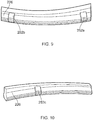
- the second set of blades includes two projections 252a, 252b on a suction side of the root 226 of the blade and one projection 252c on the pressure side of the root.
- the second set of blades includes two projections 252a, 252b on a suction side of the root 226 of the blade and one projection 252c on the pressure side of the root.
- only two projections are provided on the suction side and only one projection is provided on the pressure side of the root.
- one of the projections 252a on the suction side of the root 226 is provided proximal to the leading edge of the blade.
- the projection 252a is chordally spaced from a position aligned with the leading edge of the blade.
- the other projection 252b on the suction side of the root 226 is provided proximal to the trailing edge of the blade.
- the projection 252b is chordally spaced from a position aligned with the trailing edge of the blade.
- the projection 252c is provided at a chordal position between that of the two projections on the pressure side of the root, and projection 252c may be considered to be provided at a mid-position or in a mid-region of the blade root.
- the projection 252c is provided nearer the leading edge than the trailing edge.
- the projections 252a, 252b, 252c are all dimensioned and shaped the same, but in alternative embodiments the dimensions and shape of the projections may be varied.
- Adding different shapes, sizes and/or number of retention features and/or providing the retention features in different locations can result in different contact pressures at the blade root of the first set of blades compared to the blade root of the second set of blades. This difference in contact pressures can modify the blade to disc interface or friction damping for the first set compared to the second set.
- the different blade to disc interfaces can result in mistuning which can contribute to improving flutter stability.
- the fan has been described as including two different sets of blades, but it may include three or more different sets of blades, each set having blades with a different arrangement of retention features, e.g. a different distribution of retention features or retention features provided at different chordal locations.
- the fan has been described as having an alternating distribution of fan blades such that circumferentially one fan blade from the first set is adjacent a fan blade of the second set in a suction side and a pressure side direction (or in both a clockwise and anti-clockwise direction), and one fan blade from the second set is adjacent a fan blade of the first set in a suction side and a pressure side direction (or in both a clockwise and anti-clockwise direction).
- an alternative distribution of fan blades may be provided, for example two or more fan blades of the first set may be circumferentially adjacent to each other, and/or two or more fan blades of the second set may be circumferentially adjacent to each other.
- the described examples provide exemplary positions of the retention features and/or of the shape and/or size and/or type of retention features, but in alternative embodiments the retention features may be in a different position, have a different shape, be a different size, and/or be a different type of retention feature.
- the retention feature may be a groove for accommodating a shear key. The shear key may then engage with the groove in the slot.
- one or more of the sets of blades may have a groove in the root for a shear key and the one or more of the other sets of blades may include a protrusion (i.e. an integral shear key).
Landscapes
- Engineering & Computer Science (AREA)
- Mechanical Engineering (AREA)
- General Engineering & Computer Science (AREA)
- Chemical & Material Sciences (AREA)
- Combustion & Propulsion (AREA)
- Structures Of Non-Positive Displacement Pumps (AREA)
Abstract
Description
- The present disclosure concerns a fan for a gas turbine engine and/or a gas turbine engine.
- Gas turbine engines are typically employed to power aircraft. Typically a gas turbine engine will comprise an axial fan driven by an engine core. The engine core is generally made up of one or more turbines which drive respective compressors via coaxial shafts. The fan is usually driven off an additional lower pressure turbine in the engine core.
- The fan includes a plurality of fan blades arranged around a disc. The blades may be integrally formed with the disc or the blades and disc may be formed separately, and a blade root of the blades may be received in a complimentary slot in the disc. The blade root and slot of the disc may have any suitable shape, but are often dovetail shaped.
- Engagement of the slot and the root of the blade retains the fan blade in position with respect to the disc in a radial and circumferential direction. However, to retain the fan blade in an axial direction an additional retention arrangement is needed. An example of such a retention arrangement, that can also transfer loads to the disc in extreme events such as bird strike or foreign object impact, is explained in detail in
US544336 which is incorporated herein by reference. - According to an aspect there is provided a fan for a gas turbine engine, the fan comprising a first set of fan blades. Each fan blade of the first set comprises a root and an axial retention feature provided on the root at a first position. The fan further comprises a second set of fan blades. Each fan blade of the second set comprises a root and an axial retention feature provided on the root at a second position. Relative to the respective blade on which the respective retention feature is provided, the first position is different to the second position.
- The first position may be at a different relative chordal position to the second position.
- The first position may be proximal to a leading edge of the respective fan blade. The second position may be proximal to a trailing edge of the respective fan blade.
- One of the first or second positions may be provided on a pressure side of the respective blade and the other of the second or first position may be provided on the suction side of the respective blade.
- A plurality of retention features may be provided on each blade. At least one of the retention features may be on a pressure side of the respective blade and at least one of the retention features may be provided on a suction side of the respective blade.
- The first set of fan blades may comprise two retention features provided on a pressure side of the blade and one retention feature provided on a suction side of the blade. The second set of fan blades may comprise two retention features provided on a suction side of the blade and one retention feature provided on a pressure side of the blade.
- One of the two retention features provided on the pressure side of each of the blades of the first set of blades may be provided proximal to the leading edge and the other may be provided proximal to the trailing edge. One retention feature provided on the suction side of the blade may be provided in a mid-region between the leading and trailing edge of the blade. One of the two retention features that may be provided on the suction side of each of the blades of the second set of blades may be provided proximal to the leading edge and the other may be provided proximal to the trailing edge. One retention feature provided on the pressure side of the blade may be provided in a mid-region between the leading and trailing edge of the blade.
- The retention feature provided in the mid-region may be provided mid-way between the leading edge and the trailing edge.
- The first set of fan blades and the second set of fan blades may be arranged to alternate circumferentially around the fan.
- The fan blades may be mounted to a disc via a disc slot and the disc slot may comprise a circumferentially extending groove. The retention feature may be an integrally formed protrusion provided on the root of the respective blade, and the protrusion may be received in a groove of a respective disc slot.
- The protrusion may protrude from a flank of the blade root.
- The protrusions may extend in a chordwise direction by approximately 5 to 10% of the length of the blade root.
- The protrusion may have a substantially rectangular cross section with rounded corners.
- The axial retention feature of the first set of blades may be a different size or shape to the axial retention feature of the second set of blades. For example, the retention features of the first set of blades may have a different volume or mass (e.g. a larger volume or mass) than the retention feature of the second set of blades. For example, when the retention feature is a protrusion, the chordal length of the protrusion on the first set of blades may be different to the chordal length of the protrusion on the second set of blades.
- The axial retention feature of the first set of blades may be larger than the axial retention features of the second set of blades.
- According to an aspect there is provided a fan for a gas turbine engine, the fan comprising a first set of fan blades, each of the fan blades of the first set comprising an axial retention feature proximal to a leading edge of the fan blade. The fan further comprising a second set of fan blades, each of the fan blades of the second set comprising an axial retention feature proximal to a trailing edge of the fan blade.
- The fan may comprise one or more features of the fan of the previous aspect.
- According to an aspect there is provided a fan for a gas turbine engine, the fan comprising a first set of fan blades, each of the fan blades of the first set comprising one or more retention features on a pressure side and a suction side of a root of the blade, and wherein more retention features are provided on the pressure side than on the suction side of the blades of the first set. The fan further comprising a second set of fan blades, each of the fan blades of the second set comprising one or more retention features on a pressure side and a suction side of a root of the blade, and wherein more retention features are provided on the suction side than on the pressure side of the blades of the second set.
- The fan may comprise one or more features of the fan of the previous aspect.
- According to an aspect there is provided a gas turbine engine comprising the fan according to any one of the previous aspects.
- The skilled person will appreciate that except where mutually exclusive, a feature described in relation to any one of the above aspects may be applied mutatis mutandis to any other aspect. Furthermore except where mutually exclusive any feature described herein may be applied to any aspect and/or combined with any other feature described herein.
- Embodiments will now be described by way of example only, with reference to the Figures, in which:
-
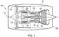
Figure 1 is a sectional side view of a gas turbine engine; -
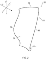
Figure 2 is a schematic perspective view of a fan blade; -
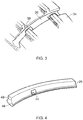
Figure 3 is a perspective view of a slot on a disc of a fan; -
Figure 4 is a perspective view of a root of a fan blade; -
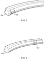
Figure 5 is a perspective view of a root of a fan blade of a first set of fan blades; -
Figure 6 is a perspective view of a root of a fan blade of a second set of fan blades; -
Figures 7 and 8 are perspective views of an alternative root of a first set of fan blades; and -
Figures 9 and 10 are perspective views of an alternative root of a second set of fan blades. - With reference to
Figure 1 , a gas turbine engine is generally indicated at 10, having a principal androtational axis 11. Theengine 10 comprises, in axial flow series, anair intake 12, apropulsive fan 13, anintermediate pressure compressor 14, a high-pressure compressor 15,combustion equipment 16, a high-pressure turbine 17, anintermediate pressure turbine 18, a low-pressure turbine 19 and anexhaust nozzle 20. Anacelle 21 generally surrounds theengine 10 and defines both theintake 12 and theexhaust nozzle 20. - The
gas turbine engine 10 works in the conventional manner so that air entering theintake 12 is accelerated by thefan 13 to produce two air flows: a first air flow into theintermediate pressure compressor 14 and a second air flow which passes through abypass duct 22 to provide propulsive thrust. Theintermediate pressure compressor 14 compresses the airflow directed into it before delivering that air to thehigh pressure compressor 15 where further compression takes place. - The compressed air exhausted from the high-
pressure compressor 15 is directed into thecombustion equipment 16 where it is mixed with fuel and the mixture combusted. The resultant hot combustion products then expand through, and thereby drive the high, intermediate and low-pressure turbines nozzle 20 to provide additional propulsive thrust. The high 17, intermediate 18 and low 19 pressure turbines drive respectively thehigh pressure compressor 15,intermediate pressure compressor 14 andfan 13, each by suitable interconnecting shaft. - Other gas turbine engines to which the present disclosure may be applied may have alternative configurations. By way of example such engines may have an alternative number of interconnecting shafts (e.g. two) and/or an alternative number of compressors and/or turbines. Further the engine may comprise a gearbox provided in the drive train from a turbine to a compressor and/or fan.
- The
fan 13 includes a plurality offan blades 22 extending from a disc, which may also be considered to be a hub. Referring toFigure 2 , the fan blade includes atip 24, aroot 26, a leadingedge 28, a trailingedge 30, apressure surface 32 on a pressure side of the blade and asuction surface 33 on a suction side of the blade. Three directions are defined relative to the blade: a spanwise direction S which extends in a direction from the root to the tip of the blade; a chordwise direction C which extends in a direction from a leading edge to a trailing edge of the blade; and a thickness direction T which extends in a direction from the pressure surface to the suction surface of the blade. - Referring to
Figure 3 , thefan disc 34 includes an axially (or chordwise) extendingslot 36. In the present example, the slot is dovetail shaped, but may be any suitable shape. The disc also includes agroove 38. Thegroove 38 extends circumferentially from and away from theslot 36 of the disc. The groove is substantially rectangular in cross section. In the present example the groove is provided proximal to a forward-most position of the fan disc, but generally the groove is provided at a position that corresponds to a retention feature on the blade root that will now be described. - Referring to
Figure 4 , thefan blade root 26 may be dove tailed in shape. The shape and size of the fan blade root is complimentary to the shape and size of theslot 36 of thedisc 34. A retention feature, and in this example an integral retention feature is provided on the blade root. The integral retention feature is aprojection 44 that is formed integrally with the fan blade root. The retention feature is provided on aflank 46 of the fan blade root and extends to asection 48 of the blade root that extends in a substantially spanwise (and chordwise) direction. - The
projection 44 is substantially rectangular in cross section and includes rounded edges. The transition between the remainder of the root and the projection may define a curved surface. In this way, there are no sharp corners between the projection and the remainder of the fan blade root. In the present example, the projection extends approximately 5 to 10 % of the chordwise length of the fan blade root. However, the projection may extend any suitable length. - In
Figure 4 , only one projection is shown (i.e. the projection on the pressure side of the blade), but a further projection is provided on the opposite side of the fan blade (i.e. on the suction side of the blade). The projection on the opposite side of the fan blade is provided at the same chordwise position as the projection shown inFigure 4 . Both projections also have the same shape and size. The groove in the disc ofFigure 3 is provided at a location that is aligned with the projection when the blade root is in the disc slot. - Referring to
Figures 3 and 4 , thedisc 34 may be formed roughly to shape and size, e.g. by forging, and then the disc may be machined to the desired dimensions and to include the desired features. During this machining process theslots 36 and thegrooves 38 can be formed in the disc. The disc can then be post-processed, for example treated for compressive strength using a technique such as deep cold rolling. - The
blade root 26 may be machined from solid, and theprojection 44 may be defined during this machining process. The blade root and projection may then be post-processed to improve compressive strength. For example, the blade root and projection may be deep cold rolled. - In use, the fan blade is assembled in a similar manner to that described in relation to the blade and disc of
US544336 which is incorporated herein by reference, but without the need to assemble a retention arrangement to the fan blade root. Thefan blade root 26 is received in thefan disc slot 36. Theprojections 44 are such that they do not interfere with the sides of the fan disc slot whilst the fan blade root is slid into place in the slot of the disc. A spring member and slider, similar to that shown inUS544336 is then used to bias the fan blade root radially outwardly, such that theprojections 44 are received in therespective grooves 38 of thefan disc 34. - Gas turbine engines are designed to avoid vibratory failures. The most common types of vibration problems include resonant vibration and flutter. As the person of ordinary skill in the art will recognise, flutter is an aeroelastic instability occurring generally as a non-integral order vibration. In the following described examples, the positioning and/or shape and/or size of the retention feature can be selected to reduce flutter.
- To reduce flutter, the present disclosure proposes providing a fan with at least two different sets of fan blades, each set of fan blades having a different arrangement of retention features.
- Referring now to
Figures 5 and 6 , in a first example of such a fan, the retention features areprojections projection 44 previously described.Figure 5 illustrates the root of a blade from a first set of fan blades. The blades from the first set of fan blades include aprojection 150 provided proximal to the leading edge of the fan blade. In this example, theprojection 150 is chordally proximal to but spaced from the leading edge. In this example, theprojection 150 extends on both the pressure side and the suction side of the blade, similar to the previously described example. -
Figure 6 illustrates the root of a blade from a second set of fan blades that has an arrangement of retention feature(s) different to the first set of fan blades. The blades from the second set of fan blades include aprojection 152 provided proximal to the trailing edge of the fan blade. In this example, theprojection 152 is chordally proximal to but spaced from the trailing edge. In this example, theprojection 152 extends on both the pressure side and the suction side of the blade, similar to the previously described example. - The
projection 150 provided proximal to the leading edge of the first set of blades has a greater chordal length than theprojection 152 provided proximal to the trailing edge of the second set of fan blades. - Provision of a
larger projection 150 proximal to the leading edge can increase the vibration strain energy and reduce the kinetic energy in the region near the leading edge and the root, so as to reduce the 1 F mode frequency. - The blades of the first set and the second set are alternated, such that one blade of the second set is provided between two blades of the first set, circumferentially around the fan. The difference in root configuration, i.e. the different position and size of the
projections - A further example of how fan blades can be designed and arranged to improve flutter stability will now be described with reference to
Figures 7 to 10 . - The fan includes a first set of blades with retention features in a first set of locations and a second set of blades with retention features in a second set of locations. Referring to
Figures 7 and 8 , the first set of blades includes twoprojections root 226 of the blade and oneprojection 250c on the suction side of the root. In this example, only two projections are provided on the pressure side and only one projection is provided on the suction side of the root. - Referring to
Figure 7 , one of theprojections 250a on the pressure side of theroot 226 is provided proximal to the leading edge of the blade. In this example, theprojection 250a is chordally spaced from a position aligned with the leading edge of the blade. Theother projection 250b on the pressure side of theroot 226 is provided proximal to the trailing edge of the blade. In this example theprojection 250b is chordally spaced from a position aligned with the trailing edge of the blade. Referring toFigure 8 , theprojection 250c is provided at a chordal position between that of the two projections on the suction side of the root, andprojection 250c may be considered to be provided at a mid-position or in a mid-region of the blade root. In the present example, theprojections - Referring to
Figures 9 and 10 , the second set of blades includes twoprojections root 226 of the blade and oneprojection 252c on the pressure side of the root. In this example, only two projections are provided on the suction side and only one projection is provided on the pressure side of the root. - Referring to
Figure 9 , one of theprojections 252a on the suction side of theroot 226 is provided proximal to the leading edge of the blade. In this example, theprojection 252a is chordally spaced from a position aligned with the leading edge of the blade. Theother projection 252b on the suction side of theroot 226 is provided proximal to the trailing edge of the blade. In this example theprojection 252b is chordally spaced from a position aligned with the trailing edge of the blade. Referring toFigure 10 , theprojection 252c is provided at a chordal position between that of the two projections on the pressure side of the root, andprojection 252c may be considered to be provided at a mid-position or in a mid-region of the blade root. In this example, theprojection 252c is provided nearer the leading edge than the trailing edge. In the present example, theprojections - Adding different shapes, sizes and/or number of retention features and/or providing the retention features in different locations, can result in different contact pressures at the blade root of the first set of blades compared to the blade root of the second set of blades. This difference in contact pressures can modify the blade to disc interface or friction damping for the first set compared to the second set. The different blade to disc interfaces can result in mistuning which can contribute to improving flutter stability.
- The fan has been described as including two different sets of blades, but it may include three or more different sets of blades, each set having blades with a different arrangement of retention features, e.g. a different distribution of retention features or retention features provided at different chordal locations.
- The fan has been described as having an alternating distribution of fan blades such that circumferentially one fan blade from the first set is adjacent a fan blade of the second set in a suction side and a pressure side direction (or in both a clockwise and anti-clockwise direction), and one fan blade from the second set is adjacent a fan blade of the first set in a suction side and a pressure side direction (or in both a clockwise and anti-clockwise direction). However, in alternative embodiments, an alternative distribution of fan blades may be provided, for example two or more fan blades of the first set may be circumferentially adjacent to each other, and/or two or more fan blades of the second set may be circumferentially adjacent to each other.
- It will be appreciated that the described examples provide exemplary positions of the retention features and/or of the shape and/or size and/or type of retention features, but in alternative embodiments the retention features may be in a different position, have a different shape, be a different size, and/or be a different type of retention feature. For example, in alternative embodiments, the retention feature may be a groove for accommodating a shear key. The shear key may then engage with the groove in the slot. In further examples, one or more of the sets of blades may have a groove in the root for a shear key and the one or more of the other sets of blades may include a protrusion (i.e. an integral shear key).
- It will be understood that the invention is not limited to the embodiments above-described and various modifications and improvements can be made without departing from the concepts described herein. Except where mutually exclusive, any of the features may be employed separately or in combination with any other features and the disclosure extends to and includes all combinations and subcombinations of one or more features described herein.
Claims (12)
- A fan for a gas turbine engine, the fan comprising:a first set of fan blades, each fan blade of the first set comprising a root and an axial retention feature provided on the root at a first position; anda second set of fan blades, each fan blade of the second set comprising a root and an axial retention feature provided on the root at a second position;wherein relative to the respective blade on which the respective retention feature is provided, the first position is different to the second position.
- The fan according to claim 1, wherein the first position is at a different relative chordal position to the second position.
- The fan according to claim 1 or 2, wherein the first position is proximal to a leading edge of the respective fan blade, and the second position is proximal to a trailing edge of the respective fan blade.
- The fan according to any one of the previous claims, wherein one of the first or second positions is provided on a pressure side of the respective blade and the other of the second or first position is provided on the suction side of the respective blade.
- The fan according to claim 4, wherein a plurality of retention features are provided on each blade, and at least one of the retention features is on a pressure side of the respective blade and at least one of the retention features is provided on a suction side of the respective blade.
- The fan according to claim 5, wherein the first set of fan blades comprises two retention features provided on a pressure side of the blade and one retention feature provided on a suction side of the blade, and wherein the second set of fan blades comprises two retention features provided on a suction side of the blade and one retention feature provided on a pressure side of the blade.
- The fan according to claim 6, wherein one of the two retention features provided on the pressure side of each of the blades of the first set of blades is provided proximal to the leading edge and the other is provided proximal to the trailing edge, and the one retention feature provided on the suction side of the blade is provided in a mid-region between the leading and trailing edge of the blade; and
wherein one of the two retention features provided on the suction side of each of the blades of the second set of blades is provided proximal to the leading edge and the other is provided proximal to the trailing edge, and the one retention feature provided on the pressure side of the blade is provided in a mid-region between the leading and trailing edge of the blade. - The fan according to any one of the previous claims, wherein the first set of fan blades and the second set of fan blades are arranged to alternate circumferentially around the fan.
- The fan according to any one of the previous claims, wherein the fan blades are mounted to a disc via a disc slot comprising a groove, and wherein the retention feature is an integrally formed protrusion provided on the root of the respective blade, and the protrusion is received in the groove of the respective disc slot.
- The fan according to any one of the previous claims, wherein the axial retention feature of the first set of blades is larger than the axial retention features of the second set of blades.
- The fan according to claim 10 as dependent on claim 9, wherein the chordal length of the protrusion is longer on the first set of blades than on the second set of blades.
- A gas turbine engine comprising the fan according to any one of the previous claims.
Applications Claiming Priority (1)
| Application Number | Priority Date | Filing Date | Title |
|---|---|---|---|
| GR20170100075 | 2017-02-20 |
Publications (2)
| Publication Number | Publication Date |
|---|---|
| EP3363993A1 true EP3363993A1 (en) | 2018-08-22 |
| EP3363993B1 EP3363993B1 (en) | 2021-03-10 |
Family
ID=58687930
Family Applications (1)
| Application Number | Title | Priority Date | Filing Date |
|---|---|---|---|
| EP18152885.2A Active EP3363993B1 (en) | 2017-02-20 | 2018-01-23 | Fan and corresponding gas turbine engine |
Country Status (3)
| Country | Link |
|---|---|
| US (1) | US10724536B2 (en) |
| EP (1) | EP3363993B1 (en) |
| GB (1) | GB201704832D0 (en) |
Cited By (1)
| Publication number | Priority date | Publication date | Assignee | Title |
|---|---|---|---|---|
| FR3144849A1 (en) * | 2023-01-05 | 2024-07-12 | Safran Aircraft Engines | FAN ROTOR ASSEMBLY FOR TURBOMACHINE |
Families Citing this family (2)
| Publication number | Priority date | Publication date | Assignee | Title |
|---|---|---|---|---|
| JP7064076B2 (en) * | 2018-03-27 | 2022-05-10 | 三菱重工業株式会社 | How to tune turbine blades, turbines, and natural frequencies of turbine blades |
| US11255219B2 (en) * | 2018-06-11 | 2022-02-22 | General Electric Company | System and method for turbomachinery blade diagnostics via discrete markings |
Citations (5)
| Publication number | Priority date | Publication date | Assignee | Title |
|---|---|---|---|---|
| US544336A (en) | 1895-08-13 | Disintegrator or crusher | ||
| US3400912A (en) * | 1967-08-16 | 1968-09-10 | United Aircraft Corp | High performance pinned root rotor |
| JPH10299407A (en) * | 1997-04-22 | 1998-11-10 | Hitachi Ltd | Gas turbine engine rotor |
| EP1752610A2 (en) * | 2005-08-09 | 2007-02-14 | United Technologies Corporation | Rotor for a gas turbine, gas turbine and method for tuning a gas turbine fan |
| EP1995468A1 (en) * | 2006-03-13 | 2008-11-26 | IHI Corporation | Holding structure of fan blade |
Family Cites Families (10)
| Publication number | Priority date | Publication date | Assignee | Title |
|---|---|---|---|---|
| FR2507679A1 (en) * | 1981-06-12 | 1982-12-17 | Snecma | DEVICE FOR LOCKING A TURBOMACHINE ROTOR BLADE |
| GB9223593D0 (en) | 1992-11-11 | 1992-12-23 | Rolls Royce Plc | Gas turbine engine fan blade assembly |
| GB9412963D0 (en) * | 1994-06-28 | 1994-09-28 | Rolls Royce Plc | Gas turbine engine fan blade assembly |
| GB2299834B (en) * | 1995-04-12 | 1999-09-08 | Rolls Royce Plc | Gas turbine engine rotary disc |
| US6102664A (en) | 1995-12-14 | 2000-08-15 | The United States Of America As Represented By The Administrator Of The National Aeronautics And Space Administration | Blading system and method for controlling structural vibrations |
| GB201106050D0 (en) * | 2011-04-11 | 2011-05-25 | Rolls Royce Plc | A retention device for a composite blade of a gas turbine engine |
| US8961141B2 (en) | 2011-08-29 | 2015-02-24 | United Technologies Corporation | Axial retention system for a bladed rotor with multiple blade types |
| FR3006368B1 (en) * | 2013-05-28 | 2015-07-03 | Herakles | ROTOR DISC DRAW WITH FOOT RETENTION BY FRICTION |
| US10823192B2 (en) * | 2015-12-18 | 2020-11-03 | Raytheon Technologies Corporation | Gas turbine engine with short inlet and mistuned fan blades |
| GB201618454D0 (en) * | 2016-09-23 | 2016-12-14 | Rolls-Royce Ltd | Gas turbine engine |
-
2017
- 2017-03-27 GB GBGB1704832.3A patent/GB201704832D0/en not_active Ceased
-
2018
- 2018-01-23 EP EP18152885.2A patent/EP3363993B1/en active Active
- 2018-02-16 US US15/898,305 patent/US10724536B2/en active Active
Patent Citations (5)
| Publication number | Priority date | Publication date | Assignee | Title |
|---|---|---|---|---|
| US544336A (en) | 1895-08-13 | Disintegrator or crusher | ||
| US3400912A (en) * | 1967-08-16 | 1968-09-10 | United Aircraft Corp | High performance pinned root rotor |
| JPH10299407A (en) * | 1997-04-22 | 1998-11-10 | Hitachi Ltd | Gas turbine engine rotor |
| EP1752610A2 (en) * | 2005-08-09 | 2007-02-14 | United Technologies Corporation | Rotor for a gas turbine, gas turbine and method for tuning a gas turbine fan |
| EP1995468A1 (en) * | 2006-03-13 | 2008-11-26 | IHI Corporation | Holding structure of fan blade |
Cited By (1)
| Publication number | Priority date | Publication date | Assignee | Title |
|---|---|---|---|---|
| FR3144849A1 (en) * | 2023-01-05 | 2024-07-12 | Safran Aircraft Engines | FAN ROTOR ASSEMBLY FOR TURBOMACHINE |
Also Published As
| Publication number | Publication date |
|---|---|
| US10724536B2 (en) | 2020-07-28 |
| GB201704832D0 (en) | 2017-05-10 |
| EP3363993B1 (en) | 2021-03-10 |
| US20180238342A1 (en) | 2018-08-23 |
Similar Documents
| Publication | Publication Date | Title |
|---|---|---|
| EP1939398B1 (en) | Stator vane with lean and sweep | |
| US7520726B2 (en) | HP turbine blade airfoil profile | |
| US7559749B2 (en) | LP turbine vane airfoil profile | |
| US7559748B2 (en) | LP turbine blade airfoil profile | |
| US7568890B2 (en) | LP turbine vane airfoil profile | |
| US10145250B2 (en) | Chocking and retaining device | |
| US7559746B2 (en) | LP turbine blade airfoil profile | |
| EP1939405B1 (en) | Axial flow turbine assembly | |
| EP3722556B1 (en) | Gas turbine section having a non-axisymmetric endwall contouring with aft mid-passage peak | |
| EP2612991B1 (en) | Turbine nozzle with a flow groove | |
| US20100008784A1 (en) | Compressor turbine blade airfoil profile | |
| EP3363993B1 (en) | Fan and corresponding gas turbine engine | |
| EP3219910A1 (en) | Turbine disc interstage coupling with retention ring features | |
| EP3144480A1 (en) | Blade dovetail backcut for stress reduction in the blade | |
| US10024178B2 (en) | Chocking and retaining device | |
| US11073031B2 (en) | Blade for a gas turbine engine | |
| EP3299581A1 (en) | Gas turbine engine | |
| EP3219912A1 (en) | Dual snapped cover plate with retention ring attachment | |
| US9470098B2 (en) | Axial compressor and method for controlling stage-to-stage leakage therein | |
| EP3372786B1 (en) | High-pressure compressor rotor blade with leading edge having indent segment | |
| US11634988B2 (en) | Turbomachine blade having a maximum thickness law with high flutter margin | |
| EP3219909A1 (en) | Retaining ring axially loaded against segmented disc surface | |
| US10221705B2 (en) | Slider for chocking a dovetail root of a blade of a gas turbine engine | |
| US11753943B2 (en) | Turbomachine blade having a sweep law with high flutter margin | |
| US20200011188A1 (en) | Blade for a gas turbine engine |
Legal Events
| Date | Code | Title | Description |
|---|---|---|---|
| PUAI | Public reference made under article 153(3) epc to a published international application that has entered the european phase |
Free format text: ORIGINAL CODE: 0009012 |
|
| STAA | Information on the status of an ep patent application or granted ep patent |
Free format text: STATUS: THE APPLICATION HAS BEEN PUBLISHED |
|
| AK | Designated contracting states |
Kind code of ref document: A1 Designated state(s): AL AT BE BG CH CY CZ DE DK EE ES FI FR GB GR HR HU IE IS IT LI LT LU LV MC MK MT NL NO PL PT RO RS SE SI SK SM TR |
|
| AX | Request for extension of the european patent |
Extension state: BA ME |
|
| STAA | Information on the status of an ep patent application or granted ep patent |
Free format text: STATUS: REQUEST FOR EXAMINATION WAS MADE |
|
| 17P | Request for examination filed |
Effective date: 20181213 |
|
| RBV | Designated contracting states (corrected) |
Designated state(s): AL AT BE BG CH CY CZ DE DK EE ES FI FR GB GR HR HU IE IS IT LI LT LU LV MC MK MT NL NO PL PT RO RS SE SI SK SM TR |
|
| STAA | Information on the status of an ep patent application or granted ep patent |
Free format text: STATUS: EXAMINATION IS IN PROGRESS |
|
| 17Q | First examination report despatched |
Effective date: 20190918 |
|
| RAP1 | Party data changed (applicant data changed or rights of an application transferred) |
Owner name: ROLLS-ROYCE PLC |
|
| GRAP | Despatch of communication of intention to grant a patent |
Free format text: ORIGINAL CODE: EPIDOSNIGR1 |
|
| STAA | Information on the status of an ep patent application or granted ep patent |
Free format text: STATUS: GRANT OF PATENT IS INTENDED |
|
| INTG | Intention to grant announced |
Effective date: 20200827 |
|
| GRAS | Grant fee paid |
Free format text: ORIGINAL CODE: EPIDOSNIGR3 |
|
| GRAA | (expected) grant |
Free format text: ORIGINAL CODE: 0009210 |
|
| STAA | Information on the status of an ep patent application or granted ep patent |
Free format text: STATUS: THE PATENT HAS BEEN GRANTED |
|
| AK | Designated contracting states |
Kind code of ref document: B1 Designated state(s): AL AT BE BG CH CY CZ DE DK EE ES FI FR GB GR HR HU IE IS IT LI LT LU LV MC MK MT NL NO PL PT RO RS SE SI SK SM TR |
|
| REG | Reference to a national code |
Ref country code: GB Ref legal event code: FG4D |
|
| REG | Reference to a national code |
Ref country code: AT Ref legal event code: REF Ref document number: 1370010 Country of ref document: AT Kind code of ref document: T Effective date: 20210315 Ref country code: CH Ref legal event code: EP |
|
| REG | Reference to a national code |
Ref country code: IE Ref legal event code: FG4D |
|
| REG | Reference to a national code |
Ref country code: DE Ref legal event code: R096 Ref document number: 602018013552 Country of ref document: DE |
|
| REG | Reference to a national code |
Ref country code: LT Ref legal event code: MG9D |
|
| PG25 | Lapsed in a contracting state [announced via postgrant information from national office to epo] |
Ref country code: BG Free format text: LAPSE BECAUSE OF FAILURE TO SUBMIT A TRANSLATION OF THE DESCRIPTION OR TO PAY THE FEE WITHIN THE PRESCRIBED TIME-LIMIT Effective date: 20210610 Ref country code: LT Free format text: LAPSE BECAUSE OF FAILURE TO SUBMIT A TRANSLATION OF THE DESCRIPTION OR TO PAY THE FEE WITHIN THE PRESCRIBED TIME-LIMIT Effective date: 20210310 Ref country code: GR Free format text: LAPSE BECAUSE OF FAILURE TO SUBMIT A TRANSLATION OF THE DESCRIPTION OR TO PAY THE FEE WITHIN THE PRESCRIBED TIME-LIMIT Effective date: 20210611 Ref country code: FI Free format text: LAPSE BECAUSE OF FAILURE TO SUBMIT A TRANSLATION OF THE DESCRIPTION OR TO PAY THE FEE WITHIN THE PRESCRIBED TIME-LIMIT Effective date: 20210310 Ref country code: HR Free format text: LAPSE BECAUSE OF FAILURE TO SUBMIT A TRANSLATION OF THE DESCRIPTION OR TO PAY THE FEE WITHIN THE PRESCRIBED TIME-LIMIT Effective date: 20210310 Ref country code: NO Free format text: LAPSE BECAUSE OF FAILURE TO SUBMIT A TRANSLATION OF THE DESCRIPTION OR TO PAY THE FEE WITHIN THE PRESCRIBED TIME-LIMIT Effective date: 20210610 |
|
| REG | Reference to a national code |
Ref country code: AT Ref legal event code: MK05 Ref document number: 1370010 Country of ref document: AT Kind code of ref document: T Effective date: 20210310 |
|
| REG | Reference to a national code |
Ref country code: NL Ref legal event code: MP Effective date: 20210310 |
|
| PG25 | Lapsed in a contracting state [announced via postgrant information from national office to epo] |
Ref country code: SE Free format text: LAPSE BECAUSE OF FAILURE TO SUBMIT A TRANSLATION OF THE DESCRIPTION OR TO PAY THE FEE WITHIN THE PRESCRIBED TIME-LIMIT Effective date: 20210310 Ref country code: LV Free format text: LAPSE BECAUSE OF FAILURE TO SUBMIT A TRANSLATION OF THE DESCRIPTION OR TO PAY THE FEE WITHIN THE PRESCRIBED TIME-LIMIT Effective date: 20210310 Ref country code: RS Free format text: LAPSE BECAUSE OF FAILURE TO SUBMIT A TRANSLATION OF THE DESCRIPTION OR TO PAY THE FEE WITHIN THE PRESCRIBED TIME-LIMIT Effective date: 20210310 |
|
| PG25 | Lapsed in a contracting state [announced via postgrant information from national office to epo] |
Ref country code: NL Free format text: LAPSE BECAUSE OF FAILURE TO SUBMIT A TRANSLATION OF THE DESCRIPTION OR TO PAY THE FEE WITHIN THE PRESCRIBED TIME-LIMIT Effective date: 20210310 |
|
| PG25 | Lapsed in a contracting state [announced via postgrant information from national office to epo] |
Ref country code: CZ Free format text: LAPSE BECAUSE OF FAILURE TO SUBMIT A TRANSLATION OF THE DESCRIPTION OR TO PAY THE FEE WITHIN THE PRESCRIBED TIME-LIMIT Effective date: 20210310 Ref country code: EE Free format text: LAPSE BECAUSE OF FAILURE TO SUBMIT A TRANSLATION OF THE DESCRIPTION OR TO PAY THE FEE WITHIN THE PRESCRIBED TIME-LIMIT Effective date: 20210310 Ref country code: SM Free format text: LAPSE BECAUSE OF FAILURE TO SUBMIT A TRANSLATION OF THE DESCRIPTION OR TO PAY THE FEE WITHIN THE PRESCRIBED TIME-LIMIT Effective date: 20210310 Ref country code: AT Free format text: LAPSE BECAUSE OF FAILURE TO SUBMIT A TRANSLATION OF THE DESCRIPTION OR TO PAY THE FEE WITHIN THE PRESCRIBED TIME-LIMIT Effective date: 20210310 |
|
| PG25 | Lapsed in a contracting state [announced via postgrant information from national office to epo] |
Ref country code: PL Free format text: LAPSE BECAUSE OF FAILURE TO SUBMIT A TRANSLATION OF THE DESCRIPTION OR TO PAY THE FEE WITHIN THE PRESCRIBED TIME-LIMIT Effective date: 20210310 Ref country code: PT Free format text: LAPSE BECAUSE OF FAILURE TO SUBMIT A TRANSLATION OF THE DESCRIPTION OR TO PAY THE FEE WITHIN THE PRESCRIBED TIME-LIMIT Effective date: 20210712 Ref country code: RO Free format text: LAPSE BECAUSE OF FAILURE TO SUBMIT A TRANSLATION OF THE DESCRIPTION OR TO PAY THE FEE WITHIN THE PRESCRIBED TIME-LIMIT Effective date: 20210310 Ref country code: SK Free format text: LAPSE BECAUSE OF FAILURE TO SUBMIT A TRANSLATION OF THE DESCRIPTION OR TO PAY THE FEE WITHIN THE PRESCRIBED TIME-LIMIT Effective date: 20210310 Ref country code: IS Free format text: LAPSE BECAUSE OF FAILURE TO SUBMIT A TRANSLATION OF THE DESCRIPTION OR TO PAY THE FEE WITHIN THE PRESCRIBED TIME-LIMIT Effective date: 20210710 |
|
| REG | Reference to a national code |
Ref country code: DE Ref legal event code: R097 Ref document number: 602018013552 Country of ref document: DE |
|
| PLBE | No opposition filed within time limit |
Free format text: ORIGINAL CODE: 0009261 |
|
| STAA | Information on the status of an ep patent application or granted ep patent |
Free format text: STATUS: NO OPPOSITION FILED WITHIN TIME LIMIT |
|
| PG25 | Lapsed in a contracting state [announced via postgrant information from national office to epo] |
Ref country code: DK Free format text: LAPSE BECAUSE OF FAILURE TO SUBMIT A TRANSLATION OF THE DESCRIPTION OR TO PAY THE FEE WITHIN THE PRESCRIBED TIME-LIMIT Effective date: 20210310 Ref country code: AL Free format text: LAPSE BECAUSE OF FAILURE TO SUBMIT A TRANSLATION OF THE DESCRIPTION OR TO PAY THE FEE WITHIN THE PRESCRIBED TIME-LIMIT Effective date: 20210310 Ref country code: ES Free format text: LAPSE BECAUSE OF FAILURE TO SUBMIT A TRANSLATION OF THE DESCRIPTION OR TO PAY THE FEE WITHIN THE PRESCRIBED TIME-LIMIT Effective date: 20210310 |
|
| 26N | No opposition filed |
Effective date: 20211213 |
|
| PG25 | Lapsed in a contracting state [announced via postgrant information from national office to epo] |
Ref country code: SI Free format text: LAPSE BECAUSE OF FAILURE TO SUBMIT A TRANSLATION OF THE DESCRIPTION OR TO PAY THE FEE WITHIN THE PRESCRIBED TIME-LIMIT Effective date: 20210310 |
|
| PG25 | Lapsed in a contracting state [announced via postgrant information from national office to epo] |
Ref country code: IT Free format text: LAPSE BECAUSE OF FAILURE TO SUBMIT A TRANSLATION OF THE DESCRIPTION OR TO PAY THE FEE WITHIN THE PRESCRIBED TIME-LIMIT Effective date: 20210310 |
|
| PG25 | Lapsed in a contracting state [announced via postgrant information from national office to epo] |
Ref country code: IS Free format text: LAPSE BECAUSE OF FAILURE TO SUBMIT A TRANSLATION OF THE DESCRIPTION OR TO PAY THE FEE WITHIN THE PRESCRIBED TIME-LIMIT Effective date: 20210710 |
|
| PG25 | Lapsed in a contracting state [announced via postgrant information from national office to epo] |
Ref country code: MC Free format text: LAPSE BECAUSE OF FAILURE TO SUBMIT A TRANSLATION OF THE DESCRIPTION OR TO PAY THE FEE WITHIN THE PRESCRIBED TIME-LIMIT Effective date: 20210310 |
|
| REG | Reference to a national code |
Ref country code: CH Ref legal event code: PL |
|
| REG | Reference to a national code |
Ref country code: BE Ref legal event code: MM Effective date: 20220131 |
|
| PG25 | Lapsed in a contracting state [announced via postgrant information from national office to epo] |
Ref country code: LU Free format text: LAPSE BECAUSE OF NON-PAYMENT OF DUE FEES Effective date: 20220123 |
|
| PG25 | Lapsed in a contracting state [announced via postgrant information from national office to epo] |
Ref country code: BE Free format text: LAPSE BECAUSE OF NON-PAYMENT OF DUE FEES Effective date: 20220131 |
|
| PG25 | Lapsed in a contracting state [announced via postgrant information from national office to epo] |
Ref country code: LI Free format text: LAPSE BECAUSE OF NON-PAYMENT OF DUE FEES Effective date: 20220131 Ref country code: CH Free format text: LAPSE BECAUSE OF NON-PAYMENT OF DUE FEES Effective date: 20220131 |
|
| PG25 | Lapsed in a contracting state [announced via postgrant information from national office to epo] |
Ref country code: IE Free format text: LAPSE BECAUSE OF NON-PAYMENT OF DUE FEES Effective date: 20220123 |
|
| P01 | Opt-out of the competence of the unified patent court (upc) registered |
Effective date: 20230528 |
|
| PG25 | Lapsed in a contracting state [announced via postgrant information from national office to epo] |
Ref country code: HU Free format text: LAPSE BECAUSE OF FAILURE TO SUBMIT A TRANSLATION OF THE DESCRIPTION OR TO PAY THE FEE WITHIN THE PRESCRIBED TIME-LIMIT; INVALID AB INITIO Effective date: 20180123 |
|
| PG25 | Lapsed in a contracting state [announced via postgrant information from national office to epo] |
Ref country code: MK Free format text: LAPSE BECAUSE OF FAILURE TO SUBMIT A TRANSLATION OF THE DESCRIPTION OR TO PAY THE FEE WITHIN THE PRESCRIBED TIME-LIMIT Effective date: 20210310 Ref country code: CY Free format text: LAPSE BECAUSE OF FAILURE TO SUBMIT A TRANSLATION OF THE DESCRIPTION OR TO PAY THE FEE WITHIN THE PRESCRIBED TIME-LIMIT Effective date: 20210310 |
|
| PG25 | Lapsed in a contracting state [announced via postgrant information from national office to epo] |
Ref country code: TR Free format text: LAPSE BECAUSE OF FAILURE TO SUBMIT A TRANSLATION OF THE DESCRIPTION OR TO PAY THE FEE WITHIN THE PRESCRIBED TIME-LIMIT Effective date: 20210310 |
|
| PG25 | Lapsed in a contracting state [announced via postgrant information from national office to epo] |
Ref country code: MT Free format text: LAPSE BECAUSE OF FAILURE TO SUBMIT A TRANSLATION OF THE DESCRIPTION OR TO PAY THE FEE WITHIN THE PRESCRIBED TIME-LIMIT Effective date: 20210310 |
|
| PGFP | Annual fee paid to national office [announced via postgrant information from national office to epo] |
Ref country code: GB Payment date: 20260126 Year of fee payment: 9 |
|
| PGFP | Annual fee paid to national office [announced via postgrant information from national office to epo] |
Ref country code: DE Payment date: 20260127 Year of fee payment: 9 |
|
| PGFP | Annual fee paid to national office [announced via postgrant information from national office to epo] |
Ref country code: FR Payment date: 20260126 Year of fee payment: 9 |