EP3363714A1 - Structure for mounting radar - Google Patents
Structure for mounting radar Download PDFInfo
- Publication number
- EP3363714A1 EP3363714A1 EP18155488.2A EP18155488A EP3363714A1 EP 3363714 A1 EP3363714 A1 EP 3363714A1 EP 18155488 A EP18155488 A EP 18155488A EP 3363714 A1 EP3363714 A1 EP 3363714A1
- Authority
- EP
- European Patent Office
- Prior art keywords
- mounting
- bracket
- vehicle
- deformable
- radar device
- Prior art date
- Legal status (The legal status is an assumption and is not a legal conclusion. Google has not performed a legal analysis and makes no representation as to the accuracy of the status listed.)
- Granted
Links
Images



Classifications
-
- B—PERFORMING OPERATIONS; TRANSPORTING
- B60—VEHICLES IN GENERAL
- B60R—VEHICLES, VEHICLE FITTINGS, OR VEHICLE PARTS, NOT OTHERWISE PROVIDED FOR
- B60R19/00—Wheel guards; Radiator guards, e.g. grilles; Obstruction removers; Fittings damping bouncing force in collisions
- B60R19/02—Bumpers, i.e. impact receiving or absorbing members for protecting vehicles or fending off blows from other vehicles or objects
-
- B—PERFORMING OPERATIONS; TRANSPORTING
- B60—VEHICLES IN GENERAL
- B60R—VEHICLES, VEHICLE FITTINGS, OR VEHICLE PARTS, NOT OTHERWISE PROVIDED FOR
- B60R19/00—Wheel guards; Radiator guards, e.g. grilles; Obstruction removers; Fittings damping bouncing force in collisions
- B60R19/02—Bumpers, i.e. impact receiving or absorbing members for protecting vehicles or fending off blows from other vehicles or objects
- B60R19/48—Bumpers, i.e. impact receiving or absorbing members for protecting vehicles or fending off blows from other vehicles or objects combined with, or convertible into, other devices or objects, e.g. bumpers combined with road brushes, bumpers convertible into beds
- B60R19/483—Bumpers, i.e. impact receiving or absorbing members for protecting vehicles or fending off blows from other vehicles or objects combined with, or convertible into, other devices or objects, e.g. bumpers combined with road brushes, bumpers convertible into beds with obstacle sensors of electric or electronic type
-
- B—PERFORMING OPERATIONS; TRANSPORTING
- B60—VEHICLES IN GENERAL
- B60R—VEHICLES, VEHICLE FITTINGS, OR VEHICLE PARTS, NOT OTHERWISE PROVIDED FOR
- B60R21/00—Arrangements or fittings on vehicles for protecting or preventing injuries to occupants or pedestrians in case of accidents or other traffic risks
-
- B—PERFORMING OPERATIONS; TRANSPORTING
- B60—VEHICLES IN GENERAL
- B60Q—ARRANGEMENT OF SIGNALLING OR LIGHTING DEVICES, THE MOUNTING OR SUPPORTING THEREOF OR CIRCUITS THEREFOR, FOR VEHICLES IN GENERAL
- B60Q9/00—Arrangement or adaptation of signal devices not provided for in one of main groups B60Q1/00 - B60Q7/00, e.g. haptic signalling
- B60Q9/008—Arrangement or adaptation of signal devices not provided for in one of main groups B60Q1/00 - B60Q7/00, e.g. haptic signalling for anti-collision purposes
-
- B—PERFORMING OPERATIONS; TRANSPORTING
- B60—VEHICLES IN GENERAL
- B60R—VEHICLES, VEHICLE FITTINGS, OR VEHICLE PARTS, NOT OTHERWISE PROVIDED FOR
- B60R11/00—Arrangements for holding or mounting articles, not otherwise provided for
-
- B—PERFORMING OPERATIONS; TRANSPORTING
- B62—LAND VEHICLES FOR TRAVELLING OTHERWISE THAN ON RAILS
- B62D—MOTOR VEHICLES; TRAILERS
- B62D25/00—Superstructure or monocoque structure sub-units; Parts or details thereof not otherwise provided for
- B62D25/08—Front or rear portions
- B62D25/082—Engine compartments
-
- B—PERFORMING OPERATIONS; TRANSPORTING
- B60—VEHICLES IN GENERAL
- B60R—VEHICLES, VEHICLE FITTINGS, OR VEHICLE PARTS, NOT OTHERWISE PROVIDED FOR
- B60R11/00—Arrangements for holding or mounting articles, not otherwise provided for
- B60R2011/0001—Arrangements for holding or mounting articles, not otherwise provided for characterised by position
- B60R2011/004—Arrangements for holding or mounting articles, not otherwise provided for characterised by position outside the vehicle
-
- B—PERFORMING OPERATIONS; TRANSPORTING
- B60—VEHICLES IN GENERAL
- B60R—VEHICLES, VEHICLE FITTINGS, OR VEHICLE PARTS, NOT OTHERWISE PROVIDED FOR
- B60R11/00—Arrangements for holding or mounting articles, not otherwise provided for
- B60R2011/0042—Arrangements for holding or mounting articles, not otherwise provided for characterised by mounting means
- B60R2011/0049—Arrangements for holding or mounting articles, not otherwise provided for characterised by mounting means for non integrated articles
- B60R2011/0064—Connection with the article
- B60R2011/0066—Connection with the article using screws, bolts, rivets or the like
-
- B—PERFORMING OPERATIONS; TRANSPORTING
- B62—LAND VEHICLES FOR TRAVELLING OTHERWISE THAN ON RAILS
- B62D—MOTOR VEHICLES; TRAILERS
- B62D25/00—Superstructure or monocoque structure sub-units; Parts or details thereof not otherwise provided for
- B62D25/08—Front or rear portions
- B62D25/082—Engine compartments
- B62D25/084—Radiator supports
-
- G—PHYSICS
- G01—MEASURING; TESTING
- G01S—RADIO DIRECTION-FINDING; RADIO NAVIGATION; DETERMINING DISTANCE OR VELOCITY BY USE OF RADIO WAVES; LOCATING OR PRESENCE-DETECTING BY USE OF THE REFLECTION OR RERADIATION OF RADIO WAVES; ANALOGOUS ARRANGEMENTS USING OTHER WAVES
- G01S13/00—Systems using the reflection or reradiation of radio waves, e.g. radar systems; Analogous systems using reflection or reradiation of waves whose nature or wavelength is irrelevant or unspecified
- G01S13/02—Systems using reflection of radio waves, e.g. primary radar systems; Analogous systems
- G01S13/04—Systems determining presence of a target
-
- G—PHYSICS
- G01—MEASURING; TESTING
- G01S—RADIO DIRECTION-FINDING; RADIO NAVIGATION; DETERMINING DISTANCE OR VELOCITY BY USE OF RADIO WAVES; LOCATING OR PRESENCE-DETECTING BY USE OF THE REFLECTION OR RERADIATION OF RADIO WAVES; ANALOGOUS ARRANGEMENTS USING OTHER WAVES
- G01S13/00—Systems using the reflection or reradiation of radio waves, e.g. radar systems; Analogous systems using reflection or reradiation of waves whose nature or wavelength is irrelevant or unspecified
- G01S13/88—Radar or analogous systems specially adapted for specific applications
- G01S13/93—Radar or analogous systems specially adapted for specific applications for anti-collision purposes
- G01S13/931—Radar or analogous systems specially adapted for specific applications for anti-collision purposes of land vehicles
-
- G—PHYSICS
- G01—MEASURING; TESTING
- G01S—RADIO DIRECTION-FINDING; RADIO NAVIGATION; DETERMINING DISTANCE OR VELOCITY BY USE OF RADIO WAVES; LOCATING OR PRESENCE-DETECTING BY USE OF THE REFLECTION OR RERADIATION OF RADIO WAVES; ANALOGOUS ARRANGEMENTS USING OTHER WAVES
- G01S13/00—Systems using the reflection or reradiation of radio waves, e.g. radar systems; Analogous systems using reflection or reradiation of waves whose nature or wavelength is irrelevant or unspecified
- G01S13/88—Radar or analogous systems specially adapted for specific applications
- G01S13/93—Radar or analogous systems specially adapted for specific applications for anti-collision purposes
- G01S13/931—Radar or analogous systems specially adapted for specific applications for anti-collision purposes of land vehicles
- G01S2013/9327—Sensor installation details
- G01S2013/93275—Sensor installation details in the bumper area
Definitions
- the present invention relates to a structure for mounting a radar on a vehicle.
- a radar device to detect an article in the front direction of the vehicle is usually arranged inside the bumper facer.
- the detectability of the radar device is ensured by forming the radar device of a material having permeability to electromagnetic waves and shaping the surface portion of the bumper corresponding to the range of passing the electromagnetic wave emitted from the radar device into a smooth flat surface. It has been also known that the radar device is disposed inside the front grill disposed on the front end of the vehicle.
- the radar device is disposed as close to the bumper facer as possible to enhance the detectability for an object by the radar device.
- the partial area of the bumper facer within the range of passing irradiated with the electromagnetic wave is designed to be as small as possible to reduce the restriction on shape and shape of the bumper facer.
- the vehicle since clearances are set on the front and rear end of the vehicle to endure a collision at the front and rear ends of the vehicle, the vehicle may sometimes have no vehicle body structure to mount the radar device in the vicinity of the bumper facer.
- a structure has been proposed which suspends a bracket between two width-across member disposed inside the bumper facer and mounts the radar device on the bracket (e.g., JP-A 2009-287950 ).
- an external force caused from a collision at the front or rear end may be input into the radar device. If the bracket of the radar device is deformed by the external force, there is a possibility that the deformation damages an on-board device (e.g., the radiator or the oil cooler) disposed in the vicinity of the bracket. In contrast, if the deformation is suppressed by increasing the stiffness of the bracket, the collision load would not be adequately absorbed. As the above, a traditional radar device have had a difficulty in adopting a mounting structure capable of achieving both shock absorbability and detectability.
- an on-board device e.g., the radiator or the oil cooler
- one of the object of the present embodiment is to provide a structure for mounting a radar device capable of achieving both shock absorbability and detectability.
- advantages derived from the structures to be detailed in the following "DESCRIPTION OF EMBODIMENTS" but traditional techniques have not achieved can be regarded as other objects of the present embodiment.
- the structure for mounting a radar disclosed herein includes a cross linking member that vertically connects two width-across members aligned in a front-to-rear direction of a vehicle.
- the structure further includes: a fixing member including a fixing part fixed to the cross linking member; a supporting part that supports a radar device, and a deformable part that has a shape connecting the fixing part and the supporting part and that bends and deforms to absorb shock when an external force is input into the radar device.
- the configuration in which the radar device is fixed to the cross linking member by the fixing member supporting the radar device makes the radar device possible to come close to the bumper, so that the detectability of the radar can be enhanced.
- Providing the deformable part to the fixing member can enhance the capability of absorbing shock and can consequently enhance the protectablity of the cross linking member against the impact load.
- a structure for mounting a radar is applied inside the bumper facer 22 disposed on the front end of the vehicle.
- a bumper beam 1 and the upper bar 2 are extend in the vehicle-width direction.
- the bumper beam 1 is a structural member (width-across member) disposed inside the bumper facer 22 and is fixed to a side member or the cross member. If a cross member is disposed in the vicinity of the front end of the vehicle, the bumper beam 1 may be read as the cross member.
- a radar device 10 is disposed inside of the bumper facer 22.
- the bumper facer 22 is a resin molded product having permeability to electromagnetic waves (e.g., microwave or millimeter wave) emitted from the radar device 10.
- the upper bar 2 is arranged above the bumper beam 1.
- the upper bar 2 is a width-across member that supports the top sides of a heat exchanger 18,such as an oil cooler or a radiator, and also supports the front end of the engine hood.
- the top side of a headlamp disposed on the front end of the vehicle is also supported by the upper bar 2.
- the upper bar 2 of the present embodiment is arranged slightly rearwards (backwards) to the upright of the bumper beam 1.
- a cross linking member 3 is disposed between the bumper beam 1 and the upper bar 2 so as to vertically connect the bumper beam 1 and the upper bar 2.
- the cross linking member 3 is arranged approximately at the center of the vehicle width direction. As illustrated in FIG. 2 , the cross linking member 3 has a vertical section in the form of stairs that declines towards the front end of the vehicle and having a step inclines downwards. This can avoid interface with the heat exchanger 18, which is arranged under the upper bar 2.
- the top-edge portion of the cross linking member 3 is fixed to the front face of the upper bar 2 and the bottom-edge portion thereof is fixed to the rear (back) face of the bumper beam 1.
- the radar device 10 is mounted to the front face of the cross linking member 3 via an EA bracket 4 and a protecting bracket 11.
- the EA bracket 4 is a bracket having a function for abating the impact by bending and deforming in the event of a collision at the front end of the vehicle.
- the word "EA" included in the EA bracket 4 is an abbreviation for "Energy Absorption”.
- the protecting bracket 11 is a bracket having a function for protecting the radar device 10 from the impact caused by a collision at the front end of the vehicle. Combination use of the EA bracket 4 and the protecting bracket 11 enhances the protectability for the radar device 10 and abates the impact load to be transmitted to the cross linking member 3.
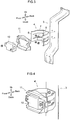
- FIG. 3 illustrates an example in which the radar device 10 is fixed to the protecting bracket 11 with bolts; the protecting bracket 11 is fixed to the EA bracket 4 by welding; and the EA bracket 4 is fixed to the cross linking member 3 with bolts. Any fixing manner can be applied and fixing with bolts or by welding are examples. In view of easiness in maintenance, it is preferable that the EA bracket 4 is removable from the cross linking member 3, and the radar device 10 is removable from the protecting bracket 11. Under a state where these parts are assembled to become a product, the radar device 10 is fixed to the cross linking member 3, keeping a distance from the cross linking member 3 in the front-to-rear direction of the vehicle, as illustrated in FIG. 4 .
- description will now be made in relation to a structure for mounting a radar with the EA bracket 4 and the protecting bracket 11.
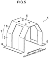
- the EA bracket 4 (fixing member) is provided with a fixing part 5, supporting parts 6, and deformable parts 7.
- the fixing part 5 is a portion to be fixed to the cross linking member 3.
- the fixing part 5 of the present embodiment is formed into a rectangular plate, and multiple holes through which fixing parts such as nuts and/or bolts are placed are formed on the fixing part 5.
- the EA bracket 4 is fixed to the cross linking member 3 by fixing the fixing part 5 to the cross linking member 3 under a state where the fixing part 5 is brought into face-to-face contact with the front face of the cross linking member 3.
- the EA bracket 4 is formed to have lower stiffness against external force in the front-to-rear direction of the vehicle than that of the cross linking member 3 (i.e., the EA bracket 4 is formed to more easily deform than the cross linking member 3 in the event of a collision on the front or rear end of the vehicle).
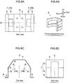
- the supporting parts 6 are portions that support the radar device 10. Each supporting part 6 is shaped into a rectangular plate parallel to the fixing part 5. The position of each supporting part 6 is distant from the fixing part 5 along the front-to-rear direction of the vehicle. As illustrated in FIGs. 5 and 6A-6D , the supporting parts 6 of the present embodiment are provided at two positions not overlapping the fixing part 5 when the fixing part 5 is seen from the direction perpendicular to the plate face of the fixing part 5. The longer sides of each supporting part 6 are set to the same as the longer side of the fixing part 5. In contrast, the shorter sides of each supporting part 6 are disposed so as to lie on lines straightly extended from the shorter side of the respective fixing part 5 when the fixing part 5 is seen from the direction perpendicular to the plate face of the fixing part 5.
- Each deformable part 7 is a portion having a shape that connects the fixing part 5 to the supporting part 6.
- the deformable parts 7 have functions for bending and deforming when external force caused by a collision on the front or rear end of the vehicle is input into the radar device 10 and for absorbing shock.
- the deformable parts 7 are provided at two positions.
- One of the deformable parts 7 is in the form of a face that connects one side of the fixing part 5 to the edge side of the supporting part 6.
- the other deformable part 7 is in the form of a face that connects the other side of the fixing part 5 and the edge side of the supporting part 6.
- Each deformable part 7 of the present embodiment is provided with an inclined face 8 and a vertical face 9.
- the inclined face 8 is a portion in the form of a flat face inclined from the fixing part 5 outwards in the vehicle-width direction (see FIG. 5 ).
- the angle A formed by the inclined face 8 and the fixing part 5 is set to less than the 180° and more than 90°, and is preferably around 120°.
- the vertical face 9 is a portion formed into a flat face inclined with respect to the inclined face 8 and perpendicular to the supporting part 6.
- the angle B formed by the vertical face 9 and the inclined face 8 is (270-A)° and the angle C formed by the vertical face 9 and the supporting part 6 is 90°. Accordingly, each deformable part 7 bend in an oblique "L" shape at the boundary between the inclined face 8 and the vertical face 9.
- the EA bracket 4 of the present embodiment includes oblique "L"-shaped deformable parts 7 at two positions, the entire EA bracket 4 can be regarded as having a U shape.
- the shape of the top face of the EA bracket 4 is formed by cutting an octagon formed by four pairs of parallel opposite sides with a line perpendicular to an arbitrary pair of opposite sides and then attaching the supporting parts 6.
- the EA bracket 4 is arranged so as to spread towards the front when seen from the top, and is attached to the cross linking member 3 in such a posture that the fixing part 5 is positioned rearwards the supporting part 6.
- first deformable portion 7A one of the two deformable parts 7 connected to one of the supporting parts 6
- second deformable portion 7B the other one of the deformable parts 7 connected to the other supporting part 6
- the first deformable portion 7A is formed into a shape being planar symmetric to the second deformable portion 7B.
- the one-dotted lines in the top view FIG. 6C and the rear view FIG. 6A represent positions of the imaginary symmetric plane D to the first deformable portion 7A and the second deformable portion 7B.
- Each of the first deformable portion 7A and the second deformable portion 7B is formed into a bifurcated shape (when seen from side) being planar symmetrical with respect to a horizontal imaginary orthogonal plane E to an imaginary symmetric plane D.
- the two-dotted lines in the top view FIG. 6C and the side view FIG. 6D represent the position of the imaginary orthogonal plane E.
- the bifurcated shape means that the deformable parts 7 are bifurcated on the ends of the supporting parts 6.
- the EA bracket 4 of the present invention includes the first deformable portion 7A and the second deformable portion 7B that are opposite to each other in the vehicle-width direction when seen from the top.
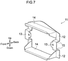
- the protecting bracket 11 (protecting member) is provided with first mounting parts 12, second mounting parts 13, guard parts 14, and connecting parts 15.
- the first mounting parts 12 are portions to be mounted on the supporting parts 6 of the EA bracket 4, and the second mounting parts 13 are portions mounted thereon the radar device 10.
- the first mounting parts 12 of the present invention are each formed into a flat face and fixed to the supporting part 6 by welding, being in the state of face-to-face contact with the supporting part 6.
- the protecting bracket 11 includes four first mounting parts 12, and two first mounting parts 12 are provided to each supporting part 6 so as to be vertically distant from each other.
- Each second mounting part 13 is formed into a flat plate parallel with the first mounting parts 12.
- the second mounting parts 13 are positioned distantly from the first mounting parts 12 in the front-to-rear direction of the vehicle. As illustrated in the front view FIG. 8B , each second mounting part 13 is provided at a position sandwiched by a pair of the first mounting parts 12 fixed to the same supporting part 6 by welding.
- the protecting bracket 11 is provided with two second mounting part 13, which are provided distantly from each other in the vehicle-width direction. On each of the second mounting part 13, a hole through which a fixing part, such as a nut and/or a bolt, are placed is formed.
- the protecting bracket 11 is fixed to the radar device 10 by fixing the second mounting part 13 being in a state of overlaying the installing bracket of the radar device 10.
- the guard parts 14 are portions that protrude outwards in the front-to-rear direction of the vehicle further than the radar device 10 when the protecting bracket 11 is fixed to the radar device 10. As illustrated in the front view FIG. 8B , the guard parts 14 are disposed so as to horizontally extend along the top-edge face and the bottom-edge face of the radar device 10. The guard parts 14 of the present embodiment protrude towards the front of the vehicle and have the protruding edges formed to curve along the inner surface of the bumper facer 22. The guard parts 14 are disposed so as to connect the first mounting parts 12 on the left end and the right end. Of the two guard parts 14, the upper guard part 14 has a tip that curves upwards and the lower guard part 14 has a tip that curves downwards.
- the connecting parts 15 are portions that connect the first mounting part 12 to the second mounting part 13 in the front-to-rear direction of the vehicle.
- the protecting bracket 11 is provided with four connecting parts 15, and two connecting parts 15 are provided to each second mounting part 13. As illustrated in the side view FIG. 8C , the position of the first mounting part 12 is staggered from that the second mounting part 13 in the front-to-rear direction of the vehicle. Connecting the second mounting part 13 with the first mounting parts 12 by the connecting parts 15 forms a crank-shaped supporting structure.
- the connecting parts 15 are provided at the upper end and the lower end of each second mounting part 13. Consequently, the stress transmission path from the second mounting part 13 to the first mounting parts 12 through the connecting parts 15 has a shape of a protrusion when seen from the side of the vehicle.
- the protecting bracket 11 of the present embodiment is formed so as to have a higher stiffness against external force in the front-to-rear direction of the vehicle than that of the EA bracket 4. With this configuration, the EA bracket 4 more easily deforms than the protecting bracket 11 in the event of a collision on the front or rear end of the vehicle.
- the supporting structure formed of the first mounting parts 12, the second mounting part 13, and the connecting parts 15 less easily deforms than the EA bracket 4, but has a similar capability of shock absorbance. Accordingly, both the EA bracket 4 and the protecting bracket 11 have the capability of shock absorbance, so that the protectability for the cross linking member 3 against the impact load can be enhanced.
- the protecting bracket 11 is formed to be planar symmetric with respect to an imaginary symmetric plane F.
- the one-dotted line in the top view FIG. 8A and the front view FIG. 8B represents the position of the imaginary symmetric plane F.
- the imaginary symmetric plane F corresponds to the imaginary symmetric plane D of the EA bracket 4, and the imaginary symmetric plane D and the imaginary symmetric plane F coincides with each other when the EA bracket 4 and the protecting bracket 11 are fixed.
- the EA bracket 4 may have an opposite structure in the front-to-rear direction of the vehicle as illustrated in FIGs. 10A and 10B .
- the deformable parts 7 can be bent and deformed at the boundary portion between the vertical face 9 and the inclined face 8, and therefore can absorb the impact load.
- the load acting on the connection between the inclined face 8 and the vertical face 9 easily distributed, so that the impact load (maximum load) is slightly increased.
- the arrangement structure illustrated in FIGs. 10A and 10B can reduce the injury value in the event of collision with a pedestrian by reducing the initial load.
- the EA bracket 4 may be arranged such that the first deformable portion 7A and the second deformable portion 7B vertically opposite to each other.
- the deformable parts 7 come to be easily displaced and the stiffness against the vibration of the vehicle in the vertical direction lowers slightly.
- the stiffness against the vibration of the vehicle in the vehicle-width direction is increased. Accordingly, the state of fixing the EA bracket 4 can be stabilized in the vehicle-width direction, so that the detecting precision of the radar device 10 can be enhanced.
Landscapes
- Engineering & Computer Science (AREA)
- Mechanical Engineering (AREA)
- Radar, Positioning & Navigation (AREA)
- Remote Sensing (AREA)
- Chemical & Material Sciences (AREA)
- Transportation (AREA)
- Combustion & Propulsion (AREA)
- Physics & Mathematics (AREA)
- Human Computer Interaction (AREA)
- Electromagnetism (AREA)
- Computer Networks & Wireless Communication (AREA)
- General Physics & Mathematics (AREA)
- Radar Systems Or Details Thereof (AREA)
- Body Structure For Vehicles (AREA)
Abstract
Description
- The present invention relates to a structure for mounting a radar on a vehicle.
- There has been developed a technique that arranges a radar device on a front or rear portion of a vehicle to rapidly detect the presence of an article or a pedestrian around the vehicle and thereby draw the driver's attention or activate the automatic brake. A radar device to detect an article in the front direction of the vehicle is usually arranged inside the bumper facer. For example, the detectability of the radar device is ensured by forming the radar device of a material having permeability to electromagnetic waves and shaping the surface portion of the bumper corresponding to the range of passing the electromagnetic wave emitted from the radar device into a smooth flat surface. It has been also known that the radar device is disposed inside the front grill disposed on the front end of the vehicle.
- It is preferable that the radar device is disposed as close to the bumper facer as possible to enhance the detectability for an object by the radar device. Namely, the partial area of the bumper facer within the range of passing irradiated with the electromagnetic wave is designed to be as small as possible to reduce the restriction on shape and shape of the bumper facer. Meanwhile, since clearances are set on the front and rear end of the vehicle to endure a collision at the front and rear ends of the vehicle, the vehicle may sometimes have no vehicle body structure to mount the radar device in the vicinity of the bumper facer. As a solution to the above, a structure has been proposed which suspends a bracket between two width-across member disposed inside the bumper facer and mounts the radar device on the bracket (e.g.,
JP-A 2009-287950 - However, an external force caused from a collision at the front or rear end may be input into the radar device. If the bracket of the radar device is deformed by the external force, there is a possibility that the deformation damages an on-board device (e.g., the radiator or the oil cooler) disposed in the vicinity of the bracket. In contrast, if the deformation is suppressed by increasing the stiffness of the bracket, the collision load would not be adequately absorbed. As the above, a traditional radar device have had a difficulty in adopting a mounting structure capable of achieving both shock absorbability and detectability.
- With the foregoing problem in view, one of the object of the present embodiment is to provide a structure for mounting a radar device capable of achieving both shock absorbability and detectability. In addition to the above objects, advantages derived from the structures to be detailed in the following "DESCRIPTION OF EMBODIMENTS" but traditional techniques have not achieved can be regarded as other objects of the present embodiment.
- The structure for mounting a radar disclosed herein includes a cross linking member that vertically connects two width-across members aligned in a front-to-rear direction of a vehicle. The structure further includes: a fixing member including a fixing part fixed to the cross linking member; a supporting part that supports a radar device, and a deformable part that has a shape connecting the fixing part and the supporting part and that bends and deforms to absorb shock when an external force is input into the radar device.
- The configuration in which the radar device is fixed to the cross linking member by the fixing member supporting the radar device makes the radar device possible to come close to the bumper, so that the detectability of the radar can be enhanced. Providing the deformable part to the fixing member can enhance the capability of absorbing shock and can consequently enhance the protectablity of the cross linking member against the impact load.
- The nature of this invention, as well as other objects and advantages thereof, will be explained in the following with reference to the accompanying drawings, in which like reference characters designate the same or similar parts throughout the figures and wherein:
-
FIG. 1 is a perspective view of a vehicle adopting a structure for mounting a radar according to an embodiment; -
FIG. 2 is a sectional view of a structure for mounting a radar; -
FIG. 3 is an exploded perspective view of a structure for mounting a radar; -
FIG. 4 is a perspective view of a structure for mounting a radar; -
FIG. 5 is a perspective view of an EA bracket; -
FIG. 6A is a rear view of an EA bracket;FIG. 6B is an oblique perspective view of an EA bracket;FIG. 6C is a top view of an EA bracket; andFIG. 6D is a side view of an EA bracket; -
FIG. 7 is a perspective view of a protecting bracket; -
FIG. 8A is a top view of a protecting bracket;FIG. 8B is a front view of a protecting bracket; andFIG. 8C is a side view of a protecting bracket; -
FIGs. 9A and 9B are diagrams illustrating deformed shapes; and -
FIGs. 10A-10D are diagrams illustrating modification to a structure for mounting a radar. - As illustrated in perspective in
FIG. 1 , a structure for mounting a radar according to an embodiment is applied inside thebumper facer 22 disposed on the front end of the vehicle. On the front end of the vehicle, abumper beam 1 and theupper bar 2 are extend in the vehicle-width direction. As illustrated inFIG. 2 , thebumper beam 1 is a structural member (width-across member) disposed inside thebumper facer 22 and is fixed to a side member or the cross member. If a cross member is disposed in the vicinity of the front end of the vehicle, thebumper beam 1 may be read as the cross member. - As illustrated in
FIG. 2 , aradar device 10 is disposed inside of thebumper facer 22. Thebumper facer 22 is a resin molded product having permeability to electromagnetic waves (e.g., microwave or millimeter wave) emitted from theradar device 10. - An
upper bar 2 is arranged above thebumper beam 1. Theupper bar 2 is a width-across member that supports the top sides of aheat exchanger 18,such as an oil cooler or a radiator, and also supports the front end of the engine hood. The top side of a headlamp disposed on the front end of the vehicle is also supported by theupper bar 2. Theupper bar 2 of the present embodiment is arranged slightly rearwards (backwards) to the upright of thebumper beam 1. - A
cross linking member 3 is disposed between thebumper beam 1 and theupper bar 2 so as to vertically connect thebumper beam 1 and theupper bar 2. Thecross linking member 3 is arranged approximately at the center of the vehicle width direction. As illustrated inFIG. 2 , thecross linking member 3 has a vertical section in the form of stairs that declines towards the front end of the vehicle and having a step inclines downwards. This can avoid interface with theheat exchanger 18, which is arranged under theupper bar 2. The top-edge portion of thecross linking member 3 is fixed to the front face of theupper bar 2 and the bottom-edge portion thereof is fixed to the rear (back) face of thebumper beam 1. - As illustrated in
FIGs. 3 and 4 , theradar device 10 is mounted to the front face of thecross linking member 3 via an EAbracket 4 and a protectingbracket 11. The EAbracket 4 is a bracket having a function for abating the impact by bending and deforming in the event of a collision at the front end of the vehicle. The word "EA" included in the EAbracket 4 is an abbreviation for "Energy Absorption". In contrast to the above, the protectingbracket 11 is a bracket having a function for protecting theradar device 10 from the impact caused by a collision at the front end of the vehicle. Combination use of theEA bracket 4 and the protectingbracket 11 enhances the protectability for theradar device 10 and abates the impact load to be transmitted to thecross linking member 3. -
FIG. 3 illustrates an example in which theradar device 10 is fixed to the protectingbracket 11 with bolts; the protectingbracket 11 is fixed to theEA bracket 4 by welding; and theEA bracket 4 is fixed to thecross linking member 3 with bolts. Any fixing manner can be applied and fixing with bolts or by welding are examples. In view of easiness in maintenance, it is preferable that theEA bracket 4 is removable from thecross linking member 3, and theradar device 10 is removable from the protectingbracket 11. Under a state where these parts are assembled to become a product, theradar device 10 is fixed to thecross linking member 3, keeping a distance from thecross linking member 3 in the front-to-rear direction of the vehicle, as illustrated inFIG. 4 . Hereinafter, description will now be made in relation to a structure for mounting a radar with theEA bracket 4 and the protectingbracket 11. - As illustrated in
FIG. 5 , the EA bracket 4 (fixing member) is provided with a fixingpart 5, supportingparts 6, anddeformable parts 7. The fixingpart 5 is a portion to be fixed to thecross linking member 3. The fixingpart 5 of the present embodiment is formed into a rectangular plate, and multiple holes through which fixing parts such as nuts and/or bolts are placed are formed on the fixingpart 5. TheEA bracket 4 is fixed to thecross linking member 3 by fixing the fixingpart 5 to thecross linking member 3 under a state where the fixingpart 5 is brought into face-to-face contact with the front face of thecross linking member 3. TheEA bracket 4 is formed to have lower stiffness against external force in the front-to-rear direction of the vehicle than that of the cross linking member 3 (i.e., theEA bracket 4 is formed to more easily deform than thecross linking member 3 in the event of a collision on the front or rear end of the vehicle). - The supporting
parts 6 are portions that support theradar device 10. Each supportingpart 6 is shaped into a rectangular plate parallel to the fixingpart 5. The position of each supportingpart 6 is distant from the fixingpart 5 along the front-to-rear direction of the vehicle. As illustrated inFIGs. 5 and6A-6D , the supportingparts 6 of the present embodiment are provided at two positions not overlapping the fixingpart 5 when the fixingpart 5 is seen from the direction perpendicular to the plate face of the fixingpart 5. The longer sides of each supportingpart 6 are set to the same as the longer side of the fixingpart 5. In contrast, the shorter sides of each supportingpart 6 are disposed so as to lie on lines straightly extended from the shorter side of the respective fixingpart 5 when the fixingpart 5 is seen from the direction perpendicular to the plate face of the fixingpart 5. - Each
deformable part 7 is a portion having a shape that connects the fixingpart 5 to the supportingpart 6. Thedeformable parts 7 have functions for bending and deforming when external force caused by a collision on the front or rear end of the vehicle is input into theradar device 10 and for absorbing shock. Like the supportingparts 6, thedeformable parts 7 are provided at two positions. One of thedeformable parts 7 is in the form of a face that connects one side of the fixingpart 5 to the edge side of the supportingpart 6. The otherdeformable part 7 is in the form of a face that connects the other side of the fixingpart 5 and the edge side of the supportingpart 6. Eachdeformable part 7 of the present embodiment is provided with aninclined face 8 and avertical face 9. - The
inclined face 8 is a portion in the form of a flat face inclined from the fixingpart 5 outwards in the vehicle-width direction (seeFIG. 5 ). As illustrated in the top viewFIG. 6C , the angle A formed by theinclined face 8 and the fixingpart 5 is set to less than the 180° and more than 90°, and is preferably around 120°. Thevertical face 9 is a portion formed into a flat face inclined with respect to theinclined face 8 and perpendicular to the supportingpart 6. The angle B formed by thevertical face 9 and theinclined face 8 is (270-A)° and the angle C formed by thevertical face 9 and the supportingpart 6 is 90°. Accordingly, eachdeformable part 7 bend in an oblique "L" shape at the boundary between theinclined face 8 and thevertical face 9. - Since, as illustrated in the top view of
FIG. 6C , theEA bracket 4 of the present embodiment includes oblique "L"-shapeddeformable parts 7 at two positions, theentire EA bracket 4 can be regarded as having a U shape. In a different viewpoint, the shape of the top face of theEA bracket 4 is formed by cutting an octagon formed by four pairs of parallel opposite sides with a line perpendicular to an arbitrary pair of opposite sides and then attaching the supportingparts 6. As illustrated in an oblique perspective viewFIG. 6B , theEA bracket 4 is arranged so as to spread towards the front when seen from the top, and is attached to thecross linking member 3 in such a posture that the fixingpart 5 is positioned rearwards the supportingpart 6. - Here, one of the two
deformable parts 7 connected to one of the supportingparts 6 is referred to as a firstdeformable portion 7A and the other one of thedeformable parts 7 connected to the other supportingpart 6 is referred to as a seconddeformable portion 7B. The firstdeformable portion 7A is formed into a shape being planar symmetric to the seconddeformable portion 7B. The one-dotted lines in the top viewFIG. 6C and the rear viewFIG. 6A represent positions of the imaginary symmetric plane D to the firstdeformable portion 7A and the seconddeformable portion 7B. Each of the firstdeformable portion 7A and the seconddeformable portion 7B is formed into a bifurcated shape (when seen from side) being planar symmetrical with respect to a horizontal imaginary orthogonal plane E to an imaginary symmetric plane D. The two-dotted lines in the top viewFIG. 6C and the side viewFIG. 6D represent the position of the imaginary orthogonal plane E. The bifurcated shape means that thedeformable parts 7 are bifurcated on the ends of the supportingparts 6. TheEA bracket 4 of the present invention includes the firstdeformable portion 7A and the seconddeformable portion 7B that are opposite to each other in the vehicle-width direction when seen from the top. - As illustrated in
FIG. 7 , the protecting bracket 11 (protecting member) is provided with first mountingparts 12, second mountingparts 13,guard parts 14, and connectingparts 15. The first mountingparts 12 are portions to be mounted on the supportingparts 6 of theEA bracket 4, and the second mountingparts 13 are portions mounted thereon theradar device 10. The first mountingparts 12 of the present invention are each formed into a flat face and fixed to the supportingpart 6 by welding, being in the state of face-to-face contact with the supportingpart 6. The protectingbracket 11 includes four first mountingparts 12, and two first mountingparts 12 are provided to each supportingpart 6 so as to be vertically distant from each other. - Each second mounting
part 13 is formed into a flat plate parallel with the first mountingparts 12. The second mountingparts 13 are positioned distantly from the first mountingparts 12 in the front-to-rear direction of the vehicle. As illustrated in the front viewFIG. 8B , each second mountingpart 13 is provided at a position sandwiched by a pair of the first mountingparts 12 fixed to the same supportingpart 6 by welding. The protectingbracket 11 is provided with two second mountingpart 13, which are provided distantly from each other in the vehicle-width direction. On each of the second mountingpart 13, a hole through which a fixing part, such as a nut and/or a bolt, are placed is formed. The protectingbracket 11 is fixed to theradar device 10 by fixing the second mountingpart 13 being in a state of overlaying the installing bracket of theradar device 10. - The
guard parts 14 are portions that protrude outwards in the front-to-rear direction of the vehicle further than theradar device 10 when the protectingbracket 11 is fixed to theradar device 10. As illustrated in the front viewFIG. 8B , theguard parts 14 are disposed so as to horizontally extend along the top-edge face and the bottom-edge face of theradar device 10. Theguard parts 14 of the present embodiment protrude towards the front of the vehicle and have the protruding edges formed to curve along the inner surface of thebumper facer 22. Theguard parts 14 are disposed so as to connect the first mountingparts 12 on the left end and the right end. Of the twoguard parts 14, theupper guard part 14 has a tip that curves upwards and thelower guard part 14 has a tip that curves downwards. - The connecting
parts 15 are portions that connect the first mountingpart 12 to the second mountingpart 13 in the front-to-rear direction of the vehicle. The protectingbracket 11 is provided with four connectingparts 15, and two connectingparts 15 are provided to each second mountingpart 13. As illustrated in the side viewFIG. 8C , the position of the first mountingpart 12 is staggered from that the second mountingpart 13 in the front-to-rear direction of the vehicle. Connecting the second mountingpart 13 with the first mountingparts 12 by the connectingparts 15 forms a crank-shaped supporting structure. In the present embodiment, the connectingparts 15 are provided at the upper end and the lower end of each second mountingpart 13. Consequently, the stress transmission path from the second mountingpart 13 to the first mountingparts 12 through the connectingparts 15 has a shape of a protrusion when seen from the side of the vehicle. - The protecting
bracket 11 of the present embodiment is formed so as to have a higher stiffness against external force in the front-to-rear direction of the vehicle than that of theEA bracket 4. With this configuration, theEA bracket 4 more easily deforms than the protectingbracket 11 in the event of a collision on the front or rear end of the vehicle. The supporting structure formed of the first mountingparts 12, the second mountingpart 13, and the connectingparts 15 less easily deforms than theEA bracket 4, but has a similar capability of shock absorbance. Accordingly, both theEA bracket 4 and the protectingbracket 11 have the capability of shock absorbance, so that the protectability for thecross linking member 3 against the impact load can be enhanced. - The protecting
bracket 11 is formed to be planar symmetric with respect to an imaginary symmetric plane F. The one-dotted line in the top viewFIG. 8A and the front viewFIG. 8B represents the position of the imaginary symmetric plane F. The imaginary symmetric plane F corresponds to the imaginary symmetric plane D of theEA bracket 4, and the imaginary symmetric plane D and the imaginary symmetric plane F coincides with each other when theEA bracket 4 and the protectingbracket 11 are fixed. - When an impact load from the front end of the vehicle acts on the
radar device 10, external force is input from theradar device 10 into theEA bracket 4 through the protectingbracket 11. The external force is represented by the black arrows inFIG. 9A , and the internal force (internal stress) in theEA bracket 4 is represented by the white arrows. Thevertical face 9 of theEA bracket 4 extends in the same front-to-rear direction as the direction of the external force (i.e., the direction in which the impact load is inputted). For the above, the load becomes large at the initial phase during which theEA bracket 4 deforms to enhance the deceleration effects of an impact target. Since the vector of the internal force coincides with the direction in which the impact target enters, the load that acts on the connection between thevertical face 9 and theinclined face 8 is not distributed very much. Consequently, as illustrated by the broken line ofFIG. 9A , the boundary portion between thevertical face 9 and theinclined face 8 easily bends and deforms, so that the impact load is absorbed. - (1) In the above structure for mounting a radar, the
radar device 10 is fixed to thecross linking member 3 via theEA bracket 4. This configuration makes theradar device 10 possible to come closer to thebumper facer 22, so that the detectability of theradar device 10 can be enhanced. Providing thedeformable parts 7 to theEA bracket 4 can enhance the capability of shock absorbance, so that the protectability for thecross linking member 3 against the impact load can be enhanced. Accordingly, both capability of shock absorbance and detectability can be enhanced. Further, after the collision, it is satisfactorily to replace only theEA bracket 4, so that the maintenance facility of the vehicle can be enhanced. - (2) In the above structure for mounting a radar, the
vertical face 9 is provided to eachdeformable part 7. With this structure, it is possible to ensure the distance from thecross linking member 3 to theradar device 10, making theradar device 10 possible to be further come closer to thebumper facer 22. Since it is possible to align the direction of the impact load with the direction of transmitting the stress, the load (initial load) at the initial stage of a collision can be increased, so that the deceleration effect can be enhanced. In contrast, providing theinclined face 8 behind thevertical face 9 can displace the direction in which the external force acts from the direction of transmitting the stress, so that the bend and deformation of thedeformable parts 7 can be promoted. Thereby, the impact load (maximum load) can be reduced, expecting to reduce the injury value in the event of collision with a pedestrian. In addition to the above, it is possible to inhibit the load acting on the connection between thevertical face 9 andinclined face 8 from being distributed, so that the bend and deformation of thedeformable parts 7 can be promoted. - (3) The
deformable part 7 is formed by arranging the firstdeformable portion 7A and the seconddeformable portion 7B to be planar symmetric to each other. This configuration can suppress the vibration of theEA bracket 4 in the direction along the imaginary symmetric plane D of the firstdeformable portion 7A and the seconddeformable portion 7B. Consequently, the state of fixing theEA bracket 4 can be stabilized through the use of theEA bracket 4, so that the detecting precision of theradar device 10 can be enhanced. - (4) Eac of the first
deformable portion 7A and the seconddeformable portion 7B is formed into a bifurcated shape that is planar symmetrical with respect to the imaginary orthogonal plane E to the imaginary symmetric plane D. This configuration can suppress the vibration of theEA bracket 4 in the direction along the imaginary orthogonal plane E. Consequently, the state of fixing theEA bracket 4 can be stabilized through the use of theEA bracket 4, so that the detecting precision of theradar device 10 can be enhanced. Placing the two routs of transmission of stress vertically distant from each other can ensure the stiffness to endure the vertical vibration of the vehicle, so that the detecting precision of theradar device 10 can be further enhanced. In addition, thedeformable parts 7 can be formed to be light in weight. - (5) In the above embodiment, the first
deformable portion 7A and the seconddeformable portion 7B are arranged to opposite to each other in the vehicle-width direction. This arrangement can ensure the stiffness to endure the vertical vibration of the vehicle, so that the detecting precision of theradar device 10 can be enhanced. As illustrated inFIG. 3 , theEA bracket 4 is arranged so as to spread towards the front when seen from the top. This arrangement can ensure the stiffness to endure the vertical vibration of the vehicle as compared with a structure that theEA bracket 4 is arrange sideways, so that the detecting precision of theradar device 10 can be further enhanced. - (6) The
EA bracket 4 is formed so as to have a lower stiffness against external force in the front-to-rear direction of the vehicle than that of thecross linking member 3. In other words, the geometrical moment of inertia of theEA bracket 4 with respect to the axis in the front-to-rear direction of the vehicle is designed so as to be smaller than that of thecross linking member 3. This design can allow theEA bracket 4 to more easily bend and deform than thecross linking member 3. Accordingly, it is possible to abate an input of the impact load into thecross linking member 3, so that the protectability for thecross linking member 3 can be enhanced. - (7) As illustrated in
FIG. 7 , theguard parts 14 are provided to the protectingbracket 11 to protect theradar device 10. The presence of theguard parts 14 can prevent load from directly inputting into theradar device 10, so that the protectability for theradar device 10 can be enhanced. - (8) Arranging the
guard parts 14 horizontally along the top-edge face and the bottom-edge face of theradar device 10 appropriately protects the top-edge and bottom-edges of theradar device 10 where the impact load is likely input. Accordingly, the protectability for theradar device 10 can be further improved. - (9) As illustrated in the side view
fig 8C , the connectingparts 15 extending along the front-to-rear direction of the vehicle are provided between the first mountingparts 12 and the second mountingparts 13. This can form a crank-shaped supporting structure. The positions of the first mountingparts 12 can be easily displaced from those of the second mountingparts 13 in the front-to-rear direction, so that the freedom in layout can be enhanced. - (10) The protecting
bracket 11 is formed so as to have a higher stiffness against external force in the front-to-rear direction of the vehicle than that of theEA bracket 4. In other words, the geometrical moment of inertia of the protectingbracket 11 with respect to the axis in the front-to-rear direction of the vehicle is designed so as to be larger than that of theEA bracket 4. This design can allow theEA bracket 4 to more easily bend and deform than the protectingbracket 11. - The foregoing embodiment is exemplary and has no intention to exclude various modifications and applications of techniques not referred in the present embodiment. In other words, various changes and modifications can be suggested without departing from the scope of the present embodiment. The present embodiment and the modifications can be selected, omitted, or combined according to the requirement.
- Alternatively, the
EA bracket 4 may have an opposite structure in the front-to-rear direction of the vehicle as illustrated inFIGs. 10A and 10B . Also in this case, as shown by the broken line ofFIG. 9B , thedeformable parts 7 can be bent and deformed at the boundary portion between thevertical face 9 and theinclined face 8, and therefore can absorb the impact load. As compared with the structure ofFIG. 9A , since the vector of the internal force is different from the direction in which an impact target is input , the load acting on the connection between theinclined face 8 and thevertical face 9 easily distributed, so that the impact load (maximum load) is slightly increased. However, since the direction in which the internal force (internal stress) acts in theEA bracket 4 is different from the direction in which the external force acts in theEA bracket 4, the load at the initial stage, when theEA bracket 4 deforms, is decreased. Accordingly, the arrangement structure illustrated inFIGs. 10A and 10B can reduce the injury value in the event of collision with a pedestrian by reducing the initial load. - As illustrated in
FIGs. 10C and 10D , theEA bracket 4 may be arranged such that the firstdeformable portion 7A and the seconddeformable portion 7B vertically opposite to each other. In this alternatively, thedeformable parts 7 come to be easily displaced and the stiffness against the vibration of the vehicle in the vertical direction lowers slightly. However, the stiffness against the vibration of the vehicle in the vehicle-width direction is increased. Accordingly, the state of fixing theEA bracket 4 can be stabilized in the vehicle-width direction, so that the detecting precision of theradar device 10 can be enhanced. -
- 1
- bumper beam (width-across member)
- 2
- upper bar (width-across member)
- 3
- cross linking member
- 4
- EA bracket (fixing member)
- 5
- fixing part
- 6
- supporting part
- 7
- deformable part
- 7A
- first deformable portion
- 7B
- second deformable portion
- 8
- inclined face
- 9
- vertical face
- 10
- radar device
- 11
- protecting bracket (protecting member)
- 12
- first mounting part
- 13
- second mounting part
- 14
- guard part
- 15
- connecting part
- 18
- heat exchanger
- 22
- bumper facer
- D
- imaginary symmetric plane
- E
- imaginary orthogonal plane
- F
- imaginary symmetric plane
Claims (10)
- A structure for mounting a radar comprising:a cross linking member (3) that vertically connects two width-across members (1,2) aligned in a front-to-rear direction of a vehicle; anda fixing member (4) comprising a fixing part (5) fixed to the cross linking member (3), a supporting part (6) that supports a radar device (10), a deformable part (7) that has a shape connecting the fixing part (5) and the supporting part (6) and that bends and deforms to absorb shock when an external force is input into the radar device (10).
- The structure for mounting a radar according to claim 1, wherein the deformable part (7) comprises:an inclined face (8) in a shape of a flat face inclined to the fixing part (5); anda vertical face (9) in a shape of a flat face that is inclined to the inclined face (8) and perpendicular to the supporting part (6).
- The structure for mounting a radar according to claim 1 or 2, wherein:two of the supporting parts (6) are provided;the deformable part (7) comprises:a first deformable portion (7A) that connects one edge of the fixing part (5) and one of the supporting parts (6); anda second deformable portion (7B) that connects a space between another edge of the fixing part (5) and another one of the supporting parts (6), and is formed into a shape planar symmetric to the second deformable portion (7B).
- The structure for mounting a radar according to claim 3, wherein each of the first deformable portion (7A) and the second deformable portion (7B) is formed into a bifurcated shape being planar symmetric with respect to an imaginary orthogonal plane (E) perpendicular to imaginary symmetric plane (D) of the first deformable portion (7A) and the second deformable portion (7B).
- The structure for mounting a radar according to claim 3 or 4, wherein the deformable part (7) is arranged such that the first deformable portion (7A) and the second deformable portion (7B) are opposite to each other in a width direction of the vehicle.
- The structure for mounting a radar according to one of claims 1-5, the deformable part (7) has a lower stiffness against external force in the front-to-rear direction of the vehicle than that of the cross linking member (3).
- The structure for mounting a radar according to one of claims 1-6, further comprising a protecting member (11) that comprises:a first mounting part (12) to be installed to the supporting member (6);a second mounting part (13) that mounts thereon the radar device (10); anda guard part (14) that protrudes outwards in the front-to-rear direction of the vehicle further than the radar device (10).
- The structure for mounting a radar according to claim 7, wherein two of the guard parts (14) are each disposed so as to horizontally extend along one of the top-edge face and the bottom-edge face of the radar device (10).
- The structure for mounting a radar according to claim 7 or 8, the protecting member (11) comprises a connecting part (15) that connects the first mounting part (12) and the second mounting part (13) in the front-to-rear direction of the vehicle.
- The structure for mounting a radar according to one of claims 7-9, the protecting member (11) has a higher stiffness against external force in the front-to-rear direction of the vehicle than that of the fixing member (4).
Applications Claiming Priority (1)
| Application Number | Priority Date | Filing Date | Title |
|---|---|---|---|
| JP2017029985A JP2018134936A (en) | 2017-02-21 | 2017-02-21 | Radar installation structure |
Publications (2)
| Publication Number | Publication Date |
|---|---|
| EP3363714A1 true EP3363714A1 (en) | 2018-08-22 |
| EP3363714B1 EP3363714B1 (en) | 2019-09-04 |
Family
ID=61189224
Family Applications (1)
| Application Number | Title | Priority Date | Filing Date |
|---|---|---|---|
| EP18155488.2A Active EP3363714B1 (en) | 2017-02-21 | 2018-02-07 | Structure for mounting radar |
Country Status (4)
| Country | Link |
|---|---|
| US (1) | US10793095B2 (en) |
| EP (1) | EP3363714B1 (en) |
| JP (1) | JP2018134936A (en) |
| CN (1) | CN108454549A (en) |
Cited By (2)
| Publication number | Priority date | Publication date | Assignee | Title |
|---|---|---|---|---|
| CN110893825A (en) * | 2018-08-24 | 2020-03-20 | 本田技研工业株式会社 | External sensor installation structure |
| DE102020103246A1 (en) | 2020-02-10 | 2021-08-12 | Bayerische Motoren Werke Aktiengesellschaft | Device for resetting a motor vehicle component after an impact and a motor vehicle equipped therewith |
Families Citing this family (38)
| Publication number | Priority date | Publication date | Assignee | Title |
|---|---|---|---|---|
| JP6590974B2 (en) * | 2018-03-23 | 2019-10-16 | 本田技研工業株式会社 | Body front structure |
| JP6786560B2 (en) * | 2018-09-26 | 2020-11-18 | 本田技研工業株式会社 | Body front structure |
| JP7155931B2 (en) | 2018-11-20 | 2022-10-19 | トヨタ自動車株式会社 | Vehicle sensor mounting structure |
| JP6932119B2 (en) * | 2018-12-04 | 2021-09-08 | 本田技研工業株式会社 | Detector and vehicle |
| JP6995734B2 (en) * | 2018-12-07 | 2022-01-17 | 本田技研工業株式会社 | Detection device |
| JP7063402B2 (en) * | 2019-02-06 | 2022-05-09 | 三菱自動車工業株式会社 | Radar mounting structure |
| CN110001562B (en) * | 2019-05-13 | 2023-10-13 | 重庆平伟汽车零部件有限公司 | Plug-in type mounting structure of automobile radar support |
| JP6842511B2 (en) * | 2019-07-31 | 2021-03-17 | 本田技研工業株式会社 | Sensor mounting structure on the side of the car body |
| KR102242930B1 (en) | 2019-08-22 | 2021-04-21 | 주식회사 만도 | Radar apparatus mounting assembly |
| CN210478550U (en) * | 2019-09-17 | 2020-05-08 | 延锋彼欧汽车外饰系统有限公司 | A Flexible Radar Mount That Absorbs Vibration Deviation |
| CN110803118B (en) * | 2019-11-21 | 2021-05-28 | 一汽解放汽车有限公司 | A vehicle radar installation structure, installation method and vehicle |
| JP7313266B2 (en) * | 2019-12-18 | 2023-07-24 | ロベルト・ボッシュ・ゲゼルシャフト・ミト・ベシュレンクテル・ハフツング | Adapters, radar units and vehicles |
| JP7100072B2 (en) * | 2020-01-08 | 2022-07-12 | 本田技研工業株式会社 | Sensor mounting bracket |
| JP7409926B2 (en) * | 2020-03-19 | 2024-01-09 | 本田技研工業株式会社 | Sensor mounting structure and moving object |
| JP7390243B2 (en) * | 2020-04-17 | 2023-12-01 | 株式会社ニフコ | Bracket for automotive equipment |
| CN212932950U (en) * | 2020-04-24 | 2021-04-09 | 北京智行者科技有限公司 | Ultrasonic radar fixed knot constructs |
| US11623585B2 (en) | 2020-04-30 | 2023-04-11 | Zoox, Inc. | Sensor pod coverage and placement on vehicle |
| US11953623B2 (en) | 2020-04-30 | 2024-04-09 | Zoox, Inc. | Sensor pod assembly |
| US11760313B2 (en) * | 2020-04-30 | 2023-09-19 | Zoox, Inc. | Sensor pod cleaning system |
| CN111796254B (en) * | 2020-06-04 | 2024-08-06 | 一汽奔腾轿车有限公司 | Laser radar installation fastening bracket device |
| US11433834B2 (en) * | 2020-09-30 | 2022-09-06 | Nissan North America, Inc. | Vehicle front end structure |
| JP2022063471A (en) * | 2020-10-12 | 2022-04-22 | トヨタ自動車株式会社 | Vehicular sensor mounting structure |
| FR3120334B1 (en) * | 2021-03-03 | 2023-01-20 | Psa Automobiles Sa | System for fixing a detection module for a motor vehicle |
| JP7182655B2 (en) * | 2021-03-09 | 2022-12-02 | 本田技研工業株式会社 | Vehicle sensor mounting structure |
| CN112896056B (en) * | 2021-03-15 | 2023-03-24 | 纵目科技(上海)股份有限公司 | Radar mounting structure and millimeter wave radar with same |
| JPWO2022196638A1 (en) * | 2021-03-19 | 2022-09-22 | ||
| JP7775539B2 (en) * | 2021-07-21 | 2025-11-26 | メルセデス・ベンツ グループ アクチェンゲゼルシャフト | Truck vehicle |
| CN113525250A (en) * | 2021-07-30 | 2021-10-22 | 奇瑞汽车股份有限公司 | Radar mounting device and automobile |
| CN113602204A (en) * | 2021-08-09 | 2021-11-05 | 斯卡纳(北京)科技有限公司 | Multi-line rotary laser radar device |
| JP2023098311A (en) * | 2021-12-28 | 2023-07-10 | 本田技研工業株式会社 | Structure to attach object detection device to vehicle body |
| JP2023098310A (en) * | 2021-12-28 | 2023-07-10 | 本田技研工業株式会社 | Mounting structure of the object detection device to the vehicle body |
| CN114407792B (en) * | 2022-02-21 | 2023-06-23 | 岚图汽车科技有限公司 | Corner radar headlight combination structure and bracket assembly |
| JP7470724B2 (en) * | 2022-02-21 | 2024-04-18 | 本田技研工業株式会社 | Mounting structure for object detection device on vehicle body |
| CN114802071A (en) * | 2022-03-29 | 2022-07-29 | 江铃汽车股份有限公司 | Radar supporting structure and car |
| EP4328618A1 (en) * | 2022-08-22 | 2024-02-28 | Tusimple, Inc. | Rear mounted radar for autonomous vehicles |
| JPWO2025032784A1 (en) * | 2023-08-09 | 2025-02-13 | ||
| JP7510656B1 (en) | 2024-04-02 | 2024-07-04 | 義英 土橋 | Scanning type vehicle-mounted imaging device |
| FR3164162A1 (en) | 2024-07-08 | 2026-01-09 | Stellantis Auto Sas | Motor vehicle bumper with radar blocking |
Citations (6)
| Publication number | Priority date | Publication date | Assignee | Title |
|---|---|---|---|---|
| US20050062641A1 (en) * | 2003-07-23 | 2005-03-24 | Fujitsu Ten Limited | Method for attaching radar for vehicle, radar for vehicle, and monitoring method |
| JP2009287950A (en) | 2008-05-27 | 2009-12-10 | Suzuki Motor Corp | Mounting structure of radar device |
| JP2015063196A (en) * | 2013-09-25 | 2015-04-09 | マツダ株式会社 | Object detection device mounting structure |
| DE102015119269A1 (en) * | 2014-11-17 | 2016-05-19 | Suzuki Motor Corporation | Vehicle body front structure |
| JP2016132276A (en) * | 2015-01-16 | 2016-07-25 | マツダ株式会社 | Vehicle front structure |
| JP2017215186A (en) * | 2016-05-31 | 2017-12-07 | 三菱自動車工業株式会社 | Vehicular radar device attachment structure |
Family Cites Families (15)
| Publication number | Priority date | Publication date | Assignee | Title |
|---|---|---|---|---|
| US5326133A (en) * | 1991-11-20 | 1994-07-05 | Automotive Technologies International Inc. | Sensor and bracket assembly |
| JP3741993B2 (en) * | 2001-03-29 | 2006-02-01 | 本田技研工業株式会社 | External sensing device |
| JP4331152B2 (en) * | 2005-09-20 | 2009-09-16 | 本田技研工業株式会社 | Object detection device mounting structure |
| DE102007019700A1 (en) | 2007-04-26 | 2008-10-30 | Dr. Ing. H.C. F. Porsche Aktiengesellschaft | Energy absorbing deformation element for a vehicle |
| JP5472223B2 (en) * | 2011-07-11 | 2014-04-16 | トヨタ自動車株式会社 | Fender panel mounting structure |
| US8833815B2 (en) | 2012-10-23 | 2014-09-16 | Ford Global Technologies, Llc | Bumper integrated forward radar mounting system |
| KR101459910B1 (en) | 2013-05-28 | 2014-11-07 | 현대자동차주식회사 | Radar apparatus for vehicle |
| FR3014404B1 (en) * | 2013-12-10 | 2017-03-24 | Peugeot Citroen Automobiles Sa | CARRIER FOR DISTANCE DETECTION RADAR ON MOTOR VEHICLE |
| US9673517B2 (en) * | 2014-04-30 | 2017-06-06 | Honda Motor Co., Ltd. | Vehicle radar cover assembly and method |
| US9682782B2 (en) * | 2014-12-04 | 2017-06-20 | Honeywell International Inc. | Plate-fin tubular hybrid heat exchanger design for an air and fuel cooled air cooler |
| CN204415318U (en) * | 2014-12-25 | 2015-06-24 | 惠州比亚迪电池有限公司 | A kind of door shield |
| FR3037017B1 (en) * | 2015-06-05 | 2020-06-12 | Renault S.A.S | VEHICLE RADAR SUPPORT |
| JP6311685B2 (en) * | 2015-09-29 | 2018-04-18 | トヨタ自動車株式会社 | Vehicle sensor mounting structure |
| CN205202930U (en) * | 2015-11-18 | 2016-05-04 | 凌云工业股份有限公司 | A aluminum alloy energy -absorbing box for GMT |
| US10493934B2 (en) * | 2017-11-28 | 2019-12-03 | Nissan North America, Inc. | Radar support structure |
-
2017
- 2017-02-21 JP JP2017029985A patent/JP2018134936A/en active Pending
-
2018
- 2018-01-05 CN CN201810011154.9A patent/CN108454549A/en active Pending
- 2018-02-07 EP EP18155488.2A patent/EP3363714B1/en active Active
- 2018-02-20 US US15/900,259 patent/US10793095B2/en not_active Expired - Fee Related
Patent Citations (6)
| Publication number | Priority date | Publication date | Assignee | Title |
|---|---|---|---|---|
| US20050062641A1 (en) * | 2003-07-23 | 2005-03-24 | Fujitsu Ten Limited | Method for attaching radar for vehicle, radar for vehicle, and monitoring method |
| JP2009287950A (en) | 2008-05-27 | 2009-12-10 | Suzuki Motor Corp | Mounting structure of radar device |
| JP2015063196A (en) * | 2013-09-25 | 2015-04-09 | マツダ株式会社 | Object detection device mounting structure |
| DE102015119269A1 (en) * | 2014-11-17 | 2016-05-19 | Suzuki Motor Corporation | Vehicle body front structure |
| JP2016132276A (en) * | 2015-01-16 | 2016-07-25 | マツダ株式会社 | Vehicle front structure |
| JP2017215186A (en) * | 2016-05-31 | 2017-12-07 | 三菱自動車工業株式会社 | Vehicular radar device attachment structure |
Cited By (2)
| Publication number | Priority date | Publication date | Assignee | Title |
|---|---|---|---|---|
| CN110893825A (en) * | 2018-08-24 | 2020-03-20 | 本田技研工业株式会社 | External sensor installation structure |
| DE102020103246A1 (en) | 2020-02-10 | 2021-08-12 | Bayerische Motoren Werke Aktiengesellschaft | Device for resetting a motor vehicle component after an impact and a motor vehicle equipped therewith |
Also Published As
| Publication number | Publication date |
|---|---|
| US20180236958A1 (en) | 2018-08-23 |
| EP3363714B1 (en) | 2019-09-04 |
| JP2018134936A (en) | 2018-08-30 |
| US10793095B2 (en) | 2020-10-06 |
| CN108454549A (en) | 2018-08-28 |
Similar Documents
| Publication | Publication Date | Title |
|---|---|---|
| EP3363714B1 (en) | Structure for mounting radar | |
| US7044246B2 (en) | Heat exchanger mounting structure for vehicle | |
| CN108071285B (en) | Hood Hinges | |
| US9650077B2 (en) | Car undercover | |
| JP5751238B2 (en) | Fender support structure | |
| US20180281863A1 (en) | Front chassis structure for automobile | |
| US9242676B2 (en) | Front vehicle body reinforcing structure | |
| US20130147217A1 (en) | Tubular Back Beam for Vehicle | |
| EP2666674B1 (en) | Vehicle body front structure on automobile | |
| JP6304505B2 (en) | Vehicle side body structure | |
| JP7063402B2 (en) | Radar mounting structure | |
| JP5969417B2 (en) | Body front structure | |
| US10717469B2 (en) | Vehicle body front part structure | |
| CN108394263B (en) | Power unit installation structure | |
| JP2005518294A (en) | Front panel of a car with a bumper beam | |
| KR20180077910A (en) | A bumper beam unit for vehicles | |
| JP3870677B2 (en) | Shock absorber for moving body | |
| JP2012224216A (en) | Vehicle body front structure | |
| US7866687B2 (en) | Vehicular airbag device | |
| JP2019137157A (en) | Attachment member | |
| KR102136535B1 (en) | Lower stiffener unit for vehicle | |
| CN219295537U (en) | Fender mounting bracket and vehicle | |
| CN224256599U (en) | Front structure of the vehicle body and vehicle | |
| KR20080008660A (en) | Automotive Front End Modules for Pedestrian Safety | |
| KR101049682B1 (en) | Car bumper module |
Legal Events
| Date | Code | Title | Description |
|---|---|---|---|
| PUAI | Public reference made under article 153(3) epc to a published international application that has entered the european phase |
Free format text: ORIGINAL CODE: 0009012 |
|
| STAA | Information on the status of an ep patent application or granted ep patent |
Free format text: STATUS: THE APPLICATION HAS BEEN PUBLISHED |
|
| AK | Designated contracting states |
Kind code of ref document: A1 Designated state(s): AL AT BE BG CH CY CZ DE DK EE ES FI FR GB GR HR HU IE IS IT LI LT LU LV MC MK MT NL NO PL PT RO RS SE SI SK SM TR |
|
| AX | Request for extension of the european patent |
Extension state: BA ME |
|
| STAA | Information on the status of an ep patent application or granted ep patent |
Free format text: STATUS: REQUEST FOR EXAMINATION WAS MADE |
|
| GRAP | Despatch of communication of intention to grant a patent |
Free format text: ORIGINAL CODE: EPIDOSNIGR1 |
|
| STAA | Information on the status of an ep patent application or granted ep patent |
Free format text: STATUS: GRANT OF PATENT IS INTENDED |
|
| 17P | Request for examination filed |
Effective date: 20190220 |
|
| RBV | Designated contracting states (corrected) |
Designated state(s): AL AT BE BG CH CY CZ DE DK EE ES FI FR GB GR HR HU IE IS IT LI LT LU LV MC MK MT NL NO PL PT RO RS SE SI SK SM TR |
|
| RIC1 | Information provided on ipc code assigned before grant |
Ipc: B60R 19/02 20060101ALI20190308BHEP Ipc: B62D 25/08 20060101AFI20190308BHEP |
|
| INTG | Intention to grant announced |
Effective date: 20190329 |
|
| RAP1 | Party data changed (applicant data changed or rights of an application transferred) |
Owner name: MITSUBISHI JIDOSHA KOGYO KABUSHIKI KAISHA |
|
| GRAS | Grant fee paid |
Free format text: ORIGINAL CODE: EPIDOSNIGR3 |
|
| GRAA | (expected) grant |
Free format text: ORIGINAL CODE: 0009210 |
|
| STAA | Information on the status of an ep patent application or granted ep patent |
Free format text: STATUS: THE PATENT HAS BEEN GRANTED |
|
| AK | Designated contracting states |
Kind code of ref document: B1 Designated state(s): AL AT BE BG CH CY CZ DE DK EE ES FI FR GB GR HR HU IE IS IT LI LT LU LV MC MK MT NL NO PL PT RO RS SE SI SK SM TR |
|
| REG | Reference to a national code |
Ref country code: GB Ref legal event code: FG4D |
|
| REG | Reference to a national code |
Ref country code: CH Ref legal event code: EP |
|
| REG | Reference to a national code |
Ref country code: AT Ref legal event code: REF Ref document number: 1174958 Country of ref document: AT Kind code of ref document: T Effective date: 20190915 |
|
| REG | Reference to a national code |
Ref country code: DE Ref legal event code: R096 Ref document number: 602018000538 Country of ref document: DE |
|
| REG | Reference to a national code |
Ref country code: IE Ref legal event code: FG4D |
|
| REG | Reference to a national code |
Ref country code: NL Ref legal event code: MP Effective date: 20190904 |
|
| REG | Reference to a national code |
Ref country code: LT Ref legal event code: MG4D |
|
| PG25 | Lapsed in a contracting state [announced via postgrant information from national office to epo] |
Ref country code: NO Free format text: LAPSE BECAUSE OF FAILURE TO SUBMIT A TRANSLATION OF THE DESCRIPTION OR TO PAY THE FEE WITHIN THE PRESCRIBED TIME-LIMIT Effective date: 20191204 Ref country code: BG Free format text: LAPSE BECAUSE OF FAILURE TO SUBMIT A TRANSLATION OF THE DESCRIPTION OR TO PAY THE FEE WITHIN THE PRESCRIBED TIME-LIMIT Effective date: 20191204 Ref country code: FI Free format text: LAPSE BECAUSE OF FAILURE TO SUBMIT A TRANSLATION OF THE DESCRIPTION OR TO PAY THE FEE WITHIN THE PRESCRIBED TIME-LIMIT Effective date: 20190904 Ref country code: LT Free format text: LAPSE BECAUSE OF FAILURE TO SUBMIT A TRANSLATION OF THE DESCRIPTION OR TO PAY THE FEE WITHIN THE PRESCRIBED TIME-LIMIT Effective date: 20190904 Ref country code: SE Free format text: LAPSE BECAUSE OF FAILURE TO SUBMIT A TRANSLATION OF THE DESCRIPTION OR TO PAY THE FEE WITHIN THE PRESCRIBED TIME-LIMIT Effective date: 20190904 Ref country code: HR Free format text: LAPSE BECAUSE OF FAILURE TO SUBMIT A TRANSLATION OF THE DESCRIPTION OR TO PAY THE FEE WITHIN THE PRESCRIBED TIME-LIMIT Effective date: 20190904 |
|
| PG25 | Lapsed in a contracting state [announced via postgrant information from national office to epo] |
Ref country code: AL Free format text: LAPSE BECAUSE OF FAILURE TO SUBMIT A TRANSLATION OF THE DESCRIPTION OR TO PAY THE FEE WITHIN THE PRESCRIBED TIME-LIMIT Effective date: 20190904 Ref country code: LV Free format text: LAPSE BECAUSE OF FAILURE TO SUBMIT A TRANSLATION OF THE DESCRIPTION OR TO PAY THE FEE WITHIN THE PRESCRIBED TIME-LIMIT Effective date: 20190904 Ref country code: ES Free format text: LAPSE BECAUSE OF FAILURE TO SUBMIT A TRANSLATION OF THE DESCRIPTION OR TO PAY THE FEE WITHIN THE PRESCRIBED TIME-LIMIT Effective date: 20190904 Ref country code: RS Free format text: LAPSE BECAUSE OF FAILURE TO SUBMIT A TRANSLATION OF THE DESCRIPTION OR TO PAY THE FEE WITHIN THE PRESCRIBED TIME-LIMIT Effective date: 20190904 Ref country code: GR Free format text: LAPSE BECAUSE OF FAILURE TO SUBMIT A TRANSLATION OF THE DESCRIPTION OR TO PAY THE FEE WITHIN THE PRESCRIBED TIME-LIMIT Effective date: 20191205 |
|
| REG | Reference to a national code |
Ref country code: AT Ref legal event code: MK05 Ref document number: 1174958 Country of ref document: AT Kind code of ref document: T Effective date: 20190904 |
|
| PG25 | Lapsed in a contracting state [announced via postgrant information from national office to epo] |
Ref country code: PT Free format text: LAPSE BECAUSE OF FAILURE TO SUBMIT A TRANSLATION OF THE DESCRIPTION OR TO PAY THE FEE WITHIN THE PRESCRIBED TIME-LIMIT Effective date: 20200106 Ref country code: IT Free format text: LAPSE BECAUSE OF FAILURE TO SUBMIT A TRANSLATION OF THE DESCRIPTION OR TO PAY THE FEE WITHIN THE PRESCRIBED TIME-LIMIT Effective date: 20190904 Ref country code: PL Free format text: LAPSE BECAUSE OF FAILURE TO SUBMIT A TRANSLATION OF THE DESCRIPTION OR TO PAY THE FEE WITHIN THE PRESCRIBED TIME-LIMIT Effective date: 20190904 Ref country code: EE Free format text: LAPSE BECAUSE OF FAILURE TO SUBMIT A TRANSLATION OF THE DESCRIPTION OR TO PAY THE FEE WITHIN THE PRESCRIBED TIME-LIMIT Effective date: 20190904 Ref country code: AT Free format text: LAPSE BECAUSE OF FAILURE TO SUBMIT A TRANSLATION OF THE DESCRIPTION OR TO PAY THE FEE WITHIN THE PRESCRIBED TIME-LIMIT Effective date: 20190904 Ref country code: RO Free format text: LAPSE BECAUSE OF FAILURE TO SUBMIT A TRANSLATION OF THE DESCRIPTION OR TO PAY THE FEE WITHIN THE PRESCRIBED TIME-LIMIT Effective date: 20190904 Ref country code: NL Free format text: LAPSE BECAUSE OF FAILURE TO SUBMIT A TRANSLATION OF THE DESCRIPTION OR TO PAY THE FEE WITHIN THE PRESCRIBED TIME-LIMIT Effective date: 20190904 |
|
| PG25 | Lapsed in a contracting state [announced via postgrant information from national office to epo] |
Ref country code: CZ Free format text: LAPSE BECAUSE OF FAILURE TO SUBMIT A TRANSLATION OF THE DESCRIPTION OR TO PAY THE FEE WITHIN THE PRESCRIBED TIME-LIMIT Effective date: 20190904 Ref country code: SM Free format text: LAPSE BECAUSE OF FAILURE TO SUBMIT A TRANSLATION OF THE DESCRIPTION OR TO PAY THE FEE WITHIN THE PRESCRIBED TIME-LIMIT Effective date: 20190904 Ref country code: SK Free format text: LAPSE BECAUSE OF FAILURE TO SUBMIT A TRANSLATION OF THE DESCRIPTION OR TO PAY THE FEE WITHIN THE PRESCRIBED TIME-LIMIT Effective date: 20190904 Ref country code: IS Free format text: LAPSE BECAUSE OF FAILURE TO SUBMIT A TRANSLATION OF THE DESCRIPTION OR TO PAY THE FEE WITHIN THE PRESCRIBED TIME-LIMIT Effective date: 20200224 |
|
| REG | Reference to a national code |
Ref country code: DE Ref legal event code: R097 Ref document number: 602018000538 Country of ref document: DE |
|
| PLBE | No opposition filed within time limit |
Free format text: ORIGINAL CODE: 0009261 |
|
| STAA | Information on the status of an ep patent application or granted ep patent |
Free format text: STATUS: NO OPPOSITION FILED WITHIN TIME LIMIT |
|
| PG2D | Information on lapse in contracting state deleted |
Ref country code: IS |
|
| PG25 | Lapsed in a contracting state [announced via postgrant information from national office to epo] |
Ref country code: DK Free format text: LAPSE BECAUSE OF FAILURE TO SUBMIT A TRANSLATION OF THE DESCRIPTION OR TO PAY THE FEE WITHIN THE PRESCRIBED TIME-LIMIT Effective date: 20190904 Ref country code: IS Free format text: LAPSE BECAUSE OF FAILURE TO SUBMIT A TRANSLATION OF THE DESCRIPTION OR TO PAY THE FEE WITHIN THE PRESCRIBED TIME-LIMIT Effective date: 20200105 |
|
| 26N | No opposition filed |
Effective date: 20200605 |
|
| PG25 | Lapsed in a contracting state [announced via postgrant information from national office to epo] |
Ref country code: SI Free format text: LAPSE BECAUSE OF FAILURE TO SUBMIT A TRANSLATION OF THE DESCRIPTION OR TO PAY THE FEE WITHIN THE PRESCRIBED TIME-LIMIT Effective date: 20190904 |
|
| REG | Reference to a national code |
Ref country code: BE Ref legal event code: MM Effective date: 20200229 |
|
| PG25 | Lapsed in a contracting state [announced via postgrant information from national office to epo] |
Ref country code: LU Free format text: LAPSE BECAUSE OF NON-PAYMENT OF DUE FEES Effective date: 20200207 Ref country code: MC Free format text: LAPSE BECAUSE OF FAILURE TO SUBMIT A TRANSLATION OF THE DESCRIPTION OR TO PAY THE FEE WITHIN THE PRESCRIBED TIME-LIMIT Effective date: 20190904 |
|
| PG25 | Lapsed in a contracting state [announced via postgrant information from national office to epo] |
Ref country code: IE Free format text: LAPSE BECAUSE OF NON-PAYMENT OF DUE FEES Effective date: 20200207 |
|
| PG25 | Lapsed in a contracting state [announced via postgrant information from national office to epo] |
Ref country code: BE Free format text: LAPSE BECAUSE OF NON-PAYMENT OF DUE FEES Effective date: 20200229 |
|
| PGFP | Annual fee paid to national office [announced via postgrant information from national office to epo] |
Ref country code: FR Payment date: 20210113 Year of fee payment: 4 |
|
| PGFP | Annual fee paid to national office [announced via postgrant information from national office to epo] |
Ref country code: DE Payment date: 20210126 Year of fee payment: 4 |
|
| PG25 | Lapsed in a contracting state [announced via postgrant information from national office to epo] |
Ref country code: LI Free format text: LAPSE BECAUSE OF NON-PAYMENT OF DUE FEES Effective date: 20210228 Ref country code: CH Free format text: LAPSE BECAUSE OF NON-PAYMENT OF DUE FEES Effective date: 20210228 |
|
| PG25 | Lapsed in a contracting state [announced via postgrant information from national office to epo] |
Ref country code: TR Free format text: LAPSE BECAUSE OF FAILURE TO SUBMIT A TRANSLATION OF THE DESCRIPTION OR TO PAY THE FEE WITHIN THE PRESCRIBED TIME-LIMIT Effective date: 20190904 Ref country code: MT Free format text: LAPSE BECAUSE OF FAILURE TO SUBMIT A TRANSLATION OF THE DESCRIPTION OR TO PAY THE FEE WITHIN THE PRESCRIBED TIME-LIMIT Effective date: 20190904 Ref country code: CY Free format text: LAPSE BECAUSE OF FAILURE TO SUBMIT A TRANSLATION OF THE DESCRIPTION OR TO PAY THE FEE WITHIN THE PRESCRIBED TIME-LIMIT Effective date: 20190904 |
|
| PG25 | Lapsed in a contracting state [announced via postgrant information from national office to epo] |
Ref country code: MK Free format text: LAPSE BECAUSE OF FAILURE TO SUBMIT A TRANSLATION OF THE DESCRIPTION OR TO PAY THE FEE WITHIN THE PRESCRIBED TIME-LIMIT Effective date: 20190904 |
|
| REG | Reference to a national code |
Ref country code: DE Ref legal event code: R119 Ref document number: 602018000538 Country of ref document: DE |
|
| GBPC | Gb: european patent ceased through non-payment of renewal fee |
Effective date: 20220207 |
|
| PG25 | Lapsed in a contracting state [announced via postgrant information from national office to epo] |
Ref country code: FR Free format text: LAPSE BECAUSE OF NON-PAYMENT OF DUE FEES Effective date: 20220228 |
|
| PG25 | Lapsed in a contracting state [announced via postgrant information from national office to epo] |
Ref country code: GB Free format text: LAPSE BECAUSE OF NON-PAYMENT OF DUE FEES Effective date: 20220207 Ref country code: DE Free format text: LAPSE BECAUSE OF NON-PAYMENT OF DUE FEES Effective date: 20220901 |