EP3363684A1 - Adaptive light system of an off-road vehicle - Google Patents
Adaptive light system of an off-road vehicle Download PDFInfo
- Publication number
- EP3363684A1 EP3363684A1 EP18154059.2A EP18154059A EP3363684A1 EP 3363684 A1 EP3363684 A1 EP 3363684A1 EP 18154059 A EP18154059 A EP 18154059A EP 3363684 A1 EP3363684 A1 EP 3363684A1
- Authority
- EP
- European Patent Office
- Prior art keywords
- light
- adaptive
- vehicle
- control unit
- lighting
- Prior art date
- Legal status (The legal status is an assumption and is not a legal conclusion. Google has not performed a legal analysis and makes no representation as to the accuracy of the status listed.)
- Granted
Links
- 230000003044 adaptive effect Effects 0.000 title claims abstract description 33
- 238000005286 illumination Methods 0.000 claims abstract description 45
- 230000004313 glare Effects 0.000 claims description 13
- 230000003287 optical effect Effects 0.000 claims description 9
- 238000004891 communication Methods 0.000 claims description 5
- 238000001514 detection method Methods 0.000 claims description 5
- 230000005855 radiation Effects 0.000 abstract 2
- 239000004459 forage Substances 0.000 description 26
- 206010052128 Glare Diseases 0.000 description 12
- 230000006978 adaptation Effects 0.000 description 5
- 239000011159 matrix material Substances 0.000 description 4
- 230000001419 dependent effect Effects 0.000 description 3
- 210000003128 head Anatomy 0.000 description 3
- 241001124569 Lycaenidae Species 0.000 description 2
- 230000004913 activation Effects 0.000 description 2
- 238000010276 construction Methods 0.000 description 2
- 238000010586 diagram Methods 0.000 description 2
- 230000004069 differentiation Effects 0.000 description 2
- 229910052736 halogen Inorganic materials 0.000 description 2
- 150000002367 halogens Chemical class 0.000 description 2
- 239000011435 rock Substances 0.000 description 2
- 238000013459 approach Methods 0.000 description 1
- 230000003111 delayed effect Effects 0.000 description 1
- 238000011161 development Methods 0.000 description 1
- 230000018109 developmental process Effects 0.000 description 1
- 230000000694 effects Effects 0.000 description 1
- 230000007613 environmental effect Effects 0.000 description 1
- 210000000744 eyelid Anatomy 0.000 description 1
- 230000004438 eyesight Effects 0.000 description 1
- 239000011521 glass Substances 0.000 description 1
- 238000003306 harvesting Methods 0.000 description 1
- 230000007794 irritation Effects 0.000 description 1
- 238000012423 maintenance Methods 0.000 description 1
- 238000003909 pattern recognition Methods 0.000 description 1
- 210000001747 pupil Anatomy 0.000 description 1
- 238000012546 transfer Methods 0.000 description 1
Images


Classifications
-
- B—PERFORMING OPERATIONS; TRANSPORTING
- B60—VEHICLES IN GENERAL
- B60Q—ARRANGEMENT OF SIGNALLING OR LIGHTING DEVICES, THE MOUNTING OR SUPPORTING THEREOF OR CIRCUITS THEREFOR, FOR VEHICLES IN GENERAL
- B60Q1/00—Arrangement of optical signalling or lighting devices, the mounting or supporting thereof or circuits therefor
- B60Q1/02—Arrangement of optical signalling or lighting devices, the mounting or supporting thereof or circuits therefor the devices being primarily intended to illuminate the way ahead or to illuminate other areas of way or environments
- B60Q1/04—Arrangement of optical signalling or lighting devices, the mounting or supporting thereof or circuits therefor the devices being primarily intended to illuminate the way ahead or to illuminate other areas of way or environments the devices being headlights
- B60Q1/06—Arrangement of optical signalling or lighting devices, the mounting or supporting thereof or circuits therefor the devices being primarily intended to illuminate the way ahead or to illuminate other areas of way or environments the devices being headlights adjustable, e.g. remotely-controlled from inside vehicle
- B60Q1/08—Arrangement of optical signalling or lighting devices, the mounting or supporting thereof or circuits therefor the devices being primarily intended to illuminate the way ahead or to illuminate other areas of way or environments the devices being headlights adjustable, e.g. remotely-controlled from inside vehicle automatically
- B60Q1/085—Arrangement of optical signalling or lighting devices, the mounting or supporting thereof or circuits therefor the devices being primarily intended to illuminate the way ahead or to illuminate other areas of way or environments the devices being headlights adjustable, e.g. remotely-controlled from inside vehicle automatically due to special conditions, e.g. adverse weather, type of road, badly illuminated road signs or potential dangers
-
- B—PERFORMING OPERATIONS; TRANSPORTING
- B60—VEHICLES IN GENERAL
- B60Q—ARRANGEMENT OF SIGNALLING OR LIGHTING DEVICES, THE MOUNTING OR SUPPORTING THEREOF OR CIRCUITS THEREFOR, FOR VEHICLES IN GENERAL
- B60Q1/00—Arrangement of optical signalling or lighting devices, the mounting or supporting thereof or circuits therefor
- B60Q1/02—Arrangement of optical signalling or lighting devices, the mounting or supporting thereof or circuits therefor the devices being primarily intended to illuminate the way ahead or to illuminate other areas of way or environments
- B60Q1/24—Arrangement of optical signalling or lighting devices, the mounting or supporting thereof or circuits therefor the devices being primarily intended to illuminate the way ahead or to illuminate other areas of way or environments for lighting other areas than only the way ahead
-
- B—PERFORMING OPERATIONS; TRANSPORTING
- B60—VEHICLES IN GENERAL
- B60Q—ARRANGEMENT OF SIGNALLING OR LIGHTING DEVICES, THE MOUNTING OR SUPPORTING THEREOF OR CIRCUITS THEREFOR, FOR VEHICLES IN GENERAL
- B60Q2300/00—Indexing codes for automatically adjustable headlamps or automatically dimmable headlamps
- B60Q2300/20—Indexing codes relating to the driver or the passengers
- B60Q2300/23—Driver's line of sight
-
- B—PERFORMING OPERATIONS; TRANSPORTING
- B60—VEHICLES IN GENERAL
- B60Q—ARRANGEMENT OF SIGNALLING OR LIGHTING DEVICES, THE MOUNTING OR SUPPORTING THEREOF OR CIRCUITS THEREFOR, FOR VEHICLES IN GENERAL
- B60Q2300/00—Indexing codes for automatically adjustable headlamps or automatically dimmable headlamps
- B60Q2300/30—Indexing codes relating to the vehicle environment
- B60Q2300/33—Driving situation
-
- B—PERFORMING OPERATIONS; TRANSPORTING
- B60—VEHICLES IN GENERAL
- B60Q—ARRANGEMENT OF SIGNALLING OR LIGHTING DEVICES, THE MOUNTING OR SUPPORTING THEREOF OR CIRCUITS THEREFOR, FOR VEHICLES IN GENERAL
- B60Q2300/00—Indexing codes for automatically adjustable headlamps or automatically dimmable headlamps
- B60Q2300/40—Indexing codes relating to other road users or special conditions
- B60Q2300/45—Special conditions, e.g. pedestrians, road signs or potential dangers
-
- B—PERFORMING OPERATIONS; TRANSPORTING
- B60—VEHICLES IN GENERAL
- B60Q—ARRANGEMENT OF SIGNALLING OR LIGHTING DEVICES, THE MOUNTING OR SUPPORTING THEREOF OR CIRCUITS THEREFOR, FOR VEHICLES IN GENERAL
- B60Q2800/00—Features related to particular types of vehicles not otherwise provided for
- B60Q2800/20—Utility vehicles, e.g. for agriculture, construction work
Definitions
- the invention relates to an adaptive light system of an all-terrain vehicle, with a lighting device controllable with regard to emission characteristics and / or light intensity.
- Such a lighting system in the form of a device for adjusting a lighting for a road vehicle is for example in the DE 10 2010 040 650 A1 described. Accordingly, a control unit based on road course information determines the visibility of preceding curves in order to adjust the illumination depending on the ascertained visibility such that the least possible dazzling of the oncoming traffic is ensured.
- the known lighting system is intended primarily for use in traffic.
- the adaptive lighting system of an off-road vehicle comprises a lighting device which is controllable with regard to emission characteristics and / or light intensity, and a control unit which determines the emission characteristic and / or light intensity by controlling the lighting device in accordance with a determined line of vision of a vehicle operator, determined extraneous light influences, an ascertained relative position of an off-road Foreign vehicle and / or cartographic location information.
- the lighting can be adapted to the current focus of attention of the vehicle operator by evaluating the current line of sight of the vehicle operator, so that in particular an annoying manual setting of a desired illumination area of an ambient or work lighting of the off-road vehicle during off-road use can be omitted, whereas by observing possible extraneous light influences Additionally or alternatively, a consideration of the existing residual light or other (artificial) light sources is possible. On the basis of the determined relative positions of all-terrain vehicles, their possible entry into the illumination area of the ambient or work lighting of the all-terrain vehicle can also be predicted so that they can be included in the respective lighting situation.
- the surroundings of the off-road course to be traveled can also be taken into account in such a way that an adjacent street, localities or the like is excluded by suitable adaptation of the emission characteristic and / or light intensity in order to avoid unwanted glare from the illumination area of the ambient or work lighting.
- the cartographic location information relevant in this respect can be recorded offline by means of a planning software and then uploaded to the control unit of the adaptive lighting system.
- the all-terrain vehicle may be of any type, conceivable inter alia a use of the adaptive lighting system in agricultural tractors, harvesters, forage harvesters, forestry machines, construction machinery or the like.
- the lighting device is preferably an ambient or work lighting of the all-terrain vehicle and / or a lighting provided within a driver's cab, in particular in the form of illuminable control and display elements or cabin interior lighting.
- the environment or work lighting may have multiple headlights, which are mounted, inter alia, in the roof area of the cab and allow a flat or overlapping illumination of the terrain vehicle surrounding terrain.
- these can be switched individually and with regard to their luminous intensity be changeable.
- the individual headlamps additionally have optical devices for changing the emission characteristic, thus their emission angle or the light distribution dependent on the emission angle.
- the optical devices can be formed either by electrically controllable optical systems (diaphragms or lens systems) or else by the light source itself. In the latter case, this typically consists of a segmented LED matrix in which individual matrix segments can be switched on and off by the control unit and modified in terms of their luminous intensity.
- the adaptive lighting system can comprise a further lighting device encompassed by an attachment or additional device of the all-terrain vehicle, in particular in the form of its own ambient or work lighting.
- the further illumination device in conjunction with the illumination device of the all-terrain vehicle is controlled by the control unit such that a desired overall illumination situation can be achieved.
- the control unit can reduce the luminous intensity in areas lying outside the viewing direction and / or areas prone to glare by adapting the emission characteristic and / or the light intensity of the illumination device.
- the lighting can be limited to lying in the attention focus of the vehicle operator areas, but it is also a risk of glare of in the illumination area of a working or ambient lighting of the off-road vehicle entrancing off-road vehicles reduced, which can be easily judged on the basis of the determined ambient light influences and / or the determined relative position of the respective off-highway foreign vehicle.
- the extraneous light influences (or stray light influences) can be caused here due to own environment or work lights of all-terrain vehicles.
- control device determines the viewing direction of the vehicle operator by optically detecting the eye position and / or the head posture.
- Such devices are known for example from the automotive sector in the context of systems for falling asleep and comprise a camera, which is integrated, for example, in a rearview mirror or a housing enclosed by the rearview mirror within a passenger compartment, by means of an associated image processing software, the driver's degree of fatigue of this characteristic To derive signs of sensed movement of the eyelids or pupils.
- the control unit preferably has a data interface for the wireless reception of position information transmitted by the off-highway foreign vehicle, wherein the control unit determines the relative position by comparison with position information related to the agricultural vehicle.
- the assessment or determination of the relative position takes place here on the basis of a polar coordinate system in which the all-terrain vehicle forms the origin of the coordinates.
- the communication carried out by the data interface with the all-terrain vehicle can take place via an existing mobile radio network, either directly between the vehicles or via a central data server or a data cloud. It is also possible for the control unit to determine the relative position by optical environmental detection on the basis of a distinction between moving and stationary objects carried out by means of image pattern recognition.
- the detection of the off-road vehicle related position information by means of a satellite-based navigation system.
- the satellite-based navigation system can in this case be permanently installed in the agricultural vehicle, but it can also be a mobile navigation unit, for example as part of a tablet computer carried by the vehicle operator, a mobile telephone or the like.
- the determined position information is wirelessly transmitted to the control unit, for example via an LTE or WLAN connection.
- the control unit controls the illumination device in the case of a reduction of the light intensity in such a way that a predetermined residual luminosity level is not undershot.
- the maintenance of a certain residual luminous intensity prevents just in connection with illuminable control and display elements that the vehicle operator falsely given the impression that the associated functions are disabled or inactive. Such an impression can result when the instrument illumination is completely switched off.
- Similar considerations apply with respect to the case that an ambient or work lighting of the off-road vehicle is turned off, which may lead to possible irritation in the vehicle operator due to the delayed adaptability of the eye.
- the residual luminosity, as well as a desired Maximum luminosity, this can be specified manually by the vehicle operator.
- control unit is responsible for determining the extraneous light influences by means of an ambient light and / or image sensor.
- the light and / or image sensor can either be one or more cameras arranged in the roof area of the driver's cab, in particular a panoramic or omnidirectional camera, or light-sensitive sensor elements or individual cameras arranged distributed along an outer side of the all-terrain vehicle.
- the ambient light and / or image sensor makes it possible to determine the light distribution in the surroundings of the all-terrain vehicle, for which purpose it can detect the extraneous light influences with regard to emission characteristics and / or light intensity.
- This allows a particularly accurate adaptation of the emission characteristic and / or light intensity of the illumination device of the all-terrain vehicle, for example, to achieve a constant illumination of the environment in the area of the all-terrain vehicle by appropriate inclusion of the determined light distribution of extraneous light influences.
- control unit can make a classification of extraneous light influences by referencing with cartographic location information, wherein an activation of the illumination device is omitted insofar as it follows from the classification that the extraneous light influences originate from a stationary object.
- a glare hazard is not given here, for example, it may be a street or courtyard lighting.
- the performed classification allows a reliable differentiation of such extraneous light influences compared to those that originate from other vehicles and where there is a corresponding risk of glare.
- the classification itself can be done by matching the cartographic location information with position information provided by a satellite-based navigation system.
- each equipped with the adaptive lighting system off-road vehicles can form a fleet, the individual fleet vehicles via a wireless data communication with each other in exchange to the emission characteristics and / or light intensities associated work or ambient lighting in In the sense of optimal or homogeneous illumination of a terrain surface to be processed or to avoid mutual glare with each other vote or adapt.
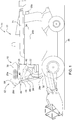
- Fig. 1 shows an embodiment of the adaptive light system according to the invention, this being described below with reference to the in Fig. 2 illustrated block diagram should be described.
- the adaptive lighting system 10 is part of a four-wheeled vehicle 14 designed as a forage harvester 14.
- the off-highway vehicle 14 can also be of any other type, conceivable inter alia being the use of the adaptive lighting system 10 in agricultural tractors, harvesting machines, forestry machines, construction machines or the like ,
- the adaptive light system 10 includes an in Fig. 2 illustrated illumination device 16, which can be controlled by an electronic control unit 18 in terms of emission characteristics and / or light intensity.
- the lighting device 16 is an environment or work lighting 20 of the forage harvester 12 and a lighting provided within a driver's cabin 22 in the form of illuminable control and display elements 24 or a cabin interior lighting 26 Fig. 1 the environment or work lights 20 a plurality of headlights 28a, 28b, 28c, 28d, 28e, which are mounted in a roof area 30 and on a front apron 32 of the cab 22 and on a body 34 of the forage harvester 12 and a flat or overlapping illumination of the field chopper 12 surrounding terrain or field surface 36 allow.
- At least the headlights 28a, 28b, 28c are individually switchable for adapting the emission characteristic and / or light intensity on the part of the control unit 18 as well as changeable in terms of their luminosity.
- On the side facing away from the viewer of the forage harvester 12 are further, corresponding to the side-mounted headlights 28a, 28b headlights.
- the headlights 28a, 28b, 28c have optical devices 38a, 38b, 38c adjacent to the actual light source (halogen or gas discharge lamp, LEDs or the like) for changing the emission characteristic, ie the emission angle or the light distribution dependent on the emission angle.
- optical devices 38a, 38b, 38c which are not shown in detail are formed either by electrically controllable optical systems (diaphragms or lens systems) or else by the luminous means itself. In the latter case, this consists of a segmented LED matrix, in which individual matrix segments on the part of the control unit 18 on and off and can be changed in terms of their luminosity. This is illustrated by way of example for the spotlight 28a arranged laterally in the roof area 30 of the driver's cab 22.
- a camera 40 for optical detection of the eye position and / or the head posture of a vehicle operator 42.
- the information thus obtained is supplied to the control unit 18 to determine the current viewing direction of the vehicle operator 42 by means of image processing software.
- the camera 40 is integrated in a rearview mirror 44 or a housing 46 surrounded by the rearview mirror 44.
- control unit 18 has a data interface 48 for the wireless reception of position information transmitted by an off-road vehicle 50 (see also FIG Fig. 3 ).
- the position information transmitted by the all-terrain vehicle 50 is located in a data cloud 52 and can be called from there via the data interface 48 via an existing mobile radio network.
- the control unit 18 determines a relative position of the forage harvester 12 relative to the off-highway foreign vehicle 50, for which purpose it performs a comparison with position information related to the forage harvester 12.
- the assessment or determination of the relative position takes place here on the basis of a polar coordinate system in which the forage harvester 12 forms the origin of the coordinates.
- the position information related to the forage harvester 12 is detected by means of a satellite-based navigation system 54.
- the satellite-based navigation system 54 is either permanently installed in the forage harvester 12 or designed as a mobile navigation unit 56. The latter is part of a mobile phone of the vehicle operator 42, wherein the determined position information is wirelessly transmitted to the control unit 18 via an LTE connection 60 produced by means of a mobile radio interface 58.
- control unit 18 is connected to an ambient light and / or image sensor 62 for determining possible extraneous light influences.
- the light and / or image sensor 62 is one in the roof area 30 of the driver's cab Notwithstanding this, it may also be arranged along an outer side of the forage harvester 12 distributed (not shown) photosensitive sensor elements or individual cameras act.
- the environment-detecting light and / or image sensor 62 makes it possible to determine the light distribution in the vicinity of the forage harvester 12, for which purpose it detects the extraneous light influences with regard to their emission characteristic and / or light intensity.
- the information determined in this way in relation to the instantaneous line of sight of the vehicle operator 42, possible extraneous light influences and / or the relative position of the off-highway foreign vehicle 50 are supplied to the control unit 18 in the form of corresponding data signals, the control unit 18 the emission characteristic and / or light intensity by driving the illumination device 16 adjusted in accordance with the information obtained.
- a first control routine executed by the control unit 18 provides for reducing the luminous intensity in areas outside the viewing direction of the vehicle operator 42 by adapting the emission characteristic and / or the light intensity of the illumination device 16.
- control unit 18 reduces the luminosity of the rear headlamp 28c, if, due to the determined line of sight, the vehicle operator 42 has not looked back for some time, which is done either by turning the head or by looking into the rearview mirror 44 can. On the other hand, the vehicle operator 42 directs his Looking back to the rear, the control unit 18 increases the luminosity of the rear headlamp 28c to its original value.
- the first control routine leads to a saving of electrical energy, since the illumination can be limited to areas lying in the attention focus of the vehicle operator 42. This is particularly important in the case of battery-operated systems, since the optimum use of the available battery capacity is of particular importance here.
- an adaptation of the emission characteristic and / or light intensity of the illumination device 16 takes place in accordance with cartographic location information.
- cartographic location information allows a targeted planning in particular of a desired illumination area of the environment or work lighting 20 along an off-road course to be traveled. It is envisaged that obstacles or danger spots (rocks, ditches and the like) are mapped and highlighted visibly upon reaching their associated position by additional illumination. The latter is performed by matching with the position information provided by the satellite-based navigation system 54. Also, the environment of the terrain to be traveled is considered to the effect that an adjacent street, localities or the like to avoid unwanted glare from the illumination of the ambient or work lighting are excluded by suitable adaptation of the emission and / or light intensity.
- the cartographic location information relevant in this respect can be recorded offline by means of a planning software and then uploaded to the control unit 18 of the adaptive light system 10.
- a third control routine executed by the control unit 18 envisages reducing the luminous intensity in areas prone to glare by adapting the emission characteristic and / or the light intensity of the illumination device 16 in order to reduce the risk of glare from off-road vehicles entering the illumination area of the forage harvester 12.
- FIG. 3 3 shows an exemplary light scene in the case of a cross-country vehicle 50 traveling next to the forage harvester 12 in the form of a vehicle combination 72 consisting of a loader wagon 68 and an agricultural tractor 70.
- a vehicle combination 72 consisting of a loader wagon 68 and an agricultural tractor 70.
- the illumination area of the Environment and work lights 20 of the forage harvester 12 is specifically expanded to the loader wagons 68.
- the control unit 18 determines from the position information received via the data interface 48 from the data cloud 52 the current relative position of the loading wagon 68 relative to the forage harvester 12 or an ejection manifold 74 provided thereon.
- the agricultural tractor 70 has its own (not shown) ) Environment or work lighting, wherein the determined by means of the ambient light and / or image sensor 62 light distribution is included by the control unit 18 in the adjustment of the emission and / or light intensity of the illumination device 16 in the general lighting situation such that on the one hand optimal or homogeneous illumination of the environment or field surface 36 in the field of forage harvester 12 ensured and on the other dazzling of a vehicle operator 76 of the agricultural tractor 70 is excluded.
- the agricultural tractor 70 is located in a darkened area 80, which is recessed by the lighting device 16 and follows the movement of the agricultural tractor 70 in accordance with the respectively determined relative position.
- control unit 18 carries out a classification of the extraneous light influences by referencing with cartographic location information, wherein an activation of the illumination device 16 is omitted insofar as it results from the classification that the extraneous light influences originate from a stationary object 80.
- a glare hazard is not given here, for example, it may be a street or courtyard lighting.
- the classification carried out allows a reliable differentiation of such extraneous light influences against those which originate from other vehicles and in which a corresponding glare hazard exists.
- the classification itself can be done by matching the cartographic location information stored in a storage unit 82 with the location information provided by the satellite-based navigation system 54.
- the three control routines may run side by side or alternatively in the control unit 18.
- a corresponding selection of the desired control routine can be made by the vehicle operator 42 via an operator terminal 84 in communication with the control unit 18, via which the headlights 28a, 28b, 28c to be included in the lighting situation can also be preselected manually.
- an automatic mode can be provided in which the illumination is adapted to the current attention focus of the vehicle operator 42 by evaluating the current viewing direction of the vehicle operator 42, so that in particular annoying manual adjustment of a desired illumination range of the ambient or working lighting 20 of the forage harvester 12 during the Fieldwork can be omitted.
- the adaptation of the lighting for the purpose the consideration of the existing residual light or other (artificial) light sources in accordance with the determined extraneous light influences modified by the control unit 18.
- the vehicle operator has the option of manually setting a desired emission characteristic and / or light intensity via the operator terminal 84.
- the control unit 18 always controls the illumination device 16 in the case of a reduction of the light intensity in such a way that a predetermined residual luminous intensity is not undershot.
- the residual luminous intensity, as well as a desired maximum luminous intensity, can be manually specified here by the vehicle operator via the operator terminal 84.
- the illustrated lighting situation is merely an illustration of the function of the adaptive lighting system in the event that several off-road vehicles drive on the same field, wherein one of the all-terrain vehicles is equipped with the adaptive lighting system.
- any other lighting situations are conceivable in which a variety of each equipped with the adaptive light system off-road vehicles forms a fleet, the individual fleet vehicles via a wireless data communication link with each other to the emission characteristics and / or light intensities associated work or To tune or adapt ambient lighting in the sense of an optimal or homogeneous illumination of a terrain surface to be processed or to avoid a mutual glare among each other.
Abstract
Adaptives Lichtsystem (10) eines geländegängigen Fahrzeugs (14), mit einer hinsichtlich Abstrahlcharakteristik und/oder Lichtintensität steuerbaren Beleuchtungseinrichtung (16) sowie einer Kontrolleinheit (18), die die Abstrahlcharakteristik und/oder Lichtintensität durch Ansteuerung der Beleuchtungseinrichtung (16) nach Maßgabe einer ermittelten Blickrichtung eines Fahrzeugbedieners (42), ermittelter Fremdlichteinflüsse, einer ermittelten Relativposition eines geländegängigen Fremdfahrzeugs (50) und/oder kartografischer Standortinformationen anpasst.Adaptive light system (10) of an off-road vehicle (14), with a controllable with respect to radiation characteristics and / or light intensity illumination device (16) and a control unit (18), the radiation characteristic and / or light intensity by controlling the illumination device (16) in accordance with a determined Viewing direction of a vehicle operator (42), determined extraneous light influences, a determined relative position of a cross-country other vehicle (50) and / or maps cartographic location information adapts.
Description
Die Erfindung betrifft ein adaptives Lichtsystem eines geländegängigen Fahrzeugs, mit einer hinsichtlich Abstrahlcharakteristik und/oder Lichtintensität steuerbaren Beleuchtungseinrichtung.The invention relates to an adaptive light system of an all-terrain vehicle, with a lighting device controllable with regard to emission characteristics and / or light intensity.
Ein derartiges Lichtsystem in Gestalt einer Vorrichtung zur Einstellung einer Beleuchtung für ein Straßenfahrzeug ist beispielsweise in der
Es ist daher Aufgabe der vorliegenden Erfindung, ein an die Anforderungen geländegängiger Fahrzeuge angepasstes adaptives Lichtsystem der eingangs genannten Art anzugeben.It is therefore an object of the present invention to provide an adapted to the requirements of off-road vehicles adaptive lighting system of the type mentioned.
Diese Aufgabe wird durch ein adaptives Lichtsystem eines geländegängigen Fahrzeugs mit den Merkmalen des Patentanspruchs 1 gelöst.This object is achieved by an adaptive lighting system of an off-road vehicle having the features of patent claim 1.
Das adaptive Lichtsystem eines geländegängigen Fahrzeugs umfasst eine hinsichtlich Abstrahlcharakteristik und/oder Lichtintensität steuerbare Beleuchtungseinrichtung sowie eine Kontrolleinheit, die die Abstrahlcharakteristik und/oder Lichtintensität durch Ansteuerung der Beleuchtungseinrichtung nach Maßgabe einer ermittelten Blickrichtung eines Fahrzeugbedieners, ermittelter Fremdlichteinflüsse, einer ermittelten Relativposition eines geländegängigen Fremdfahrzeugs und/oder kartografischer Standortinformationen anpasst.The adaptive lighting system of an off-road vehicle comprises a lighting device which is controllable with regard to emission characteristics and / or light intensity, and a control unit which determines the emission characteristic and / or light intensity by controlling the lighting device in accordance with a determined line of vision of a vehicle operator, determined extraneous light influences, an ascertained relative position of an off-road Foreign vehicle and / or cartographic location information.
Auf diese Weise lässt sich durch Auswertung der momentanen Blickrichtung des Fahrzeugbedieners die Beleuchtung dem aktuellen Aufmerksamkeitsfokus des Fahrzeugbedieners anpassen, sodass insbesondere ein lästiges manuelles Einstellen eines gewünschten Ausleuchtungsbereichs einer Umfeld- bzw. Arbeitsbeleuchtung des geländegängigen Fahrzeugs während eines Geländeeinsatzes entfallen kann, wohingegen durch Beachtung möglicher Fremdlichteinflüsse zusätzlich oder alternativ eine Berücksichtigung des vorhandenen Restlichts oder anderer (künstlicher) Lichtquellen möglich ist. Anhand der ermittelten Relativpositionen geländegängiger Fremdfahrzeuge lässt sich zudem deren möglicher Eintritt in den Ausleuchtungsbereich der Umfeld- bzw. Arbeitsbeleuchtung des geländegängigen Fahrzeugs vorhersagen, sodass sich diese in die jeweilige Beleuchtungssituation mit einbeziehen lassen. Denkbar sind hier Fälle, in denen mehrere geländegängige Fahrzeuge ein und dasselbe Terrain befahren, im Landwirtschaftsbereich zum Beispiel ein Feldhäcksler und ein neben dem Feldhäcksler herfahrender landwirtschaftlicher Traktor mit einem Ladewagen. Zur Kontrolle eines während der Fahrt durchgeführten Überladevorgangs kann hier vorgesehen sein, dass der Ausleuchtungsbereich einer Umfeld- bzw. Arbeitsbeleuchtung des Feldhäckslers gezielt auf den Ladewagen ausgeweitet wird. Daneben erlaubt die Berücksichtigung kartografischer Standortinformationen eine gezielte Planung insbesondere eines gewünschten Ausleuchtungsbereichs der Umfeld- bzw. Arbeitsbeleuchtung entlang einer zu befahrenden Geländestrecke. So kann beispielsweise vorgesehen sein, dass Hindernisse oder Gefahrenstellen (Felsen, Abzugsgräben und dergleichen) kartografisch erfasst sowie bei Erreichen ihrer zugehörigen Position durch zusätzliche Ausleuchtung sichtbar hervorgehoben werden. Auch lässt sich das Umfeld der zu befahrenden Geländestrecke dahingehend berücksichtigen, dass eine angrenzende Straße, Ortschaften oder dergleichen zur Vermeidung einer unerwünschten Blendung aus dem Ausleuchtungsbereich der Umfeld- bzw. Arbeitsbeleuchtung durch geeignete Anpassung der Abstrahlcharakteristik und/oder Lichtintensität ausgenommen werden. Die insofern relevanten kartografischen Standortinformationen können hierbei offline mittels einer Planungssoftware erfasst sowie anschließend in die Kontrolleinheit des adaptiven Lichtsystems hochgeladen werden.In this way, the lighting can be adapted to the current focus of attention of the vehicle operator by evaluating the current line of sight of the vehicle operator, so that in particular an annoying manual setting of a desired illumination area of an ambient or work lighting of the off-road vehicle during off-road use can be omitted, whereas by observing possible extraneous light influences Additionally or alternatively, a consideration of the existing residual light or other (artificial) light sources is possible. On the basis of the determined relative positions of all-terrain vehicles, their possible entry into the illumination area of the ambient or work lighting of the all-terrain vehicle can also be predicted so that they can be included in the respective lighting situation. Cases are conceivable here in which several off-road vehicles drive on one and the same terrain, in the agricultural sector, for example, a forage harvester and an agricultural tractor with a loader wagon traveling next to the forage harvester. To check a transfer operation carried out during the journey, it may be provided here that the illumination area of an environment or working lighting of the forage harvester is purposefully extended to the loader wagon. In addition, the consideration of cartographic location information permits a targeted planning, in particular of a desired illumination area of the ambient or work lighting along an off-road course to be traveled. For example, it may be provided that obstacles or danger spots (rocks, ditches and the like) are recorded in cartographic form and be visibly highlighted by additional illumination upon reaching their associated position. The surroundings of the off-road course to be traveled can also be taken into account in such a way that an adjacent street, localities or the like is excluded by suitable adaptation of the emission characteristic and / or light intensity in order to avoid unwanted glare from the illumination area of the ambient or work lighting. The cartographic location information relevant in this respect can be recorded offline by means of a planning software and then uploaded to the control unit of the adaptive lighting system.
Generell kann das geländegängige Fahrzeug von beliebiger Bauart sein, denkbar ist unter anderem eine Verwendung des adaptiven Lichtsystems in landwirtschaftlichen Traktoren, Erntemaschinen, Feldhäckslern, Forstmaschinen, Baumaschinen oder dergleichen.In general, the all-terrain vehicle may be of any type, conceivable inter alia a use of the adaptive lighting system in agricultural tractors, harvesters, forage harvesters, forestry machines, construction machinery or the like.
Vorteilhafte Weiterbildungen des erfindungsgemäßen adaptiven Lichtsystems gehen aus den Unteransprüchen hervor.Advantageous developments of the adaptive lighting system according to the invention will become apparent from the dependent claims.
Vorzugsweise handelt es sich bei der Beleuchtungseinrichtung um eine Umfeld- bzw. Arbeitsbeleuchtung des geländegängigen Fahrzeugs und/oder um eine innerhalb einer Fahrerkabine vorgesehene Beleuchtung, insbesondere in Gestalt beleuchtbarer Bedien- und Anzeigeelemente oder einer Kabineninnenraumbeleuchtung. Die Umfeld- bzw. Arbeitsbeleuchtung kann mehrere Scheinwerfer aufweisen, die unter anderem im Dachbereich der Fahrerkabine angebracht sind und eine flächige bzw. überlappende Ausleuchtung einer das geländegängige Fahrzeug umgebenden Geländeoberfläche ermöglichen. Zur Anpassung der Abstrahlcharakteristik und/oder Lichtintensität können diese einzeln schaltbar sowie hinsichtlich ihrer Leuchtstärke veränderbar sein. Hierbei ist es denkbar, dass die einzelnen Scheinwerfer neben dem eigentlichen Leuchtmittel (Halogen- bzw. Gasentladungslampen, LEDs oder dergleichen) zusätzlich optische Einrichtungen zur Veränderung der Abstrahlcharakteristik, mithin ihres Abstrahlwinkels bzw. der vom Abstrahlwinkel abhängigen Lichtverteilung aufweisen. Die optischen Einrichtungen können entweder durch elektrisch steuerbare optische Systeme (Blenden bzw. Linsensysteme) oder aber durch das Leuchtmittel selbst gebildet sein. In letzterem Fall besteht dieses typischerweise aus einer segmentierten LED-Matrix, bei der sich einzelne Matrixsegmente von Seiten der Kontrolleinheit an- und abschalten sowie bezüglich ihrer Leuchtstärke verändern lassen.The lighting device is preferably an ambient or work lighting of the all-terrain vehicle and / or a lighting provided within a driver's cab, in particular in the form of illuminable control and display elements or cabin interior lighting. The environment or work lighting may have multiple headlights, which are mounted, inter alia, in the roof area of the cab and allow a flat or overlapping illumination of the terrain vehicle surrounding terrain. To adapt the emission characteristics and / or light intensity, these can be switched individually and with regard to their luminous intensity be changeable. In this case, it is conceivable that, in addition to the actual lighting means (halogen or gas discharge lamps, LEDs or the like), the individual headlamps additionally have optical devices for changing the emission characteristic, thus their emission angle or the light distribution dependent on the emission angle. The optical devices can be formed either by electrically controllable optical systems (diaphragms or lens systems) or else by the light source itself. In the latter case, this typically consists of a segmented LED matrix in which individual matrix segments can be switched on and off by the control unit and modified in terms of their luminous intensity.
Zusätzlich kann das adaptive Lichtsystem eine von einem Anbau- oder Zusatzgeräts des geländegängigen Fahrzeugs umfasste weitere Beleuchtungseinrichtung aufweisen, insbesondere in Gestalt einer eigenen Umfeld- bzw. Arbeitsbeleuchtung. In diesem Fall wird die weitere Beleuchtungseinrichtung im Verbund mit der Beleuchtungseinrichtung des geländegängigen Fahrzeugs seitens der Kontrolleinheit derart angesteuert, dass eine gewünschte Gesamtbeleuchtungssituation erzielbar ist.In addition, the adaptive lighting system can comprise a further lighting device encompassed by an attachment or additional device of the all-terrain vehicle, in particular in the form of its own ambient or work lighting. In this case, the further illumination device in conjunction with the illumination device of the all-terrain vehicle is controlled by the control unit such that a desired overall illumination situation can be achieved.
Grundsätzlich kann die Kontrolleinheit die Leuchtstärke in außerhalb der Blickrichtung liegenden und/oder blendungsgefährdeten Bereichen durch Anpassung der Abstrahlcharakteristik und/oder Lichtintensität der Beleuchtungseinrichtung reduzieren. Auf diese Weise ist nicht nur eine Einsparung elektrischer Energie möglich, da sich die Beleuchtung auf im Aufmerksamkeitsfokus des Fahrzeugbedieners liegende Bereiche beschränken lässt, sondern es wird auch ein Blendungsrisiko von in den Ausleuchtungsbereich einer Arbeits- bzw. Umfeldbeleuchtung des geländegängigen Fahrzeugs eintretenden geländegängigen Fremdfahrzeugen vermindert, was sich anhand der ermittelten Fremdlichteinflüsse und/oder der ermittelten Relativposition des betreffenden geländegängigen Fremdfahrzeugs unschwer beurteilen lässt. Die Fremdlichteinflüsse (oder auch Streulichteinflüsse) können hierbei aufgrund eigener Umfeld- bzw. Arbeitsbeleuchtungen der geländegängigen Fremdfahrzeuge verursacht sein.In principle, the control unit can reduce the luminous intensity in areas lying outside the viewing direction and / or areas prone to glare by adapting the emission characteristic and / or the light intensity of the illumination device. In this way, not only a saving of electrical energy is possible because the lighting can be limited to lying in the attention focus of the vehicle operator areas, but it is also a risk of glare of in the illumination area of a working or ambient lighting of the off-road vehicle entrancing off-road vehicles reduced, which can be easily judged on the basis of the determined ambient light influences and / or the determined relative position of the respective off-highway foreign vehicle. The extraneous light influences (or stray light influences) can be caused here due to own environment or work lights of all-terrain vehicles.
Des Weiteren besteht die Möglichkeit, dass die Kontrolleinrichtung die Blickrichtung des Fahrzeugbedieners durch optische Erfassung der Augenstellung und/oder der Kopfhaltung ermittelt. Derartige Einrichtungen sind beispielweise aus dem Automobilbereich im Zusammenhang mit Systemen zur Einschlafwarnung bekannt und umfassen eine Kamera, die beispielsweise in einen Rückspiegel bzw. ein von dem Rückspiegel umfasstes Gehäuse innerhalb eines Fahrgastraums integriert ist, um mittels einer zugehörigen Bildverarbeitungssoftware den Müdigkeitsgrad des Fahrers aus hierfür charakteristischen Anzeichen einer erfassten Bewegung der Augenlider bzw. Pupillen abzuleiten.Furthermore, there is the possibility that the control device determines the viewing direction of the vehicle operator by optically detecting the eye position and / or the head posture. Such devices are known for example from the automotive sector in the context of systems for falling asleep and comprise a camera, which is integrated, for example, in a rearview mirror or a housing enclosed by the rearview mirror within a passenger compartment, by means of an associated image processing software, the driver's degree of fatigue of this characteristic To derive signs of sensed movement of the eyelids or pupils.
Bevorzugt weist die Kontrolleinheit eine Datenschnittstelle zum drahtlosen Empfang von seitens des geländegängigen Fremdfahrzeugs ausgesandten Positionsinformationen auf, wobei die Kontrolleinheit die Relativposition durch Vergleich mit auf das landwirtschaftliche Fahrzeug bezogenen Positionsinformationen ermittelt. Die Beurteilung bzw. Ermittlung der Relativposition erfolgt hierbei unter Zugrundelegung eines polaren Koordinatensystems, bei dem das geländegängige Fahrzeug den Koordinatenursprung bildet. Die seitens der Datenschnittstelle mit dem geländegängigen Fremdfahrzeug ausgeführte Kommunikation kann über ein vorhandenes Mobilfunknetz erfolgen, entweder unmittelbar zwischen den Fahrzeugen oder aber über einen zentralen Datenserver bzw. eine Daten-Cloud. Auch ist es möglich, dass die Kontrolleinheit die Relativposition durch optische Umgebungserfassung anhand einer mittels Bildmusterkennung durchgeführten Unterscheidung zwischen bewegten und stationären Objekten ermittelt.The control unit preferably has a data interface for the wireless reception of position information transmitted by the off-highway foreign vehicle, wherein the control unit determines the relative position by comparison with position information related to the agricultural vehicle. The assessment or determination of the relative position takes place here on the basis of a polar coordinate system in which the all-terrain vehicle forms the origin of the coordinates. The communication carried out by the data interface with the all-terrain vehicle can take place via an existing mobile radio network, either directly between the vehicles or via a central data server or a data cloud. It is also possible for the control unit to determine the relative position by optical environmental detection on the basis of a distinction between moving and stationary objects carried out by means of image pattern recognition.
Typischerweise erfolgt die Erfassung der auf das geländegängige Fahrzeug bezogenen Positionsinformationen mittels eines satellitengestützten Navigationssystems. Das satellitengestützte Navigationssystem kann hierbei fest in das landwirtschaftliche Fahrzeug eingebaut sein, es kann sich aber auch um eine mobile Navigationseinheit handeln, beispielsweise als Bestandteil eines vom Fahrzeugbediener mitgeführten Tablet-Computers, eines Mobiltelefons oder dergleichen. Hierbei werden die ermittelten Positionsinformationen zum Beispiel über eine LTE- oder WLAN-Verbindung drahtlos an die Kontrolleinheit übertragen.Typically, the detection of the off-road vehicle related position information by means of a satellite-based navigation system. The satellite-based navigation system can in this case be permanently installed in the agricultural vehicle, but it can also be a mobile navigation unit, for example as part of a tablet computer carried by the vehicle operator, a mobile telephone or the like. In this case, the determined position information is wirelessly transmitted to the control unit, for example via an LTE or WLAN connection.
Ferner ist es denkbar, dass die Kontrolleinheit die Beleuchtungseinrichtung im Falle einer Reduzierung der Lichtintensität derart ansteuert, dass eine vorgegebene Restleuchtstärke nicht unterschritten wird. Die Aufrechterhaltung einer bestimmten Restleuchtstärke verhindert gerade im Zusammenhang mit beleuchtbaren Bedien- und Anzeigeelementen, dass beim Fahrzeugbediener fälschlicherweise der Eindruck erweckt wird, die zugehörigen Funktionen seien deaktiviert bzw. inaktiv. Eine derartiger Eindruck kann sich bei vollständigem Abschalten der Instrumentenbeleuchtung ergeben. Ähnliche Betrachtungen gelten hinsichtlich des Falls, dass eine Umfeld- bzw. Arbeitsbeleuchtung des geländegängigen Fahrzeugs ausgeschaltet wird, was beim Fahrzeugbediener aufgrund des verzögerten Adaptionsvermögens des Auges zu möglichen Irritationen führen kann. Die Restleuchtstärke, wie auch eine gewünschte Höchstleuchtstärke, kann hierbei seitens des Fahrzeugbedieners manuell vorgebbar sein.Furthermore, it is conceivable that the control unit controls the illumination device in the case of a reduction of the light intensity in such a way that a predetermined residual luminosity level is not undershot. The maintenance of a certain residual luminous intensity prevents just in connection with illuminable control and display elements that the vehicle operator falsely given the impression that the associated functions are disabled or inactive. Such an impression can result when the instrument illumination is completely switched off. Similar considerations apply with respect to the case that an ambient or work lighting of the off-road vehicle is turned off, which may lead to possible irritation in the vehicle operator due to the delayed adaptability of the eye. The residual luminosity, as well as a desired Maximum luminosity, this can be specified manually by the vehicle operator.
Im einfachsten Fall steht die Kontrolleinheit zur Ermittlung der Fremdlichteinflüsse mittels eines umgebungserfassenden Licht- und/oder Bildsensors in Verbindung. Bei dem Licht- und/oder Bildsensor kann es sich entweder um eine oder mehrere im Dachbereich der Fahrerkabine angeordnete Kameras, insbesondere um eine Panorama- oder Rundumkamera, oder aber um entlang einer Außenseite des geländegängigen Fahrzeugs verteilt angeordnete lichtempfindliche Sensorelemente oder Einzelkameras handeln.In the simplest case, the control unit is responsible for determining the extraneous light influences by means of an ambient light and / or image sensor. The light and / or image sensor can either be one or more cameras arranged in the roof area of the driver's cab, in particular a panoramic or omnidirectional camera, or light-sensitive sensor elements or individual cameras arranged distributed along an outer side of the all-terrain vehicle.
Idealerweise ermöglicht der umgebungserfassende Licht- und/oder Bildsensor eine Ermittlung der Lichtverteilung im Umfeld des geländegängigen Fahrzeugs, wozu dieser die Fremdlichteinflüsse hinsichtlich Abstrahlcharakteristik und/oder Lichtintensität erfassen kann. Dies erlaubt eine besonders genaue Anpassung der Abstrahlcharakteristik und/oder Lichtintensität der Beleuchtungseinrichtung des geländegängigen Fahrzeugs, beispielsweise, um durch entsprechende Einbeziehung der ermittelten Lichtverteilung der Fremdlichteinflüsse eine gleichbleibende Ausleuchtung der Umgebung im Bereich des geländegängigen Fahrzeugs zu erzielen.Ideally, the ambient light and / or image sensor makes it possible to determine the light distribution in the surroundings of the all-terrain vehicle, for which purpose it can detect the extraneous light influences with regard to emission characteristics and / or light intensity. This allows a particularly accurate adaptation of the emission characteristic and / or light intensity of the illumination device of the all-terrain vehicle, for example, to achieve a constant illumination of the environment in the area of the all-terrain vehicle by appropriate inclusion of the determined light distribution of extraneous light influences.
Zusätzlich kann die Kontrolleinheit eine Klassifizierung der Fremdlichteinflüsse durch Referenzierung mit kartografischen Standortinformationen vornehmen, wobei eine Ansteuerung der Beleuchtungseinrichtung insofern unterbleibt, als sich aus der Klassifizierung ergibt, dass die Fremdlichteinflüsse von einem stationären Objekt ausgehen. Eine Blendungsgefährdung ist hier nicht gegeben, beispielsweise kann es sich um eine Straßen- oder Hofbeleuchtung handeln. Die durchgeführte Klassifizierung erlaubt eine verlässliche Differenzierung derartiger Fremdlichteinflüsse gegenüber solchen, die von anderen Fahrzeugen herrühren und bei denen eine entsprechende Blendungsgefährdung besteht. Die Klassifizierung selbst kann durch Abgleich der kartografischen Standortinformationen mit seitens eines satellitengestützten Navigationssystems bereitgestellten Positionsinformationen erfolgen.In addition, the control unit can make a classification of extraneous light influences by referencing with cartographic location information, wherein an activation of the illumination device is omitted insofar as it follows from the classification that the extraneous light influences originate from a stationary object. A glare hazard is not given here, for example, it may be a street or courtyard lighting. The performed classification allows a reliable differentiation of such extraneous light influences compared to those that originate from other vehicles and where there is a corresponding risk of glare. The classification itself can be done by matching the cartographic location information with position information provided by a satellite-based navigation system.
Der Vollständigkeit halber sei angemerkt, dass eine Vielzahl von jeweils mit dem adaptiven Lichtsystem ausgestatteten geländegängigen Fahrzeugen eine Flotte bilden kann, wobei die einzelnen Flottenfahrzeuge über eine drahtlose Datenkommunikationsverbindung miteinander in Austausch stehen, um die Abstrahlcharakteristiken und/oder Lichtintensitäten zugehöriger Arbeits- bzw. Umfeldbeleuchtungen im Sinne einer optimalen bzw. homogenen Ausleuchtung einer zu bearbeitenden Geländeoberfläche bzw. zur Vermeidung einer gegenseitigen Blendung untereinander abzustimmen bzw. anzupassen.For the sake of completeness, it should be noted that a variety of each equipped with the adaptive lighting system off-road vehicles can form a fleet, the individual fleet vehicles via a wireless data communication with each other in exchange to the emission characteristics and / or light intensities associated work or ambient lighting in In the sense of optimal or homogeneous illumination of a terrain surface to be processed or to avoid mutual glare with each other vote or adapt.
Das erfindungsgemäße adaptive Lichtsystem wird im Folgenden anhand der beigefügten Zeichnungen näher erläutert. Es zeigen:
- Fig. 1
- ein Ausführungsbeispiel des erfindungsgemäßen adaptiven Lichtsystems in einem geländegängigen Fahrzeug in Gestalt eines Feldhäckslers,
- Fig. 2
- ein Blockschaltbild des erfindungsgemäßen adaptiven Lichtsystems, und
- Fig. 3
- eine beispielhafte Lichtszene für den Fall eines neben dem in
Fig. 1 wiedergegebenen Feldhäcksler herfahrenden geländegängigen Fremdfahrzeugs in Gestalt eines aus einem Ladewagen sowie einem landwirtschaftlichen Traktor bestehenden Fahrzeuggespanns.
- Fig. 1
- An embodiment of the adaptive light system according to the invention in an all-terrain vehicle in the form of a forage harvester,
- Fig. 2
- a block diagram of the adaptive lighting system according to the invention, and
- Fig. 3
- an exemplary light scene in the case of one in addition to the one in
Fig. 1 reproduced forage harvester herfahren all-terrain vehicle in the form of one of a Loader and an agricultural tractor existing vehicle combination.
Beispielsgemäß ist das adaptive Lichtsystem 10 Bestandteil eines als Feldhäcksler 12 ausgebildeten geländegängigen Fahrzeugs 14. Generell kann das geländegängige Fahrzeug 14 auch von beliebiger anderer Bauart sein, denkbar ist unter anderem eine Verwendung des adaptiven Lichtsystems 10 in landwirtschaftlichen Traktoren, Erntemaschinen, Forstmaschinen, Baumaschinen oder dergleichen.By way of example, the
Das adaptive Lichtsystem 10 umfasst eine in
Genauer gesagt handelt es sich bei der Beleuchtungseinrichtung 16 um eine Umfeld- bzw. Arbeitsbeleuchtung 20 des Feldhäckslers 12 sowie um eine innerhalb einer Fahrerkabine 22 vorgesehene Beleuchtung in Gestalt beleuchtbarer Bedien- und Anzeigeelemente 24 bzw. einer Kabineninnenraumbeleuchtung 26. Gemäß
Zusätzlich weisen die Scheinwerfer 28a, 28b, 28c neben dem eigentlichen Leuchtmittel (Halogen- bzw. Gasentladungslampe, LEDs oder dergleichen) optische Einrichtungen 38a, 38b, 38c zur Veränderung der Abstrahlcharakteristik, mithin des Abstrahlwinkels bzw. der vom Abstrahlwinkel abhängigen Lichtverteilung auf. Die in
Innerhalb der Fahrerkabine 22 befindet sich eine Kamera 40 zur optischen Erfassung der Augenstellung und/oder der Kopfhaltung eines Fahrzeugbedieners 42. Die insofern gewonnenen Informationen werden der Kontrolleinheit 18 zugeführt, um mittels einer Bildverarbeitungssoftware die momentane Blickrichtung des Fahrzeugbedieners 42 zu ermitteln. Die Kamera 40 ist in einen Rückspiegel 44 bzw. ein von dem Rückspiegel 44 umfasstes Gehäuse 46 integriert.Within the driver's
Daneben weist die Kontrolleinheit 18 eine Datenschnittstelle 48 zum drahtlosen Empfang von seitens eines geländegängigen Fremdfahrzeugs 50 ausgesandten Positionsinformationen auf (siehe hierzu auch
Ausgehend von den empfangenen Positionsinformationen ermittelt die Kontrolleinheit 18 eine Relativposition des Feldhäckslers 12 gegenüber dem geländegängigen Fremdfahrzeug 50, wozu diese einen Vergleich mit auf den Feldhäcksler 12 bezogenen Positionsinformationen durchführt. Die Beurteilung bzw. Ermittlung der Relativposition erfolgt hierbei unter Zugrundelegung eines polaren Koordinatensystems, bei dem der Feldhäcksler 12 den Koordinatenursprung bildet.Based on the received position information, the
Die auf den Feldhäcksler 12 bezogenen Positionsinformation werden mittels eines satellitengestützten Navigationssystems 54 erfasst. Das satellitengestützte Navigationssystem 54 ist entweder fest in den Feldhäcksler 12 eingebaut oder aber als mobile Navigationseinheit 56 ausgebildet. Letztere ist Bestandteil eines Mobiltelefons des Fahrzeugbedieners 42, wobei die ermittelten Positionsinformationen über eine mittels einer Mobilfunk-Schnittstelle 58 hergestellten LTE-Verbindung 60 drahtlos an die Kontrolleinheit 18 übertragen werden.The position information related to the
Darüber hinaus steht die Kontrolleinheit 18 zur Ermittlung möglicher Fremdlichteinflüsse mit einem umgebungserfassenden Licht- und/oder Bildsensor 62 in Verbindung. Bei dem Licht- und/oder Bildsensor 62 handelt es sich um eine im Dachbereich 30 der Fahrerkabine 22 angeordnete Panorama- oder Rundumkamera 64. Abweichend davon kann es sich auch um entlang einer Außenseite des Feldhäckslers 12 verteilt angeordnete (nicht dargestellte) lichtempfindliche Sensorelemente oder Einzelkameras handeln.In addition, the
Der umgebungserfassende Licht- und/oder Bildsensor 62 ermöglicht eine Ermittlung der Lichtverteilung im Umfeld des Feldhäckslers 12, wozu dieser die Fremdlichteinflüsse hinsichtlich ihrer Abstrahlcharakteristik und/oder Lichtintensität erfasst.The environment-detecting light and / or
Die solchermaßen in Bezug auf die momentane Blickrichtung des Fahrzeugbedieners 42, mögliche Fremdlichteinflüsse und/oder die Relativposition des geländegängigen Fremdfahrzeugs 50 ermittelten Informationen werden der Kontrolleinheit 18 in Form entsprechender Datensignale zugeführt, wobei die Kontrolleinheit 18 die Abstrahlcharakteristik und/oder Lichtintensität durch Ansteuerung der Beleuchtungseinrichtung 16 nach Maßgabe der ermittelten Informationen anpasst.The information determined in this way in relation to the instantaneous line of sight of the
In diesem Zusammenhang sieht eine von der Kontrolleinheit 18 ausgeführte erste Steuerroutine vor, die Leuchtstärke in außerhalb der Blickrichtung des Fahrzeugbedieners 42 liegenden Bereichen durch Anpassung der Abstrahlcharakteristik und/oder der Lichtintensität der Beleuchtungseinrichtung 16 zu reduzieren.In this connection, a first control routine executed by the
So reduziert die Kontrolleinheit 18 die Leuchtstärke des rückwärtigen Scheinwerfers 28c, wenn sich aufgrund der ermittelten Blickrichtung ergibt, dass der Fahrzeugbediener 42 seit geraumer Zeit nicht mehr nach hinten geblickt hat, was entweder durch Drehen des Kopfs oder aber durch einen Blick in den Rückspiegel 44 geschehen kann. Richtet der Fahrzeugbediener 42 hingegen seinen Blick erneut nach hinten, so erhöht die Kontrolleinheit 18 die Leuchtstärke des rückwärtigen Scheinwerfers 28c auf ihren ursprünglichen Wert.Thus, the
Entsprechende Betrachtungen gelten für die Anpassung der Leuchtstärke der seitlich angeordneten Scheinwerfer 28a, 28b, wie auch der beleuchtbaren Bedien- und Anzeigeelemente 24 bzw. der Kabineninnenraumbeleuchtung 26 (sofern diese eine voneinander unabhängige Steuerung der Beleuchtung individueller Kabinenbereiche erlaubt), um störendes Streulicht innerhalb der Fahrerkabine 22 insbesondere aufgrund von Reflexionen an Glasoberflächen 66 oder dergleichen zu minimeren.Corresponding considerations apply to the adjustment of the luminous intensity of the laterally arranged
Ausgenommen hiervon sind aus Gründen der Fahrtsicherheit die in Fahrtrichtung orientierten Frontscheinwerfer 28d, 28e des Feldhäckslers 12.Excluded from this are, for driving safety reasons, the headlights oriented in the direction of
Im Ergebnis führt die erste Steuerroutine zu einer Einsparung elektrischer Energie, da sich die Beleuchtung auf im Aufmerksamkeitsfokus des Fahrzeugbedieners 42 liegende Bereiche beschränken lässt. Dies ist insbesondere im Falle batteriebetriebener Systeme von Bedeutung, da hier der optimalen Nutzung der zur Verfügung stehenden Batteriekapazität eine besondere Bedeutung zukommt.As a result, the first control routine leads to a saving of electrical energy, since the illumination can be limited to areas lying in the attention focus of the
Im Falle einer von der Kontrolleinheit 18 ausgeführten zweiten Steuerroutine erfolgt eine Anpassung der Abstrahlcharakteristik und/oder Lichtintensität der Beleuchtungseinrichtung 16 nach Maßgabe kartografischer Standortinformationen. Die Berücksichtigung kartografischer Standortinformationen erlaubt eine gezielte Planung insbesondere eines gewünschten Ausleuchtungsbereichs der Umfeld- bzw. Arbeitsbeleuchtung 20 entlang einer zu befahrenden Geländestrecke. So ist vorgesehen, dass Hindernisse oder Gefahrenstellen (Felsen, Abzugsgräben und dergleichen) kartografisch erfasst sowie bei Erreichen ihrer zugehörigen Position durch zusätzliche Ausleuchtung sichtbar hervorgehoben werden. Letzteres wird durch Abgleich mit den seitens des satellitengestützten Navigationssystems 54 bereitgestellten Positionsinformationen durchgeführt. Auch wird das Umfeld der zu befahrenden Geländestrecke dahingehend berücksichtigt, dass eine angrenzende Straße, Ortschaften oder dergleichen zur Vermeidung einer unerwünschten Blendung aus dem Ausleuchtungsbereich der Umfeld- bzw. Arbeitsbeleuchtung durch geeignete Anpassung der Abstrahlcharakteristik und/oder Lichtintensität ausgenommen werden. Die insofern relevanten kartografischen Standortinformationen können hierbei offline mittels einer Planungssoftware erfasst sowie anschließend in die Kontrolleinheit 18 des adaptiven Lichtsystems 10 hochgeladen werden.In the case of a second control routine executed by the
Eine von der Kontrolleinheit 18 ausgeführte dritte Steuerroutine sieht vor, die Leuchtstärke in blendungsgefährdeten Bereichen durch Anpassung der Abstrahlcharakteristik und/oder der Lichtintensität der Beleuchtungseinrichtung 16 zu reduzieren, um ein Blendungsrisiko von in den Ausleuchtungsbereich des Feldhäckslers 12 eintretenden geländegängigen Fremdfahrzeugen zu vermindern.A third control routine executed by the
Eine derartige Beleuchtungssituation ist in
Zu diesem Zweck bestimmt die Kontrolleinheit 18 aus den über die Datenschnittstelle 48 aus der Daten-Cloud 52 empfangenen Positionsinformationen die aktuelle Relativposition des Ladewagens 68 gegenüber dem Feldhäcksler 12 bzw. einem an diesem vorgesehenen Auswurfkrümmer 74. Der landwirtschaftliche Traktor 70 weist eine eigene (nicht dargestellte) Umfeld- bzw. Arbeitsbeleuchtung auf, wobei die mittels des umgebungserfassenden Licht- und/oder Bildsensors 62 ermittelte Lichtverteilung von der Kontrolleinheit 18 bei der Anpassung der Abstrahlcharakteristik und/oder Lichtintensität der Beleuchtungseinrichtung 16 derart in die allgemeine Beleuchtungssituation einbezogen wird, dass zum einen eine optimale bzw. homogene Ausleuchtung der Umgebung bzw. Feldoberfläche 36 im Bereich des Feldhäckslers 12 sichergestellt und zum anderen eine Blendung eines Fahrzeugbedieners 76 des landwirtschaftlichen Traktors 70 ausgeschlossen ist. Der landwirtschaftliche Traktor 70 befindet sich anschaulich gesprochen in einem von der Beleuchtungseinrichtung 16 ausgesparten abgedunkelten Bereich 80, der der Bewegung des landwirtschaftlichen Traktors 70 entsprechend der jeweils ermittelten Relativposition folgt. Dies gilt insbesondere auch für den Fall, dass das abgebildete Fahrzeuggespann 72 nach dem Befüllen des Ladewagens 68 wegfährt sowie ein neues Fahrzeuggespann mit leerem Ladewagen an den Feldhäcksler 12 heranfährt und in den Ausleuchtungsbereich der Umfeld- bzw. Arbeitsbeleuchtung 20 des Feldhäckslers 12 eintritt, was sich anhand der für das neue Fahrzeuggespann ermittelten Relativposition vorhersagen lässt.For this purpose, the
Zusätzlich nimmt die Kontrolleinheit 18 eine Klassifizierung der Fremdlichteinflüsse durch Referenzierung mit kartografischen Standortinformationen vor, wobei eine Ansteuerung der Beleuchtungseinrichtung 16 insofern unterbleibt, als sich aus der Klassifizierung ergibt, dass die Fremdlichteinflüsse von einem stationären Objekt 80 ausgehen. Eine Blendungsgefährdung ist hier nicht gegeben, beispielsweise kann es sich um eine Straßen- oder Hofbeleuchtung handeln. Die durchgeführte Klassifizierung erlaubt eine verlässliche Differenzierung derartiger Fremdlichteinflüsse gegenüber solchen, die von anderen Fahrzeugen herrühren und bei denen eine entsprechende Blendungsgefährdung besteht. Die Klassifizierung selbst kann durch Abgleich der in einer Speichereinheit 82 abgelegten kartografischen Standortinformationen mit den seitens des satellitengestützten Navigationssystems 54 bereitgestellten Positionsinformationen erfolgen.In addition, the
Die drei Steuerroutinen können nebeneinander oder alternativ zueinander in der Kontrolleinheit 18 ablaufen. Eine entsprechende Auswahl der gewünschten Steuerroutine kann der Fahrzeugbediener 42 über ein mit der Kontrolleinheit 18 in Verbindung stehendes Bedienerterminal 84 treffen, über das sich auch die in die Beleuchtungssituation einzubeziehenden Scheinwerfer 28a, 28b, 28c manuell vorauswählen lassen. Daneben kann auch ein Automatikmodus vorgesehen sein, in dem durch Auswertung der momentanen Blickrichtung des Fahrzeugbedieners 42 die Beleuchtung dem aktuellen Aufmerksamkeitsfokus des Fahrzeugbedieners 42 angepasst wird, sodass insbesondere ein lästiges manuelles Einstellen eines gewünschten Ausleuchtungsbereichs der Umfeld- bzw. Arbeitsbeleuchtung 20 des Feldhäckslers 12 während der Feldbearbeitung entfallen kann. Hierbei wird die Anpassung der Beleuchtung zum Zwecke der Berücksichtigung des vorhandenen Restlichts oder anderer (künstlicher) Lichtquellen nach Maßgabe der ermittelten Fremdlichteinflüsse von der Kontrolleinheit 18 modifiziert.The three control routines may run side by side or alternatively in the
Wird der Automatikmodus abgeschaltet, so hat der Fahrzeugbediener die Möglichkeit, über das Bedienerterminal 84 eine gewünschte Abstrahlcharakteristik und/oder Lichtintensität manuell einzustellen.If the automatic mode is switched off, the vehicle operator has the option of manually setting a desired emission characteristic and / or light intensity via the
Ungeachtet der jeweiligen Steuerroutine steuert die Kontrolleinheit 18 die Beleuchtungseinrichtung 16 im Falle einer Reduzierung der Lichtintensität stets derart an, dass eine vorgegebene Restleuchtstärke nicht unterschritten wird. Die Restleuchtstärke, wie auch eine gewünschte Höchstleuchtstärke, ist hierbei seitens des Fahrzeugbedieners über das Bedienerterminal 84 manuell vorgebbar.Irrespective of the respective control routine, the
Die in
Claims (11)
Applications Claiming Priority (2)
| Application Number | Priority Date | Filing Date | Title |
|---|---|---|---|
| DE102017202808 | 2017-02-21 | ||
| DE102017205467.0A DE102017205467A1 (en) | 2017-02-21 | 2017-03-30 | Adaptive light system of an off-road vehicle |
Publications (2)
| Publication Number | Publication Date |
|---|---|
| EP3363684A1 true EP3363684A1 (en) | 2018-08-22 |
| EP3363684B1 EP3363684B1 (en) | 2021-12-08 |
Family
ID=61132021
Family Applications (1)
| Application Number | Title | Priority Date | Filing Date |
|---|---|---|---|
| EP18154059.2A Active EP3363684B1 (en) | 2017-02-21 | 2018-01-30 | Adaptive light system of an off-road vehicle |
Country Status (1)
| Country | Link |
|---|---|
| EP (1) | EP3363684B1 (en) |
Cited By (6)
| Publication number | Priority date | Publication date | Assignee | Title |
|---|---|---|---|---|
| EP3483006A1 (en) * | 2017-11-10 | 2019-05-15 | HELLA GmbH & Co. KGaA | Work lighting system for a working machine and working machine with the work lighting system |
| IT201800010490A1 (en) * | 2018-11-21 | 2020-05-21 | Prinoth Spa | TRACKED VEHICLE FOR SKI SLOPES AND METHOD OF DISPLAYING INFORMATION FOR SUCH TRACKED VEHICLE |
| EP3903559A1 (en) * | 2020-04-30 | 2021-11-03 | Deere & Company | Implement recognition lighting |
| EP3957522A1 (en) * | 2020-08-20 | 2022-02-23 | CLAAS Selbstfahrende Erntemaschinen GmbH | Agricultural work machine and method for operating same |
| US20220186465A1 (en) * | 2019-03-26 | 2022-06-16 | Kobelco Construction Machinery Co., Ltd. | Remote operation system and remote operation server |
| US11444697B2 (en) | 2020-02-28 | 2022-09-13 | Deere & Company | Method for communication between two utility vehicles |
Citations (5)
| Publication number | Priority date | Publication date | Assignee | Title |
|---|---|---|---|---|
| DE102005036002A1 (en) * | 2005-08-01 | 2007-02-08 | GM Global Technology Operations, Inc., Detroit | Method for controlling the illumination device of a vehicle, headlight system and processing device |
| EP2158799A1 (en) * | 2008-08-27 | 2010-03-03 | CLAAS Tractor S.A.S. | Self-propelled agricultural working machine |
| EP2415637A1 (en) * | 2010-08-03 | 2012-02-08 | Deere & Company | Control device for a vehicle headlamp system |
| US20130286671A1 (en) * | 2012-04-27 | 2013-10-31 | Scott J Breiner | Adaptive work light and drive light intensity for a work vehicle |
| US20140211488A1 (en) * | 2014-03-31 | 2014-07-31 | Caterpillar Inc. | Method to control headlight of vehicle |
-
2018
- 2018-01-30 EP EP18154059.2A patent/EP3363684B1/en active Active
Patent Citations (5)
| Publication number | Priority date | Publication date | Assignee | Title |
|---|---|---|---|---|
| DE102005036002A1 (en) * | 2005-08-01 | 2007-02-08 | GM Global Technology Operations, Inc., Detroit | Method for controlling the illumination device of a vehicle, headlight system and processing device |
| EP2158799A1 (en) * | 2008-08-27 | 2010-03-03 | CLAAS Tractor S.A.S. | Self-propelled agricultural working machine |
| EP2415637A1 (en) * | 2010-08-03 | 2012-02-08 | Deere & Company | Control device for a vehicle headlamp system |
| US20130286671A1 (en) * | 2012-04-27 | 2013-10-31 | Scott J Breiner | Adaptive work light and drive light intensity for a work vehicle |
| US20140211488A1 (en) * | 2014-03-31 | 2014-07-31 | Caterpillar Inc. | Method to control headlight of vehicle |
Cited By (10)
| Publication number | Priority date | Publication date | Assignee | Title |
|---|---|---|---|---|
| EP3483006A1 (en) * | 2017-11-10 | 2019-05-15 | HELLA GmbH & Co. KGaA | Work lighting system for a working machine and working machine with the work lighting system |
| US10427589B2 (en) | 2017-11-10 | 2019-10-01 | HELLA GmbH & Co. KGaA | Work lighting for a machine, and machine having the work lighting |
| IT201800010490A1 (en) * | 2018-11-21 | 2020-05-21 | Prinoth Spa | TRACKED VEHICLE FOR SKI SLOPES AND METHOD OF DISPLAYING INFORMATION FOR SUCH TRACKED VEHICLE |
| WO2020104997A1 (en) * | 2018-11-21 | 2020-05-28 | Prinoth S.P.A. | Crawler vehicle for ski runs and method of displaying information for such a snow crawler vehicle |
| US20220186465A1 (en) * | 2019-03-26 | 2022-06-16 | Kobelco Construction Machinery Co., Ltd. | Remote operation system and remote operation server |
| US11732440B2 (en) * | 2019-03-26 | 2023-08-22 | Kobelco Construction Machinery Co., Ltd. | Remote operation system and remote operation server |
| US11444697B2 (en) | 2020-02-28 | 2022-09-13 | Deere & Company | Method for communication between two utility vehicles |
| EP3903559A1 (en) * | 2020-04-30 | 2021-11-03 | Deere & Company | Implement recognition lighting |
| US11827286B2 (en) | 2020-04-30 | 2023-11-28 | Deere & Company | Implement recognition lighting |
| EP3957522A1 (en) * | 2020-08-20 | 2022-02-23 | CLAAS Selbstfahrende Erntemaschinen GmbH | Agricultural work machine and method for operating same |
Also Published As
| Publication number | Publication date |
|---|---|
| EP3363684B1 (en) | 2021-12-08 |
Similar Documents
| Publication | Publication Date | Title |
|---|---|---|
| DE102017205467A1 (en) | Adaptive light system of an off-road vehicle | |
| EP3363684B1 (en) | Adaptive light system of an off-road vehicle | |
| EP2864157B1 (en) | Method for automatically adapting vehicle lighting to a surrounding area of a vehicle, lighting apparatus and vehicle having lighting | |
| WO2009074671A1 (en) | Method and system for adjusting a vehicle | |
| EP1668386B1 (en) | Method for improving vision in a motor vehicle | |
| EP2819870B1 (en) | Method and device for detecting dazzling of the driver of a vehicle | |
| DE102018206759B4 (en) | VEHICLE HEADLIGHT SYSTEM AND METHOD FOR CONTROLLING THE SAME | |
| WO2004047449A1 (en) | Device and method for improving visibility in a motor vehicle | |
| DE102014213131A1 (en) | Method and control device for controlling at least one lighting system of a vehicle | |
| DE112017006833T5 (en) | VEHICLE LIGHTING SYSTEM | |
| DE102011081432A1 (en) | Method and control unit for adjusting a luminous intensity of at least one headlight of a vehicle | |
| DE102014225803A1 (en) | Recognition of a used emergency vehicle in traffic | |
| DE102010038961A1 (en) | Method for determination of recommendation for e.g. beam path of headlight of passenger car, involves evaluating combined travel data for determining recommendation for radiation characteristics of headlight of vehicle | |
| DE102016223232A1 (en) | Motor vehicle with automatic driving light control | |
| DE102014019420A1 (en) | Motor vehicle headlight system, motor vehicle, method for operating a motor vehicle headlight system and computer program product | |
| WO2019120774A1 (en) | Method for assisting a driver of a motor vehicle during an overtaking operation, motor vehicle, and system | |
| DE102019122254A1 (en) | CONTROL OF VEHICLE FRONT HEADLIGHTS BASED ON WEATHER CONDITIONS | |
| DE212013000187U1 (en) | System Image of an outdoor scene using an application-specific image sensor | |
| DE102017202466B4 (en) | Controlling a headlamp of a motor vehicle | |
| DE102018201285A1 (en) | Motor vehicle headlight system, method for operating a motor vehicle headlight system | |
| EP3548335B1 (en) | Controlling a controllable headlight of a motor vehicle | |
| DE102020102671A1 (en) | SPEED-BASED DARK MODE FOR POLICE VEHICLES | |
| EP3483006A1 (en) | Work lighting system for a working machine and working machine with the work lighting system | |
| EP3856557B1 (en) | Method for detecting light conditions in a vehicle | |
| DE102017214496B4 (en) | Motor vehicle with at least one light source |
Legal Events
| Date | Code | Title | Description |
|---|---|---|---|
| PUAI | Public reference made under article 153(3) epc to a published international application that has entered the european phase |
Free format text: ORIGINAL CODE: 0009012 |
|
| STAA | Information on the status of an ep patent application or granted ep patent |
Free format text: STATUS: THE APPLICATION HAS BEEN PUBLISHED |
|
| AK | Designated contracting states |
Kind code of ref document: A1 Designated state(s): AL AT BE BG CH CY CZ DE DK EE ES FI FR GB GR HR HU IE IS IT LI LT LU LV MC MK MT NL NO PL PT RO RS SE SI SK SM TR |
|
| AX | Request for extension of the european patent |
Extension state: BA ME |
|
| STAA | Information on the status of an ep patent application or granted ep patent |
Free format text: STATUS: REQUEST FOR EXAMINATION WAS MADE |
|
| 17P | Request for examination filed |
Effective date: 20190222 |
|
| RBV | Designated contracting states (corrected) |
Designated state(s): AL AT BE BG CH CY CZ DE DK EE ES FI FR GB GR HR HU IE IS IT LI LT LU LV MC MK MT NL NO PL PT RO RS SE SI SK SM TR |
|
| STAA | Information on the status of an ep patent application or granted ep patent |
Free format text: STATUS: REQUEST FOR EXAMINATION WAS MADE |
|
| GRAP | Despatch of communication of intention to grant a patent |
Free format text: ORIGINAL CODE: EPIDOSNIGR1 |
|
| STAA | Information on the status of an ep patent application or granted ep patent |
Free format text: STATUS: GRANT OF PATENT IS INTENDED |
|
| INTG | Intention to grant announced |
Effective date: 20210723 |
|
| GRAS | Grant fee paid |
Free format text: ORIGINAL CODE: EPIDOSNIGR3 |
|
| GRAA | (expected) grant |
Free format text: ORIGINAL CODE: 0009210 |
|
| STAA | Information on the status of an ep patent application or granted ep patent |
Free format text: STATUS: THE PATENT HAS BEEN GRANTED |
|
| AK | Designated contracting states |
Kind code of ref document: B1 Designated state(s): AL AT BE BG CH CY CZ DE DK EE ES FI FR GB GR HR HU IE IS IT LI LT LU LV MC MK MT NL NO PL PT RO RS SE SI SK SM TR |
|
| REG | Reference to a national code |
Ref country code: GB Ref legal event code: FG4D Free format text: NOT ENGLISH |
|
| REG | Reference to a national code |
Ref country code: AT Ref legal event code: REF Ref document number: 1453531 Country of ref document: AT Kind code of ref document: T Effective date: 20211215 Ref country code: CH Ref legal event code: EP |
|
| REG | Reference to a national code |
Ref country code: DE Ref legal event code: R096 Ref document number: 502018008086 Country of ref document: DE |
|
| REG | Reference to a national code |
Ref country code: IE Ref legal event code: FG4D Free format text: LANGUAGE OF EP DOCUMENT: GERMAN |
|
| REG | Reference to a national code |
Ref country code: FI Ref legal event code: FGE |
|
| REG | Reference to a national code |
Ref country code: LT Ref legal event code: MG9D |
|
| REG | Reference to a national code |
Ref country code: NL Ref legal event code: MP Effective date: 20211208 |
|
| PG25 | Lapsed in a contracting state [announced via postgrant information from national office to epo] |
Ref country code: RS Free format text: LAPSE BECAUSE OF FAILURE TO SUBMIT A TRANSLATION OF THE DESCRIPTION OR TO PAY THE FEE WITHIN THE PRESCRIBED TIME-LIMIT Effective date: 20211208 Ref country code: LT Free format text: LAPSE BECAUSE OF FAILURE TO SUBMIT A TRANSLATION OF THE DESCRIPTION OR TO PAY THE FEE WITHIN THE PRESCRIBED TIME-LIMIT Effective date: 20211208 Ref country code: BG Free format text: LAPSE BECAUSE OF FAILURE TO SUBMIT A TRANSLATION OF THE DESCRIPTION OR TO PAY THE FEE WITHIN THE PRESCRIBED TIME-LIMIT Effective date: 20220308 |
|
| PG25 | Lapsed in a contracting state [announced via postgrant information from national office to epo] |
Ref country code: SE Free format text: LAPSE BECAUSE OF FAILURE TO SUBMIT A TRANSLATION OF THE DESCRIPTION OR TO PAY THE FEE WITHIN THE PRESCRIBED TIME-LIMIT Effective date: 20211208 Ref country code: NO Free format text: LAPSE BECAUSE OF FAILURE TO SUBMIT A TRANSLATION OF THE DESCRIPTION OR TO PAY THE FEE WITHIN THE PRESCRIBED TIME-LIMIT Effective date: 20220308 Ref country code: LV Free format text: LAPSE BECAUSE OF FAILURE TO SUBMIT A TRANSLATION OF THE DESCRIPTION OR TO PAY THE FEE WITHIN THE PRESCRIBED TIME-LIMIT Effective date: 20211208 Ref country code: HR Free format text: LAPSE BECAUSE OF FAILURE TO SUBMIT A TRANSLATION OF THE DESCRIPTION OR TO PAY THE FEE WITHIN THE PRESCRIBED TIME-LIMIT Effective date: 20211208 Ref country code: GR Free format text: LAPSE BECAUSE OF FAILURE TO SUBMIT A TRANSLATION OF THE DESCRIPTION OR TO PAY THE FEE WITHIN THE PRESCRIBED TIME-LIMIT Effective date: 20220309 Ref country code: ES Free format text: LAPSE BECAUSE OF FAILURE TO SUBMIT A TRANSLATION OF THE DESCRIPTION OR TO PAY THE FEE WITHIN THE PRESCRIBED TIME-LIMIT Effective date: 20211208 |
|
| PG25 | Lapsed in a contracting state [announced via postgrant information from national office to epo] |
Ref country code: NL Free format text: LAPSE BECAUSE OF FAILURE TO SUBMIT A TRANSLATION OF THE DESCRIPTION OR TO PAY THE FEE WITHIN THE PRESCRIBED TIME-LIMIT Effective date: 20211208 |
|
| PG25 | Lapsed in a contracting state [announced via postgrant information from national office to epo] |
Ref country code: SM Free format text: LAPSE BECAUSE OF FAILURE TO SUBMIT A TRANSLATION OF THE DESCRIPTION OR TO PAY THE FEE WITHIN THE PRESCRIBED TIME-LIMIT Effective date: 20211208 Ref country code: SK Free format text: LAPSE BECAUSE OF FAILURE TO SUBMIT A TRANSLATION OF THE DESCRIPTION OR TO PAY THE FEE WITHIN THE PRESCRIBED TIME-LIMIT Effective date: 20211208 Ref country code: RO Free format text: LAPSE BECAUSE OF FAILURE TO SUBMIT A TRANSLATION OF THE DESCRIPTION OR TO PAY THE FEE WITHIN THE PRESCRIBED TIME-LIMIT Effective date: 20211208 Ref country code: PT Free format text: LAPSE BECAUSE OF FAILURE TO SUBMIT A TRANSLATION OF THE DESCRIPTION OR TO PAY THE FEE WITHIN THE PRESCRIBED TIME-LIMIT Effective date: 20220408 Ref country code: EE Free format text: LAPSE BECAUSE OF FAILURE TO SUBMIT A TRANSLATION OF THE DESCRIPTION OR TO PAY THE FEE WITHIN THE PRESCRIBED TIME-LIMIT Effective date: 20211208 Ref country code: CZ Free format text: LAPSE BECAUSE OF FAILURE TO SUBMIT A TRANSLATION OF THE DESCRIPTION OR TO PAY THE FEE WITHIN THE PRESCRIBED TIME-LIMIT Effective date: 20211208 |
|
| PG25 | Lapsed in a contracting state [announced via postgrant information from national office to epo] |
Ref country code: PL Free format text: LAPSE BECAUSE OF FAILURE TO SUBMIT A TRANSLATION OF THE DESCRIPTION OR TO PAY THE FEE WITHIN THE PRESCRIBED TIME-LIMIT Effective date: 20211208 |
|
| REG | Reference to a national code |
Ref country code: CH Ref legal event code: PL |
|
| REG | Reference to a national code |
Ref country code: DE Ref legal event code: R097 Ref document number: 502018008086 Country of ref document: DE |
|
| PG25 | Lapsed in a contracting state [announced via postgrant information from national office to epo] |
Ref country code: MC Free format text: LAPSE BECAUSE OF FAILURE TO SUBMIT A TRANSLATION OF THE DESCRIPTION OR TO PAY THE FEE WITHIN THE PRESCRIBED TIME-LIMIT Effective date: 20211208 Ref country code: IS Free format text: LAPSE BECAUSE OF FAILURE TO SUBMIT A TRANSLATION OF THE DESCRIPTION OR TO PAY THE FEE WITHIN THE PRESCRIBED TIME-LIMIT Effective date: 20220408 |
|
| REG | Reference to a national code |
Ref country code: BE Ref legal event code: MM Effective date: 20220131 |
|
| PLBE | No opposition filed within time limit |
Free format text: ORIGINAL CODE: 0009261 |
|
| STAA | Information on the status of an ep patent application or granted ep patent |
Free format text: STATUS: NO OPPOSITION FILED WITHIN TIME LIMIT |
|
| PG25 | Lapsed in a contracting state [announced via postgrant information from national office to epo] |
Ref country code: LU Free format text: LAPSE BECAUSE OF NON-PAYMENT OF DUE FEES Effective date: 20220130 Ref country code: DK Free format text: LAPSE BECAUSE OF FAILURE TO SUBMIT A TRANSLATION OF THE DESCRIPTION OR TO PAY THE FEE WITHIN THE PRESCRIBED TIME-LIMIT Effective date: 20211208 Ref country code: AL Free format text: LAPSE BECAUSE OF FAILURE TO SUBMIT A TRANSLATION OF THE DESCRIPTION OR TO PAY THE FEE WITHIN THE PRESCRIBED TIME-LIMIT Effective date: 20211208 |
|
| 26N | No opposition filed |
Effective date: 20220909 |
|
| PG25 | Lapsed in a contracting state [announced via postgrant information from national office to epo] |
Ref country code: SI Free format text: LAPSE BECAUSE OF FAILURE TO SUBMIT A TRANSLATION OF THE DESCRIPTION OR TO PAY THE FEE WITHIN THE PRESCRIBED TIME-LIMIT Effective date: 20211208 Ref country code: BE Free format text: LAPSE BECAUSE OF NON-PAYMENT OF DUE FEES Effective date: 20220131 |
|
| PG25 | Lapsed in a contracting state [announced via postgrant information from national office to epo] |
Ref country code: LI Free format text: LAPSE BECAUSE OF NON-PAYMENT OF DUE FEES Effective date: 20220131 Ref country code: CH Free format text: LAPSE BECAUSE OF NON-PAYMENT OF DUE FEES Effective date: 20220131 |
|
| PG25 | Lapsed in a contracting state [announced via postgrant information from national office to epo] |
Ref country code: IE Free format text: LAPSE BECAUSE OF NON-PAYMENT OF DUE FEES Effective date: 20220130 |
|
| PGFP | Annual fee paid to national office [announced via postgrant information from national office to epo] |
Ref country code: FR Payment date: 20230125 Year of fee payment: 6 Ref country code: FI Payment date: 20230127 Year of fee payment: 6 Ref country code: AT Payment date: 20230103 Year of fee payment: 6 |
|
| PGFP | Annual fee paid to national office [announced via postgrant information from national office to epo] |
Ref country code: IT Payment date: 20230120 Year of fee payment: 6 Ref country code: GB Payment date: 20230127 Year of fee payment: 6 Ref country code: DE Payment date: 20221221 Year of fee payment: 6 |
|
| PG25 | Lapsed in a contracting state [announced via postgrant information from national office to epo] |
Ref country code: HU Free format text: LAPSE BECAUSE OF FAILURE TO SUBMIT A TRANSLATION OF THE DESCRIPTION OR TO PAY THE FEE WITHIN THE PRESCRIBED TIME-LIMIT; INVALID AB INITIO Effective date: 20180130 |