EP3363662A1 - Suspension system - Google Patents
Suspension system Download PDFInfo
- Publication number
- EP3363662A1 EP3363662A1 EP18156009.5A EP18156009A EP3363662A1 EP 3363662 A1 EP3363662 A1 EP 3363662A1 EP 18156009 A EP18156009 A EP 18156009A EP 3363662 A1 EP3363662 A1 EP 3363662A1
- Authority
- EP
- European Patent Office
- Prior art keywords
- control arm
- upper control
- subframe
- steering knuckle
- axis
- Prior art date
- Legal status (The legal status is an assumption and is not a legal conclusion. Google has not performed a legal analysis and makes no representation as to the accuracy of the status listed.)
- Granted
Links
Images


Classifications
-
- B—PERFORMING OPERATIONS; TRANSPORTING
- B62—LAND VEHICLES FOR TRAVELLING OTHERWISE THAN ON RAILS
- B62D—MOTOR VEHICLES; TRAILERS
- B62D21/00—Understructures, i.e. chassis frame on which a vehicle body may be mounted
- B62D21/11—Understructures, i.e. chassis frame on which a vehicle body may be mounted with resilient means for suspension, e.g. of wheels or engine; sub-frames for mounting engine or suspensions
-
- B—PERFORMING OPERATIONS; TRANSPORTING
- B60—VEHICLES IN GENERAL
- B60G—VEHICLE SUSPENSION ARRANGEMENTS
- B60G11/00—Resilient suspensions characterised by arrangement, location or kind of springs
- B60G11/26—Resilient suspensions characterised by arrangement, location or kind of springs having fluid springs only, e.g. hydropneumatic springs
- B60G11/27—Resilient suspensions characterised by arrangement, location or kind of springs having fluid springs only, e.g. hydropneumatic springs wherein the fluid is a gas
-
- B—PERFORMING OPERATIONS; TRANSPORTING
- B60—VEHICLES IN GENERAL
- B60G—VEHICLE SUSPENSION ARRANGEMENTS
- B60G11/00—Resilient suspensions characterised by arrangement, location or kind of springs
- B60G11/26—Resilient suspensions characterised by arrangement, location or kind of springs having fluid springs only, e.g. hydropneumatic springs
- B60G11/28—Resilient suspensions characterised by arrangement, location or kind of springs having fluid springs only, e.g. hydropneumatic springs characterised by means specially adapted for attaching the spring to axle or sprung part of the vehicle
-
- B—PERFORMING OPERATIONS; TRANSPORTING
- B60—VEHICLES IN GENERAL
- B60G—VEHICLE SUSPENSION ARRANGEMENTS
- B60G15/00—Resilient suspensions characterised by arrangement, location or type of combined spring and vibration damper, e.g. telescopic type
- B60G15/08—Resilient suspensions characterised by arrangement, location or type of combined spring and vibration damper, e.g. telescopic type having fluid spring
- B60G15/12—Resilient suspensions characterised by arrangement, location or type of combined spring and vibration damper, e.g. telescopic type having fluid spring and fluid damper
-
- B—PERFORMING OPERATIONS; TRANSPORTING
- B60—VEHICLES IN GENERAL
- B60G—VEHICLE SUSPENSION ARRANGEMENTS
- B60G3/00—Resilient suspensions for a single wheel
- B60G3/18—Resilient suspensions for a single wheel with two or more pivoted arms, e.g. parallelogram
- B60G3/20—Resilient suspensions for a single wheel with two or more pivoted arms, e.g. parallelogram all arms being rigid
-
- B—PERFORMING OPERATIONS; TRANSPORTING
- B60—VEHICLES IN GENERAL
- B60G—VEHICLE SUSPENSION ARRANGEMENTS
- B60G7/00—Pivoted suspension arms; Accessories thereof
- B60G7/001—Suspension arms, e.g. constructional features
-
- B—PERFORMING OPERATIONS; TRANSPORTING
- B60—VEHICLES IN GENERAL
- B60G—VEHICLE SUSPENSION ARRANGEMENTS
- B60G7/00—Pivoted suspension arms; Accessories thereof
- B60G7/02—Attaching arms to sprung part of vehicle
-
- B—PERFORMING OPERATIONS; TRANSPORTING
- B62—LAND VEHICLES FOR TRAVELLING OTHERWISE THAN ON RAILS
- B62D—MOTOR VEHICLES; TRAILERS
- B62D7/00—Steering linkage; Stub axles or their mountings
- B62D7/06—Steering linkage; Stub axles or their mountings for individually-pivoted wheels, e.g. on king-pins
-
- B—PERFORMING OPERATIONS; TRANSPORTING
- B62—LAND VEHICLES FOR TRAVELLING OTHERWISE THAN ON RAILS
- B62D—MOTOR VEHICLES; TRAILERS
- B62D7/00—Steering linkage; Stub axles or their mountings
- B62D7/18—Steering knuckles; King pins
-
- B—PERFORMING OPERATIONS; TRANSPORTING
- B60—VEHICLES IN GENERAL
- B60G—VEHICLE SUSPENSION ARRANGEMENTS
- B60G2200/00—Indexing codes relating to suspension types
- B60G2200/10—Independent suspensions
- B60G2200/14—Independent suspensions with lateral arms
-
- B—PERFORMING OPERATIONS; TRANSPORTING
- B60—VEHICLES IN GENERAL
- B60G—VEHICLE SUSPENSION ARRANGEMENTS
- B60G2200/00—Indexing codes relating to suspension types
- B60G2200/10—Independent suspensions
- B60G2200/14—Independent suspensions with lateral arms
- B60G2200/144—Independent suspensions with lateral arms with two lateral arms forming a parallelogram
-
- B—PERFORMING OPERATIONS; TRANSPORTING
- B60—VEHICLES IN GENERAL
- B60G—VEHICLE SUSPENSION ARRANGEMENTS
- B60G2200/00—Indexing codes relating to suspension types
- B60G2200/10—Independent suspensions
- B60G2200/14—Independent suspensions with lateral arms
- B60G2200/156—Independent suspensions with lateral arms wishbone-type arm formed by two links defining a virtual apex
-
- B—PERFORMING OPERATIONS; TRANSPORTING
- B60—VEHICLES IN GENERAL
- B60G—VEHICLE SUSPENSION ARRANGEMENTS
- B60G2200/00—Indexing codes relating to suspension types
- B60G2200/40—Indexing codes relating to the wheels in the suspensions
- B60G2200/44—Indexing codes relating to the wheels in the suspensions steerable
-
- B—PERFORMING OPERATIONS; TRANSPORTING
- B60—VEHICLES IN GENERAL
- B60G—VEHICLE SUSPENSION ARRANGEMENTS
- B60G2202/00—Indexing codes relating to the type of spring, damper or actuator
- B60G2202/10—Type of spring
- B60G2202/15—Fluid spring
- B60G2202/152—Pneumatic spring
-
- B—PERFORMING OPERATIONS; TRANSPORTING
- B60—VEHICLES IN GENERAL
- B60G—VEHICLE SUSPENSION ARRANGEMENTS
- B60G2202/00—Indexing codes relating to the type of spring, damper or actuator
- B60G2202/20—Type of damper
- B60G2202/24—Fluid damper
-
- B—PERFORMING OPERATIONS; TRANSPORTING
- B60—VEHICLES IN GENERAL
- B60G—VEHICLE SUSPENSION ARRANGEMENTS
- B60G2204/00—Indexing codes related to suspensions per se or to auxiliary parts
- B60G2204/10—Mounting of suspension elements
- B60G2204/12—Mounting of springs or dampers
- B60G2204/126—Mounting of pneumatic springs
-
- B—PERFORMING OPERATIONS; TRANSPORTING
- B60—VEHICLES IN GENERAL
- B60G—VEHICLE SUSPENSION ARRANGEMENTS
- B60G2204/00—Indexing codes related to suspensions per se or to auxiliary parts
- B60G2204/10—Mounting of suspension elements
- B60G2204/12—Mounting of springs or dampers
- B60G2204/128—Damper mount on vehicle body or chassis
-
- B—PERFORMING OPERATIONS; TRANSPORTING
- B60—VEHICLES IN GENERAL
- B60G—VEHICLE SUSPENSION ARRANGEMENTS
- B60G2204/00—Indexing codes related to suspensions per se or to auxiliary parts
- B60G2204/10—Mounting of suspension elements
- B60G2204/12—Mounting of springs or dampers
- B60G2204/129—Damper mount on wheel suspension or knuckle
-
- B—PERFORMING OPERATIONS; TRANSPORTING
- B60—VEHICLES IN GENERAL
- B60G—VEHICLE SUSPENSION ARRANGEMENTS
- B60G2204/00—Indexing codes related to suspensions per se or to auxiliary parts
- B60G2204/40—Auxiliary suspension parts; Adjustment of suspensions
- B60G2204/421—Pivoted lever mechanisms for mounting suspension elements, e.g. Watt linkage
-
- B—PERFORMING OPERATIONS; TRANSPORTING
- B60—VEHICLES IN GENERAL
- B60G—VEHICLE SUSPENSION ARRANGEMENTS
- B60G2206/00—Indexing codes related to the manufacturing of suspensions: constructional features, the materials used, procedures or tools
- B60G2206/01—Constructional features of suspension elements, e.g. arms, dampers, springs
- B60G2206/10—Constructional features of arms
- B60G2206/124—Constructional features of arms the arm having triangular or Y-shape, e.g. wishbone
-
- B—PERFORMING OPERATIONS; TRANSPORTING
- B60—VEHICLES IN GENERAL
- B60G—VEHICLE SUSPENSION ARRANGEMENTS
- B60G2206/00—Indexing codes related to the manufacturing of suspensions: constructional features, the materials used, procedures or tools
- B60G2206/01—Constructional features of suspension elements, e.g. arms, dampers, springs
- B60G2206/50—Constructional features of wheel supports or knuckles, e.g. steering knuckles, spindle attachments
Definitions
- This disclosure relates to a suspension system having a pivotal or rotatable piston platform that supports an air spring.
- a suspension system having a steering axle is disclosed in United States Patent Publication No. 2004/0150142 .
- a suspension system may have a subframe, an upper control arm, a piston platform, an air spring, a kingpin, and a steering knuckle.
- the upper control arm may be pivotally mounted to the subframe.
- the piston platform and the kingpin may be pivotally mounted to the upper control arm.
- the air spring may be disposed on the piston platform.
- the steering knuckle may be rotatably mounted to the kingpin.
- the piston platform may rotate with respect to the upper control arm when the upper control arm rotates with respect to the subframe.
- a suspension system may include a subframe, an upper control arm, a kingpin, and a piston platform.
- the upper control arm may be pivotally mounted to the subframe along a first axis.
- the kingpin may be pivotally mounted to the upper control arm along a second axis.
- the piston platform may support an air spring and may be pivotally mounted to the upper control arm.
- the piston platform may pivot about a third axis with respect to the upper control arm.
- the suspension system 10 may be provided with a motor vehicle like a truck, bus, farm equipment, military transport or weaponry vehicle, or cargo loading equipment for land, air, or marine vessels.
- the suspension system 10 may be an independent suspension system that may allow wheels to move up and down independently with respect to each other or without influence from another wheel on the axle.
- the suspension system 10 may include a subframe 20, a wheel end assembly 22, a suspension subsystem 24, and a tie rod subassembly 26.
- a subframe 20 a wheel end assembly 22, a suspension subsystem 24, and a tie rod subassembly 26 are shown that extend from one lateral side of the subframe 20; however, it is to be understood that another wheel end assembly 22, suspension subsystem 24, and tie rod subassembly 26 may be mounted to the opposite lateral side of the subframe 20.
- the subframe 20 may facilitate mounting of the suspension system 10 to the vehicle.
- the subframe 20 may be configured to be mounted to a portion of the vehicle, such as a frame or chassis 28.
- the subframe 20 may or may not be a unitary one-piece component that may be cast or molded to form an individual part.
- the subframe 20 may also facilitate mounting of the suspension subsystem 24.
- the subframe 20 may have one or more upper control arm mounting holes 30, one or more lower control arm mounting holes 32, and a shock absorber mount 34.
- the upper control arm mounting holes 30 may be configured to receive a corresponding ends of an upper control arm as will be discussed in more detail below.
- one or more upper control arm mounts or mounting brackets may be provided to facilitate coupling of the upper control arm to the subframe 20.
- the upper control arm mounts may pivotally connect the upper control arm to the subframe 20 such that the upper control arm may rotate with respect to the subframe 20 about a first axis 40, which is best shown in Figure 3 . It is also contemplated that the upper control arm may be mounted to a side of the subframe 20 and the upper control arm mounting holes 30 may be omitted in various configurations.
- the lower control arm mounting holes 32 may be configured to receive a corresponding ends of a lower control arm as will be discussed in more detail below.
- one or more lower control arm mounts or mounting brackets may be provided to facilitate coupling of the lower control arm to the subframe 20.
- the lower control arm mounts may pivotally connect the lower control arm to the subframe 20 such that the lower control arm may rotate with respect to the subframe about a lower control arm axis 42, which is best shown in Figure 3 . It is also contemplated that the lower control arm may be mounted to a side of the subframe 20 and the lower control arm mounting holes 32 may be omitted in various configurations.
- the shock absorber mount 34 may be configured to facilitate mounting of a shock absorber to the subframe 20.
- the shock absorber mount 34 may be disposed between the lower control arm mounting holes 32.
- a shock absorber may be pivotally connected to the shock absorber mount 34 in any suitable manner, such as with a mounting pin or bolt that may allow the shock absorber to rotate about a first shock absorber mounting axis 44.
- the wheel end assembly 22 may facilitate rotation and braking of a wheel that may support a tire.
- the wheel end assembly 22 may include a hub 50 and a brake subsystem 52.
- the hub 50 may be rotatably disposed on a spindle of a steering knuckle as will be discussed in more detail below.
- the hub 50 may facilitate mounting of the wheel, such as with a plurality of mounting studs 54.
- the brake subsystem 52 may facilitate braking of the wheel to slow rotation of the hub 50 and wheel about a wheel axis of rotation 56.
- the brake subsystem 52 may have any suitable configuration.
- the brake subsystem 52 may be configured as a friction brake, such as a disc brake or a drum brake.
- the suspension subsystem 24 may connect the wheel end assembly 22 to the subframe 20. Moreover, the suspension subsystem 24 may allow the wheel end assembly 22 to move up and down or in a generally vertical direction with respect to the subframe 20.
- the suspension subsystem 24 may include an upper control arm 60, a lower control arm 62, a piston platform 64, an air spring 66, a steering knuckle 68, a kingpin 70, an inner steering knuckle 72, a support linkage 74, and a shock absorber 76.
- the upper control arm 60 may extend from a lateral side of the subframe 20.
- the upper control arm 60 may be pivotally or rotatably mounted to the subframe 20 in a manner that allows a corresponding wheel end assembly 22 to move up and down while inhibiting forward and backward movement.
- the upper control arm 60 may have one or more mounting arms 80, a kingpin attachment feature 82, a piston platform attachment feature 84, and a shock absorber attachment feature 86.
- One or more mounting arms 80 may be provided to facilitate coupling of the upper control arm 60 to the subframe 20.
- two mounting arms 80 are provided that are spaced apart from each other such that the support linkage 74 may extend between the mounting arms 80.
- Each mounting arm 80 may be received in a corresponding upper control arm mounting hole 30 and may be pivotally connected to the subframe 20 via corresponding upper control arm mounts that may allow the upper control arm 60 to pivot or rotate with respect to the subframe 20 about the first axis 40.
- the kingpin attachment feature 82 may be provided to facilitate coupling of the kingpin 70 to the upper control arm 60.
- the kingpin attachment feature 82 may be disposed at a distal end of the upper control arm 60 that may be disposed opposite the mounting arms 80.
- the kingpin attachment feature 82 may be configured to permit the kingpin 70 to rotate about a second axis 90 with respect to the upper control arm 60.
- the second axis 90 may be disposed substantially parallel to the first axis 40.
- the kingpin attachment feature 82 may have any suitable configuration.
- the kingpin attachment feature 82 may have one or more holes that may receive a fastener 92, such as a pin or bolt, that may pivotally or rotatably couple the kingpin 70 to the kingpin attachment feature 82.
- the piston platform attachment feature 84 may be provided to facilitate coupling of the piston platform 64 to the upper control arm 60.
- the piston platform attachment feature 84 may be laterally disposed between the mounting arms 80 and the kingpin attachment feature 82.
- the piston platform attachment feature 84 may be disposed on or may extend from an upper side of the upper control arm 60 that faces toward the piston platform 64.
- the piston platform attachment feature 84 may extend away from the shock absorber 76 and toward the air spring 66.
- the piston platform attachment feature 84 may be configured to permit the piston platform 64 to rotate about a third axis 94 with respect to the upper control arm 60.
- the third axis 94 may be disposed substantially parallel to the first axis 40 and the second axis 90.
- the piston platform attachment feature 84 may have any suitable configuration.
- the piston platform attachment feature 84 may have one or more holes that may receive a fastener 96, such as a pin or bolt, that may pivotally or rotatably couple the piston platform 64 to the piston platform attachment feature 84.
- the shock absorber attachment feature 86 may be provided to facilitate coupling of the shock absorber 76 to the upper control arm 60.
- the shock absorber attachment feature 86 may be laterally disposed between the mounting arms 80 and the kingpin attachment feature 82.
- the shock absorber attachment feature 86 may be disposed on or may extend from a lower side of the upper control arm 60 that faces toward the lower control arm 62.
- the shock absorber attachment feature 86 may be disposed opposite or may extend in opposite direction from the piston platform attachment feature 84.
- the shock absorber attachment feature 86 may be configured to permit the shock absorber 76 to rotate about a second shock absorber mounting axis 100 with respect to the upper control arm 60.
- the second shock absorber mounting axis 100 may be disposed substantially parallel to the first axis 40, the second axis 90, and the third axis 94.
- the shock absorber attachment feature 86 may have any suitable configuration. In the embodiment shown, the shock absorber attachment feature 86 may have one or more holes that may receive a fastener 102, such as a pin or bolt, that may pivotally or rotatably couple the shock absorber 76 to the upper control arm 60.
- An upper control arm 60 and a lower control arm 62 may extend from each lateral side of the subframe 20.
- One upper control arm 60 and one lower control arm 62 may be associated with each wheel end assembly 22.
- two upper control arms 60 and two lower control arms 62 may be provided with the suspension system 10 and may extend from opposite sides of the subframe 20 to support different wheel end assemblies 22.
- the lower control arm 62 may be disposed below the upper control arm 60. Like the upper control arm 60, the lower control arm 62 may extend from a lateral side of the subframe 20 and may be pivotally or rotatably mounted to the subframe 20 in a manner that allows a corresponding wheel end assembly 22 to move up and down while inhibiting forward and backward movement. In at least one embodiment, the lower control arm 62 may have one or more mounting arms 110 and a kingpin mounting feature 112.
- One or more mounting arms 110 may be provided to facilitate coupling of the lower control arm 62 to the subframe 20.
- two mounting arms 110 are provided that are spaced apart from each other such that the shock absorber 76 may be disposed between them.
- Each mounting arm 110 may be received in a corresponding lower control arm mounting hole 32 and may be pivotally connected to the subframe 20 via a lower control arm mount that may allow the lower control arm 62 to pivot or rotate with respect to the subframe 20 about the lower control arm axis 42.
- the kingpin mounting feature 112 may be provided to facilitate coupling of the kingpin 70 to the lower control arm 62.
- the kingpin mounting feature 112 may be disposed near a distal end of the lower control arm 62 and may be located below the steering knuckle 68.
- the kingpin mounting feature 112 may have any suitable configuration.
- the kingpin mounting feature 112 may be configured as a hole that may receive and may engage an end of the kingpin 70, such as with an interference fit.
- the kingpin 70 may be fixedly disposed on the lower control arm 62 such that the kingpin 70 does not rotate with respect to the lower control arm 62.
- the piston platform 64 may support the air spring 66. Moreover, the piston platform 64 may be configured to pivot or rotate with respect to the upper control arm 60 when the wheel end assembly 22 moves up or down such that the piston platform 64 may remain in a generally constant angular orientation (e.g., generally horizontal) to help control and maintain positioning of the air spring 66. As such, the piston platform 64 may rotate with respect to the upper control arm 60 when the upper control arm 60 rotates up or down with respect to the subframe 20. In at least one embodiment, the piston platform 64 may include a platform 120, an upper control arm attachment feature 122, and a support linkage attachment feature 124.
- the platform 120 may be disposed proximate the air spring 66 and may engage the air spring 66.
- the platform 120 may be configured as a plate that may form an upper surface of the platform 120.
- the upper control arm attachment feature 122 may be provided to facilitate coupling of the piston platform 64 to the upper control arm 60.
- the upper control arm attachment feature 122 may be disposed under the platform 120 and may extend away from the air spring 66 and toward the upper control arm 60.
- the upper control arm attachment feature 122 may be laterally disposed further away from the subframe 20 and closer to the kingpin 70 than the support linkage attachment feature 124.
- the upper control arm attachment feature 122 may have any suitable configuration.
- the upper control arm attachment feature 122 may include one or more holes that may receive the fastener 96.
- the upper control arm attachment feature 122 may be received in the piston platform attachment feature 84. As such, the piston platform attachment feature 84 and the upper control arm attachment feature 122 may cooperate to permit the piston platform 64 to rotate about the third axis 94 with respect to the upper control arm 60.
- the support linkage attachment feature 124 may be provided to facilitate coupling of the piston platform 64 to the support linkage 74.
- the support linkage attachment feature 124 may be spaced apart from the upper control arm attachment feature 122.
- the support linkage attachment feature 124 may be disposed under the platform 120 and may extend away from the air spring 66.
- the support linkage attachment feature 124 may be laterally disposed closer to the subframe 20 than the upper control arm attachment feature 122.
- the support linkage attachment feature 124 may have any suitable configuration.
- the support linkage attachment feature 124 may include one or more holes that may receive a fastener 126 that may pivotally or rotatably couple the support linkage 74 to the piston platform 64.
- the support linkage attachment feature 124 may be configured to permit the support linkage 74 to rotate about a first support linkage axis 128 with respect to the piston platform 64.
- the first support linkage axis 128 may be disposed substantially parallel to the first axis 40, second axis 90, and the third axis 94.
- the support linkage attachment feature 124 may have any suitable configuration.
- the support linkage attachment feature 124 may have one or more holes that may receive the fastener 126 that may pivotally or rotatably couple the support linkage 74 to the support linkage attachment feature 124.
- the air spring 66 may be disposed on the piston platform 64.
- the air spring 66 may extend from the piston platform 64 to a frame or chassis 28 of the vehicle.
- the air spring 66 may help dampen vibrations, provide a desired level of ride quality, and control ride height or the distance between the chassis 28 and the road or support surface upon which a tire of the vehicle is disposed.
- the air spring 66 may have any suitable configuration.
- the air spring 66 may include a flexible bellows 130 and a piston 132.
- the flexible bellows 130 may generally extend between the piston platform 64 and the chassis 28.
- the flexible bellows 130 may at least partially define a chamber within the air spring 66 that may receive pressurized gas from a pressurized gas supply system. Pressurized gas may be provided to the chamber or may be vented from the chamber to adjust the ride height and dampening characteristics of the suspension system 10.
- An upper mounting plate may be provided at the top of the flexible bellows 130 to facilitate mounting of the flexible bellows 130 to the chassis 28.
- the piston 132 may be at least partially received in the flexible bellows 130.
- the piston 132 may extend from the piston platform 64.
- the piston 132 may be fixedly disposed on the platform 120 and may be generally disposed near the center of the flexible bellows 130.
- the steering knuckle 68 may support the wheel end assembly 22 and may facilitate steering of the vehicle.
- the steering knuckle 68 may be generally disposed between the upper control arm 60 and the lower control arm 62 and may be disposed laterally outboard from the subframe 20.
- the steering knuckle 68 may include a spindle 140, a body 142, a first steering knuckle arm 144, and a second steering knuckle arm 146.
- the spindle 140 may support the wheel end assembly 22 and facilitate mounting and rotation of a vehicle wheel. As is best shown in Figure 3 , the spindle 140 may extend from the body 142 and may support one or more roller bearing assemblies that may support and facilitate rotation of the hub 50 and an associated vehicle wheel about the axis of rotation 56. The spindle 140 may extend along the wheel axis of rotation 56 and may be located between and extend away from the first steering knuckle arm 144 and a second steering knuckle arm 146. The spindle 140 may be integrally formed with the body 142 or may be provided as a separate component that is fastened to the body 142 in one or more embodiments.
- the body 142 may facilitate mounting of various components to the steering knuckle 68.
- the body 142 may facilitate mounting of the brake subsystem 52 such that various components of the brake subsystem 52, such as a brake caliper and brake pad assemblies, do not rotate about the wheel axis of rotation 56.
- the first steering knuckle arm 144 may extend from the body 142.
- the first steering knuckle arm 144 which may also be referred to as an upper steering knuckle arm, may generally extend in an opposite direction from the spindle 140 and may be disposed above the spindle 140 near the top of the body 142.
- the first steering knuckle arm 144 may include a first kingpin mounting hole 150.
- the first kingpin mounting hole 150 may be a through hole that may extend through the first steering knuckle arm 144 and may receive the kingpin 70.
- the second steering knuckle arm 146 may extend from the body 142 and may be spaced apart from the first steering knuckle arm 144.
- the second steering knuckle arm 146 which may also be referred to as a lower steering knuckle arm, may extend in an opposite direction from the spindle 140 and may be disposed below the spindle 140 near the bottom of the body 142.
- the second steering knuckle arm 146 may include a second kingpin mounting hole 152 and a steering arm mounting feature 154.
- the second kingpin mounting hole 152 may be a through hole that may extend through the second steering knuckle arm 146 and may receive the kingpin 70.
- the second kingpin mounting hole 152 may be coaxially disposed with the first kingpin mounting hole 150.
- the steering arm mounting feature 154 may be disposed proximate a distal end of the second steering knuckle arm 146.
- the steering arm mounting feature 154 may facilitate coupling of the steering knuckle 68 to the tie rod subassembly 26.
- the steering arm mounting feature 154 may have any suitable configuration, such as a male configuration or a female configuration like a hole as shown in Figure 2 .
- the kingpin 70 may interconnect the upper control arm 60, lower control arm 62, steering knuckle 68, and inner steering knuckle 72.
- the kingpin 70 may extend from the upper control arm 60 to the lower control arm 62 and may facilitate mounting of the steering knuckle 68 and the inner steering knuckle 72.
- the kingpin 70 may extend along a kingpin axis 160 and may have a first end, a second end, and a kingpin body.
- the first end of the kingpin 70 may be pivotally or rotatably mounted to the upper control arm 60.
- the first end of the kingpin 70 may be provided with a mounting hole 162 that may receive the fastener 92.
- the second end of the kingpin 70 may be disposed opposite the first end.
- the second end of the kingpin 70 may be coupled to the lower control arm 62.
- the second end of the kingpin 70 may be received in the kingpin mounting feature 112 of the lower control arm 62.
- the body of the kingpin 70 may extend between the first end and the second end.
- the body of the kingpin 70 may have a generally cylindrical configuration and may extend through the first kingpin mounting hole 150 and the second kingpin mounting hole 152.
- the steering knuckle 68 may rotate about the body of the kingpin 70 and the kingpin axis 160.
- the body of the kingpin 70 may also extend through the inner steering knuckle 72.
- the steering knuckle 68 and the inner steering knuckle 72 may be mounted on the kingpin 70 such that the steering knuckle 68 and the inner steering knuckle 72 do not slide or move along the kingpin axis 160 with respect to the kingpin 70.
- the inner steering knuckle 72 may interconnect the kingpin 70 and the support linkage 74. As is best shown in Figure 2 , the inner steering knuckle 72 may have an inner steering knuckle body 170 and one or more inner steering knuckle arms 172.
- the inner steering knuckle body 170 may be disposed between the first steering knuckle arm 144 and the second steering knuckle arm 146 of the steering knuckle 68.
- the inner steering knuckle body 170 may be spaced apart from the body 142 of the steering knuckle 68 and may have a hole that may receive the kingpin 70.
- One or more inner steering knuckle arms 172 may extend from the inner steering knuckle body 170. In the embodiment shown in Figure 2 , two inner steering knuckle arms 172 are provided.
- the inner steering knuckle arms 172 may each have an opening 174 that may receive a fastener 176, such as a pin or bolt, that may pivotally or rotatably couple the support linkage 74 to the inner steering knuckle 72.
- the support linkage 74 may be provided to transmit load forces between the inner steering knuckle 72 and the piston platform 64. As such, the support linkage 74 may support a majority of the vertical load forces that may be transmitted between the wheel end assembly 22 and the air spring 66.
- the support linkage 74 may have a fixed or constant length and may have a first end and a second end.
- the first end may be pivotally or rotatably coupled to the piston platform 64 to allow the piston platform 64 to pivot or rotate about the first support linkage axis 128 with respect to the support linkage 74.
- the support linkage 74 may help constrain or limit rotation of the piston platform 64 about the third axis 94 and thereby help maintain the angular position of the piston platform 64 in a substantially constant orientation or within a predetermined angular range of motion.
- the second end may be disposed opposite the first end may be pivotally or rotatably coupled to the inner steering knuckle 72.
- the second end may be disposed between the inner steering knuckle arms 172 and may be coupled to the inner steering knuckle arms 172 with the fastener 176 that may allow the support linkage 74 to pivot or rotate about a second support linkage axis 180 with respect to the inner steering knuckle 72.
- the shock absorber 76 may be provided to control and dampen movement of the suspension subsystem 24. More specifically, the shock absorber 76 may exert a biasing force that may bias the upper control arm 60 toward the air spring 66.
- the shock absorber 76 may have a first end and a second end. The first end may be pivotally or rotatably coupled to the shock absorber mount 34 of the subframe 20 and may rotate about the first shock absorber mounting axis 44. The second end may be disposed opposite the first end and may be pivotally or rotatably coupled to the shock absorber attachment feature 86 of the upper control arm 60 along the second shock absorber mounting axis 100.
- the second shock absorber mounting axis 100 may be disposed above the first shock absorber mounting axis 44. The first end of the shock absorber 76 may be disposed closer to the subframe 20 than the second end.
- the tie rod subassembly 26 may include a tie rod 190 and a steering arm 192.
- the tie rod 190 may transmit force from a steering system to the steering knuckle 68 to steer the vehicle. More specifically, force that is transmitted by the tie rod 190 to the steering knuckle 68 may rotate the steering knuckle 68 about the kingpin 70 and the kingpin axis 160.
- the tie rod 190 may have a first end and a second end. The first end may be coupled to a center link or other suitable component that may be operatively connected to a steering gear or actuator of the steering system. The second end may be disposed opposite the first end and may be coupled to the steering arm 192.
- the steering arm 192 may transmit force from the tie rod 190 to the steering knuckle 68.
- the steering arm 192 is shown as a component that is separate from the steering knuckle 68; however, it is contemplated that the steering arm 192 may be integrally formed with the steering knuckle 68 in one or more embodiments.
- the steering arm 192 may have a generally L-shaped configuration that may have a first end and a second end. The first end may be fastened to the steering knuckle 68. For example, the first end may be received in and may be fastened to the steering arm mounting feature 154 of the steering knuckle 68.
- the second end may be disposed opposite the first end and may be fastened to the tie rod 190.
- the second end may have a tie rod mounting hole that may receive a ball joint or other suitable coupling member that may facilitate coupling of the tie rod 190 to the steering arm 192.
- the suspension system 10 is shown in a first position or nominal position.
- the suspension system 10 is shown in an exemplary second position or raised position in which the wheel end assembly 22 and suspension subsystem 24 are pivoted upward with respect to the subframe 20.
- the subframe 20 and the chassis 28 are shown in substantially constant positions. Changes in the contour of the road or support surface upon which the tire of the vehicle is disposed may cause the suspension subsystem 24 to move with respect to the subframe 20.
- the wheel end assembly 22 may move upward from the position shown in Figure 3 to the position shown in Figure 4 when a tire that is mounted on the wheel end assembly 22 encounters on a protrusion or bump on the support surface. Such a bump may transmit force to the wheel end assembly 22 that biases the wheel end assembly 22 upward.
- Upward movement of the wheel end assembly 22 may actuate or move the kingpin 70 and the inner steering knuckle 72 upward since the steering knuckle 68, kingpin 70, and inner steering knuckle 72 are inhibited from moving with respect to each other along the kingpin axis 160.
- the upper control arm 60 may pivot or rotate upward about the first axis 40 with respect to the subframe 20 and the lower control arm 62 may pivot or rotate upward about the lower control arm axis 42 with respect to the subframe 20.
- the upper control arm 60 may also pivot or rotate about the second axis 90 with respect to the kingpin 70 and may allow the kingpin 70 to move upward along with the wheel end assembly 22, steering knuckle 68 and inner steering knuckle 72.
- Upward movement of the upper control arm 60 may actuate or move the piston platform 64 upward and inward toward the subframe 20.
- Upward movement of the inner steering knuckle 72 may transmit force to the piston platform 64 by way of the support linkage 74 and cause the piston platform 64 to rotate or pivot about the third axis 94 due to the constant length of the support linkage 74.
- the constant length of the support linkage 74 may help maintain or control the range of motion of the piston platform 64 about the third axis 94 in a manner that helps hold the piston platform 64 at a predetermined angle or within a predetermined angular range of motion with respect to the subframe 20, which may help align the platform 120 of the piston platform 64 and the chassis 28.
- Upward movement of the piston platform 64 may actuate or move the piston platform 64 closer to the chassis 28, which in turn may compress the air spring 66.
- the shock absorber 76 may rotate about the first shock absorber mounting axis 44 and the second shock absorber mounting axis 100. In addition, the shock absorber 76 may extend in length as the upper control arm 60 and the second shock absorber mounting axis 100 rotate and move further away from the first shock absorber mounting axis 44.
- wheel end assembly 22 and the suspension subsystem 24 may also pivot downward with respect to the subframe 20 from the position shown in Figure 3 , in which case the shock absorber 76 may contract or reduce in length and rotation of the suspension subsystem components may be reversed from the scenario described above.
Landscapes
- Engineering & Computer Science (AREA)
- Mechanical Engineering (AREA)
- Chemical & Material Sciences (AREA)
- Combustion & Propulsion (AREA)
- Transportation (AREA)
- Vehicle Body Suspensions (AREA)
- Steering-Linkage Mechanisms And Four-Wheel Steering (AREA)
Abstract
Description
- This disclosure relates to a suspension system having a pivotal or rotatable piston platform that supports an air spring.
- A suspension system having a steering axle is disclosed in United States Patent Publication No.
2004/0150142 . - In at least one embodiment, a suspension system is provided. The suspension system may have a subframe, an upper control arm, a piston platform, an air spring, a kingpin, and a steering knuckle. The upper control arm may be pivotally mounted to the subframe. The piston platform and the kingpin may be pivotally mounted to the upper control arm. The air spring may be disposed on the piston platform. The steering knuckle may be rotatably mounted to the kingpin. The piston platform may rotate with respect to the upper control arm when the upper control arm rotates with respect to the subframe.
- In at least one embodiment, a suspension system is provided. The suspension system may include a subframe, an upper control arm, a kingpin, and a piston platform. The upper control arm may be pivotally mounted to the subframe along a first axis. The kingpin may be pivotally mounted to the upper control arm along a second axis. The piston platform may support an air spring and may be pivotally mounted to the upper control arm. The piston platform may pivot about a third axis with respect to the upper control arm.
-
-
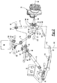
Figure 1 is a perspective view of a suspension system. -
Figure 2 is an exploded view of a portion of the suspension system ofFigure 1 . -
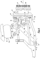
Figure 3 is a front view of the suspension system ofFigure 1 in a first position or nominal position. -
Figure 4 is a front view of the suspension system in a second position. - As required, detailed embodiments of the present invention are disclosed herein; however, it is to be understood that the disclosed embodiments are merely exemplary of the invention that may be embodied in various and alternative forms. The figures are not necessarily to scale; some features may be exaggerated or minimized to show details of particular components. Therefore, specific structural and functional details disclosed herein are not to be interpreted as limiting, but merely as a representative basis for teaching one skilled in the art to variously employ the present invention.
- Referring to
Figure 1 , an example of asuspension system 10 for a vehicle is shown. Thesuspension system 10 may be provided with a motor vehicle like a truck, bus, farm equipment, military transport or weaponry vehicle, or cargo loading equipment for land, air, or marine vessels. - The
suspension system 10 may be an independent suspension system that may allow wheels to move up and down independently with respect to each other or without influence from another wheel on the axle. In at least one embodiment, thesuspension system 10 may include asubframe 20, awheel end assembly 22, asuspension subsystem 24, and atie rod subassembly 26. InFigure 1 , onewheel end assembly 22,suspension subsystem 24, andtie rod subassembly 26 are shown that extend from one lateral side of thesubframe 20; however, it is to be understood that anotherwheel end assembly 22,suspension subsystem 24, andtie rod subassembly 26 may be mounted to the opposite lateral side of thesubframe 20. - The
subframe 20 may facilitate mounting of thesuspension system 10 to the vehicle. For example, thesubframe 20 may be configured to be mounted to a portion of the vehicle, such as a frame orchassis 28. Thesubframe 20 may or may not be a unitary one-piece component that may be cast or molded to form an individual part. - Referring to
Figures 1 and2 , thesubframe 20 may also facilitate mounting of thesuspension subsystem 24. For instance, thesubframe 20 may have one or more upper controlarm mounting holes 30, one or more lower controlarm mounting holes 32, and ashock absorber mount 34. - The upper control
arm mounting holes 30 may be configured to receive a corresponding ends of an upper control arm as will be discussed in more detail below. In addition, one or more upper control arm mounts or mounting brackets may be provided to facilitate coupling of the upper control arm to thesubframe 20. The upper control arm mounts may pivotally connect the upper control arm to thesubframe 20 such that the upper control arm may rotate with respect to thesubframe 20 about afirst axis 40, which is best shown inFigure 3 . It is also contemplated that the upper control arm may be mounted to a side of thesubframe 20 and the upper controlarm mounting holes 30 may be omitted in various configurations. - The lower control
arm mounting holes 32 may be configured to receive a corresponding ends of a lower control arm as will be discussed in more detail below. In addition, one or more lower control arm mounts or mounting brackets may be provided to facilitate coupling of the lower control arm to thesubframe 20. The lower control arm mounts may pivotally connect the lower control arm to thesubframe 20 such that the lower control arm may rotate with respect to the subframe about a lowercontrol arm axis 42, which is best shown inFigure 3 . It is also contemplated that the lower control arm may be mounted to a side of thesubframe 20 and the lower controlarm mounting holes 32 may be omitted in various configurations. - Referring to
Figure 3 , theshock absorber mount 34 may be configured to facilitate mounting of a shock absorber to thesubframe 20. Theshock absorber mount 34 may be disposed between the lower controlarm mounting holes 32. A shock absorber may be pivotally connected to theshock absorber mount 34 in any suitable manner, such as with a mounting pin or bolt that may allow the shock absorber to rotate about a first shockabsorber mounting axis 44. - Referring to
Figures 1 and3 , thewheel end assembly 22 may facilitate rotation and braking of a wheel that may support a tire. For example, thewheel end assembly 22 may include ahub 50 and abrake subsystem 52. - The
hub 50 may be rotatably disposed on a spindle of a steering knuckle as will be discussed in more detail below. Thehub 50 may facilitate mounting of the wheel, such as with a plurality ofmounting studs 54. - The
brake subsystem 52 may facilitate braking of the wheel to slow rotation of thehub 50 and wheel about a wheel axis ofrotation 56. Thebrake subsystem 52 may have any suitable configuration. For instance, thebrake subsystem 52 may be configured as a friction brake, such as a disc brake or a drum brake. - Referring to
Figure 1 , thesuspension subsystem 24 may connect thewheel end assembly 22 to thesubframe 20. Moreover, thesuspension subsystem 24 may allow thewheel end assembly 22 to move up and down or in a generally vertical direction with respect to thesubframe 20. In at least one embodiment, thesuspension subsystem 24 may include anupper control arm 60, alower control arm 62, apiston platform 64, anair spring 66, asteering knuckle 68, akingpin 70, aninner steering knuckle 72, asupport linkage 74, and ashock absorber 76. - The
upper control arm 60 may extend from a lateral side of thesubframe 20. Theupper control arm 60 may be pivotally or rotatably mounted to thesubframe 20 in a manner that allows a correspondingwheel end assembly 22 to move up and down while inhibiting forward and backward movement. As is best shown with reference toFigures 2 and3 , theupper control arm 60 may have one or more mountingarms 80, akingpin attachment feature 82, a pistonplatform attachment feature 84, and a shockabsorber attachment feature 86. - One or more mounting
arms 80 may be provided to facilitate coupling of theupper control arm 60 to thesubframe 20. In the configuration shown, two mountingarms 80 are provided that are spaced apart from each other such that thesupport linkage 74 may extend between the mountingarms 80. Eachmounting arm 80 may be received in a corresponding upper controlarm mounting hole 30 and may be pivotally connected to thesubframe 20 via corresponding upper control arm mounts that may allow theupper control arm 60 to pivot or rotate with respect to thesubframe 20 about thefirst axis 40. - The
kingpin attachment feature 82 may be provided to facilitate coupling of thekingpin 70 to theupper control arm 60. Thekingpin attachment feature 82 may be disposed at a distal end of theupper control arm 60 that may be disposed opposite the mountingarms 80. As is best shown inFigure 3 , thekingpin attachment feature 82 may be configured to permit thekingpin 70 to rotate about asecond axis 90 with respect to theupper control arm 60. Thesecond axis 90 may be disposed substantially parallel to thefirst axis 40. Thekingpin attachment feature 82 may have any suitable configuration. In the embodiment shown, thekingpin attachment feature 82 may have one or more holes that may receive afastener 92, such as a pin or bolt, that may pivotally or rotatably couple thekingpin 70 to thekingpin attachment feature 82. - The piston
platform attachment feature 84 may be provided to facilitate coupling of thepiston platform 64 to theupper control arm 60. The pistonplatform attachment feature 84 may be laterally disposed between the mountingarms 80 and thekingpin attachment feature 82. In addition, the pistonplatform attachment feature 84 may be disposed on or may extend from an upper side of theupper control arm 60 that faces toward thepiston platform 64. As such, the pistonplatform attachment feature 84 may extend away from theshock absorber 76 and toward theair spring 66. As is best shown inFigure 3 , the pistonplatform attachment feature 84 may be configured to permit thepiston platform 64 to rotate about athird axis 94 with respect to theupper control arm 60. Thethird axis 94 may be disposed substantially parallel to thefirst axis 40 and thesecond axis 90. The pistonplatform attachment feature 84 may have any suitable configuration. In the embodiment shown, the pistonplatform attachment feature 84 may have one or more holes that may receive afastener 96, such as a pin or bolt, that may pivotally or rotatably couple thepiston platform 64 to the pistonplatform attachment feature 84. - The shock
absorber attachment feature 86 may be provided to facilitate coupling of theshock absorber 76 to theupper control arm 60. The shockabsorber attachment feature 86 may be laterally disposed between the mountingarms 80 and thekingpin attachment feature 82. In addition, the shockabsorber attachment feature 86 may be disposed on or may extend from a lower side of theupper control arm 60 that faces toward thelower control arm 62. As such, the shockabsorber attachment feature 86 may be disposed opposite or may extend in opposite direction from the pistonplatform attachment feature 84. As is best shown inFigure 3 , the shockabsorber attachment feature 86 may be configured to permit theshock absorber 76 to rotate about a second shockabsorber mounting axis 100 with respect to theupper control arm 60. The second shockabsorber mounting axis 100 may be disposed substantially parallel to thefirst axis 40, thesecond axis 90, and thethird axis 94. The shockabsorber attachment feature 86 may have any suitable configuration. In the embodiment shown, the shockabsorber attachment feature 86 may have one or more holes that may receive afastener 102, such as a pin or bolt, that may pivotally or rotatably couple theshock absorber 76 to theupper control arm 60. - An
upper control arm 60 and alower control arm 62 may extend from each lateral side of thesubframe 20. Oneupper control arm 60 and onelower control arm 62 may be associated with eachwheel end assembly 22. As such, twoupper control arms 60 and twolower control arms 62 may be provided with thesuspension system 10 and may extend from opposite sides of thesubframe 20 to support differentwheel end assemblies 22. - Referring to
Figures 2 and3 , thelower control arm 62 may be disposed below theupper control arm 60. Like theupper control arm 60, thelower control arm 62 may extend from a lateral side of thesubframe 20 and may be pivotally or rotatably mounted to thesubframe 20 in a manner that allows a correspondingwheel end assembly 22 to move up and down while inhibiting forward and backward movement. In at least one embodiment, thelower control arm 62 may have one or more mountingarms 110 and akingpin mounting feature 112. - One or more
mounting arms 110 may be provided to facilitate coupling of thelower control arm 62 to thesubframe 20. In the configuration shown, two mountingarms 110 are provided that are spaced apart from each other such that theshock absorber 76 may be disposed between them. Each mountingarm 110 may be received in a corresponding lower controlarm mounting hole 32 and may be pivotally connected to thesubframe 20 via a lower control arm mount that may allow thelower control arm 62 to pivot or rotate with respect to thesubframe 20 about the lowercontrol arm axis 42. - The
kingpin mounting feature 112 may be provided to facilitate coupling of thekingpin 70 to thelower control arm 62. Thekingpin mounting feature 112 may be disposed near a distal end of thelower control arm 62 and may be located below thesteering knuckle 68. Thekingpin mounting feature 112 may have any suitable configuration. For example, thekingpin mounting feature 112 may be configured as a hole that may receive and may engage an end of thekingpin 70, such as with an interference fit. As such, thekingpin 70 may be fixedly disposed on thelower control arm 62 such that thekingpin 70 does not rotate with respect to thelower control arm 62. - With continued reference to
Figures 2 and3 , thepiston platform 64 may support theair spring 66. Moreover, thepiston platform 64 may be configured to pivot or rotate with respect to theupper control arm 60 when thewheel end assembly 22 moves up or down such that thepiston platform 64 may remain in a generally constant angular orientation (e.g., generally horizontal) to help control and maintain positioning of theair spring 66. As such, thepiston platform 64 may rotate with respect to theupper control arm 60 when theupper control arm 60 rotates up or down with respect to thesubframe 20. In at least one embodiment, thepiston platform 64 may include aplatform 120, an upper controlarm attachment feature 122, and a supportlinkage attachment feature 124. - The
platform 120 may be disposed proximate theair spring 66 and may engage theair spring 66. Theplatform 120 may be configured as a plate that may form an upper surface of theplatform 120. - The upper control
arm attachment feature 122 may be provided to facilitate coupling of thepiston platform 64 to theupper control arm 60. The upper controlarm attachment feature 122 may be disposed under theplatform 120 and may extend away from theair spring 66 and toward theupper control arm 60. In addition, the upper controlarm attachment feature 122 may be laterally disposed further away from thesubframe 20 and closer to thekingpin 70 than the supportlinkage attachment feature 124. The upper controlarm attachment feature 122 may have any suitable configuration. For example, the upper controlarm attachment feature 122 may include one or more holes that may receive thefastener 96. In at least one embodiment, the upper controlarm attachment feature 122 may be received in the pistonplatform attachment feature 84. As such, the pistonplatform attachment feature 84 and the upper controlarm attachment feature 122 may cooperate to permit thepiston platform 64 to rotate about thethird axis 94 with respect to theupper control arm 60. - The support
linkage attachment feature 124 may be provided to facilitate coupling of thepiston platform 64 to thesupport linkage 74. The supportlinkage attachment feature 124 may be spaced apart from the upper controlarm attachment feature 122. In addition, the supportlinkage attachment feature 124 may be disposed under theplatform 120 and may extend away from theair spring 66. The supportlinkage attachment feature 124 may be laterally disposed closer to thesubframe 20 than the upper controlarm attachment feature 122. The supportlinkage attachment feature 124 may have any suitable configuration. For instance, the supportlinkage attachment feature 124 may include one or more holes that may receive afastener 126 that may pivotally or rotatably couple thesupport linkage 74 to thepiston platform 64. The supportlinkage attachment feature 124 may be configured to permit thesupport linkage 74 to rotate about a firstsupport linkage axis 128 with respect to thepiston platform 64. The firstsupport linkage axis 128 may be disposed substantially parallel to thefirst axis 40,second axis 90, and thethird axis 94. The supportlinkage attachment feature 124 may have any suitable configuration. In the embodiment shown, the supportlinkage attachment feature 124 may have one or more holes that may receive thefastener 126 that may pivotally or rotatably couple thesupport linkage 74 to the supportlinkage attachment feature 124. - Referring to
Figure 3 , theair spring 66 may be disposed on thepiston platform 64. For example, theair spring 66 may extend from thepiston platform 64 to a frame orchassis 28 of the vehicle. Theair spring 66 may help dampen vibrations, provide a desired level of ride quality, and control ride height or the distance between thechassis 28 and the road or support surface upon which a tire of the vehicle is disposed. Theair spring 66 may have any suitable configuration. In at least one embodiment, theair spring 66 may include a flexible bellows 130 and apiston 132. - The flexible bellows 130 may generally extend between the
piston platform 64 and thechassis 28. The flexible bellows 130 may at least partially define a chamber within theair spring 66 that may receive pressurized gas from a pressurized gas supply system. Pressurized gas may be provided to the chamber or may be vented from the chamber to adjust the ride height and dampening characteristics of thesuspension system 10. An upper mounting plate may be provided at the top of theflexible bellows 130 to facilitate mounting of theflexible bellows 130 to thechassis 28. - The
piston 132 may be at least partially received in the flexible bellows 130. Thepiston 132 may extend from thepiston platform 64. For example, thepiston 132 may be fixedly disposed on theplatform 120 and may be generally disposed near the center of the flexible bellows 130. - Referring to
Figures 2 and3 , thesteering knuckle 68 may support thewheel end assembly 22 and may facilitate steering of the vehicle. Thesteering knuckle 68 may be generally disposed between theupper control arm 60 and thelower control arm 62 and may be disposed laterally outboard from thesubframe 20. Thesteering knuckle 68 may include aspindle 140, abody 142, a firststeering knuckle arm 144, and a secondsteering knuckle arm 146. - The
spindle 140 may support thewheel end assembly 22 and facilitate mounting and rotation of a vehicle wheel. As is best shown inFigure 3 , thespindle 140 may extend from thebody 142 and may support one or more roller bearing assemblies that may support and facilitate rotation of thehub 50 and an associated vehicle wheel about the axis ofrotation 56. Thespindle 140 may extend along the wheel axis ofrotation 56 and may be located between and extend away from the firststeering knuckle arm 144 and a secondsteering knuckle arm 146. Thespindle 140 may be integrally formed with thebody 142 or may be provided as a separate component that is fastened to thebody 142 in one or more embodiments. - The
body 142 may facilitate mounting of various components to thesteering knuckle 68. For instance, thebody 142 may facilitate mounting of thebrake subsystem 52 such that various components of thebrake subsystem 52, such as a brake caliper and brake pad assemblies, do not rotate about the wheel axis ofrotation 56. - The first
steering knuckle arm 144 may extend from thebody 142. The firststeering knuckle arm 144, which may also be referred to as an upper steering knuckle arm, may generally extend in an opposite direction from thespindle 140 and may be disposed above thespindle 140 near the top of thebody 142. The firststeering knuckle arm 144 may include a firstkingpin mounting hole 150. The firstkingpin mounting hole 150 may be a through hole that may extend through the firststeering knuckle arm 144 and may receive thekingpin 70. - The second
steering knuckle arm 146 may extend from thebody 142 and may be spaced apart from the firststeering knuckle arm 144. The secondsteering knuckle arm 146, which may also be referred to as a lower steering knuckle arm, may extend in an opposite direction from thespindle 140 and may be disposed below thespindle 140 near the bottom of thebody 142. The secondsteering knuckle arm 146 may include a secondkingpin mounting hole 152 and a steeringarm mounting feature 154. - The second
kingpin mounting hole 152 may be a through hole that may extend through the secondsteering knuckle arm 146 and may receive thekingpin 70. The secondkingpin mounting hole 152 may be coaxially disposed with the firstkingpin mounting hole 150. - The steering
arm mounting feature 154 may be disposed proximate a distal end of the secondsteering knuckle arm 146. The steeringarm mounting feature 154 may facilitate coupling of thesteering knuckle 68 to thetie rod subassembly 26. The steeringarm mounting feature 154 may have any suitable configuration, such as a male configuration or a female configuration like a hole as shown inFigure 2 . - Referring to
Figures 2 and3 , thekingpin 70 may interconnect theupper control arm 60,lower control arm 62, steeringknuckle 68, andinner steering knuckle 72. For instance, thekingpin 70 may extend from theupper control arm 60 to thelower control arm 62 and may facilitate mounting of thesteering knuckle 68 and theinner steering knuckle 72. Thekingpin 70 may extend along akingpin axis 160 and may have a first end, a second end, and a kingpin body. - The first end of the
kingpin 70 may be pivotally or rotatably mounted to theupper control arm 60. For instance, the first end of thekingpin 70 may be provided with a mountinghole 162 that may receive thefastener 92. - The second end of the
kingpin 70 may be disposed opposite the first end. The second end of thekingpin 70 may be coupled to thelower control arm 62. For instance, the second end of thekingpin 70 may be received in thekingpin mounting feature 112 of thelower control arm 62. - The body of the
kingpin 70 may extend between the first end and the second end. The body of thekingpin 70 may have a generally cylindrical configuration and may extend through the firstkingpin mounting hole 150 and the secondkingpin mounting hole 152. As such, thesteering knuckle 68 may rotate about the body of thekingpin 70 and thekingpin axis 160. The body of thekingpin 70 may also extend through theinner steering knuckle 72. In addition, thesteering knuckle 68 and theinner steering knuckle 72 may be mounted on thekingpin 70 such that thesteering knuckle 68 and theinner steering knuckle 72 do not slide or move along thekingpin axis 160 with respect to thekingpin 70. - The
inner steering knuckle 72 may interconnect thekingpin 70 and thesupport linkage 74. As is best shown inFigure 2 , theinner steering knuckle 72 may have an innersteering knuckle body 170 and one or more innersteering knuckle arms 172. - The inner
steering knuckle body 170 may be disposed between the firststeering knuckle arm 144 and the secondsteering knuckle arm 146 of thesteering knuckle 68. The innersteering knuckle body 170 may be spaced apart from thebody 142 of thesteering knuckle 68 and may have a hole that may receive thekingpin 70. - One or more inner
steering knuckle arms 172 may extend from the innersteering knuckle body 170. In the embodiment shown inFigure 2 , two innersteering knuckle arms 172 are provided. The innersteering knuckle arms 172 may each have anopening 174 that may receive afastener 176, such as a pin or bolt, that may pivotally or rotatably couple thesupport linkage 74 to theinner steering knuckle 72. - The
support linkage 74 may be provided to transmit load forces between theinner steering knuckle 72 and thepiston platform 64. As such, thesupport linkage 74 may support a majority of the vertical load forces that may be transmitted between thewheel end assembly 22 and theair spring 66. Thesupport linkage 74 may have a fixed or constant length and may have a first end and a second end. - The first end may be pivotally or rotatably coupled to the
piston platform 64 to allow thepiston platform 64 to pivot or rotate about the firstsupport linkage axis 128 with respect to thesupport linkage 74. As such, thesupport linkage 74 may help constrain or limit rotation of thepiston platform 64 about thethird axis 94 and thereby help maintain the angular position of thepiston platform 64 in a substantially constant orientation or within a predetermined angular range of motion. - The second end may be disposed opposite the first end may be pivotally or rotatably coupled to the
inner steering knuckle 72. For instance, the second end may be disposed between the innersteering knuckle arms 172 and may be coupled to the innersteering knuckle arms 172 with thefastener 176 that may allow thesupport linkage 74 to pivot or rotate about a secondsupport linkage axis 180 with respect to theinner steering knuckle 72. - The
shock absorber 76 may be provided to control and dampen movement of thesuspension subsystem 24. More specifically, theshock absorber 76 may exert a biasing force that may bias theupper control arm 60 toward theair spring 66. Theshock absorber 76 may have a first end and a second end. The first end may be pivotally or rotatably coupled to theshock absorber mount 34 of thesubframe 20 and may rotate about the first shockabsorber mounting axis 44. The second end may be disposed opposite the first end and may be pivotally or rotatably coupled to the shock absorber attachment feature 86 of theupper control arm 60 along the second shockabsorber mounting axis 100. The second shockabsorber mounting axis 100 may be disposed above the first shockabsorber mounting axis 44. The first end of theshock absorber 76 may be disposed closer to thesubframe 20 than the second end. - Referring again to
Figure 1 , thetie rod subassembly 26 may include atie rod 190 and asteering arm 192. - The
tie rod 190 may transmit force from a steering system to thesteering knuckle 68 to steer the vehicle. More specifically, force that is transmitted by thetie rod 190 to thesteering knuckle 68 may rotate thesteering knuckle 68 about thekingpin 70 and thekingpin axis 160. Thetie rod 190 may have a first end and a second end. The first end may be coupled to a center link or other suitable component that may be operatively connected to a steering gear or actuator of the steering system. The second end may be disposed opposite the first end and may be coupled to thesteering arm 192. - The
steering arm 192 may transmit force from thetie rod 190 to thesteering knuckle 68. InFigure 2 , thesteering arm 192 is shown as a component that is separate from thesteering knuckle 68; however, it is contemplated that thesteering arm 192 may be integrally formed with thesteering knuckle 68 in one or more embodiments. Thesteering arm 192 may have a generally L-shaped configuration that may have a first end and a second end. The first end may be fastened to thesteering knuckle 68. For example, the first end may be received in and may be fastened to the steeringarm mounting feature 154 of thesteering knuckle 68. The second end may be disposed opposite the first end and may be fastened to thetie rod 190. For instance, the second end may have a tie rod mounting hole that may receive a ball joint or other suitable coupling member that may facilitate coupling of thetie rod 190 to thesteering arm 192. - Referring to
Figures 3 and4 , operation and movement of thesuspension system 10 andsuspension subsystem 24 will now be described in more detail. InFigure 3 , thesuspension system 10 is shown in a first position or nominal position. InFigure 4 , thesuspension system 10 is shown in an exemplary second position or raised position in which thewheel end assembly 22 andsuspension subsystem 24 are pivoted upward with respect to thesubframe 20. - In
Figures 3 and4 , thesubframe 20 and thechassis 28 are shown in substantially constant positions. Changes in the contour of the road or support surface upon which the tire of the vehicle is disposed may cause thesuspension subsystem 24 to move with respect to thesubframe 20. For example, thewheel end assembly 22 may move upward from the position shown inFigure 3 to the position shown inFigure 4 when a tire that is mounted on thewheel end assembly 22 encounters on a protrusion or bump on the support surface. Such a bump may transmit force to thewheel end assembly 22 that biases thewheel end assembly 22 upward. - Upward movement of the
wheel end assembly 22 may actuate or move thekingpin 70 and theinner steering knuckle 72 upward since thesteering knuckle 68,kingpin 70, andinner steering knuckle 72 are inhibited from moving with respect to each other along thekingpin axis 160. - In response to upward movement of the
kingpin 70, theupper control arm 60 may pivot or rotate upward about thefirst axis 40 with respect to thesubframe 20 and thelower control arm 62 may pivot or rotate upward about the lowercontrol arm axis 42 with respect to thesubframe 20. Theupper control arm 60 may also pivot or rotate about thesecond axis 90 with respect to thekingpin 70 and may allow thekingpin 70 to move upward along with thewheel end assembly 22, steeringknuckle 68 andinner steering knuckle 72. - Upward movement of the
upper control arm 60 may actuate or move thepiston platform 64 upward and inward toward thesubframe 20. Upward movement of theinner steering knuckle 72 may transmit force to thepiston platform 64 by way of thesupport linkage 74 and cause thepiston platform 64 to rotate or pivot about thethird axis 94 due to the constant length of thesupport linkage 74. The constant length of thesupport linkage 74 may help maintain or control the range of motion of thepiston platform 64 about thethird axis 94 in a manner that helps hold thepiston platform 64 at a predetermined angle or within a predetermined angular range of motion with respect to thesubframe 20, which may help align theplatform 120 of thepiston platform 64 and thechassis 28. - Upward movement of the
piston platform 64 may actuate or move thepiston platform 64 closer to thechassis 28, which in turn may compress theair spring 66. - The
shock absorber 76 may rotate about the first shockabsorber mounting axis 44 and the second shockabsorber mounting axis 100. In addition, theshock absorber 76 may extend in length as theupper control arm 60 and the second shockabsorber mounting axis 100 rotate and move further away from the first shockabsorber mounting axis 44. - It is noted that the
wheel end assembly 22 and thesuspension subsystem 24 may also pivot downward with respect to thesubframe 20 from the position shown inFigure 3 , in which case theshock absorber 76 may contract or reduce in length and rotation of the suspension subsystem components may be reversed from the scenario described above. - While exemplary embodiments are described above, it is not intended that these embodiments describe all possible forms of the invention. Rather, the words used in the specification are words of description rather than limitation, and it is understood that various changes may be made without departing from the spirit and scope of the invention. Additionally, the features of various implementing embodiments may be combined to form further embodiments of the invention.
Claims (15)
- A suspension system comprising:a subframe;an upper control arm that is pivotally mounted to the subframe;a piston platform that is pivotally mounted to the upper control arm;an air spring that is disposed on the piston platform;a kingpin that is pivotally mounted to the upper control arm; anda steering knuckle that is rotatably mounted to the kingpin.
- The suspension system of claim 1 wherein the piston platform rotates with respect to the upper control arm when the upper control arm rotates with respect to the subframe.
- The suspension system of any preceding claim wherein the piston platform is disposed directly above the upper control arm.
- The suspension system of any preceding claim further comprising a lower control arm that is pivotally mounted to the subframe and that receives the kingpin.
- The suspension system of any preceding claim wherein the kingpin is rotatably mounted at to the upper control arm an end of the upper control arm that is disposed opposite the subframe.
- The suspension system of any preceding claim wherein the steering knuckle has a first steering knuckle arm and a second steering knuckle arm through which the kingpin extends and the suspension system further comprises an inner steering knuckle that receives the kingpin and is disposed between the first steering knuckle arm and the second steering knuckle arm.
- The suspension system of claim 6 further comprising a support linkage that is pivotally mounted to the inner steering knuckle and the piston platform, wherein the support linkage has a constant length.
- The suspension system of claim 7 wherein the support linkage is pivotally mounted to the piston platform above the upper control arm and is disposed between the subframe and a piston platform attachment feature at which the piston platform is pivotally mounted to the upper control arm.
- The suspension system of claim 8 further comprising a shock absorber that is pivotally mounted to the subframe and to the upper control arm, preferably the shock absorber is mounted to the upper control arm under the piston platform attachment feature and/or the shock absorber exerts a biasing force that biases the upper control arm upward toward the air spring.
- The suspension system of claim 1 wherein the upper control arm is pivotally mounted to the subframe along a first axis, the kingpin is pivotally mounted to the upper control arm along a second axis, and the piston platform supports the air spring and is pivotally mounted to the upper control arm such that the piston platform pivots about a third axis with respect to the upper control arm, preferably the piston platform rotates with respect to the upper control arm when the upper control arm rotates with respect to the subframe to help control positioning of the air spring.
- The suspension system of claim 10 further comprising:an inner steering knuckle that receives the kingpin; anda support linkage that is pivotally mounted to the inner steering knuckle and the piston platform.
- The suspension system of claim 11 wherein the support linkage is pivotally mounted to the piston platform along a first support linkage axis and is pivotally mounted to the inner steering knuckle along a second support linkage axis.
- The suspension system of claim 12 wherein the third axis and second support linkage axis are disposed above the second axis.
- The suspension system of claim 11-13 wherein the support linkage extends between mounting arms of the upper control arm.
- The suspension system of claim 12-14 further comprising a shock absorber that is pivotally mounted to the subframe along a first shock absorber mounting axis and is pivotally mounted to the upper control arm along a second shock absorber mounting axis, preferably a lower control arm that is pivotally mounted to the subframe and that has a pair of mounting arms, wherein the shock absorber extends between the mounting arms of the lower control arm, preferably the second shock absorber mounting axis is disposed below the third axis and above the second support linkage axis.
Applications Claiming Priority (1)
| Application Number | Priority Date | Filing Date | Title |
|---|---|---|---|
| US15/437,823 US10093356B2 (en) | 2017-02-21 | 2017-02-21 | Suspension system |
Publications (2)
| Publication Number | Publication Date |
|---|---|
| EP3363662A1 true EP3363662A1 (en) | 2018-08-22 |
| EP3363662B1 EP3363662B1 (en) | 2021-06-02 |
Family
ID=61189307
Family Applications (1)
| Application Number | Title | Priority Date | Filing Date |
|---|---|---|---|
| EP18156009.5A Active EP3363662B1 (en) | 2017-02-21 | 2018-02-09 | Suspension system |
Country Status (3)
| Country | Link |
|---|---|
| US (1) | US10093356B2 (en) |
| EP (1) | EP3363662B1 (en) |
| CN (1) | CN108454338B (en) |
Cited By (1)
| Publication number | Priority date | Publication date | Assignee | Title |
|---|---|---|---|---|
| US12291076B2 (en) * | 2023-05-12 | 2025-05-06 | Hyundai Motor Company | Vehicle body structure capable of modular assembly |
Families Citing this family (14)
| Publication number | Priority date | Publication date | Assignee | Title |
|---|---|---|---|---|
| CN107532661B (en) * | 2015-02-24 | 2019-05-07 | 赛迈道依茨-法尔意大利股份公司 | Wheel carrier assembly with disc brakes |
| DE102015211529B4 (en) * | 2015-06-23 | 2025-10-30 | Zf Friedrichshafen Ag | Independent suspension |
| US11001129B2 (en) | 2015-12-30 | 2021-05-11 | Nikola Corporation | Cargo door for semi-truck |
| US10981609B2 (en) | 2015-12-30 | 2021-04-20 | Nikola Corporation | Systems, methods, and devices for an automobile door or window |
| US10207751B2 (en) | 2016-05-09 | 2019-02-19 | Nikola Motor Company Llc | Motor gearbox assembly |
| US10435075B2 (en) | 2016-05-06 | 2019-10-08 | Arvinmeritor Technology, Llc | Suspension module having a subframe assembly |
| DE102019202185A1 (en) * | 2019-02-19 | 2020-08-20 | Zf Friedrichshafen Ag | Wheel suspension for a commercial vehicle |
| US10926596B2 (en) | 2019-02-28 | 2021-02-23 | Arvinmeritor Technology, Llc | Suspension system |
| US10814917B2 (en) * | 2019-03-04 | 2020-10-27 | Arvinmeritor Technology, Llc | Assembly having a skid plate module |
| US10913321B2 (en) | 2019-03-04 | 2021-02-09 | Arvinmeritor Technology, Llc | Suspension system |
| JP7419924B2 (en) * | 2020-03-27 | 2024-01-23 | マツダ株式会社 | Vehicle suspension equipment |
| KR102581663B1 (en) * | 2021-09-06 | 2023-09-21 | 김광석 | Detachable Subsidiary Device for Rear Wheel Absorber |
| CN115583128B (en) * | 2022-08-18 | 2025-05-09 | 台州市驰安汽车零部件有限公司 | A car suspension |
| CN116639188A (en) * | 2023-06-28 | 2023-08-25 | 中国第一汽车股份有限公司 | Automobile chassis and automobile with same |
Citations (6)
| Publication number | Priority date | Publication date | Assignee | Title |
|---|---|---|---|---|
| US3193304A (en) * | 1963-12-23 | 1965-07-06 | Ford Motor Co | Vehicle suspension system having an articulated spring support |
| FR1533988A (en) * | 1967-06-13 | 1968-07-26 | Simca Automobiles Sa | Suspension device, in particular for a motor vehicle |
| US20040150142A1 (en) | 2003-02-05 | 2004-08-05 | Warinner Derek K. | Steering beam axle air spring suspension |
| DE102007047789A1 (en) * | 2007-11-15 | 2009-05-20 | Zf Friedrichshafen Ag | Individual wheel suspension for vehicle, has steering knuckle, which is pivotally disposed around pivot axis, and steering knuckle is supported on spring support connected to vehicle chassis by shock absorber |
| EP2631094A2 (en) * | 2012-02-23 | 2013-08-28 | ArvinMeritor Technology, LLC | Suspension module for a vehicle and a method of manufacture |
| WO2017008952A2 (en) * | 2015-07-10 | 2017-01-19 | Bayerische Motoren Werke Aktiengesellschaft | Double-wishbone axle |
Family Cites Families (23)
| Publication number | Priority date | Publication date | Assignee | Title |
|---|---|---|---|---|
| US3477738A (en) * | 1968-01-16 | 1969-11-11 | Gen Motors Corp | Auxiliary road wheel assembly |
| JPH01145214A (en) | 1987-12-01 | 1989-06-07 | Honda Motor Co Ltd | Horizontally placed leaf spring type suspension |
| SE508519C2 (en) | 1994-06-28 | 1998-10-12 | Volvo Ab | Wheel suspension for a pair of driven vehicle wheels |
| NL1000342C2 (en) | 1995-05-11 | 1996-11-12 | Weweler Nv | Air suspension system. |
| DE19646081A1 (en) * | 1996-11-08 | 1998-05-14 | Zahnradfabrik Friedrichshafen | Independent suspension |
| CA2313108A1 (en) * | 1997-12-12 | 1999-06-24 | Neway Anchorlok International, Inc | Independent front suspension |
| WO2001051300A1 (en) | 2000-01-11 | 2001-07-19 | Bridgestone/Firestone, Inc. | Pneumatic suspension system for vehicles |
| US6840525B1 (en) | 2000-03-14 | 2005-01-11 | Meritor Heavy Vehicle Systems Limited | Air spring and pedestal |
| SE525912C2 (en) | 2000-05-18 | 2005-05-24 | Volvo Personvagnar Ab | Wheel suspension for a vehicle |
| US6398262B1 (en) * | 2000-09-26 | 2002-06-04 | Dana Corporation | Modular subframe assembly for a motor vehicle |
| US6783137B2 (en) * | 2002-11-14 | 2004-08-31 | Tuthill Corporation | Steering knuckle carrier-to-suspension arm pivotal connection and method of assembling and preloading the pivotal connection |
| US7798506B2 (en) * | 2003-10-03 | 2010-09-21 | Gpv, L.L.C. | Wheel suspension system for vehicles |
| CN2776727Y (en) * | 2004-10-25 | 2006-05-03 | 上海科曼车辆部件系统有限公司 | Full air front suspension structure of automobile |
| US7819411B2 (en) | 2005-05-20 | 2010-10-26 | Arvinmeritor Technology, Llc | Six link independent suspension for a drive axle |
| WO2008115293A2 (en) * | 2006-11-28 | 2008-09-25 | Arvinmeritor Technology, Llc | High travel independent suspension with upright |
| US8485543B2 (en) | 2009-04-29 | 2013-07-16 | Reyco Granning, Llc | Independent suspension and steering assembly |
| US8925941B2 (en) * | 2011-10-13 | 2015-01-06 | Axletech International Ip Holdings, Llc | Modular independent suspension and method of producing the same |
| US8967639B2 (en) * | 2013-01-28 | 2015-03-03 | Saf-Holland, Inc. | Auxiliary axle and suspension assembly |
| CN203511207U (en) * | 2013-08-15 | 2014-04-02 | 上海通用汽车有限公司 | Double wishbone suspension and vehicle body equipment with double wishbone suspension |
| CN203543564U (en) * | 2013-09-09 | 2014-04-16 | 上海通用汽车有限公司 | Vehicular double-wishbone suspension structure and vehicle |
| US9387881B2 (en) * | 2013-11-18 | 2016-07-12 | Terra Drive Systems, Inc. | Land vehicle steering system including selective inboard and outboard wheels adjustment |
| US9022402B1 (en) * | 2014-02-04 | 2015-05-05 | Atieva, Inc. | Compact rear suspension damper-spring assembly |
| JP6313610B2 (en) * | 2014-02-27 | 2018-04-18 | Ntn株式会社 | CONNECTION STRUCTURE OF IN-WHEEL MOTOR DRIVE DEVICE AND DAMPER AND SUSPENSION DEVICE PROVIDED WITH THIS CONNECTION |
-
2017
- 2017-02-21 US US15/437,823 patent/US10093356B2/en active Active
-
2018
- 2018-02-09 EP EP18156009.5A patent/EP3363662B1/en active Active
- 2018-02-13 CN CN201810149040.0A patent/CN108454338B/en not_active Expired - Fee Related
Patent Citations (6)
| Publication number | Priority date | Publication date | Assignee | Title |
|---|---|---|---|---|
| US3193304A (en) * | 1963-12-23 | 1965-07-06 | Ford Motor Co | Vehicle suspension system having an articulated spring support |
| FR1533988A (en) * | 1967-06-13 | 1968-07-26 | Simca Automobiles Sa | Suspension device, in particular for a motor vehicle |
| US20040150142A1 (en) | 2003-02-05 | 2004-08-05 | Warinner Derek K. | Steering beam axle air spring suspension |
| DE102007047789A1 (en) * | 2007-11-15 | 2009-05-20 | Zf Friedrichshafen Ag | Individual wheel suspension for vehicle, has steering knuckle, which is pivotally disposed around pivot axis, and steering knuckle is supported on spring support connected to vehicle chassis by shock absorber |
| EP2631094A2 (en) * | 2012-02-23 | 2013-08-28 | ArvinMeritor Technology, LLC | Suspension module for a vehicle and a method of manufacture |
| WO2017008952A2 (en) * | 2015-07-10 | 2017-01-19 | Bayerische Motoren Werke Aktiengesellschaft | Double-wishbone axle |
Cited By (1)
| Publication number | Priority date | Publication date | Assignee | Title |
|---|---|---|---|---|
| US12291076B2 (en) * | 2023-05-12 | 2025-05-06 | Hyundai Motor Company | Vehicle body structure capable of modular assembly |
Also Published As
| Publication number | Publication date |
|---|---|
| US10093356B2 (en) | 2018-10-09 |
| CN108454338A (en) | 2018-08-28 |
| EP3363662B1 (en) | 2021-06-02 |
| US20180237070A1 (en) | 2018-08-23 |
| CN108454338B (en) | 2021-09-14 |
Similar Documents
| Publication | Publication Date | Title |
|---|---|---|
| EP3363662B1 (en) | Suspension system | |
| JP6979501B2 (en) | Vehicle suspension | |
| EP3241692B1 (en) | Suspension module having an air spring pedestal | |
| EP3705321B1 (en) | Suspension system | |
| US8267416B2 (en) | Independent rear suspension | |
| US10814917B2 (en) | Assembly having a skid plate module | |
| US20170320522A1 (en) | Suspension Module Having a Subframe Assembly | |
| EP2969604B1 (en) | Vehicle suspension system | |
| CA2754287A1 (en) | Vehicle suspension | |
| US11207934B2 (en) | Vehicle suspension assembly | |
| US20050006868A1 (en) | Control rod suspension with outboard shock | |
| US2994396A (en) | Suspension and steering assembly | |
| GB2582330A (en) | Steering axle assembly | |
| US7618049B2 (en) | Trailing arm suspension | |
| CN105365510A (en) | Vehicle suspension | |
| US10639954B2 (en) | Multi-link suspension system | |
| SE529758C2 (en) | Individual wheel suspension | |
| KR20070035874A (en) | McPherson strut suspension for wheel camber control | |
| HK1234707A1 (en) | Vehicle suspension | |
| HK1234707B (en) | Vehicle suspension |
Legal Events
| Date | Code | Title | Description |
|---|---|---|---|
| PUAI | Public reference made under article 153(3) epc to a published international application that has entered the european phase |
Free format text: ORIGINAL CODE: 0009012 |
|
| STAA | Information on the status of an ep patent application or granted ep patent |
Free format text: STATUS: THE APPLICATION HAS BEEN PUBLISHED |
|
| AK | Designated contracting states |
Kind code of ref document: A1 Designated state(s): AL AT BE BG CH CY CZ DE DK EE ES FI FR GB GR HR HU IE IS IT LI LT LU LV MC MK MT NL NO PL PT RO RS SE SI SK SM TR |
|
| AX | Request for extension of the european patent |
Extension state: BA ME |
|
| STAA | Information on the status of an ep patent application or granted ep patent |
Free format text: STATUS: REQUEST FOR EXAMINATION WAS MADE |
|
| 17P | Request for examination filed |
Effective date: 20190221 |
|
| RBV | Designated contracting states (corrected) |
Designated state(s): AL AT BE BG CH CY CZ DE DK EE ES FI FR GB GR HR HU IE IS IT LI LT LU LV MC MK MT NL NO PL PT RO RS SE SI SK SM TR |
|
| RIC1 | Information provided on ipc code assigned before grant |
Ipc: B60G 3/20 20060101AFI20200130BHEP Ipc: B60G 7/00 20060101ALI20200130BHEP |
|
| STAA | Information on the status of an ep patent application or granted ep patent |
Free format text: STATUS: EXAMINATION IS IN PROGRESS |
|
| 17Q | First examination report despatched |
Effective date: 20200331 |
|
| GRAP | Despatch of communication of intention to grant a patent |
Free format text: ORIGINAL CODE: EPIDOSNIGR1 |
|
| STAA | Information on the status of an ep patent application or granted ep patent |
Free format text: STATUS: GRANT OF PATENT IS INTENDED |
|
| INTG | Intention to grant announced |
Effective date: 20210120 |
|
| RIN1 | Information on inventor provided before grant (corrected) |
Inventor name: SADLIK, ADAM Inventor name: LORENZ, EDWIN Inventor name: WEEKS, GORDON |
|
| GRAS | Grant fee paid |
Free format text: ORIGINAL CODE: EPIDOSNIGR3 |
|
| GRAA | (expected) grant |
Free format text: ORIGINAL CODE: 0009210 |
|
| STAA | Information on the status of an ep patent application or granted ep patent |
Free format text: STATUS: THE PATENT HAS BEEN GRANTED |
|
| REG | Reference to a national code |
Ref country code: CH Ref legal event code: EP |
|
| AK | Designated contracting states |
Kind code of ref document: B1 Designated state(s): AL AT BE BG CH CY CZ DE DK EE ES FI FR GB GR HR HU IE IS IT LI LT LU LV MC MK MT NL NO PL PT RO RS SE SI SK SM TR |
|
| REG | Reference to a national code |
Ref country code: GB Ref legal event code: FG4D |
|
| REG | Reference to a national code |
Ref country code: AT Ref legal event code: REF Ref document number: 1398102 Country of ref document: AT Kind code of ref document: T Effective date: 20210615 |
|
| REG | Reference to a national code |
Ref country code: IE Ref legal event code: FG4D |
|
| REG | Reference to a national code |
Ref country code: DE Ref legal event code: R096 Ref document number: 602018017862 Country of ref document: DE |
|
| REG | Reference to a national code |
Ref country code: SE Ref legal event code: TRGR |
|
| REG | Reference to a national code |
Ref country code: LT Ref legal event code: MG9D |
|
| PG25 | Lapsed in a contracting state [announced via postgrant information from national office to epo] |
Ref country code: HR Free format text: LAPSE BECAUSE OF FAILURE TO SUBMIT A TRANSLATION OF THE DESCRIPTION OR TO PAY THE FEE WITHIN THE PRESCRIBED TIME-LIMIT Effective date: 20210602 Ref country code: BG Free format text: LAPSE BECAUSE OF FAILURE TO SUBMIT A TRANSLATION OF THE DESCRIPTION OR TO PAY THE FEE WITHIN THE PRESCRIBED TIME-LIMIT Effective date: 20210902 Ref country code: FI Free format text: LAPSE BECAUSE OF FAILURE TO SUBMIT A TRANSLATION OF THE DESCRIPTION OR TO PAY THE FEE WITHIN THE PRESCRIBED TIME-LIMIT Effective date: 20210602 Ref country code: LT Free format text: LAPSE BECAUSE OF FAILURE TO SUBMIT A TRANSLATION OF THE DESCRIPTION OR TO PAY THE FEE WITHIN THE PRESCRIBED TIME-LIMIT Effective date: 20210602 |
|
| REG | Reference to a national code |
Ref country code: NL Ref legal event code: MP Effective date: 20210602 |
|
| REG | Reference to a national code |
Ref country code: AT Ref legal event code: MK05 Ref document number: 1398102 Country of ref document: AT Kind code of ref document: T Effective date: 20210602 |
|
| PG25 | Lapsed in a contracting state [announced via postgrant information from national office to epo] |
Ref country code: GR Free format text: LAPSE BECAUSE OF FAILURE TO SUBMIT A TRANSLATION OF THE DESCRIPTION OR TO PAY THE FEE WITHIN THE PRESCRIBED TIME-LIMIT Effective date: 20210903 Ref country code: PL Free format text: LAPSE BECAUSE OF FAILURE TO SUBMIT A TRANSLATION OF THE DESCRIPTION OR TO PAY THE FEE WITHIN THE PRESCRIBED TIME-LIMIT Effective date: 20210602 Ref country code: LV Free format text: LAPSE BECAUSE OF FAILURE TO SUBMIT A TRANSLATION OF THE DESCRIPTION OR TO PAY THE FEE WITHIN THE PRESCRIBED TIME-LIMIT Effective date: 20210602 Ref country code: NO Free format text: LAPSE BECAUSE OF FAILURE TO SUBMIT A TRANSLATION OF THE DESCRIPTION OR TO PAY THE FEE WITHIN THE PRESCRIBED TIME-LIMIT Effective date: 20210902 Ref country code: RS Free format text: LAPSE BECAUSE OF FAILURE TO SUBMIT A TRANSLATION OF THE DESCRIPTION OR TO PAY THE FEE WITHIN THE PRESCRIBED TIME-LIMIT Effective date: 20210602 |
|
| PG25 | Lapsed in a contracting state [announced via postgrant information from national office to epo] |
Ref country code: CZ Free format text: LAPSE BECAUSE OF FAILURE TO SUBMIT A TRANSLATION OF THE DESCRIPTION OR TO PAY THE FEE WITHIN THE PRESCRIBED TIME-LIMIT Effective date: 20210602 Ref country code: AT Free format text: LAPSE BECAUSE OF FAILURE TO SUBMIT A TRANSLATION OF THE DESCRIPTION OR TO PAY THE FEE WITHIN THE PRESCRIBED TIME-LIMIT Effective date: 20210602 Ref country code: RO Free format text: LAPSE BECAUSE OF FAILURE TO SUBMIT A TRANSLATION OF THE DESCRIPTION OR TO PAY THE FEE WITHIN THE PRESCRIBED TIME-LIMIT Effective date: 20210602 Ref country code: NL Free format text: LAPSE BECAUSE OF FAILURE TO SUBMIT A TRANSLATION OF THE DESCRIPTION OR TO PAY THE FEE WITHIN THE PRESCRIBED TIME-LIMIT Effective date: 20210602 Ref country code: PT Free format text: LAPSE BECAUSE OF FAILURE TO SUBMIT A TRANSLATION OF THE DESCRIPTION OR TO PAY THE FEE WITHIN THE PRESCRIBED TIME-LIMIT Effective date: 20211004 Ref country code: SM Free format text: LAPSE BECAUSE OF FAILURE TO SUBMIT A TRANSLATION OF THE DESCRIPTION OR TO PAY THE FEE WITHIN THE PRESCRIBED TIME-LIMIT Effective date: 20210602 Ref country code: SK Free format text: LAPSE BECAUSE OF FAILURE TO SUBMIT A TRANSLATION OF THE DESCRIPTION OR TO PAY THE FEE WITHIN THE PRESCRIBED TIME-LIMIT Effective date: 20210602 Ref country code: EE Free format text: LAPSE BECAUSE OF FAILURE TO SUBMIT A TRANSLATION OF THE DESCRIPTION OR TO PAY THE FEE WITHIN THE PRESCRIBED TIME-LIMIT Effective date: 20210602 Ref country code: ES Free format text: LAPSE BECAUSE OF FAILURE TO SUBMIT A TRANSLATION OF THE DESCRIPTION OR TO PAY THE FEE WITHIN THE PRESCRIBED TIME-LIMIT Effective date: 20210602 |
|
| REG | Reference to a national code |
Ref country code: DE Ref legal event code: R097 Ref document number: 602018017862 Country of ref document: DE |
|
| PLBE | No opposition filed within time limit |
Free format text: ORIGINAL CODE: 0009261 |
|
| STAA | Information on the status of an ep patent application or granted ep patent |
Free format text: STATUS: NO OPPOSITION FILED WITHIN TIME LIMIT |
|
| PG25 | Lapsed in a contracting state [announced via postgrant information from national office to epo] |
Ref country code: DK Free format text: LAPSE BECAUSE OF FAILURE TO SUBMIT A TRANSLATION OF THE DESCRIPTION OR TO PAY THE FEE WITHIN THE PRESCRIBED TIME-LIMIT Effective date: 20210602 |
|
| 26N | No opposition filed |
Effective date: 20220303 |
|
| PG25 | Lapsed in a contracting state [announced via postgrant information from national office to epo] |
Ref country code: AL Free format text: LAPSE BECAUSE OF FAILURE TO SUBMIT A TRANSLATION OF THE DESCRIPTION OR TO PAY THE FEE WITHIN THE PRESCRIBED TIME-LIMIT Effective date: 20210602 |
|
| PG25 | Lapsed in a contracting state [announced via postgrant information from national office to epo] |
Ref country code: IT Free format text: LAPSE BECAUSE OF FAILURE TO SUBMIT A TRANSLATION OF THE DESCRIPTION OR TO PAY THE FEE WITHIN THE PRESCRIBED TIME-LIMIT Effective date: 20210602 |
|
| PG25 | Lapsed in a contracting state [announced via postgrant information from national office to epo] |
Ref country code: MC Free format text: LAPSE BECAUSE OF FAILURE TO SUBMIT A TRANSLATION OF THE DESCRIPTION OR TO PAY THE FEE WITHIN THE PRESCRIBED TIME-LIMIT Effective date: 20210602 |
|
| REG | Reference to a national code |
Ref country code: CH Ref legal event code: PL |
|
| REG | Reference to a national code |
Ref country code: BE Ref legal event code: MM Effective date: 20220228 |
|
| PG25 | Lapsed in a contracting state [announced via postgrant information from national office to epo] |
Ref country code: LU Free format text: LAPSE BECAUSE OF NON-PAYMENT OF DUE FEES Effective date: 20220209 |
|
| PG25 | Lapsed in a contracting state [announced via postgrant information from national office to epo] |
Ref country code: LI Free format text: LAPSE BECAUSE OF NON-PAYMENT OF DUE FEES Effective date: 20220228 Ref country code: IE Free format text: LAPSE BECAUSE OF NON-PAYMENT OF DUE FEES Effective date: 20220209 Ref country code: CH Free format text: LAPSE BECAUSE OF NON-PAYMENT OF DUE FEES Effective date: 20220228 |
|
| PG25 | Lapsed in a contracting state [announced via postgrant information from national office to epo] |
Ref country code: BE Free format text: LAPSE BECAUSE OF NON-PAYMENT OF DUE FEES Effective date: 20220228 |
|
| P01 | Opt-out of the competence of the unified patent court (upc) registered |
Effective date: 20230531 |
|
| PG25 | Lapsed in a contracting state [announced via postgrant information from national office to epo] |
Ref country code: HU Free format text: LAPSE BECAUSE OF FAILURE TO SUBMIT A TRANSLATION OF THE DESCRIPTION OR TO PAY THE FEE WITHIN THE PRESCRIBED TIME-LIMIT; INVALID AB INITIO Effective date: 20180209 |
|
| PG25 | Lapsed in a contracting state [announced via postgrant information from national office to epo] |
Ref country code: MK Free format text: LAPSE BECAUSE OF FAILURE TO SUBMIT A TRANSLATION OF THE DESCRIPTION OR TO PAY THE FEE WITHIN THE PRESCRIBED TIME-LIMIT Effective date: 20210602 Ref country code: CY Free format text: LAPSE BECAUSE OF FAILURE TO SUBMIT A TRANSLATION OF THE DESCRIPTION OR TO PAY THE FEE WITHIN THE PRESCRIBED TIME-LIMIT Effective date: 20210602 |
|
| PGFP | Annual fee paid to national office [announced via postgrant information from national office to epo] |
Ref country code: DE Payment date: 20240228 Year of fee payment: 7 Ref country code: GB Payment date: 20240227 Year of fee payment: 7 |
|
| PGFP | Annual fee paid to national office [announced via postgrant information from national office to epo] |
Ref country code: SE Payment date: 20240307 Year of fee payment: 7 Ref country code: FR Payment date: 20240226 Year of fee payment: 7 |
|
| PG25 | Lapsed in a contracting state [announced via postgrant information from national office to epo] |
Ref country code: TR Free format text: LAPSE BECAUSE OF FAILURE TO SUBMIT A TRANSLATION OF THE DESCRIPTION OR TO PAY THE FEE WITHIN THE PRESCRIBED TIME-LIMIT Effective date: 20210602 |
|
| PG25 | Lapsed in a contracting state [announced via postgrant information from national office to epo] |
Ref country code: MT Free format text: LAPSE BECAUSE OF FAILURE TO SUBMIT A TRANSLATION OF THE DESCRIPTION OR TO PAY THE FEE WITHIN THE PRESCRIBED TIME-LIMIT Effective date: 20210602 |
|
| REG | Reference to a national code |
Ref country code: DE Ref legal event code: R119 Ref document number: 602018017862 Country of ref document: DE |
|
| REG | Reference to a national code |
Ref country code: SE Ref legal event code: EUG |
|
| GBPC | Gb: european patent ceased through non-payment of renewal fee |
Effective date: 20250209 |
|
| PG25 | Lapsed in a contracting state [announced via postgrant information from national office to epo] |
Ref country code: DE Free format text: LAPSE BECAUSE OF NON-PAYMENT OF DUE FEES Effective date: 20250902 |
|
| PG25 | Lapsed in a contracting state [announced via postgrant information from national office to epo] |
Ref country code: GB Free format text: LAPSE BECAUSE OF NON-PAYMENT OF DUE FEES Effective date: 20250209 |
|
| PG25 | Lapsed in a contracting state [announced via postgrant information from national office to epo] |
Ref country code: FR Free format text: LAPSE BECAUSE OF NON-PAYMENT OF DUE FEES Effective date: 20250228 |