EP3362195B1 - Flexible lance drive apparatus with autostroke function - Google Patents
Flexible lance drive apparatus with autostroke function Download PDFInfo
- Publication number
- EP3362195B1 EP3362195B1 EP16855927.6A EP16855927A EP3362195B1 EP 3362195 B1 EP3362195 B1 EP 3362195B1 EP 16855927 A EP16855927 A EP 16855927A EP 3362195 B1 EP3362195 B1 EP 3362195B1
- Authority
- EP
- European Patent Office
- Prior art keywords
- drive motor
- pressure
- pneumatic
- reverse
- lance
- Prior art date
- Legal status (The legal status is an assumption and is not a legal conclusion. Google has not performed a legal analysis and makes no representation as to the accuracy of the status listed.)
- Active
Links
Images
Classifications
-
- F—MECHANICAL ENGINEERING; LIGHTING; HEATING; WEAPONS; BLASTING
- F28—HEAT EXCHANGE IN GENERAL
- F28G—CLEANING OF INTERNAL OR EXTERNAL SURFACES OF HEAT-EXCHANGE OR HEAT-TRANSFER CONDUITS, e.g. WATER TUBES OR BOILERS
- F28G1/00—Non-rotary, e.g. reciprocated, appliances
- F28G1/04—Non-rotary, e.g. reciprocated, appliances having articulated tools, e.g. assembled in chain manner
-
- B—PERFORMING OPERATIONS; TRANSPORTING
- B08—CLEANING
- B08B—CLEANING IN GENERAL; PREVENTION OF FOULING IN GENERAL
- B08B9/00—Cleaning hollow articles by methods or apparatus specially adapted thereto
- B08B9/02—Cleaning pipes or tubes or systems of pipes or tubes
- B08B9/027—Cleaning the internal surfaces; Removal of blockages
-
- B—PERFORMING OPERATIONS; TRANSPORTING
- B08—CLEANING
- B08B—CLEANING IN GENERAL; PREVENTION OF FOULING IN GENERAL
- B08B9/00—Cleaning hollow articles by methods or apparatus specially adapted thereto
- B08B9/02—Cleaning pipes or tubes or systems of pipes or tubes
- B08B9/027—Cleaning the internal surfaces; Removal of blockages
- B08B9/04—Cleaning the internal surfaces; Removal of blockages using cleaning devices introduced into and moved along the pipes
- B08B9/043—Cleaning the internal surfaces; Removal of blockages using cleaning devices introduced into and moved along the pipes moved by externally powered mechanical linkage, e.g. pushed or drawn through the pipes
-
- B—PERFORMING OPERATIONS; TRANSPORTING
- B08—CLEANING
- B08B—CLEANING IN GENERAL; PREVENTION OF FOULING IN GENERAL
- B08B5/00—Cleaning by methods involving the use of air flow or gas flow
- B08B5/02—Cleaning by the force of jets, e.g. blowing-out cavities
-
- F—MECHANICAL ENGINEERING; LIGHTING; HEATING; WEAPONS; BLASTING
- F04—POSITIVE - DISPLACEMENT MACHINES FOR LIQUIDS; PUMPS FOR LIQUIDS OR ELASTIC FLUIDS
- F04D—NON-POSITIVE-DISPLACEMENT PUMPS
- F04D25/00—Pumping installations or systems
- F04D25/02—Units comprising pumps and their driving means
- F04D25/06—Units comprising pumps and their driving means the pump being electrically driven
-
- F—MECHANICAL ENGINEERING; LIGHTING; HEATING; WEAPONS; BLASTING
- F04—POSITIVE - DISPLACEMENT MACHINES FOR LIQUIDS; PUMPS FOR LIQUIDS OR ELASTIC FLUIDS
- F04D—NON-POSITIVE-DISPLACEMENT PUMPS
- F04D29/00—Details, component parts, or accessories
- F04D29/002—Details, component parts, or accessories especially adapted for elastic fluid pumps
-
- F—MECHANICAL ENGINEERING; LIGHTING; HEATING; WEAPONS; BLASTING
- F28—HEAT EXCHANGE IN GENERAL
- F28G—CLEANING OF INTERNAL OR EXTERNAL SURFACES OF HEAT-EXCHANGE OR HEAT-TRANSFER CONDUITS, e.g. WATER TUBES OR BOILERS
- F28G15/00—Details
- F28G15/003—Control arrangements
-
- F—MECHANICAL ENGINEERING; LIGHTING; HEATING; WEAPONS; BLASTING
- F28—HEAT EXCHANGE IN GENERAL
- F28G—CLEANING OF INTERNAL OR EXTERNAL SURFACES OF HEAT-EXCHANGE OR HEAT-TRANSFER CONDUITS, e.g. WATER TUBES OR BOILERS
- F28G15/00—Details
- F28G15/04—Feeding and driving arrangements, e.g. power operation
-
- F—MECHANICAL ENGINEERING; LIGHTING; HEATING; WEAPONS; BLASTING
- F28—HEAT EXCHANGE IN GENERAL
- F28G—CLEANING OF INTERNAL OR EXTERNAL SURFACES OF HEAT-EXCHANGE OR HEAT-TRANSFER CONDUITS, e.g. WATER TUBES OR BOILERS
- F28G3/00—Rotary appliances
- F28G3/16—Rotary appliances using jets of fluid for removing debris
- F28G3/163—Rotary appliances using jets of fluid for removing debris from internal surfaces of heat exchange conduits
Definitions
- the present disclosure is directed to high pressure fluid rotary nozzle handling systems.
- embodiments of the present disclosure are directed to an apparatus for advancing and retracting one or more flexible tube cleaning lances from tubes arranged in an array, such as in a heat exchanger, from a position adjacent a heat exchanger tube sheet, and automatically repetitively reversing forward lance feed movement upon encountering an obstruction within a tube or other piping system being cleaned.
- One conventional tube lancing apparatus consists of a rotating reel flexible lance hose take-up and hose dispensing apparatus that carries a predetermined length of flexible lance hose wrapped around a drum.
- the reel in the drum is rotated by an air motor to push the flexible lance out of the drum and into one or two heat exchanger tubes.
- the air motor drive can be automatically reversed upon pneumatically sensing a large air pressure increase in air pressure supplied to the forward directional side motor that occurs if the flexible lance being pushed by the reel rotation encounters an obstruction within a tube being cleaned.
- an air operated valve to the air motor drive shuts off air to the forward side of the air motor and supplies air to the opposite side of the air motor, the air motor reverses, withdrawing the lance for a predetermined time/distance.
- This automatic reversal of the air motor drive can then be repeated until the obstruction within the tube is removed.
- the flexible lance "pecks" at a restriction, or obstruction, within the tube until the undesirable pressure increase is no longer sensed (indicating that the obstruction has been removed).
- This drum and reel apparatus necessarily must be somewhat remotely located from the heat exchanger tube sheet in order to accommodate the size of the drum and air drive motor apparatus.
- US 3,903,912 A discloses a tube cleaning system where a pair of long, straight, small diameter, thin wall lances extend in parallel from a common cleaning fluid manifold to a pair of spray discharge heads.
- the lances are automatically moved into, through, and out of a pair of heat exchanger tubes by a lance drive system.
- the lance drive system comprises structure for moving the lances through the tubes for simultaneously applying straightening forces thereto, apparatus for controlling both the extent of movement of the lances and the flow of cleaning fluid through the lances, and circuitry for automatically reversing and re-reversing the direction of movement of the lances upon engagement of either lance with an obstruction in its respective tube.
- the lance drive system is mounted on a frame which includes structure for aligning the lances with a pair of heat exchanger tubes prior to each operating cycle of the tube cleaning system.
- US 2014/109936 A1 discloses a system and method for cleaning elongated tubes.
- An apparatus for cleaning elongated tubes includes a cart, a lance, a pressure sensing device and a propulsion device.
- the lance sprays material into elongated tubes to clean the elongated tubes.
- the cart supports the lance while the cart is moves in a rail in a forward direction and in a reverse direction.
- the pressure sensing device is located in the cart detects a pressure exerted on the cart as the cart moves in a forward direction in the rail.
- the propulsion device upon the pressure sensing device detecting a pressure crossing a threshold value, propels the cart in the reverse direction for predetermined distance or time before again propelling the first cart in the forward direction.
- a flexible lance drive apparatus in accordance with the present disclosure includes a generally rectangular housing having an array of upper and lower drive rollers in an outer section each rotatably supported by an axle shaft passing laterally through spaced outer and inner walls defining a mid section of the housing.
- a pneumatic drive motor is housed within the mid section of the housing and is connected to each of the upper and lower drive rollers.
- Each lower drive roller shaft is rotatably supported in a fixed position and the upper rollers may be lowered against the lower rollers via a pneumatic cylinder to sandwich a flexible lance therebetween.
- This drive apparatus may be positioned adjacent an entrance into a piping system to be cleaned, such as mounted on a frame fastened to a tube sheet of a heat exchanger tube bundle.
- a control console is connected to the drive motor and to the pneumatic cylinder in the drive apparatus via forward and reverse pneumatic pressure supply I ines such that an operator can stand at the control console remotely from the drive apparatus so as to avoid the high pressure water spray from the apparatus during operation.
- the console has forward and reverse manual controls for directing pneumatic pressure via the pneumatic lines to forward and reverse sides of the drive motor.
- a four way solenoid valve is connected across the forward and reverse pressure lines adjacent the control console. This solenoid valve is operable to reverse the pneumatic pressure connections to the drive motor when energized.
- An automatic blockage sensing circuit in one exemplary embodiment, is mounted within the control console or attached to it, remote from the lance drive apparatus. In other embodiments, the automatic blockage sensing circuit may be housed within the drive apparatus itself. This circuit is operable to sense, at the pneumatic drive motor, a drive motor pressure differential increase above a predetermined threshold and energize the solenoid valve to reverse the pneumatic pressure line connections to the drive motor when this occurs. This function of the automatic blockage sensing circuit and the four way solenoid valve are operable only when the forward manual control at the control console is supplying pneumatic pressure to the drive motor.
- the automatic blockage sensing circuit comprises a first pressure transducer connected to a forward air port at the drive motor and a second pressure transducer connected to a reverse air port at the drive motor via sensing lines connected directly to the drive motor, and a microcontroller configured to monitor a differential pressure between the transducers, compare the differential pressure to a predetermined threshold and generate an electrical current output when the threshold is exceeded.
- the present disclosure also describes a method of automatically clearing an obstruction encountered while cleaning one or more tubes in a tube sheet of a heat exchanger with a flexible lance drive apparatus having a linear array of driven rollers propelling one or more flexible lances into the one or more tubes, according to claim 1.
- This method includes sensing a pneumatic supply pressure applied to a pneumatic lance drive motor at the pneumatic lance drive motor during forward operation; sensing a pneumatic pressure at an opposite side of the drive motor during forward operation; determining a difference between the pressures; comparing the difference to a predetermined difference threshold; and reversing the supply line connections to the drive motor so as to reverse motor direction for a predetermined time interval if the difference exceeds the threshold
- the process may include restoring the supply line connections after the predetermined time interval and repeating the sensing, reversing and restoring operations until the difference no longer exceeds the predetermined difference threshold.
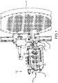
- FIG. 1 An exemplary drive apparatus 100 incorporating an automatic blockage sensor in accordance with the present disclosure is shown in FIG. 1 with a side cover open showing the set of 3 pairs of drive rollers 102 arranged for driving two flexible lances 104 in accordance with one embodiment of the present disclosure.
- the apparatus 100 includes a housing 106 in which a drive motor 108 drives each of the six drive rollers 102.
- FIG. 1 shows a drive apparatus 100 supported for guiding one or more flexible lance hoses 104 into and out of a tube in a tube sheet 110.
- the drive apparatus 100 is typically mounted on a flexible lance guide 117 which is fastened to a frame 119 that places the drive apparatus 100 in alignment with the tubes penetrating the tube sheet 110.
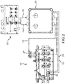
- the drive apparatus 100 is pneumatically remotely controlled via a control console 200, as shown in FIG. 2 , carried by or positioned adjacent to an operator (not shown) standing a safe distance from the apparatus 100.
- Attached to the control console 200 is an automatic blockage sensing control circuit box 220.
- This automatic blockage sensing control circuit box 220 houses an electronic monitoring circuit that monitors air motor pressure at the air motor 108 in the drive apparatus 100 shown in FIG. 1 and controls a solenoid valve also located in or adjacent to the box 220 as will be described more fully below.
- the operator preferably can stand about 20-40 feet (6-12 m) from the drive apparatus 100.
- the operator pneumatic control console 200 shown in FIG. 2 , in accordance with the present disclosure connects to an air pressure supply source line (not shown) and includes a forward line 202 connected to the air motor 108 in the drive apparatus 100, a retract, or reverse, line 204 connected to the air motor 108, and a clamp air line (not shown) that connects to an air cylinder in the housing 106 in the apparatus 100 for adjusting clamp pressure of the row of upper rollers 102 on the lance(s) 104.
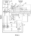
- a pair of pressure sensing lines 208 and 210 is connected directly to the forward and reverse ports on the motor 108 in the apparatus 100. These sensing lines 208 and 210 connect to a pair of pressure transducers 212 and 214 mounted in the control box 220 shown in the schematic diagram shown in FIG. 3 . Each pressure transducer 212 and 214 produces an electrical signal, either current or voltage, proportional to the pressure sensed at its particular side of the air motor 108.
- the automatic blockage sensing control box 220 includes a microcontroller 222 that utilizes the forward pressure signal from transducer 212 to determine when to institute an autostroke cycle or event. More precisely, the microcontroller 222 utilizes the signals from both transducer 212 and 214 to compute a pressure differential. When the pressure differential exceeds a threshold value the autostroke event is triggered.
- the microcontroller 222 When the pressure difference between the applied air pressure in the forward direction through line 202 sensed at the air motor 108 and the pressure sensed at the reverse port at the air motor 108 increases to a predetermined value indicative of high torque caused by the nozzles encountering a restriction or blockage in the tube(s) being cleaned, the microcontroller 222 produces an output on lines A1-A2 which closes a switch 224 to apply 12 volts DC to a solenoid valve 226 through which the forward and reverse lines 202 and 204 are connected.
- This switch 224 is preferably a solid state transistor switch.
- the solenoid valve 226 is de-energized and the forward air pressure restored to the forward port of the motor 108, at which time forward lance movement resumes if the operator is still pressing the forward control button. If the obstruction is again met, motor pressure again increases as the motor bogs down, and the process repeats.
- the automatic blockage sensor control box 220 has two potentiometers 228 and 230. Potentiometer 228 is used to adjust the threshold pressure differential at which the microcontroller 222 will close the switch 224 to energize the solenoid 226, and thereby direct forward drive pneumatic pressure to the reverse port of the air motor 108.
- the potentiometer 230 is used to adjust the length of time that pneumatic pressure is diverted to the reverse direction of air motor 108, and hence the lance retraction distance before air pressure is restored to the forward direction of the air motor 108.
- the microcontroller 222 continually monitors and compares this threshold to the sensed forward pressure via transducer 212. If the pressure difference rises above the threshold, an autostroke event is triggered. When this occurs while the operator is holding the "Hose Feed" control in the forward direction, the microcontroller 222 actuates the solenoid valve 226 which reverses the pneumatic pressure connection from the forward feed line 202 to the reverse line 204.
- This solenoid valve 226 is a 5-way two position valve that is internally piloted.
- the forward air hose 202 is connected to the pressure port of the valve 226 and the reverse air hose 204 is tee'd to both of the exhaust ports on the valve which effectively makes valve 226 a 4 way valve. Because the solenoid valve 226 is internally piloted, it will only shift when the operator is driving the drive apparatus 100 forward.
- FIG. 3 is a composite schematic of the pneumatic system between the separate control console 200 and the drive apparatus 100, and incorporates, in the dashed portion, the electronic circuitry within the automatic blockage sensor control box 220.
- the solenoid valve 226 may be mounted within the control box 220 or it may be mounted separately between the control box 220 and the drive apparatus 100. Alternatively the control box 220 and the solenoid valve 226 could be integrated completely into the housing of the drive apparatus 200.
- the power source 232 is shown as being 12 volts DC. Other supply voltages may be utilized depending on the requirements of the microcontroller 222 and the solenoid valve 226. Furthermore, the power source 232 may be a battery, a series of batteries, or, for example, a pneumatic/electric generator appropriately selected according to the power requirements of the solenoid valve 226 and the microcontroller 222. An on-off switch 234 is also provided in series with the power source 232 to remove the autostroke functionality when not desired.
- control box 220 may be physically housed within the control console 200.
- the components within the control box 220 could be integrated into the drive apparatus 100. Therefore, all such changes, alternatives and equivalents in accordance with the features and benefits described herein, are within the scope of the present disclosure. Such changes and alternatives may be introduced without departing from the scope of this disclosure as defined by the claims below and their equivalents.
Landscapes
- Engineering & Computer Science (AREA)
- Mechanical Engineering (AREA)
- General Engineering & Computer Science (AREA)
- Chemical & Material Sciences (AREA)
- Combustion & Propulsion (AREA)
- Cleaning In General (AREA)
- Nozzles (AREA)
Description
- The present disclosure is directed to high pressure fluid rotary nozzle handling systems. In particular, embodiments of the present disclosure are directed to an apparatus for advancing and retracting one or more flexible tube cleaning lances from tubes arranged in an array, such as in a heat exchanger, from a position adjacent a heat exchanger tube sheet, and automatically repetitively reversing forward lance feed movement upon encountering an obstruction within a tube or other piping system being cleaned.
- One conventional tube lancing apparatus consists of a rotating reel flexible lance hose take-up and hose dispensing apparatus that carries a predetermined length of flexible lance hose wrapped around a drum. The reel in the drum is rotated by an air motor to push the flexible lance out of the drum and into one or two heat exchanger tubes. The air motor drive can be automatically reversed upon pneumatically sensing a large air pressure increase in air pressure supplied to the forward directional side motor that occurs if the flexible lance being pushed by the reel rotation encounters an obstruction within a tube being cleaned. In this instance, when such a pressure increase is sensed, an air operated valve to the air motor drive shuts off air to the forward side of the air motor and supplies air to the opposite side of the air motor, the air motor reverses, withdrawing the lance for a predetermined time/distance. This automatic reversal of the air motor drive can then be repeated until the obstruction within the tube is removed. In this manner, the flexible lance "pecks" at a restriction, or obstruction, within the tube until the undesirable pressure increase is no longer sensed (indicating that the obstruction has been removed). This drum and reel apparatus necessarily must be somewhat remotely located from the heat exchanger tube sheet in order to accommodate the size of the drum and air drive motor apparatus.
- One problem with this approach is that it takes a substantial increase in air pressure-virtually a stall of the flexible lance within the tube, to cause the pressure to increase sufficiently to trigger reversal. Furthermore, if the flexible lance is far within a tube being cleaned, the length of hose within the tube generates resistance against the forward air motor supply pressure pushing the hose into and through the tube, which itself can cause an increase in air supply pressure without there actually being a lance stall. Hence a sufficient pressure change to trigger reversal can occur without the lance actually encountering an obstacle. Further, the forward air pressure applied in a forward direction to the drive motor in typical industrial cleaning operations generally varies widely and thus the conventional system is prone to spurious pneumatic pressure spikes and hence reversals are frequent. This is undesirable. What is needed therefore is an apparatus and method for reliably detecting a restriction within a heat exchanger tube or other piping system conduit being cleaned reliably and with precision.
-
US 3,903,912 A discloses a tube cleaning system where a pair of long, straight, small diameter, thin wall lances extend in parallel from a common cleaning fluid manifold to a pair of spray discharge heads. The lances are automatically moved into, through, and out of a pair of heat exchanger tubes by a lance drive system. The lance drive system comprises structure for moving the lances through the tubes for simultaneously applying straightening forces thereto, apparatus for controlling both the extent of movement of the lances and the flow of cleaning fluid through the lances, and circuitry for automatically reversing and re-reversing the direction of movement of the lances upon engagement of either lance with an obstruction in its respective tube. The lance drive system is mounted on a frame which includes structure for aligning the lances with a pair of heat exchanger tubes prior to each operating cycle of the tube cleaning system. -
US 2014/109936 A1 discloses a system and method for cleaning elongated tubes. An apparatus for cleaning elongated tubes includes a cart, a lance, a pressure sensing device and a propulsion device. The lance sprays material into elongated tubes to clean the elongated tubes. The cart supports the lance while the cart is moves in a rail in a forward direction and in a reverse direction. The pressure sensing device is located in the cart detects a pressure exerted on the cart as the cart moves in a forward direction in the rail. The propulsion device, upon the pressure sensing device detecting a pressure crossing a threshold value, propels the cart in the reverse direction for predetermined distance or time before again propelling the first cart in the forward direction. - A flexible lance drive apparatus according to claim 14 and an automatic blockage sensor according to claims 6 and 11 in accordance with the present disclosure directly addresses such needs. One exemplary embodiment of a flexible lance drive apparatus in accordance with the present disclosure includes a generally rectangular housing having an array of upper and lower drive rollers in an outer section each rotatably supported by an axle shaft passing laterally through spaced outer and inner walls defining a mid section of the housing. A pneumatic drive motor is housed within the mid section of the housing and is connected to each of the upper and lower drive rollers. Each lower drive roller shaft is rotatably supported in a fixed position and the upper rollers may be lowered against the lower rollers via a pneumatic cylinder to sandwich a flexible lance therebetween. This drive apparatus may be positioned adjacent an entrance into a piping system to be cleaned, such as mounted on a frame fastened to a tube sheet of a heat exchanger tube bundle.
- A control console is connected to the drive motor and to the pneumatic cylinder in the drive apparatus via forward and reverse pneumatic pressure supply I ines such that an operator can stand at the control console remotely from the drive apparatus so as to avoid the high pressure water spray from the apparatus during operation. The console has forward and reverse manual controls for directing pneumatic pressure via the pneumatic lines to forward and reverse sides of the drive motor. In this embodiment a four way solenoid valve is connected across the forward and reverse pressure lines adjacent the control console. This solenoid valve is operable to reverse the pneumatic pressure connections to the drive motor when energized.
- An automatic blockage sensing circuit, in one exemplary embodiment, is mounted within the control console or attached to it, remote from the lance drive apparatus. In other embodiments, the automatic blockage sensing circuit may be housed within the drive apparatus itself. This circuit is operable to sense, at the pneumatic drive motor, a drive motor pressure differential increase above a predetermined threshold and energize the solenoid valve to reverse the pneumatic pressure line connections to the drive motor when this occurs. This function of the automatic blockage sensing circuit and the four way solenoid valve are operable only when the forward manual control at the control console is supplying pneumatic pressure to the drive motor.
- The automatic blockage sensing circuit comprises a first pressure transducer connected to a forward air port at the drive motor and a second pressure transducer connected to a reverse air port at the drive motor via sensing lines connected directly to the drive motor, and a microcontroller configured to monitor a differential pressure between the transducers, compare the differential pressure to a predetermined threshold and generate an electrical current output when the threshold is exceeded.
- The present disclosure also describes a method of automatically clearing an obstruction encountered while cleaning one or more tubes in a tube sheet of a heat exchanger with a flexible lance drive apparatus having a linear array of driven rollers propelling one or more flexible lances into the one or more tubes, according to claim 1. This method includes sensing a pneumatic supply pressure applied to a pneumatic lance drive motor at the pneumatic lance drive motor during forward operation; sensing a pneumatic pressure at an opposite side of the drive motor during forward operation; determining a difference between the pressures; comparing the difference to a predetermined difference threshold; and reversing the supply line connections to the drive motor so as to reverse motor direction for a predetermined time interval if the difference exceeds the threshold The process may include restoring the supply line connections after the predetermined time interval and repeating the sensing, reversing and restoring operations until the difference no longer exceeds the predetermined difference threshold.
- Further features, advantages and characteristics of the embodiments of this disclosure will be apparent from reading the following detailed description when taken in conjunction with the drawing figures.
-
-
FIG. 1 is a perspective view of a flexible lance drive apparatus in accordance with the present disclosure. -
FIG. 2 is a diagram of the pneumatic connections between a remote operator's control console and the drive apparatus shown inFIG. 1 . -
FIG. 3 is a schematic electrical and pneumatic control diagram of the apparatus shown inFIG. 2 . - An
exemplary drive apparatus 100 incorporating an automatic blockage sensor in accordance with the present disclosure is shown inFIG. 1 with a side cover open showing the set of 3 pairs ofdrive rollers 102 arranged for driving twoflexible lances 104 in accordance with one embodiment of the present disclosure. Theapparatus 100 includes a housing 106 in which adrive motor 108 drives each of the sixdrive rollers 102.FIG. 1 shows adrive apparatus 100 supported for guiding one or moreflexible lance hoses 104 into and out of a tube in atube sheet 110. Thedrive apparatus 100 is typically mounted on a flexible lance guide 117 which is fastened to aframe 119 that places thedrive apparatus 100 in alignment with the tubes penetrating thetube sheet 110. - The
drive apparatus 100 is pneumatically remotely controlled via acontrol console 200, as shown inFIG. 2 , carried by or positioned adjacent to an operator (not shown) standing a safe distance from theapparatus 100. Attached to thecontrol console 200 is an automatic blockage sensingcontrol circuit box 220. This automatic blockage sensingcontrol circuit box 220 houses an electronic monitoring circuit that monitors air motor pressure at theair motor 108 in thedrive apparatus 100 shown inFIG. 1 and controls a solenoid valve also located in or adjacent to thebox 220 as will be described more fully below. - The operator preferably can stand about 20-40 feet (6-12 m) from the
drive apparatus 100. The operatorpneumatic control console 200, shown inFIG. 2 , in accordance with the present disclosure connects to an air pressure supply source line (not shown) and includes aforward line 202 connected to theair motor 108 in thedrive apparatus 100, a retract, or reverse,line 204 connected to theair motor 108, and a clamp air line (not shown) that connects to an air cylinder in the housing 106 in theapparatus 100 for adjusting clamp pressure of the row ofupper rollers 102 on the lance(s) 104. - A pair of
pressure sensing lines motor 108 in theapparatus 100. Thesesensing lines pressure transducers control box 220 shown in the schematic diagram shown inFIG. 3 . Eachpressure transducer air motor 108. - The automatic blockage
sensing control box 220 includes amicrocontroller 222 that utilizes the forward pressure signal fromtransducer 212 to determine when to institute an autostroke cycle or event. More precisely, themicrocontroller 222 utilizes the signals from bothtransducer line 202 sensed at theair motor 108 and the pressure sensed at the reverse port at theair motor 108 increases to a predetermined value indicative of high torque caused by the nozzles encountering a restriction or blockage in the tube(s) being cleaned, themicrocontroller 222 produces an output on lines A1-A2 which closes aswitch 224 to apply 12 volts DC to a solenoid valve 226 through which the forward andreverse lines switch 224 is preferably a solid state transistor switch. When the solenoid valve 226 is energized, the ports within the valve 226 redirect the forward air motor pressure to the opposite (reverse) side of theair motor 108. After a predetermined period of motor reversal, the solenoid valve 226 is de-energized and the forward air pressure restored to the forward port of themotor 108, at which time forward lance movement resumes if the operator is still pressing the forward control button. If the obstruction is again met, motor pressure again increases as the motor bogs down, and the process repeats. - The automatic blockage
sensor control box 220 has twopotentiometers Potentiometer 228 is used to adjust the threshold pressure differential at which themicrocontroller 222 will close theswitch 224 to energize the solenoid 226, and thereby direct forward drive pneumatic pressure to the reverse port of theair motor 108. Thepotentiometer 230 is used to adjust the length of time that pneumatic pressure is diverted to the reverse direction ofair motor 108, and hence the lance retraction distance before air pressure is restored to the forward direction of theair motor 108. - The
microcontroller 222 continually monitors and compares this threshold to the sensed forward pressure viatransducer 212. If the pressure difference rises above the threshold, an autostroke event is triggered. When this occurs while the operator is holding the "Hose Feed" control in the forward direction, themicrocontroller 222 actuates the solenoid valve 226 which reverses the pneumatic pressure connection from theforward feed line 202 to thereverse line 204. This solenoid valve 226 is a 5-way two position valve that is internally piloted. Theforward air hose 202 is connected to the pressure port of the valve 226 and thereverse air hose 204 is tee'd to both of the exhaust ports on the valve which effectively makes valve 226 a 4 way valve. Because the solenoid valve 226 is internally piloted, it will only shift when the operator is driving thedrive apparatus 100 forward. -
FIG. 3 is a composite schematic of the pneumatic system between theseparate control console 200 and thedrive apparatus 100, and incorporates, in the dashed portion, the electronic circuitry within the automatic blockagesensor control box 220. The solenoid valve 226 may be mounted within thecontrol box 220 or it may be mounted separately between thecontrol box 220 and thedrive apparatus 100. Alternatively thecontrol box 220 and the solenoid valve 226 could be integrated completely into the housing of thedrive apparatus 200. - In
FIG. 3 , thepower source 232 is shown as being 12 volts DC. Other supply voltages may be utilized depending on the requirements of themicrocontroller 222 and the solenoid valve 226. Furthermore, thepower source 232 may be a battery, a series of batteries, or, for example, a pneumatic/electric generator appropriately selected according to the power requirements of the solenoid valve 226 and themicrocontroller 222. An on-off switch 234 is also provided in series with thepower source 232 to remove the autostroke functionality when not desired. - Many variations are envisioned as within the scope of the present disclosure. For example, all components of the
control box 220 may be physically housed within thecontrol console 200. Alternatively, the components within thecontrol box 220 could be integrated into thedrive apparatus 100. Therefore, all such changes, alternatives and equivalents in accordance with the features and benefits described herein, are within the scope of the present disclosure. Such changes and alternatives may be introduced without departing from the scope of this disclosure as defined by the claims below and their equivalents.
Claims (15)
- A method of automatically clearing an obstruction encountered while cleaning one or more tubes in a tube sheet (110) of a heat exchanger with a flexible lance drive apparatus (100) having driven rollers propelling one or more flexible lances (104) into the one or more tubes, the method comprising:sensing a pneumatic supply pressure to a pneumatic lance drive motor (108) at one side of the pneumatic lance drive motor during forward operation;sensing a pneumatic pressure at an opposite side of the pneumatic lance drive motor at the pneumatic lance drive motor during forward operation;determining a difference between the pressures;comparing the difference to a predetermined difference threshold;reversing supply line connections to the pneumatic lance drive motor so as to reverse pneumatic lance drive motor direction for a predetermined time interval if the difference exceeds the threshold;restoring the supply line connections after the predetermined time interval; andrepeating the sensing, determining, comparing, reversing and restoring operations until the difference no longer exceeds the predetermined difference threshold.
- The method according to claim 1 wherein the predetermined time interval is adjustable.
- The method according to claim 1 or claim 2 wherein the predetermined threshold is adjustable.
- The method according to any of claims 1 to 3 wherein reversing and restoring is controlled by a microcontroller (222) operated switch (224).
- The method according to claim 4 wherein the switch (224) actuates a solenoid valve connecting the pneumatic supply connections to the pneumatic lance drive motor (108).
- An automatic blockage sensor apparatus (100) for use with a flexible high pressure cleaning lance drive motor comprising:a first pressure sensor connected to a first directional side of a bidirectional lance drive motor (108) operable to produce a first electrical pressure signal;a second pressure sensor connected to a second directional side of the bidirectional lance drive motor operable to produce a second electrical signal; anda control circuit operable to compare the first and second electrical signals, generate an output if the difference between the first and second signals exceeds a predetermined threshold, causing pneumatic pressure to the bidirectional lance drive motor to reverse direction.
- The apparatus according to claim 6 wherein the first directional side is a forward direction of the lance drive motor (108).
- The apparatus according to claim 6 or claim 7 wherein the control circuit includes a microcontroller (222) generating the output and the output closes a switch (224) in a solenoid valve power circuit.
- The apparatus according to claim 8 further comprising a sensitivity adjustment control for setting the threshold pressure differential.
- The apparatus according to claim 9 further comprising a reversal duration control connected to the microcontroller (222) for setting a duration for the reverse direction.
- An automatic blockage sensor apparatus for use with a flexible high pressure cleaning lance drive motor comprising:a first pressure sensor connected via a sensing line (208) directly to a forward port of a bidirectional lance drive motor (108) operable to produce a first electrical pressure signal;a second pressure sensor connected via a sensing line (210) directly to a reverse port of the bidirectional lance drive motor operable to produce a second electrical signal; anda control circuit operable to compare the first and second electrical signals, generate an output if the difference between the first and second signals exceeds a predetermined threshold, and cause the bidirectional lance drive motor to reverse direction.
- The apparatus according to claim 11 wherein the control circuit includes a switch (224) operated by the output to actuate a solenoid valve (226) directing pneumatic supply pressure to the lance drive motor (108).
- The apparatus according to claim 11 or claim 12 wherein the control circuit includes a microcontroller (222) for generating the output.
- A flexible lance drive apparatus comprising:a pneumatic drive motor (108) operating a plurality of drive rollers (102) to move one or more flexible lances (104) into and out of a conduit to be cleaned;a control console (200) located remotely from the drive motor, the control console being connected to the drive motor via forward (202) and reverse (204) pneumatic pressure supply lines (208, 210), the console having forward and reverse manual controls for directing pneumatic pressure to forward and reverse ports of the drive motor;a solenoid valve (226) connected across the forward and reverse pressure lines operable to reverse pneumatic pressure connections to the drive motor when energized; andan automatic blockage sensor circuit having pneumatic sensing lines (208, 210) connected directly to forward and reverse ports on the drive motor, wherein the circuit is operable to sense a drive motor pressure differential between the ports above a predetermined threshold and energize the solenoid valve to reverse the pneumatic pressure supply lines to the drive motor.
- The apparatus according to claim 14 wherein the automatic blockage sensor circuit comprises a first pressure transducer (212) connected to a forward port on the drive motor (108) and a second pressure transducer (214) connected to a reverse port on the drive motor and a microcontroller configured to monitor a differential pressure between the transducers to determine the predetermined threshold.
Applications Claiming Priority (2)
| Application Number | Priority Date | Filing Date | Title |
|---|---|---|---|
| US201562240169P | 2015-10-12 | 2015-10-12 | |
| PCT/US2016/052700 WO2017065945A1 (en) | 2015-10-12 | 2016-09-20 | Flexible lance drive apparatus with autostroke function |
Publications (3)
| Publication Number | Publication Date |
|---|---|
| EP3362195A1 EP3362195A1 (en) | 2018-08-22 |
| EP3362195A4 EP3362195A4 (en) | 2018-10-17 |
| EP3362195B1 true EP3362195B1 (en) | 2020-12-09 |
Family
ID=58498956
Family Applications (1)
| Application Number | Title | Priority Date | Filing Date |
|---|---|---|---|
| EP16855927.6A Active EP3362195B1 (en) | 2015-10-12 | 2016-09-20 | Flexible lance drive apparatus with autostroke function |
Country Status (9)
| Country | Link |
|---|---|
| US (2) | US20170102195A1 (en) |
| EP (1) | EP3362195B1 (en) |
| JP (1) | JP2018532583A (en) |
| KR (1) | KR20180054906A (en) |
| CN (1) | CN108136450A (en) |
| AU (1) | AU2016337215A1 (en) |
| BR (1) | BR112018005372B1 (en) |
| CA (1) | CA2998499A1 (en) |
| WO (1) | WO2017065945A1 (en) |
Families Citing this family (17)
| Publication number | Priority date | Publication date | Assignee | Title |
|---|---|---|---|---|
| US10890390B2 (en) | 2013-05-09 | 2021-01-12 | Terydon, Inc. | Indexer, indexer retrofit kit and method of use thereof |
| US12332670B2 (en) | 2013-05-09 | 2025-06-17 | Stoneage, Inc. | Indexer and method of use thereof |
| US11327511B2 (en) | 2013-05-09 | 2022-05-10 | Terydon, Inc. | Indexer, indexer retrofit kit and method of use thereof |
| US10408552B2 (en) * | 2013-05-09 | 2019-09-10 | Terydon, Inc. | Indexer, indexer retrofit kit and method of use thereof |
| US10401878B2 (en) | 2013-05-09 | 2019-09-03 | Terydon, Inc. | Indexer, indexer retrofit kit and method of use thereof |
| US11360494B2 (en) | 2013-05-09 | 2022-06-14 | Terydon, Inc. | Method of cleaning heat exchangers or tube bundles using a cleaning station |
| US11460258B2 (en) | 2015-10-16 | 2022-10-04 | Peinemann Equipment B.V. | System for cleaning an object such as a heat exchanger |
| US10502509B2 (en) | 2016-05-03 | 2019-12-10 | Peinemann Equipment B.V. | Method and apparatus for cleaning tubes in a rotary path |
| US11733720B2 (en) | 2016-08-30 | 2023-08-22 | Terydon, Inc. | Indexer and method of use thereof |
| NL2018861B1 (en) * | 2017-05-05 | 2018-11-14 | Peinemann Equipment Bv | Device for driving a flexible lance |
| CN109696079B (en) * | 2017-10-20 | 2020-09-04 | 中国石油化工股份有限公司 | Opposed solid particle jet distributor on-line coke cleaning device |
| US11441856B2 (en) | 2018-10-26 | 2022-09-13 | Stoneage, Inc. | Auto-indexing lance positioner apparatus and system |
| US11517947B2 (en) * | 2018-10-26 | 2022-12-06 | Stoneage, Inc. | Auto-indexing lance positioner apparatus and system |
| CA3126461C (en) * | 2019-02-20 | 2025-06-03 | Stoneage, Inc. | Flexible lance drive positioner apparatus |
| CN112284184B (en) * | 2020-10-31 | 2022-08-09 | 湖南达道新能源开发有限公司 | Cleaning and scraping device and method for inner wall of geothermal pipe |
| DE102021102410A1 (en) * | 2021-02-03 | 2022-08-04 | Lobbe Industrieservice Gmbh & Co Kg | Process and cleaning device for cleaning the inside of pipes |
| WO2025221984A1 (en) * | 2024-04-17 | 2025-10-23 | Stoneage, Inc. | E-trac tractor device and method of use |
Family Cites Families (12)
| Publication number | Priority date | Publication date | Assignee | Title |
|---|---|---|---|---|
| US3903912A (en) * | 1970-09-17 | 1975-09-09 | Hydro Vel Services Inc | Tube cleaning system |
| DE3710340A1 (en) * | 1987-03-28 | 1988-10-06 | Albert Kipfelsberger | POWER SCREWDRIVER WITH TORQUE LIMIT |
| US5423917A (en) * | 1993-02-12 | 1995-06-13 | Garcia, Jr.; Ralph | Method for cleaning heat exchanger tubes by creating shock wave and mixing the liquid with injected air |
| NL1012806C2 (en) * | 1999-08-11 | 2001-02-13 | Peinemann Equipment Bv | Drive device for flexible lance. |
| US6681839B1 (en) * | 2001-02-23 | 2004-01-27 | Brent A. Balzer | Heat exchanger exchange-tube cleaning lance positioning system |
| NL1024113C2 (en) * | 2003-08-14 | 2005-02-15 | Peinemann Equipment Bv | Lance device with reciprocating drive. |
| BRPI0907081A2 (en) * | 2008-03-20 | 2015-07-07 | Hydrochem Ind Services Inc | System, method and device for automated heat exchanger tube cleaning |
| CN201331059Y (en) * | 2009-01-05 | 2009-10-21 | 向西成 | Device for adjusting and automatic controlling new type water-coal-slurry lance boom |
| US8628629B2 (en) * | 2010-11-02 | 2014-01-14 | Terydon, Inc. | Method and apparatus for cleaning elongated tubes |
| US9328979B2 (en) * | 2013-07-30 | 2016-05-03 | Veolia Es Industrial Services, Inc. | Heat exchanger cleaning tool with three axis control |
| PL228360B1 (en) * | 2014-03-18 | 2018-03-30 | Inst Energetyki | Method and installation for selective, non-catalytic reduction of NOX in stoker-fired boilers |
| CN204610221U (en) * | 2014-12-12 | 2015-09-02 | 汉弓股份有限公司 | The control gear of pump |
-
2016
- 2016-09-20 CN CN201680057990.XA patent/CN108136450A/en active Pending
- 2016-09-20 CA CA2998499A patent/CA2998499A1/en not_active Abandoned
- 2016-09-20 AU AU2016337215A patent/AU2016337215A1/en not_active Abandoned
- 2016-09-20 US US15/270,926 patent/US20170102195A1/en not_active Abandoned
- 2016-09-20 BR BR112018005372-4A patent/BR112018005372B1/en active IP Right Grant
- 2016-09-20 WO PCT/US2016/052700 patent/WO2017065945A1/en not_active Ceased
- 2016-09-20 KR KR1020187013366A patent/KR20180054906A/en not_active Withdrawn
- 2016-09-20 EP EP16855927.6A patent/EP3362195B1/en active Active
- 2016-09-20 JP JP2018518583A patent/JP2018532583A/en active Pending
-
2018
- 2018-08-31 US US16/119,586 patent/US20180372432A1/en not_active Abandoned
Also Published As
| Publication number | Publication date |
|---|---|
| JP2018532583A (en) | 2018-11-08 |
| KR20180054906A (en) | 2018-05-24 |
| CA2998499A1 (en) | 2017-04-20 |
| AU2016337215A1 (en) | 2018-04-05 |
| BR112018005372A2 (en) | 2018-10-09 |
| EP3362195A1 (en) | 2018-08-22 |
| US20170102195A1 (en) | 2017-04-13 |
| US20180372432A1 (en) | 2018-12-27 |
| EP3362195A4 (en) | 2018-10-17 |
| BR112018005372B1 (en) | 2021-10-26 |
| CN108136450A (en) | 2018-06-08 |
| WO2017065945A1 (en) | 2017-04-20 |
Similar Documents
| Publication | Publication Date | Title |
|---|---|---|
| US20180372432A1 (en) | Flexible lance drive apparatus with autostroke function | |
| US11874077B2 (en) | Flexible lance drive apparatus with autostroke function | |
| US10048027B2 (en) | Method and device for cleaning tube bundles | |
| US5636403A (en) | Tube cleaning apparatus | |
| CA2491960A1 (en) | Multi-media rotating sootblower and automatic industrial boiler cleaning system | |
| AU2003234881A1 (en) | Automated Tube Cleaner | |
| SG10202112217UA (en) | Robotic Solar Panel Cleaning System | |
| EP1112434B1 (en) | Device for application of dope on male threads | |
| EP0424487B1 (en) | Apparatus for projecting a flexible cable through a tube to be cleaned | |
| JP2020014982A (en) | Inner surface cleaning device for vertical pipe | |
| US5265671A (en) | Apparatus for mechanically projecting devices through tubes | |
| HK1249877A1 (en) | Flexible lance drive apparatus with autostroke function | |
| KR100451101B1 (en) | A cleaner of tube and pipe | |
| JPH1054695A (en) | Pipe feeding and winding device | |
| WO1992007786A1 (en) | Apparatus for projecting devices through tubes and conduits | |
| US7066188B2 (en) | Interior sewer pipeline scarifying apparatus | |
| KR102584593B1 (en) | Apparatus for cleaning of heat exchanger | |
| CA2485819C (en) | Interior sewer pipeline scarifying apparatus | |
| KR20210157047A (en) | Liquid injection apparatus of selection type | |
| GB2586068A (en) | Tube Cleaning System and Method | |
| JP3046964U (en) | Tube cleaning device | |
| NL2006375C2 (en) | CLEANING DEVICE. | |
| US20050150531A1 (en) | Interior sewer pipeline scarifying apparatus | |
| JP2590189Y2 (en) | Cleaning equipment | |
| JPH0646542Y2 (en) | Air-conditioning duct cleaning device |
Legal Events
| Date | Code | Title | Description |
|---|---|---|---|
| STAA | Information on the status of an ep patent application or granted ep patent |
Free format text: STATUS: THE INTERNATIONAL PUBLICATION HAS BEEN MADE |
|
| PUAI | Public reference made under article 153(3) epc to a published international application that has entered the european phase |
Free format text: ORIGINAL CODE: 0009012 |
|
| STAA | Information on the status of an ep patent application or granted ep patent |
Free format text: STATUS: REQUEST FOR EXAMINATION WAS MADE |
|
| 17P | Request for examination filed |
Effective date: 20180316 |
|
| AK | Designated contracting states |
Kind code of ref document: A1 Designated state(s): AL AT BE BG CH CY CZ DE DK EE ES FI FR GB GR HR HU IE IS IT LI LT LU LV MC MK MT NL NO PL PT RO RS SE SI SK SM TR |
|
| AX | Request for extension of the european patent |
Extension state: BA ME |
|
| REG | Reference to a national code |
Ref country code: DE Ref legal event code: R079 Ref document number: 602016049628 Country of ref document: DE Free format text: PREVIOUS MAIN CLASS: B08B0009027000 Ipc: F28G0015000000 |
|
| A4 | Supplementary search report drawn up and despatched |
Effective date: 20180914 |
|
| RIC1 | Information provided on ipc code assigned before grant |
Ipc: F28G 3/16 20060101ALI20180911BHEP Ipc: F28G 15/04 20060101ALI20180911BHEP Ipc: F28G 15/00 20060101AFI20180911BHEP |
|
| DAV | Request for validation of the european patent (deleted) | ||
| DAX | Request for extension of the european patent (deleted) | ||
| GRAP | Despatch of communication of intention to grant a patent |
Free format text: ORIGINAL CODE: EPIDOSNIGR1 |
|
| STAA | Information on the status of an ep patent application or granted ep patent |
Free format text: STATUS: GRANT OF PATENT IS INTENDED |
|
| INTG | Intention to grant announced |
Effective date: 20200721 |
|
| GRAS | Grant fee paid |
Free format text: ORIGINAL CODE: EPIDOSNIGR3 |
|
| GRAA | (expected) grant |
Free format text: ORIGINAL CODE: 0009210 |
|
| STAA | Information on the status of an ep patent application or granted ep patent |
Free format text: STATUS: THE PATENT HAS BEEN GRANTED |
|
| AK | Designated contracting states |
Kind code of ref document: B1 Designated state(s): AL AT BE BG CH CY CZ DE DK EE ES FI FR GB GR HR HU IE IS IT LI LT LU LV MC MK MT NL NO PL PT RO RS SE SI SK SM TR |
|
| REG | Reference to a national code |
Ref country code: GB Ref legal event code: FG4D |
|
| REG | Reference to a national code |
Ref country code: AT Ref legal event code: REF Ref document number: 1343878 Country of ref document: AT Kind code of ref document: T Effective date: 20201215 Ref country code: CH Ref legal event code: EP |
|
| REG | Reference to a national code |
Ref country code: DE Ref legal event code: R096 Ref document number: 602016049628 Country of ref document: DE |
|
| REG | Reference to a national code |
Ref country code: IE Ref legal event code: FG4D |
|
| REG | Reference to a national code |
Ref country code: NL Ref legal event code: FP |
|
| PG25 | Lapsed in a contracting state [announced via postgrant information from national office to epo] |
Ref country code: RS Free format text: LAPSE BECAUSE OF FAILURE TO SUBMIT A TRANSLATION OF THE DESCRIPTION OR TO PAY THE FEE WITHIN THE PRESCRIBED TIME-LIMIT Effective date: 20201209 Ref country code: NO Free format text: LAPSE BECAUSE OF FAILURE TO SUBMIT A TRANSLATION OF THE DESCRIPTION OR TO PAY THE FEE WITHIN THE PRESCRIBED TIME-LIMIT Effective date: 20210309 Ref country code: FI Free format text: LAPSE BECAUSE OF FAILURE TO SUBMIT A TRANSLATION OF THE DESCRIPTION OR TO PAY THE FEE WITHIN THE PRESCRIBED TIME-LIMIT Effective date: 20201209 Ref country code: GR Free format text: LAPSE BECAUSE OF FAILURE TO SUBMIT A TRANSLATION OF THE DESCRIPTION OR TO PAY THE FEE WITHIN THE PRESCRIBED TIME-LIMIT Effective date: 20210310 |
|
| REG | Reference to a national code |
Ref country code: AT Ref legal event code: MK05 Ref document number: 1343878 Country of ref document: AT Kind code of ref document: T Effective date: 20201209 |
|
| PG25 | Lapsed in a contracting state [announced via postgrant information from national office to epo] |
Ref country code: LV Free format text: LAPSE BECAUSE OF FAILURE TO SUBMIT A TRANSLATION OF THE DESCRIPTION OR TO PAY THE FEE WITHIN THE PRESCRIBED TIME-LIMIT Effective date: 20201209 Ref country code: BG Free format text: LAPSE BECAUSE OF FAILURE TO SUBMIT A TRANSLATION OF THE DESCRIPTION OR TO PAY THE FEE WITHIN THE PRESCRIBED TIME-LIMIT Effective date: 20210309 Ref country code: SE Free format text: LAPSE BECAUSE OF FAILURE TO SUBMIT A TRANSLATION OF THE DESCRIPTION OR TO PAY THE FEE WITHIN THE PRESCRIBED TIME-LIMIT Effective date: 20201209 |
|
| PG25 | Lapsed in a contracting state [announced via postgrant information from national office to epo] |
Ref country code: HR Free format text: LAPSE BECAUSE OF FAILURE TO SUBMIT A TRANSLATION OF THE DESCRIPTION OR TO PAY THE FEE WITHIN THE PRESCRIBED TIME-LIMIT Effective date: 20201209 |
|
| REG | Reference to a national code |
Ref country code: LT Ref legal event code: MG9D |
|
| PG25 | Lapsed in a contracting state [announced via postgrant information from national office to epo] |
Ref country code: EE Free format text: LAPSE BECAUSE OF FAILURE TO SUBMIT A TRANSLATION OF THE DESCRIPTION OR TO PAY THE FEE WITHIN THE PRESCRIBED TIME-LIMIT Effective date: 20201209 Ref country code: CZ Free format text: LAPSE BECAUSE OF FAILURE TO SUBMIT A TRANSLATION OF THE DESCRIPTION OR TO PAY THE FEE WITHIN THE PRESCRIBED TIME-LIMIT Effective date: 20201209 Ref country code: SM Free format text: LAPSE BECAUSE OF FAILURE TO SUBMIT A TRANSLATION OF THE DESCRIPTION OR TO PAY THE FEE WITHIN THE PRESCRIBED TIME-LIMIT Effective date: 20201209 Ref country code: LT Free format text: LAPSE BECAUSE OF FAILURE TO SUBMIT A TRANSLATION OF THE DESCRIPTION OR TO PAY THE FEE WITHIN THE PRESCRIBED TIME-LIMIT Effective date: 20201209 Ref country code: PT Free format text: LAPSE BECAUSE OF FAILURE TO SUBMIT A TRANSLATION OF THE DESCRIPTION OR TO PAY THE FEE WITHIN THE PRESCRIBED TIME-LIMIT Effective date: 20210409 Ref country code: RO Free format text: LAPSE BECAUSE OF FAILURE TO SUBMIT A TRANSLATION OF THE DESCRIPTION OR TO PAY THE FEE WITHIN THE PRESCRIBED TIME-LIMIT Effective date: 20201209 Ref country code: SK Free format text: LAPSE BECAUSE OF FAILURE TO SUBMIT A TRANSLATION OF THE DESCRIPTION OR TO PAY THE FEE WITHIN THE PRESCRIBED TIME-LIMIT Effective date: 20201209 |
|
| PG25 | Lapsed in a contracting state [announced via postgrant information from national office to epo] |
Ref country code: PL Free format text: LAPSE BECAUSE OF FAILURE TO SUBMIT A TRANSLATION OF THE DESCRIPTION OR TO PAY THE FEE WITHIN THE PRESCRIBED TIME-LIMIT Effective date: 20201209 Ref country code: AT Free format text: LAPSE BECAUSE OF FAILURE TO SUBMIT A TRANSLATION OF THE DESCRIPTION OR TO PAY THE FEE WITHIN THE PRESCRIBED TIME-LIMIT Effective date: 20201209 |
|
| REG | Reference to a national code |
Ref country code: DE Ref legal event code: R097 Ref document number: 602016049628 Country of ref document: DE |
|
| PG25 | Lapsed in a contracting state [announced via postgrant information from national office to epo] |
Ref country code: IS Free format text: LAPSE BECAUSE OF FAILURE TO SUBMIT A TRANSLATION OF THE DESCRIPTION OR TO PAY THE FEE WITHIN THE PRESCRIBED TIME-LIMIT Effective date: 20210409 |
|
| PLBE | No opposition filed within time limit |
Free format text: ORIGINAL CODE: 0009261 |
|
| STAA | Information on the status of an ep patent application or granted ep patent |
Free format text: STATUS: NO OPPOSITION FILED WITHIN TIME LIMIT |
|
| PG25 | Lapsed in a contracting state [announced via postgrant information from national office to epo] |
Ref country code: IT Free format text: LAPSE BECAUSE OF FAILURE TO SUBMIT A TRANSLATION OF THE DESCRIPTION OR TO PAY THE FEE WITHIN THE PRESCRIBED TIME-LIMIT Effective date: 20201209 Ref country code: AL Free format text: LAPSE BECAUSE OF FAILURE TO SUBMIT A TRANSLATION OF THE DESCRIPTION OR TO PAY THE FEE WITHIN THE PRESCRIBED TIME-LIMIT Effective date: 20201209 |
|
| 26N | No opposition filed |
Effective date: 20210910 |
|
| PG25 | Lapsed in a contracting state [announced via postgrant information from national office to epo] |
Ref country code: DK Free format text: LAPSE BECAUSE OF FAILURE TO SUBMIT A TRANSLATION OF THE DESCRIPTION OR TO PAY THE FEE WITHIN THE PRESCRIBED TIME-LIMIT Effective date: 20201209 Ref country code: SI Free format text: LAPSE BECAUSE OF FAILURE TO SUBMIT A TRANSLATION OF THE DESCRIPTION OR TO PAY THE FEE WITHIN THE PRESCRIBED TIME-LIMIT Effective date: 20201209 |
|
| PGFP | Annual fee paid to national office [announced via postgrant information from national office to epo] |
Ref country code: DE Payment date: 20210810 Year of fee payment: 6 |
|
| PG25 | Lapsed in a contracting state [announced via postgrant information from national office to epo] |
Ref country code: ES Free format text: LAPSE BECAUSE OF FAILURE TO SUBMIT A TRANSLATION OF THE DESCRIPTION OR TO PAY THE FEE WITHIN THE PRESCRIBED TIME-LIMIT Effective date: 20201209 |
|
| REG | Reference to a national code |
Ref country code: CH Ref legal event code: PL |
|
| REG | Reference to a national code |
Ref country code: BE Ref legal event code: MM Effective date: 20210930 |
|
| GBPC | Gb: european patent ceased through non-payment of renewal fee |
Effective date: 20210920 |
|
| PG25 | Lapsed in a contracting state [announced via postgrant information from national office to epo] |
Ref country code: IS Free format text: LAPSE BECAUSE OF FAILURE TO SUBMIT A TRANSLATION OF THE DESCRIPTION OR TO PAY THE FEE WITHIN THE PRESCRIBED TIME-LIMIT Effective date: 20210409 Ref country code: MC Free format text: LAPSE BECAUSE OF FAILURE TO SUBMIT A TRANSLATION OF THE DESCRIPTION OR TO PAY THE FEE WITHIN THE PRESCRIBED TIME-LIMIT Effective date: 20201209 |
|
| PG25 | Lapsed in a contracting state [announced via postgrant information from national office to epo] |
Ref country code: LU Free format text: LAPSE BECAUSE OF NON-PAYMENT OF DUE FEES Effective date: 20210920 Ref country code: IE Free format text: LAPSE BECAUSE OF NON-PAYMENT OF DUE FEES Effective date: 20210920 Ref country code: GB Free format text: LAPSE BECAUSE OF NON-PAYMENT OF DUE FEES Effective date: 20210920 Ref country code: FR Free format text: LAPSE BECAUSE OF NON-PAYMENT OF DUE FEES Effective date: 20210930 Ref country code: BE Free format text: LAPSE BECAUSE OF NON-PAYMENT OF DUE FEES Effective date: 20210930 |
|
| PG25 | Lapsed in a contracting state [announced via postgrant information from national office to epo] |
Ref country code: LI Free format text: LAPSE BECAUSE OF NON-PAYMENT OF DUE FEES Effective date: 20210930 Ref country code: CH Free format text: LAPSE BECAUSE OF NON-PAYMENT OF DUE FEES Effective date: 20210930 |
|
| REG | Reference to a national code |
Ref country code: DE Ref legal event code: R119 Ref document number: 602016049628 Country of ref document: DE |
|
| PG25 | Lapsed in a contracting state [announced via postgrant information from national office to epo] |
Ref country code: CY Free format text: LAPSE BECAUSE OF FAILURE TO SUBMIT A TRANSLATION OF THE DESCRIPTION OR TO PAY THE FEE WITHIN THE PRESCRIBED TIME-LIMIT Effective date: 20201209 |
|
| P01 | Opt-out of the competence of the unified patent court (upc) registered |
Effective date: 20230602 |
|
| PG25 | Lapsed in a contracting state [announced via postgrant information from national office to epo] |
Ref country code: HU Free format text: LAPSE BECAUSE OF FAILURE TO SUBMIT A TRANSLATION OF THE DESCRIPTION OR TO PAY THE FEE WITHIN THE PRESCRIBED TIME-LIMIT; INVALID AB INITIO Effective date: 20160920 Ref country code: DE Free format text: LAPSE BECAUSE OF NON-PAYMENT OF DUE FEES Effective date: 20230401 |
|
| PG25 | Lapsed in a contracting state [announced via postgrant information from national office to epo] |
Ref country code: MK Free format text: LAPSE BECAUSE OF FAILURE TO SUBMIT A TRANSLATION OF THE DESCRIPTION OR TO PAY THE FEE WITHIN THE PRESCRIBED TIME-LIMIT Effective date: 20201209 |
|
| PG25 | Lapsed in a contracting state [announced via postgrant information from national office to epo] |
Ref country code: TR Free format text: LAPSE BECAUSE OF FAILURE TO SUBMIT A TRANSLATION OF THE DESCRIPTION OR TO PAY THE FEE WITHIN THE PRESCRIBED TIME-LIMIT Effective date: 20201209 |
|
| PG25 | Lapsed in a contracting state [announced via postgrant information from national office to epo] |
Ref country code: MT Free format text: LAPSE BECAUSE OF FAILURE TO SUBMIT A TRANSLATION OF THE DESCRIPTION OR TO PAY THE FEE WITHIN THE PRESCRIBED TIME-LIMIT Effective date: 20201209 |
|
| PGFP | Annual fee paid to national office [announced via postgrant information from national office to epo] |
Ref country code: NL Payment date: 20250704 Year of fee payment: 10 |