EP3361965B1 - Patella fracture reduction plates - Google Patents
Patella fracture reduction plates Download PDFInfo
- Publication number
- EP3361965B1 EP3361965B1 EP16784761.5A EP16784761A EP3361965B1 EP 3361965 B1 EP3361965 B1 EP 3361965B1 EP 16784761 A EP16784761 A EP 16784761A EP 3361965 B1 EP3361965 B1 EP 3361965B1
- Authority
- EP
- European Patent Office
- Prior art keywords
- plate
- patella
- patellar
- plate body
- attachment holes
- Prior art date
- Legal status (The legal status is an assumption and is not a legal conclusion. Google has not performed a legal analysis and makes no representation as to the accuracy of the status listed.)
- Active
Links
Images





Classifications
-
- A—HUMAN NECESSITIES
- A61—MEDICAL OR VETERINARY SCIENCE; HYGIENE
- A61B—DIAGNOSIS; SURGERY; IDENTIFICATION
- A61B17/00—Surgical instruments, devices or methods
- A61B17/56—Surgical instruments or methods for treatment of bones or joints; Devices specially adapted therefor
- A61B17/58—Surgical instruments or methods for treatment of bones or joints; Devices specially adapted therefor for osteosynthesis, e.g. bone plates, screws or setting implements
- A61B17/68—Internal fixation devices, including fasteners and spinal fixators, even if a part thereof projects from the skin
- A61B17/80—Cortical plates, i.e. bone plates; Instruments for holding or positioning cortical plates, or for compressing bones attached to cortical plates
- A61B17/8061—Cortical plates, i.e. bone plates; Instruments for holding or positioning cortical plates, or for compressing bones attached to cortical plates specially adapted for particular bones
-
- A—HUMAN NECESSITIES
- A61—MEDICAL OR VETERINARY SCIENCE; HYGIENE
- A61B—DIAGNOSIS; SURGERY; IDENTIFICATION
- A61B17/00—Surgical instruments, devices or methods
- A61B17/16—Instruments for performing osteoclasis; Drills or chisels for bones; Trepans
- A61B17/17—Guides or aligning means for drills, mills, pins or wires
- A61B17/1739—Guides or aligning means for drills, mills, pins or wires specially adapted for particular parts of the body
- A61B17/1764—Guides or aligning means for drills, mills, pins or wires specially adapted for particular parts of the body for the knee
- A61B17/1767—Guides or aligning means for drills, mills, pins or wires specially adapted for particular parts of the body for the knee for the patella
-
- A—HUMAN NECESSITIES
- A61—MEDICAL OR VETERINARY SCIENCE; HYGIENE
- A61B—DIAGNOSIS; SURGERY; IDENTIFICATION
- A61B17/00—Surgical instruments, devices or methods
- A61B17/56—Surgical instruments or methods for treatment of bones or joints; Devices specially adapted therefor
- A61B17/58—Surgical instruments or methods for treatment of bones or joints; Devices specially adapted therefor for osteosynthesis, e.g. bone plates, screws or setting implements
- A61B17/68—Internal fixation devices, including fasteners and spinal fixators, even if a part thereof projects from the skin
- A61B17/80—Cortical plates, i.e. bone plates; Instruments for holding or positioning cortical plates, or for compressing bones attached to cortical plates
- A61B17/8085—Cortical plates, i.e. bone plates; Instruments for holding or positioning cortical plates, or for compressing bones attached to cortical plates with pliable or malleable elements or having a mesh-like structure, e.g. small strips
Definitions
- Fracture reduction devices are known in the art. For long bones, such as the femur, tibia, and fibula, fractures can potentially be reduced using plating systems. For bony areas where the bone includes curvature in multiple axes, and areas where the skin is especially taut to the bone, use of plating systems can be challenging. In such bony areas, such as the patella, other reduction methods have been employed. One such method or system includes high tension mesh plates. Another approach used in the prior art includes wiring or cord systems. In the case of mesh apparatuses, the systems generally require the surgeon to cut the mesh plate to size and fit the mesh for a give patient's patella. Wiring and cabling systems generally require the surgeon to route the wires or cables through channels created in the patella, and/or require the surgeon to wrap the wire or cable around at least a portion of the patella.
- the present inventors have recognized, among other things, that a problem to be solved is providing a fracture reduction system for the patella that does not require time to individually fit the system for individual patients before or during operation. It would also be desirable to have a system that does not require wire in order to create tension across a fracture, while still maintaining a low profile solution.
- the present disclosure can help provide a solution to these problems with a strong, flexible plate that is generally a universal fit for patellas of various patients.
- the system further can provide a solution by utilizing a monolithic plate that does not require the use of wires in order to reduce the fracture (though wires can be used with the presently described system where appropriate and desirable).
- the present disclosure includes a first device for patella fracture reduction.
- the device can include a patellar plate body formed from a monolithic material.
- the patellar plate body can comprise a central portion and a peripheral portion at least partially surrounding the central portion.
- the central portion can include a plurality of plate attachment holes disposed therein.
- the peripheral portion can comprise a plurality of tabs. Each of the plurality of tabs can be coupled to the central portion via a connector portion that is less than about 80% of a plate thickness of the patellar plate body.
- Each tab can include a tab attachment hole disposed therein.
- Each tab can be selectively detachable from the patellar plate body.
- the patellar plate body can be contoured to fit substantially any patella.
- the present disclosure includes a second device for patella fracture reduction.
- the fracture reduction device can include a curved perimeter plate contoured to a perimeter of substantially any patella.
- the curved perimeter plate can define a plate length between a first end and a second end thereof that extends along at least a portion of the perimeter of a patella.
- the curved perimeter plate can include a plurality of connection regions positioned along the plate length and a plurality of securing regions positioned along the plate length. At least some of the connection regions can be positioned between two adjacent securing regions.
- Each securing region can include an attachment hole disposed therein.
- the present disclosure further includes systems comprising a patellar plate body and a curved perimeter plate.
- Such systems can further comprise at least one guide insert removably disposed in at least one of a patellar plate attachment hole, a tab attachment hole, and a perimeter plate attachment hole.
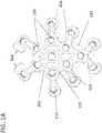
- FIGS 1A-1C illustrate top, perspective and side views of one exemplary plate for patella fracture reduction according to the present disclosure.
- Plate 100 can include a patellar plate body 102.
- Patellar plate body 102 can be, in some examples, contoured to conform to a curved surface of substantially any patella and can extend across at least one fracture in the patella. Alternatively or additionally, plate body 102 can extend across two, three or more fractures on the patella in close proximity to one another.
- Patellar plate body 102 can be formed from a monolithic material and, additionally or alternatively, can comprise a central portion 107 and a peripheral portion 108 at least partially surrounding the central portion 107.
- the central portion 107 can include a plurality of plate attachment holes 104 disposed therein.
- the plate attachment holes 104 can receive a securing element, such as, for example and without limitation, a locking screw, a non-locking screw, and the like.
- the peripheral portion 108 of the plate 100 can comprise a plurality of selectively removable tabs 106.
- Each tab 106 can be coupled to the central portion 107 via a connector portion 109 that can have a thickness that is less than about 80% of a plate thickness of the patellar plate body 102. As a result of the reduced thickness, the tab can be more easily removed.
- At least some of tabs 106 can include a tab attachment hole 110 disposed therein.
- Each tab 106 can be selectively detached by, for example and without limitation, bending, deformation, and the like.
- Each tab attachment hole 110 can receive a securing element in the same fashion as attachment holes 104.
- Tab members 106 can be cleanly removed using a few bending cycles or clipping the tab members off with, e.g., plate cutters or a wire cutter.
- Plate attachment holes 104 and tab attachment holes 110 can be sized and shaped to receive a securing element in order to secure at least a portion of the plate 100 to the surface of the patella. As shown in Figure 1 and in other figures herein, any one of the attachment holes can be round, such as circular or oval, although other shapes (e.g., square, hexagonal, etc.) are also contemplated.
- Patellar plate body 102 can comprise any number of suitable shapes.
- plate body 102 can comprise a pentagonal shape (as illustrated by dashed line pentagon 112).
- the plate body 102 can have the shape of an upside-down pear or a tear.
- the patellar plate body can be sized and shaped in a horizontal and vertical direction, and, additionally or alternatively, three-dimensionally contoured to fit a patella and, more particularly, universally fit any patella.
- Patellar plate body 102 can also include any suitable number of plate attachment holes 104 and tab attachment holes 110 (collectively referred to as "attachment holes") necessary to sufficiently secure the plate 100 to the patella and aid in reducing a fracture of the patella.
- the plate body 102 can include at least four attachment holes, at least six attachment holes, at least eight attachment holes, at least ten attachment holes, or more.
- Attachment holes 104, 110 can accept a securing element that can have a diameter of between about 2.0mm and about 3.0mm. In an example, attachment holes 104 can accept a 2.5mm screw.
- the securing element can be any suitable fastening member, such as a locking screw, a non-locking screw, or the like.
- Patellar plate body 102 can be, in an example, made of a material that is moldable to a curved shape but also strong.
- plate body 102 can be made of titanium or a titanium alloy.
- the plate 100 can be monolithic and both the central portion 107 and the peripheral portion 108 can be titanium or a titanium alloy.
- Patellar plate body 102 can have a low profile such that it does not extend a great distance away from the surface of the patella after implantation.
- plate body 102 can have a thickness of less than about 3mm, less than about 2mm thick, or less than about 1.6mm thick.
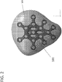
- An illustration of plate 100 positioned over the front surface of a patella 10 is provided in Figure 2 .
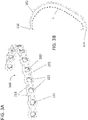
- Fracture reduction device 200 can comprise a curved perimeter plate 202 that can be, in various examples, contoured to a perimeter of substantially any patella.
- the curved perimeter plate 202 can define a plate length L between a first end 214 and a second end 216 thereof that extends along at least a portion of the perimeter of a patella.
- the plate 202 can comprise a plurality of connection regions 218 that can be positioned along the plate length L and a plurality of securing regions 220 positioned along the plate length. At least some (or potentially all) of the connection regions 218 can be positioned between two adjacent securing regions 218.
- Each securing region 220 can include an attachment hole 222 disposed therein.
- the curved perimeter plate 202 can have a low profile, e.g., the plate can have a thickness of less than 3.0mm, less than 2.0 mm, or less than 1.6mm.
- the curved perimeter plate 202 can be configured to extend along greater than about one-third of the perimeter of the patella and less than about two-thirds of the perimeter of the patella. For example, the plate 202 can extend along approximately one-half of the perimeter of the patella.
- An example of a half-perimeter fracture device 200 positioned on the perimeter of a patella 10 is illustrated in Figure 4 .
- a curved perimeter plate 302 can extend along greater than about one-fifth of the perimeter of the patella and less than about one-third of the perimeter of the patella. For example plate 302 can extend along approximately one-quarter of the perimeter of the patella.
- An example of a quarter-perimeter fracture device 300 positioned on the perimeter of a patella 10 is illustrated in Figure 6 .
- the devices can be universal to substantially any patella and such that they are not left/right, top/bottom side, or medial/lateral specific.
- the curvature of the devices can be such that they can generally be positioned on either the medial or lateral side of the patella, and, with regard to the perimeter plates, on the top side or bottom side of the patella along the perimeter.
- the attachment holes 222 of curved perimeter plate 202 can accept a securing device, such as a screw, that can have a diameter of between about 2.0mm and about 3.0mm.
- the attachment holes 222 can accept a screw having a diameter of 2.5mm.
- the curved perimeter plate 202 can include at least four attachment holes, at least six attachment holes, at least eight attachment holes, or more.
- Curved perimeter plate 202 can be, in an example, made of a material that is moldable to a curved shape but also strong.
- curved perimeter plate 202 can be made of titanium or a titanium alloy.
- any of the presently described fracture reduction devices can be used with a guide system that can aid in accurate placement of the plate 102, 202 on the patella.
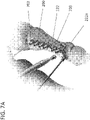
- An example of a guide system is illustrated in Figures 7A-7C .
- Attachment holes 222 of fracture reduction device 200 can receive guide inserts 703.
- Guide inserts 703 can be placed into attachment holes 222 prior to the securing element being inserted through the attachment holes.
- the guide inserts 703 can also define a trajectory for the securing element through the attachment hole. Once the appropriate alignment of the fracture device 200 has been achieved relative to the patella, the guide inserts 703 can be removed.
- FIG. 7A illustrates a first exemplary guide insert 703a being removed from an attachment hole 222.
- Figure 7B illustrates a next step in which a securing element 705 can be inserted into the first attachment hole 222a after the first guide insert has been removed from the hole.
- the other guide inserts 703 can be left in respective attachment holes 222 during insertion of securing devices into adjacent attachment holes (e.g. 222a) in order to ensure that the fracture device remains appropriately positioned.
- Figure 7C illustrates the construction with securing element 7505 fully inserted through attachment hole 222 and into the patella. Though shown in Figures 7A-7C with respect to fracture reduction device 200 configured for use on the perimeter of the patella, the plate 100 of Figures 1A-1C can also be designed such that attachment holes 104 are configured to receive guide inserts of the type described herein.
- a fracture reduction device 400 comprising a plate 402 can include at least two anchor holes 424, such as anchor holes 424a and 424b.
- Figures 8A-8C further illustrate that the plate 402 can also include selectively removable tabs 406 as described above with respect to tabs 106.
- At least one of the tabs 406 can include a tab attachment hole 410 disposed therein.
- multiple or each of the tab members 406 can include a tab attachment hole 410 disposed therein.
- Tab attachment hole(s) 410 can accept a securing element.
- the anchor holes can be configured to receive sutures that can be secured to the patella and to the anchor holes to create tension across the patella fracture.
- the anchor holes can be used to anchor a braided fixation system, for example, a braided polyethylene fixation system such as the Zimmer Biomet ZipLoop TM Technology (Zimmer Biomet, Warsaw, Indiana) that creates tension with an opposing edge of the patella.
Landscapes
- Health & Medical Sciences (AREA)
- Orthopedic Medicine & Surgery (AREA)
- Surgery (AREA)
- Life Sciences & Earth Sciences (AREA)
- Biomedical Technology (AREA)
- Public Health (AREA)
- Veterinary Medicine (AREA)
- Engineering & Computer Science (AREA)
- Nuclear Medicine, Radiotherapy & Molecular Imaging (AREA)
- Heart & Thoracic Surgery (AREA)
- Medical Informatics (AREA)
- Molecular Biology (AREA)
- Animal Behavior & Ethology (AREA)
- General Health & Medical Sciences (AREA)
- Neurology (AREA)
- Dentistry (AREA)
- Oral & Maxillofacial Surgery (AREA)
- Surgical Instruments (AREA)
- Prostheses (AREA)
Description
- This application claims the benefit of priority to
U.S. Provisional Application Serial No. 62/241,863, filed October 15, 2015 - Fracture reduction devices are known in the art. For long bones, such as the femur, tibia, and fibula, fractures can potentially be reduced using plating systems. For bony areas where the bone includes curvature in multiple axes, and areas where the skin is especially taut to the bone, use of plating systems can be challenging. In such bony areas, such as the patella, other reduction methods have been employed. One such method or system includes high tension mesh plates. Another approach used in the prior art includes wiring or cord systems. In the case of mesh apparatuses, the systems generally require the surgeon to cut the mesh plate to size and fit the mesh for a give patient's patella. Wiring and cabling systems generally require the surgeon to route the wires or cables through channels created in the patella, and/or require the surgeon to wrap the wire or cable around at least a portion of the patella.
- This section provides a general summary of the disclosure, and is not a comprehensive disclosure of its full scope or all of its features.
- The present inventors have recognized, among other things, that a problem to be solved is providing a fracture reduction system for the patella that does not require time to individually fit the system for individual patients before or during operation. It would also be desirable to have a system that does not require wire in order to create tension across a fracture, while still maintaining a low profile solution. The present disclosure can help provide a solution to these problems with a strong, flexible plate that is generally a universal fit for patellas of various patients. The system further can provide a solution by utilizing a monolithic plate that does not require the use of wires in order to reduce the fracture (though wires can be used with the presently described system where appropriate and desirable).
- The present disclosure includes a first device for patella fracture reduction. The device can include a patellar plate body formed from a monolithic material. The patellar plate body can comprise a central portion and a peripheral portion at least partially surrounding the central portion. The central portion can include a plurality of plate attachment holes disposed therein. The peripheral portion can comprise a plurality of tabs. Each of the plurality of tabs can be coupled to the central portion via a connector portion that is less than about 80% of a plate thickness of the patellar plate body. Each tab can include a tab attachment hole disposed therein. Each tab can be selectively detachable from the patellar plate body. The patellar plate body can be contoured to fit substantially any patella.
- The present disclosure includes a second device for patella fracture reduction. The fracture reduction device can include a curved perimeter plate contoured to a perimeter of substantially any patella. The curved perimeter plate can define a plate length between a first end and a second end thereof that extends along at least a portion of the perimeter of a patella. The curved perimeter plate can include a plurality of connection regions positioned along the plate length and a plurality of securing regions positioned along the plate length. At least some of the connection regions can be positioned between two adjacent securing regions. Each securing region can include an attachment hole disposed therein.
- The present disclosure further includes systems comprising a patellar plate body and a curved perimeter plate. Such systems can further comprise at least one guide insert removably disposed in at least one of a patellar plate attachment hole, a tab attachment hole, and a perimeter plate attachment hole.
- Further areas of applicability will become apparent from the description provided herein. The description and specific examples in this summary are intended for purposes of illustration only and are not intended to limit the scope of the present disclosure.
- The drawings described herein are for illustrative purposes only of selected embodiments and not all possible implementations, and are not intended to limit the scope of the present disclosure. The invention is illustrated in the
figures 1-2 and7A-8C . The remaining figures illustrate examples that are useful for understanding the invention. -
Figure 1A illustrates a top view of a plate for patella fracture reduction, in accordance with at least one example of the present disclosure. -
Figure 1B illustrates a perspective view of a plate for patella fracture reduction, in accordance with at least one example of the present disclosure. -
Figure 1C illustrates a side view of a plate for patella fracture reduction, in accordance with at least one example of the present disclosure. -
Figure 2 illustrates a front view of a plate for patella fracture reduction positioned on the surface of a patella, in accordance with at least one example of the present disclosure. -
Figure 3A illustrates a perspective view of a fracture reduction device, in accordance with at least one example of the present disclosure. -
Figure 3B illustrates a top view of a fracture reduction device, in accordance with at least one example of the present disclosure. -
Figure 4 illustrates a front view of a patella with a fracture reduction device positioned on the perimeter of a patella, in accordance with at least one example of the present disclosure. -
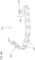
Figure 5A illustrates a perspective of a fracture reduction device, in accordance with at least one example of the present disclosure. -
Figure 5B illustrates a top view of a fracture reduction device, in accordance with at least one example of the present disclosure. -
Figure 6 illustrates a front view of a patella with a fracture reduction device positioned on the perimeter of the patella, in accordance with at least one example of the present disclosure. -
Figures 7A-7B provide perspective views of a fracture reduction device with alignment guides, in accordance with at least one example of the present disclosure. -
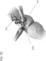
Figure 7C illustrates a close-up view of a fracture reduction device with alignment guides and a securing element, in accordance with at least one example of the present disclosure. -
Figure 8A illustrates a perspective view of a fracture reduction device, in accordance with at least one example of the present disclosure. -
Figure 8B illustrates a side view of a fracture reduction device, in accordance with at least one example of the present disclosure. -
Figure 8C illustrates a top view of a fracture reduction device, in accordance with at least one example of the present disclosure. - Example embodiments will now be described more fully with reference to the accompanying drawings.
- The present disclosure provides for devices and systems for reducing fractures of the patella including plates.
Figures 1A-1C illustrate top, perspective and side views of one exemplary plate for patella fracture reduction according to the present disclosure.Plate 100 can include apatellar plate body 102.Patellar plate body 102 can be, in some examples, contoured to conform to a curved surface of substantially any patella and can extend across at least one fracture in the patella. Alternatively or additionally,plate body 102 can extend across two, three or more fractures on the patella in close proximity to one another.Patellar plate body 102 can be formed from a monolithic material and, additionally or alternatively, can comprise acentral portion 107 and aperipheral portion 108 at least partially surrounding thecentral portion 107. Thecentral portion 107 can include a plurality ofplate attachment holes 104 disposed therein. Theplate attachment holes 104 can receive a securing element, such as, for example and without limitation, a locking screw, a non-locking screw, and the like. - The
peripheral portion 108 of theplate 100 can comprise a plurality of selectivelyremovable tabs 106. Eachtab 106 can be coupled to thecentral portion 107 via aconnector portion 109 that can have a thickness that is less than about 80% of a plate thickness of thepatellar plate body 102. As a result of the reduced thickness, the tab can be more easily removed. At least some oftabs 106 can include atab attachment hole 110 disposed therein. Eachtab 106 can be selectively detached by, for example and without limitation, bending, deformation, and the like. Eachtab attachment hole 110 can receive a securing element in the same fashion as attachment holes 104. In any one or combination of the cases that atab 106 is not filled with a securing element, poses no benefit, causes overhang, exceeds the surface of the bone, etc., the surgeon can remove thetab member 106.Tab members 106 can be cleanly removed using a few bending cycles or clipping the tab members off with, e.g., plate cutters or a wire cutter. - Plate attachment holes 104 and tab attachment holes 110 can be sized and shaped to receive a securing element in order to secure at least a portion of the
plate 100 to the surface of the patella. As shown inFigure 1 and in other figures herein, any one of the attachment holes can be round, such as circular or oval, although other shapes (e.g., square, hexagonal, etc.) are also contemplated. -
Patellar plate body 102 can comprise any number of suitable shapes. In an example, as illustrated inFigure 1A ,plate body 102 can comprise a pentagonal shape (as illustrated by dashed line pentagon 112). In another example, theplate body 102 can have the shape of an upside-down pear or a tear. In another example, the patellar plate body can be sized and shaped in a horizontal and vertical direction, and, additionally or alternatively, three-dimensionally contoured to fit a patella and, more particularly, universally fit any patella.Patellar plate body 102 can also include any suitable number of plate attachment holes 104 and tab attachment holes 110 (collectively referred to as "attachment holes") necessary to sufficiently secure theplate 100 to the patella and aid in reducing a fracture of the patella. In various examples, theplate body 102 can include at least four attachment holes, at least six attachment holes, at least eight attachment holes, at least ten attachment holes, or more. Attachment holes 104, 110 can accept a securing element that can have a diameter of between about 2.0mm and about 3.0mm. In an example, attachment holes 104 can accept a 2.5mm screw. The securing element can be any suitable fastening member, such as a locking screw, a non-locking screw, or the like.Patellar plate body 102 can be, in an example, made of a material that is moldable to a curved shape but also strong. For example,plate body 102 can be made of titanium or a titanium alloy. In an example, theplate 100 can be monolithic and both thecentral portion 107 and theperipheral portion 108 can be titanium or a titanium alloy. -
Patellar plate body 102 can have a low profile such that it does not extend a great distance away from the surface of the patella after implantation. In various examples,plate body 102 can have a thickness of less than about 3mm, less than about 2mm thick, or less than about 1.6mm thick. An illustration ofplate 100 positioned over the front surface of apatella 10 is provided inFigure 2 . - In another example illustrated in
Figures 3A-3B , the present disclosure relates to a second fracture reduction device.Fracture reduction device 200 can comprise acurved perimeter plate 202 that can be, in various examples, contoured to a perimeter of substantially any patella. Thecurved perimeter plate 202 can define a plate length L between afirst end 214 and asecond end 216 thereof that extends along at least a portion of the perimeter of a patella. Theplate 202 can comprise a plurality ofconnection regions 218 that can be positioned along the plate length L and a plurality of securingregions 220 positioned along the plate length. At least some (or potentially all) of theconnection regions 218 can be positioned between two adjacent securingregions 218. Each securingregion 220 can include anattachment hole 222 disposed therein. As withpatellar plate body 102 above, thecurved perimeter plate 202 can have a low profile, e.g., the plate can have a thickness of less than 3.0mm, less than 2.0 mm, or less than 1.6mm. - In an example illustrated in
Figures 3A and 3B , thecurved perimeter plate 202 can be configured to extend along greater than about one-third of the perimeter of the patella and less than about two-thirds of the perimeter of the patella. For example, theplate 202 can extend along approximately one-half of the perimeter of the patella. An example of a half-perimeter fracture device 200 positioned on the perimeter of apatella 10 is illustrated inFigure 4 . Alternatively, as illustrated withfracture reduction device 300 ofFigures 5A and 5B , acurved perimeter plate 302 can extend along greater than about one-fifth of the perimeter of the patella and less than about one-third of the perimeter of the patella. Forexample plate 302 can extend along approximately one-quarter of the perimeter of the patella. An example of a quarter-perimeter fracture device 300 positioned on the perimeter of apatella 10 is illustrated inFigure 6 . - One benefit of all presently described fracture reduction devices is that the devices can be universal to substantially any patella and such that they are not left/right, top/bottom side, or medial/lateral specific. For example, the curvature of the devices can be such that they can generally be positioned on either the medial or lateral side of the patella, and, with regard to the perimeter plates, on the top side or bottom side of the patella along the perimeter.
- Returning to
Figures 3A and 3B , as with the example described inFigures 1A-1C , the attachment holes 222 ofcurved perimeter plate 202 can accept a securing device, such as a screw, that can have a diameter of between about 2.0mm and about 3.0mm. In an example, the attachment holes 222 can accept a screw having a diameter of 2.5mm. Thecurved perimeter plate 202 can include at least four attachment holes, at least six attachment holes, at least eight attachment holes, or more.Curved perimeter plate 202 can be, in an example, made of a material that is moldable to a curved shape but also strong. For example,curved perimeter plate 202 can be made of titanium or a titanium alloy. - In various examples, any of the presently described fracture reduction devices can be used with a guide system that can aid in accurate placement of the
plate Figures 7A-7C . Attachment holes 222 offracture reduction device 200 can receive guide inserts 703. Guide inserts 703 can be placed into attachment holes 222 prior to the securing element being inserted through the attachment holes. The guide inserts 703 can also define a trajectory for the securing element through the attachment hole. Once the appropriate alignment of thefracture device 200 has been achieved relative to the patella, the guide inserts 703 can be removed. After a givenguide insert 703 is removed, a corresponding securing element can be inserted into theattachment hole 703 in order to securely affix thefracture device 200 to the patella.Figure 7A illustrates a first exemplary guide insert 703a being removed from anattachment hole 222.Figure 7B illustrates a next step in which a securingelement 705 can be inserted into thefirst attachment hole 222a after the first guide insert has been removed from the hole. The other guide inserts 703 can be left in respective attachment holes 222 during insertion of securing devices into adjacent attachment holes (e.g. 222a) in order to ensure that the fracture device remains appropriately positioned.Figure 7C illustrates the construction with securing element 7505 fully inserted throughattachment hole 222 and into the patella. Though shown inFigures 7A-7C with respect to fracturereduction device 200 configured for use on the perimeter of the patella, theplate 100 ofFigures 1A-1C can also be designed such that attachment holes 104 are configured to receive guide inserts of the type described herein. - In another example, as illustrated in
Figures 8A-8C , afracture reduction device 400 comprising aplate 402 can include at least twoanchor holes 424, such as anchor holes 424a and 424b.Figures 8A-8C further illustrate that theplate 402 can also include selectivelyremovable tabs 406 as described above with respect totabs 106. At least one of thetabs 406 can include atab attachment hole 410 disposed therein. Alternatively, multiple or each of thetab members 406 can include atab attachment hole 410 disposed therein. Tab attachment hole(s) 410 can accept a securing element. - Alternatively, other types of securing devices can be used to secure the anchor holes to the patella. For example, the anchor holes can be configured to receive sutures that can be secured to the patella and to the anchor holes to create tension across the patella fracture. Additionally or alternatively, the anchor holes can be used to anchor a braided fixation system, for example, a braided polyethylene fixation system such as the Zimmer Biomet ZipLoop™ Technology (Zimmer Biomet, Warsaw, Indiana) that creates tension with an opposing edge of the patella.
- The above detailed description includes references to the accompanying drawings, which form a part of the detailed description. The drawings show, by way of illustration, specific embodiments in which the invention can be practiced. These embodiments are also referred to herein as "examples." Such examples can include elements in addition to those shown or described. However, the present inventors also contemplate examples in which only those elements shown or described are provided. Moreover, the present inventors also contemplate examples using any combination or permutation of those elements shown or described (or one or more aspects thereof), either with respect to a particular example (or one or more aspects thereof), or with respect to other examples (or one or more aspects thereof) shown or described herein.
- In this document, the terms "a" or "an" are used, as is common in patent documents, to include one or more than one, independent of any other instances or usages of "at least one" or "one or more." In this document, the term "or" is used to refer to a nonexclusive or, such that "A or B" includes "A but not B," "B but not A," and "A and B," unless otherwise indicated. In this document, the terms "including" and "in which" are used as the plain-English equivalents of the respective terms "comprising" and "wherein." Also, in the following claims, the terms "including" and "comprising" are open-ended, that is, a system, device, article, composition, formulation, or process that includes elements in addition to those listed after such a term in a claim are still deemed to fall within the scope of that claim. Moreover, in the following claims, the terms "first," "second," and "third," etc. are used merely as labels, and are not intended to impose numerical requirements on their objects.
- The above description is intended to be illustrative, and not restrictive. For example, the above-described examples (or one or more aspects thereof) may be used in combination with each other. Other embodiments can be used, such as by one of ordinary skill in the art upon reviewing the above description. The Abstract is provided to comply with 37 C.F.R. §1.72(b), to allow the reader to quickly ascertain the nature of the technical disclosure. It is submitted with the understanding that it will not be used to interpret or limit the scope or meaning of the claims. Also, in the above Detailed Description, various features may be grouped together to streamline the disclosure. This should not be interpreted as intending that an unclaimed disclosed feature is essential to any claim. Rather, inventive subject matter may lie in less than all features of a particular disclosed embodiment. Thus, the following claims are hereby incorporated into the Detailed Description as examples or embodiments, with each claim standing on its own as a separate embodiment, and it is contemplated that such embodiments can be combined with each other in various combinations or permutations. The scope of the invention should be determined with reference to the appended claims, along with the full scope of equivalents to which such claims are entitled.
Claims (13)
- A device, comprising:a patellar plate body (102) formed from a monolithic material and comprising a central portion (107) and a peripheral portion (108) at least partially surrounding the central portion,the central portion including a plurality of plate attachment holes (104) disposed therein,the peripheral portion comprising a plurality of tabs (106),each tab coupled to the central portion via a connector portion (109),each tab being selectively detachable from the patellar plate body,wherein the patellar plate body is sized in at least a horizontal and a vertical direction to fit a patella (10), andwherein the connector portion has a thickness that is less than 80% of a plate thickness of the patellar plate body.
- The plate of claim 1, wherein the central portion comprises a pentagonal shape (112).
- The plate of claim 1 or 2, wherein one plate attachment hole (104) or one tab attachment hole (110) accepts a screw having a diameter of between about 2.0mm and about 3.0mm.
- The plate of any one of claims 1-3, wherein the plate body includes at least six attachment holes.
- The plate of any one of claims 1-4, wherein the plate body includes at least eight attachment holes.
- The plate of any one of claims 1-5, wherein the monolithic material comprises titanium or a titanium alloy.
- The plate of any one of claims 1-6, wherein the patellar plate body is less than about 3.0 mm thick.
- The plate of any one of claims 1-7, wherein the patellar plate body is less than about 2.0 mm thick.
- The plate of any one of claims 1-8, wherein the patellar plate body is less than about 1.6 mm thick.
- The plate of any one of claims 1-9, wherein each of the plate attachment holes further comprises a guide insert for aiding in initially securing the patellar plate body to the patella prior to a securing element being inserted through a respective one of the plate attachment holes.
- The plate of claim 10, wherein the guide insert is removable prior to inserting the securing element through the respective one of the plate attachment holes.
- The plate of any one of claims 1-11, wherein the securing element is a locking screw or a non-locking screw.
- The plate of any one of claims 1-12, wherein each tab includes a tab attachment hole (110) disposed therein.
Applications Claiming Priority (2)
| Application Number | Priority Date | Filing Date | Title |
|---|---|---|---|
| US201562241863P | 2015-10-15 | 2015-10-15 | |
| PCT/US2016/057193 WO2017066682A1 (en) | 2015-10-15 | 2016-10-14 | Patella fracture reduction plates |
Publications (2)
| Publication Number | Publication Date |
|---|---|
| EP3361965A1 EP3361965A1 (en) | 2018-08-22 |
| EP3361965B1 true EP3361965B1 (en) | 2022-09-21 |
Family
ID=57178585
Family Applications (1)
| Application Number | Title | Priority Date | Filing Date |
|---|---|---|---|
| EP16784761.5A Active EP3361965B1 (en) | 2015-10-15 | 2016-10-14 | Patella fracture reduction plates |
Country Status (7)
| Country | Link |
|---|---|
| US (2) | US10327824B2 (en) |
| EP (1) | EP3361965B1 (en) |
| JP (1) | JP6577675B2 (en) |
| CN (1) | CN108366803B (en) |
| AU (1) | AU2016337382B2 (en) |
| CA (1) | CA3001856C (en) |
| WO (1) | WO2017066682A1 (en) |
Families Citing this family (37)
| Publication number | Priority date | Publication date | Assignee | Title |
|---|---|---|---|---|
| WO2017041091A1 (en) | 2015-09-04 | 2017-03-09 | DePuy Synthes Products, Inc. | Patella bone plate |
| US10130402B2 (en) | 2015-09-25 | 2018-11-20 | Globus Medical, Inc. | Bone fixation devices having a locking feature |
| JP6577675B2 (en) | 2015-10-15 | 2019-09-18 | バイオメット マニュファクチャリング,リミティド ライアビリティ カンパニー | Patella fracture reduction plate |
| US9974581B2 (en) | 2015-11-20 | 2018-05-22 | Globus Medical, Inc. | Expandable intramedullary systems and methods of using the same |
| US9795411B2 (en) | 2016-03-02 | 2017-10-24 | Globus Medical, Inc. | Fixators for bone stabilization and associated systems and methods |
| US10531905B2 (en) | 2016-04-19 | 2020-01-14 | Globus Medical, Inc. | Implantable compression screws |
| US11432857B2 (en) | 2016-08-17 | 2022-09-06 | Globus Medical, Inc. | Stabilization systems |
| US11197701B2 (en) * | 2016-08-17 | 2021-12-14 | Globus Medical, Inc. | Stabilization systems |
| US10299847B2 (en) | 2016-09-22 | 2019-05-28 | Globus Medical, Inc. | Systems and methods for intramedullary nail implantation |
| DE102016124528A1 (en) * | 2016-12-15 | 2018-06-21 | Karl Leibinger Medizintechnik Gmbh & Co. Kg | Implant for osteosynthesis and implant kit with implant |
| US12318122B2 (en) | 2017-09-13 | 2025-06-03 | Globus Medical, Inc. | Bone stabilization systems |
| US10856920B2 (en) | 2017-09-13 | 2020-12-08 | Globus Medical Inc. | Bone stabilization systems |
| US11096730B2 (en) | 2017-09-13 | 2021-08-24 | Globus Medical Inc. | Bone stabilization systems |
| CN107928776A (en) * | 2017-12-28 | 2018-04-20 | 江苏荷普医疗科技股份有限公司 | The universal bone plate of kneecap multiaxis |
| US11224468B2 (en) | 2018-03-02 | 2022-01-18 | Globus Medical, Inc. | Distal tibial plating system |
| US11071570B2 (en) | 2018-03-02 | 2021-07-27 | Globus Medical, Inc. | Distal tibial plating system |
| US11141172B2 (en) | 2018-04-11 | 2021-10-12 | Globus Medical, Inc. | Method and apparatus for locking a drill guide in a polyaxial hole |
| EP3801322B1 (en) * | 2018-05-25 | 2024-08-07 | Ortho Solutions Inc. | Systems for fusion of anatomical joints |
| US10765462B2 (en) * | 2018-09-11 | 2020-09-08 | DePuy Synthes Products, Inc. | Patella bone plate and methods of fixation |
| US12295628B2 (en) | 2018-11-01 | 2025-05-13 | Howmedica Osteonics Corp. | Device for fixating orthopedic injury |
| US11202663B2 (en) | 2019-02-13 | 2021-12-21 | Globus Medical, Inc. | Proximal humeral stabilization systems and methods thereof |
| EP3747384B1 (en) | 2019-06-03 | 2022-12-14 | Stryker European Holdings I, LLC | Rib plate and rib plate system |
| US12185995B2 (en) | 2019-10-09 | 2025-01-07 | Globus Medical, Inc. | Bone stabilization systems |
| US11129627B2 (en) | 2019-10-30 | 2021-09-28 | Globus Medical, Inc. | Method and apparatus for inserting a bone plate |
| US11723647B2 (en) | 2019-12-17 | 2023-08-15 | Globus Medical, Inc. | Syndesmosis fixation assembly |
| CN111358543B (en) * | 2020-03-19 | 2022-08-19 | 周继辉 | Steel plate device for patellar lower pole fracture |
| CN111616786B (en) * | 2020-04-19 | 2022-10-18 | 河南科技大学第一附属医院 | Bone-knitting device for patellar fracture |
| CN111529034A (en) * | 2020-05-20 | 2020-08-14 | 重庆市中医院 | Internal fixing device for patellar lower-pole fracture and screw fixing method |
| CN112155700A (en) * | 2020-09-22 | 2021-01-01 | 江苏艾迪尔医疗科技股份有限公司 | Patella hook-and-loop system |
| US12011199B2 (en) | 2020-10-15 | 2024-06-18 | DePuy Synthes Products, Inc. | Bone plate, bone plate system, and method of using the same |
| US11806029B2 (en) | 2021-01-06 | 2023-11-07 | DePuy Synthes Products, Inc. | Locking trocar and method of using the same |
| US12064150B2 (en) | 2022-01-19 | 2024-08-20 | Globus Medical Inc. | System and method for treating bone fractures |
| US12478365B2 (en) | 2022-08-24 | 2025-11-25 | Globus Medical, Inc. | Systems, devices and methods for implanting suture buttons |
| US20250143758A1 (en) * | 2023-11-02 | 2025-05-08 | Globus Medical, Inc. | Fracture plating systems |
| CH721505B1 (en) * | 2024-01-11 | 2025-08-29 | Ittenbach Maximilian | Device for the osteosynthetic treatment of bone fractures, especially patella fractures |
| USD1116113S1 (en) * | 2024-04-30 | 2026-03-03 | DePuy Synthes Products, Inc. | Bone plate |
| USD1120328S1 (en) | 2024-04-30 | 2026-03-24 | DePuy Synthes Products, Inc. | Bone plate |
Family Cites Families (38)
| Publication number | Priority date | Publication date | Assignee | Title |
|---|---|---|---|---|
| US4923471A (en) * | 1989-10-17 | 1990-05-08 | Timesh, Inc. | Bone fracture reduction and fixation devices with identity tags |
| US5468242A (en) * | 1993-11-19 | 1995-11-21 | Leibinger Gmbh | Form-fitting mesh implant |
| US5814048A (en) * | 1996-05-03 | 1998-09-29 | Sofamor Danek Properties, Inc. | Cranioplasty plates and method of installation |
| US5718705A (en) * | 1996-07-16 | 1998-02-17 | Sammarco; Giacomo J. | Internal fixation plate |
| US5766176A (en) * | 1996-09-11 | 1998-06-16 | Walter Lorenz Surgical, Inc. | Formable mesh |
| US5690631A (en) * | 1996-09-11 | 1997-11-25 | Walter Lorenz Surgical, Inc. | Multi-configurable plating system |
| US5853413A (en) * | 1997-04-18 | 1998-12-29 | Bristol-Myers Squibb Company | Wrist fusion plate |
| US6123709A (en) * | 1997-07-25 | 2000-09-26 | Jones; Andrew R. | Bone buttress plate and method of using same |
| US6620332B2 (en) * | 2001-01-25 | 2003-09-16 | Tecomet, Inc. | Method for making a mesh-and-plate surgical implant |
| US20050261780A1 (en) * | 2001-06-08 | 2005-11-24 | Harri Heino | Form-fitting bioabsorbable mesh implant |
| FR2827500B1 (en) * | 2001-07-17 | 2004-04-02 | Tornier Sa | PLATE OF OSTEOSYNTHESIS OF THE UPPER END OF THE HUMERUS |
| US7717946B2 (en) * | 2004-06-07 | 2010-05-18 | Degima Gmbh | Polymeric plate bendable without thermal energy and methods of manufacture |
| US7785355B2 (en) * | 2004-10-20 | 2010-08-31 | Synthes Usa, Llc | System for rib fixation |
| US8118846B2 (en) * | 2005-01-28 | 2012-02-21 | Orthohelix Surgical Designs, Inc. | Orthopedic plates for use in clavicle repair and methods for their use |
| US20060235397A1 (en) * | 2005-03-31 | 2006-10-19 | Roy Sanders | Navicular fixation device |
| US20060276896A1 (en) * | 2005-06-02 | 2006-12-07 | Medicinelodge, Inc. | Bone implants with integrated line locks |
| US7935126B2 (en) * | 2006-03-20 | 2011-05-03 | Depuy Products, Inc. | Bone plate shaping system |
| US8142434B2 (en) * | 2007-10-17 | 2012-03-27 | Stryker Trauma Gmbh | Cam-locking of cable for fracture plate |
| ATE527949T1 (en) * | 2007-11-02 | 2011-10-15 | Depuy Products Inc | FIXATION SYSTEM FOR ELBOW Fracture |
| US8317842B2 (en) * | 2007-11-30 | 2012-11-27 | Biomet C.V. | Distal tibia plating system |
| US8403968B2 (en) * | 2007-12-26 | 2013-03-26 | Illuminoss Medical, Inc. | Apparatus and methods for repairing craniomaxillofacial bones using customized bone plates |
| US8496665B2 (en) * | 2008-02-13 | 2013-07-30 | Biomet C.V. | Drill sleeve |
| CA2643678C (en) * | 2008-06-12 | 2016-01-19 | Socovar, Societe En Commandite | Orthopaedic fixation component and method |
| US8337533B2 (en) * | 2008-06-20 | 2012-12-25 | Osteomed Llc | Locking plate benders |
| US8551107B2 (en) * | 2009-10-15 | 2013-10-08 | Biomet, C.V. | Bending tool and method for reshaping a bone plate |
| EP2494934B1 (en) * | 2011-03-04 | 2015-12-16 | Stryker Trauma SA | Bone plate |
| EP2693963B1 (en) * | 2011-04-01 | 2015-06-03 | Synthes GmbH | Posterior vertebral plating system |
| JP6240076B2 (en) * | 2011-09-30 | 2017-11-29 | アキュート・イノヴェーションズ・エルエルシー | Bone fixation system with opposing mounting parts |
| US8551143B2 (en) * | 2011-10-11 | 2013-10-08 | Brent Lane Norris | Low profile periarticular tension band plating system with soft tissue neutralization cable tunnel/channel |
| US10004603B2 (en) * | 2012-08-23 | 2018-06-26 | DePuy Synthes Products, Inc. | Bone implant |
| US9993273B2 (en) * | 2013-01-16 | 2018-06-12 | Mako Surgical Corp. | Bone plate and tracking device using a bone plate for attaching to a patient's anatomy |
| US9517097B2 (en) * | 2013-04-17 | 2016-12-13 | Stc.Unm | Low-profile, high tension mesh plate for subcutaneous fracture fixation |
| US9888950B2 (en) * | 2013-11-18 | 2018-02-13 | Biomet C.V. | Plate benders and system |
| AU2015222798B2 (en) * | 2014-02-27 | 2019-10-10 | Exotoe Llc | Bone fusion/fixation device and related systems and methods |
| JP6936146B2 (en) * | 2015-01-07 | 2021-09-15 | トリース メディカル コンセプツ,インコーポレイティド | Bone plate fixation system and method |
| WO2017041091A1 (en) * | 2015-09-04 | 2017-03-09 | DePuy Synthes Products, Inc. | Patella bone plate |
| JP6577675B2 (en) | 2015-10-15 | 2019-09-18 | バイオメット マニュファクチャリング,リミティド ライアビリティ カンパニー | Patella fracture reduction plate |
| US10335210B2 (en) * | 2016-01-21 | 2019-07-02 | Biomet Manufacturing, Llc | Anatomic plates for medial proximal tibia |
-
2016
- 2016-10-14 JP JP2018539240A patent/JP6577675B2/en active Active
- 2016-10-14 EP EP16784761.5A patent/EP3361965B1/en active Active
- 2016-10-14 CN CN201680067167.7A patent/CN108366803B/en active Active
- 2016-10-14 AU AU2016337382A patent/AU2016337382B2/en active Active
- 2016-10-14 CA CA3001856A patent/CA3001856C/en active Active
- 2016-10-14 WO PCT/US2016/057193 patent/WO2017066682A1/en not_active Ceased
- 2016-10-14 US US15/294,528 patent/US10327824B2/en active Active
-
2019
- 2019-05-15 US US16/413,300 patent/US11039868B2/en active Active
Also Published As
| Publication number | Publication date |
|---|---|
| US11039868B2 (en) | 2021-06-22 |
| WO2017066682A1 (en) | 2017-04-20 |
| JP2018531137A (en) | 2018-10-25 |
| CN108366803A (en) | 2018-08-03 |
| US20170105775A1 (en) | 2017-04-20 |
| CA3001856C (en) | 2020-08-04 |
| AU2016337382A1 (en) | 2018-05-17 |
| AU2016337382B2 (en) | 2019-03-07 |
| CN108366803B (en) | 2021-05-14 |
| US10327824B2 (en) | 2019-06-25 |
| EP3361965A1 (en) | 2018-08-22 |
| JP6577675B2 (en) | 2019-09-18 |
| CA3001856A1 (en) | 2017-04-20 |
| US20190262046A1 (en) | 2019-08-29 |
Similar Documents
| Publication | Publication Date | Title |
|---|---|---|
| US11039868B2 (en) | Patella fracture reduction plates | |
| JP2018531137A6 (en) | Patella fracture reduction plate | |
| US10918422B2 (en) | Method and apparatus for inhibiting proximal junctional failure | |
| KR101768706B1 (en) | Ulna osteotomy system | |
| US8518042B2 (en) | Orthopedic plate assembly for a distal radius having re-contouring features and method for using same | |
| EP3481314B1 (en) | Chest wall repair device | |
| EP1958580A1 (en) | Orthopaedic trauma bone plate kit | |
| US20160324555A1 (en) | Intra-osseous plate system and method | |
| US8961574B2 (en) | Bone plate with hook portion | |
| AU2015284585A1 (en) | Metacarpal neck plate | |
| US20130072988A1 (en) | Aiming on Plate | |
| US20140081340A1 (en) | Apparatus And Method For Sternal Closure | |
| US20150342656A1 (en) | Fracture reduction structure | |
| EP4023179B1 (en) | A system comprising a foam structure and a surgical fixation device | |
| US20210353341A1 (en) | Wedge plates and methods of use | |
| JP2021000454A (en) | Fracture fixation system and its method | |
| US9265544B2 (en) | Sternal plate type sternal closure comprising an integral severing site member | |
| EP3023067A1 (en) | Strut plate and cabling system | |
| US20060264932A1 (en) | Attachment to bone | |
| EP3422971B1 (en) | Bracket for external fixation of bones | |
| EP2938300B1 (en) | Orthopedic bone plate and locking tab apparatus | |
| US11471294B2 (en) | Transcortal bone joint fusion system | |
| KR100339843B1 (en) | Internal fixing metal plate for remedy of fracture bone | |
| US20150119946A1 (en) | Community Orthopedic Fixation Device, System and Method |
Legal Events
| Date | Code | Title | Description |
|---|---|---|---|
| STAA | Information on the status of an ep patent application or granted ep patent |
Free format text: STATUS: UNKNOWN |
|
| STAA | Information on the status of an ep patent application or granted ep patent |
Free format text: STATUS: THE INTERNATIONAL PUBLICATION HAS BEEN MADE |
|
| PUAI | Public reference made under article 153(3) epc to a published international application that has entered the european phase |
Free format text: ORIGINAL CODE: 0009012 |
|
| STAA | Information on the status of an ep patent application or granted ep patent |
Free format text: STATUS: REQUEST FOR EXAMINATION WAS MADE |
|
| 17P | Request for examination filed |
Effective date: 20180515 |
|
| AK | Designated contracting states |
Kind code of ref document: A1 Designated state(s): AL AT BE BG CH CY CZ DE DK EE ES FI FR GB GR HR HU IE IS IT LI LT LU LV MC MK MT NL NO PL PT RO RS SE SI SK SM TR |
|
| AX | Request for extension of the european patent |
Extension state: BA ME |
|
| DAV | Request for validation of the european patent (deleted) | ||
| DAX | Request for extension of the european patent (deleted) | ||
| GRAP | Despatch of communication of intention to grant a patent |
Free format text: ORIGINAL CODE: EPIDOSNIGR1 |
|
| STAA | Information on the status of an ep patent application or granted ep patent |
Free format text: STATUS: GRANT OF PATENT IS INTENDED |
|
| INTG | Intention to grant announced |
Effective date: 20220401 |
|
| GRAS | Grant fee paid |
Free format text: ORIGINAL CODE: EPIDOSNIGR3 |
|
| GRAA | (expected) grant |
Free format text: ORIGINAL CODE: 0009210 |
|
| STAA | Information on the status of an ep patent application or granted ep patent |
Free format text: STATUS: THE PATENT HAS BEEN GRANTED |
|
| AK | Designated contracting states |
Kind code of ref document: B1 Designated state(s): AL AT BE BG CH CY CZ DE DK EE ES FI FR GB GR HR HU IE IS IT LI LT LU LV MC MK MT NL NO PL PT RO RS SE SI SK SM TR |
|
| REG | Reference to a national code |
Ref country code: GB Ref legal event code: FG4D |
|
| REG | Reference to a national code |
Ref country code: CH Ref legal event code: EP |
|
| REG | Reference to a national code |
Ref country code: DE Ref legal event code: R096 Ref document number: 602016075171 Country of ref document: DE |
|
| REG | Reference to a national code |
Ref country code: IE Ref legal event code: FG4D |
|
| REG | Reference to a national code |
Ref country code: AT Ref legal event code: REF Ref document number: 1519582 Country of ref document: AT Kind code of ref document: T Effective date: 20221015 |
|
| REG | Reference to a national code |
Ref country code: LT Ref legal event code: MG9D |
|
| REG | Reference to a national code |
Ref country code: NL Ref legal event code: MP Effective date: 20220921 |
|
| PG25 | Lapsed in a contracting state [announced via postgrant information from national office to epo] |
Ref country code: SE Free format text: LAPSE BECAUSE OF FAILURE TO SUBMIT A TRANSLATION OF THE DESCRIPTION OR TO PAY THE FEE WITHIN THE PRESCRIBED TIME-LIMIT Effective date: 20220921 Ref country code: RS Free format text: LAPSE BECAUSE OF FAILURE TO SUBMIT A TRANSLATION OF THE DESCRIPTION OR TO PAY THE FEE WITHIN THE PRESCRIBED TIME-LIMIT Effective date: 20220921 Ref country code: NO Free format text: LAPSE BECAUSE OF FAILURE TO SUBMIT A TRANSLATION OF THE DESCRIPTION OR TO PAY THE FEE WITHIN THE PRESCRIBED TIME-LIMIT Effective date: 20221221 Ref country code: LV Free format text: LAPSE BECAUSE OF FAILURE TO SUBMIT A TRANSLATION OF THE DESCRIPTION OR TO PAY THE FEE WITHIN THE PRESCRIBED TIME-LIMIT Effective date: 20220921 Ref country code: LT Free format text: LAPSE BECAUSE OF FAILURE TO SUBMIT A TRANSLATION OF THE DESCRIPTION OR TO PAY THE FEE WITHIN THE PRESCRIBED TIME-LIMIT Effective date: 20220921 Ref country code: FI Free format text: LAPSE BECAUSE OF FAILURE TO SUBMIT A TRANSLATION OF THE DESCRIPTION OR TO PAY THE FEE WITHIN THE PRESCRIBED TIME-LIMIT Effective date: 20220921 |
|
| REG | Reference to a national code |
Ref country code: AT Ref legal event code: MK05 Ref document number: 1519582 Country of ref document: AT Kind code of ref document: T Effective date: 20220921 |
|
| PG25 | Lapsed in a contracting state [announced via postgrant information from national office to epo] |
Ref country code: HR Free format text: LAPSE BECAUSE OF FAILURE TO SUBMIT A TRANSLATION OF THE DESCRIPTION OR TO PAY THE FEE WITHIN THE PRESCRIBED TIME-LIMIT Effective date: 20220921 Ref country code: GR Free format text: LAPSE BECAUSE OF FAILURE TO SUBMIT A TRANSLATION OF THE DESCRIPTION OR TO PAY THE FEE WITHIN THE PRESCRIBED TIME-LIMIT Effective date: 20221222 |
|
| PG25 | Lapsed in a contracting state [announced via postgrant information from national office to epo] |
Ref country code: SM Free format text: LAPSE BECAUSE OF FAILURE TO SUBMIT A TRANSLATION OF THE DESCRIPTION OR TO PAY THE FEE WITHIN THE PRESCRIBED TIME-LIMIT Effective date: 20220921 Ref country code: RO Free format text: LAPSE BECAUSE OF FAILURE TO SUBMIT A TRANSLATION OF THE DESCRIPTION OR TO PAY THE FEE WITHIN THE PRESCRIBED TIME-LIMIT Effective date: 20220921 Ref country code: PT Free format text: LAPSE BECAUSE OF FAILURE TO SUBMIT A TRANSLATION OF THE DESCRIPTION OR TO PAY THE FEE WITHIN THE PRESCRIBED TIME-LIMIT Effective date: 20230123 Ref country code: ES Free format text: LAPSE BECAUSE OF FAILURE TO SUBMIT A TRANSLATION OF THE DESCRIPTION OR TO PAY THE FEE WITHIN THE PRESCRIBED TIME-LIMIT Effective date: 20220921 Ref country code: CZ Free format text: LAPSE BECAUSE OF FAILURE TO SUBMIT A TRANSLATION OF THE DESCRIPTION OR TO PAY THE FEE WITHIN THE PRESCRIBED TIME-LIMIT Effective date: 20220921 Ref country code: AT Free format text: LAPSE BECAUSE OF FAILURE TO SUBMIT A TRANSLATION OF THE DESCRIPTION OR TO PAY THE FEE WITHIN THE PRESCRIBED TIME-LIMIT Effective date: 20220921 |
|
| PG25 | Lapsed in a contracting state [announced via postgrant information from national office to epo] |
Ref country code: SK Free format text: LAPSE BECAUSE OF FAILURE TO SUBMIT A TRANSLATION OF THE DESCRIPTION OR TO PAY THE FEE WITHIN THE PRESCRIBED TIME-LIMIT Effective date: 20220921 Ref country code: PL Free format text: LAPSE BECAUSE OF FAILURE TO SUBMIT A TRANSLATION OF THE DESCRIPTION OR TO PAY THE FEE WITHIN THE PRESCRIBED TIME-LIMIT Effective date: 20220921 Ref country code: IS Free format text: LAPSE BECAUSE OF FAILURE TO SUBMIT A TRANSLATION OF THE DESCRIPTION OR TO PAY THE FEE WITHIN THE PRESCRIBED TIME-LIMIT Effective date: 20230121 Ref country code: EE Free format text: LAPSE BECAUSE OF FAILURE TO SUBMIT A TRANSLATION OF THE DESCRIPTION OR TO PAY THE FEE WITHIN THE PRESCRIBED TIME-LIMIT Effective date: 20220921 |
|
| REG | Reference to a national code |
Ref country code: DE Ref legal event code: R097 Ref document number: 602016075171 Country of ref document: DE |
|
| REG | Reference to a national code |
Ref country code: BE Ref legal event code: MM Effective date: 20221031 |
|
| PG25 | Lapsed in a contracting state [announced via postgrant information from national office to epo] |
Ref country code: NL Free format text: LAPSE BECAUSE OF FAILURE TO SUBMIT A TRANSLATION OF THE DESCRIPTION OR TO PAY THE FEE WITHIN THE PRESCRIBED TIME-LIMIT Effective date: 20220921 Ref country code: MC Free format text: LAPSE BECAUSE OF FAILURE TO SUBMIT A TRANSLATION OF THE DESCRIPTION OR TO PAY THE FEE WITHIN THE PRESCRIBED TIME-LIMIT Effective date: 20220921 Ref country code: LU Free format text: LAPSE BECAUSE OF NON-PAYMENT OF DUE FEES Effective date: 20221014 Ref country code: AL Free format text: LAPSE BECAUSE OF FAILURE TO SUBMIT A TRANSLATION OF THE DESCRIPTION OR TO PAY THE FEE WITHIN THE PRESCRIBED TIME-LIMIT Effective date: 20220921 |
|
| P01 | Opt-out of the competence of the unified patent court (upc) registered |
Effective date: 20230619 |
|
| PLBE | No opposition filed within time limit |
Free format text: ORIGINAL CODE: 0009261 |
|
| STAA | Information on the status of an ep patent application or granted ep patent |
Free format text: STATUS: NO OPPOSITION FILED WITHIN TIME LIMIT |
|
| PG25 | Lapsed in a contracting state [announced via postgrant information from national office to epo] |
Ref country code: DK Free format text: LAPSE BECAUSE OF FAILURE TO SUBMIT A TRANSLATION OF THE DESCRIPTION OR TO PAY THE FEE WITHIN THE PRESCRIBED TIME-LIMIT Effective date: 20220921 |
|
| 26N | No opposition filed |
Effective date: 20230622 |
|
| PG25 | Lapsed in a contracting state [announced via postgrant information from national office to epo] |
Ref country code: SI Free format text: LAPSE BECAUSE OF FAILURE TO SUBMIT A TRANSLATION OF THE DESCRIPTION OR TO PAY THE FEE WITHIN THE PRESCRIBED TIME-LIMIT Effective date: 20220921 |
|
| PG25 | Lapsed in a contracting state [announced via postgrant information from national office to epo] |
Ref country code: BE Free format text: LAPSE BECAUSE OF NON-PAYMENT OF DUE FEES Effective date: 20221031 |
|
| PG25 | Lapsed in a contracting state [announced via postgrant information from national office to epo] |
Ref country code: IE Free format text: LAPSE BECAUSE OF NON-PAYMENT OF DUE FEES Effective date: 20221014 |
|
| PG25 | Lapsed in a contracting state [announced via postgrant information from national office to epo] |
Ref country code: HU Free format text: LAPSE BECAUSE OF FAILURE TO SUBMIT A TRANSLATION OF THE DESCRIPTION OR TO PAY THE FEE WITHIN THE PRESCRIBED TIME-LIMIT; INVALID AB INITIO Effective date: 20161014 |
|
| PG25 | Lapsed in a contracting state [announced via postgrant information from national office to epo] |
Ref country code: CY Free format text: LAPSE BECAUSE OF FAILURE TO SUBMIT A TRANSLATION OF THE DESCRIPTION OR TO PAY THE FEE WITHIN THE PRESCRIBED TIME-LIMIT Effective date: 20220921 |
|
| PG25 | Lapsed in a contracting state [announced via postgrant information from national office to epo] |
Ref country code: MK Free format text: LAPSE BECAUSE OF FAILURE TO SUBMIT A TRANSLATION OF THE DESCRIPTION OR TO PAY THE FEE WITHIN THE PRESCRIBED TIME-LIMIT Effective date: 20220921 Ref country code: IT Free format text: LAPSE BECAUSE OF FAILURE TO SUBMIT A TRANSLATION OF THE DESCRIPTION OR TO PAY THE FEE WITHIN THE PRESCRIBED TIME-LIMIT Effective date: 20220921 |
|
| PG25 | Lapsed in a contracting state [announced via postgrant information from national office to epo] |
Ref country code: BG Free format text: LAPSE BECAUSE OF FAILURE TO SUBMIT A TRANSLATION OF THE DESCRIPTION OR TO PAY THE FEE WITHIN THE PRESCRIBED TIME-LIMIT Effective date: 20220921 |
|
| PG25 | Lapsed in a contracting state [announced via postgrant information from national office to epo] |
Ref country code: MT Free format text: LAPSE BECAUSE OF FAILURE TO SUBMIT A TRANSLATION OF THE DESCRIPTION OR TO PAY THE FEE WITHIN THE PRESCRIBED TIME-LIMIT Effective date: 20220921 |
|
| REG | Reference to a national code |
Ref country code: CH Ref legal event code: U11 Free format text: ST27 STATUS EVENT CODE: U-0-0-U10-U11 (AS PROVIDED BY THE NATIONAL OFFICE) Effective date: 20251101 |
|
| PG25 | Lapsed in a contracting state [announced via postgrant information from national office to epo] |
Ref country code: TR Free format text: LAPSE BECAUSE OF FAILURE TO SUBMIT A TRANSLATION OF THE DESCRIPTION OR TO PAY THE FEE WITHIN THE PRESCRIBED TIME-LIMIT Effective date: 20220921 |
|
| PGFP | Annual fee paid to national office [announced via postgrant information from national office to epo] |
Ref country code: DE Payment date: 20251010 Year of fee payment: 10 |
|
| PGFP | Annual fee paid to national office [announced via postgrant information from national office to epo] |
Ref country code: GB Payment date: 20251013 Year of fee payment: 10 |
|
| PGFP | Annual fee paid to national office [announced via postgrant information from national office to epo] |
Ref country code: FR Payment date: 20251014 Year of fee payment: 10 |
|
| PGFP | Annual fee paid to national office [announced via postgrant information from national office to epo] |
Ref country code: CH Payment date: 20251101 Year of fee payment: 10 |