EP3361946B1 - Guiding system for the insertion of a medical needle - Google Patents
Guiding system for the insertion of a medical needle Download PDFInfo
- Publication number
- EP3361946B1 EP3361946B1 EP16812822.1A EP16812822A EP3361946B1 EP 3361946 B1 EP3361946 B1 EP 3361946B1 EP 16812822 A EP16812822 A EP 16812822A EP 3361946 B1 EP3361946 B1 EP 3361946B1
- Authority
- EP
- European Patent Office
- Prior art keywords
- catheter
- needle
- optical fiber
- optical sensor
- locking
- Prior art date
- Legal status (The legal status is an assumption and is not a legal conclusion. Google has not performed a legal analysis and makes no representation as to the accuracy of the status listed.)
- Active
Links
Images





Classifications
-
- A—HUMAN NECESSITIES
- A61—MEDICAL OR VETERINARY SCIENCE; HYGIENE
- A61B—DIAGNOSIS; SURGERY; IDENTIFICATION
- A61B17/00—Surgical instruments, devices or methods
- A61B17/34—Trocars; Puncturing needles
- A61B17/3403—Needle locating or guiding means
-
- A—HUMAN NECESSITIES
- A61—MEDICAL OR VETERINARY SCIENCE; HYGIENE
- A61B—DIAGNOSIS; SURGERY; IDENTIFICATION
- A61B17/00—Surgical instruments, devices or methods
- A61B17/34—Trocars; Puncturing needles
- A61B17/3401—Puncturing needles for the peridural or subarachnoid space or the plexus, e.g. for anaesthesia
-
- A—HUMAN NECESSITIES
- A61—MEDICAL OR VETERINARY SCIENCE; HYGIENE
- A61B—DIAGNOSIS; SURGERY; IDENTIFICATION
- A61B34/00—Computer-aided surgery; Manipulators or robots specially adapted for use in surgery
- A61B34/20—Surgical navigation systems; Devices for tracking or guiding surgical instruments, e.g. for frameless stereotaxis
-
- A—HUMAN NECESSITIES
- A61—MEDICAL OR VETERINARY SCIENCE; HYGIENE
- A61B—DIAGNOSIS; SURGERY; IDENTIFICATION
- A61B5/00—Measuring for diagnostic purposes; Identification of persons
- A61B5/06—Devices, other than using radiation, for detecting or locating foreign bodies ; Determining position of diagnostic devices within or on the body of the patient
- A61B5/065—Determining position of the probe employing exclusively positioning means located on or in the probe, e.g. using position sensors arranged on the probe
-
- G—PHYSICS
- G02—OPTICS
- G02B—OPTICAL ELEMENTS, SYSTEMS OR APPARATUS
- G02B6/00—Light guides; Structural details of arrangements comprising light guides and other optical elements, e.g. couplings
- G02B6/02—Optical fibres with cladding with or without a coating
- G02B6/02057—Optical fibres with cladding with or without a coating comprising gratings
- G02B6/02076—Refractive index modulation gratings, e.g. Bragg gratings
-
- A—HUMAN NECESSITIES
- A61—MEDICAL OR VETERINARY SCIENCE; HYGIENE
- A61B—DIAGNOSIS; SURGERY; IDENTIFICATION
- A61B17/00—Surgical instruments, devices or methods
- A61B2017/00017—Electrical control of surgical instruments
- A61B2017/00022—Sensing or detecting at the treatment site
-
- A—HUMAN NECESSITIES
- A61—MEDICAL OR VETERINARY SCIENCE; HYGIENE
- A61B—DIAGNOSIS; SURGERY; IDENTIFICATION
- A61B17/00—Surgical instruments, devices or methods
- A61B2017/00017—Electrical control of surgical instruments
- A61B2017/00022—Sensing or detecting at the treatment site
- A61B2017/00057—Light
-
- A—HUMAN NECESSITIES
- A61—MEDICAL OR VETERINARY SCIENCE; HYGIENE
- A61B—DIAGNOSIS; SURGERY; IDENTIFICATION
- A61B17/00—Surgical instruments, devices or methods
- A61B17/34—Trocars; Puncturing needles
- A61B17/3403—Needle locating or guiding means
- A61B2017/3405—Needle locating or guiding means using mechanical guide means
- A61B2017/3409—Needle locating or guiding means using mechanical guide means including needle or instrument drives
-
- A—HUMAN NECESSITIES
- A61—MEDICAL OR VETERINARY SCIENCE; HYGIENE
- A61B—DIAGNOSIS; SURGERY; IDENTIFICATION
- A61B34/00—Computer-aided surgery; Manipulators or robots specially adapted for use in surgery
- A61B34/20—Surgical navigation systems; Devices for tracking or guiding surgical instruments, e.g. for frameless stereotaxis
- A61B2034/2046—Tracking techniques
- A61B2034/2061—Tracking techniques using shape-sensors, e.g. fiber shape sensors with Bragg gratings
-
- A—HUMAN NECESSITIES
- A61—MEDICAL OR VETERINARY SCIENCE; HYGIENE
- A61M—DEVICES FOR INTRODUCING MEDIA INTO, OR ONTO, THE BODY; DEVICES FOR TRANSDUCING BODY MEDIA OR FOR TAKING MEDIA FROM THE BODY; DEVICES FOR PRODUCING OR ENDING SLEEP OR STUPOR
- A61M25/00—Catheters; Hollow probes
- A61M25/01—Introducing, guiding, advancing, emplacing or holding catheters
- A61M25/0105—Steering means as part of the catheter or advancing means; Markers for positioning
- A61M2025/0166—Sensors, electrodes or the like for guiding the catheter to a target zone, e.g. image guided or magnetically guided
Definitions
- the present invention relates to a system for guiding the insertion of a needle for medical use in a biological tissue.
- the epidural space In clinical practice, there are various tissues or compartments in which a catheter can be inserted by means of a needle for medical use.
- the epidural space one of those most sought for locoregional anesthesia and for the treatment of pain, deserves special attention. Locating the epidural space is currently a subjective method, known as loss of resistance. Such a method is based on the operator's perception of the loss of resistance offered by the piston of a low pressure syringe when the needle-syringe system advances towards the epidural space.
- the epidural space is identified by the perception to the touch of the loss of resistance due to the needle passing the yellow ligament. Because of the several false positives, this technique is not particularly accurate and can cause various complications, including accidental dural puncture.
- Dural puncture causes the leakage of fluid from the dura mater which in turn causes a prolonged and debilitating headache, resulting in longer hospital stay associated with an increase in hospital costs.
- the catheter is manually inserted into the needle and slid therein.
- the catheter is slid by pushing it with the fingers.
- the catheter is slid until it emerges from the needle tip in order to reach the epidural space.
- the wrong positioning may be due to the accidental insertion of the catheter in an intervertebral foramen and sometimes to the exit from the foramen in the paravertebral space. If the catheter ends in the intervertebral foramen, the anesthesia will be incomplete; if it ends in the paravertebral space, the anesthesia will be failed.
- the intervertebral foramina are lateral to the interlaminar space through which the epidural needle is inserted. Therefore, when the catheter reaches an intervertebral foramen, it undergoes progressive buckling up to about 90°. In other words, a kinking of the catheter occurs.
- the wrong positioning may also be due to the fictitious operator's perception of the location of the epidural space. In this case, by encountering resistance during the advance, the catheter is crushed upon exiting from the needle.
- the displacement of the catheter may occur due to the catheter traction during the patient's passive or active movement.
- a guiding system for guiding the insertion of a needle and a catheter for medical use in a biological tissue or compartment comprising:
- the system of the invention allows the effective identification of a specific biological tissue or compartment, taking advantage of the catheter deformations occurring when inserting the needle and the catheter into the human body, such deformations being detected by the optical sensor.
- the first locking device allows to firmly block the catheter in position with respect to the needle.
- the first blocking device allows to block the catheter with respect to the needle at a specific position, in order to allow an efficient detection of the deformation of the catheter.
- the first locking device comprises locking means, such as clamping means which clamp the catheter.
- this lock allows the catheter to deform, for example to compress and extend, making the detection by the optical fiber and the respective optical sensor effective.
- the sensor is capable of continuous measurements of deformation of the catheter as it crosses and slides through different biological spaces.
- the insertion of the needle into a specific biological tissue or space is guided by means of the catheter, in particular by means of the optical fiber and the respective optical sensor inserted into the catheter.
- the locking device can release the catheter.
- the catheter can then be manually slid by the operator, who for example can grab and push the catheter with his/her fingers.
- the first locking device also allows a controlled movement of the catheter inside the needle.
- the first locking device comprises both locking means and adjustment means.
- the locking means are distinct from the adjustment means.
- the adjustment means are adapted to adjust the position of the catheter with respect to the needle.
- such adjustment means comprise an element adapted to rotate so that a rotation of the element causes a translation of the catheter.
- the system of the invention is particularly adapted to assist and guide the introduction of both the needle and the catheter for medical use in specific human tissues and compartments, in particular the epidural space.
- the system of the invention allows to solve the problems related to the placement of the needle and catheter within spaces and compartments in the human body and thus make the placement not only of the needle but also of the catheter in the desired compartment, such as in the epidural space, more effective.
- the system of the invention allows measurements in situ and in real time during the insertion of the needle and of the catheter in the human body.
- the system of the invention comprises a catheter which is sensorized by integrating, preferably within its lumen, an optical fiber provided with at least one optical deformation/pressure sensor, preferably of the fiber Bragg grating type, also known as FBG.
- the fiber with at least one sensor, preferably of the Bragg grating type can be integrated within the walls of the catheter.
- This solution allows to obtain a relatively simple guiding system which can be manufactured on a large scale in a cost-effective manner.
- this guiding system is associated with a simple and cost-effective optoelectronic interrogation unit which can be for example, of the single channel type.
- solutions with multiple optical sensors may be provided, of the Bragg grating type or of the Fabry-Perot interferometer type.
- a single optical fiber with the respective optical sensor within the catheter, more than one optical fiber, such as two, and respective optical sensors may be provided within the catheter.
- the optical fiber inserted in the catheter is optically connected to an optoelectronic interrogation unit capable of interrogating the optical fiber sensor in real time, processing the reflected signal.
- the interrogation unit is connected to a portable device capable of making the data readily accessible to the operator with the aid of displays, and preferably also of LEDs and acoustic signals.
- a suitable device is also provided for locking the optical fiber in position within the catheter.
- the system of the invention finds application, not exclusively, in the field of locoregional anesthesia such as epidural.
- the system of the invention is advantageously able to make the location of the epidural space easier by assisting the operator in the insertion of the needle into the epidural space, when the locking device is in the locked configuration.
- the system of the invention also allows to verify, during the advance of the sensorized catheter in the epidural space, any undesired placements thereof, like those in the intervertebral foramina, without the aid of imaging methods.
- the system of the invention allows to reach lumbar, dorsal and cervical levels very far from the point of insertion, being always sure not to cause a transforaminal migration of the catheter. It should be noted that the present invention is not limited to locoregional anesthesia but can find direct application in other contexts and procedures, associated for example with the placement of:
- the present invention also finds application for the lumbar sympathetic block, in particular for preventing the puncture of large-caliber vessels such as the aorta and the inferior vena cava.
- the invention also provides a kit for implementing a guiding system as described above, comprising a catheter, an optical fiber provided with at least one optical sensor; a locking device for blocking the catheter to the needle.
- a guiding system or guiding apparatus for guiding the insertion of a needle 2 and of a catheter 6 for medical use in a biological tissue or compartment, the guiding system comprising:
- the system of the invention is therefore provided with one end of catheter 6 emerging from needle 2, so as to transfer the mechanical strains (compressions, expansions and bending) induced by the pressures due to the crossing of the biological tissues to the optical sensor 10 integrated on the optical fiber 8. Since such pressures are closely related with the elastic features of said tissues, the optical fiber 8 provided with the optical sensor 10 is able to provide useful information for a correct placement of needle 2 and catheter 6 within the sought biological space.
- Needle 2 is of the medical type, for example of the type used for locoregional anesthesia, preferably for epidural anesthesia.
- this type of needles is not of the steerable type. In particular, it is neither of the steerable type nor in manual or robotized manner.
- Needle 2 is provided with a lumen, being internally hollow. Needle 2 is substantially cylindrical and has an end portion 52, preferably curved, which comprises an edge 51 delimiting an opening 53. Opening 53 has a geometrical center C. Edge 51 comprises a pointed end 22, or tip 22, which is the tip of needle 2. The pointed end 22 is substantially the portion at the maximum distance from base 24 of needle 2. The end portion 52 is cut obliquely with respect to the longitudinal axis of needle 2, with a cutting angle other than 90°.
- Figs. 7a and 7b show two examples of needles which can be used in the present invention, respectively, in particular a portion of such needles.
- the position of catheter 6 with respect to the needle is such that the closed end 32 of catheter 6 is between a first position P1, in which end 32 of catheter 6 is at, or aligned with, the geometric center C of the opening of needle 2, and a second position P2, in which end 32 of catheter 6 is at, or aligned with, the pointed end 22 of needle 2.
- edge 51 is elliptical.
- the first position P1 is at, or aligned with, center C of such an ellipse; the second position P2 is at, or aligned with, the end of the major axis of the ellipse, which corresponds to tip 22 of the needle. This ensures a physical contact of catheter 6 with the biological tissues during the insertion of needle 2 in the human body.
- a base 24 is provided at the other end of needle 2, opposite to tip 22, from which two lugs 26 branch off which form a single piece and which extend perpendicularly to the longitudinal axis of needle 2.
- Base 24 also comprises a fitting 28 of the luer type, and in particular of the female luer type.
- luer connectors are a standard of the fitting systems used to connect together components for medical use and typically consist of a barrel (female luer) made for example of transparent polypropylene (the color of which allows to identify the diameter of the needle) which locks by means of the connection to the plastic cone (male luer) of syringes.
- Other luer connection systems are referred to as luer lock, in which the female luer connector is screwed to the male luer connector.
- Catheter 6 is internally hollow and has an end portion 72, with a closed and preferably rounded end 32. Moreover, the end portion is provided with one or more lateral holes 5 which allow the release of a drug.
- the optical fiber 8 is inserted within catheter 6 up to abutment with the closed end 32 of catheter 6.
- the optical fiber 8 is coated around the cladding with polyamide or other biocompatible material suitable for clinical use.
- the outer diameter of the optical fiber 8, including any coating, is smaller than the inner diameter of the lumen of catheter 6 so that the optical fiber 8 itself can be easily inserted/removed in/from catheter 6.
- An optical connector 20 is provided at the other end of the optical fiber 8, that is, opposite to that in abutment with catheter 6, for connecting the optical fiber 8 to the optoelectronic interrogation unit (not shown).
- At least one optical sensor 10, preferably one sensor of the Bragg grating type, is integrated along the axis of the optical fiber 8, at a certain distance from the end adapted to abut with catheter 6, which acts as a deformation/pressure sensor.
- the distance between the optical sensor 10 and the end 32 of catheter 6, or the distance between the end of the optical fiber 8 adapted to abut with end 32 of catheter 6, is less than or equal to 50 mm.
- such a distance is of between 10 and 50 mm, more preferably between 10 and 30 mm, even more preferably between 10 and 20 mm, for example of about 15 mm.
- the optical fiber 8 is fixed in position within catheter 6 by a locking device 34.
- the blocking device 34 is preferably mounted in the vicinity of the end (opposite with respect to tip 22 of needle 2) of catheter 6 from which the optical fiber 8 ending with the optical connector 20 emerges.
- the locking device 34 is a cable clamp, comprising a base 35 in which a groove is formed for accommodating catheter 6 with the optical fiber 8 therein.
- a closing lever 36 is pivoted to base 35 which, when placed in a horizontal position with respect to base 35, locks the optical fiber 8 to catheter 6 by means of a compression.
- Catheter 6 with the optical fiber 8 with optical sensor 10 therein is arranged inside needle 2.
- the assembly formed by catheter 6 with the optical fiber 8 with the optical sensor 10 therein, in particular with Bragg grating, is also referred to as sensorized catheter 6.
- the inner diameter of the lumen of needle 2 is larger than the outer diameter of catheter 6 in order to make the insertion and removal thereof easy.
- the sensorized catheter 6 is inserted into needle 2 and blocked in a specific position, defined above, by means of a suitable locking device 12, 112 connected to needle 2.
- a suitable locking device 12, 112 connected to needle 2.
- the locking device is a suitable locking device 12, 112 connected to needle 2.
- the locking device according to the invention is also compact and lightweight, so as to be easy to handle.
- the locking device 12 also allows a controlled movement of catheter 6 only when the operator actuates the moving means.
- locking means distinct from the moving means are provided.
- a force must act on catheter 6, provided by the actuation of the moving means, which must be greater than the locking force of the locking means.
- the locking device 12 is configured so that such a force is greater than the forces to which catheter 6 is subject during the insertion of needle 2.
- the locking device 12 allows the fine sliding of catheter 6 and has a stroke of a few centimeters, for example but not exclusively ranging from 1 to 5 cm.
- the locking device 12 comprises: an inlet block 38 with a fitting region 14, preferably a male luer fitting, a clamp gripper 42, a screw 44 arranged within a nut screw 46, a bolt 50 and a seat 48 for such components, provided with an opening from which the nut screw 46 projects partially.
- Screw 44 comprises a parallelepiped-shaped portion arranged between two externally threaded cylindrical portions.
- screw 44 is provided with a central channel in which the sensorized catheter 6 is inserted, which runs through the locking device 12 from side to side.
- the inlet block 38 substantially serves to integrate, or mount, the locking device 12 with needle 2.
- the latter is able to both block the sensorized catheter 6 in position with respect to needle 2, during the insertion of the needle, and to allow it to slide in both directions, once the needle has reached the desired biological tissue.
- Locking means are used to block the sensorized catheter 6, in particular the clamp gripper 42 capable of clamping, thereby constraining the sensorized catheter 6.
- the position of the sensorized catheter 6 is blocked due to the clamp gripper 42.
- an advance of the sensorized catheter 6 is not allowed without the rotation of the nut screw 46.
- a force is required, provided by the rotation of the nut screw 46, which must be greater than the clamping force of the clamp gripper 42 to translate the sensorized catheter 6 in a controlled manner.
- Gripper 42 is integrated in screw 44, on which a bolt 50 is in turn screwed.
- bolt 50 When by screwing, bolt 50 reaches the stroke end, it clamps the end part of the clamp gripper 42 up to close it so as to keep the sensorized catheter 6 blocked, so that it can move integrally with screw 44.
- the sliding of the sensorized catheter 6 is achieved by means of screw 44 and the nut screw 46.
- This system is able to transform a rotary motion into a translation motion by means of a helical coupling obtained so that the rotation of one of the two elements (prevented from translating) causes the translation of the other (prevented from rotating).
- blocking the translation of the nut screw 46 and rotating the nut screw 46 causes a translation of screw 44.
- Constraining the sensorized catheter 6 to screw 44 by means of the clamp gripper 42, thereby locking the translation of screw 44, and rotating the nut screw 46, causes the translation of the sensorized catheter 6.
- the translation of the nut screw 46 is locked since it projects partially with respect to the opening of seat 48.
- a recess is formed on the inner wall of the seat in which both the nut screw 46 and screw 44 are inserted. Therefore, by constraining screw 44 to seat 48 by interlocking, for example by means of the parallelepiped-shaped portion, screw 44 cannot rotate and the rotation of the nut screw 46 will cause translation of screw 44.
- the sensorized catheter 6 then translates together with screw 44, being constrained thereto by means of the clamp gripper 42.
- Each complete rotation of the nut screw 46 causes a translation of a few centimeters, for example but not exclusively ranging from 1 to 5 cm, of screw 44 and thereby of the sensorized catheter 6.
- seat 48 may be rectangular or cylindrical in shape.
- the locking device 112 also allows a controlled movement of catheter 6 only when the operator actuates the moving means.
- locking means distinct from the moving means are provided.
- the locking means act on the moving means so as to allow or prevent the actuation thereof by the operator.
- the locking means switch from a locking position to an unlocking position.
- catheter 6 is firmly locked in position.
- the moving means In order to allow the movement of catheter 6, the moving means must be unlocked.
- the locking device 112 allows a controlled and unlimited stroke of the sensorized catheter 6.
- the locking device 112 comprises: a seat 164 provided with two openings; an inlet block 138 with a fitting region 114, preferably a male luer fitting; two advance rollers 152, 154, of which one advance roller 152 provides an advance control dial and partially protrudes from one of the openings of seat 164; a rotary control locking ring nut 156 which partially protrudes from seat 164; locking means, comprising brake 158, for locking the advance roller 152 into position, the locking ring nut 156, which controls brake 158; and two elements, or alignment blocks 160, 162.
- the inlet block 138 has the function of allowing the integration of the blocking/sliding device 112 with needle 2.
- the sensorized catheter 6 is placed between the two advance rollers 152, 154, for example consisting of ball bearings or bushings, slightly subject to pressure, so that by rotating the advance roller 152, the sensorized catheter 6 may move forward or backward inside the needle according to the rotation direction.
- the alignment elements 160, 162, arranged on the left and on the right, respectively, of the advance rollers 152, 154 are intended to allow the placement of the sensorized catheter 6 inside the locking device, thereby aiding the insertion of the sensorized catheter 6 at the inlet, and aiding the exit of needle 2 towards the lumen at the outlet.
- the alignment elements 160, 162 are provided with a hole 165 inside which the sensorized catheter 6 passes. Hole 165 has a diameter slightly larger than that of the sensorized catheter 6 so as to allow it to slide.
- the advancement of the sensorized catheter 6 can be blocked by the locking ring nut 156, the rotation axis of which is decentralized. Therefore, a rotation of the locking ring nut 156 allows the latter to intercept or not intercept brake 158, which presses against the advance roller 152 so as to lock the rotation thereof.
- the advance roller 152 and the locking ring nut 156 slightly protrude from seat 164 so that they can be operated and thus rotated from the outside with the fingers.
- the locking ring nut 156 has the function of keeping the two advance rollers 152, 154 blocked or, if it is unlocked, of allowing the rotations of the advance rollers.
- the locking ring nut 156 is active, i.e. the advance rollers are blocked, and the sensorized catheter 6 does not move with respect to needle 2.
- the locking ring nut 6 is deactivated by rotating it by 180°, so that the advance rollers 152, 154 are free to rotate, thereby allowing the advance of the sensorized catheter 6.
- the locking devices 12, 112 are preferably made of polycarbonate, a thermoplastic polymer widely used in the medical field as it can be effectively sterilized in autoclave or by gamma radiation.
- indication means such as a graduated scale, which allow the position of the catheter to be indicated, in particular which allow the advancement extent of the catheter with respect to the needle tip to be indicated.
- a locking device is provided which is configured exclusively for locking, by means of locking means, the position of the sensorized catheter up to reaching the desired biological tissue, and for unlocking the catheter once such a tissue has been reached.
- This locking device has a luer fitting for constraining the needle, and catheter completely crosses the locking device.
- a groove or a channel is provided where the catheter is accommodated.
- Locking means are provided, such as a button, which can be activated by the operator.
- the locking means are configured to act on the catheter so as to lock the position thereof.
- a mechanism is provided which keeps the locking means in the locked position and which allows the catheter to be unlocked.
- the loss of resistance technique which is the most common procedure currently used, is based on the perception of density variation between the yellow ligament and the epidural space.
- the continuous pressure monitoring according to the invention allows to achieve a high specificity and sensitivity in the identification of the epidural space.
- the system 1, 101 of the invention also allows to monitor any wrong positioning of catheter 6 in the epidural space. In fact, during the sliding and placement of catheter 6 in the epidural space, thanks to the optical fiber 8 provided with optical sensor 10, which moves integrally with catheter 6, any deformations due to the bending of catheter 6 itself can be detected, which are associated with kinking phenomena, i.e.
- the system of the invention allows not only to locate the epidural space during the advance of needle 2, but also to monitor the proper placement of catheter 6 in the epidural space, preventing catheter 6 itself from ending into intervertebral foramina, thereby causing the failure of the epidural anesthesia.
- catheter 6 is sensorized by the insertion of an optical fiber 8 in the lumen thereof, including at least one optical sensor 10, preferably one Bragg grating.
- the Bragg grating also known as "Fiber Bragg Grating” (FBG)
- FBG Fiber Bragg Grating
- the FBG is an optical fiber segment characterized by a periodic modulation of the refractive index along the axis of the fiber core.
- Such a grating behaves like a band-pass filter in reflection and a bandstop filter in transmission.
- the Bragg wavelength undergoes a shift following a perturbation of the environment outside the fiber. Therefore, in the system of the invention, as the sensorized catheter 6 is inserted into the human body, the optical sensor 10 undergoes a stretching or a buckling depending on the elasticity of the tissues which are crossed.
- the interrogation of the optical sensor 10 takes place through an optoelectronic interrogation unit directly connected to the optical fiber Bragg grating by means of the optical connector 20.
- the interrogation units substantially comprises a light source, a spectrophotometer which measures the optical signal reflected by the FBG, and an directional optical fiber coupler for the interrogation in reflection of the optical sensor 10.
- the interrogation unit then processes the collected data, monitors the temporal variations of the spectrum reflected by the Bragg grating (such as a shift in the wavelength and intensity variations associated with the reflected peak), and associates them with pressure measurements.
- the interrogation unit contains all the devices and electronic components capable of processing the data acquired.
- the data acquired and in particular the trends in real time of the intensity and wavelength of the reflected Bragg peak are sent to data processing means adapted to process and display said data.
- a device may be provided such as a PC, tablet, etc., the display of which displays information which can be read in real time by the operator.
- the optical fiber 8 with optical sensor 10 is optically connected by means of an optical connector 20 to the interrogation unit.
- a light signal generated by the source is coupled to the optical fiber 8 incorporated into catheter 6 in turn inserted into needle 2 and travels therein, thus reaching the Bragg grating optical sensor 10.
- the Bragg grating reflects a light share at a specific wavelength which goes back to the interrogation unit through the same fiber. Therefore, when needle 2 and the sensorized catheter 6 inserted therein cross different types of tissues, the optical sensor 10 detects and transmits an optical signal to the interrogation unit related to the pressure changes to which it is subject.
- the optical fiber sensor 10 is designed so that any specific variation of its geometric and physical properties (for example due to strain and buckling) matches a change of the reflected light signal.
- the interrogation unit includes a detection module capable of measuring the spectrum reflected by the sensor and processing the data acquired, possibly by correlating the spectral changes to pressure changes. By monitoring these changes, the system is therefore able to provide information about the position of needle 2 when passing from one tissue to another, and about the number of tissues crossed during the insertion, bends of the catheter, etc.
- the system of the invention allows to place the needle and thus the sensorized catheter 6 in the biological space of interest.
- the system of the invention is connected to the optoelectronic interrogation unit by means of the optical connector 20.
- the operator such as the physician, inserts needle 2 into the patient's body by preferably applying a continuous pressure on needle 2, and then on the sensorized catheter 6 which is constrained thereto by means of the locking device, thus favoring the penetration of needle 2 through the various tissues.
- the FBG optical fiber sensor 10 integrated into catheter 6 undergoes different compressions which directly convert into variations of the reflected optical signal.
- the interrogation unit to which the sensorized catheter 6 is constrained and displayed on the device display (PC, tablet, etc.) which interfaces with the interrogation unit.
- the device display PC, tablet, etc.
- the sensorized catheter 6 can be slid into needle 2 and inserted in the biological spaces, checking the correct placement (thus avoiding kinking phenomena of the catheter) by monitoring the stability of the optical signal reflected on the display (in terms of wavelength and/or reflection peak intensity).
- the optical fiber 8 can be extracted from catheter 6 by acting on device 34, so as to allow the administration of any drugs.
- the catheter may be extracted from the needle and a drug may be directly administered through the needle.
Landscapes
- Health & Medical Sciences (AREA)
- Life Sciences & Earth Sciences (AREA)
- Surgery (AREA)
- Engineering & Computer Science (AREA)
- Molecular Biology (AREA)
- General Health & Medical Sciences (AREA)
- Veterinary Medicine (AREA)
- Public Health (AREA)
- Animal Behavior & Ethology (AREA)
- Biomedical Technology (AREA)
- Heart & Thoracic Surgery (AREA)
- Medical Informatics (AREA)
- Physics & Mathematics (AREA)
- Pathology (AREA)
- Nuclear Medicine, Radiotherapy & Molecular Imaging (AREA)
- Anesthesiology (AREA)
- Human Computer Interaction (AREA)
- Optics & Photonics (AREA)
- Biophysics (AREA)
- General Physics & Mathematics (AREA)
- Robotics (AREA)
- Infusion, Injection, And Reservoir Apparatuses (AREA)
- Media Introduction/Drainage Providing Device (AREA)
- Measuring Pulse, Heart Rate, Blood Pressure Or Blood Flow (AREA)
- Laser Surgery Devices (AREA)
- Surgical Instruments (AREA)
Description
- The present invention relates to a system for guiding the insertion of a needle for medical use in a biological tissue.
- In clinical practice, there are various tissues or compartments in which a catheter can be inserted by means of a needle for medical use. Among these, for example, the epidural space, one of those most sought for locoregional anesthesia and for the treatment of pain, deserves special attention. Locating the epidural space is currently a subjective method, known as loss of resistance. Such a method is based on the operator's perception of the loss of resistance offered by the piston of a low pressure syringe when the needle-syringe system advances towards the epidural space. In fact, the epidural space is identified by the perception to the touch of the loss of resistance due to the needle passing the yellow ligament. Because of the several false positives, this technique is not particularly accurate and can cause various complications, including accidental dural puncture. Dural puncture causes the leakage of fluid from the dura mater which in turn causes a prolonged and debilitating headache, resulting in longer hospital stay associated with an increase in hospital costs.
- In addition to the problem of the needle reaching the epidural space, a large number of epidural anesthesia failures occur because of the wrong positioning or dislocation of the catheter, which take place upon the needle placement. In fact, once the needle has reached the epidural space, or rather once the operator believes to have reached the epidural space, the catheter is manually inserted into the needle and slid therein. The catheter is slid by pushing it with the fingers. In particular, the catheter is slid until it emerges from the needle tip in order to reach the epidural space.
- In detail, the wrong positioning may be due to the accidental insertion of the catheter in an intervertebral foramen and sometimes to the exit from the foramen in the paravertebral space. If the catheter ends in the intervertebral foramen, the anesthesia will be incomplete; if it ends in the paravertebral space, the anesthesia will be failed. The intervertebral foramina are lateral to the interlaminar space through which the epidural needle is inserted. Therefore, when the catheter reaches an intervertebral foramen, it undergoes progressive buckling up to about 90°. In other words, a kinking of the catheter occurs.
- The wrong positioning may also be due to the fictitious operator's perception of the location of the epidural space. In this case, by encountering resistance during the advance, the catheter is crushed upon exiting from the needle.
- In addition, the displacement of the catheter may occur due to the catheter traction during the patient's passive or active movement.
- The whole operation is particularly complicated also because when the operator believes that the needle has reached the epidural space, he/she must hold the needle locked with one hand and release the syringe with the other hand and take the catheter from the support cart and insert it through the needle into the epidural space. Control with one hand can often result in the loss of the epidural space, and therefore in a failure of the epidural anesthesia.
- Document
WO2012/159000A2 describes a device which only allows the movement of a catheter inside a needle. To this end, it is provided with free revolving rolls. The device described in this document does not in any way assists the operator in the search for a specific tissue or biological space like the epidural space. - Document
US2015/190123A1 describes a catheter comprising a plurality of optical fibers, each provided with a plurality of sensors. This type of catheter is specifically designed for complex applications, in particular for the shape sensing, and therefore requires a complex construction. - Document
US8050523B2 also describes a specific catheter, of the steerable type and quite complex. - The need of overcoming the above drawbacks is therefore felt.
- It is an object of the present invention to provide a system, as described in
claim 1, which allows to identify biological tissues, spaces and compartments, such as the epidural space, more accurately compared to the prior art. In particular, it is an object of the invention to assist the operator in the insertion of both the needle and the catheter in the desired biological tissue or space. - It is another object of the present invention to provide a system which allows to check the correct positioning of a catheter within a biological tissue, space or compartment.
- The present invention achieves these and other objects which will become apparent in the light of the present description, by providing a guiding system for guiding the insertion of a needle and a catheter for medical use in a biological tissue or compartment, the guiding system comprising:
- the needle, which is hollow and is provided with an end portion having an edge delimiting an opening of the needle,
said opening having a geometric center,
and said edge comprising a pointed end of the needle; - the catheter inserted into the needle;
- an optical fiber provided with at least one optical sensor and inserted into the catheter,
- a first locking device for firmly blocking the catheter inside the needle,
- a first position in which the end of the catheter is at the geometric center of the opening of the needle, and
- a second position in which the end of the catheter is at the pointed end of the needle,
- Advantageously, the system of the invention allows the effective identification of a specific biological tissue or compartment, taking advantage of the catheter deformations occurring when inserting the needle and the catheter into the human body, such deformations being detected by the optical sensor.
- The first locking device allows to firmly block the catheter in position with respect to the needle. In particular, the first blocking device allows to block the catheter with respect to the needle at a specific position, in order to allow an efficient detection of the deformation of the catheter.
- In order to obtain this lock, the first locking device comprises locking means, such as clamping means which clamp the catheter. During the insertion of the needle into the human body, this lock allows the catheter to deform, for example to compress and extend, making the detection by the optical fiber and the respective optical sensor effective. In particular, the sensor is capable of continuous measurements of deformation of the catheter as it crosses and slides through different biological spaces.
- Substantially, the insertion of the needle into a specific biological tissue or space is guided by means of the catheter, in particular by means of the optical fiber and the respective optical sensor inserted into the catheter. After checking the placement of the needle in the desired biological tissue, the locking device can release the catheter. The catheter can then be manually slid by the operator, who for example can grab and push the catheter with his/her fingers.
- The first locking device also allows a controlled movement of the catheter inside the needle. The first locking device comprises both locking means and adjustment means. The locking means are distinct from the adjustment means. The adjustment means are adapted to adjust the position of the catheter with respect to the needle. Preferably, but not exclusively, such adjustment means comprise an element adapted to rotate so that a rotation of the element causes a translation of the catheter.
- As already mentioned, the system of the invention is particularly adapted to assist and guide the introduction of both the needle and the catheter for medical use in specific human tissues and compartments, in particular the epidural space. Advantageously, the system of the invention allows to solve the problems related to the placement of the needle and catheter within spaces and compartments in the human body and thus make the placement not only of the needle but also of the catheter in the desired compartment, such as in the epidural space, more effective. In particular, the system of the invention allows measurements in situ and in real time during the insertion of the needle and of the catheter in the human body.
- In brief, the system of the invention comprises a catheter which is sensorized by integrating, preferably within its lumen, an optical fiber provided with at least one optical deformation/pressure sensor, preferably of the fiber Bragg grating type, also known as FBG. Alternatively, the fiber with at least one sensor, preferably of the Bragg grating type, can be integrated within the walls of the catheter.
- It is particularly advantageous to provide a single optical fiber and integrate a single optical sensor on the optical fiber which is preferably of the Bragg grating type. This solution allows to obtain a relatively simple guiding system which can be manufactured on a large scale in a cost-effective manner. Moreover, this guiding system is associated with a simple and cost-effective optoelectronic interrogation unit which can be for example, of the single channel type.
- However, solutions with multiple optical sensors may be provided, of the Bragg grating type or of the Fabry-Perot interferometer type. To the same end, while it is preferred to insert a single optical fiber with the respective optical sensor within the catheter, more than one optical fiber, such as two, and respective optical sensors may be provided within the catheter.
- The optical fiber inserted in the catheter is optically connected to an optoelectronic interrogation unit capable of interrogating the optical fiber sensor in real time, processing the reflected signal. Preferably, the interrogation unit is connected to a portable device capable of making the data readily accessible to the operator with the aid of displays, and preferably also of LEDs and acoustic signals. Preferably, a suitable device is also provided for locking the optical fiber in position within the catheter.
- The system of the invention finds application, not exclusively, in the field of locoregional anesthesia such as epidural. In this context, the system of the invention is advantageously able to make the location of the epidural space easier by assisting the operator in the insertion of the needle into the epidural space, when the locking device is in the locked configuration. Moreover, when the locking device is in the unlocked position, the system of the invention also allows to verify, during the advance of the sensorized catheter in the epidural space, any undesired placements thereof, like those in the intervertebral foramina, without the aid of imaging methods.
- Further advantages of the system of the invention are:
- objective method and two-hand control of the needle advancement;
- insertion of the sensorized catheter without detachment of the operator's hands from the needle-catheter system;
- real-time detection of catheter deformations, so that the anesthesiologist can detect and prevent kinking and retract the catheter up to its straightening, so as to make sure of the correct position of the catheter;
- detection of the compression of the catheter on the dural sac, thereby preventing any perforation of the dura mater by the catheter itself;
- detection, preferably with alarm, of stretching of the catheter, thereby preventing the exit from the epidural space.
- Moreover, as regards the epidural analgesia/anesthesia, the system of the invention allows to reach lumbar, dorsal and cervical levels very far from the point of insertion, being always sure not to cause a transforaminal migration of the catheter. It should be noted that the present invention is not limited to locoregional anesthesia but can find direct application in other contexts and procedures, associated for example with the placement of:
- endovascular catheters and wires for preventing the wrong positioning in collateral vessels and avoiding the breakage of any thrombi (mostly non-visible in fluoroscopy) which prevent them from advancing;
- epidural or peripheral electroneurostimulation catheters: buckling sensing for the placement and stretch sensing for the dislocation.
- The present invention also finds application for the lumbar sympathetic block, in particular for preventing the puncture of large-caliber vessels such as the aorta and the inferior vena cava.
- According to one aspect, the invention also provides a kit for implementing a guiding system as described above, comprising a catheter, an optical fiber provided with at least one optical sensor; a locking device for blocking the catheter to the needle.
- The dependent claims describe preferred embodiments of the invention.
- Further features and advantages of the invention will appear more clearly from the detailed description of preferred, but not exclusive, embodiments of a guiding system for guiding the insertion of a needle and of a catheter. The description is provided by way of non-limiting example with reference to the accompanying drawings, which are also provided by way of non-limiting example, in which:
-
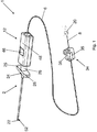
Fig. 1 shows a system according to a first embodiment of the invention; -
Fig. 2 shows the system inFig. 1 , in which some enlarged details are shown, with parts in transparency, and in which a component is partially disassembled; -
Fig. 3a shows a section of a component of the system inFig. 1 ; -
Fig. 3b shows some parts of a component of the system inFig. 1 ; -
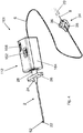
Fig. 4 shows a system according to a second embodiment of the invention; -
Fig. 5 shows the system inFig. 4 , in which some enlarged details are shown, with parts in transparency, and in which a component is partially disassembled; -
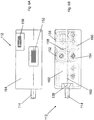
Fig. 6a shows a top view of one side of the component of the system inFig. 4 ; -
Fig. 6b shows a top view of another side of a component inFig. 4 , in which a part is shown in transparency; -
Fig. 7a schematically shows a portion of a type of needle;Fig. 7b schematically shows a portion of another type of needle; -
Fig. 8 schematically shows the operation of a sensor used in the system of the invention. - The same reference numerals in the figures identify the same elements or components.
- With reference to the Figures, a guiding system or guiding apparatus is shown, for guiding the insertion of a
needle 2 and of acatheter 6 for medical use in a biological tissue or compartment, the guiding system comprising: - the
needle 2, which is hollow and is provided with anend portion 52 having anedge 51 delimiting anopening 53 ofneedle 2,
said opening having a geometric center C,
and saidedge 51 comprising apointed end 22 ofneedle 2; - the
catheter 6 inserted into theneedle 2; - an
optical fiber 8 provided with at least oneoptical sensor 10 and inserted into thecatheter 6, - a
first locking device catheter 6 inside theneedle 2, - a first position in which end 32 of
catheter 6 is at the geometric center C of the opening ofneedle 2, and - a second position in which end 32 of
catheter 6 is at thepointed end 22 ofneedle 2, - In the embodiments shown, there is provided only one
optical fiber 8 with only oneoptical sensor 10, preferably of the optical fiber Bragg grating type. - The system of the invention is therefore provided with one end of
catheter 6 emerging fromneedle 2, so as to transfer the mechanical strains (compressions, expansions and bending) induced by the pressures due to the crossing of the biological tissues to theoptical sensor 10 integrated on theoptical fiber 8. Since such pressures are closely related with the elastic features of said tissues, theoptical fiber 8 provided with theoptical sensor 10 is able to provide useful information for a correct placement ofneedle 2 andcatheter 6 within the sought biological space. -
Needle 2 is of the medical type, for example of the type used for locoregional anesthesia, preferably for epidural anesthesia. Preferably, this type of needles is not of the steerable type. In particular, it is neither of the steerable type nor in manual or robotized manner. -
Needle 2 is provided with a lumen, being internally hollow.Needle 2 is substantially cylindrical and has anend portion 52, preferably curved, which comprises anedge 51 delimiting anopening 53.Opening 53 has a geometricalcenter C. Edge 51 comprises apointed end 22, ortip 22, which is the tip ofneedle 2. Thepointed end 22 is substantially the portion at the maximum distance frombase 24 ofneedle 2. Theend portion 52 is cut obliquely with respect to the longitudinal axis ofneedle 2, with a cutting angle other than 90°.Figs. 7a and 7b show two examples of needles which can be used in the present invention, respectively, in particular a portion of such needles. - The position of
catheter 6 with respect to the needle is such that theclosed end 32 ofcatheter 6 is between a first position P1, in which end 32 ofcatheter 6 is at, or aligned with, the geometric center C of the opening ofneedle 2, and a second position P2, in which end 32 ofcatheter 6 is at, or aligned with, thepointed end 22 ofneedle 2. - Typically,
edge 51, or contour, is elliptical. The first position P1 is at, or aligned with, center C of such an ellipse; the second position P2 is at, or aligned with, the end of the major axis of the ellipse, which corresponds to tip 22 of the needle. This ensures a physical contact ofcatheter 6 with the biological tissues during the insertion ofneedle 2 in the human body. - A
base 24 is provided at the other end ofneedle 2, opposite to tip 22, from which twolugs 26 branch off which form a single piece and which extend perpendicularly to the longitudinal axis ofneedle 2.Base 24 also comprises a fitting 28 of the luer type, and in particular of the female luer type. As is known, luer connectors are a standard of the fitting systems used to connect together components for medical use and typically consist of a barrel (female luer) made for example of transparent polypropylene (the color of which allows to identify the diameter of the needle) which locks by means of the connection to the plastic cone (male luer) of syringes. Other luer connection systems are referred to as luer lock, in which the female luer connector is screwed to the male luer connector. -
Catheter 6 is internally hollow and has anend portion 72, with a closed and preferably roundedend 32. Moreover, the end portion is provided with one or morelateral holes 5 which allow the release of a drug. - The
optical fiber 8 is inserted withincatheter 6 up to abutment with theclosed end 32 ofcatheter 6. Preferably, in order to improve the mechanical properties thereof, theoptical fiber 8 is coated around the cladding with polyamide or other biocompatible material suitable for clinical use. - The outer diameter of the
optical fiber 8, including any coating, is smaller than the inner diameter of the lumen ofcatheter 6 so that theoptical fiber 8 itself can be easily inserted/removed in/fromcatheter 6. Anoptical connector 20 is provided at the other end of theoptical fiber 8, that is, opposite to that in abutment withcatheter 6, for connecting theoptical fiber 8 to the optoelectronic interrogation unit (not shown). - At least one
optical sensor 10, preferably one sensor of the Bragg grating type, is integrated along the axis of theoptical fiber 8, at a certain distance from the end adapted to abut withcatheter 6, which acts as a deformation/pressure sensor. A brief description of the Bragg grating is given in the following description. The distance between theoptical sensor 10 and theend 32 ofcatheter 6, or the distance between the end of theoptical fiber 8 adapted to abut withend 32 ofcatheter 6, is less than or equal to 50 mm. Preferably, such a distance is of between 10 and 50 mm, more preferably between 10 and 30 mm, even more preferably between 10 and 20 mm, for example of about 15 mm. These distances allow an effective detection by theoptical sensor 10. - The
optical fiber 8 is fixed in position withincatheter 6 by alocking device 34. The blockingdevice 34 is preferably mounted in the vicinity of the end (opposite with respect to tip 22 of needle 2) ofcatheter 6 from which theoptical fiber 8 ending with theoptical connector 20 emerges. By way of example, the lockingdevice 34 is a cable clamp, comprising a base 35 in which a groove is formed foraccommodating catheter 6 with theoptical fiber 8 therein. A closinglever 36 is pivoted to base 35 which, when placed in a horizontal position with respect tobase 35, locks theoptical fiber 8 tocatheter 6 by means of a compression. -
Catheter 6 with theoptical fiber 8 withoptical sensor 10 therein is arranged insideneedle 2. For descriptive purposes, the assembly formed bycatheter 6 with theoptical fiber 8 with theoptical sensor 10 therein, in particular with Bragg grating, is also referred to assensorized catheter 6. The inner diameter of the lumen ofneedle 2 is larger than the outer diameter ofcatheter 6 in order to make the insertion and removal thereof easy. - The
sensorized catheter 6 is inserted intoneedle 2 and blocked in a specific position, defined above, by means of asuitable locking device needle 2. In general, the locking device - can be connected to a common
medical needle 2, preferably by means of a luer connection; - keeps the
sensorized catheter 6 blocked during the penetration ofneedle 2; - allows the
sensorized catheter 6 to slide insideneedle 2 when the penetration is interrupted. - Advantageously, the locking device according to the invention is also compact and lightweight, so as to be easy to handle.
- Exemplary and non-exclusive embodiments of locking devices are described hereinafter.
- According to a first embodiment (
Fig. 1-3 ), the lockingdevice 12 also allows a controlled movement ofcatheter 6 only when the operator actuates the moving means. In particular, locking means distinct from the moving means are provided. In order to allow the movement ofcatheter 6, a force must act oncatheter 6, provided by the actuation of the moving means, which must be greater than the locking force of the locking means. The lockingdevice 12 is configured so that such a force is greater than the forces to whichcatheter 6 is subject during the insertion ofneedle 2. - The locking
device 12 allows the fine sliding ofcatheter 6 and has a stroke of a few centimeters, for example but not exclusively ranging from 1 to 5 cm. - The locking
device 12 comprises: aninlet block 38 with afitting region 14, preferably a male luer fitting, aclamp gripper 42, ascrew 44 arranged within anut screw 46, abolt 50 and aseat 48 for such components, provided with an opening from which thenut screw 46 projects partially.Screw 44 comprises a parallelepiped-shaped portion arranged between two externally threaded cylindrical portions. Moreover, screw 44 is provided with a central channel in which thesensorized catheter 6 is inserted, which runs through the lockingdevice 12 from side to side. By means of the male luer fitting 14, of the interlocking or screwing type, the lockingdevice 12 can easily be connected toneedle 2 and in general to any standard medical needle. - The
inlet block 38 substantially serves to integrate, or mount, the lockingdevice 12 withneedle 2. - Once constrained to
needle 2, for example by insertion of fitting 28 in, or on, thefitting region 14, and once thesensorized catheter 6 has been inserted in thelocking device 12, the latter is able to both block thesensorized catheter 6 in position with respect toneedle 2, during the insertion of the needle, and to allow it to slide in both directions, once the needle has reached the desired biological tissue. - Locking means are used to block the
sensorized catheter 6, in particular theclamp gripper 42 capable of clamping, thereby constraining thesensorized catheter 6. The position of thesensorized catheter 6 is blocked due to theclamp gripper 42. In particular, an advance of thesensorized catheter 6 is not allowed without the rotation of thenut screw 46. In fact, a force is required, provided by the rotation of thenut screw 46, which must be greater than the clamping force of theclamp gripper 42 to translate thesensorized catheter 6 in a controlled manner. -
Gripper 42 is integrated inscrew 44, on which abolt 50 is in turn screwed. When by screwing,bolt 50 reaches the stroke end, it clamps the end part of theclamp gripper 42 up to close it so as to keep thesensorized catheter 6 blocked, so that it can move integrally withscrew 44. - The sliding of the
sensorized catheter 6 is achieved by means ofscrew 44 and thenut screw 46. This system is able to transform a rotary motion into a translation motion by means of a helical coupling obtained so that the rotation of one of the two elements (prevented from translating) causes the translation of the other (prevented from rotating). In the specific case, blocking the translation of thenut screw 46 and rotating thenut screw 46 causes a translation ofscrew 44. Constraining thesensorized catheter 6 to screw 44 by means of theclamp gripper 42, thereby locking the translation ofscrew 44, and rotating thenut screw 46, causes the translation of thesensorized catheter 6. The translation of thenut screw 46 is locked since it projects partially with respect to the opening ofseat 48. A recess is formed on the inner wall of the seat in which both thenut screw 46 and screw 44 are inserted. Therefore, by constrainingscrew 44 toseat 48 by interlocking, for example by means of the parallelepiped-shaped portion, screw 44 cannot rotate and the rotation of thenut screw 46 will cause translation ofscrew 44. Thesensorized catheter 6 then translates together withscrew 44, being constrained thereto by means of theclamp gripper 42. Each complete rotation of thenut screw 46 causes a translation of a few centimeters, for example but not exclusively ranging from 1 to 5 cm, ofscrew 44 and thereby of thesensorized catheter 6. By way of example only,seat 48 may be rectangular or cylindrical in shape. - In a second embodiment (
Fig. 4-6 ), thelocking device 112 also allows a controlled movement ofcatheter 6 only when the operator actuates the moving means. In particular, locking means distinct from the moving means are provided. The locking means act on the moving means so as to allow or prevent the actuation thereof by the operator. In order to lock and unlock the moving means, the locking means switch from a locking position to an unlocking position. When the locking means lock the actuation of the moving means,catheter 6 is firmly locked in position. In order to allow the movement ofcatheter 6, the moving means must be unlocked. - Once the moving means have been unlocked, preferably, the
locking device 112 allows a controlled and unlimited stroke of thesensorized catheter 6. Thelocking device 112 comprises:
aseat 164 provided with two openings; aninlet block 138 with afitting region 114, preferably a male luer fitting; twoadvance rollers advance roller 152 provides an advance control dial and partially protrudes from one of the openings ofseat 164; a rotary control lockingring nut 156 which partially protrudes fromseat 164; locking means, comprisingbrake 158, for locking theadvance roller 152 into position, the lockingring nut 156, which controlsbrake 158; and two elements, or alignment blocks 160, 162. - As for the
locking device 12 described above, theinlet block 138 has the function of allowing the integration of the blocking/slidingdevice 112 withneedle 2. Thesensorized catheter 6 is placed between the twoadvance rollers advance roller 152, thesensorized catheter 6 may move forward or backward inside the needle according to the rotation direction. Thealignment elements advance rollers sensorized catheter 6 inside the locking device, thereby aiding the insertion of thesensorized catheter 6 at the inlet, and aiding the exit ofneedle 2 towards the lumen at the outlet. Thealignment elements hole 165 inside which thesensorized catheter 6 passes.Hole 165 has a diameter slightly larger than that of thesensorized catheter 6 so as to allow it to slide. - The advancement of the
sensorized catheter 6 can be blocked by the lockingring nut 156, the rotation axis of which is decentralized. Therefore, a rotation of the lockingring nut 156 allows the latter to intercept or not interceptbrake 158, which presses against theadvance roller 152 so as to lock the rotation thereof. Theadvance roller 152 and the lockingring nut 156 slightly protrude fromseat 164 so that they can be operated and thus rotated from the outside with the fingers. The lockingring nut 156 has the function of keeping the twoadvance rollers needle 2, the lockingring nut 156 is active, i.e. the advance rollers are blocked, and thesensorized catheter 6 does not move with respect toneedle 2. When the needle is stationary, i.e. once the insertion ofneedle 2 has ended, in order to facilitate the advance of thesensorized catheter 6, the lockingring nut 6 is deactivated by rotating it by 180°, so that theadvance rollers sensorized catheter 6. - The
locking devices - Both locking
devices - keep the
sensorized catheter 6 constrained, for example at a point, while a force is applied on the end due to the pressure exerted by the biological tissues crossed during the insertion ofneedle 2. In fact, the resistance of the tissues in contact with thesensorized catheter 6, particularly withend 32 during the advance step thereof, is directly proportional to the strain undergone by the optical fiber Bragg grating placed inside the catheter; - allow the
sensorized catheter 6 to exit from the tip ofneedle 2 in a controlled and measurable manner so as to slide it inside the human body for carrying out measurements of deformation and bucking in situ using the optical fiber sensor (i.e. the Bragg grating). - In general, when a blocking and moving device is used, it is preferably provided with indication means, such as a graduated scale, which allow the position of the catheter to be indicated, in particular which allow the advancement extent of the catheter with respect to the needle tip to be indicated.
- According to an embodiment (not disclosed), a locking device is provided which is configured exclusively for locking, by means of locking means, the position of the sensorized catheter up to reaching the desired biological tissue, and for unlocking the catheter once such a tissue has been reached.
- This locking device has a luer fitting for constraining the needle, and catheter completely crosses the locking device. Preferably, a groove or a channel is provided where the catheter is accommodated. Locking means are provided, such as a button, which can be activated by the operator. The locking means are configured to act on the catheter so as to lock the position thereof. Preferably, a mechanism is provided which keeps the locking means in the locked position and which allows the catheter to be unlocked.
- The description of the above locking devices should not be deemed as limiting. In fact, other locking or locking and moving devices may also be used without departing from the scope of the present invention.
- After providing an exemplary description of the system according to the invention, an example of the operation thereof is now provided with reference to the execution of an epidural anesthesia.
- In this case, pressure is an important parameter of differentiation. Indeed, the loss of resistance technique, which is the most common procedure currently used, is based on the perception of density variation between the yellow ligament and the epidural space. In particular, the continuous pressure monitoring according to the invention allows to achieve a high specificity and sensitivity in the identification of the epidural space. In addition to locating the epidural space and thereby properly placing the needle, the
system catheter 6 in the epidural space. In fact, during the sliding and placement ofcatheter 6 in the epidural space, thanks to theoptical fiber 8 provided withoptical sensor 10, which moves integrally withcatheter 6, any deformations due to the bending ofcatheter 6 itself can be detected, which are associated with kinking phenomena, i.e. whencatheter 6 fits within spaces involving high bending radii of the catheter itself. Therefore, the system of the invention allows not only to locate the epidural space during the advance ofneedle 2, but also to monitor the proper placement ofcatheter 6 in the epidural space, preventingcatheter 6 itself from ending into intervertebral foramina, thereby causing the failure of the epidural anesthesia. - As already described above, in the system of the invention,
catheter 6 is sensorized by the insertion of anoptical fiber 8 in the lumen thereof, including at least oneoptical sensor 10, preferably one Bragg grating. - The Bragg grating, also known as "Fiber Bragg Grating" (FBG), can be easily manufactured and integrated within the optical fiber using a UV lithographic process. With particular reference to
Fig. 8 , the FBG is an optical fiber segment characterized by a periodic modulation of the refractive index along the axis of the fiber core. Such a grating behaves like a band-pass filter in reflection and a bandstop filter in transmission. The reflection peak is centered at the Bragg wavelength given by λB =2 neff Λ where neff is the effective refraction index of the medium, Λ is the grating period. Since a longitudinal deformation, or strain, modulates both n and Λ, the Bragg wavelength undergoes a shift following a perturbation of the environment outside the fiber. Therefore, in the system of the invention, as thesensorized catheter 6 is inserted into the human body, theoptical sensor 10 undergoes a stretching or a buckling depending on the elasticity of the tissues which are crossed. The compressions and expansions of theoptical sensor 10, i.e. of the FBG, involve a shift of the Bragg wavelength towards shorter or longer wavelengths, respectively. When thesensorized catheter 6 and thus the FBG bend (in particular for bending radii for which the condition of light confinement is no longer satisfied by total internal reflection), in addition to a shift of the Bragg wavelength, there is also a strong reduction in the intensity of the reflected peak due to light escaping from the fiber core and therefore to propagation losses. This phenomenon allows to monitor any kinking of the catheter during the steps of placing it in the biological spaces. - The interrogation of the
optical sensor 10 takes place through an optoelectronic interrogation unit directly connected to the optical fiber Bragg grating by means of theoptical connector 20. - It is preferred that the interrogation units substantially comprises a light source, a spectrophotometer which measures the optical signal reflected by the FBG, and an directional optical fiber coupler for the interrogation in reflection of the
optical sensor 10. The interrogation unit then processes the collected data, monitors the temporal variations of the spectrum reflected by the Bragg grating (such as a shift in the wavelength and intensity variations associated with the reflected peak), and associates them with pressure measurements. In practice, the interrogation unit contains all the devices and electronic components capable of processing the data acquired. The data acquired and in particular the trends in real time of the intensity and wavelength of the reflected Bragg peak are sent to data processing means adapted to process and display said data. For example, a device may be provided such as a PC, tablet, etc., the display of which displays information which can be read in real time by the operator. - The system as a whole works as follows: the
optical fiber 8 withoptical sensor 10 is optically connected by means of anoptical connector 20 to the interrogation unit. A light signal generated by the source is coupled to theoptical fiber 8 incorporated intocatheter 6 in turn inserted intoneedle 2 and travels therein, thus reaching the Bragg gratingoptical sensor 10. The Bragg grating reflects a light share at a specific wavelength which goes back to the interrogation unit through the same fiber. Therefore, whenneedle 2 and thesensorized catheter 6 inserted therein cross different types of tissues, theoptical sensor 10 detects and transmits an optical signal to the interrogation unit related to the pressure changes to which it is subject. In fact, theoptical fiber sensor 10 is designed so that any specific variation of its geometric and physical properties (for example due to strain and buckling) matches a change of the reflected light signal. The interrogation unit includes a detection module capable of measuring the spectrum reflected by the sensor and processing the data acquired, possibly by correlating the spectral changes to pressure changes. By monitoring these changes, the system is therefore able to provide information about the position ofneedle 2 when passing from one tissue to another, and about the number of tissues crossed during the insertion, bends of the catheter, etc. - The system of the invention allows to place the needle and thus the
sensorized catheter 6 in the biological space of interest. The system of the invention is connected to the optoelectronic interrogation unit by means of theoptical connector 20. The operator, such as the physician, insertsneedle 2 into the patient's body by preferably applying a continuous pressure onneedle 2, and then on thesensorized catheter 6 which is constrained thereto by means of the locking device, thus favoring the penetration ofneedle 2 through the various tissues. Depending on the composition (in terms of density, elasticity, etc.) of the tissues crossed, the FBGoptical fiber sensor 10 integrated intocatheter 6 undergoes different compressions which directly convert into variations of the reflected optical signal. These variations are measured by the interrogation unit to which thesensorized catheter 6 is constrained and displayed on the device display (PC, tablet, etc.) which interfaces with the interrogation unit. When the operator sees a combination of measured parameters (such as sudden variations in the reflection peak wavelength) compatible with a relaxation ofcatheter 6 inside the human body, shown on the display, he/she will stop the penetration and will check that the sought space has been reached, possibly using the sliding system. In fact, at this point, thesensorized catheter 6 can be slid intoneedle 2 and inserted in the biological spaces, checking the correct placement (thus avoiding kinking phenomena of the catheter) by monitoring the stability of the optical signal reflected on the display (in terms of wavelength and/or reflection peak intensity). Finally, oncecatheter 6 has been properly placed, theoptical fiber 8 can be extracted fromcatheter 6 by acting ondevice 34, so as to allow the administration of any drugs. - Alternatively, if the physician deems it necessary, the catheter may be extracted from the needle and a drug may be directly administered through the needle.
wherein the optical fiber is in abutment with the end of the catheter,
wherein the optical sensor is spaced from said end of the catheter by a distance less than or equal to 50 mm,
wherein the position of the catheter with respect to the needle is such that said end of the catheter is between
wherein the
wherein the
wherein the position of
Claims (14)
- A guiding system (1, 101) for guiding the insertion of a needle (2) and a catheter (6) for medical use in a biological tissue or compartment, the guiding system (1, 101) comprising:- the needle (2), which is hollow and is provided with an end portion (52) having an edge (51) delimiting an opening (53) of the needle (2),
said opening having a geometric center (C),
and said edge (51) comprising a pointed end (22) of the needle (2);- the catheter (6) inserted into the needle (2);- an optical fiber (8) provided with at least one optical sensor (10) and inserted into the catheter (6),- a first locking device (12, 112) for firmly blocking the catheter (6) inside the needle (2),wherein the catheter (6) is provided with an end (32) proximal to the pointed end (22),
wherein the optical fiber (8) is in abutment with the end (32) of the catheter (6), wherein the optical sensor (10) is spaced from said end (32) of the catheter (6) by a distance less than or equal to 50 mm,
wherein the position of the catheter (6) with respect to the needle (2) is such that said end (32) of the catheter (6) is betweena first position in which the end (32) of the catheter (6) is at the geometric center (C) of the opening of the needle (2), anda second position in which the end (32) of the catheter (6) is at the pointed end (22) of the needle (2),whereby any deformations of the catheter (6) are detected by the optical fiber (8) and the optical sensor (10) during the insertion of the needle (2);
wherein the first locking device (12, 112) comprises locking means for locking the catheter (6), and adjustment means adapted to adjust the position of the catheter (6) in a controlled manner with respect to the needle (2), said adjustment means being distinct from the locking means. - A system according to claim 1, comprising only one optical fiber (8).
- A system according to claim 2, wherein the optical fiber (8) is provided with only one optical sensor (10), preferably of the fiber Bragg grating-type.
- A system according to any one of the preceding claims, wherein the optical sensor (10) is spaced from said end (32) of the catheter (6) by a distance of between 10 and 50 mm.
- A system according to claim 4, wherein the optical sensor (10) is spaced from said end (32) of the catheter (6) by a distance of between 10 and 30 mm, preferably between 10 and 20 mm.
- A system according to any one of the preceding claims, wherein the optical sensor (10) has an axial length of between 1 and 15 mm, and wherein the longitudinal axis of the optical sensor (10) is parallel to the longitudinal axis of the optical fiber (8).
- A system according to any one of the preceding claims, wherein the needle (2) is for locoregional anesthesia, particularly for epidural anesthesia.
- A system according to any one of the preceding claims, wherein said end (32) of the catheter (6) is closed and wherein said end portion (52) of the catheter (6) is provided with at least one lateral opening (5).
- A system according to any one of the preceding claims, wherein said locking means are configured to act directly on the catheter (6) to lock it in position, or wherein said blocking means are configured to act on the adjustment means to lock the catheter (6) in position.
- A system according to any one of the preceding claims, wherein said adjustment means comprise an element (46, 152) adapted to rotate so that a rotation thereof causes a translation of the catheter (6).
- A system according to any one of the preceding claims, comprising a second locking device (34) adapted to lock the optical fiber (8) in place inside the catheter (6).
- A system according to any one of the preceding claims, comprising an optoelectronic interrogation unit adapted to be connected to the optical fiber (8) by means of a connector (20) to receive data from said optical sensor (10).
- A system according to claim 12, wherein there are provided data processing means adapted to process and display said data.
- A kit for assembling a system according to any one of the preceding claims, comprising said needle (2), said catheter (6), and said optical fiber (8) provided with said sensor (10).
Priority Applications (4)
| Application Number | Priority Date | Filing Date | Title |
|---|---|---|---|
| PL16812822T PL3361946T3 (en) | 2015-10-16 | 2016-10-17 | Guiding system for the insertion of a medical needle |
| RS20191373A RS59590B1 (en) | 2015-10-16 | 2016-10-17 | Guiding system for the insertion of a medical needle |
| SM20190640T SMT201900640T1 (en) | 2015-10-16 | 2016-10-17 | Guiding system for the insertion of a medical needle |
| HRP20191950TT HRP20191950T1 (en) | 2015-10-16 | 2016-10-17 | LEADING MEDICAL NEEDLE INSERT SYSTEM |
Applications Claiming Priority (2)
| Application Number | Priority Date | Filing Date | Title |
|---|---|---|---|
| ITUB2015A005218A ITUB20155218A1 (en) | 2015-10-16 | 2015-10-16 | SYSTEM FOR GUIDING MEDICAL DEVICES |
| PCT/IB2016/056212 WO2017064682A1 (en) | 2015-10-16 | 2016-10-17 | Guiding system for the insertion of a medical needle |
Publications (2)
| Publication Number | Publication Date |
|---|---|
| EP3361946A1 EP3361946A1 (en) | 2018-08-22 |
| EP3361946B1 true EP3361946B1 (en) | 2019-07-31 |
Family
ID=55237868
Family Applications (1)
| Application Number | Title | Priority Date | Filing Date |
|---|---|---|---|
| EP16812822.1A Active EP3361946B1 (en) | 2015-10-16 | 2016-10-17 | Guiding system for the insertion of a medical needle |
Country Status (14)
| Country | Link |
|---|---|
| US (1) | US10588657B2 (en) |
| EP (1) | EP3361946B1 (en) |
| CN (1) | CN108471985B (en) |
| CA (1) | CA3039648C (en) |
| DK (1) | DK3361946T3 (en) |
| ES (1) | ES2751704T3 (en) |
| HR (1) | HRP20191950T1 (en) |
| HU (1) | HUE045983T2 (en) |
| IT (1) | ITUB20155218A1 (en) |
| PL (1) | PL3361946T3 (en) |
| PT (1) | PT3361946T (en) |
| RS (1) | RS59590B1 (en) |
| SM (1) | SMT201900640T1 (en) |
| WO (1) | WO2017064682A1 (en) |
Families Citing this family (35)
| Publication number | Priority date | Publication date | Assignee | Title |
|---|---|---|---|---|
| US12140487B2 (en) | 2017-04-07 | 2024-11-12 | Bard Access Systems, Inc. | Optical fiber-based medical device tracking and monitoring system |
| CN109231152B (en) * | 2018-09-30 | 2020-06-16 | 重庆大学 | Micro-clamps for measuring clamping force and jaw displacement using a fiber-optic Fabry-Perot interferometer |
| CA3150788A1 (en) | 2019-08-12 | 2021-02-18 | Bard Access Systems, Inc. | Shape-sensing systems and methods for medical devices |
| WO2021108697A1 (en) | 2019-11-25 | 2021-06-03 | Bard Access Systems, Inc. | Optical tip-tracking systems and methods thereof |
| CN112826480B (en) | 2019-11-25 | 2025-04-18 | 巴德阿克塞斯系统股份有限公司 | Shape sensing system with filter and method thereof |
| CN113318324B (en) | 2020-02-28 | 2026-05-12 | 巴德阿克塞斯系统股份有限公司 | Catheter with optical shape sensing capability |
| WO2021173861A1 (en) | 2020-02-28 | 2021-09-02 | Bard Access Systems, Inc. | Optical connection systems and methods thereof |
| WO2021178578A1 (en) | 2020-03-03 | 2021-09-10 | Bard Access Systems, Inc. | System and method for optic shape sensing and electrical signal conduction |
| US11931179B2 (en) | 2020-03-30 | 2024-03-19 | Bard Access Systems, Inc. | Optical and electrical diagnostic systems and methods thereof |
| CN113842536B (en) | 2020-06-26 | 2026-03-17 | 巴德阿克塞斯系统股份有限公司 | Misalignment detection system |
| CN113926050B (en) * | 2020-06-29 | 2026-04-14 | 巴德阿克塞斯系统股份有限公司 | Automatic dimensional reference system for optical fibers |
| CN216317552U (en) * | 2020-07-10 | 2022-04-19 | 巴德阿克塞斯系统股份有限公司 | Medical device system for detecting damage and potential damage to optical fiber technology of medical devices |
| EP4188212A1 (en) | 2020-08-03 | 2023-06-07 | Bard Access Systems, Inc. | Bragg grated fiber optic fluctuation sensing and monitoring system |
| WO2022067096A1 (en) | 2020-09-25 | 2022-03-31 | Bard Access Systems, Inc. | Fiber optics oximetry system for detection and confirmation |
| CN114343843A (en) | 2020-10-13 | 2022-04-15 | 巴德阿克塞斯系统股份有限公司 | Fiber Optic-Enabled Deployable Medical Devices for Monitoring, Evaluating, and Collecting Deployment Information |
| US11899249B2 (en) | 2020-10-13 | 2024-02-13 | Bard Access Systems, Inc. | Disinfecting covers for functional connectors of medical devices and methods thereof |
| WO2022104537A1 (en) * | 2020-11-17 | 2022-05-27 | 苏州市立普医疗科技有限公司 | Puncture needle seat |
| CN112315556A (en) * | 2020-11-17 | 2021-02-05 | 苏州市立普医疗科技有限公司 | A puncture needle holder |
| CN216558785U (en) | 2020-11-18 | 2022-05-17 | 巴德阿克塞斯系统股份有限公司 | Fiber optic stylet holder |
| WO2022115624A1 (en) | 2020-11-24 | 2022-06-02 | Bard Access Systems, Inc. | Steerable fiber optic shape sensing enabled elongated medical instrument |
| WO2022150411A1 (en) | 2021-01-06 | 2022-07-14 | Bard Access Systems, Inc. | Needle guidance using fiber optic shape sensing |
| EP4280995A1 (en) | 2021-01-26 | 2023-11-29 | Bard Access Systems, Inc. | Fiber optic shape sensing system associated with port placement |
| US12490937B2 (en) * | 2021-05-18 | 2025-12-09 | Bard Access Systems, Inc. | Anatomical oscillation and fluctuation sensing and confirmation system |
| CN115813547A (en) | 2021-09-16 | 2023-03-21 | 巴德阿克塞斯系统股份有限公司 | Methods of connecting components and performing medical procedures |
| WO2023076143A1 (en) | 2021-10-25 | 2023-05-04 | Bard Access Systems, Inc. | Reference plane for medical device placement |
| US12318149B2 (en) | 2022-03-08 | 2025-06-03 | Bard Access Systems, Inc. | Medical shape sensing devices and systems |
| US12426956B2 (en) | 2022-03-16 | 2025-09-30 | Bard Access Systems, Inc. | Medical system and method for monitoring medical device insertion and illumination patterns |
| US12089815B2 (en) | 2022-03-17 | 2024-09-17 | Bard Access Systems, Inc. | Fiber optic medical systems and devices with atraumatic tip |
| US12605116B2 (en) | 2022-04-11 | 2026-04-21 | Bard Access Systems, Inc. | Fiber optic medical systems and devices with electrical tip |
| US20230346482A1 (en) * | 2022-04-27 | 2023-11-02 | Bard Access Systems, Inc. | Conductor Incorporated Fiber Enabled Medical Systems |
| US12575893B2 (en) | 2022-06-24 | 2026-03-17 | Bard Access Systems, Inc. | Shape sensing fiber optic tip protection systems and devices |
| US12343117B2 (en) | 2022-06-28 | 2025-07-01 | Bard Access Systems, Inc. | Fiber optic medical systems and methods for identifying blood vessels |
| US12349984B2 (en) | 2022-06-29 | 2025-07-08 | Bard Access Systems, Inc. | System, method, and apparatus for improved confirm of an anatomical position of a medical instrument |
| US12564340B2 (en) | 2022-07-12 | 2026-03-03 | Bard Access Systems, Inc. | Eccentric single-core fiber-optic enabled medical device |
| CN115486909B (en) * | 2022-09-22 | 2025-10-10 | 浙江伽奈维医疗科技有限公司 | A composite optical navigation puncture positioning needle and needle tip posture detection method |
Family Cites Families (24)
| Publication number | Priority date | Publication date | Assignee | Title |
|---|---|---|---|---|
| US5356381A (en) * | 1990-03-01 | 1994-10-18 | Ensminger William D | Implantable access devices |
| US5180365A (en) * | 1990-03-01 | 1993-01-19 | Ensminger William D | Implantable infusion device |
| US5251276A (en) * | 1992-07-16 | 1993-10-05 | Corning Incorporated | Environmentally robust fiber optic coupler and method |
| US5713858A (en) * | 1995-04-28 | 1998-02-03 | Medtronic, Inc. | Permanently implantable guiding catheter |
| US6993376B2 (en) * | 2002-01-28 | 2006-01-31 | Testardi Louis R | Radiation measurement within the human body |
| EP1653896B1 (en) * | 2003-07-28 | 2013-04-03 | Synergetics, Inc. | Coaxial illuminated laser endoscopic probe |
| JP2005225749A (en) * | 2004-01-14 | 2005-08-25 | Shin Etsu Chem Co Ltd | Optical fiber preform stretching method and apparatus |
| WO2006086700A2 (en) * | 2005-02-10 | 2006-08-17 | Lightlab Imaging, Inc. | Optical coherence tomography apparatus and methods |
| SE0501077L (en) * | 2005-05-12 | 2006-11-13 | Spectracure Ab | Device for photodynamic diagnosis or treatment |
| US20070265503A1 (en) * | 2006-03-22 | 2007-11-15 | Hansen Medical, Inc. | Fiber optic instrument sensing system |
| EP2037795A2 (en) * | 2006-07-10 | 2009-03-25 | Boston Scientific Limited | Optical spectroscopic injection needle |
| US8050523B2 (en) * | 2007-04-20 | 2011-11-01 | Koninklijke Philips Electronics N.V. | Optical fiber shape sensing systems |
| US8347738B2 (en) * | 2007-05-09 | 2013-01-08 | The Board Of Trustees Of The Leland Stanford Junior University | Sensors and control for an interventional catheter |
| US20130165945A9 (en) * | 2007-08-14 | 2013-06-27 | Hansen Medical, Inc. | Methods and devices for controlling a shapeable instrument |
| US10238370B2 (en) * | 2009-09-18 | 2019-03-26 | Intelligent Fiber Optic Systems, Inc. | Steerable shape sensing biopsy needle |
| RU2589625C2 (en) * | 2010-02-09 | 2016-07-10 | Конинклейке Филипс Электроникс Н.В. | Device, system and method for imaging and treatment using optical determination of position |
| US8460236B2 (en) * | 2010-06-24 | 2013-06-11 | Hansen Medical, Inc. | Fiber optic instrument sensing system |
| US8672837B2 (en) * | 2010-06-24 | 2014-03-18 | Hansen Medical, Inc. | Methods and devices for controlling a shapeable medical device |
| CA3065357C (en) * | 2011-05-18 | 2023-04-25 | Solodex Llc | Continuous anesthesia nerve conduction apparatus, system and method |
| US20140031677A1 (en) * | 2012-01-20 | 2014-01-30 | Physical Sciences, Inc. | Apparatus and Method for Aiding Needle Biopsies |
| KR102356881B1 (en) * | 2013-08-15 | 2022-02-03 | 인튜어티브 서지컬 오퍼레이션즈 인코포레이티드 | Graphical user interface for catheter positioning and insertion |
| US20160256101A1 (en) * | 2013-10-14 | 2016-09-08 | Avraham Aharoni | Device and System Device and System for Imaging Veins |
| US12140487B2 (en) * | 2017-04-07 | 2024-11-12 | Bard Access Systems, Inc. | Optical fiber-based medical device tracking and monitoring system |
| CN110944591B (en) * | 2017-08-02 | 2023-05-12 | 圣犹达医疗用品国际控股有限公司 | Optical force sensing catheter system |
-
2015
- 2015-10-16 IT ITUB2015A005218A patent/ITUB20155218A1/en unknown
-
2016
- 2016-10-17 US US15/767,737 patent/US10588657B2/en active Active
- 2016-10-17 CA CA3039648A patent/CA3039648C/en active Active
- 2016-10-17 CN CN201680074700.2A patent/CN108471985B/en active Active
- 2016-10-17 PL PL16812822T patent/PL3361946T3/en unknown
- 2016-10-17 HR HRP20191950TT patent/HRP20191950T1/en unknown
- 2016-10-17 EP EP16812822.1A patent/EP3361946B1/en active Active
- 2016-10-17 RS RS20191373A patent/RS59590B1/en unknown
- 2016-10-17 HU HUE16812822A patent/HUE045983T2/en unknown
- 2016-10-17 DK DK16812822T patent/DK3361946T3/en active
- 2016-10-17 ES ES16812822T patent/ES2751704T3/en active Active
- 2016-10-17 WO PCT/IB2016/056212 patent/WO2017064682A1/en not_active Ceased
- 2016-10-17 PT PT168128221T patent/PT3361946T/en unknown
- 2016-10-17 SM SM20190640T patent/SMT201900640T1/en unknown
Non-Patent Citations (1)
| Title |
|---|
| None * |
Also Published As
| Publication number | Publication date |
|---|---|
| US10588657B2 (en) | 2020-03-17 |
| EP3361946A1 (en) | 2018-08-22 |
| DK3361946T3 (en) | 2019-10-28 |
| ITUB20155218A1 (en) | 2017-04-16 |
| HRP20191950T1 (en) | 2020-01-24 |
| PL3361946T3 (en) | 2020-03-31 |
| ES2751704T3 (en) | 2020-04-01 |
| WO2017064682A1 (en) | 2017-04-20 |
| RS59590B1 (en) | 2019-12-31 |
| US20180289390A1 (en) | 2018-10-11 |
| PT3361946T (en) | 2019-11-05 |
| CN108471985B (en) | 2021-03-12 |
| CA3039648C (en) | 2023-12-12 |
| CA3039648A1 (en) | 2017-04-20 |
| CN108471985A (en) | 2018-08-31 |
| HUE045983T2 (en) | 2020-01-28 |
| SMT201900640T1 (en) | 2020-01-14 |
Similar Documents
| Publication | Publication Date | Title |
|---|---|---|
| US10588657B2 (en) | Guiding system for the insertion of a medical needle | |
| US20160256101A1 (en) | Device and System Device and System for Imaging Veins | |
| CN108135530B (en) | A hub for device navigation utilizing optical shape-sensing guidewires | |
| Carotenuto et al. | Optical guidance systems for epidural space identification | |
| US20180078317A1 (en) | Systems, methods and devices for tracking and calibration of flexible instruments | |
| JP7346393B2 (en) | Optical connection devices and methods | |
| EP1874378B1 (en) | Cannula inserting system having tissue analysis means | |
| EP3435910B1 (en) | Cannula locator device | |
| JP2015512711A (en) | Medical needle | |
| DE202014100938U1 (en) | Pressure measuring device | |
| EP3200715A1 (en) | Triggering with optical shape sensing fiber | |
| WO2011005954A2 (en) | A system and method for visualizing needle entry into a body | |
| WO2014144307A2 (en) | Probe assembly and disposable cover particularly for use in endoscope applications of low coherence interferometry | |
| Desjardins et al. | Epidural needle with embedded optical fibers for spectroscopic differentiation of tissue: ex vivo feasibility study | |
| WO2008131303A3 (en) | Optical fiber shape sensing systems | |
| Wang et al. | Enhancing epidural needle guidance using a polarization‐sensitive optical coherence tomography probe with convolutional neural networks | |
| US10299826B2 (en) | Needle for invasive medical use and needle assembly | |
| WO2009111579A2 (en) | Spectrometric methods and apparatus | |
| Desjardins et al. | Needle stylet with integrated optical fibers for spectroscopic contrast during peripheral nerve blocks | |
| Beisenova et al. | Fiber Bragg grating sensor-based optical guidance system for epidural catheter | |
| Mendez | Fiber Bragg grating sensors for biomedical applications | |
| Kesner et al. | Multifiber optical bend sensor to aid colonoscope navigation | |
| Rinehart | Design and Evaluation of a Fiber Optic Shape Tracker for Use as a Navigational Aid in Endovascular Guidewires and Catheters |
Legal Events
| Date | Code | Title | Description |
|---|---|---|---|
| STAA | Information on the status of an ep patent application or granted ep patent |
Free format text: STATUS: UNKNOWN |
|
| STAA | Information on the status of an ep patent application or granted ep patent |
Free format text: STATUS: THE INTERNATIONAL PUBLICATION HAS BEEN MADE |
|
| PUAI | Public reference made under article 153(3) epc to a published international application that has entered the european phase |
Free format text: ORIGINAL CODE: 0009012 |
|
| STAA | Information on the status of an ep patent application or granted ep patent |
Free format text: STATUS: REQUEST FOR EXAMINATION WAS MADE |
|
| 17P | Request for examination filed |
Effective date: 20180516 |
|
| AK | Designated contracting states |
Kind code of ref document: A1 Designated state(s): AL AT BE BG CH CY CZ DE DK EE ES FI FR GB GR HR HU IE IS IT LI LT LU LV MC MK MT NL NO PL PT RO RS SE SI SK SM TR |
|
| AX | Request for extension of the european patent |
Extension state: BA ME |
|
| DAV | Request for validation of the european patent (deleted) | ||
| DAX | Request for extension of the european patent (deleted) | ||
| REG | Reference to a national code |
Ref country code: DE Ref legal event code: R079 Ref document number: 602016017886 Country of ref document: DE Free format text: PREVIOUS MAIN CLASS: A61B0005060000 Ipc: A61B0017340000 |
|
| GRAP | Despatch of communication of intention to grant a patent |
Free format text: ORIGINAL CODE: EPIDOSNIGR1 |
|
| STAA | Information on the status of an ep patent application or granted ep patent |
Free format text: STATUS: GRANT OF PATENT IS INTENDED |
|
| RIC1 | Information provided on ipc code assigned before grant |
Ipc: A61B 5/06 20060101ALI20190204BHEP Ipc: A61B 17/34 20060101AFI20190204BHEP Ipc: A61M 25/01 20060101ALI20190204BHEP Ipc: A61B 17/00 20060101ALI20190204BHEP Ipc: G02B 6/02 20060101ALI20190204BHEP Ipc: A61B 34/20 20160101ALI20190204BHEP |
|
| INTG | Intention to grant announced |
Effective date: 20190307 |
|
| GRAS | Grant fee paid |
Free format text: ORIGINAL CODE: EPIDOSNIGR3 |
|
| GRAA | (expected) grant |
Free format text: ORIGINAL CODE: 0009210 |
|
| STAA | Information on the status of an ep patent application or granted ep patent |
Free format text: STATUS: THE PATENT HAS BEEN GRANTED |
|
| AK | Designated contracting states |
Kind code of ref document: B1 Designated state(s): AL AT BE BG CH CY CZ DE DK EE ES FI FR GB GR HR HU IE IS IT LI LT LU LV MC MK MT NL NO PL PT RO RS SE SI SK SM TR |
|
| REG | Reference to a national code |
Ref country code: CH Ref legal event code: EP Ref country code: GB Ref legal event code: FG4D |
|
| REG | Reference to a national code |
Ref country code: DE Ref legal event code: R096 Ref document number: 602016017886 Country of ref document: DE |
|
| REG | Reference to a national code |
Ref country code: AT Ref legal event code: REF Ref document number: 1160102 Country of ref document: AT Kind code of ref document: T Effective date: 20190815 |
|
| REG | Reference to a national code |
Ref country code: IE Ref legal event code: FG4D |
|
| REG | Reference to a national code |
Ref country code: DK Ref legal event code: T3 Effective date: 20191025 Ref country code: HR Ref legal event code: TUEP Ref document number: P20191950T Country of ref document: HR |
|
| REG | Reference to a national code |
Ref country code: RO Ref legal event code: EPE |
|
| REG | Reference to a national code |
Ref country code: PT Ref legal event code: SC4A Ref document number: 3361946 Country of ref document: PT Date of ref document: 20191105 Kind code of ref document: T Free format text: AVAILABILITY OF NATIONAL TRANSLATION Effective date: 20191028 |
|
| REG | Reference to a national code |
Ref country code: SE Ref legal event code: TRGR |
|
| REG | Reference to a national code |
Ref country code: CH Ref legal event code: NV Representative=s name: IPWAY SAGL, CH |
|
| REG | Reference to a national code |
Ref country code: NL Ref legal event code: FP |
|
| REG | Reference to a national code |
Ref country code: LT Ref legal event code: MG4D |
|
| REG | Reference to a national code |
Ref country code: NO Ref legal event code: T2 Effective date: 20190731 |
|
| REG | Reference to a national code |
Ref country code: SK Ref legal event code: T3 Ref document number: E 32483 Country of ref document: SK |
|
| REG | Reference to a national code |
Ref country code: HR Ref legal event code: ODRP Ref document number: P20191950T Country of ref document: HR Payment date: 20191028 Year of fee payment: 4 |
|
| REG | Reference to a national code |
Ref country code: HR Ref legal event code: T1PR Ref document number: P20191950 Country of ref document: HR |
|
| REG | Reference to a national code |
Ref country code: HU Ref legal event code: AG4A Ref document number: E045983 Country of ref document: HU |
|
| PG25 | Lapsed in a contracting state [announced via postgrant information from national office to epo] |
Ref country code: LT Free format text: LAPSE BECAUSE OF FAILURE TO SUBMIT A TRANSLATION OF THE DESCRIPTION OR TO PAY THE FEE WITHIN THE PRESCRIBED TIME-LIMIT Effective date: 20190731 |
|
| PG25 | Lapsed in a contracting state [announced via postgrant information from national office to epo] |
Ref country code: IS Free format text: LAPSE BECAUSE OF FAILURE TO SUBMIT A TRANSLATION OF THE DESCRIPTION OR TO PAY THE FEE WITHIN THE PRESCRIBED TIME-LIMIT Effective date: 20191130 Ref country code: AL Free format text: LAPSE BECAUSE OF FAILURE TO SUBMIT A TRANSLATION OF THE DESCRIPTION OR TO PAY THE FEE WITHIN THE PRESCRIBED TIME-LIMIT Effective date: 20190731 Ref country code: LV Free format text: LAPSE BECAUSE OF FAILURE TO SUBMIT A TRANSLATION OF THE DESCRIPTION OR TO PAY THE FEE WITHIN THE PRESCRIBED TIME-LIMIT Effective date: 20190731 |
|
| REG | Reference to a national code |
Ref country code: GR Ref legal event code: EP Ref document number: 20190403281 Country of ref document: GR Effective date: 20200213 |
|
| REG | Reference to a national code |
Ref country code: ES Ref legal event code: FG2A Ref document number: 2751704 Country of ref document: ES Kind code of ref document: T3 Effective date: 20200401 |
|
| REG | Reference to a national code |
Ref country code: CH Ref legal event code: PCAR Free format text: NEW ADDRESS: VIA FRANCESCO SOMAINI 9, 6900 LUGANO (CH) |
|
| PG25 | Lapsed in a contracting state [announced via postgrant information from national office to epo] |
Ref country code: EE Free format text: LAPSE BECAUSE OF FAILURE TO SUBMIT A TRANSLATION OF THE DESCRIPTION OR TO PAY THE FEE WITHIN THE PRESCRIBED TIME-LIMIT Effective date: 20190731 |
|
| PG25 | Lapsed in a contracting state [announced via postgrant information from national office to epo] |
Ref country code: IS Free format text: LAPSE BECAUSE OF FAILURE TO SUBMIT A TRANSLATION OF THE DESCRIPTION OR TO PAY THE FEE WITHIN THE PRESCRIBED TIME-LIMIT Effective date: 20200224 Ref country code: MC Free format text: LAPSE BECAUSE OF FAILURE TO SUBMIT A TRANSLATION OF THE DESCRIPTION OR TO PAY THE FEE WITHIN THE PRESCRIBED TIME-LIMIT Effective date: 20190731 |
|
| REG | Reference to a national code |
Ref country code: DE Ref legal event code: R097 Ref document number: 602016017886 Country of ref document: DE |
|
| PLBE | No opposition filed within time limit |
Free format text: ORIGINAL CODE: 0009261 |
|
| STAA | Information on the status of an ep patent application or granted ep patent |
Free format text: STATUS: NO OPPOSITION FILED WITHIN TIME LIMIT |
|
| PG2D | Information on lapse in contracting state deleted |
Ref country code: IS |
|
| PG25 | Lapsed in a contracting state [announced via postgrant information from national office to epo] |
Ref country code: LU Free format text: LAPSE BECAUSE OF NON-PAYMENT OF DUE FEES Effective date: 20191017 Ref country code: IS Free format text: LAPSE BECAUSE OF FAILURE TO SUBMIT A TRANSLATION OF THE DESCRIPTION OR TO PAY THE FEE WITHIN THE PRESCRIBED TIME-LIMIT Effective date: 20191030 |
|
| 26N | No opposition filed |
Effective date: 20200603 |
|
| PG25 | Lapsed in a contracting state [announced via postgrant information from national office to epo] |
Ref country code: SI Free format text: LAPSE BECAUSE OF FAILURE TO SUBMIT A TRANSLATION OF THE DESCRIPTION OR TO PAY THE FEE WITHIN THE PRESCRIBED TIME-LIMIT Effective date: 20190731 |
|
| REG | Reference to a national code |
Ref country code: HR Ref legal event code: ODRP Ref document number: P20191950 Country of ref document: HR Payment date: 20201008 Year of fee payment: 5 |
|
| PG25 | Lapsed in a contracting state [announced via postgrant information from national office to epo] |
Ref country code: CY Free format text: LAPSE BECAUSE OF FAILURE TO SUBMIT A TRANSLATION OF THE DESCRIPTION OR TO PAY THE FEE WITHIN THE PRESCRIBED TIME-LIMIT Effective date: 20190731 |
|
| PG25 | Lapsed in a contracting state [announced via postgrant information from national office to epo] |
Ref country code: MT Free format text: LAPSE BECAUSE OF FAILURE TO SUBMIT A TRANSLATION OF THE DESCRIPTION OR TO PAY THE FEE WITHIN THE PRESCRIBED TIME-LIMIT Effective date: 20190731 |
|
| REG | Reference to a national code |
Ref country code: HR Ref legal event code: ODRP Ref document number: P20191950 Country of ref document: HR Payment date: 20211011 Year of fee payment: 6 |
|
| REG | Reference to a national code |
Ref country code: AT Ref legal event code: UEP Ref document number: 1160102 Country of ref document: AT Kind code of ref document: T Effective date: 20190731 |
|
| PG25 | Lapsed in a contracting state [announced via postgrant information from national office to epo] |
Ref country code: MK Free format text: LAPSE BECAUSE OF FAILURE TO SUBMIT A TRANSLATION OF THE DESCRIPTION OR TO PAY THE FEE WITHIN THE PRESCRIBED TIME-LIMIT Effective date: 20190731 |
|
| REG | Reference to a national code |
Ref country code: HR Ref legal event code: ODRP Ref document number: P20191950 Country of ref document: HR Payment date: 20221012 Year of fee payment: 7 |
|
| P01 | Opt-out of the competence of the unified patent court (upc) registered |
Effective date: 20230525 |
|
| REG | Reference to a national code |
Ref country code: HR Ref legal event code: ODRP Ref document number: P20191950 Country of ref document: HR Payment date: 20230914 Year of fee payment: 8 |
|
| PGFP | Annual fee paid to national office [announced via postgrant information from national office to epo] |
Ref country code: SM Payment date: 20230920 Year of fee payment: 8 Ref country code: IE Payment date: 20230912 Year of fee payment: 8 Ref country code: BG Payment date: 20230913 Year of fee payment: 8 |
|
| PGFP | Annual fee paid to national office [announced via postgrant information from national office to epo] |
Ref country code: SK Payment date: 20230912 Year of fee payment: 8 Ref country code: RS Payment date: 20230914 Year of fee payment: 8 Ref country code: HR Payment date: 20230914 Year of fee payment: 8 |
|
| PGFP | Annual fee paid to national office [announced via postgrant information from national office to epo] |
Ref country code: NO Payment date: 20231010 Year of fee payment: 8 |
|
| PGFP | Annual fee paid to national office [announced via postgrant information from national office to epo] |
Ref country code: TR Payment date: 20241002 Year of fee payment: 9 |
|
| REG | Reference to a national code |
Ref country code: HR Ref legal event code: PBON Ref document number: P20191950 Country of ref document: HR Effective date: 20241017 |
|
| REG | Reference to a national code |
Ref country code: SK Ref legal event code: MM4A Ref document number: E 32483 Country of ref document: SK Effective date: 20241017 |
|
| PG25 | Lapsed in a contracting state [announced via postgrant information from national office to epo] |
Ref country code: RS Free format text: LAPSE BECAUSE OF NON-PAYMENT OF DUE FEES Effective date: 20241017 |
|
| PG25 | Lapsed in a contracting state [announced via postgrant information from national office to epo] |
Ref country code: SM Free format text: LAPSE BECAUSE OF NON-PAYMENT OF DUE FEES Effective date: 20250506 |
|
| PG25 | Lapsed in a contracting state [announced via postgrant information from national office to epo] |
Ref country code: NO Free format text: LAPSE BECAUSE OF NON-PAYMENT OF DUE FEES Effective date: 20241031 |
|
| PG25 | Lapsed in a contracting state [announced via postgrant information from national office to epo] |
Ref country code: HR Free format text: LAPSE BECAUSE OF NON-PAYMENT OF DUE FEES Effective date: 20241017 |
|
| PG25 | Lapsed in a contracting state [announced via postgrant information from national office to epo] |
Ref country code: BG Free format text: LAPSE BECAUSE OF NON-PAYMENT OF DUE FEES Effective date: 20241017 |
|
| PG25 | Lapsed in a contracting state [announced via postgrant information from national office to epo] |
Ref country code: SK Free format text: LAPSE BECAUSE OF NON-PAYMENT OF DUE FEES Effective date: 20241017 |
|
| PGFP | Annual fee paid to national office [announced via postgrant information from national office to epo] |
Ref country code: GR Payment date: 20250911 Year of fee payment: 10 |
|
| PGFP | Annual fee paid to national office [announced via postgrant information from national office to epo] |
Ref country code: PL Payment date: 20250912 Year of fee payment: 10 Ref country code: NL Payment date: 20250912 Year of fee payment: 10 Ref country code: IT Payment date: 20250926 Year of fee payment: 10 |
|
| PGFP | Annual fee paid to national office [announced via postgrant information from national office to epo] |
Ref country code: BE Payment date: 20250917 Year of fee payment: 10 Ref country code: GB Payment date: 20250911 Year of fee payment: 10 |
|
| PGFP | Annual fee paid to national office [announced via postgrant information from national office to epo] |
Ref country code: FR Payment date: 20250908 Year of fee payment: 10 |
|
| PGFP | Annual fee paid to national office [announced via postgrant information from national office to epo] |
Ref country code: SE Payment date: 20250910 Year of fee payment: 10 |
|
| PG25 | Lapsed in a contracting state [announced via postgrant information from national office to epo] |
Ref country code: IE Free format text: LAPSE BECAUSE OF NON-PAYMENT OF DUE FEES Effective date: 20241017 |
|
| PGFP | Annual fee paid to national office [announced via postgrant information from national office to epo] |
Ref country code: RO Payment date: 20250922 Year of fee payment: 10 |
|
| REG | Reference to a national code |
Ref country code: CH Ref legal event code: U11 Free format text: ST27 STATUS EVENT CODE: U-0-0-U10-U11 (AS PROVIDED BY THE NATIONAL OFFICE) Effective date: 20251101 |
|
| PGFP | Annual fee paid to national office [announced via postgrant information from national office to epo] |
Ref country code: HU Payment date: 20250929 Year of fee payment: 10 |
|
| PGFP | Annual fee paid to national office [announced via postgrant information from national office to epo] |
Ref country code: PT Payment date: 20251020 Year of fee payment: 10 |
|
| PGFP | Annual fee paid to national office [announced via postgrant information from national office to epo] |
Ref country code: DE Payment date: 20250910 Year of fee payment: 10 |
|
| PGFP | Annual fee paid to national office [announced via postgrant information from national office to epo] |
Ref country code: AT Payment date: 20250925 Year of fee payment: 10 |
|
| PGFP | Annual fee paid to national office [announced via postgrant information from national office to epo] |
Ref country code: FI Payment date: 20251014 Year of fee payment: 10 Ref country code: DK Payment date: 20251014 Year of fee payment: 10 |
|
| PGFP | Annual fee paid to national office [announced via postgrant information from national office to epo] |
Ref country code: CH Payment date: 20251101 Year of fee payment: 10 |
|
| PGFP | Annual fee paid to national office [announced via postgrant information from national office to epo] |
Ref country code: CZ Payment date: 20251006 Year of fee payment: 10 |
|
| PGFP | Annual fee paid to national office [announced via postgrant information from national office to epo] |
Ref country code: ES Payment date: 20251105 Year of fee payment: 10 |