EP3361901B1 - Suitcase with collapsible structure - Google Patents
Suitcase with collapsible structure Download PDFInfo
- Publication number
- EP3361901B1 EP3361901B1 EP16812878.3A EP16812878A EP3361901B1 EP 3361901 B1 EP3361901 B1 EP 3361901B1 EP 16812878 A EP16812878 A EP 16812878A EP 3361901 B1 EP3361901 B1 EP 3361901B1
- Authority
- EP
- European Patent Office
- Prior art keywords
- suitcase
- edge
- articulation
- stretch
- wall
- Prior art date
- Legal status (The legal status is an assumption and is not a legal conclusion. Google has not performed a legal analysis and makes no representation as to the accuracy of the status listed.)
- Active
Links
Images






Classifications
-
- A—HUMAN NECESSITIES
- A45—HAND OR TRAVELLING ARTICLES
- A45C—PURSES; LUGGAGE; HAND CARRIED BAGS
- A45C7/00—Collapsible or extensible purses, luggage, bags or the like
- A45C7/0018—Rigid or semi-rigid luggage
- A45C7/0022—Rigid or semi-rigid luggage comprising an integrated expansion device
-
- A—HUMAN NECESSITIES
- A45—HAND OR TRAVELLING ARTICLES
- A45C—PURSES; LUGGAGE; HAND CARRIED BAGS
- A45C5/00—Rigid or semi-rigid luggage
- A45C5/14—Rigid or semi-rigid luggage with built-in rolling means
-
- A—HUMAN NECESSITIES
- A45—HAND OR TRAVELLING ARTICLES
- A45C—PURSES; LUGGAGE; HAND CARRIED BAGS
- A45C7/00—Collapsible or extensible purses, luggage, bags or the like
- A45C7/0018—Rigid or semi-rigid luggage
- A45C7/0036—Rigid or semi-rigid luggage collapsible to a minimal configuration, e.g. for storage purposes
-
- A—HUMAN NECESSITIES
- A45—HAND OR TRAVELLING ARTICLES
- A45C—PURSES; LUGGAGE; HAND CARRIED BAGS
- A45C5/00—Rigid or semi-rigid luggage
- A45C5/03—Suitcases
- A45C2005/037—Suitcases with a hard shell, i.e. rigid shell as volume creating element
Definitions
- the invention relates to a suitcase, for example a travel suitcase, of variable volume, that during the use can change from an expanded configuration for maximum volume to contain and transport objects, clothes etc. to a collapsed configuration of minimum volume when the suitcase has to be stored.
- the suitcase of invention is a rigid or semi-rigid type suitcase with a collapsible structure in which, one, or more of the side-walls are foldable so you can switch from one configuration to another.
- a suitcase consisting of two shells, one front and one rear, joined together by two parallel zips to a lateral side composed of foldable side-walls, in which the presence of the double zip has the purpose to pair side-walls in different measures.
- one lateral side can be detached and folded by retracting some of the side-walls, in this specific example two opposite sidewalls are folded inwards.
- the lateral side reduces its volume and can be placed between the two shells that may in turn be connected again by means of one of the zip, reducing the overall dimensions of the suitcase to the maximum level represented by thickness or height of the lateral side.
- the first drawback is due to the fact that to pass from one configuration to another it is always necessary to completely disconnect at least one shell in order to subsequently reattach the shells together.
- a further drawback is due to the fact that in the reduced configuration, the detachable lateral side must be stored separately.
- a further drawback is due to the fact that the corners of lateral side are substantially rigid and do not allow a complete bellow folding of the lateral side.
- a further drawback of this example of realization is that due to the joints of the lateral sidewalls, is not possible to put a lateral handle in a barycentric position, with subsequent difficulties in handling and transportation of the suitcase.
- the side is not completely detachable, but is fixed with one edge to one of the shells and is equipped with a half-zip along the free edge.
- the lateral side is made of a continuous sidewall linked by corner portions collapsible with bellow movement, such that to vary the suitcase configuration it is always necessary to detach a shell, but you can open a single zip, fold the side corners with bellow movement, and fold the side-walls inward before to connect once again the two shells.
- the present invention intends to overcome the drawbacks of any already known solutions proposing a suitcase with a collapsible rigid structure, without the need for divisible parts, at the same time having a robust configuration when expanded and easily changed from the expanded configuration to the collapsed one and vice versa.
- the first advantage consists of the fact that to pass from the expanded to the collapsed configuration it is not necessary to detach the lateral side of the suitcase, but it is possible to maintain the physical continuity of lateral side with the shells, and to overlap the shells in the collapsed configuration even if made by rigid or semi-rigid material.
- a further advantage consists in the simplicity and speed of the actions that the user must perform to convert the suitcase from the expanded configuration to the collapsed and vice versa.
- a further advantage lies in the robustness of the suitcase in its expanded configuration when used as a container and when carried.
- a further advantage consists in the possibility of applying barycentric carrying handles.
- a further advantage consists of providing a double zip, where each zip performs distinct functions for construction of the structure in expanded configuration and in traditional opening and closing of the suitcase.
- a further advantage is due to the fact that the zip providing the structural assembly is not accessible from the outside in the ordinary use of the suitcase thus increasing security against possible tampering.
- a further advantage is due to the fact that the zips are not subject to structural stress during lifting and / or opening and closing of the suitcase.
- the suitcase comprises of a front shell 1 provided with an edge 2, and a rear shell 3 provided with an edge 4, whereby the edges 2 and 4 are substantially overlapping each other in the collapsed configuration ( fig.14 ).
- both shells 1,3 are of concave shape and are made of a relatively rigid or semi-rigid material, for example polypropylene, polycarbonate, EVA or similar materials used in the industry, possibly coated with textile materials.
- the suitcase also comprises of a perimeter side 5 which constitutes a frame for spacing the front and rear shells, generally quadrangular shape with plurality of sidewalls 12, 13, 14, 15, defined between a first edge 6 which extends in correspondence of the edge 2 of the front shell 1, and a second edge 7, which extends in correspondence of the edge 4 of the rear shell 3.
- a perimeter side 5 which constitutes a frame for spacing the front and rear shells, generally quadrangular shape with plurality of sidewalls 12, 13, 14, 15, defined between a first edge 6 which extends in correspondence of the edge 2 of the front shell 1, and a second edge 7, which extends in correspondence of the edge 4 of the rear shell 3.
- At least one of the side-walls 12, 13, 14, 15 of perimeter side 5 is provided with at least one intermediate folding line 11 orthogonal to the edges 6, 7 of side 5, and furthermore, are connected by folding articulated angular joint portions 30, 31, 32, 33.
- the intermediate fold line 11 is provided on the side-wall 13 the lower bottom of the side 5 and it is arranged to allow a folding towards the inside of the suitcase.
- a first reversible linear joining element 9 arranged to connect at least to a portion of the first edge 6 of side 5 to, at least, a portion of the edge 2 of front shell 1, and a second reversible linear joining element 10 arranged to connect, to at least, a portion of the second edge 7 of side 5 to at least a portion of the edge 4 of the rear shell 3.
- the linear joining elements 9, 10 are linear junctions as Zipper or "zip” type.
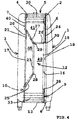
- the suitcase side 5 may include a side-wall 12, split into sectors articulated 41, 42, 65, defined by a first side 18 articulated along a stretch of articulation 16 with respect to the corresponding side 19 of the edge 2 of the front shell 1 and a second side 20 articulated along a stretch of articulation 17 with respect to side 21 of the edge 4 of the rear shell 3.
- the side-wall 12 also has a line of intermediate articulation line 23 parallel to the first and second sides 18, 20.
- the side-wall 12 being articulated along the intermediate articulation line 23 folds parallel to the edges of the articulation with the shells 1, 3 and allows the two shells 1, 3 to overlap with precision along the respective edges while maintaining the physical continuity with side 5 by means of the articulation lines 16, 17 so that they can be stable therefore not detachable.
- first linear joining element 9 is extended to at least a portion 24 of the first edge 18 of the side-wall 12 as to allow the opening and closing of shell 1 relative to side-wall 12, and the second linear joining element 10 is extended between the first and second ends 28, 29 of the articulation line 23 and includes preferably two portions 25, 27 which in turn extend from the ends of the stretch of articulation 17 to the ends of the intermediate line 23.
- the side-wall 12 also comprises of a second intermediate articulation line 26 orthogonal to the stretches of articulation 16, 17 and extended from one end 39 of the stretch of articulation 16 to one end 29 of the first intermediate articulation line 23. Still with reference to Fig. 4 , with the configuration as described, the side-wall 12 of the suitcase is articulated:
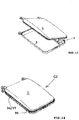
- Figures 8-14 show the succession of the phases from the suitcase in open expanded configuration to the collapsed configuration of minimum volume.
- Fig. 8 9 the two joining elements 9, 10 are completely closed and the shell 1 is articulated to side-wall 12 by means of the stretch of articulation 16.
- the suitcase can be opened ( Fig.9 ) or closed ( Fig.8 ) to access the full internal capacity.
- linear joining elements 9, 10 each comprise two half junction parts 34, 35; 36, 37, of which
- the first joining element 9 is accessible from the outside of the suitcase, while the second joining element 10 is accessible and visible from the inside of the suitcase once the first junction 9 is opened.
- joining elements 9, 10 are both completely open, the side-wall 12 is cut by the opened joining stretches 25 and 27, and side 5 is attached to the shells 1, 3 only by the stretches of articulation 16, 17 of the side-wall 12.
- Side 5 can therefore begin to fold on the angular joints 30, 31, 32, 33, on the line of intermediate articulation line 26 of the side-wall 12 and the intermediate articulation line 11 of the bottom side-wall 13.
- the angular articulation 31 next to the intermediate articulation line 26 and the intermediate articulation line 11 of the side-wall 13 are fixed towards the interior of the suitcase so that sections 41, 42 of the sidewall 12 articulated along the intermediate line 26 are overlapped, the opposite side-wall 15 approaches side-wall 12, and side 5 may collapse against sidewall 12 with a bellows movement.
- angular joints 30-33 are preferably constructed by articulation bands namely provided of more articulation lines, for the purpose of being able, where necessary, for example in folding corner 31, to bend the angle of the side both outward or inward.
- side 5 is collapsed against side-wall 12 that can bend along the intermediate line 23 and allowing the collapsed side 5 to align parallel to shells 1, 3 ( Fig.12-Fig.13 ) inside the suitcase.
- Fig. 15 shows, in greater detail, the method of folding side-wall 12 which is articulated into line 23 and it is free to slide shut due to cuts of the traits of open joining stretches 25, 27.
- the intermediate articulation line 23 of side-wall 12, located at the half width of side-wall 12, in combination with cuts 25, 27, allows the two shells 1, 3 to overlap with precision in the closing collapsed configuration and to match the respective edges 2, 4.
- Fig. 14 shows the closed configuration suitcase, with the collapsed side 5 inwards.
- the linear joining elements 9, 10, are constituted by a zipper or "zip" type.
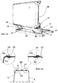
- Fig.16 shows detail of a preferred shape of the suitcase, in which side 5 comprises of an upper side-wall 14 extended without joints between the two angular portions 30, 31 and is provided with external lateral abutment surfaces 51, 52, overlapping to the inner surfaces of abutment corresponding to sides 53, 54 of the front and rear shells 1,3.
- the upper side-wall 14 is therefore capable of bearing the suitcase weight and is provided for the purpose of a handle 55 accessible from the outside for the purpose of carrying.
- side-wall 15 of side 5 opposite to the collapsing side-wall 12, which may itself be provided with a carrying handle 56.
- FIGS 18a, 18b it is shown a possible “trolley" configuration, respectively, in the expanded configuration and in the reduced configuration, in which only two wheels 60 are provided, fixed underneath to the rear body shell 3.
- Figures 17a, 17b show in greater detail the sections of two possible realization forms of angular joint portion 30-33, which can be formed by a succession of slats or cylinders 64 connected for example by a coating of fabric (or co-molded in plastic material) and flexible in both bending directions ( fig.17a ), or by slats 62 put next to each other and connected by lines of reduced thickness 63 with articulation function ( fig.17b ).
- Figures 19a and 19b show the inner section of the suitcase, with the highlighted fold pattern of side 5 between the two shells 1 and 3, in the collapsed configuration, with the angular joints in the form shown in Figures 17a and 17b respectively.
- the invention achieves important advantages.
- the structure described above makes it possible to realize a suitcase that in its expanded configuration has an increased volume, but in its collapsed configuration has a much reduced volume, at the same time being easy and quickly transformed between states with no removable pieces to store separately.
- the invention allows handles to be mounted in a barycentric position, on the upper and lateral sidewalls (for example in the view of Fig. 1 ), thereby facilitating carrying.
- a further advantageous feature consist to the fact that, thanks to the overlap between shell and the side, the zips are not directly stressed, as they only serve to connect the rigid sections and therefore it avoids any misalignment of the rigid parts with a consequent deformation of the whole suitcase during lifting or when the suitcase is lifted by the handle.
- a further advantageous feature is that the articulated corners are composed of a series of rigid elements and articulated between themselves like a chain, in such a way, that when they are inserted in a rigid channel, (connection between shell1, shell 2), they become segments of union for both parts and become more resistant to deformation.
- a further advantageous feature consist in the fact that the inner linear joining element 10 is not accessible from the outside when the suitcase is used in its expanded configuration, and therefore will reduce the chance of tampering.
Landscapes
- Purses, Travelling Bags, Baskets, Or Suitcases (AREA)
- Undergarments, Swaddling Clothes, Handkerchiefs Or Underwear Materials (AREA)
Description
- The invention relates to a suitcase, for example a travel suitcase, of variable volume, that during the use can change from an expanded configuration for maximum volume to contain and transport objects, clothes etc. to a collapsed configuration of minimum volume when the suitcase has to be stored.
- More in detail the suitcase of invention is a rigid or semi-rigid type suitcase with a collapsible structure in which, one, or more of the side-walls are foldable so you can switch from one configuration to another.
- Currently collapsible suitcases are already known.
- An example is represented by the international patent application
WO2013056392 . - In this document a suitcase is described consisting of two shells, one front and one rear, joined together by two parallel zips to a lateral side composed of foldable side-walls, in which the presence of the double zip has the purpose to pair side-walls in different measures.
- In the first example (
fig.5 ), by fully opening both zips, one lateral side can be detached and folded by retracting some of the side-walls, in this specific example two opposite sidewalls are folded inwards. - Therefore, the lateral side reduces its volume and can be placed between the two shells that may in turn be connected again by means of one of the zip, reducing the overall dimensions of the suitcase to the maximum level represented by thickness or height of the lateral side.
- However, this well known suitcase has some drawbacks.
- The first drawback is due to the fact that to pass from one configuration to another it is always necessary to completely disconnect at least one shell in order to subsequently reattach the shells together.
- Further drawback consist in the fact that in the expanded configuration, both front and rear shells are connected by a portion of zip that is subject to efforts and tensions that could potentially damage it, either when both shells are to be opened and closed to fill the suitcase or during the process of lifting and transportation of the suitcase.
- A further drawback is due to the fact that in the reduced configuration, the detachable lateral side must be stored separately.
- A further drawback is due to the fact that the corners of lateral side are substantially rigid and do not allow a complete bellow folding of the lateral side.
- A further drawback of this example of realization is that due to the joints of the lateral sidewalls, is not possible to put a lateral handle in a barycentric position, with subsequent difficulties in handling and transportation of the suitcase.
- In a further example given in the document
WO2013056392 (fig.1 ), the side is not completely detachable, but is fixed with one edge to one of the shells and is equipped with a half-zip along the free edge. In this case, the lateral side is made of a continuous sidewall linked by corner portions collapsible with bellow movement, such that to vary the suitcase configuration it is always necessary to detach a shell, but you can open a single zip, fold the side corners with bellow movement, and fold the side-walls inward before to connect once again the two shells. - The present invention intends to overcome the drawbacks of any already known solutions proposing a suitcase with a collapsible rigid structure, without the need for divisible parts, at the same time having a robust configuration when expanded and easily changed from the expanded configuration to the collapsed one and vice versa.
- These purposes have been achieved realizing a suitcase according to at least one of the attached claims.
- The first advantage consists of the fact that to pass from the expanded to the collapsed configuration it is not necessary to detach the lateral side of the suitcase, but it is possible to maintain the physical continuity of lateral side with the shells, and to overlap the shells in the collapsed configuration even if made by rigid or semi-rigid material.
- A further advantage consists in the simplicity and speed of the actions that the user must perform to convert the suitcase from the expanded configuration to the collapsed and vice versa.
- A further advantage lies in the robustness of the suitcase in its expanded configuration when used as a container and when carried.
- A further advantage consists in the possibility of applying barycentric carrying handles.
- A further advantage consists of providing a double zip, where each zip performs distinct functions for construction of the structure in expanded configuration and in traditional opening and closing of the suitcase.
- A further advantage is due to the fact that the zip providing the structural assembly is not accessible from the outside in the ordinary use of the suitcase thus increasing security against possible tampering.
- A further advantage is due to the fact that the zips are not subject to structural stress during lifting and / or opening and closing of the suitcase.
- These and others advantages will be best understood by someone skilled in this specific field, from the following descriptions and attached drawings, given as nonlimiting examples, in which:
-
Fig.1 shows a front elevation of the suitcase according to the invention; -
Fig. 2 shows a rear view of the suitcase offig.1 ; -
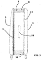
Fig. 3 shows a first side view of the suitcase offig.1 ; -
Fig. 4 shows a second side view of the suitcase offig.1 ; -
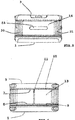
Fig. 5 shows a top view of the suitcase offig.1 ; -
Fig. 6 shows a bottom view of the suitcase offig.1 ; -
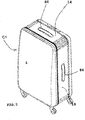
Fig. 7 shows an isometric view of the suitcase offig.1 ; -
Fig. 8-14 shows successive views of the suitcase offig.1 in transition from expanded to collapsed configuration; -
Fig.15 shows a detailed isometric view offig.1 of the suitcase in an intermediate stage of collapse; -
Fig. 16 shows a detail cross section in elevation of the suitcase. -
Fig. 17a and 17b show a schematic detail of the articulated corners portions of the lateral sides of the suitcase. -
Fig. 18a and 18b show an embodiment of the suitcase with only two wheels, in the expanded and collapsed configuration respectively. -
Fig. 19a, 19b shows a schematic view of the inside of the suitcase when collapsed. -
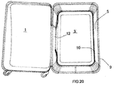
Fig. 20 shows the suitcase in the expanded open configuration from above. - Described with reference to the attached drawings is a collapsible suitcase structure according to the invention.
- The suitcase comprises of a
front shell 1 provided with anedge 2, and arear shell 3 provided with anedge 4, whereby theedges fig.14 ). - Preferably, but not in a limiting sense, both
shells - The suitcase also comprises of a
perimeter side 5 which constitutes a frame for spacing the front and rear shells, generally quadrangular shape with plurality ofsidewalls first edge 6 which extends in correspondence of theedge 2 of thefront shell 1, and asecond edge 7, which extends in correspondence of theedge 4 of therear shell 3. - At least one of the side-
walls perimeter side 5 is provided with at least oneintermediate folding line 11 orthogonal to theedges side 5, and furthermore, are connected by folding articulated angularjoint portions intermediate fold line 11 is provided on the side-wall 13 the lower bottom of theside 5 and it is arranged to allow a folding towards the inside of the suitcase. - According to the invention, there is provided a first reversible linear joining
element 9 arranged to connect at least to a portion of thefirst edge 6 ofside 5 to, at least, a portion of theedge 2 offront shell 1, and a second reversible linear joiningelement 10 arranged to connect, to at least, a portion of thesecond edge 7 ofside 5 to at least a portion of theedge 4 of therear shell 3. - Preferably, the
linear joining elements - As it is best seen in
Fig. 4 , in the illustrated shape of realization, thesuitcase side 5 may include a side-wall 12, split into sectors articulated 41, 42, 65, defined by afirst side 18 articulated along a stretch ofarticulation 16 with respect to thecorresponding side 19 of theedge 2 of thefront shell 1 and asecond side 20 articulated along a stretch ofarticulation 17 with respect toside 21 of theedge 4 of therear shell 3. According to the invention, the side-wall 12 also has a line ofintermediate articulation line 23 parallel to the first andsecond sides - Thanks to this solution, when the suitcase is transformed to the collapsed configuration, the side-
wall 12, being articulated along theintermediate articulation line 23, folds parallel to the edges of the articulation with theshells shells side 5 by means of thearticulation lines - Preferably the first linear joining
element 9 is extended to at least aportion 24 of thefirst edge 18 of the side-wall 12 as to allow the opening and closing ofshell 1 relative to side-wall 12, and the second linear joiningelement 10 is extended between the first andsecond ends articulation line 23 and includes preferably twoportions articulation 17 to the ends of theintermediate line 23. - The side-
wall 12 also comprises of a secondintermediate articulation line 26 orthogonal to the stretches ofarticulation end 39 of the stretch ofarticulation 16 to oneend 29 of the firstintermediate articulation line 23. Still with reference toFig. 4 , with the configuration as described, the side-wall 12 of the suitcase is articulated: - at 16 and 17 with respect to the
shells - at 30 and 33 with respect of the upper side-wall14 and lower side-
wall 13 ofside 5, - With the
intermediate line 23 parallel to thearticulation lines - With the
intermediate line 26 comprised and orthogonal between thelateral articulation line 16 and theintermediate line 23; -
Figures 8-14 show the succession of the phases from the suitcase in open expanded configuration to the collapsed configuration of minimum volume. - In
Fig. 8 ,9 the two joiningelements shell 1 is articulated to side-wall 12 by means of the stretch ofarticulation 16. By opening andclosing joining element 9, the suitcase can be opened (Fig.9 ) or closed (Fig.8 ) to access the full internal capacity. - In greater detail, the above mentioned linear joining
elements half junction parts - The
half part 34 is fixed insideedge 2 ofshell 1, - The
half part 35 is fixed to the outside of theedge 18 of theside 5 - The
half part 36 is fixed to the outside of theedge 20 of theside 5 - The
half part 37 is fixed inside theedge 4 of theshell 3. - Preferably, according to the invention, the first joining
element 9 is accessible from the outside of the suitcase, while the second joiningelement 10 is accessible and visible from the inside of the suitcase once thefirst junction 9 is opened. - In the figures, the visible parts of joining
elements - In
fig.10 , joiningelements wall 12 is cut by the opened joiningstretches side 5 is attached to theshells articulation wall 12.Side 5 can therefore begin to fold on theangular joints intermediate articulation line 26 of the side-wall 12 and theintermediate articulation line 11 of the bottom side-wall 13. In more detail, theangular articulation 31 next to theintermediate articulation line 26 and theintermediate articulation line 11 of the side-wall 13 are fixed towards the interior of the suitcase so thatsections sidewall 12 articulated along theintermediate line 26 are overlapped, the opposite side-wall 15 approaches side-wall 12, andside 5 may collapse againstsidewall 12 with a bellows movement. - It is noted that the angular joints 30-33 are preferably constructed by articulation bands namely provided of more articulation lines, for the purpose of being able, where necessary, for example in folding
corner 31, to bend the angle of the side both outward or inward. - In
fig.11 ,side 5 is collapsed against side-wall 12 that can bend along theintermediate line 23 and allowing thecollapsed side 5 to align parallel toshells 1, 3 (Fig.12-Fig.13 ) inside the suitcase. -
Fig. 15 shows, in greater detail, the method of folding side-wall 12 which is articulated intoline 23 and it is free to slide shut due to cuts of the traits of open joiningstretches - Advantageously, it is noted that, the
intermediate articulation line 23 of side-wall 12, located at the half width of side-wall 12, in combination withcuts shells respective edges -
Fig. 14 shows the closed configuration suitcase, with thecollapsed side 5 inwards. - In a preferred example of embodiment, the linear joining
elements -
Fig.16 shows detail of a preferred shape of the suitcase, in whichside 5 comprises of an upper side-wall 14 extended without joints between the twoangular portions sides rear shells - In this form, the upper side-
wall 14 is therefore capable of bearing the suitcase weight and is provided for the purpose of ahandle 55 accessible from the outside for the purpose of carrying. - A similar consideration applies to side-
wall 15 ofside 5, opposite to the collapsing side-wall 12, which may itself be provided with a carryinghandle 56. - It is specified that the highlighted section in
Figure 16 extends around the entire perimeter ofside 5 in correspondence ofedges rear shells wheels 60 fixed to the body of theshells removable handle 61 from therear shell 3, like a "Trolley" which is already know and therefore not further described. - In
figures 18a, 18b it is shown a possible "trolley" configuration, respectively, in the expanded configuration and in the reduced configuration, in which only twowheels 60 are provided, fixed underneath to therear body shell 3. In this case it will be possible to advantageously reduce the overall depth of thefront shell 1 which may have a substantially flat form with additional benefit in reducing the total volume of the collapsed suitcase
Figures 17a, 17b show in greater detail the sections of two possible realization forms of angular joint portion 30-33, which can be formed by a succession of slats orcylinders 64 connected for example by a coating of fabric (or co-molded in plastic material) and flexible in both bending directions (fig.17a ), or byslats 62 put next to each other and connected by lines of reduced thickness 63 with articulation function (fig.17b ). -
Figures 19a and 19b show the inner section of the suitcase, with the highlighted fold pattern ofside 5 between the twoshells Figures 17a and 17b respectively. - The invention achieves important advantages.
- The structure described above makes it possible to realize a suitcase that in its expanded configuration has an increased volume, but in its collapsed configuration has a much reduced volume, at the same time being easy and quickly transformed between states with no removable pieces to store separately.
- Furthermore, the invention allows handles to be mounted in a barycentric position, on the upper and lateral sidewalls (for example in the view of
Fig. 1 ), thereby facilitating carrying. - A further advantageous feature, consist to the fact that, thanks to the overlap between shell and the side, the zips are not directly stressed, as they only serve to connect the rigid sections and therefore it avoids any misalignment of the rigid parts with a consequent deformation of the whole suitcase during lifting or when the suitcase is lifted by the handle.
- A further advantageous feature is that the articulated corners are composed of a series of rigid elements and articulated between themselves like a chain, in such a way, that when they are inserted in a rigid channel, (connection between shell1, shell 2), they become segments of union for both parts and become more resistant to deformation.
- A further advantageous feature consist in the fact that the inner linear joining
element 10 is not accessible from the outside when the suitcase is used in its expanded configuration, and therefore will reduce the chance of tampering. - The invention has been described with reference to a preferred form of embodiment, however it is understood that equivalent modifications may be made as long as they do not depart from the scope of invention as defined in appended claims.
Claims (10)
- A suitcase with collapsible structure, capable of assuming an expanded configuration of normal use (C1) and a collapsed configuration (C2), comprising:a front shell (1) provided with a perimetral edge (2);a rear shell (3) provided with a perimetral edge (4) that can be associated to the edge (2) of the front shell (1);a perimetral side (5) for distancing said front and rear shells, comprising a plurality of distancing walls (12, 13, 14, 15) defined between a first edge (6) that in the configuration of use extends at the edge (2) of the front shell (1) and a second edge (7) that extends at the edge (4) of the rear shell (3), said walls being connected by foldable articulated angular portions (30, 31, 32, 33);a first reversible linear joining element (9) for connecting at least one stretch of the first edge (6) of the side (5) to at least one stretch of the edge (2) of the front shell (1); anda second reversible linear joining element (10) for connecting at least one stretch of the second edge (7) of the side (5) to at least one stretch of the edge (4) of the rear shell (3);
wherein at least one wall (12, 13, 14, 15) of the side (5) is provided with at least one intermediate folding line (11) orthogonal to the edges (6, 7) of the side (5),wherein said side (5) comprises a wall (12) defined by a first side (18) that can be articulated along a stretch (16) of articulation with respect to a side (19) of the edge (2) of the front shell (1) and a second side (20) that can be articulated along a stretch (17) of articulation with respect to a side (21) of the edge (4) of the rear shell (3); andsaid wall (12) comprises a first intermediate articulation line (23) comprised between and parallel to said articulation stretches (16, 17) of the wall (12). - The suitcase according to Claim 1, characterized in that:said first linear joining element (9) extends for at least one openable joining stretch (24) of the first edge (18) of the wall (12), which runs from one end to the other (38, 39) of the articulation stretch (16) to enable reversible opening and closing of the shell (1) with respect to the side (5) of the suitcase;said second linear joining element (10) extends for at least one openable joining stretch (40) that runs from one end (28) to the other end (29) of said first intermediate articulation line (23); andsaid wall (12) comprises a second intermediate articulation line (26) orthogonal to said articulation stretches (16, 17) of the wall (12), which extends from the side (18) to one end (29) of the first intermediate articulation line (23).
- The suitcase according to Claim 2, wherein the second intermediate articulation line (26) orthogonal to said articulation stretches (16, 17) of the wall (12) extends from one end (39) of the articulation stretch (16) to one end (29) of the first intermediate articulation line (23).
- The suitcase according to any one of the preceding claims, wherein said first linear joining element (9) is accessible for being operated from outside the suitcase, and said second linear joining element (10) is accessible for being operated only inside the suitcase.
- The suitcase according to any one of the preceding claims, wherein said joining stretch (40) of the second linear joining 3 element (10) extends for at least one joining stretch (25, 27) that runs from the second edge (20) of the wall (12) to one end (28, 29) of said first intermediate articulation line (23).
- The suitcase according to Claim 5, comprising two joining stretches (25, 27) that run from the ends of the articulation stretch (17) to the respective ends (28, 29) of the first intermediate articulation line (23).
- The suitcase according to any one of the preceding claims, wherein said at least one intermediate folding line (11) is provided in a bottom wall (13) of the side (5).
- The suitcase according to any one of the preceding claims, wherein said side comprises a top wall (14) extending without articulations between two angular portions (30, 31) and provided with external lateral contrast surfaces (32, 33) that can be superimposed on internal contrast surfaces of corresponding sides (34, 35) of the front and rear shells (1, 3), said top wall (14) being provided with a handle (55) accessible from outside for carrying the suitcase.
- The suitcase according to any one of the preceding claims, wherein at least one of said linear joining elements (9, 10) is constituted by a zip fastener.
- The suitcase according to any one of the preceding claims, wherein at least one of said shells (1, 3) is a shell having a concave shape made of a rigid or semi-rigid material, for example polypropylene, polycarbonate, EVA.
Applications Claiming Priority (2)
| Application Number | Priority Date | Filing Date | Title |
|---|---|---|---|
| ITUB2015A005228A ITUB20155228A1 (en) | 2015-10-16 | 2015-10-16 | SUITCASE WITH A COLLASSABLE STRUCTURE |
| PCT/IT2016/000241 WO2017064739A1 (en) | 2015-10-16 | 2016-10-17 | Suitcase with collapsible structure |
Publications (2)
| Publication Number | Publication Date |
|---|---|
| EP3361901A1 EP3361901A1 (en) | 2018-08-22 |
| EP3361901B1 true EP3361901B1 (en) | 2020-03-25 |
Family
ID=55315638
Family Applications (1)
| Application Number | Title | Priority Date | Filing Date |
|---|---|---|---|
| EP16812878.3A Active EP3361901B1 (en) | 2015-10-16 | 2016-10-17 | Suitcase with collapsible structure |
Country Status (3)
| Country | Link |
|---|---|
| EP (1) | EP3361901B1 (en) |
| IT (1) | ITUB20155228A1 (en) |
| WO (1) | WO2017064739A1 (en) |
Families Citing this family (6)
| Publication number | Priority date | Publication date | Assignee | Title |
|---|---|---|---|---|
| IL261016A (en) | 2018-08-06 | 2019-01-31 | Keter Holdings Ltd | Suitcase |
| US12127654B2 (en) | 2019-04-12 | 2024-10-29 | Marwin Gmbh | Foldable wheeled suitcase and steering roller |
| DE202019001691U1 (en) * | 2019-04-12 | 2020-07-14 | Marwin Gmbh | Foldable suitcase with zip and side wheels |
| LU500217B1 (en) | 2021-05-28 | 2022-11-28 | Hey Circle Gmbh I G | Foldable transport container |
| LU500218B1 (en) * | 2021-05-28 | 2022-11-28 | Hey Circle Gmbh I G | Foldable transport container |
| CN216453766U (en) * | 2021-12-17 | 2022-05-10 | 上海海琛国际贸易有限公司 | A foldable suitcase |
Family Cites Families (1)
| Publication number | Priority date | Publication date | Assignee | Title |
|---|---|---|---|---|
| WO2013056392A1 (en) * | 2011-10-18 | 2013-04-25 | 伯勒仕有限公司 | Suitcase structure |
-
2015
- 2015-10-16 IT ITUB2015A005228A patent/ITUB20155228A1/en unknown
-
2016
- 2016-10-17 EP EP16812878.3A patent/EP3361901B1/en active Active
- 2016-10-17 WO PCT/IT2016/000241 patent/WO2017064739A1/en not_active Ceased
Non-Patent Citations (1)
| Title |
|---|
| None * |
Also Published As
| Publication number | Publication date |
|---|---|
| ITUB20155228A1 (en) | 2017-04-16 |
| EP3361901A1 (en) | 2018-08-22 |
| WO2017064739A1 (en) | 2017-04-20 |
Similar Documents
| Publication | Publication Date | Title |
|---|---|---|
| EP3361901A1 (en) | Suitcase with collapsible structure | |
| US20240164496A1 (en) | Suitcase | |
| US10226108B2 (en) | Collapsible containers | |
| JP2017095177A (en) | Collapsible type box | |
| US3949933A (en) | Collapsible container | |
| CN206760992U (en) | luggage case | |
| MX2014012621A (en) | Improved tote bad. | |
| US9265317B2 (en) | Support structure for luggage | |
| US20140151174A1 (en) | Suitcase having an improved structure | |
| US20170042301A1 (en) | Luggage with a collapsible structure | |
| US11097887B2 (en) | Insulated container with folding closure | |
| US11267613B2 (en) | Origami-based collapsible and watertight cases | |
| EP3590381B1 (en) | A luggage article comprising bottom structure | |
| KR101245161B1 (en) | Foldable suit case | |
| JP3130529U (en) | Shopping bag | |
| US9963261B2 (en) | Reusable foldable food storage and serving container | |
| KR20230001990U (en) | Folding wagon with 2-stage storage structure | |
| ITTO20140107U1 (en) | FOLDABLE BAG | |
| RU232353U1 (en) | Transformer suitcase | |
| KR200477609Y1 (en) | Pocket cart for multi purpose and portable type | |
| US11083261B2 (en) | Collapsible luggage | |
| HK40050295A (en) | Luggage article split along front and rear major faces | |
| HK40050295B (en) | Luggage article split along front and rear major faces | |
| HK1256175B (en) | Luggage article with an external compartment | |
| ITMI20090259U1 (en) | FOLDABLE AND TRANSFORMABLE BAG |
Legal Events
| Date | Code | Title | Description |
|---|---|---|---|
| STAA | Information on the status of an ep patent application or granted ep patent |
Free format text: STATUS: UNKNOWN |
|
| STAA | Information on the status of an ep patent application or granted ep patent |
Free format text: STATUS: THE INTERNATIONAL PUBLICATION HAS BEEN MADE |
|
| PUAI | Public reference made under article 153(3) epc to a published international application that has entered the european phase |
Free format text: ORIGINAL CODE: 0009012 |
|
| STAA | Information on the status of an ep patent application or granted ep patent |
Free format text: STATUS: REQUEST FOR EXAMINATION WAS MADE |
|
| 17P | Request for examination filed |
Effective date: 20180607 |
|
| AK | Designated contracting states |
Kind code of ref document: A1 Designated state(s): AL AT BE BG CH CY CZ DE DK EE ES FI FR GB GR HR HU IE IS IT LI LT LU LV MC MK MT NL NO PL PT RO RS SE SI SK SM TR |
|
| AX | Request for extension of the european patent |
Extension state: BA ME |
|
| DAV | Request for validation of the european patent (deleted) | ||
| DAX | Request for extension of the european patent (deleted) | ||
| GRAP | Despatch of communication of intention to grant a patent |
Free format text: ORIGINAL CODE: EPIDOSNIGR1 |
|
| STAA | Information on the status of an ep patent application or granted ep patent |
Free format text: STATUS: GRANT OF PATENT IS INTENDED |
|
| INTG | Intention to grant announced |
Effective date: 20190524 |
|
| GRAS | Grant fee paid |
Free format text: ORIGINAL CODE: EPIDOSNIGR3 |
|
| GRAA | (expected) grant |
Free format text: ORIGINAL CODE: 0009210 |
|
| STAA | Information on the status of an ep patent application or granted ep patent |
Free format text: STATUS: THE PATENT HAS BEEN GRANTED |
|
| AK | Designated contracting states |
Kind code of ref document: B1 Designated state(s): AL AT BE BG CH CY CZ DE DK EE ES FI FR GB GR HR HU IE IS IT LI LT LU LV MC MK MT NL NO PL PT RO RS SE SI SK SM TR |
|
| REG | Reference to a national code |
Ref country code: GB Ref legal event code: FG4D |
|
| REG | Reference to a national code |
Ref country code: CH Ref legal event code: EP |
|
| REG | Reference to a national code |
Ref country code: DE Ref legal event code: R096 Ref document number: 602016025245 Country of ref document: DE |
|
| REG | Reference to a national code |
Ref country code: AT Ref legal event code: REF Ref document number: 1205752 Country of ref document: AT Kind code of ref document: T Effective date: 20191215 |
|
| REG | Reference to a national code |
Ref country code: IE Ref legal event code: FG4D |
|
| PUAC | Information related to the publication of a b1 document modified or deleted |
Free format text: ORIGINAL CODE: 0009299EPPU |
|
| STAA | Information on the status of an ep patent application or granted ep patent |
Free format text: STATUS: GRANT OF PATENT IS INTENDED |
|
| REG | Reference to a national code |
Ref country code: CH Ref legal event code: PK Free format text: DIE ERTEILUNG WURDE VOM EPA WIDERRUFEN. |
|
| DB1 | Publication of patent cancelled |
Effective date: 20200117 |
|
| GRAA | (expected) grant |
Free format text: ORIGINAL CODE: 0009210 |
|
| STAA | Information on the status of an ep patent application or granted ep patent |
Free format text: STATUS: THE PATENT HAS BEEN GRANTED |
|
| REG | Reference to a national code |
Ref country code: LU Ref legal event code: HK Effective date: 20200212 |
|
| RAP1 | Party data changed (applicant data changed or rights of an application transferred) |
Owner name: CHIARA CARAMELLI DESIGN LAB |
|
| REG | Reference to a national code |
Ref country code: DE Ref legal event code: R081 Ref document number: 602016025245 Country of ref document: DE Owner name: CHIARA CARAMELLI DESIGN LAB, IT Free format text: FORMER OWNER: CARAMELLI, CHIARA, PONTASSIEVE, IT |
|
| REG | Reference to a national code |
Ref country code: DE Ref legal event code: R107 Ref document number: 602016025245 Country of ref document: DE |
|
| REG | Reference to a national code |
Ref country code: AT Ref legal event code: REZ Ref document number: 1205752 Country of ref document: AT Kind code of ref document: T Effective date: 20191127 |
|
| AK | Designated contracting states |
Kind code of ref document: B1 Designated state(s): AL AT BE BG CH CY CZ DE DK EE ES FI FR GB GR HR HU IE IS IT LI LT LU LV MC MK MT NL NO PL PT RO RS SE SI SK SM TR |
|
| REG | Reference to a national code |
Ref country code: GB Ref legal event code: FG4D |
|
| REG | Reference to a national code |
Ref country code: AT Ref legal event code: REF Ref document number: 1205752 Country of ref document: AT Kind code of ref document: T Effective date: 20200415 |
|
| REG | Reference to a national code |
Ref country code: DE Ref legal event code: R096 Ref document number: 602016025245 Country of ref document: DE |
|
| PG25 | Lapsed in a contracting state [announced via postgrant information from national office to epo] |
Ref country code: RS Free format text: LAPSE BECAUSE OF FAILURE TO SUBMIT A TRANSLATION OF THE DESCRIPTION OR TO PAY THE FEE WITHIN THE PRESCRIBED TIME-LIMIT Effective date: 20200325 Ref country code: IS Free format text: LAPSE BECAUSE OF FAILURE TO SUBMIT A TRANSLATION OF THE DESCRIPTION OR TO PAY THE FEE WITHIN THE PRESCRIBED TIME-LIMIT Effective date: 20200327 |
|
| PG25 | Lapsed in a contracting state [announced via postgrant information from national office to epo] |
Ref country code: NO Free format text: LAPSE BECAUSE OF FAILURE TO SUBMIT A TRANSLATION OF THE DESCRIPTION OR TO PAY THE FEE WITHIN THE PRESCRIBED TIME-LIMIT Effective date: 20200625 Ref country code: FI Free format text: LAPSE BECAUSE OF FAILURE TO SUBMIT A TRANSLATION OF THE DESCRIPTION OR TO PAY THE FEE WITHIN THE PRESCRIBED TIME-LIMIT Effective date: 20200325 |
|
| PG25 | Lapsed in a contracting state [announced via postgrant information from national office to epo] |
Ref country code: HR Free format text: LAPSE BECAUSE OF FAILURE TO SUBMIT A TRANSLATION OF THE DESCRIPTION OR TO PAY THE FEE WITHIN THE PRESCRIBED TIME-LIMIT Effective date: 20200325 Ref country code: BG Free format text: LAPSE BECAUSE OF FAILURE TO SUBMIT A TRANSLATION OF THE DESCRIPTION OR TO PAY THE FEE WITHIN THE PRESCRIBED TIME-LIMIT Effective date: 20200625 Ref country code: LV Free format text: LAPSE BECAUSE OF FAILURE TO SUBMIT A TRANSLATION OF THE DESCRIPTION OR TO PAY THE FEE WITHIN THE PRESCRIBED TIME-LIMIT Effective date: 20200325 |
|
| REG | Reference to a national code |
Ref country code: NL Ref legal event code: MP Effective date: 20200325 |
|
| REG | Reference to a national code |
Ref country code: LT Ref legal event code: MG4D |
|
| PG25 | Lapsed in a contracting state [announced via postgrant information from national office to epo] |
Ref country code: NL Free format text: LAPSE BECAUSE OF FAILURE TO SUBMIT A TRANSLATION OF THE DESCRIPTION OR TO PAY THE FEE WITHIN THE PRESCRIBED TIME-LIMIT Effective date: 20200325 |
|
| PG25 | Lapsed in a contracting state [announced via postgrant information from national office to epo] |
Ref country code: CZ Free format text: LAPSE BECAUSE OF FAILURE TO SUBMIT A TRANSLATION OF THE DESCRIPTION OR TO PAY THE FEE WITHIN THE PRESCRIBED TIME-LIMIT Effective date: 20200325 Ref country code: RO Free format text: LAPSE BECAUSE OF FAILURE TO SUBMIT A TRANSLATION OF THE DESCRIPTION OR TO PAY THE FEE WITHIN THE PRESCRIBED TIME-LIMIT Effective date: 20200325 Ref country code: PT Free format text: LAPSE BECAUSE OF FAILURE TO SUBMIT A TRANSLATION OF THE DESCRIPTION OR TO PAY THE FEE WITHIN THE PRESCRIBED TIME-LIMIT Effective date: 20200810 Ref country code: SK Free format text: LAPSE BECAUSE OF FAILURE TO SUBMIT A TRANSLATION OF THE DESCRIPTION OR TO PAY THE FEE WITHIN THE PRESCRIBED TIME-LIMIT Effective date: 20200325 Ref country code: LT Free format text: LAPSE BECAUSE OF FAILURE TO SUBMIT A TRANSLATION OF THE DESCRIPTION OR TO PAY THE FEE WITHIN THE PRESCRIBED TIME-LIMIT Effective date: 20200325 Ref country code: SM Free format text: LAPSE BECAUSE OF FAILURE TO SUBMIT A TRANSLATION OF THE DESCRIPTION OR TO PAY THE FEE WITHIN THE PRESCRIBED TIME-LIMIT Effective date: 20200325 Ref country code: EE Free format text: LAPSE BECAUSE OF FAILURE TO SUBMIT A TRANSLATION OF THE DESCRIPTION OR TO PAY THE FEE WITHIN THE PRESCRIBED TIME-LIMIT Effective date: 20200325 |
|
| REG | Reference to a national code |
Ref country code: AT Ref legal event code: MK05 Ref document number: 1205752 Country of ref document: AT Kind code of ref document: T Effective date: 20200325 |
|
| REG | Reference to a national code |
Ref country code: DE Ref legal event code: R097 Ref document number: 602016025245 Country of ref document: DE |
|
| PG25 | Lapsed in a contracting state [announced via postgrant information from national office to epo] |
Ref country code: AT Free format text: LAPSE BECAUSE OF FAILURE TO SUBMIT A TRANSLATION OF THE DESCRIPTION OR TO PAY THE FEE WITHIN THE PRESCRIBED TIME-LIMIT Effective date: 20200325 Ref country code: DK Free format text: LAPSE BECAUSE OF FAILURE TO SUBMIT A TRANSLATION OF THE DESCRIPTION OR TO PAY THE FEE WITHIN THE PRESCRIBED TIME-LIMIT Effective date: 20200325 Ref country code: ES Free format text: LAPSE BECAUSE OF FAILURE TO SUBMIT A TRANSLATION OF THE DESCRIPTION OR TO PAY THE FEE WITHIN THE PRESCRIBED TIME-LIMIT Effective date: 20200325 |
|
| PLBE | No opposition filed within time limit |
Free format text: ORIGINAL CODE: 0009261 |
|
| STAA | Information on the status of an ep patent application or granted ep patent |
Free format text: STATUS: NO OPPOSITION FILED WITHIN TIME LIMIT |
|
| 26N | No opposition filed |
Effective date: 20210112 |
|
| PG25 | Lapsed in a contracting state [announced via postgrant information from national office to epo] |
Ref country code: SI Free format text: LAPSE BECAUSE OF FAILURE TO SUBMIT A TRANSLATION OF THE DESCRIPTION OR TO PAY THE FEE WITHIN THE PRESCRIBED TIME-LIMIT Effective date: 20200325 |
|
| PG25 | Lapsed in a contracting state [announced via postgrant information from national office to epo] |
Ref country code: MC Free format text: LAPSE BECAUSE OF FAILURE TO SUBMIT A TRANSLATION OF THE DESCRIPTION OR TO PAY THE FEE WITHIN THE PRESCRIBED TIME-LIMIT Effective date: 20200325 Ref country code: LU Free format text: LAPSE BECAUSE OF NON-PAYMENT OF DUE FEES Effective date: 20201017 |
|
| PG25 | Lapsed in a contracting state [announced via postgrant information from national office to epo] |
Ref country code: IE Free format text: LAPSE BECAUSE OF NON-PAYMENT OF DUE FEES Effective date: 20201017 |
|
| PG25 | Lapsed in a contracting state [announced via postgrant information from national office to epo] |
Ref country code: TR Free format text: LAPSE BECAUSE OF FAILURE TO SUBMIT A TRANSLATION OF THE DESCRIPTION OR TO PAY THE FEE WITHIN THE PRESCRIBED TIME-LIMIT Effective date: 20200325 Ref country code: MT Free format text: LAPSE BECAUSE OF FAILURE TO SUBMIT A TRANSLATION OF THE DESCRIPTION OR TO PAY THE FEE WITHIN THE PRESCRIBED TIME-LIMIT Effective date: 20200325 Ref country code: CY Free format text: LAPSE BECAUSE OF FAILURE TO SUBMIT A TRANSLATION OF THE DESCRIPTION OR TO PAY THE FEE WITHIN THE PRESCRIBED TIME-LIMIT Effective date: 20200325 |
|
| PG25 | Lapsed in a contracting state [announced via postgrant information from national office to epo] |
Ref country code: SE Free format text: LAPSE BECAUSE OF FAILURE TO SUBMIT A TRANSLATION OF THE DESCRIPTION OR TO PAY THE FEE WITHIN THE PRESCRIBED TIME-LIMIT Effective date: 20200325 Ref country code: MK Free format text: LAPSE BECAUSE OF FAILURE TO SUBMIT A TRANSLATION OF THE DESCRIPTION OR TO PAY THE FEE WITHIN THE PRESCRIBED TIME-LIMIT Effective date: 20200325 Ref country code: AL Free format text: LAPSE BECAUSE OF FAILURE TO SUBMIT A TRANSLATION OF THE DESCRIPTION OR TO PAY THE FEE WITHIN THE PRESCRIBED TIME-LIMIT Effective date: 20200325 |
|
| REG | Reference to a national code |
Ref country code: BE Ref legal event code: MM Effective date: 20221031 |
|
| REG | Reference to a national code |
Ref country code: BE Ref legal event code: NE Effective date: 20230629 |
|
| PG25 | Lapsed in a contracting state [announced via postgrant information from national office to epo] |
Ref country code: GR Free format text: LAPSE BECAUSE OF FAILURE TO SUBMIT A TRANSLATION OF THE DESCRIPTION OR TO PAY THE FEE WITHIN THE PRESCRIBED TIME-LIMIT Effective date: 20200325 |
|
| PG25 | Lapsed in a contracting state [announced via postgrant information from national office to epo] |
Ref country code: PL Free format text: LAPSE BECAUSE OF FAILURE TO SUBMIT A TRANSLATION OF THE DESCRIPTION OR TO PAY THE FEE WITHIN THE PRESCRIBED TIME-LIMIT Effective date: 20200325 |
|
| PG25 | Lapsed in a contracting state [announced via postgrant information from national office to epo] |
Ref country code: BE Free format text: LAPSE BECAUSE OF NON-PAYMENT OF DUE FEES Effective date: 20221031 |
|
| REG | Reference to a national code |
Ref country code: BE Ref legal event code: NF Effective date: 20231106 |
|
| PG25 | Lapsed in a contracting state [announced via postgrant information from national office to epo] |
Ref country code: BE Free format text: LAPSE BECAUSE OF NON-PAYMENT OF DUE FEES Effective date: 20221031 |
|
| PGRI | Patent reinstated in contracting state [announced from national office to epo] |
Ref country code: BE Effective date: 20231106 |
|
| PGFP | Annual fee paid to national office [announced via postgrant information from national office to epo] |
Ref country code: IT Payment date: 20250905 Year of fee payment: 10 |
|
| PGFP | Annual fee paid to national office [announced via postgrant information from national office to epo] |
Ref country code: BE Payment date: 20250909 Year of fee payment: 10 Ref country code: GB Payment date: 20250905 Year of fee payment: 10 |
|
| PGFP | Annual fee paid to national office [announced via postgrant information from national office to epo] |
Ref country code: FR Payment date: 20250905 Year of fee payment: 10 |
|
| PGFP | Annual fee paid to national office [announced via postgrant information from national office to epo] |
Ref country code: DE Payment date: 20250909 Year of fee payment: 10 |
|
| REG | Reference to a national code |
Ref country code: CH Ref legal event code: U11 Free format text: ST27 STATUS EVENT CODE: U-0-0-U10-U11 (AS PROVIDED BY THE NATIONAL OFFICE) Effective date: 20260123 |
|
| PGFP | Annual fee paid to national office [announced via postgrant information from national office to epo] |
Ref country code: CH Payment date: 20260123 Year of fee payment: 10 |